datasheet and technical manual for the nap-79a catalytic gas
TRANSCRIPT

NAP-79A Handling Manual, March 2013
Page 1 of 13
Nemoto Sensor Engineering Company Ltd
Nemoto (Europe) B.V. Burgemeester Haspelslaan 53
1181NB Amstelveen The Netherlands
Tel +31 20 670 3858
Fax +31 20 670 2709 www.nemoto.eu
Datasheet and Technical Manual for the
NAP-79A Catalytic gas sensor for the detection of incomplete combustion in boiler flues
Nemoto has a policy of continuous development and improvement of its products. As such the specification for the device outlined in this document may be changed without notice.
SUNSTAR传感与控制 http://www.sensor-ic.com/ TEL:0755-83376549 FAX:0755-83376182 E-MAIL:[email protected]
SUNSTAR自动化 http://www.sensor-ic.com/ TEL: 0755-83376489 FAX:0755-83376182 E-MAIL:[email protected]

NAP-79A Handling Manual, March 2013
Page 2 of 13
Contents Introduction and General Description……………………………………….. 3 Principles of Operation………………………………………………………………….….. 3
General Specifications…………………………………………………….……. 5
Outline Drawing and Dimensions………………………………..…………… 6 Schematic and Circuit Layout………………..…………………..…………… 7 Performance Measurements……………………………………………….…… 8
Tolerance to Environmental Extremes…………………………………………..…….. 8
Tolerance to Temperature Transients (Heat Shock)……………………………..…. 8
Tolerance to Vibration……………………………………………………………….…... 8
Zero drift with power supply variation………………………………………...….…... 9
Initial Start-up time and optional Heat Cleaning Cycle……….……………………. 10
Long Term Stability, and periodic zero correction………………………………….. 11
Notes for Designers……………………………………………………………… 12
Note that the performance measurements expressed in this document should be considered as typical characteristics for guidance only, and not as specifications which are guaranteed, apart from those in the sections ”General Specifications” and “Dimensions” (Pages 5 and 6). It is the instrument designer’s responsibility to ensure that the sensor is suitable for any given application.
SUNSTAR传感与控制 http://www.sensor-ic.com/ TEL:0755-83376549 FAX:0755-83376182 E-MAIL:[email protected]
SUNSTAR自动化 http://www.sensor-ic.com/ TEL: 0755-83376489 FAX:0755-83376182 E-MAIL:[email protected]

NAP-79A Handling Manual, March 2013
Page 3 of 13
Introduction and General Description The NAP-79A Gas Sensor from Nemoto is designed to continuously monitor the flue gases generated by gas or oil fired domestic hot water and central heating boilers in order to ensure the safety of the device and also to limit the environmental impact of the boiler under fault conditions. The sensor will detect the presence of high levels of carbon monoxide and/or hydrogen in the flue gases generated by the boiler. High levels of these gases in the flue during normal operation occur as a result of incomplete combustion, and hence indicate a faulty boiler which could pose a safety hazard within the dwelling in which it is fitted. The signal from the sensor can be used either to trigger an alarm, or to automatically turn the boiler off to ensure the safety and well-being of the people within the building. The NAP-79A is particularly useful as an indicator of a blocked or partially blocked flue, whether in the flues air intake or in its exhaust stage. Recent changes in standards relating to domestic water heating boilers, particularly the European Standard EN 483, have highlighted the necessity of accurately detecting this fault condition, and the NAP-79A sensor accomplishes this with ease, ensuring compliance with this section of the standard. The sensor uses the well proven Catalyzed Pelletized resistor (Pellistor) method, which is well established for the detection of Flammable gases in general ambient safety applications. In the case of the NAP-79A the device is specially modified to give stable and reliable performance when mounted inside a boiler flue working at high temperatures. The NAP-79A sensor is well proven as a reliable real time warning of unsafe combustion conditions within boilers. Principles of Operation:
Catalytic combustion has been the most widely used method of detecting flammable gases in Industry since the invention of the catalysed pelletized resistor (or "Pellistor") over 40 years ago.
A pellistor consists of a very fine coil of platinum wire, embedded within a ceramic pellet. On the surface of the pellet is a layer of a high surface area noble metal, which, when hot, acts as a catalyst to promote exothermic oxidation of flammable gases. In operation, the pellet and so the catalyst layer is heated by passing a current through the underlying coil. In the presence of a flammable gas or vapour, the hot catalyst allows oxidation to occur in a similar chemical reaction to combustion. Just as in combustion, the reaction releases heat, which causes the temperature of the catalyst together with its underlying pellet and coil to rise. This rise in temperature results in a change in the electrical resistance of the coil, and it is this change in electrical resistance which constitutes the signal from the sensor.
SUNSTAR传感与控制 http://www.sensor-ic.com/ TEL:0755-83376549 FAX:0755-83376182 E-MAIL:[email protected]
SUNSTAR自动化 http://www.sensor-ic.com/ TEL: 0755-83376489 FAX:0755-83376182 E-MAIL:[email protected]

NAP-79A Handling Manual, March 2013
Page 4 of 13
Pellistors are always manufactured in pairs, the active catalysed element being supplied with an electrically matched element which contains no catalyst and is treated to ensure no flammable gas will oxidise on its surface. This "compensator" element is used as a reference resistance to which the sensor's signal is compared, to remove the effects of environmental factors other than the presence of a flammable gas.
Pellistor Drive/Measurement Circuit: A simple Wheatstone Bridge to compare the resistance of two hot elements
The advantage of using this technique when detecting flammable gases for safety purposes is that it measures flammability directly.
Nemoto provides matched pair pellistors conveniently mounted in a variety of enclosures for different applications. Some of these options contain the detector and compensator elements in separate enclosures (the NP range for Industrial safety applications). In the case of the NAP-79A, both elements are contained within a special heat resistant enclosure for ease of use and low cost, whilst the external circuit is supplied on-board the device. The circuit is modified slightly from the diagram above to ensure stable and repeatable performance across the very wide range of temperatures required for this application.
Catalytic pellistor type gas sensors have many advantages to semiconductor type gas sensors
Linear output in proportion to gas concentration Greater Stability Higher reproducibility Gas specific - will only respond to flammable gases Unaffected by humidity Stable output for long periods More resistant to shocks and vibrations.
SUNSTAR传感与控制 http://www.sensor-ic.com/ TEL:0755-83376549 FAX:0755-83376182 E-MAIL:[email protected]
SUNSTAR自动化 http://www.sensor-ic.com/ TEL: 0755-83376489 FAX:0755-83376182 E-MAIL:[email protected]
NAP-79A Handling Manual, March 2013
Page 5 of 13
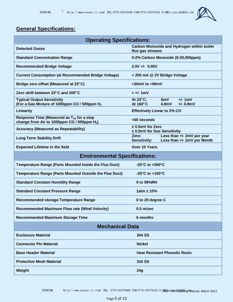
General Specifications:
Operating Specifications: Detected Gases Carbon Monoxide and Hydrogen within boiler
flue gas streams
Standard Concentration Range 0-2% Carbon Monoxide (0-20,000ppm)
Recommended Bridge Voltage 2.0V +/- 0.05V
Current Consumption (at Recommended Bridge Voltage) < 200 mA @ 2V Bridge Voltage
Bridge zero offset (Measured at 23O C) +20mV to +90mV
Zero shift between 23O C and 200O C < +/- 1mV
Typical Output Sensitivity (For a Gas Mixture of 1000ppm CO / 500ppm H2
At 23O C: 6mV +/- 1mV At 160O C 4.8mV +/- 0.8mV
Linearity Effectively Linear to 2% CO
Response Time (Measured as T90 for a step change from Air to 1000ppm CO / 500ppm H2)
<60 seconds
Accuracy (Measured as Repeatability) ± 0.5mV for Zero ± 0.5mV for Gas Sensitivity
Long Term Stability Drift Zero: Sensitivity:
Less than +/- 2mV per year Less than +/- 2mV per Month
Expected Lifetime in the field Over 10 Years.
Environmental Specifications: Temperature Range (Parts Mounted Inside the Flue Duct) -25°C to +260°C
Temperature Range (Parts Mounted Outside the Flue Duct) -25°C to +150°C
Standard Constant Humidity Range 0 to 99%RH
Standard Constant Pressure Range 1atm ± 10%
Recommended storage Temperature Range 0 to 20 degree C
Recommended Maximum Flow rate (Wind Velocity) 0.5 m/sec
Recommended Maximum Storage Time 6 months
Mechanical Data Enclosure Material 304 SS
Connector Pin Material Nickel
Base Header Material Heat Resistant Phenolic Resin
Protective Mesh Material 316 SS
Weight 24g
SUNSTAR传感与控制 http://www.sensor-ic.com/ TEL:0755-83376549 FAX:0755-83376182 E-MAIL:[email protected]
SUNSTAR自动化 http://www.sensor-ic.com/ TEL: 0755-83376489 FAX:0755-83376182 E-MAIL:[email protected]

NAP-79A Handling Manual, March 2013
Page 6 of 13
Dimensions and Structure Dimensions:
SUNSTAR传感与控制 http://www.sensor-ic.com/ TEL:0755-83376549 FAX:0755-83376182 E-MAIL:[email protected]
SUNSTAR自动化 http://www.sensor-ic.com/ TEL: 0755-83376489 FAX:0755-83376182 E-MAIL:[email protected]

NAP-79A Handling Manual, March 2013
Page 7 of 13
Structure:
Sta in less stee l tape
160ohms +/-1%
200ohms +/-1%
Epoxy
Spacer
PCB
Mesh
P in
Basemount
Separator
Co i l
Compensator
Detector
p in1
p in2
p in3
p in4
SUS304
FR-4PBT
Pt
SUS304
SUS304
SUS304
SUS304
N0030A-9204
3×51mmt=0 .1
18
16
17
14
12
109
4
6
11
2
5
7
8
15
13
7
8
DET .A
DET .B
17
(8/1)
DET .B
DET .A
(8/1)
313 1
14
13
12
11
10
9
8
7
6
5
4
32
1
NO .
t=0 .5
t=0 .3
φ0 .8
t=0 .1
φ0 .03
15
16
MATER IALS REMARKSPARTS
Meta l f ixture
SUS316#100
(N IPPON TANSH I)
N i a l loy
Heat-res istant Pheno l
Heat-res istant Pheno l
t=0 .3
Doub le
Connector
stra iner
Meta l f i lm res istorF ixed res istorRes istor
Res istorfor br idge c ircu it
for br idge c ircu it
Coat ing res in
inner cover
SUNSTAR传感与控制 http://www.sensor-ic.com/ TEL:0755-83376549 FAX:0755-83376182 E-MAIL:[email protected]
SUNSTAR自动化 http://www.sensor-ic.com/ TEL: 0755-83376489 FAX:0755-83376182 E-MAIL:[email protected]
NAP-79A Handling Manual, March 2013
Page 8 of 13
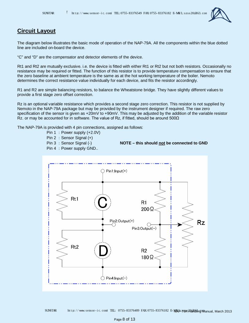
Circuit Layout The diagram below illustrates the basic mode of operation of the NAP-79A. All the components within the blue dotted line are included on-board the device. “C” and “D” are the compensator and detector elements of the device. Rt1 and Rt2 are mutually exclusive. i.e. the device is fitted with either Rt1 or Rt2 but not both resistors. Occasionally no resistance may be required or fitted. The function of this resistor is to provide temperature compensation to ensure that the zero baseline at ambient temperature is the same as at the hot working temperature of the boiler. Nemoto determines the correct resistance value individually for each device, and fits the resistor accordingly. R1 and R2 are simple balancing resistors, to balance the Wheatstone bridge. They have slightly different values to provide a first stage zero offset correction. Rz is an optional variable resistance which provides a second stage zero correction. This resistor is not supplied by Nemoto in the NAP-79A package but may be provided by the instrument designer if required. The raw zero specification of the sensor is given as +20mV to +90mV. This may be adjusted by the addition of the variable resistor Rz. or may be accounted for in software. The value of Rz, if fitted, should be around 500Ω The NAP-79A is provided with 4 pin connections, assigned as follows:
Pin 1 :Power supply (+2.0V) Pin 2 :Sensor Signal (+) Pin 3 :Sensor Signal (-) NOTE – this should not be connected to GND Pin 4 :Power supply GND..
SUNSTAR传感与控制 http://www.sensor-ic.com/ TEL:0755-83376549 FAX:0755-83376182 E-MAIL:[email protected]
SUNSTAR自动化 http://www.sensor-ic.com/ TEL: 0755-83376489 FAX:0755-83376182 E-MAIL:[email protected]

NAP-79A Handling Manual, March 2013
Page 9 of 13
Results of Performance Tests
The information contained in this section is for guidance purposes only and should not be considered to be part of the specification of the
NAP-79A Gas Sensor for legal or warranty purposes.
Durability The NAP-79A sensor has been designed and tested vigorously to ensure that it can tolerate a range of arduous conditions: Storage in low temperature: Sensors have been stored at temperatures of -30°C for 1 month. Storage in high temperature: Sensors have been stored at temperatures of +80°C for 1 month. Tolerance to High Humidity: Sensors have been stored in 50°C and 98%RH for 48 hours. Prolonged Storage Time: Sensors have been stored for 6 months in normal ambient conditions. Catalyst Poison Resistance: Sensors have been exposed to 10ppm Hexamethyledisiloxane (HMDS), a commonly encountered silicone which is known to poison noble metal catalysts. After all of the above environmental conditions, the NAP-79A was tested for Span and Sensitivity. In all cases the sensors showed the following results:
Gas Concentration Working Temperature Result following Environmental Test
0 ppm (Air) 23°C Initial Value +/- 1.5mV 100°C Value at 23°C +/- 1mV 200°C Value at 23°C +/- 1mV
1000ppm CO / 500ppm H2 23°C Initial Value +/- 0.7mV 140°C Initial Value +/- 0.5mV
Tolerance to Temperature Transients (Heat Shock) Sensors have been stored at -30°C for 2 hours then suddenly transferred to an environment of 80°C degree C for 2 hours. This temperature cycle was repeated 700 times. Following the temperature cycling, all components and joins were examined very closely for signs of physical damage, including solder connections. The sensors were also tested for Zero and Gas Sensitivity. No significant effect was noted on the either the structure or the performance of the sensors. Tolerance to Vibration Sensors were subjected to a vibration of 10 Hz, Amplitude 5mm, 1G in all three planes X, Y and Z for 20 minutes. No effect on performance or structural integrity of the device was detected following the vibration. Tolerance to Corrosive Gases Sensors have been tested thoroughly for long periods in gases containing SO2. and NO2 gases. No significant effect on the performance of the sensor has been noted. Nemoto is confident that, at the levels encountered in normal flue gases, these gases will have no detrimental effect to the performance of the sensor.
SUNSTAR传感与控制 http://www.sensor-ic.com/ TEL:0755-83376549 FAX:0755-83376182 E-MAIL:[email protected]
SUNSTAR自动化 http://www.sensor-ic.com/ TEL: 0755-83376489 FAX:0755-83376182 E-MAIL:[email protected]

NAP-79A Handling Manual, March 2013
Page 10 of 13
Zero drift with power supply variation The specification for the power supply for the NAP-79A sensor is 2.0V +/- 0.05V. It is important that the power supply used is reliable and drift free, because the zero offset of the sensor will change slightly if the power supply voltage drifts. The amount of zero drift associated with power supply drift also depends on the initial zero. Sensors with higher initial zero offsets also tend to exhibit higher levels of zero drift with power supply drift. To illustrate this, the plots below represent the zero drift with changing power supply voltage, with sensors adjusted to give different zeros offsets using the optional variable resistor Rz in the circuit on page 7. The same three sensors were used for each plot.
The upshot of this is that to achieve the most accurate performance in terms of zero stability, either great care should be taken to ensure that the voltage supplied to the sensor is stable, reliable and relatively drift free, or if the power supply is likely to drift significantly during operation. The resulting zero drift can be reduced to acceptable levels by the deployment of an optional variable resistor Rz on page 7, to adjust the zero offset locally, ideally to around 30mV.
-10
-5
0
5
10
1.9 2.0 2.1
Zero
Dri
ft (m
V)
Power supply (V)
With zero adjusted to 120mV
-10
-5
0
5
10
1.9 2.0 2.1
Zero
Dri
ft (m
V)
Power supply (V)
With zero adjusted to 80mV
-10
-5
0
5
10
1.9 2.0 2.1
Zero
Dri
ft (m
V)
Power supply (V)
With zero adjusted to 30mV
-10
-5
0
5
10
1.9 2.0 2.1
Zero
Dri
ft (m
V)
Power supply (V)
With zero adjusted to 20mV
SUNSTAR传感与控制 http://www.sensor-ic.com/ TEL:0755-83376549 FAX:0755-83376182 E-MAIL:[email protected]
SUNSTAR自动化 http://www.sensor-ic.com/ TEL: 0755-83376489 FAX:0755-83376182 E-MAIL:[email protected]

NAP-79A Handling Manual, March 2013
Page 11 of 13
Initial Start-up time and optional Heat Cleaning Cycle On initial power-up, the NAP-79A sensor will normally stabilize to a workable zero offset within 2 minutes. However, when powered-up for the first time following storage or a long period of inactivity, catalytic type gas sensors can sometimes take several hours to completely stabilize to their final zero offset point. For the majority of applications the initial stabilization time, even after long periods of storage, presents no problem since the zero stability after 120 seconds is within acceptable limits. However, if very high accuracy is required immediately following initial power-up, the stabilization of the sensor can be hastened by the application of a higher power supply (2.75V is recommended) for the first 30 seconds of operation, followed by the normal operating power supply. This “Heat Cleaning Cycle” will result in the sensor reaching its final zero reading more quickly than if it had the operating voltage applied only. The plot below illustrates the initial stabilization of sensors when powered for the first time following 30 days of normal storage. For this experiment the sensors were fitted with the optional resistor Rz (see page 7) and the zeros were adjusted to approximately 30mV. It can be seen that by using a heat cleaning cycle the gain in initial stabilization time is very slight and for most purposes the heat cleaning option gives little benefit.
20
25
30
35
40
0 50 100 150 200
Time (sec.)
Out
put
voltag
e (m
V)
←With heat cleaning for 30sec.
↑Without heat cleaning
SUNSTAR传感与控制 http://www.sensor-ic.com/ TEL:0755-83376549 FAX:0755-83376182 E-MAIL:[email protected]
SUNSTAR自动化 http://www.sensor-ic.com/ TEL: 0755-83376489 FAX:0755-83376182 E-MAIL:[email protected]

NAP-79A Handling Manual, March 2013
Page 12 of 13
Long Term Stability and Periodic zero correction The following plots represent the typical long term stability of the NAP-79A in a real working situation within a water heating boiler: Zero Offset:
Gas Sensitivity:
It can be seen that although the Gas Sensitivity of the sensor does not change significantly during the sensors lifetime in a real working situation, the zero offset does drift with time. However, this can easily be compensated for in the software of the appliance by carrying out a routine zero correction calibration during periods where the force ventilation of the flue is running but the burner is inactive, ensuring that no combustion gases are in the flue of the boiler during this procedure. This zero adjustment could be carried out, for example, whenever the appliance is switched on, just before the Burner is ignited.
-10.00
-8.00-6.00
-4.00
-2.000.00
2.00
4.00
6.008.00
10.00
0 5000 10000 15000 20000
Total combustion time (hrs.)
Zero
off
set
drift
in a
ir (
mV
)
Sample number : 4
0.000
2.000
4.000
6.000
8.000
0 5000 10000 15000 20000
Total combustion time (hrs.)
Gas s
ensitiv
ity in
CO
1000ppm
+H
2 5
00ppm
at
200 d
egre
e C
(m
V)
Sample number : 4
SUNSTAR传感与控制 http://www.sensor-ic.com/ TEL:0755-83376549 FAX:0755-83376182 E-MAIL:[email protected]
SUNSTAR自动化 http://www.sensor-ic.com/ TEL: 0755-83376489 FAX:0755-83376182 E-MAIL:[email protected]
NAP-79A Handling Manual, March 2013
Page 13 of 13
Notes for Designers.
1) Sensor Fault Diagnosis: It is recommended that the sensor is monitored for the unlikely event of an open-circuit or short circuit-fault during the lifetime of the appliance. In the case of an open-circuit fault, the zero offset signal of the sensor will change to close to either -1V or +1V In the case of a short circuit fault, the sensor’s zero offset signal will change to either 0V or 2V. It is therefore recommended that if the zero offset voltage changes to less than 0V (i.e. a negative value) or more than 150mV, then the appliance should signal a fault and the sensor should be replaced.
2) Mounting Position of the Sensor: The optimum position of the sensor is a matter for the appliance designer and Nemoto does not prohibit positioning of the sensor in any orientation or position within the flue, provided the sensor is operating within its environmental specification. However, it is recommended that the sensor is mounted on a vertical wall of the flue, since it is in this orientation that all Nemoto’s specification tests are performed. If necessary, the sensor should be provided with gasket seal to ensure that flue gases do not escape from the flue. The position of the sensor should be chosen to maximise its sensitivity and response time, whilst avoiding turbulent flow of gas at the sensor during operation if possible. The sensor should also be as far away as possible from other electrical parts of the appliance to minimise interference and RF electrical noise in the sensor signal. In many cases the best mounting position of the sensor will be determined by trial and error.
3) To avoid the potential of damage to the sensor by undue vibration, it is recommended that the sensor is not fitted to the appliance using power driven tools.
4) It is recommended that the sensor is permanently energised. This means that even when the appliance is not being used, the sensor remains energised and operating normally.
5) Since the detection of incomplete combustion by the sensor will result in the appliance being automatically shut down, it is recommended that a time weighted average measurement is used to verify the signal from the sensor. This will eliminate the slim possibility of false alarms caused by electrical noise spikes from pumps, switches etc within the appliance.
SUNSTAR传感与控制 http://www.sensor-ic.com/ TEL:0755-83376549 FAX:0755-83376182 E-MAIL:[email protected]
SUNSTAR自动化 http://www.sensor-ic.com/ TEL: 0755-83376489 FAX:0755-83376182 E-MAIL:[email protected]