dedicated controls - grundfos
TRANSCRIPT

GRUNDFOS INSTRUCTIONS
Dedicated ControlsService instructions

2 / 60
Contents
1. Symbols used in this document................................................................................................ 32. Identification ............................................................................................................................... 32.1 Dedicated Controls ..................................................................................................................................... 32.2 CU 361........................................................................................................................................................ 52.3 IO 351B....................................................................................................................................................... 62.4 Separate components................................................................................................................................. 72.5 Control cabinet............................................................................................................................................ 92.6 Environmental conditions and connection ................................................................................................ 102.7 Examples of control variants..................................................................................................................... 112.8 CU 361 control panel ................................................................................................................................ 122.9 Menu overview.......................................................................................................................................... 123. Overview of inputs and outputs of control unit/modules ..................................................... 143.1 Functions of terminals............................................................................................................................... 143.2 CU 361 terminals ...................................................................................................................................... 173.3 IO 351B terminals ..................................................................................................................................... 183.4 IO 111 terminals ....................................................................................................................................... 204. Configuration ............................................................................................................................ 224.1 Necessary equipment ............................................................................................................................... 224.2 Configuration of Dedicated Controls......................................................................................................... 225. Documentation supplied with Dedicated Controls................................................................ 276. PC Tool ...................................................................................................................................... 276.1 Connection of PC to Dedicated Controls .................................................................................................. 277. Fieldbus communication module............................................................................................ 287.1 SCADA system......................................................................................................................................... 287.2 Data communication ................................................................................................................................. 287.3 Fitting the CIM module.............................................................................................................................. 348. General settings, CU 361 ......................................................................................................... 368.1 Display language ...................................................................................................................................... 369. Fault finding .............................................................................................................................. 369.1 Power supply ............................................................................................................................................ 369.2 External control, data collection, SCADA systems ................................................................................... 369.3 Pumps....................................................................................................................................................... 3610. Fault finding tools..................................................................................................................... 3710.1 CU 361 display ......................................................................................................................................... 3710.2 System...................................................................................................................................................... 3910.3 Specific pump ........................................................................................................................................... 4010.4 GSM/GPRS .............................................................................................................................................. 4110.5 Float switch status .................................................................................................................................... 4210.6 Mixer ......................................................................................................................................................... 4310.7 Electrical overview.................................................................................................................................... 4411. Alarms and warnings ............................................................................................................... 4711.1 Alarm indicators ........................................................................................................................................ 4711.2 Alarm settings........................................................................................................................................... 4812. How to trace an alarm .............................................................................................................. 5012.1 Menu Status.............................................................................................................................................. 5012.2 Menu Alarm .............................................................................................................................................. 5012.3 Password protection ................................................................................................................................. 5112.4 R100 ......................................................................................................................................................... 5213. Fault finding by means of fault codes .................................................................................... 5313.1 Alarm list (system) .................................................................................................................................... 5313.2 Alarm list (pump)....................................................................................................................................... 5513.3 Alarm list (mixer)....................................................................................................................................... 5613.4 Alarm list (combi alarms) .......................................................................................................................... 5613.5 Alarm list (IO 111 belongs to a pump) ...................................................................................................... 56

1. Symbols used in this document
2. IdentificationThis section shows the nameplates, the type keys and the codes that can appear in a variant code.
2.1 Dedicated Controls
2.1.1 Nameplate
Fig. 1 Nameplate, Dedicated Controls
WarningIf these safety instructions are not observed, it may result in personal injury!
CautionIf these safety instructions are not observed, it may result in malfunction or damage to the equipment!
Note Notes or instructions that make the job easier and ensure safe operation.
Note As codes can be combined, a code position may contain more than one code (letter).
TM04
379
0 50
08
Pos. Description Pos. Description
1 Type designation 10 Number of fixed-speed pumps2 Model 11 Imax., relay output3 Serial number 12 Vmax., relay output4 Mains supply 13 Order number5 Power consumption 14-17 Options6 Fuse 18 Enclosure class7 Tamb. 19 Weight in kg8 Vcontact max. 20 CE-mark9 Icontact max. 21 Country of origin
Type:
Model:
Serial No:
Order No.:
Options:
IP
Weight: kg
Made in
1
2
3
4
8 9
10
17
Mains supply: Power consumption: W
Fuse: A TAMB: Cº
VCONTACT :MAX. V ICONTACT :MAX. A
No. of Fixed speed pumps:
Imax Vmax
Relay output: 11 12
13
19
20
18
21
14 15 16
6 7
5
96
81
78
67
3 / 60
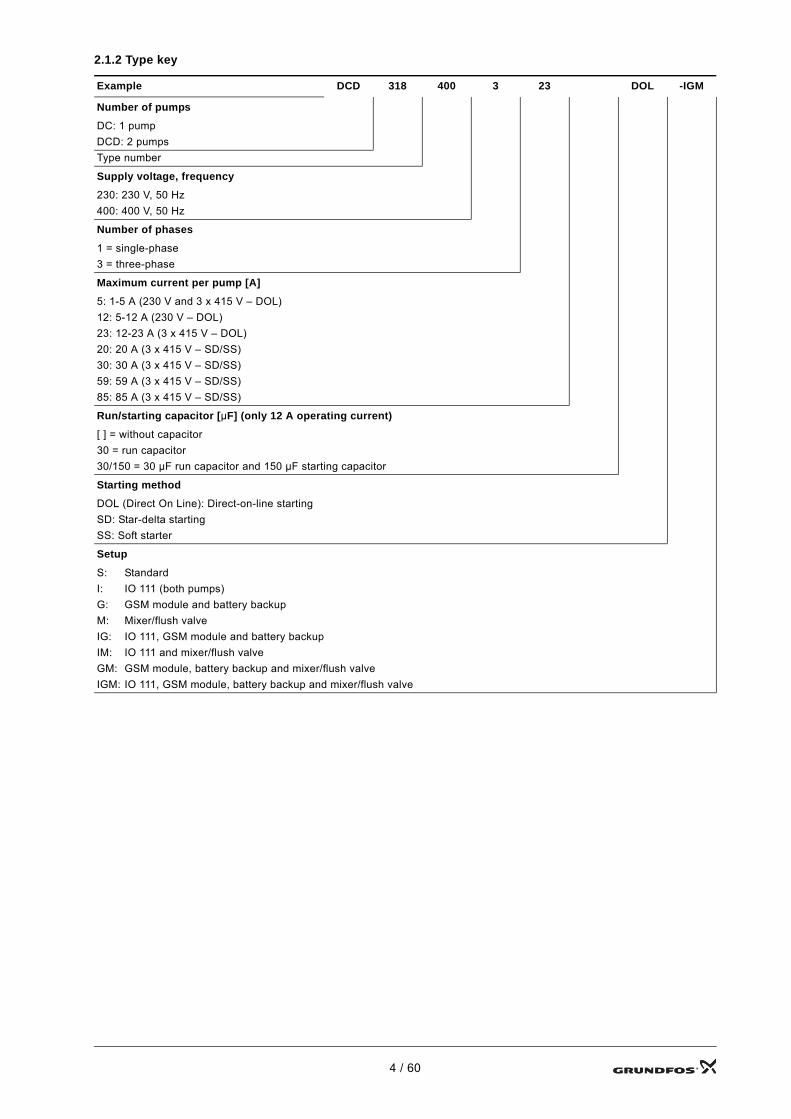
2.1.2 Type key
Example DCD 318 400 3 23 DOL -IGM
Number of pumps
DC: 1 pumpDCD: 2 pumpsType number
Supply voltage, frequency
230: 230 V, 50 Hz400: 400 V, 50 Hz
Number of phases
1 = single-phase3 = three-phase
Maximum current per pump [A]
5: 1-5 A (230 V and 3 x 415 V – DOL)12: 5-12 A (230 V – DOL)23: 12-23 A (3 x 415 V – DOL)20: 20 A (3 x 415 V – SD/SS)30: 30 A (3 x 415 V – SD/SS)59: 59 A (3 x 415 V – SD/SS)85: 85 A (3 x 415 V – SD/SS)
Run/starting capacitor [µF] (only 12 A operating current)
[ ] = without capacitor30 = run capacitor30/150 = 30 µF run capacitor and 150 µF starting capacitor
Starting method
DOL (Direct On Line): Direct-on-line startingSD: Star-delta startingSS: Soft starter
Setup
S: StandardI: IO 111 (both pumps)G: GSM module and battery backupM: Mixer/flush valveIG: IO 111, GSM module and battery backupIM: IO 111 and mixer/flush valveGM: GSM module, battery backup and mixer/flush valveIGM: IO 111, GSM module, battery backup and mixer/flush valve
4 / 60

2.2 CU 361
2.2.1 Nameplate The CU 361 can be identified by means of the nameplate on the back. See fig. 2.
Fig. 2 CU 361 nameplate
2.2.2 Type key
The CU 361 has a label for backup battery. See fig. 3.
Fig. 3 Label for backup battery
Fig. 4 Protective earth terminal
TM04
045
3 06
08
Pos. Description
1 Type designation2 Product number and version number3 Serial number4 Production code (year, week) 5 Rated voltage, frequency and power
Code Description CU 3 6 1
CU Control unit36 Controller series1 Model number
TM04
236
7 24
08
WarningRemove the battery before starting work on the CU 361.
TM00
582
7 34
08
Type
Made in Thailand
96
16
17
50
Product No.
UN
Serial No.
P.c.
!OPEN TYPE PROCESS
CONTROL EQUIPMENT
100-240 Vac 50/60Hz - Max. 22W
CU 361
96787482 - VO1
1 2
4
5
3
0536
0811
30 XP
12V dc
Battery powered
0V 12V
96
80
19
50
5 / 60

2.3 IO 351B
2.3.1 Nameplate
Fig. 5 Nameplate, IO 351B
2.3.2 Type key
TM03
101
7 22
05
Pos. Description
1 Type designation2 Product number and version number
3 Permissible supply voltage, frequency and maximum power consumption
4 Production code (year, week)5 Serial number
Code Description IO 3 5 1 B
IO Input/output module35 Controller series1 Model number
BFor pumps with fixed-speed and pumps controlled by external frequency converters or as input/output module
Type
Made in Denmark
96
16
17
50
Product No.
UN
Serial No.
P.c.
100-240 Vac 50/60Hz - max. 9W
IO 351B
96161730 - VO1
!30 XP
OPEN TYPE PROCESS
CONTROL EQUIPMENT
3
412
5
6 / 60

2.4 Separate components
Component Description Functions Product number
CU 361
GrA
658
8
The CU 361 is the 'brains' of the Dedicated Controls system and is mounted in the front of the control cabinet.The CU 361 can control and monitor one or two Grundfos wastewater pumps. The pumps can drain a pit using built-in draining algorithms. The algorithms are based on a water level measured by float switches or an analog level sensor.
CU 361 inputs and outputs:• GENIbus communication
(RS-485)• 3 analog inputs for connection to
sensors with current (0-20 mA/4-20 mA) or voltage (0-10 V)
• 3 digital inputs• 2 digital relay outputs, 240 VAC,
2 A• Connection to battery backup
(UPS) (optional)• Ethernet connection (VNC)• Connection to fieldbus CIM
modules (CIM = Communication Interface Module): – CIM 200 (Modbus via RS-485)– CIM 250 (Modbus and SMS via
GSM/GPRS)– CIM 270 (GRM)
(GRM = Grundfos Remote Management).
96787482
IO 351B
TM03
211
0 37
05
The IO 351B is a general I/O module.The IO 351B communicates with the CU 361 via GENIbus.Via the IO 351B inputs and outputs, the CU 361 controls the pumps according to the built-in algorithms.
IO 351B inputs and outputs:• GENIbus communication
(RS-485)• 2 analog inputs for connection to
sensors with current (0-20 mA/4-20 mA) or voltage (0-10 V)
• 9 digital inputs• 7 digital outputs, 240 VAC, 2 A• 4 PTC inputs.
96161730
IO 111
TM03
081
9 05
05
The IO 111 is a protection module for a Grundfos wastewater pump.The IO 111 has inputs for digital and analog pump sensors and can stop the pump if a sensor indicates a pump fault. The IO 111 is connected to the CU 361 and allows the monitoring of several sensors.
IO 111 inputs and outputs:• 1 digital input for moisture in
motor• 1 digital input for water-in-oil
detection• 1 digital input for high motor
temperature• 1 analog input for insulation
resistance• 1 analog input for stator
temperature• 1 digital output for alarm relay• 1 digital output for warning• 1 digital output for moisture-in-
motor alarm• 1 digital output for stator
temperature alarm• 1 digital output for insulation
resistance alarm.
96575362
7 / 60

CIM 200
GrA
612
0
The CIM 200 is a Grundfos communication interface module used for the fieldbus protocol Modbus RTU. The CIM 200 is to be fitted in the CU 361 control unit. The CIM 200 is used to communicate with a Modbus RTU network.
The CIM 200 module has terminals for the Modbus connection. DIP switches are used to set parity and line termination. Two hexadecimal rotary switches are used to set the Modbus address. Two LEDs are used to indicate the actual status of the CIM 200. One LED is used for internal communication, and the other is used to indicate Modbus communication status.
96824796
CIM 250TM
04 4
029
0609
The CIM 250 is a Grundfos communication interface module used for GSM/GPRS communication. The CIM 250 is to be fitted in the CU 361 control unit. The CIM 250 is used to communicate via a GSM network.
The CIM 250 module has a SIM-card slot and an SMA connection to the GSM antenna. The CIM 250 also has an internal backup battery. Two LEDs are used to indicate the actual status of the CIM 250. One LED is used for internal communication, and the other is used to indicate GSM/GPRS communication status.
96824795
CIM 270
TM04
402
9 06
09
The CIM 270 is a Grundfos communication interface module used in Grundfos Remote Management. The CIM 270 is to be fitted in the CU 361 control unit. The CIM 270 establishes communication between the CU 361 control unit and the Grundfos Remote Management system, thereby allowing the CU 361 to be monitored and controlled remotely. The CIM 270 uses GSM/GPRS communication.
The CIM 270 module has a SIM-card slot and an SMA connection to the GSM antenna. The CIM 270 also has an internal backup battery. Two LEDs are used to indicate the actual status of the CIM 270. One LED is used for internal communication, and the other is used to indicate GSM/GPRS communication status.
96898815
Component Description Functions Product number
8 / 60

2.5 Control cabinet
Cabinet Description Functions
Control cabinet
GrA
627
0
The control cabinet is delivered with all necessary components, including battery backup. Different types of control cabinets are available, depending on functions and network.The control cabinet is designed for installation in a control cabinet for outdoor use.Note: The main switch and backup fuses have to be installed externally.
Digital input• Energy measurement*• Volume measurement*• Motor protection, pump 1• Motor protection, pump 2• Relay resetting• External fault• Common phase error• Alarm relay resetting• Contactor feedback, pump 1• Contactor feedback, pump 2• Contactor feedback, mixer• Auto/On/Off, pump 1• On/Off, pump 1• Auto/On/Off, pump 2• On/Off, pump 2• Float switch 1• Float switch 2• Float switch 3• Float switch 4• Float switch 5• Too high motor temperature**• Moisture in motor**• PTC, pump 1• Klixon, pump 1• PTC, pump 2• Klixon, pump 2.Analog input• Pressure sensor*• Ultrasonic sensor*• Flow rate*• Motor current, pump 1*• Motor current, pump 2*• Water in oil, pump 1* or **• Water in oil, pump 2* or **• User-defined sensor 1*• User-defined sensor 2*• User-defined sensor 3*• Insulation resistance**• Stator temperature**Digital output• Pump 1, start• Pump 2, start• Mixer, start• User-defined relay• High-level alarm• Urgent alarms• All alarms• All alarms and warnings• User-defined alarms• Alarm relay**• Warning**• Moisture-in-motor alarm**• Stator temperature alarm**• Insulation resistance alarm**Communication• SMS and Modbus GSM/GPRS***• Modbus-wired****
* External sensor required** Only via the IO 111*** Via the CIM 250 GSM module**** Via the CIM 200 Modbus module
9 / 60

2.6 Environmental conditions and connection
2.6.1 Ambient temperature–20 °C to +50 °C.
2.6.2 Relative air humidityMaximum 95 %.
2.6.3 Mains supply, overload protection, fusesSee Grundfos wiring diagrams (technical data) supplied with Dedicated Controls.
10 / 60

2.7 Examples of control variants
One pump with two float switches One or two pumps with three float switches
One or two pumps with four float switches
TM02
811
4 47
03
TM02
829
9 49
03
TM02
830
0 49
03
One or two pumps with five float switches
One or two pumps with analog sensor
One or two pumps with analog sensor and mixer
TM02
830
1 47
03
TM02
830
5 17
04
TM04
295
5 34
08
One or two pumps with analog sensor and safety float switches
One or two pumps with analog sensor, safety float switches and mixer
TM04
295
6 35
08
TM04
370
0 49
08
11 / 60

2.8 CU 361 control panel
2.9 Menu overview
TM04
359
3 47
08
Pos. Description
1 LCD display
2 Changes to next column in menu structure
3 Changes to help text
4 Goes up in lists
5 Goes down in lists
6 Increases the value of a selected parameter
7 Decreases the value of a selected parameter
8 Goes one display back
9 Goes back to the Status menu
10 Saves a value
11 Green indicator light (operation)12 Red indicator light (alarm)
Fig. 6 CU 361 13 Changes the contrast of the display
1. Status1.1 System1.2 Specific pump1.3 GSM/GPRS1.4 Float switch status1.5 Mixer1.6 Electrical overview
1.6.1 Analog inputs1.6.2 Digital inputs1.6.3 Digital outputs
2. Operation2.1 Overview2.2 Auto/On/Off pump control2.3 Start and stop levels2.4 Resetting alarm relays
3. Alarm3.1 Current alarms3.2 Alarm log
1
2
3
546789
1011
1213
CU 361
12 / 60

4. Settings4.1 Basic functions
4.1.1 Primary settings4.1.2 Pit configuration and flow calculation4.1.3 Pump delays4.1.4 Float switch functions
4.1.4 Drain function, one pump and two float switches4.1.4 Drain function, one pump and three float switches4.1.4 Drain function, one pump and four float switches4.1.4 Drain function, two pumps and three float switches4.1.4 Drain function, two pumps and four float switches4.1.4 Drain function, two pumps and five float switches4.1.4 Analog sensor with safety float switches
4.1.5 Out of operation
4.2 Advanced functions4.2.1 Anti-seizing4.2.2 Daily emptying4.2.3 Foam draining4.2.4 Mixer configuration4.2.5 Adjustment of counters4.2.6 Resetting alarm log4.2.7 Duty/standby
4.3 Communication settings4.3.1 Selecting communication module4.3.2 Ethernet4.3.3 GENIbus number4.3.4 SMS numbers4.3.5 SMS schedule4.3.6 SMS heartbeat message4.3.7 SMS authentication4.3.8 SIM card settings4.3.9 SCADA settings4.3.10 Interlock settings4.3.11 GPRS settings
4.4 I/O settings4.4.1 Analog inputs4.4.2 Digital inputs4.4.3 Digital outputs4.4.4 Counter inputs4.4.5 Alarm relays
4.5 Alarm settings4.5.1 System alarms4.5.2 Pump alarms4.5.3 Mixer alarms4.5.4 Combi alarms
4.6 General settings, CU 3614.6.1 Run configuration wizard again4.6.2 Display language4.6.3 Units4.6.4 Date and time4.6.5 Password4.6.6 Ethernet4.6.7 GENIbus number4.6.8 Software status
13 / 60

3. Overview of inputs and outputs of control unit/modules
3.1 Functions of terminals
3.1.1 CU 361
Fig. 7 Back of CU 361
Unit/module Digital input Analog input Relay output Communication Extra
CU 361 3 3 2 NO/NC
GENIbus master (RS-485) Ethernet (VNC)SMS and Modbus GSM/GPRS (via CIM 250)Modbus-wired (via CIM 200)
Battery backup 12 V input
IO 351B 9 + 4 PTC 7 NO GENIbus slave (RS-485) IO 111 3 (dedicated) 2 (dedicated) 5 (dedicated) GENIbus slave (RS-485)
TM04
206
4 49
08
Pos. Description
1 Nameplate2 Terminals for digital output relays3 Terminals for analog inputs4 Service connection 5 Ethernet (RJ45)6 Voltage indicator7 Terminals for digital inputs8 Terminals for backup battery9 Terminals for CIM module (optional)
10 Cable clamps for GENIbus connections11 Internal GENIbus connection12 Terminal for power supply13 Label for backup battery
0V 12V
14 / 60

3.1.2 IO 351B
Fig. 8 Terminal groups
The module can be divided into these groups:
3.1.3 Indicator lights on the IO 351B
Fig. 9 Indicator lights on the IO 351B
The IO 351B has a green and a red indicator light.
TM03
211
0 37
05
Group 1 Connection of power supplyGroup 2 Digital outputs 1-3
Group 3A, 3B, 3CDigital inputsAnalog inputs and outputsGENIbus
Group 4A, 4B Inputs for PTC sensor or thermal switchGroup 5 Digital outputs 4-7
TM03
113
1 11
05
Indicator lightsDescription
Green Red
Off. – The power supply is interrupted.Flashes slowly (1 Hz). – The module is ready for operation, but there is no communication yet.Permanently on. – The power supply is on, and the module is starting up.
Flashes quickly (5 Hz). – The module is ready for operation, and the IO 351B and CU 361 communicate.
– Flashing The IO 351B and R100 communicate.
5
3C4B
3B
2
4A
3A
1
Red Green
15 / 60
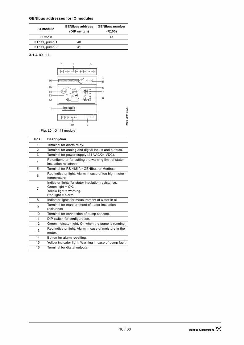
GENIbus addresses for IO modules
3.1.4 IO 111
Fig. 10 IO 111 module
IO moduleGENIbus address
(DIP switch)GENIbus number
(R100)
IO 351B 41IO 111, pump 1 40IO 111, pump 2 41
TM03
069
1 05
05
Pos. Description
1 Terminal for alarm relay.2 Terminal for analog and digital inputs and outputs.3 Terminal for power supply (24 VAC/24 VDC).
4 Potentiometer for setting the warning limit of stator insulation resistance.
5 Terminal for RS-485 for GENIbus or Modbus.
6 Red indicator light. Alarm in case of too high motor temperature.
7
Indicator lights for stator insulation resistance.Green light = OK.Yellow light = warning.Red light = alarm.
8 Indicator lights for measurement of water in oil.
9 Terminal for measurement of stator insulation resistance.
10 Terminal for connection of pump sensors.11 DIP switch for configuration.12 Green indicator light. On when the pump is running.
13 Red indicator light. Alarm in case of moisture in the motor.
14 Button for alarm resetting.15 Yellow indicator light. Warning in case of pump fault.16 Terminal for digital outputs.
Reset
PET1 T2 G1 A1 G2 A2 K1 K2 R1 R2
D1 D2 D3 D4 D5 D6 D7 D8
P1 P2 P3 P4 P5
A Y B
I1 I2 I3
ON DIP
1 2 3 4 5 6 7 8 9 10
1 2 3
910
45
67
8
11
12
15
16
1314
16 / 60

3.2 CU 361 terminals
Pos. Terminal Designation Data Diagram
1
L Connection to phase conductor
1 x 100-240 VAC ± 10 %, 50/60 HzN Connection to neutral
conductor
PE Connection to protective earth
2
A1 RS-485 AGENIbus(Fix the screen with a cable clamp.)Y1 RS-485 GND
B1 RS-485 B
Functional earth
3 Connection to external fieldbus, see installation and operating instructions for the CIM module.
40 V
Connection to battery Backup battery+12 VDC
5
10 DI1
Digital input11 GND12 DI213 GND14 DI3
All terminals (except mains terminals) must only be connected to voltages not exceeding 16 Vrms and 22.6 Vpeak or 35 VDC.
6Ethernet RJ45
External computing devices connected to the Ethernet connection must comply with the standards IEC 60950 and UL 60950.
7 GENIbus Service connection
8
47 +24 V Supply to sensor. Short-circuit-protected 30 mA.
50 +24 V Supply to sensor. Short-circuit-protected 30 mA.
51 AI1 Input for analog signal, 0-20/4-20 mA or 0-10 V
53 +24 V Supply to sensor. Short-circuit-protected 30 mA.
54 AI2 Input for analog signal, 0-20/4-20 mA or 0-10 V57 AI3
58 GND*All terminals (except mains terminals) must only be connected to voltages not exceeding 16 Vrms and 22.6 Vpeak or 35 VDC.
9
70 Relay 1 C71 Relay 1 NO72 Relay 1 NC73 Relay 2 C74 Relay 2 NO
75 Relay 2 NC
* GND is isolated from other earth connections.
L
N
CU 361
L
N
PE
AYB
CU 361 IO 351BA1Y1B1
14
13
12
10
11
57
54
53
50
51
58
1
23
47
74
73
72
70
71
75
17 / 60

3.3 IO 351B terminals
Group Terminal Designation Data Diagram
1
L Connection to phase conductor
1 x 100-240 VAC ± 10 %, 50/60 HzLN Connection to neutral
conductorN
Connection to protective earth
2
76 DO1, 2, 3 C
Relay contact, NOMaximum load: 240 VAC, 2 AMinimum load: 5 VDC, 10 mA
76 DO1, 2, 3 C77 DO1 NO79 DO2 NO
81 DO3 NO
3A
10 DI1
Digital input12 DI214 DI315 GND
All terminals (except mains supply terminals) must only be connected to voltages of maximum 16 Vrms and 22.6 Vpeak or 35 VDC.Fit jumpers instead of the external stops for which the controller is designed.
3A
53 +24 V Supply to sensor. Max. 50 mA.55 GND57 AI1 Input for analog signal,
0/4-20 mA or 0-10 V60 AI2All terminals (except mains supply terminals) must only be connected to voltages of maximum 16 Vrms and 22.6 Vpeak or 35 VDC.
3C
A RS-485 A
GENIbus (internal)(Fix the screen with a cable clamp.)
A RS-485 AY RS-485 GND*Y RS-485 GND*B RS-485 BB RS-485 B
Functional earth
4A
30 PTC 1Input for PTC sensor or thermal switch32 PTC 2
34 PTC 335 GND, PTC
Fit jumpers if no PTC sensor or thermal switch is connected.All terminals (except mains supply terminals) must only be connected to voltages of maximum 16 Vrms and 22.6 Vpeak or 35 VDC.
* GND is isolated from other earth connections.
L
N
IO 351B
L
N
PE
81
76
76
79
77
IO 351B
IO 351B
15
14
12
10
IO 351B
55
5760
53
AYB
CU 361IO 351B
A1Y1B1
IO 351B
32
34
35
30
18 / 60

3B
16 DI4 Digital input17 GND18 AO4 Analog output, 0-10 V20 DI5 Digital input21 GND22 AO5 Analog output, 0-10 V24 DI6 Digital input25 GND
26 AO6 Analog output
42 DI7Digital input44 DI8
46 DI947 GND
Fit jumpers instead of the external stops for which the controller is designed.
4B
36 PTC 4Input for PTC sensor or thermal switch38 PTC 5
40 PTC 641 GND, PTC
Fit jumpers if no PTC sensor or thermal switch is connected.All terminals (except mains supply terminals) must only be connected to voltages of maximum 16 Vrms and 22.6 Vpeak or 35 VDC.
5
82 DO4 NO
Relay contact
83 DO4 C83 DO4 C84 DO5 NO85 DO5 C85 DO5 C86 DO6 NO87 DO6 C87 DO6 C88 DO7 NO89 DO7 C
Group Terminal Designation Data Diagram
IO 351B16171820212223242526
44
46
47
42
IO 351B
38
40
41
36
IO 351B8283838485858687878889
19 / 60
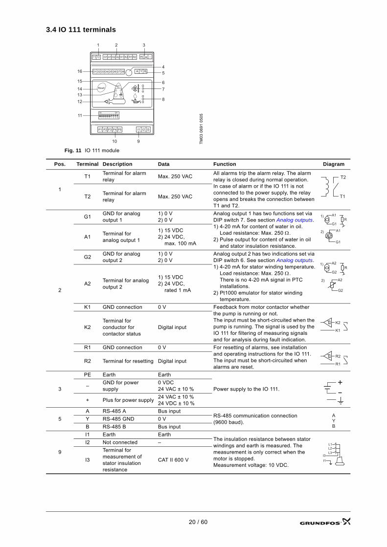
3.4 IO 111 terminals
Fig. 11 IO 111 module
TM03
069
1 05
05
Pos. Terminal Description Data Function Diagram
1
T1 Terminal for alarm relay Max. 250 VAC All alarms trip the alarm relay. The alarm
relay is closed during normal operation.In case of alarm or if the IO 111 is not connected to the power supply, the relay opens and breaks the connection between T1 and T2.
T2 Terminal for alarm relay Max. 250 VAC
2
G1 GND for analog output 1
1) 0 V2) 0 V
Analog output 1 has two functions set via DIP switch 7. See section Analog outputs.1) 4-20 mA for content of water in oil.
Load resistance: Max. 250 Ω.2) Pulse output for content of water in oil
and stator insulation resistance.
A1 Terminal for analog output 1
1) 15 VDC 2) 24 VDC,
max. 100 mA
G2 GND for analog output 2
1) 0 V2) 0 V
Analog output 2 has two indications set via DIP switch 6. See section Analog outputs.1) 4-20 mA for stator winding temperature.
Load resistance: Max. 250 Ω.There is no 4-20 mA signal in PTC installations.
2) Pt1000 emulator for stator winding temperature.
A2 Terminal for analog output 2
1) 15 VDC 2) 24 VDC,
rated 1 mA
K1 GND connection 0 V Feedback from motor contactor whether the pump is running or not.The input must be short-circuited when the pump is running. The signal is used by the IO 111 for filtering of measuring signals and for analysis during fault indication.
K2Terminal for conductor for contactor status
Digital input
R1 GND connection 0 V For resetting of alarms, see installation and operating instructions for the IO 111.The input must be short-circuited when alarms are reset.
R2 Terminal for resetting Digital input
3
PE Earth Earth
Power supply to the IO 111.– GND for power supply
0 VDC24 VAC ± 10 %
+ Plus for power supply 24 VAC ± 10 % 24 VDC ± 10 %
5A RS-485 A Bus input
RS-485 communication connection (9600 baud).Y RS-485 GND 0 V
B RS-485 B Bus input
9
I1 Earth EarthThe insulation resistance between stator windings and earth is measured. The measurement is only correct when the motor is stopped.Measurement voltage: 10 VDC.
I2 Not connected –
I3
Terminal for measurement of stator insulation resistance
CAT II 600 V
Reset
PET1 T2 G1 A1 G2 A2 K1 K2 R1 R2
D1 D2 D3 D4 D5 D6 D7 D8
P1 P2 P3 P4 P5
A Y B
I1 I2 I3
ON DIP
1 2 3 4 5 6 7 8 9 10
1 2 3
910
45
67
8
11
12
15
16
1314
T1
T2
G1
A1R
1)
G1
A12)
G2
A2R
1)
G2
A22)
K2
K1
R2
R1
+
A
Y
B
L1L2L3
I3I1
20 / 60

10
P1 Terminal for sensors in the pump Sensor input
Thermal switch or PTC sensor according to DIN 44081 and 44082.
P1 to P5 are used for the connection of sensors in the pump. All sensors in contact with phase voltage must be double-insulated according to EN 61010-1.
P2Terminal for power supply to sensors in the pump
15 V
P3 Terminal for sensors in the pump Sensor input
P4Terminal for power supply to sensors in the pump
15 V
P5 Terminal for sensors in the pump Sensor input
16
D1Terminal for alarm in case of too high stator temperature
Digital output24 VDCmin. 10 kΩ
Alarm in case of too high temperature in the stator windings. The output is closed during normal operation. If an alarm occurs, the connection is broken between D1 and D2.D2
GND for alarm in case of too high stator temperature
0 V
D3Terminal for alarm in case of moisture in the motor
Digital output24 VDCmin. 10 kΩ
Alarm in case of moisture in the motor part of the pump. The output is closed during normal operation. If an alarm occurs, the connection is broken between D3 and D4.D4
GND for alarm in case of moisture in the motor
0 V
D5Terminal for alarm in case of insulation fault
Digital output24 VDCmin. 10 kΩ
Alarm in case of too low insulation value between stator windings and earth. The output is closed during normal operation.If an alarm occurs, the connection is broken between D5 and D6.D6
GND for alarm in case of insulation fault
0 V
D7 Terminal for warningDigital output24 VDCmin. 10 kΩ
Warning. The output is closed during normal operation. If a warning occurs, the connection is broken between D7 and D8. The following warnings can occur:• communication warning• configuration warning• too much water in oil• stator insulation resistance below
warning limit.See also section 8. Indication in the installation and operating instructions for the IO 111 and section 3.1.3 Indicator lights on the IO 351B.
D8 GND for warning 0 V
Pos. Terminal Description Data Function Diagram
P1..P5
D1
D2
D3
D4
D5
D6
D7
D8
21 / 60

4. Configuration
4.1 Necessary equipmentThe following equipment is needed:• R100, SW version 14, Nov. 01, 2005 or later• PC Tools• PC Tool Link adapter.
4.2 Configuration of Dedicated ControlsThe configuration consists of three steps:• Setting the GENIbus number in the IO 351B module, if installed.
See section 4.2.1 Setting the GENIbus number in IO 351B modules, if installed.• Configuration of the CU 361 control unit.
Use the configuration wizard or the PC Tool WW Controls supplied on CD-ROM. See section 6. PC Tool.• Configuration of the IO 111 module, if installed.
Use the PC Tool Water Utility, DIP switches in section 4.2.3 or see the installation and operating instructions for the IO 111.
4.2.1 Setting the GENIbus number in IO 351B modules, if installedThis module must have a GENIbus number according to the following table:
To assign a GENIbus number to the IO 351B module, proceed as follows:1. Switch on the power supply to the Dedicated Controls.2. Switch on the R100 and point it at the IR window of the first IO 351B to establish connection.
Fig. 12 IR window of the IO 351B
3. Go to the first display "Number, IO 351" in the INSTALLATION menu with the R100. See fig. 13. Set the number of the module according to the above table.
Fig. 13 Menu INSTALLATION, "Number, IO 351"
4. Send the number to the module by pressing [OK] on the R100.
4.2.2 Configuration of the IO 111, if installedSee section 4.2.3 IO 111 settings.
Module number GENIbus numberA01 (IO 351B) 41
NoteIf there are more than one IO 351B module, move close to the IR window to make sure that the R100 only communicates with one module at a time.
TM03
997
2 47
07
TM04
378
8 50
08
22 / 60

4.2.3 IO 111 settings
PotentiometerThe warning limit for stator insulation resistance is set by means of a potentiometer (pos. 4). See fig. 10. The limit can be set between 10 and 1 MΩ .
Fig. 14 Potentiometer
DIP switchesThe IO 111 must be configured for the pump connected by means of the DIP switches (pos. 11). See fig. 10.
Fig. 15 DIP switch
A configuration alarm will be given • if the configuration does not correspond to the pump connected.• if the configuration fault is of safety-related importance. See section 8. Indication, point 6, in the installation
and operating instructions for the IO 111.A configuration warning will be given • if the configuration fault is of function-related importance. See section 8. Indication, point 15, in the installation
and operating instructions for the IO 111 and section 3.1.3 Indicator lights on the IO 351B.Switch 9 is not used.
Pump variantThe IO 111 must be set to the actual pump. In the pump type designation, there is an A or D.Example 1, internal wiring:SE - 1 80 80 40 A Ex 4 5 1DExample 2, external wiring:SE2.90.250.2250.4.S.496.Ex.S.5.13.C.Q.SThese letters (A and D in the examples) can be found on the pump nameplate and refer to the setting of DIP switches 1 and 2.
Note The alarm limit is 1 MΩ.
TM03
341
5 03
06TM
03 0
678
0505
NoteThe SM 111 cannot be used together with Dedicated Controls. The signals from the SM 111 will not be monitored.
Pump variant Description
Variant A Installation without SM 111.Sensors are connected directly to the IO 111.
Variant D
Installation without SM 111.All sensors are hardwired out of the pump. The IO 111 can be used for indication of water in oil and as PTC relay.
1 MΩ 10 MΩ
ON DIP
1 2 3 4 5 6 7 8 9 10
ON DIP
1 2 3 4 5 6 7 8 9 10
ON
1 2
ON
1 2
23 / 60

Address for bus communicationThe IO 111 can communicate with control systems via a bus connection. In connection with bus communication, the IO 111 is slave. As a control system must be able to identify the slave units with which it communicates, the IO 111 modules must have unique addresses. Addresses between 40 and 46 are set by means of the switches 3, 4 and 5. See table. If the DIP switches are set to bus configuration, the address of the IO 111 module is set from the control system via bus. The address can be selected between 32 and 231. As standard, the address is set to 231.
Address Description
40 Pump 1
41 Pump 2
42 Pump 3
43 Pump 4
44 Pump 5
45 Pump 6
46 Pump 7
Bus configurationThe address of the IO 111 is set from the control system via the bus connection.Default address: 231.
ON DIP
1 2 3 4 5 6 7 8 9 10
3 4 5
3 4 5
3 4 5
3 4 5
3 4 5
3 4 5
3 4 5
3 4 5
24 / 60

Analog outputsThe analog outputs of the IO 111 can be set to various types of output signal.
Bus protocolBy setting the bus protocol, the type of bus connection is chosen. GENIbus is a Grundfos standard protocol for Grundfos products. The Modbus protocol is used for communication between the IO 111 and a control unit from another supplier.
Analog output Description
Analog output 2:G2 and A2 (pos. 2)
Motor temperature4-20 mA, 0-180 °C0 mA = no sensor
Analog output 2:G2 and A2 (pos. 2)
Motor temperaturePt1000 emulator1000-1685 Ω, 0-180 °C
Analog output 1:G1 and A1 (pos. 2)
Water in oil4-20 mA, 0-20 %0 mA = water-in-oil sensor not fitted3.5 mA = alarm, air in oil chamber22 mA = warning, water content far outside the measuring
range
Analog output 1: G1 and A1 (pos. 2)
Water in oilPulse output: 0-20 %Maximum connection: 24 V, 100 mA
Status of output transistor
Pulse A, water in oil:0.5 - 3.66 s = 0-20 %10 s = water content far outside the measuring range
Pulse B, insulation resistance:0.5 s = 0 MΩ10.5 s = 20 MΩ
Bus protocol Description
GENIbus Grundfos standard protocol for communication between Grundfos products
ModbusSee www.grundfos.com, WebCAPS, Literature, Accessories, Accessories, electrical and Operating the IO 111 via Modbus, document number 96623373.
ON DIP
1 2 3 4 5 6 7 8 9 10
6
6
7
7
Time
Pulse BPulse A
Off
On
ON DIP
1 2 3 4 5 6 7 8 9 10
8
8
25 / 60

ATEX/IECEx protectionATEX/IECEx protection can be activated/deactivated by means of DIP switch 10.
4.2.4 CU 361 and IO 351 installation and operating instructionsSee WinCAPS or WebCAPS > Service > Dedicated Controls > CU 361 or IO 351 > Installation and operating instructions.
ATEX/IECEx protection Description
Deactivated
Activation of ATEX/IECEx protection enables additional alarms:• Main bearing temperature to high.
Default alarm temperature: 140 °C(installation with SM 111).
• Support bearing temperature to high.Default alarm temperature: 140 °C(installation with SM 111).
• Missing signal from bearing sensor(installation with SM 111).
• Missing signal from water-in-oil sensor• Communication alarm
(installation with SM 111).
Activated
ON DIP
1 2 3 4 5 6 7 8 9 10
10
10
26 / 60

5. Documentation supplied with Dedicated ControlsThe following documentation is supplied with the Dedicated Controls control cabinet.
Instructions• Safety instructions for Dedicated Controls (printed multilingual version)• Installation and operating instructions for Dedicated Controls (monolingual version on CD-ROM)• Supplement to installation and operating instructions for Dedicated Controls (printed version)• Installation and operating instructions for the CU 361 (multilingual version)• Installation and operating instructions for the IO 351 (multilingual version).
Other documentation on control cabinet• Electrical wiring diagrams• List of supplied components (parts list) and description of cable colours and dimensions as well as sizes of
backup fuses• Control cabinet layout.
6. PC ToolFor information about PC Tool, open the help function in the software.
6.1 Connection of PC to Dedicated ControlsFor the physical connection between the PC and Dedicated Controls, a Grundfos PC Tool Link is used. This converts the RS-485 used by Dedicated Controls to USB used by the PC. The PC Tool Link also provides a galvanic separation between Dedicated Controls and the PC.
Fig. 16 Connection of PC to Dedicated Controls using the PC Tool Link
USB cable PC Tool Link TTL cableA1 Y1 B110 11 12 13 14
70
71
72
73
74
75
50
51
53
54
57
58
DO1, C
DO1, NO
DO1, NC
DO2, C
DO2, NO
DO2, NC
+24V
AI 1
+24V
AI 2
AI 3
GND
DI
1
GN
D
DI
2
GN
D
DI
3
RS
48
5, A
RS
48
5,
GN
D
RS
48
5,
B
RS
48
5, A
RS
48
5,
GN
D
RS
48
5,
B
Lin
e
Neutr
al
PE
L NB Y A
Service plug
27 / 60

7. Fieldbus communication module
7.1 SCADA systemSee the installation and operating instructions for Dedicated Controls to set up communication to SCADA systems. See also section 7.2 Data communication or menu 4.3 in the CU 361.Grundfos does not supply SCADA systems. If it seems as if the SCADA system is faulty, we recommend you to contact the supplier.
7.1.1 CommunicationThe communication takes place via a Modbus module or a GSM/GPRS module. See section 7.2 Data communication.
7.2 Data communicationThe CU 361 must have a CIM module (CIM = Communication Interface Module) fitted to be able to transfer data to the SCADA system or to a mobile phone.Various CIM modules are available, depending on the type of network. The CIM module can be fitted directly in the CU 361. See section 7.3 Fitting the CIM module.For configuration of the CIM module, see the installation and operating instructions and the functional profile on the CD-ROM supplied with the module.The user must select the type of communication module fitted before a network connection can be established.The following CIM modules can be fitted in the CU 361:• CIM 200 (Modbus via RS-485)• CIM 250 (Modbus and SMS via GSM/GPRS)• CIM 270 (GRM)
(GRM = Grundfos Remote Management).
Fig. 17 Example, selection of CIM module and communication
Note The SCADA system integrator can order a functional profile from Grundfos.
Dis
play
_4.3
28 / 60

7.2.1 Modbus network
CIM 200 (Modbus via RS-485)The CIM 200 module transfers data to/from the CU 361 and the local Modbus network. See fig. 18.
Fig. 18 Example, CIM 200
CIM 250 (Modbus and SMS via GSM/GPRS)The CIM 250 transfers data to/from the CU 361 and a GSM/GPRS network. See fig. 19.The CIM 250 can send/receive SMS messages to/from one or more mobile phones. The CIM 250 can also send data to a remote SCADA system.
Fig. 19 Example, CIM 250
TM04
322
1 39
08
Note A series of system parameters must be set before SMS messaging can be used.
TM04
369
7 49
08
CU 361(CIM 200 built-in)
Modbus network
SCADA
CU 361(CIM 250 built-in)
SCADA
GSM antenna
Mobile phone
29 / 60

7.2.2 CIM 270 (GRM)The CIM 270 module is used to link with Grundfos Remote Management.
Fig. 20 Example, CIM 270
7.2.3 EthernetEthernet is the most widely used standard for local networks (LAN). The standardisation of this technology has created some of the easiest and cheapest ways of creating communication between electrical units, for instance between computers or between computers and control units.The web server of the CU 361 makes it possible to connect a computer to the CU 361 via an Ethernet connection (Ethernet crossover cable). The user interface can thus be exported from the CU 361 to a computer so that the CU 361 and consequently the Dedicated Controls system can be remotely monitored and controlled. See figs 21 and 22.
In order to use the web server, the user must know the IP address of the CU 361. All network units must have a unique IP address to communicate with each other. The IP address of the CU 361 from factory is 192.168.0.102.Alternatively to the factory-set IP address, it is possible to use a dynamic assignment of IP address. This is possible by activating a DHCP (Dynamic Host Configuration Protocol) either directly in the CU 361 or via the web server.
Fig. 21 Example, Ethernet connection
TM04
369
8 49
08
NoteGrundfos recommends that the system administrator is contacted to arrange security protection for the CU 361 connection.
TM04
321
8 39
08
CU 361(CIM 270 built-in)
GRM WebAccess
GSM antenna
Mobile phone
GRM server
Ethernet crossover cable
CU 361
30 / 60

Fig. 22 Example, internet connection
Dynamic assignment of an IP address for the CU 361 requires a DHCP server in the network. The DHCP server assigns a number of IP addresses to the electrical units and makes sure that two units do not receive the same IP address.A standard internet browser is used for connection to the web server of the CU 361. If the user wants to use the factory-set IP address, no changes are required in the menu display. Open the internet browser, and enter the IP address of the CU 361.Now open the browser, and enter the CU 361 "Host name" (Default: CU361) instead of the IP address. The internet browser will try to connect to the CU 361. The host name can be read in the display, but can only be changed using a PC tool or via a web browser.
This is the first menu display seen when the CU 361 connects.
Fig. 23 Connecting to the CU 361
Factory settingUsername: adminPassword: adminWhen username and password have been entered, a Java Runtime Environment application starts up in the CU 361, provided that it has been installed on the computer in question. If this is not the case, but the computer is connected to the internet, then use the link on the screen to download and install the Java Runtime Environment application.
TM04
369
9 49
08
Note DHCP requires a host name.
TM03
204
8 35
05
Ethernet cable for internet connection
CU 361
PC with access to the CU 361 via the internet
31 / 60

Fig. 24 Display with link to JavaScript® application
The Java Runtime Environment application transfers the CU 361 user interface (including display and panel functions) onto the computer screen. The CU 361 can now be controlled from the PC.
Fig. 25 Network setting
Change of network settingWhen the connection to the web server of the CU 361 has been established, it is possible to change the network setting.
Fig. 26 Change of network setting
1. Click the icon "Network admin".2. Enter the changes.3. Click [Submit] to enable the changes.
TM03
204
9 35
05
TM03
320
4 39
08TM
03 2
050
3505
32 / 60

Change of password
Fig. 27 Change of password
1. Click the icon "Change password".2. Enter the new password.3. Click [Submit] to enable the new password.
7.2.4 GENIbusBy installing an external GENIbus module (CIM 050), it is possible to connect a CU 361 to an external network. The connection can be established via a gateway. For more information, contact Grundfos.
TM03
205
1 35
05
33 / 60

7.3 Fitting the CIM moduleThe CIM module must be fitted by authorised personnel.
Fit the CIM module as follows:1. Remove the screw in the back cover of the CU 361. See fig. 28.
Fig. 28 Removing the screw holding the back cover
2. Remove the cover. Place the cover on a plane surface, and push out the marked knockout using a screwdriver or a similar tool. See fig. 29.
Fig. 29 Opening the back cover and removing the knockout
WarningSwitch off the power supply to the CU 361 before fitting the CIM module.
WarningElectrostatic discharge (ESD) must be avoided when fitting the CIM module, for instance by wearing an antistatic wrist strap as shown in fig. 30.
TM04
240
2 25
08TM
04 2
403
2508
34 / 60

3. Fit the CIM module. See fig. 30.
Fig. 30 Fitting the CIM module
4. Place the labels supplied with the CIM module on the back cover. See fig. 31.
Fig. 31 Placing the new labels on the back cover
5. Refit the back cover to the CU 361, and secure it with the mounting screw. See fig. 32.
Fig. 32 Refitting the back cover
TM03
222
7 39
05
TM04
258
6 27
08
TM04
258
7 27
08
Type:
Kit Funct. module - Geni/RS485Op
Prod. No.
Version V01 Serial No.
P. C. 0538
9854
CIM
250
GS
M
CIM 250
96824795
35 / 60

8. General settings, CU 361
8.1 Display languageIn this menu, the CU 361 display language is selected. In connection with service, it is easy to change over to the service language, using the function "Change language to the service language (English)".
9. Fault finding
9.1 Power supplySee the system wiring diagram and system documentation.
9.2 External control, data collection, SCADA systemsSee the system wiring diagram and system documentation.
9.3 PumpsSee the documentation for the connected pump(s).
For example via WinCAPS, WebCAPS or service instructions for the connected Grundfos pump(s).
Path: Settings>General settings, CU 361>
Dis
play
_4.6
DescriptionOther functions related to CU 361• Display language.
36 / 60

10. Fault finding tools
10.1 CU 361 display
10.1.1 StatusThe first status display is shown below. This display appears when the Dedicated Controls is switched on, and it appears when the buttons of the control panel have not been touched for 15 minutes.The status display is the main opening display of the CU 361.
An alarm is shown as an alarm bell next to the unit that caused the alarm. When the system registers an alarm or warning, the following will happen:• An alarm bell is shown on the right of the upper status line.• The red indicator light on the control panel lights up.• "Current alarms" appear as the first line below the pit graphics.• The alarm relay operates.• The indication is maintained as long as the system has an active alarm. An alarm is active until it has been
reset, either automatically or manually via "Current alarms" in the status display.• An alarm cannot be reset until the fault causing the alarm has been corrected.
Example: An overtemperature alarm cannot be reset until the pump has cooled.
NoteIf the buttons on the control panel have not been activated for 15 minutes, the CU 361 automatically reverts to this display.
Note The display shown below should be considered as an example.
Path: Status>
Dis
play
_1
DescriptionOptions:• Current alarms
– See current alarms. The line is only active if there is one or more active alarms.
• System– See operating parameters for the system.
• Pump 1– See operating parameters for pump 1.
• Pump 2– See operating parameters for pump 2.
The hand symbol indicates that the pump is manually controlled, i.e. the pump can only be started and stopped manually.
• Float switches– See current positions and status of the float switches.
• Mixer– See mixer status.
• Electrical overview– See actual values for analog and digital inputs as well as digital
outputs.Note: Float switches and mixer will only appear if they are installed in the system.
2
1 8
6
3 10
11
45
9
7
37 / 60

Key to display
Pos. Description
1 Lowest start level: If the water level rises above this level, the first pump will start. 2 Lowest stop level: If the water level falls below this level, both pumps will stop.3 The display shows that pump 1 is started. The bottom is a dotted/broken line.
4 The actual flow is measured by a flowmeter or with the help of level measurements and pit data. See installation and operating instructions for Dedicated Controls.
5 Alarm bell: The alarm bell is visible as long as there are active alarms. The red indicator light on the control panel has the same function.
6 The broken line moves up to symbolise flow. The line appears when one or both pumps are running.7 Shows the water level as falling or rising. 8 This value and the wavy line show the current water level in the pit.9 Mixer: The propeller rotates if the mixer is operating.
10 The display shows that pump 2 is stopped. The bottom is a thick, unbroken line.11 Pressure sensor symbol: The sensor is shown at the bottom of the pit and represents a standard pressure sensor.
38 / 60

10.2 SystemThis display shows the actual operating parameters of the system.
Description of operating parameters
Note The display shown below should be considered as an example.
Path: Status>System>
Dis
play
_1.1
DescriptionThe display shows an operating overview of the system.• Operating hours• Parallel-operation time• Overflow time• Overflow volume• Number of overflows• Total volume• Energy• Specific energy• GSM/GPRS.
Operating parameter Function
Operating hours Total number of system operating hours.Parallel-operation time The accumulated time in which more than one pump has been in operation. Overflow time Overflow duration.Overflow volume The estimated overflow volume, based on the latest flow calculation.Number of overflows The number of registered overflows.
Total volume
The accumulated volume of liquid removed.Note: Requires a flowmeter (analog or pulse measurement), or the volume is calculated using an analog sensor if the pit dimensions are known.For more pit configuration details, see installation and operating instructions for Dedicated Controls.
Energy Total amount of energy in kWh.
Specific energy
Shows the specific energy, indicating the efficiency of the pump to convert the electrical energy (measured in kWh) to pumped volumes (measured in m3). The specific energy is indicated in kWh/m3.To be able to make a satisfactory average measurement, the measuring interval is one hour.Note: Requires an energy meter (pulse input or analog input).
GSM/GPRS
GSM/GPRS modem status:• Ready• Invalid PIN code• Invalid PUK code• Invalid service centre• Insert SIM card• SIM card defective• Invalid SIM card• SIM busy.
39 / 60

10.3 Specific pumpThis display shows the actual operating parameters of pump 1.Many parameters will show a value only if the relevant sensors and modules are fitted.
Description of operating parameters
Note If two pumps are installed in the pit, a display for pump 2 will appear.
Note The display shown below should be considered as an example.
Path: Status>Pump 1>
Dis
play
_1.2
Description• The display shows an operating overview of pump 1.• Status• Controlled by• Operation• Operating hours• Latest runtime• Time since service• Time for service• Number of starts• Number of starts/hour• Average flow• Latest flow• Number of flow measurements• Average current• Latest current• Start level• Stop level.
Operating parameters Function
Status Shows if a pump is started or stopped.Controlled by CU 361 (system), manually by switch (Auto/On/Off) or via SCADA.Operation Shows how the system is being controlled, automatically or manually.
Operating hours Number of hours the pump has been in operation (can be changed if another pump is installed).
Latest runtime The pump's latest operating period.
Time since service The time elapsed since the pump was last serviced (can be reset by Grundfos Service).
Time for service Time until the next service is due.
Number of starts Number of pump starts since the pump was installed/connected (can be changed if another pump is installed).
Number of starts/hour Number of pump starts in the last hour.
Average flow Requires an analog level sensor or flow sensor. See installation and operating instructions for Dedicated Controls.
Latest flow The calculated/measured flow of the last pump that was running.
Number of flow measurements Requires an analog level sensor. See installation and operating instructions for Dedicated Controls.
Average current The actual average current consumption. 0 A when the pump stops.
Latest current The current value when the pump stopped. The value updates when the pump is running. Requires a current sensor/ammeter.
Start level Requires an analog level sensor (not shown with alternating operation).Stop level Requires an analog level sensor.
40 / 60

10.4 GSM/GPRSThis display shows the status of the GSM modem.
The display can be used to check the antenna conditions and for fault finding.
SIM card statusShows the SIM card status message sent to the system.
Signal strengthA graph shows the actual signal strength.• If the signal strength is unknown, "–" is displayed.• If there is no signal, "No signal" is displayed.
GPRS stateShows the GPRS network state.
StatisticsDisplays the number of sent and received SMS messages and the amount (kB) of sent and received GPRS data.
GPRS networkThe current network IP address.
Note This display is only shown if a modem has been configured in the system.
Note The display shown below should be considered as an example.
Path: Status>System>GSM/GPRS>
Dis
play
_1.1
.1
DescriptionThe display shows the status of the GSM modem.
GSM/GPRS• SIM card status• Signal strength• GPRS state.
Statistics• SMS messages sent• SMS messages received• GPRS data sent• GPRS data received• Outgoing calls• Incoming calls.
GPRS network• IP address.
41 / 60

10.5 Float switch statusThis display shows the current positions and functions of the float switches.The display can be used for function testing and fault finding."Off" means that the float switch is hanging downwards."On" means that the float switch is kept up by the water.
Note The display shown below should be considered as an example.
Path: Status>Float switch status>
Dis
play
_1.4
DescriptionThe display shows the current positions and functions of the float switches.• Float switch 4: High level.• Float switch 3: Pump 2 starts.• Float switch 2: Pump 1 starts, and both pumps stop.• Float switch 1: Dry running.
42 / 60

10.6 MixerThis display shows the status of the mixer and the mixer counters.The display can be used for fault finding and service.
Note This display will only appear if a mixer is installed.
Note The display shown below should be considered as an example.
Path: Status>Mixer>
Dis
play
_1.5
Description
The display shows the status of the mixer and the mixer counters.• Status• Operating hours• Time since service• Time for service• Number of starts• Number of starts/hour.
43 / 60

10.7 Electrical overviewThis display shows an overview of the various inputs and outputs.
Note The display shown below should be considered as an example.
Path: Status>Electrical overview>
Dis
play
_1.6
DescriptionThe display shows an overview of the various inputs and outputs.
Electrical overviewSelect submenu:• Analog inputs• Digital inputs• Digital outputs.
44 / 60

10.7.1 Analog inputsThis display shows the status of the individual analog inputs.
Note The display shown below should be considered as an example.
Path: Status>Electrical overview>Analog inputs>
Dis
play
_1.6
.1
DescriptionAnalog input AI1 (CU 361) [51]:• The AI1 analog input on the CU 361 (designated terminal 51) is set
up as a current input.• The measured value of 14.9 mA corresponds to a level and a
pressure of 3.40 m.
45 / 60

10.7.2 Digital inputsThis display shows the status of the individual digital inputs.
Note The display shown below should be considered as an example.
Path: Status>Electrical overview>Digital inputs>
Dis
play
_1.6
.2
DescriptionDigital input DI2 (IO 351-41) [12]:• The DI2 digital input on the IO 351 (designated terminal 12) is
linked to the function "Contactor feedback, pump 1", and the contact is closed.
46 / 60

10.7.3 Digital outputsThis display shows the status of the individual digital outputs.
11. Alarms and warnings
11.1 Alarm indicatorsDedicated Controls systems feature the following alarm indicators:• Red indicator light on the CU 361.
The indicator light will be on when an alarm or a warning is active or until the alarm or warning has been reset.• The display of the CU 361.• The alarm relay in the CU 361.
Alarms and warnings are divided into• System alarms• Pump alarms• Mixer alarms• Combi alarms.
Note The display shown below should be considered as an example.
Path: Status>Electrical overview>Digital outputs>
Dis
play
_1.6
.3
DescriptionDigital output DO1 (CU 361) [71]:• The DO1 digital output on the CU 361 (designated terminal 71) is
linked to the function "High-level alarm", and the alarm is active.
47 / 60

11.2 Alarm settingsAlarms can only be indicated if the desired alarms have been enabled. See section "Alarm settings" in the installation and operating instructions for Dedicated Controls.All fault sources are either of the analog or digital fault type.
11.2.1 Analog fault configurationAnalog faults are activated if the currently measured value is outside a set limit. An analog fault can be registered as a warning or as an alarm.
Alarm delayAn alarm delay is typically used when a measuring signal is unstable. The signal from surface water waves may generate a high water level for a short period. An alarm delay allows time for the unstable signal to pass, e.g. for the water level to steady.
User-defined alarm relayA warning or alarm can be coupled to a relay output.
Alarm resetting Select the alarm resetting as manual or automatic. All warnings will be reset automatically.
Action, warning and alarm (High level)Set SMS messaging schedules for the service manager in the following periods: Work, Off, Sleep.Schedule periods serve practical purposes, e.g. to avoid sending SMS messages about minor faults to the service manager in the middle of the night. The service manager will receive the SMS messages when he/she has returned to work.Warning or alarm callback to the SCADA system is also selected in this display.
Note The display shown below should be considered as an example.
Path: Settings>Alarm settings>System alarms>High level>
Dis
play
_4.5
.1.2
DescriptionMake the required settings.
Alarm delay
Warning• Enabled• Limit• User-defined alarm relay.
Alarm• Enabled• Limit• User-defined alarm relay.
• Manual resetting• Automatic resetting.
Action, warning and alarm• Enable SMS, work• Enable SMS, off• Enable SMS, sleep• SCADA callback.
48 / 60

11.2.2 Digital fault configurationDigital faults are activated in case of a faulty system condition. A digital fault can be registered as a warning or as an alarm.
Alarm delayAn alarm delay is typically used when a measuring signal is unstable. The signal from surface water waves may generate a high water level for at short period. An alarm delay allows time for the unstable signal to pass, e.g. for the water level to steady.
User-defined alarm relayA warning or alarm can be coupled to a relay output.
Alarm resettingSelect the alarm resetting as manual or automatic. All warnings will be reset automatically.
Action, warning and alarm (Battery backup (UPS))Set SMS messaging schedules for the service manager in the following periods: Work, Off, Sleep.Schedule periods serve practical purposes, e.g. to avoid sending SMS messages about minor faults to the service manager in the middle of the night. The service manager will receive the SMS messages when he/she has returned to work.Warning or alarm callback to the SCADA system is also selected in this display.
Note The display shown below should be considered as an example.
Path: Settings>Alarm settings>System alarms>Battery backup (UPS)>
Dis
play
_4.5
.1.1
4
DescriptionMake the required settings.
Alarm delay• Disabled• Warning• Alarm.
Alarm• User-defined alarm relay
• Manual resetting• Automatic resetting.
Action, warning and alarm• Enable SMS, work• Enable SMS, off• Enable SMS, sleep• SCADA callback.
49 / 60

12. How to trace an alarm
12.1 Menu StatusSee installation and operating instructions for Dedicated Controls, section 13. Status.1. If an alarm occurs, "Current alarms" will be displayed as the first line in the Status menu.2. Select "Current alarms", and press [ok] on the CU 361.
12.2 Menu Alarm The display shows the last 24 alarms with date and time of occurrence.
12.2.1 Current alarmsThis display shows all active system alarms.An alarm can only be reset when it is no longer active. An alarm can be reset when a date/time is given to the right of "Disappeared at". Press [ok] to reset the marked alarm.See section 12.2.2 Alarm log.
This menu shows the following:• Warnings caused by faults that still exist.• Warnings caused by faults that have disappeared, but the warning requires manual resetting.• Alarms caused by faults that still exist.• Alarms caused by faults that have disappeared, but the alarm requires manual resetting.All warnings and alarms with automatic resetting are automatically removed from the menu when the fault has been corrected. Alarms requiring manual resetting are reset in this display by pressing [ok]. For every warning or alarm, the following is shown:• Whether it is a warning or an alarm .• Where the fault occurred: System, Pump 1, Pump 2, etc.• What the cause of the fault is, and the alarm code in brackets, e.g. High level (191).• When the fault occurred: Date and time.• When the fault disappeared: Date and time. If the fault still exists, date and time are shown as --...--.The latest warning/alarm is shown at the top of the display.
Symbol Description
AlarmWarning
Note The display shown below should be considered as an example.
Path: Alarm>Alarm status>Current alarms>
Dis
play
_3.1
DescriptionThe display shows two active alarms.
50 / 60

12.2.2 Alarm logThe alarm log can store up to 24 warnings and alarms.For every warning or alarm, the following is shown:• Whether it is a warning or an alarm .• Where the fault occurred: System, Pump 1, Pump 2, etc.• In the case of an input-related fault, the input will appear.• What the cause of the fault is, and the alarm code in brackets, e.g. warning: Conflicting levels (204), etc.• When the fault occurred: Date and time.• When the fault disappeared: Date and time. If the fault still exists, date and time are shown as --...--.The latest warning/alarm is shown at the top of the display.
12.3 Password protectionA password can be set in order to prevent unintentional change of settings. There are two different passwords:• password for menu Settings• password for menu Operation.
12.3.1 Service passwordIf a customer-set password is not available for the Grundfos service engineer, the Dedicated Controls system can be unlocked by using the Grundfos service code "6814". Please protect this code, and prevent access by unauthorised persons.
Note The display shown below should be considered as an example.
Path: Alarm>Alarm status>Alarm log>
Dis
play
_3.2
DescriptionThe display shows one warning and three alarms, two of which are still active.To reset alarms, see section 12.2.1 Current alarms.Note: An alarm cannot be reset until the fault has been corrected.
51 / 60

12.4 R100
12.4.1 R100 menu for Dedicated Controls, IO 351B
Displays marked like this can only be opened by means of the service code.
52 / 60

13. Fault finding by means of fault codes
13.1 Alarm list (system)
Fault code Fault indication warning
Cause/explanation Remedy
3 External fault
Indicates an external fault registered via a digital input.
6 Mains supply fault
A mains supply fault can be displayed if an emergency power supply module is connected. No power supply to the system.
Check that the supply voltage lies within the range of 100-240 VAC ± 10 % on the input side of the CU 361.
15 SCADA callback error
The alarm is displayed if there is a modem commu-nication fault. An SMS message can be sent if this alarm is present.
57 Dry running
The dry-running level can be set at random as the lowest level in the system. Both pumps are stopped if this limit is reached. Foam drain level overrules the dry-running alarm, and the pumps will pump down to foam drain level.
1. Place the sensor in the correct position.2. Ensure that the pump is in contact with the pumped liquid.
72 Hardware fault
Hardware fault in a system module, e.g. flash error or EEPROM error. Replace the defective module.
159 CIM module fault
The alarm is displayed if the CIM module is defective.
• Switch off the system. – Replace the CIM module.– Restart the system.
• Replace the modem.• Replace the CU 361.
160 SIM card fault
All faults from SIM card.
168 Signal fault, pressure sensor
The alarm is displayed if the level sensor input is outside the measuring range.
• Check the connection and the sensor signal (replace the sensor, if necessary).
• Set correct measuring range (see values in the installation and operating instructions for the module).
• Replace the IO module.
169 Signal fault, flow sensor
The warning is displayed if the flowmeter input is outside the measuring range.
• Re-establish the connection. • Set correct measuring range (see values in the installation and
operating instructions for the module).• Replace the sensor.• Replace the IO module.
186 Power meter
The warning is displayed if the power meter input is outside the measuring range.
• Re-establish the connection. • Set correct measuring range (see values in the installation and
operating instructions for the module).• Replace the sensor.• Replace the IO module.
190 Level
An alarm level can be selected at random with the lowest stop level as the lower limit and high level as the upper limit. At this level, the system will start the pumps which have a start level lower than this alarm level. The level sensor can slide out of it's fastening which will lead to a wrong level detection.
Place the sensor in the correct position.
53 / 60

191 High level
A high level can be set to activate an alarm relay. When the high level is reached, the system attempts to start both pumps. High level must always be the highest level in the system.
• Place the sensor in the correct position.• Ensure that the pump is in contact with the pumped liquid.• Lower the water level.
192 Overflow
The alarm is displayed if an analog level sensor or a float switch registers an overflow.
204 Conflicting levels
The alarm is displayed if the signal from the analog level sensor does not correspond with the float switches.
• Clean or replace the sensor.• Move all float switches up and down, and check that the signals reach
the CU 361 in correct order. • Check the signal from the analog sensor.• Clean the pit and the sensors.
205 Inconsistency, float switch
The warning is displayed in the event of a discrepancy between the input signals from the various float switches.
• Ensure that the pump is in contact with the pumped liquid.• Move all float switches up and down, and check that the signals reach
the CU 361 in correct order.
228 GENIbus fault
GENIbus fault to the IO 351B.
231 Ethernet, no IP address from DHCP
No IP address from the DHCP server. Communication fault.Contact the system integrator.
232 Ethernet disabled due to misuse
Automatically disabled due to misuse. Communication fault.Contact the system integrator.
246 User-defined relay output activated
The alarm is displayed when a relay is manually controlled.
247 NOT IN DISPLAY FOR CONFIG
Power-on warning.The warning is displayed when the CU 361 is powered on. Auto ack.
248 Battery backup (UPS)
The alarm is displayed if the emergency power supply can no longer power the system.
• Check spade terminals and wire connections.• Check that the battery voltage is minimum 12 VDC when the battery is
powering the CU 361.• Replace the battery.• Replace the CU 361.• Check that the battery in the CU 361 is charging.
Fault code Fault indication warning
Cause/explanation Remedy
54 / 60

13.2 Alarm list (pump)
Fault code Fault indication warning
Cause/explanation Remedy
11 Water in oil (IO 351 / CU 361)
The water-in-oil limit has been reached.
12 Time for service
The warning is displayed if the recommended service interval has been exceeded or if the total pump operating time exceeds the limit set.
21 Too many starts per hour
The warning is displayed if the number of pump starts per hour exceeds the limit set.
27 Motor protection, tripped
A motor protector has stopped the pump to protect it.The CU 361/IO 351B must be connected to the signal from the motor protection to be able to register that the motor protection trips out.
• Repair the motor.• Ensure that the pump is in contact with the pumped liquid.• Repair/replace the motor starter.
48 Overload
The pump consumes more current that expected. The pump may be blocked. Remove the blocking.
56 Underload
The pump consumes less current that expected. Check whether the level sensor is defective, or change the contactor.
58 Low flow
The low-flow limit can be set to receive an indication that a decrease in pump performance has occurred.
Re-establish pump performance.Clean and check the pit and pipes.
70 Overtemp., PTC/Klixon (IO 351)
The PTC sensor in the motor has registered overtemperature. Check and possibly reduce the load/improve cooling.
170 Signal fault, water-in-oil sensor (IO 351 / CU 361)
Faulty water-in-oil sensor.
220 Contactor feedback fault
The controller tries to start the pump, but the digital input has received no contactor feedback.
228 GENIbus com. fault (IO 111)
No communication with the IO 111.
241 Common phase error
One phase is missing, or the phase sequence is wrong. Check that all three mains phases are within a 15 V range.
244 Auto/On/Off switch
The alarm is displayed if the switch fails.The alarm must be set to enable the Auto/On/Off switch function.
Restore good connection to the Auto/On/Off switch, or replace the switch (or replace the module to which the Auto/On/Off switch is connected; see electrical overview in the display).
245 Latest runtime
The maximum time the pump is allowed to operate without interruptions. This indication appears if the pump is not stopped, i.e. if no other pump is ready to take over.
55 / 60

13.3 Alarm list (mixer)
13.4 Alarm list (combi alarms)
13.5 Alarm list (IO 111 belongs to a pump)
Fault code Fault indication warning
Cause/explanation Remedy
221 Contactor, mixer
The controller tries to start the mixer, but the digital input has received no contactor feedback.
222 Time for service, mixer
Limit value exceeded.
223 Max. starts/hour, mixer
Limit value exceeded.
Fault code Fault indication warning
Cause/explanation Remedy
227
Combi alarm 1Combi alarm 2Combi alarm 3Combi alarm 4
For the combi alarm to trip, both alarms must be active at the same time, and the alarm data points must be in warning/alarm.
Fault code Fault indication warning
Cause/explanation Remedy
11 Water in oil
When the alarm limit is exceeded, the pump will be disconnected. Automatic restarting is allowed.
20 Insulation resistance low
The insulation resistance is too low in relation to the setpoint.
22 Humidity switch alarm
IO 111Al / IO 111 warning.
25 Setup conflict
IO 111 alarm.
64 Overtemperature Pt 1
IO 111 alarm/warning.
69 Overtemperature PTC (IO 111)
IO 111 alarm/warning.
170 Signal fault, water-in-oil sensor
Feedback from one of the pumps.1. Remove the moisture from the motor.2. Replace the sensor.3. Restore good connections, and check connections.
181 Signal fault, PTC sensor
IO 111 alarm.
Subject to alterations.
56 / 60

57 / 60

58 / 60

59 / 60
60
60 / 6096918729 0509 GB
ArgentinaBombas GRUNDFOS de Argentina S.A.Ruta Panamericana km. 37.500 Lote 34A1619 - GarinPcia. de Buenos AiresPhone: +54-3327 414 444Telefax: +54-3327 411 111
AustraliaGRUNDFOS Pumps Pty. Ltd. P.O. Box 2040 Regency Park South Australia 5942 Phone: +61-8-8461-4611 Telefax: +61-8-8340 0155
AustriaGRUNDFOS Pumpen Vertrieb Ges.m.b.H.Grundfosstraße 2 A-5082 Grödig/Salzburg Tel.: +43-6246-883-0 Telefax: +43-6246-883-30
BelgiumN.V. GRUNDFOS Bellux S.A. Boomsesteenweg 81-83 B-2630 Aartselaar Tél.: +32-3-870 7300 Télécopie: +32-3-870 7301
BelorussiaПредставительство ГРУНДФОС в Минске220123, Минск,ул. В. Хоружей, 22, оф. 1105 Тел.: +(37517) 233 97 65, Факс: +(37517) 233 97 69E-mail: [email protected]
Bosnia/HerzegovinaGRUNDFOS SarajevoTrg Heroja 16,BiH-71000 SarajevoPhone: +387 33 713 290Telefax: +387 33 659 079e-mail: [email protected]
BrazilMark GRUNDFOS Ltda.Av. Humberto de Alencar Castelo Branco, 630CEP 09850 - 300São Bernardo do Campo - SPPhone: +55-11 4393 5533Telefax: +55-11 4343 5015
BulgariaGRUNDFOS Pumpen VertriebRepresentative Office - BulgariaBulgaria, 1421 SofiaLozenetz District105-107 Arsenalski blvd. Phone: +359 2963 3820, 2963 5653Telefax: +359 2963 1305
CanadaGRUNDFOS Canada Inc. 2941 Brighton Road Oakville, Ontario L6H 6C9 Phone: +1-905 829 9533 Telefax: +1-905 829 9512
ChinaGRUNDFOS Pumps (Shanghai) Co. Ltd.51 Floor, Raffles CityNo. 268 Xi Zang Road. (M)Shanghai 200001PRCPhone: +86-021-612 252 22Telefax: +86-021-612 253 33
CroatiaGRUNDFOS predstavništvo ZagrebCebini 37, BuzinHR-10010 ZagrebPhone: +385 1 6595 400 Telefax: +385 1 6595 499
Czech RepublicGRUNDFOS s.r.o.Čajkovského 21779 00 OlomoucPhone: +420-585-716 111Telefax: +420-585-716 299
DenmarkGRUNDFOS DK A/S Martin Bachs Vej 3 DK-8850 Bjerringbro Tlf.: +45-87 50 50 50 Telefax: +45-87 50 51 51 E-mail: [email protected]/DK
EstoniaGRUNDFOS Pumps Eesti OÜPeterburi tee 92G11415 TallinnTel: + 372 606 1690Fax: + 372 606 1691
FinlandOY GRUNDFOS Pumput AB Mestarintie 11 FIN-01730 Vantaa Phone: +358-3066 5650 Telefax: +358-3066 56550
FrancePompes GRUNDFOS Distribution S.A. Parc d’Activités de Chesnes 57, rue de Malacombe F-38290 St. Quentin Fallavier (Lyon) Tél.: +33-4 74 82 15 15 Télécopie: +33-4 74 94 10 51
GermanyGRUNDFOS GMBHSchlüterstr. 3340699 ErkrathTel.: +49-(0) 211 929 69-0 Telefax: +49-(0) 211 929 69-3799e-mail: [email protected] in Deutschland:e-mail: [email protected]
GreeceGRUNDFOS Hellas A.E.B.E. 20th km. Athinon-Markopoulou Av. P.O. Box 71 GR-19002 Peania Phone: +0030-210-66 83 400 Telefax: +0030-210-66 46 273
Hong KongGRUNDFOS Pumps (Hong Kong) Ltd. Unit 1, Ground floor Siu Wai Industrial Centre 29-33 Wing Hong Street & 68 King Lam Street, Cheung Sha Wan Kowloon Phone: +852-27861706 / 27861741 Telefax: +852-27858664
HungaryGRUNDFOS Hungária Kft.Park u. 8H-2045 Törökbálint, Phone: +36-23 511 110Telefax: +36-23 511 111
IndiaGRUNDFOS Pumps India Private Limited118 Old Mahabalipuram RoadThoraipakkamChennai 600 096Phone: +91-44 2496 6800
IndonesiaPT GRUNDFOS Pompa Jl. Rawa Sumur III, Blok III / CC-1 Kawasan Industri, Pulogadung Jakarta 13930 Phone: +62-21-460 6909 Telefax: +62-21-460 6910 / 460 6901
IrelandGRUNDFOS (Ireland) Ltd. Unit A, Merrywell Business ParkBallymount Road LowerDublin 12 Phone: +353-1-4089 800 Telefax: +353-1-4089 830
ItalyGRUNDFOS Pompe Italia S.r.l. Via Gran Sasso 4I-20060 Truccazzano (Milano)Tel.: +39-02-95838112 Telefax: +39-02-95309290 / 95838461
JapanGRUNDFOS Pumps K.K.Gotanda Metalion Bldg., 5F, 5-21-15, Higashi-gotandaShiagawa-ku, Tokyo141-0022 JapanPhone: +81 35 448 1391Telefax: +81 35 448 9619
KoreaGRUNDFOS Pumps Korea Ltd.6th Floor, Aju Building 679-5Yeoksam-dong, Kangnam-ku, 135-916Seoul, KoreaPhone: +82-2-5317 600Telefax: +82-2-5633 725
LatviaSIA GRUNDFOS Pumps Latvia Deglava biznesa centrsAugusta Deglava ielā 60, LV-1035, Rīga,Tālr.: + 371 714 9640, 7 149 641Fakss: + 371 914 9646
LithuaniaGRUNDFOS Pumps UABSmolensko g. 6LT-03201 VilniusTel: + 370 52 395 430Fax: + 370 52 395 431
MalaysiaGRUNDFOS Pumps Sdn. Bhd.7 Jalan Peguam U1/25Glenmarie Industrial Park40150 Shah AlamSelangor Phone: +60-3-5569 2922Telefax: +60-3-5569 2866
MéxicoBombas GRUNDFOS de México S.A. de C.V. Boulevard TLC No. 15Parque Industrial Stiva AeropuertoApodaca, N.L. 66600Phone: +52-81-8144 4000 Telefax: +52-81-8144 4010
NetherlandsGRUNDFOS NetherlandsVeluwezoom 351326 AE AlmerePostbus 220151302 CA ALMERE Tel.: +31-88-478 6336 Telefax: +31-88-478 6332e-mail: [email protected]
New ZealandGRUNDFOS Pumps NZ Ltd.17 Beatrice Tinsley CrescentNorth Harbour Industrial EstateAlbany, AucklandPhone: +64-9-415 3240Telefax: +64-9-415 3250
NorwayGRUNDFOS Pumper A/S Strømsveien 344 Postboks 235, Leirdal N-1011 Oslo Tlf.: +47-22 90 47 00 Telefax: +47-22 32 21 50
PolandGRUNDFOS Pompy Sp. z o.o.ul. Klonowa 23Baranowo k. PoznaniaPL-62-081 PrzeźmierowoTel: (+48-61) 650 13 00Fax: (+48-61) 650 13 50
PortugalBombas GRUNDFOS Portugal, S.A. Rua Calvet de Magalhães, 241Apartado 1079P-2770-153 Paço de ArcosTel.: +351-21-440 76 00Telefax: +351-21-440 76 90
RomâniaGRUNDFOS Pompe România SRLBd. Biruintei, nr 103 Pantelimon county IlfovPhone: +40 21 200 4100Telefax: +40 21 200 4101E-mail: [email protected]
RussiaООО ГрундфосРоссия, 109544 Москва, ул. Школьная 39Тел. (+7) 495 737 30 00, 564 88 00Факс (+7) 495 737 75 36, 564 88 11E-mail [email protected]
Serbia GRUNDFOS Predstavništvo BeogradDr. Milutina Ivkovića 2a/29YU-11000 Beograd Phone: +381 11 26 47 877 / 11 26 47 496Telefax: +381 11 26 48 340
SingaporeGRUNDFOS (Singapore) Pte. Ltd. 24 Tuas West Road Jurong Town Singapore 638381 Phone: +65-6865 1222 Telefax: +65-6861 8402
SloveniaGRUNDFOS PUMPEN VERTRIEB Ges.m.b.H.,Podružnica LjubljanaŠlandrova 8b, SI-1231 Ljubljana-ČrnučePhone: +386 1 568 0610Telefax: +386 1 568 0619E-mail: [email protected]
SpainBombas GRUNDFOS España S.A. Camino de la Fuentecilla, s/n E-28110 Algete (Madrid) Tel.: +34-91-848 8800 Telefax: +34-91-628 0465
SwedenGRUNDFOS AB Box 333 (Lunnagårdsgatan 6) 431 24 Mölndal Tel.: +46(0)771-32 23 00 Telefax: +46(0)31-331 94 60
SwitzerlandGRUNDFOS Pumpen AG Bruggacherstrasse 10 CH-8117 Fällanden/ZH Tel.: +41-1-806 8111 Telefax: +41-1-806 8115
TaiwanGRUNDFOS Pumps (Taiwan) Ltd. 7 Floor, 219 Min-Chuan Road Taichung, Taiwan, R.O.C. Phone: +886-4-2305 0868Telefax: +886-4-2305 0878
ThailandGRUNDFOS (Thailand) Ltd. 92 Chaloem Phrakiat Rama 9 Road,Dokmai, Pravej, Bangkok 10250Phone: +66-2-725 8999Telefax: +66-2-725 8998
TurkeyGRUNDFOS POMPA San. ve Tic. Ltd. Sti.Gebze Organize Sanayi Bölgesi Ihsan dede Caddesi,2. yol 200. Sokak No. 20441490 Gebze/ KocaeliPhone: +90 - 262-679 7979Telefax: +90 - 262-679 7905E-mail: [email protected]
UkraineТОВ ГРУНДФОС УКРАЇНА 01010 Київ, Вул. Московська 8б, Тел.:(+38 044) 390 40 50 Фах.: (+38 044) 390 40 59E-mail: [email protected]
United Arab EmiratesGRUNDFOS Gulf DistributionP.O. Box 16768Jebel Ali Free ZoneDubaiPhone: +971-4- 8815 166Telefax: +971-4-8815 136
United KingdomGRUNDFOS Pumps Ltd. Grovebury Road Leighton Buzzard/Beds. LU7 8TL Phone: +44-1525-850000 Telefax: +44-1525-850011
U.S.A.GRUNDFOS Pumps Corporation 17100 West 118th TerraceOlathe, Kansas 66061Phone: +1-913-227-3400 Telefax: +1-913-227-3500
UsbekistanПредставительство ГРУНДФОС в Ташкенте700000 Ташкент ул.Усмана Носира 1-й тупик 5Телефон: (3712) 55-68-15Факс: (3712) 53-36-35
Addresses revised 02.04.2009