deformable body simulation
DESCRIPTION
Deformable Body Simulation. Ipek OGUZ COMP259 – 04.12.2005. Outline. M-rep based deformations Introduction to m-reps Deformable m-reps for image segmentation Skeleton-driven deformations Character animation. Deformable body simulation Possible approaches. - PowerPoint PPT PresentationTRANSCRIPT
Deformable Body Simulation
Ipek OGUZ
COMP259 – 04.12.2005

Outline
• M-rep based deformations– Introduction to m-reps– Deformable m-reps for image segmentation
• Skeleton-driven deformations– Character animation

Deformable body simulationPossible approaches
• Finite differences method, using Lagrangian motion equations
• Hierarchical models, octrees, etc.• Stability problem: Implicit solvers• Quasi-static solutions: Compute
equilibrium state, than animate• BEM assuming constant material
properties inside the object• Anatomical modelling
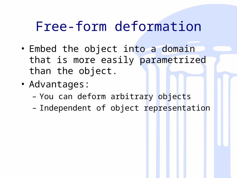
Free-form deformation
• Embed the object into a domain that is more easily parametrized than the object.
• Advantages: – You can deform arbitrary objects– Independent of object representation

Basics of m-reps
• Atom(‘hub’) position, x
• Spoke length, r• Spoke bisector, b• Object angle Ө• b, b┴ and n form local
coordinate frame
• Left, internal atom• Right, end atom

Object representation
• Mesh of medial atoms• Here, the middle one is internal, the rest are
end atoms

Discrete vs Continuous

Properties of m-reps
• The medial locus of an object is represented explicitly.
• A fuzzy approximate representation of the object's boundary is implied by the medial locus representation.
• An accurate description of the boundary is given by a smooth fine-scale deformation of the fuzzy implied boundary.

M-rep based deformation
• Mostly used for image segmentation
• Can be used for PBS as well
Initial model(ex: from an atlas)
Target imageDeformation
M-rep FEM modelFEM-based deformation
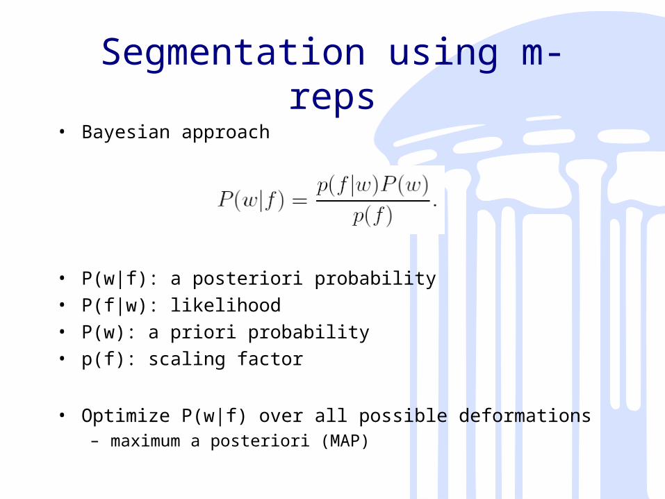
Segmentation using m-reps• Bayesian approach
• P(w|f): a posteriori probability• P(f|w): likelihood• P(w): a priori probability• p(f): scaling factor
• Optimize P(w|f) over all possible deformations– maximum a posteriori (MAP)

Algorithm
• Start with an initial model m
• Optimize F(m|Itarget)– F is a sum of two terms, log prior, and log
likelihood
• Can be applied at different scales• The initial model can come from
– Geometrical analysis of a set of hand-segmented training images
– A single hand-segmented training image

Algorithm details
• Manually place the model in the 3D image,
• Find and apply the similarity transform which optimizes F(m|Itarget)
• Until convergence, do – For each medial atom in m
• {Transform the atom to optimize F(m|Itarget)}
• For each boundary tile implied by m – {Shift the position of the tile along the tile’s
normal to optimize F(m|Itarget)}

Results
• Video

Advantages of m-rep based deformations
• Capability for deformation of the interior• Provides a way for appropriate locality based on
medical relevance• Multiple scale levels (multi-object, object, object
section, boundary)• Correspondences are preserved
Interactive Skeleton-Driven Dynamic Deformations
Steve Capell, Seth Green, Brial Curless, Tom Duchamp, Zoran
Popovic

What is this paper all about?
• Character animation• We want to tell how the character
should act• But we don’t want to tell how the
character should move!• The answer: elastically deformable
characters modeled with a simple skeleton

Application Areas
• Movies: You want to let the animator construct the model easily– Previous work included muscle, skin, etc
models – painful process
• Games, VR: You want to have interactive rates– Previous work included purely kinematic
deformations – not realistic
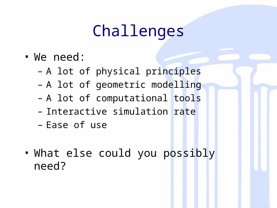
Challenges
• We need:– A lot of physical principles– A lot of geometric modelling– A lot of computational tools– Interactive simulation rate– Ease of use
• What else could you possibly need?

Skeleton and control lattice
• Each object Ω has:– A skeleton, S (in red)– A control lattice, K (in black)
• The control lattice can have hierarchical scale– K0 (in black) vs K1 (in green)

General Ideas
• Coarse volumetric control lattice provides the elements for FEM
• Motion control: Put line constraints along “bones” of the skeleton
• Form regions around bones, and simulate linearly in regions
• Hierarchical control lattice: Level-of-detail simulation

One simulation step• For each region do
– Extract regional variables from global system– Compute displacement from “rest state”
transformed according to the transformation of the “bone”
– Build the linear system for solving local equations of motion
– Solve the linear system using conjugate gradients
• Merge solution from each region, weighted (user-assigned weights)
• Update the global system state
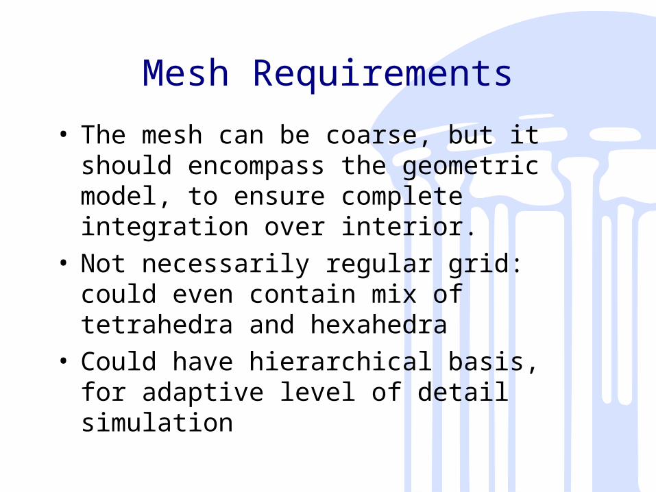
Mesh Requirements
• The mesh can be coarse, but it should encompass the geometric model, to ensure complete integration over interior.
• Not necessarily regular grid: could even contain mix of tetrahedra and hexahedra
• Could have hierarchical basis, for adaptive level of detail simulation

Ideas to achieve our goals
• Motion control via skeleton: add line (“bone”) constraints to the finite element model
• Make computation simpler: Have an edge in the mesh for each bone
• Interactive rate: Linearly solve motion equations around each bone, blending deformation at overlapping regions
• Similar approach to free form deformations, but here principles of continuum elasticity are used

Components
• The object (or the character): Domain Ω• The skeleton: a graph S, is a subset of Ω• Joints: Vertices of S• Bones: Edges of S• Motion: p(x, t)• Restriction Map: a piecewise linear function on
S, ps(x, t)

Goal
• Solve for the dynamic motion of the object given the motion of the skeleton
• Basically a PDE system with constraint:p(x, t) = ps(x, t) for all xєS
• Separate p(x, t) into a rest state r(x) and a displacement d(x, t)

The Hierarchical Basis• Control lattice: “Lazy
wavelets”
• For all i, j, i≠j, the intersection Ci,j = Ci U Cj is either empty or a face, edge, or vertex of both Ci and Cj.
• The edges of S are edges of cells of K.
• The domain is contained in the interior of K.
• For all i, each vertex of Ci has valence 3 (within Ci).

Equations of Motion• Kinetic energy T ( similar to ½mv2)
• Elastic potential energy V• Both T and V depend on q, q’• Euler-Lagrange equations

Computing V
• Strain tensor: degree of metric distortion– Green’s strain tensor
• Stress tensor: forces acting on the interior of a continuum– Shear modulus, G– Poisson’s ratio,
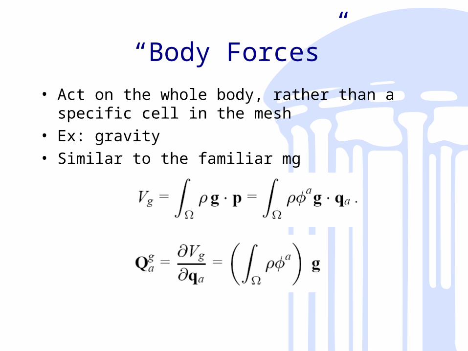
“Body Forces”
• Act on the whole body, rather than a specific cell in the mesh
• Ex: gravity• Similar to the familiar mg

Numerical integration
• Simple trick for speed up: precompute the integrals– Subdivide K– Compute basis functions at each vertex– Tetrahedralize– Compute integrals over each tetrahedron
using piecewise linear approximations
• Then use nonlinear Newton-Raphson to solve the system

Skeletal Simulation
• Did you actually believe they did all those expensive computations at interactive rate?– Of course not!
• First animate the skeleton (real quick)• Then approximate nonlinear dynamics

Regions
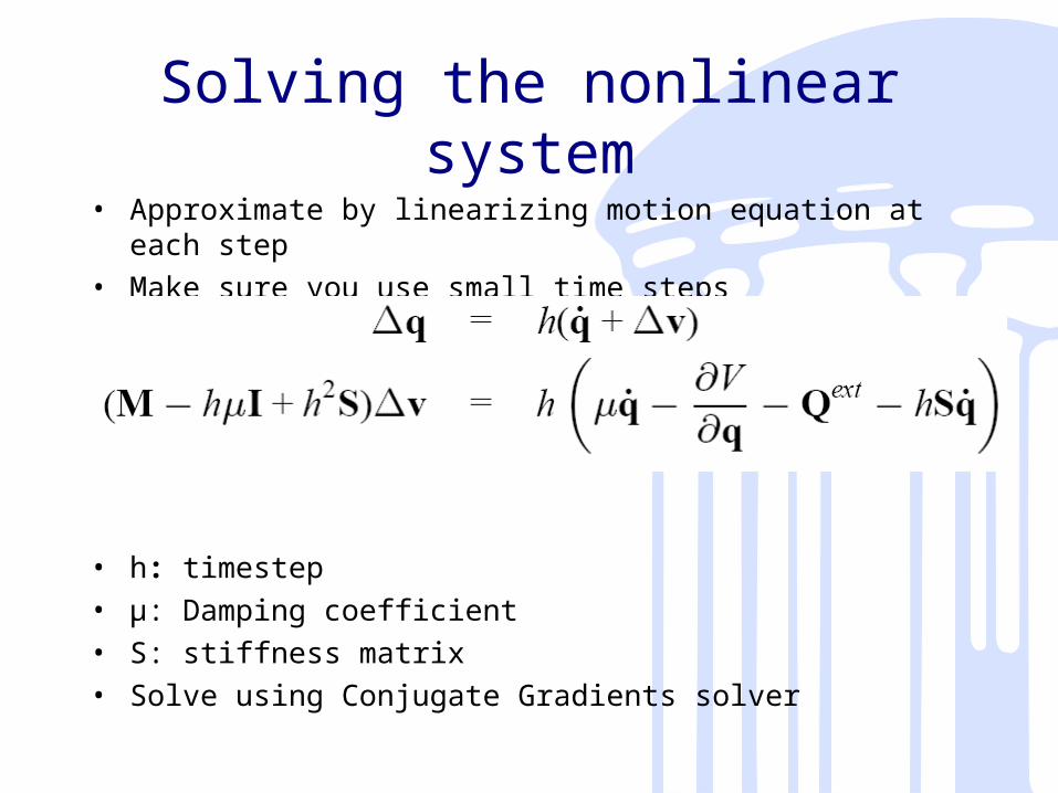
Solving the nonlinear system• Approximate by linearizing motion equation at each step• Make sure you use small time steps
• h: timestep• μ: Damping coefficient • S: stiffness matrix• Solve using Conjugate Gradients solver

Conjugent Gradient Method
• Initialize at P[0];• g[0] = h[0] := F(P[0]);• for i = 0 to n-1
– P[i+1] := minimum of F along the line h[i] through P[i], i.e., choose λ[i] to minimize
F(P[i+1])=F(P[i]+ λ[i] h[i]);– g [i+1] := F(P[i+1]);– γ [i+1] := (g[i+1]- g [i]) g [i+1] / g [i] g
[i];– h [i+1]:= g[i+1]+ γ [i] h[i];

Bone Constraints
• Skeleton is directly controlled by keyframe data• Requiring the bones to be on edges of S makes
things very simple• A control point on an edge a component of
∆v that is known a priori – ∆vk – known components– ∆vu – unknown components

Linear Subspace Constraints• What if we have more than one object?
– Position constraints- Extension of bone constraints
• RHS is constant a, for each timestep
• C =

Blended Local Linearization
• Problem: computation of the stiffness matrix at each time step– Soln: Linearize the strain tensor
• Problem: Severe distortions when deformation is large
– Better soln: Locally linearize• Idea: no large deformation from nearby bones• User-specified regions• Blend at places where regions overlap
– Define a binary Q matrix, where Q[a][b]=1 means that the basis function a is nonzero for the region b

One Simulation Step - revisited
For each region i do– Extract regional variables from global system
[ri, qi, q’i] = [Qi r,Qi q, Q’i q]– qi corresponds to displacement from rest state
transformed according to the transformation of the bone
For each a doqi
a = qia – Ti (ri
a) + ria
– Build the linear system for solving local equations of motion
Construct Ai and bi from bone constraint– Solve the linear system using conjugate gradients
Solve Ai ∆vi = bi
• Merge solution from each region, weighted
∆v =∑i Wi QiT ∆vi
• Update the global system state
q’ = q’ + ∆vq = q + hq’

Twist Constraint• We don’t twist much around our bones• Soln: soft constraint to penalize all displacement
near bones
• Quadratic its Hessian is constant
• Add to the stiffness matrix

Adaptation
• More details at places where large deformations occur
• Little deformation go up one level• Large deformation go down one level• Precompute and store related info
Contributions
• Crafting the function space to handle constraints
• Blended local linearization of non-linear equations
• Method of solving constraints using linear subspace projection
• New constraint for allowing 1D bones to behave like 3D

...contributions
• None of these are terribly novel, in fact
• But this is the first time so many techniques have been put together
• Result: interactive animation of arbitrary shaped characters with user control over skeleton

Results
• Show video

References• Interactive skeleton-driven dynamic deformations Steve Capell, Seth Green,
Brian Curless, Tom Duchamp, Zoran Popović July 2002 ACM Transactions on Graphics (TOG) , Proceedings of the 29th annual conference on Computer graphics and interactive techniques,
• Collisions and deformations: A multiresolution framework for dynamic deformations Steve Capell, Seth Green, Brian Curless, Tom Duchamp, Zoran Popović July 2002 Proceedings of the 2002 ACM SIGGRAPH/Eurographics symposium on Computer animation
• S.M. Pizer, T. Fletcher, Y. Fridman, D.S. Fritsch, A.G. Gash, J.M. Glotzer, S. Joshi, A. Thall, G Tracton, P. Yushkevich, and E.L. Chaney, "Deformable M-Reps for 3D Medical Image Segmentation," International Journal of Computer Vision - Special UNC-MIDAG issue, (O Faugeras, K Ikeuchi, and J Ponce, eds.), vol. 55, no. 2, pp. 85-106, Kluwer Academic, November-December 2003.
• PT Fletcher, SM Pizer, G Gash, and S Joshi, "Deformable M-rep segmentation of object complexes," in IEEE International Symposium on Biomedical Imaging (ISBI), pp. 26-29, 2002.
• Pizer S, S Joshi, PT Fletcher, M Styner, G Tracton, and Z Chen, "Segmentation of Single-Figure Objects by Deformable M-reps," in Medical Image Computing and Computer-Assisted Intervention (MICCAI), (WJ Niessen and MA Viergever, eds.), (New York), pp. 862-871, Oct. 2001.
• Yushkevich, Paul (2003). Statistical Shape Characterization Using the Medial Representation. PhD dissertation. Advisor: Prof. Stephen Pizer