deliverable 3 – es manager architecture and global
TRANSCRIPT

EFACEC public information
FLEXERGY
Deliverable 3 – ES Manager architecture and global specification
Activity 1:
Preliminary Studies
Editor: Marta Ribeiro
Dissemination level: (Confidentiality)
Public
Suggested readers:
Version: 01.02
Total number of pages: 37
Keywords: Energy Storage, System Architecture, Energy Management
FLEXERGY is a project co-funded by:
FLEXERGY ABSTRACT
The FLEXERGY project aims at the development of an advanced management solution, highly innovative and provided of artificial intelligence, for the management of assets of battery energy storage systems, integrated with renewable energy sources or for application within a microgrid
Deliverable 3 – ES Manager architecture and global specification, Doc No.: AS19007925, Rev. 1.02 Page 2/37
Document
Language Requirements (for non-native English speakers)
In order to fully understand the content of this document, it is therefore recommended that the reader possesses a language proficiency equivalent to B1 level, according to European Language Levels
Disclosure
This document contains information, which is confidential in nature and proprietary to EFACEC, Automation Business Unit, and shall not be reproduced or transferred to other documents or referenced, or disclosed in any manner to any person or used for any purpose other than that for which it is furnished without the prior express written permission of EFACEC
Name Deliverable 3 – ES Manager architecture and global specification
Document No. AS19007925
Revision and Date 1.02 2019-05-31
Project FLEXERGY
Made by Marta Ribeiro
Reviewed by Luís Azevedo Costa
Approved by Alberto Bernardo
Total Pages 37

Deliverable 3 – ES Manager architecture and global specification, Doc No.: AS19007925, Rev. 1.02 Page 3/37
Revisions
Rev. Date Comments Author
1.0 2018-03-10 Document release Ismael Miranda
1.01 2019-02-22 First draft Marta Ribeiro
1.02 2019-05-31 Minor changes Marta Ribeiro

Deliverable 3 – ES Manager architecture and global specification, Doc No.: AS19007925, Rev. 1.02 Page 4/37
Executive Summary
The FLEXERGY project is promoted by Efacec’s Automation unit which growing strategy is based on keeping the forefront of
technological. FLEXERGY is a research and technological development project to be developed in order to achieve the growth
and strength of energy storage solutions.
The aim of the project is the development of an advanced management solution, highly innovative and provided of artificial intelligence, for the management of assets of battery energy storage systems, integrated with renewable energy sources or for application within a microgrid.
This document presents the requirements specification and the high level architecture of the new solution for ES Manager. For
this purpose, the specification team has identified both functional and non-functional requirements on a high-level basis.

Deliverable 3 – ES Manager architecture and global specification, Doc No.: AS19007925, Rev. 1.02 Page 5/37
Table of Contents
EXECUTIVE SUMMARY ............................................................................................................ 4
GLOSSARY ......................................................................................................................... 7
1. ENERGY STORAGE MANAGER: HIERARCHY AND FUNCTIONALITIES................................................ 8
1.1 FUNCTIONAL DESCRIPTION OF SYSTEM OBJECTIVES .......................................................................................... 8 1.1.1 Real Time Display of System Status and Alarms ............................................................................................9 1.1.2 Activation and Manipulation of Energy Functions ..........................................................................................9 1.1.3 System Values Logging and Statistics ........................................................................................................9 1.1.4 Collaboration with External Actors ..........................................................................................................9 1.1.5 Management and Optimization Functions ................................................................................................. 10 1.1.6 Dashboard ..................................................................................................................................... 10
2. ES MANAGER HIGH LEVEL ARCHITECTURE ........................................................................... 10
2.1.1 System Overview ............................................................................................................................. 10 2.2 MODULES DESCRIPTION .................................................................................................................. 11
2.2.1 Graphical User Interface Module ........................................................................................................... 11 2.2.2 External Data Interface Module ............................................................................................................ 12 2.2.3 Weather Forecast Module ................................................................................................................... 12 2.2.4 PV and Wind Forecast Modules ............................................................................................................. 12 2.2.5 Load Forecast Module ....................................................................................................................... 12 2.2.6 AMI Module .................................................................................................................................... 12 2.2.7 Operation Management Module ............................................................................................................ 12 2.2.8 Optimal & Planning Module ................................................................................................................. 12 2.2.9 Data Analysis and KPIs calculation Module ................................................................................................ 13 2.2.10 Database ...................................................................................................................................... 13 2.2.11 ES Controller .................................................................................................................................. 13 2.2.12 EV Charging Manager ........................................................................................................................ 13 2.2.13 RES Controller ................................................................................................................................ 13 2.2.14 Load Controller ............................................................................................................................... 13 2.2.15 Genset Controller ............................................................................................................................ 13
3. TECHNICAL DESCRIPTION ............................................................................................... 14
3.1 SOFTWARE PLATFORM ................................................................................................................... 14 3.2 TECHNOLOGIES .......................................................................................................................... 14
3.2.1 Programming Languages ..................................................................................................................... 14 3.2.2 Protocols ...................................................................................................................................... 14 3.2.3 Database ...................................................................................................................................... 14 3.2.4 Security ........................................................................................................................................ 14
APPENDIX A - FUNCTIONAL REQUIREMENTS: SYSTEM FEATURES ...................................................... 16
1. USERS MANAGEMENT .................................................................................................................... 16 2. ASSET AND INFRASTRUCTURE MODELLING ................................................................................................. 18 3. ENERGY FUNCTIONS ..................................................................................................................... 21 4. COMMUNICATIONS ....................................................................................................................... 30 5. INFRASTRUCTURE MANAGEMENT .......................................................................................................... 31 6. OPERATION MANAGEMENT ............................................................................................................... 34 7. SYSTEM MANAGEMENT ................................................................................................................... 34
APPENDIX B - NON-FUNCTIONAL REQUIREMENTS......................................................................... 36
1. SYSTEM AVAILABILITY .................................................................................................................... 36 2. SYSTEM SECURITY ....................................................................................................................... 36

Deliverable 3 – ES Manager architecture and global specification, Doc No.: AS19007925, Rev. 1.02 Page 6/37
List of Figures
Figure 1.1 - Interactions between use cases. ................................................................................. 8
Figure 2.1 - Graphical representation of the ES Manager layered software architecture. ........................... 11

Deliverable 3 – ES Manager architecture and global specification, Doc No.: AS19007925, Rev. 1.02 Page 7/37
Glossary
AMI Advanced Metering Infrastructure
AMI Advanced Metering Infrastructure
API Application Programming Interface
BESS Battery Energy Storage System
CAPEX Capital Expenditure
CEP Complex Event Processing
DER Distributed Energy Resource
DR Demand Response
ESC Energy Storage Controller
ESCO Energy Service Company
ESM Energy Storage Manager
ESS Energy Storage System
EV Electric Vehicle
IED Intelligent Electronic Device
KPI Key Performance Indicator
LCA Life Cycle Assessment
OPEX Operational Expenditure
PCC Point of Common Coupling
PV Photovoltaic
RES Renewable Energy Source
SCADA Supervisory Control and Data Acquisition
SoC State of Charge
SoH State of Health
TSO Transmission System Operator

Deliverable 3 – ES Manager architecture and global specification, Doc No.: AS19007925, Rev. 1.02 Page 8/37
1. Energy Storage Manager: Hierarchy and Functionalities
The FLEXERGY project aims at developing an advanced and highly innovative management solution, enabled by artificial intelligence, suitable for managing battery-based energy storage assets, integrated with renewable energy sources or meant to be applied in microgrids. This platform will be developed according to the intrinsic features of this kind of systems, being suitable for adaptation to different scopes of integration.
The Energy Storage Manager (ES Manager/ESM) is a critical system component of the FLEXERGY project, hierarchically located between the Energy Storage Controller (ES Controller / ESC) and its various field equipment, including batteries, inverters, switches, cooling system and auxiliary equipment, and the equipment and interfaces used by higher level, objective-oriented actors: the terminals used by facility and system operators to monitor and maintain secure operations in various grid configurations; the external energy market and weather forecast information, among others, that allow the proprietors and stakeholders to optimize the economic integration of renewable energy production and electric vehicle charging stations; and the analysis tools used to maximize the useful life of critical equipment, namely the batteries themselves, while they perform these services to their neighbouring systems.
The ES Manager is capable of managing several ES Controllers, RES Controllers, EV Charging Managers, Genset Controllers and Load Controllers, in a scalable concept and is able to incorporate the existing relationships and configurations between the various assets of the electrical grid. Since ES Manager is a management and optimization platform, this platform performs dynamic optimizations in order to mitigate forecasting errors and respond to unforeseen scenarios.
As per the FLEXERGY Use Cases documentation, discussion of choices and aptitude of tools and architectures follows the 5 following target use cases:
• Use Case 1: Technical and economic optimization of hybrid park (PV/ Wind/ Storage) supported by battery energy storage system
• Use Case 2: Battery Energy Storage System as a buffer for Electric Vehicles (EVs) integration
• Use Case 3: Holistic optimization of microgrids integrating energy storage
• Use Case 4: Maximizing distributed storage net profit through the provision of multiple services
• Use Case 5: Maximization of batteries useful time through Life Cycle Assessment (LCA)
Figure 1.1 - Interactions between use cases.
1.1 Functional Description of System Objectives
As a managing system, ES Manager is projected with a variety of functions and interfaces, both oriented towards humans (HMI) and machines (MMI). To narrow the scope of projected functions, the five main use cases projected for the system are presented here. The ES Manager will be able to perform multiple functionalities simultaneously through the development of advanced management algorithms that allow the management of the energy storage capacity combined with the management of common DER assets and controllable loads. In Attachments A and B, there is a more detailed description of the functional requirements, features and major services that the system shall fulfill.

Deliverable 3 – ES Manager architecture and global specification, Doc No.: AS19007925, Rev. 1.02 Page 9/37
1.1.1 Real Time Display of System Status and Alarms
A BESS is composed of valuable equipment functioning in highly dynamic scenarios and under potentially high stress; as such, maintenance, current status and error notification are major necessities to guarantee the good and long-lasting functioning of the system.
Real time display of system status and alarms is a target function to the following use cases:
• Use Cases 1, 2, 3 and 4: Monitoring of system status is essential to predict and prevent errors that may decrease or completely disrupt availability of the service, resulting in economic losses and, depending on the severity, incurring penalties for the breach of responsibility to maintain the stability of the network on the system’s end. Considering that an adjacent EV charging station or the microgrid control and protection equipment can be seen as a service of the storage system, steady operation of storage translates to a steady operation of these services. Additionally, integration with ES Manager allows not only similar monitoring and control over the services themselves but facilitates it over the whole service chain.
• Use Case 5: Careful monitoring of operational efficiency and the self-evaluation of equipment health optimizes the useful life of equipment by way of fault identification and location and evaluation of the results of the weighted scheduling against projections of unaltered scheduling.
1.1.2 Activation and Manipulation of Energy Functions
The added-value functions of the BESS, mainly depicted in use cases 1, 2, 3 and 4, are its main purpose, and as such their timely and correct activation and management is of utmost importance. These functions are of varying complexity and are often simultaneous, coordinating battery charging and discharging with support functions designed to maximize balancing and non-disruptive interface with both the low and medium voltage grids. It becomes imperative to make the activation and scheduling of such functions both secure and flexible, allowing for on-demand response to external variables such as market shifts without sacrificing security. Such commands are also filtered by automatic systems to predict and prevent errors, either human in origin or algorithmic, based on incomplete data.
All of the considered use cases are made operational by the activation and manipulation of the base control functions implemented in the Assets Controllers. It is the ES Manager’s responsibility to translate the adequate responses engineered in the to fulfil the service needs of use cases 1 through 4, while maintaining the system’s overall health and security needs of use case 5, into the correct combination and scheduling of equipment-oriented commands and delivering them to the ES Controller.
1.1.3 System Values Logging and Statistics
All aspects of the BESS require some sort of data collection and storage. Maintenance technicians use alarms and status to predict and identify faults; efficiency ratings of the equipment are important inputs for the various economic optimization methods that support the system’s control; analysis of the system’s efficiency and impact are required to measure KPIs and evaluate the system.
To this end, a thorough and detailed storage of system statistics, operational values and issued commands is essential for the managing of the BESS:
• The service-oriented use cases 1, 2, 3 and 4 benefit from the tracking of all aspects of their usage: magnitude, frequency of requests, duration of requests and efficiency, among others, are essential for tracking the performance of the services, their availability and, ultimately, their economic viability.
• This data supports use case 4 in predicting the most appropriated way to accomplish multiple services, compliant with the grid conditions, with renewable generation fluctuation and with the own BESS conditions.
• Statistics management is paramount to the maintenance of the useful life of the batteries, since it allows technicians to monitor complex characteristics that are only visible in the long term, such as degradation of the batteries’ maximum capacity, power and efficiency, and plan accordingly to minimize costs and downtime.
1.1.4 Collaboration with External Actors
The dynamics of the battery storage system require real time information on a number of different fields, ranging from weather predictions to market prices, with grid performance and requirements in between. The assistance of external actors, who can feed this information to the system, allows it to remain focused on the control and monitoring aspects.
• Use Case 1 and its proposal of renewable energy integration are the flagship case for the functional requirement of external actor. By using weather data from an external actor to predict periods of peak wind and solar production, along with data from the energy market, the system can make the informed decision to generate directly to the grid during the periods of peak load and to store the generated energy during off-peak periods, thereby incurring a greater financial gain and helping stabilize the production to conform to the load of the grid.
• Other use cases can also benefit from external actors. For example, use case 2 can make use of an off-system platform

Deliverable 3 – ES Manager architecture and global specification, Doc No.: AS19007925, Rev. 1.02 Page 10/37
for the queueing services, most notably in the case of a public EV charging station; and a data sharing platform for ES Manager can share the crucial information for use case 5’s optimization of system health between battery systems with similar component choices.
1.1.5 Management and Optimization Functions
The FLEXERGY project aims at developing an advanced and highly innovative management solution, enabled by artificial intelligence, suitable for managing battery-based energy storage assets, integrated with renewable energy sources or meant to be applied in micro grids. Then, this platform, the ES Manager, incorporates optimization algorithms that are activated according to the designated use case. These optimization blocks follow predefined objectives for each use case. The objectives are as follows:
• Use Case 1: optimization of the management of the charge and discharge cycles of the BESS in the presence of RES, increase of the predictability and controllability of the energy renewable resource, maximize the economic performance of the hybrid park, fast response to grid limitations or constraints;
• Use Case 2: maximize the economic performance of the system, reduction of power peaks, minimize the risks of power outage;
• Use Case 3: minimization of the energy costs for the system, maximization of self-consumption with maximization of the penetration of RES, continuity of service improvement, reduction of power peaks, reliability of microgrid;
• Use Case 4: maximization of the revenue of the system, provision of multiple services, higher accommodation of RES, reduction of grid congestion;
• Use Case 5: maximization of the useful lifetime of the batteries considering controllable variables and increase the global efficiency of the system.
1.1.6 Dashboard
A system dashboard allows the stakeholder and/or the proprietor of the facility to easily track the performance of the system. Multiplying the numerous components of this system by their several important KPIs easily reveals the massive number of indicators to follow and, in that vein, the importance of a well organized and updated dashboard.
• Use Cases 1 and 2, as service-oriented and with a clearly economic objective, are prime use cases for a system dashboard that displays economic KPIs such as revenue and technical KPIs such as reduced energy curtailment of RES and the smoothing performance.
• Use Case 3 and 4 is an important support case to the service provider cases, and its performance as measured in microgrid generation reliability and peak shaving are essential to evaluate the performance of these functions.
• Use Case 5 translates into a more efficient use of equipment, and its performance as measured in system global efficiency and number of cycles to failure.
2. ES Manager High Level Architecture
2.1.1 System Overview
The chosen architecture for ES Manager is a four-layer architecture, not dissimilar from typical smart grid architectures but adapted to the specific needs of the system. A graphical representation of these layers is presented in Figure 2.1.

Deliverable 3 – ES Manager architecture and global specification, Doc No.: AS19007925, Rev. 1.02 Page 11/37
Figure 2.1 - Graphical representation of the ES Manager layered software architecture.
The Field layer consists of interfaces with ES Controller and other low-level field equipment such as EV charging stations, renewable generation sources, controllable loads, conventional generation, and auxiliary industrial equipment. These are often characterized by limited purpose equipment that interfaces using typically industrial communication protocols, such as ModBus, IEC 61850, IEC 60870-5-104 and OCPP, among others. While not all of these have uncommon requirements related to their physical interfaces – rather than functioning over TCP/IP, for example, - many, if not all, of these protocols have particularities when it comes to frame format, periodicity, data types and role selection, to name a few.
The WAN layer allows ES Manager to not be required to be at the same level as the controllers. The protocol used for communication is TCP/IP which allows long distance communication rapidly and without loss of information.
The Backend/Fronted Systems layer includes the algorithms that directly affect economic maximization, energy efficiency, and the optimization of the lifespan of the various system components. These predictions make use of information that originates both inside the system, either from the field equipment or the configurable user settings, and outside the system, usually through API interfaces with partnered systems. Through the Operation Management Module, all the modules have the connection to one database, to which they store operational data, or use said data for statistics and algorithms. This layer contains a human-machine interface oriented towards presenting system values and alarms, editable device configuration and usage statistics based on operation data and system configuration. It also encompasses the operational dashboard, where a user can accompany the evolution of the system’s economic and operational performance. It should be usable by all human actors in the system’s use cases, locally and remotely, from managers to maintenance technicians.
The external layer consists of the interface between various services that provide all the information required for the optimization and management modules. This layer has the ability to provide the data whenever ES Manager determines it.
2.2 Modules Description
2.2.1 Graphical User Interface Module
To display the real time system data – operational, statistic and alarm synoptics –, the system requires a flexible and customizable way to present real time system data. Operators and maintenance technicians also require the control options to alter or completely stop system processes in the case of an emergency or scheduled stop. To this end, a browser based solution, making use of the Web Services component, provides a means of display that is flexible not only in terms of design, utilizing the customization power of the traditional web development tools of HTML, CSS and JavaScript, but in terms of providing a display to desktop and mobile devices without the need for two extensively different remote terminal applications.

Deliverable 3 – ES Manager architecture and global specification, Doc No.: AS19007925, Rev. 1.02 Page 12/37
2.2.2 External Data Interface Module
Used to receive external data regarding market information, being used to interconnect with other entities such as energy retailers and energy services companies.
2.2.3 Weather Forecast Module
Responsible for acquiring the weather forecasts from an external meteorological service and for processing the data (e.g. replacing missing values and changing the timestep) of the same forecasts.
2.2.4 PV and Wind Forecast Modules
Performs the forecast of energy production through photovoltaic panels or through wind turbines for a given time horizon. These modules contain different Machine Learning algorithms in order to obtain reliable results and for the flexibility of the modules. For this purpose, these modules receive historical and current weather forecast data and historical generation data from the respective renewable source.
2.2.5 Load Forecast Module
Performs the forecast of energy consumed by the different types of loads present in the micro-grid: non-controllable loads, controllable loads and electric vehicles. Like the generation forecast modules, this module incorporates a Machine Learning algorithm in order to obtain reliable forecasts. For this purpose, this module receives a historical time-series consumption for each type of load.
2.2.6 AMI Module
Responsible for all the tasks that involve the treatment of the data received from the field.
Works as the gateway between the field and the system comprising all the algorithms used to manage the raw data and extract relevant features for supporting the management and optimization modules. It handles the large amounts of data resulting from the IEDs, smart meters and other measurement sensors, with communication capabilities, connected to the ES Manager.
It performs among others the verification of the consistency of data by identifying outliers (erroneous measurements), performing data imputation (replacing missing values) and selecting the most observable period, so that the operation of the other modules is not jeopardized.
2.2.7 Operation Management Module
Coordinates the execution of all the other modules.
It is responsible for the autonomous triggering of all the tasks according to the use case selected (e.g. invoke optimizations). Validates if the current operation is according to the planned. If not, will request the Optimal & Planning Module new operation plan to cope with the discrepancies observed.
Thus, this module has two operating modes:
1. Normal state profile management - This mode merely coordinates the execution of all the modules according to the proper operation of the selected use case.
2. System contingency response management - This mode contains the information of all assets and applies contingency measures in case of loss of any asset, manages events and alarms that may come from the field. The preventive maintenances are also scheduled through this mode and prepares the network for these same maintenances.
2.2.8 Optimal & Planning Module
Depending on the use case selected by the operator, the corresponding optimization blocks are called for the same use case. The optimization blocks contain algorithms that meet the objectives of each use case. The optimization blocks are as follows:
• Minimization of deviation cost from a give profile – maximization of the economic performance of the hybrid park (UC1) or the Microgrid (UC2, UC3)
• Maximization of net profit through energy arbitrage in a market pricing scheme – maximization of the economic performance of the Microgrid (UC2, UC3) in a market pricing scheme
• Minimization of operation costs - holistic optimization of a microgrid integrating energy storage and DERs (UC2, UC3)
• Battery Useful Life Maximization – optimization of some controllable parameters associated to the batteries SoH (UC5)
• Multiple Services Optimization - operation strategy optimization for the performance of multiple services, implementing an optimized allocation of battery capacity for different purposes of the electric sector (UC4)

Deliverable 3 – ES Manager architecture and global specification, Doc No.: AS19007925, Rev. 1.02 Page 13/37
2.2.9 Data Analysis and KPIs calculation Module
Data analysis is an important feature of this system, being essential to many of the added value functionality of the operation. Analysis of operational data extracts efficiency of the system, availability of resources, general response times, functional limits of the equipment and evolution of system health.
Also, in this module it is performed the technical and economic performance evaluation of the system, performing a post-analysis, based on several identified KPIs for each use case. The results obtained are then presented on a dashboard using the Graphical User Interface Module. The user can define the period for the calculation of the KPIs.
2.2.10 Database
The database component has a critical function in the system, and its integration with all of the remaining components is of foremost priority. As the data storage of operational data gathered by the AMI module, it feeds the modules in their optimization, forecast and profile generation duties; the results are then displayed in the Graphical User Interface Module for technical control and economic and longevity KPI evaluation. It should be robust and secure, but with a simple interface that can be easily accessed by each other component.
2.2.11 ES Controller
ES Controller is the main controller of the field equipment, responsible for the coordination of the energy, protection and cooling equipment. It executes simplified functions, such as charging or discharging batteries or balancing the microgrid with the rest of the grid. However, activating these functions requires inputs that may be the result of a complex economic or efficiency maximization algorithm that functions in the higher levels of the system.
These inputs must be transmitted to ES Controller, which in turn will coordinate the equipment to that end. As an industrial PLC, ES Controller may be equipped with typically industrial protocols such as ModBus, IEC 60870-5-104 or IEC 61850, and ES Manager solution must be equipped with at least one such protocol. The software component responsible for interfacing with ES Controller is also responsible for the logging of system values into the database and transportation of real-time status data to the human-machine interface components.
2.2.12 EV Charging Manager
As per Use Case 2, FLEXERGY previews the inclusion of electric vehicle charging stations in the microgrid that is to be controlled by ES Manager. Like typical analogue industrial equipment, control of such a station is performed through a proprietary or open-sourced standard protocol designed for the effect. The Open Charge Point Protocol (OCPP) is the predominant choice in the European market, as an open-source option for electrical vehicle charge station control, and as such ES Manager must be able to communicate in this protocol. Components responsible for charge station management must also have write access to the database for data storage, which feed the data analysis and by extension the dashboard components.
2.2.13 RES Controller
Relating to Use Case 1 in the case of renewable energy, and as a support to Use Case 3 in the case of microgrid integration, renewable and non-renewable generation fall into the category of equipment likely to be managed by ES Manager. Since other requirements of the architecture add to ES Manager the capability to communicate using many of the typical industrial protocols, e.g ModBus, IEC 60870-5-104, IEC 61850, these capabilities can also be used to provide auxiliary control and monitoring features to the system.
2.2.14 Load Controller
This type of controller is present mainly in Use Case 3. This controller receives setpoints from the ES Manager with the load consumption limits, taking into account the load priority. The load curtailment is executed by steps and the controllable loads are configured in terms of minimum time between curtailment events and maximum period of time that the load can remain curtailed. The communication between the ES Manager and the Load Controller is performed through the standard industrial protocols, e.g. ModBus, IEC 60870-5-104 and IEC 61850.
2.2.15 Genset Controller
Like the Load Controller, this controller is present mainly in Use Case 3. For optimization purposes, gensets are characterized as negative flexible loads, with negative curtailment and are thus controllable. The ES Manager is capable to control the minimum and maximum power deliverable by the generator when fully operational. Like the Load Controller, the communication between the ES Manager and the Load Controller is performed through the standard industrial protocols, e.g. ModBus, IEC 60870-5-104 and IEC 61850.

Deliverable 3 – ES Manager architecture and global specification, Doc No.: AS19007925, Rev. 1.02 Page 14/37
3. Technical Description
3.1 Software Platform
The core of the FLEXERGY software solution requires a high degree of flexibility, both due to the large number of equipment and other software components that must be integrated in the final solution, the associated intensity and frequency of communication between it and its adjacent components, and the ability to scale both in compatible protocols, implemented functions and number of associated providers and actuators.
As such, the chosen architecture for FLEXERGY is a service-oriented architecture where each service represents a set of logical business functions. For example, for services that are acquired from external sources (such as weather forecast), whether from our partners or other sources, the component is a webservice interface to and from which the external source can get requests and provide information.
3.2 Technologies
3.2.1 Programming Languages
The choice of programming language is conventional, by industry standards, for each of the components:
• The application server is Java-based, and as such each application is programmed using Java. This does not limit the choice of external providers.
• The Web Service component will be a REST server, providing both a web server for browser clients and the necessary webserver for external APIs.
• The Human-Machine Interface and Dashboard will be traditional web pages, powered by the web development tools HTML/CSS/JavaScript, and serviced by the Web Service component.
It should be noted that as the system evolves, and its necessary improvements are made clearer, the “trunk and branches” model made available by the application server shall easily adopt any new feature or function.
3.2.2 Protocols
Development of the ES Controller has revealed that operational commands to the ESC have to be sent through one of its industrial protocol communication channels: ModBus, IEC 60870-5-101/104 (IEC 104) or IEC 61850. For accessibility, familiarity and overlap with additional peripheral equipment, IEC 61850 was chosen as the protocol to interface with the ESC, with Java as the implementation tool.
The remaining protocols, along with other industry standards, are considered for the support of other peripheral industrial equipment that may be required. Their long-lasting presence in the industry and well-worn technology improves the availability of interface libraries, most typically on Java tools.
As for the specific case of EV charging stations, the target protocol – Open Charge Point Protocol – is based on the XLM, JSON and SOAP technologies. Being relatively high level technologies and widely used in web services and web-based communication indicates that there is low risk of incompatibility in the implementation of OCPP control in most programming languages.
3.2.3 Database
The database component of the ES Manager is foundational to the operation of the software. All components of the Equipment, Business and Presentation layer make extensive and frequent use of database operations: the first to log operational variables of the field equipment, and the latter to calculate generation profiles, estimate economic efficiency, optimize the useful life of the equipment and display all of this data and statuses to operators, technicians and shareholders. Using SQL databases fulfils this important requirement of wide compatibility between the system components, as it is a widely used technology and compatible with many programming tools. It also has continual updating and support, and is open sourced, meaning its internal security is guaranteed by the ability to review transparent code.
3.2.4 Security
The rise of cyberattacks is accompanied by the increased relevance of cybersecurity, and industry reports allow new players to determine ahead of time some of the dangers to be aware of. Denial of service and data theft are problematic situations in the best of cases, but system hijacks are potentially the worst type of attack that the ES Manager could be subjected to. With the power to manage large amounts of power electronics equipment, the danger potential to human life becomes a major threat along with the possibility of economic damage to the local microgrid and even the macrogrid.

Deliverable 3 – ES Manager architecture and global specification, Doc No.: AS19007925, Rev. 1.02 Page 15/37
Therefore, beyond the typical measure of database and file encryption – which effectively prevent data theft and its associated economic risks -, both terminal and network access to the ES Manager require extensive security measures, such as monitoring of connections, network segmentation, firewalls, role-based access to features and controls and reinforced access control.

Deliverable 3 – ES Manager architecture and global specification, Doc No.: AS19007925, Rev. 1.02 Page 16/37
Appendix A - Functional Requirements: System Features
This section comprises a thorough description of the functional requirements, features and major services that the system shall fulfil. The requirements are classified by priority, where P1 means high priority and P3 is low priority.
1. Users Management
Item Description
Ref. users.01
Description
The System shall provide role-based access based on user identity and user role. It shall have following types of users:
• Administrator
• Operator
• Field staff
• Viewer/Guest
Rationale
Present to the user only the right amount of information according to its role on the system. Prevent users to access confidential information or information that belongs to other users.
It shall also be considered the possibility to give access to visualization of some information but not change it. Example: limits for BESS, etc.
Priority P1
Requirements
Req1: The Administrator is the person or people who will have any and all the privileges of all other user types. They will be able to impersonate other employees within the system. They will also have access to all the information and web-pages available on the system. This user is mostly used during the system’s setup and configuration for clients. It is also used for adding new users (clients) to the system and respective configurations. This role has full privileges to all servers in the cluster. This role can create additional roles.
Req2: The operator/client is the person or people which will be using the system on a current basis being responsible for managing the micro-grid. It shall have permissions to add new users with the role of guest or field staff. It has access to the information related with the operation. It shall have only access during the period that is defined by the administrator (e.g. for trial version).
Req3: The field staff is the person or people which will be using the system to perform interventions on the field and validate those actions are correctly performed (e.g. adding energy storage system to the system). It shall have only access during a certain period of time that shall be defined by the operator or administrator.
Req4: The viewer/guest is the person or people which will only be using the system to visualize data. It shall have only access during a certain period of time that shall be defined either by the operator or administrator.

Deliverable 3 – ES Manager architecture and global specification, Doc No.: AS19007925, Rev. 1.02 Page 17/37
UML
Item Description
Ref. users.02
Description The system shall be designed over a software as a service architecture meaning it can consist of n replicated subsystems that are used by different users. Each subsystem represents an application that is available for specific users which can have different roles.
Rationale Use the same system to provide the same application to a multitude of different users, each user representing a different client/operator. This way it is possible to reduce the system’s OPEX and CAPEX.
Priority P2
Requirements
Req1: A user that belongs to a subsystem cannot have access to other subsystem data.
Req2: The data of each subsystem shall not be accessible from the other subsystems.
Req3: The system shall support as many subsystems as needed (only requiring dimensioning of the hardware).
Req4: The system administrator shall be capable to access and edit all the available subsystems that belong to him.
UML

Deliverable 3 – ES Manager architecture and global specification, Doc No.: AS19007925, Rev. 1.02 Page 18/37
Item Description
Ref. users.03
Description The system shall provide an audit log of the user activity on the system.
Rationale Enable operators to keep track on the user’s modifications introduced, information accessed, and other actions carried out for an enhanced operation.
Priority P3
Requirements
Req1: All users’ actions shall be logged and timestamped.
Req2: Data editions shall be logged and time-stamped along with the username, and modification reasons. The justification shall be selected from a pre-defined list maintained by system’s administrator.
Req3: All actions shall be logged in a user-level context. From this audit log, it must be possible to determine:
• Used/initiated functions, login attempts, user commands
• Configuration and parameter changes
• Information changes
• Manual actions (receipt of alarms etc.)
Req4: From the audit log shall be able to pinpoint a user and a timestamp for any relevant action in the system.
UML
2. Asset and Infrastructure modelling
Item Description
Ref. asset.01
Description The system shall have a detailed model for all the existing assets controlled by the ES Manager.
Rationale Use appropriated models to each kind of asset.
Priority P1

Deliverable 3 – ES Manager architecture and global specification, Doc No.: AS19007925, Rev. 1.02 Page 19/37
Requirements
Req1: The system shall have a detailed model for the following assets (each model shall be detailed during the software API specification):
• Smart Meters
• RES Controllers
• Energy Storage Controllers (ESC)
• Energy Storage Systems (ESS)
• Genset Controllers
• Data Concentrators
• IEDs (sensors, RTUs)
• EV Charging Managers
• Dispatchable and non-dispatchable loads
Req2: There shall be a hierarchical relation between an ESC and ESS. The ESS is managed by the ESC. An ESC can control more than one ESS.
Req3: There shall be a hierarchical relation between a RES Controller and PV/wind power panel. The PV/wind power panel is managed by the RES Controller. A RES Controller can control more than one PV/wind power panel.
Req4: There shall be a hierarchical relation between a Genset Controller and Genset. The Genset is managed by the Genset Controller. A Genset Controller can control more than one Genset.
Req5: There shall be a hierarchical relation between a Load Controller and Controllable Load. The Controllable Load is managed by the Load Controller. A Load Controller can control more than one Controllable Load.
UML
Item Description
Ref. asset.02
Description The system shall have a detailed model for different types of installations/systems. An installation consists of physical place, with a common Point of Connection to the public grid and that has one or more functions and has inside one or more assets from the feature infra.01.
Rationale Use appropriated models to each system assets.
Priority P1
Requirements
Req1: The grid is a concept that represents a way of aggregating all the assets that belong to a certain user or group of users and has a specific location. Each user may have more than one grid. A grid can have the following types: i) microgrid; ii) prosumer and iii) power plant. It shall also be pointed out that the grid shall also contain all information regarding network infrastructures that is used to connect all assets.
Req2: Each of the installations above shall have an IED (meter or sensor), which is responsible for measuring the energy exchanged with the grid. Check feature infra.01.
UML

Deliverable 3 – ES Manager architecture and global specification, Doc No.: AS19007925, Rev. 1.02 Page 20/37
Item Description
Ref. asset.03
Description The system is capable of managing the system assets on autonomous fashion.
Rationale Simplify and automate processes. By enabling self-discovery features users may focus on operation process. Additionally, it will reduce effort on the implementation of AMI, reducing costs.
Priority P2
Requirements
Req1: the system is capable of automatically recognizing all the communicating devices that are installed on the field and are configured to exchange information with the ES Manager. It has the following features:
• Centralized management GPRS/UMTS/LTE/IoT/RF networks
• Network provisioning
• Performance monitoring
• Trouble shooting
UML
Item Description
Ref. asset.04
Description The system shall be capable of storing historical data in the platform database.
Rationale The ES Manager shall be capable of storing historical operation profile data for each controlled asset in the platform database, making it available for future analysis.
Priority P1
Requirements
Req1: The system shall be capable of saving information, such as the data of consumption/ generation of the different assets on the field, forecast information and the output of the optimization algorithms.
Req2: The system shall have a routine for requesting historical information according to a configurable periodicity.
Req3: The granularity of the information shall be configurable by data entity, only limited by the installed drive capacity. Additionally, for storage optimizations purposes, both cyclic and jitter procedures shall be configurable per data entity.
Req4: The horizon of the historical information shall be configurable.
Req5: The historical information shall be possible to consult in runtime, upon a filter for data type and time period. It shall also be possible to extract to *csv for analysis in third-party SW tools.
UML

Deliverable 3 – ES Manager architecture and global specification, Doc No.: AS19007925, Rev. 1.02 Page 21/37
3. Energy Functions
Item Description
Ref. energy.01
Description The system shall have access to accurate local weather forecast.
Rationale The weather forecast will be used as an input for the achievement of renewable forecast and for the optimization operation plan.
Priority P1
Requirements
Req1: The system shall have a routine for requesting weather forecast according to a configurable periodicity.
Req2: It shall be possible to configure the locations/ areas where the forecasted is needed.
Req3: When the forecast for some reason fails, the system shall be capable of handling such situation by using a similar day from the historical records. In addition, an alarm shall be generated to the operator so that the problem can be addressed.
Req4: The granularity of the forecast shall be configurable and can vary from 5 minutes to 1h resolution.
Req5: The horizon of the forecasts shall be configurable. The horizon of the forecast can vary between 2 to 48h ahead of the time of the request.
UML
Item Description
Ref. energy.02
Description The system shall be capable of triggering PV/Wind/Load forecast train task on cyclical basis.
Rationale The PV/Wind/Load forecast train will be used to train the Machine Learning algorithms.
Priority P1
Requirements Req1: The system shall have a routine for requesting PV/Wind/Load forecast according to a configurable periodicity.
UML
Item Description
Ref. energy.02
Description The system shall be capable of triggering PV/Wind/Load forecast task on cyclical basis.
Deliverable 3 – ES Manager architecture and global specification, Doc No.: AS19007925, Rev. 1.02 Page 22/37
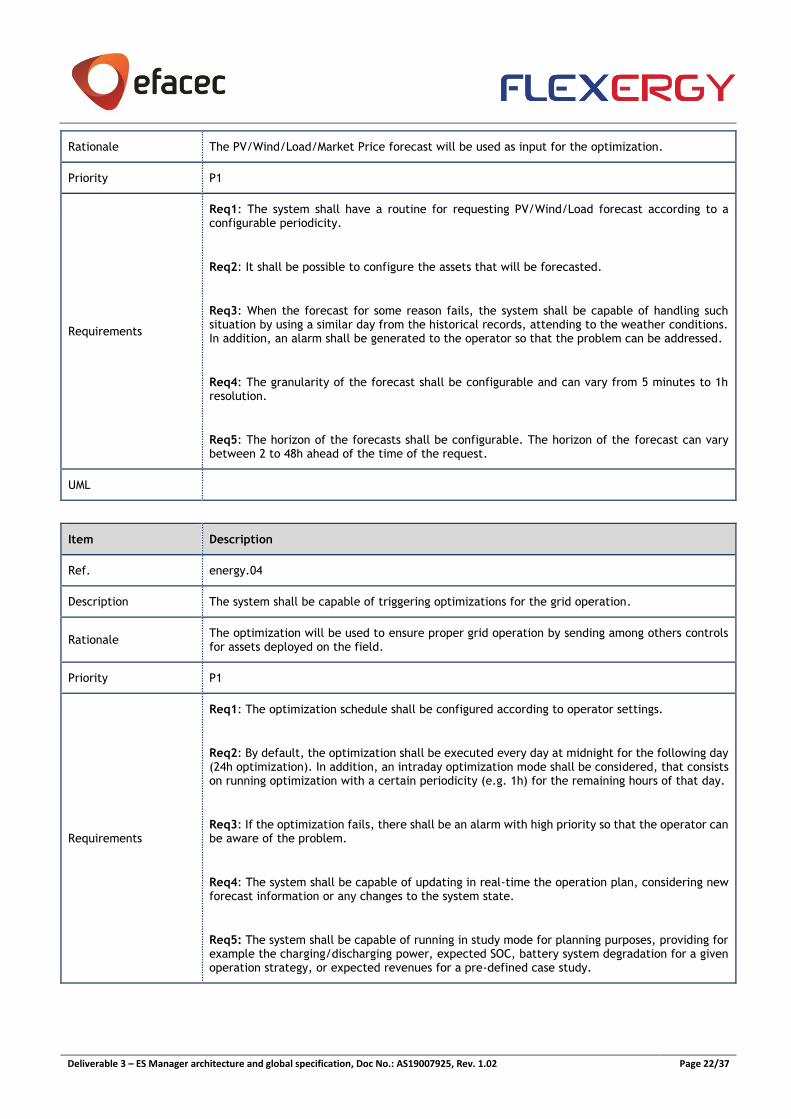
Rationale The PV/Wind/Load/Market Price forecast will be used as input for the optimization.
Priority P1
Requirements
Req1: The system shall have a routine for requesting PV/Wind/Load forecast according to a configurable periodicity.
Req2: It shall be possible to configure the assets that will be forecasted.
Req3: When the forecast for some reason fails, the system shall be capable of handling such situation by using a similar day from the historical records, attending to the weather conditions. In addition, an alarm shall be generated to the operator so that the problem can be addressed.
Req4: The granularity of the forecast shall be configurable and can vary from 5 minutes to 1h resolution.
Req5: The horizon of the forecasts shall be configurable. The horizon of the forecast can vary between 2 to 48h ahead of the time of the request.
UML
Item Description
Ref. energy.04
Description The system shall be capable of triggering optimizations for the grid operation.
Rationale The optimization will be used to ensure proper grid operation by sending among others controls for assets deployed on the field.
Priority P1
Requirements
Req1: The optimization schedule shall be configured according to operator settings.
Req2: By default, the optimization shall be executed every day at midnight for the following day (24h optimization). In addition, an intraday optimization mode shall be considered, that consists on running optimization with a certain periodicity (e.g. 1h) for the remaining hours of that day.
Req3: If the optimization fails, there shall be an alarm with high priority so that the operator can be aware of the problem.
Req4: The system shall be capable of updating in real-time the operation plan, considering new forecast information or any changes to the system state.
Req5: The system shall be capable of running in study mode for planning purposes, providing for example the charging/discharging power, expected SOC, battery system degradation for a given operation strategy, or expected revenues for a pre-defined case study.

Deliverable 3 – ES Manager architecture and global specification, Doc No.: AS19007925, Rev. 1.02 Page 23/37
UML
Item Description
Ref. energy.05
Description Automatic calculation of energy statistics.
Rationale Provide users dashboards and other means of information regarding grid operation.
Priority P2
Requirements
Req1: The system shall automatically calculate the monthly costs with energy based on the energy tariffs defined by the operator.
Req2: The system shall automatically calculate the monthly revenues resulting from the participation in DR events.
Req3: The system shall automatically calculate the following indexes for the whole grid and individual assets at least on a monthly and annually basis:
• Energy consumption from the grid and injected into the upstream network
• Energy produced by the local energy generations by source type (diesel, PV, etc)
• Energy consumed by EV charging stations
• Energy consumed by non-controllable loads
• Percentage of self-consumption and share of RES into the grid
• Amount of energy charged and discharged by the ESS
• Flexibility provided to the grid by the by flexible loads
• Number of charging and discharging cycles of the ESS
• Number of hours in zero net consumption
• Energy shifting from peak to off-peak hours and respective percentage
• Energy Costs Savings estimations
• Quality of Service Indices (SAIFI, SAIDI, etc)
• CO2 emissions and savings
Req4: It shall be possible to visualize the time evolution of the indices by enabling users to apply filters by date.
Req5: The system shall automatically calculate balancing reports of the grid namely comprising the following features:
• Energy Supplied per phase and total
• Energy Consumed per phase and total
• Technical Losses per phase and total

Deliverable 3 – ES Manager architecture and global specification, Doc No.: AS19007925, Rev. 1.02 Page 24/37
UML
Item Description
Ref. energy.06
Description Post-analysis performance, based on several identified Key Performance Indicators (KPIs).
Rationale
The use of KPIs simplifies the system overview and detects weakness and areas for improvements. The KPIs should provide objective evidence of progress towards achieving a desired result, and in self-adaptative software systems, the KPIs perform as monitored variables and determine whether a system is working as expected relative to its mandate or whether it should adapt its behaviour.
Priority P1
Requirements
Req1: The system shall automatically calculate the following KPIs for the whole grid on a monthly and annually basis:
• Smoothing performance
• Power profile predictability increase
• Maximize the overall revenue of the hybrid park
• Energy surplus management
• Reduced energy curtailment of RES
• Maximize profit
• Peak shaving/ flatten load
• Minimize the risks of power outage
• Levelized cost of energy (LCOE)
• Loss of load expectation (LOLE)
• Microgrid generation reliability
• Average cost reduction
• Pollutant emissions reduction
• Security of supply
• Grid congestion
• Effectiveness on BESS capacity allocation management for multiple services
• Frequency Control
• State of Health for individual ESS assets
• Cycle Benefits
• System global efficiency
• Number of cycles to failure (Rainflow method)
• BESS availability index
• Useful available energy
Req2: It shall be possible to visualize the time evolution of the KPIs by enabling users to apply filters by date.
UML
Item Description
Ref. energy.07
Description The system is capable of handling all types of events and alarms received from the field.
Rationale The micro-grid operation requires an online monitoring and control of the operation state.

Deliverable 3 – ES Manager architecture and global specification, Doc No.: AS19007925, Rev. 1.02 Page 25/37
Priority P3
Requirements
Req1: The system shall be capable of aggregating events from the field and aggregate them according to predefined rules.
Req2: The events may give rise to alarms that shall be visible to the operator and classified according the severity to the operation. In addition, the system shall notify the operator by email or other mean.
Req3: The system shall be capable of taking immediate actions on an autonomous fashion upon alarms were received from the field. For this purpose, there shall be a procedure list to adequate the operation to each particular scenario.
UML
Item Description
Ref. energy.08
Description The ES Manager shall have access to the grid state.
Rationale The grid state will be used as an input for the optimization operation plan.
Priority
Requirements
Req1: The grid state should be obtained through the SCADA.
Req2: The ES Manager shall be capable of knowing the availability of the generation sources present in its system (hybrid park or microgrid) for capacity market participation.
Req3: Every time a contingency problem is identified by the algorithm it shall be visible on the system an alarm and on the grid the respective zones with problems.
Req4: The power flow shall be executed with real time data retrieved from the field.
UML
Item Description
Ref. energy.9
Description Change the operation mode of the grid.
Rationale Provide operators the possibility of changing the operation mode of the grid.
Priority P1

Deliverable 3 – ES Manager architecture and global specification, Doc No.: AS19007925, Rev. 1.02 Page 26/37
Requirements
Req1: The system shall have a predefined set of operation modes available for the grid.
Req2: It shall be possible to schedule the operation of the grid in each of the available modes.
Req3: The system shall be responsible for ensuring a smooth transition between modes.
UML
Item Description
Ref. energy.10
Description The system shall be capable of participating in energy markets.
Rationale Participating in electricity markets can provide additional revenues to the owner.
Priority P1
Requirements
Req1: The system shall have access to information provided by market player regarding variable electricity prices, such as prices for off-peak periods and prices for peak periods, updated every 2-4 hours.
Req2: The system shall have access to ancillary services prices (balancing services, capacity management, congestion management, reactive power support) from the market player.
Req3: The system shall have access to information about the established transactions at the capacity market.
UML
Item Description
Ref. energy.11
Description The system shall be capable of receiving information from TSO about requirements and/or setpoints.
Rationale The system shall meet the requirements imposed by the system operator in order to ensure the security of the grid.
Priority P1
Requirements
Req1: The system shall have access to P(f) curves, provided by the TSO and to renewables forecast.
Req2: The operation plan can be updated in real time or minutes before, considering changes in
the TSO information.
Req3: The system shall be capable of meet the network constraints requirements.

Deliverable 3 – ES Manager architecture and global specification, Doc No.: AS19007925, Rev. 1.02 Page 27/37
UML
Item Description
Ref. energy.12
Description The operation plan shall be made for the next day.
Rationale The operation plan is made for the next day and is sent to the ES Controllers and to the RES Manager.
Priority P1
Requirements
Req1: The power setpoints shall be transmitted to the ES Controllers and to RES Manager for the next hour in a 15 minutes time frame, with the setpoint for each 15-minute interval.
Req2: The operation plan can be updated in real time, considering adjusts in the forecasted information or changes on the system state (exception updates to optimization parameters).
Req3: Considering the load forecast, market prices, weather and renewable forecast and the constraints of BESS.
Req4: The ES Manager shall be capable of calculating the reactive setpoints of the BESS and PV, according to system operator requirement.
Req5: The ES Manager shall be capable of fully comply with the EV load forecast by scheduling the operation plan of BESS and the PV power plant. The ES Manager realizes the operation plan in the day ahead and tries to avoid the power flow with the main grid.
UML
Item Description
Ref. energy.13
Description The ES Manager shall be capable of scheduling the operation plan of the BESS and the charging
operation strategy of EV’s.
Rationale The scheduling shall have the aim of minimizing the charging costs and/or avoiding system/ grid outages.
Priority

Deliverable 3 – ES Manager architecture and global specification, Doc No.: AS19007925, Rev. 1.02 Page 28/37
Requirements
Req1: The ES Manager shall be capable of defining the functionalities of the system, the priorities
of each function and the objective function.
Req2: The ES Manager shall also be capable of set priorities for the EV charging stations through
the information received, giving priority to the EV according to their respective SoC.
Req3: The ES Manager shall be capable of coordinate the EV’s charging strategy and scheduling
the BESS with the aim of minimizing charging costs and, more importantly, avoiding PPC limit
violations, resulting in constraints/ setpoints for charging period and charging pattern for each
EV.
Req4: The ES Manager shall be capable of prioritize the EV loads, determining the charging
pattern for each EV.
UML
Item Description
Ref. energy.14
Description The ES Manager shall be capable of managing and controlling the microgrid grid-connected.
Rationale The microgrid grid-connected management shall be performed trying to leverage the economic benefits
Priority
Requirements
Req1: The ES Manager shall be capable of performing peak shaving on a microgrid grid-connected
while trying to leverage the economic benefits.
Req2: The ES Manager schedules the BESS operation plan (charging and discharging) for the next
day, according to energy prices and load forecast.
Req3: The ES Manager shall manage and optimize the microgrid operation while trying to leverage
the economic benefits. The ES Manager shall be capable of calculating the active and reactive
setpoints of BESS, the active setpoints of the controllable loads, diesel gensets and RES.
Req4: The ES Manager shall be capable of calculating and ensuring a reserve power, with or without the diesel generator, in order to coper with demand variability responses in real-time.
Req5: The ES Manager shall be capable of optimizing and managing a microgrid operation
maintaining a zero power flow in the point of common coupling (PCC).
Req6: The ES Manager shall also be capable of limiting the active power on the PCC (allowing the
curtailment of RES).

Deliverable 3 – ES Manager architecture and global specification, Doc No.: AS19007925, Rev. 1.02 Page 29/37
UML
Item Description
Ref. energy.15
Description The ES Manager shall be capable of calculating the combination of services that deliver the
highest profit.
Rationale The ES Manager shall be capable of prioritizing the services and defining the conflict of interests between them.
Priority
Requirements
Req1: The ES Manager shall be capable of ensuring higher profit to the system through the
provision of multiple services.
Req2: The ES Manager shall be capable of knowing the availability of the generation sources (BESS and/or PV) that can provide reactive power support.
Req3: The ES Manager shall be capable of calculating the power reserve available for balancing services and the respective price for the submission of bids to the market player.
Req4: The ES Manager shall be capable of identifying the generation sources with problems/errors and the programmed interventions on the assets. With this type of information, the ES Manager can identify the generation sources available for market participation.
Req5: The ES Manager is also required to indicate the current maximum capacity of their units in the auction periods.
UML
Item Description
Ref. energy.16
Description The ES manager shall be capable of managing the operation plan while trying to leverage the economic benefits, considering existing constrains on the battery’s efficiency.
Rationale The ES Manager shall have a holistic vision of the factors that play a decisive role in the useful lifetime of the batteries for the optimization of the operational strategy.
Priority P1

Deliverable 3 – ES Manager architecture and global specification, Doc No.: AS19007925, Rev. 1.02 Page 30/37
Requirements
Req1: The ES Manager shall be capable of defining the functionalities of the system, the priorities
of each function and the weight of the maximization of the useful lifetime on the scheduling.
Req2: The ES Manager shall be capable of performing updates in real-time operation allowing BESS profile changes.
Req3: The ES Manager shall be capable of determining the system capacity for the use case in
use considering the boundaries that result from this particular use case.
UML
4. Communications
Item Description
Ref. com.01
Description The solution can communicate with all existing assets on the grid controlled by the ES Manager.
Rationale All the controllable assets that are available shall be considered for performing grid optimization.
Priority P1
Requirements
Req1: The system shall have at least the following protocols:
• IEC 61850
• IEC 60870-5-104
• Modbus
Req2: The system shall also consider the following protocols
• DLMS COSEM (IEC62056)
• TALQ
• OCPP 1.6
Req3: The system shall implement adequate processes for managing the information exchanged with the field devices – namely providing a retry mechanism for coping with communication failures
UML
Item Description
Ref. com.02
Description The solution can exchange information with third parties’ systems through standard protocols
Rationale The ES Manager is responsible for managing a part of the entire system. By communicating with others system, it is possible among others to provide energy services to the grid.
Priority P3

Deliverable 3 – ES Manager architecture and global specification, Doc No.: AS19007925, Rev. 1.02 Page 31/37
Requirements Req1: The system shall implement adequate processes for managing the information exchanged with other systems
UML
5. Infrastructure Management
Item Description
Ref. infra.01
Description The system is capable of automatically recognizing all the communicating devices that are installed on the field and are configured to exchange information with the ES Manager.
Rationale Provide operators a reliable overview over the AMI by enabling to continuously keep track over the communications state, make changes on the infrastructure and oversee the data collection process.
Priority P2
Requirements
Req1: The system shall indicate network topology status, summary status by service type/ device type and events type. It shall include the following features:
• Centralized management of communicating infrastructures
• Advanced Configuration and Visualizations
• Real time and historical information
• Network provisioning
• Performance monitoring
• Trouble shooting
Req2: The system shall support self-discovery and self-registry functionality to detect and register all kinds of devices that support such functionality.
Req3: The system shall support devices registration in bulk on a manual fashion, namely through uploading csv files.
Req4: The system shall allow inputs via manual data entry or batch processing for configuration of devices.
Req5: The system shall persist all data related with the existing assets (e.g. integration period, billing day, type of tariff configured, phase connection) on the field and being continually up to date, namely when a new configuration is sent.
UML
Item Description
Ref. infra.02
Description
The system provides automatic means of collecting data from the field.

Deliverable 3 – ES Manager architecture and global specification, Doc No.: AS19007925, Rev. 1.02 Page 32/37
Rationale
Ensure data collection on a cyclical basis allowing the operator to select the data to be collected and the respective frequency.
Priority P1

Deliverable 3 – ES Manager architecture and global specification, Doc No.: AS19007925, Rev. 1.02 Page 33/37
Requirements
Req1: The system shall be endowed with an AMI module that shall support bulk services for metering data acquisition when the field devices are not able to be configured with tasks for data reporting or when the data collection is to be managed on the system.
Req2: It shall be possible to send configurations in bulk for a list of devices. The bulk services for metering data acquisition shall have a defined periodicity that can be configured by the operator.
Req3: The module shall have embedded metering data acquisition performance reporting, such as statistics.
Req4: The system shall support on-request reading of any available information from any meter available in the infrastructure.
Req5: The ES Manager shall have access to grid measurements at PCC an shall also be capable of measuring the frequency in the PCC.
Req6: The system shall be capable of collecting at least the following metering data from sensors devices on the field:
Service Capture Objects Description Priority Frequency (min)
S29 - Load Profiles
AIi Active Energy Import Incremental 1
5
AEi Active Energy Export Incremental 1
R1i Reactive Energy QI Incremental 3
R2i Reactive Energy QII Incremental 3
R3i Reactive Energy QIII Incremental 3
R4i Reactive Energy QIV Incremental 3
AIiL1 Active Energy Import Incremental L1 2
AIiL2 Active Energy Import Incremental L2 2
AIiL3 Active Energy Import Incremental L3 2
AEiL1 Active Energy Export Incremental L1 3
AEiL2 Active Energy Export Incremental L2 3
AEiL3 Active Energy Export Incremental L3 3
S21 - Instantaneous Values
Pimp1 Active power (import) phase 1 1
<5
Pexp1 Active power (export) phase 1 1
Pimp2 Active power (import) phase 2 1
Pexp2 Active power (export) phase 2 1
Pimp3 Active power (import) phase 3 1
Pexp3 Active power (export) phase 3 1
Qimp1 Reactive power (import) phase 1 1
Qexp1 Reactive power (export) phase 1 2
Qimp2 Reactive power (import) phase 2 1
Qexp2 Reactive power (export) phase 2 2
Qimp3 Reactive power (import) phase 3 1
Qexp3 Reactive power (export) phase 3 2
L1v Voltage L1 phase 1 2

Deliverable 3 – ES Manager architecture and global specification, Doc No.: AS19007925, Rev. 1.02 Page 34/37
L2v Voltage L2 phase 2 2
L3v Voltage L3 phase 3 2
UML
6. Operation Management
Item Description
Ref. oper.01
Description The operator can change the operation mode of the grid.
Rationale The system will have different operation modes and optimization functions that can be chosen by the operator to best fit his needs.
Priority P2
Requirements
Req1: The system shall have the following operation modes:
• Grid-connected – increased self-consumption (Increase RES share)
• Grid-connected – tariff management (Consume or produce energy at the most advantageous time based on variable utility rates)
Req2: It shall be possible to choose the assets that will be considered on grid operation. Operator can disconnect assets from grid when for instance maintenance actions are planned being this reflected in terms overall operational management for short-term time horizons.
UML
7. System Management
Item Description
Ref. system.01
Description The system supplier has means of administrating the system in a centralised and easy fashion (super admin privileges).
Rationale Simplify installation process of the system and facilitate addition of users into the system.
Priority P3

Deliverable 3 – ES Manager architecture and global specification, Doc No.: AS19007925, Rev. 1.02 Page 35/37
Requirements
Req1: The system shall have an administration panel that enables the following:
• Manage user licences and permissions
• Add new users to the system
• Change the functionalities available to users
• To configure trial versions
• Visualize help requests sent by users
• Configure user’s payment plans and bank account details
Req2: The administration panel shall be prepared to display business metrics and analytics or to export weekly data which can be used to create reports.
UML

Deliverable 3 – ES Manager architecture and global specification, Doc No.: AS19007925, Rev. 1.02 Page 36/37
Appendix B - Non-Functional Requirements
1. System Availability
Item Description
Ref. sysavailability.01
Description The system has high availability being capable to recover after a failure condition.
Rationale System downtime implies impacts on grid operation.
Priority P3
Requirements
Req1: The system shall be prepared to be deployed under different redundancy concepts, namely:
• Hot-standby
• N Modular Redundancy
Req2: The system shall have a distributed database that is continually being replicated throughout the time.
Req3: The system shall be prepared for performing database duplication on cyclical basis in order to ensure data backups.
UML
Item Description
Ref. sysavailability.02
Description The system should define contingency plans, considering the main controllable assets.
Rationale Promoting the resilience of the ES Manager.
Priority
Requirements
UML
2. System Security
Item Description
Ref. syssecurity.01
Description The system has means of ensuring security access and data privacy.

Deliverable 3 – ES Manager architecture and global specification, Doc No.: AS19007925, Rev. 1.02 Page 37/37
Rationale Guarantee the data from users is not accessed from unauthorized third parties.
Priority P2
Requirements
Req1: This module shall provide functionality for secure storage and processing of security keys & certificates, two-layer end-to-end encryption between the system and field devices, symmetric encryption keys for field devices, and an AES128 encryption algorithm (or similar) throughout the entire system.
UML