delta 1010 user guide · 2012-12-14 · 10 | delta 1010 user guide delta system overview 7 analog...
TRANSCRIPT
10 in 10 out PCI Digital Recording System with S/PDIF
User Guide
Table of Contents
Introduction . . . . . . . . . . . . . . . . . . . . . . . . . . . . . . 3
What’s in the Box? . . . . . . . . . . . . . . . . . . . . . . . . . . 3
About the Delta 1010 Digital Recording System . . . . . . . . . . . 4
Product Features & Specifications . . . . . . . . . . . . . . . . . . 5
Minimum System Requirements . . . . . . . . . . . . . . . . . . . 6
Hardware Controls and Indicators . . . . . . . . . . . . . . . . . . 6Rack Unit Front Panel . . . . . . . . . . . . . . . . . . . . . . . . . . 6
Rack Unit Back Panel . . . . . . . . . . . . . . . . . . . . . . . . . . . 7
PCI Host Adapter Card . . . . . . . . . . . . . . . . . . . . . . . . . . 8
Delta System Overview . . . . . . . . . . . . . . . . . . . . . . . . 10Analog Inputs/Outputs . . . . . . . . . . . . . . . . . . . . . . . . . . 10
The Digital Monitor Mixer . . . . . . . . . . . . . . . . . . . . . . . . . 10
The Patchbay / Router . . . . . . . . . . . . . . . . . . . . . . . . . . 11
Synchronization . . . . . . . . . . . . . . . . . . . . . . . . . . . . . 11
Using Delta 1010 with your Audio Software . . . . . . . . . . . . . 12Audio Inputs . . . . . . . . . . . . . . . . . . . . . . . . . . . . . . 12
Audio Outputs . . . . . . . . . . . . . . . . . . . . . . . . . . . . . 13
Control Panel Software . . . . . . . . . . . . . . . . . . . . . . . 14Delta Control Panel for Windows XP . . . . . . . . . . . . . . . . . . . . . 14
Monitor Mixer Tab . . . . . . . . . . . . . . . . . . . . . . . . . . . 14Patchbay/Router Tab . . . . . . . . . . . . . . . . . . . . . . . . . . 17Hardware Settings Tab . . . . . . . . . . . . . . . . . . . . . . . . . 18S/PDIF Tab . . . . . . . . . . . . . . . . . . . . . . . . . . . . . 22Bass Management Tab . . . . . . . . . . . . . . . . . . . . . . . . . 25About Tab . . . . . . . . . . . . . . . . . . . . . . . . . . . . . 26Additional Control Panel Features . . . . . . . . . . . . . . . . . . . . . . 26
Control Panel Software for Mac OS X . . . . . . . . . . . . . . . . 27Monitor Mixer Tab . . . . . . . . . . . . . . . . . . . . . . . . . . . . 27
Patch Bay Tab . . . . . . . . . . . . . . . . . . . . . . . . . . . . . 30
Hardware Settings Tab . . . . . . . . . . . . . . . . . . . . . . . . . . 31
S/PDIF Tab . . . . . . . . . . . . . . . . . . . . . . . . . . . . . . 33
About Tab . . . . . . . . . . . . . . . . . . . . . . . . . . . . . . . 36
Additional Control Panel Features . . . . . . . . . . . . . . . . . . . . . . 36
Troubleshooting . . . . . . . . . . . . . . . . . . . . . . . . . . . . 38
Technical Specifications . . . . . . . . . . . . . . . . . . . . . . . 41
Technical Info . . . . . . . . . . . . . . . . . . . . . . . . . . . . . 42
Appendix . . . . . . . . . . . . . . . . . . . . . . . . . . . . . . . 43Appendix A: Clocking . . . . . . . . . . . . . . . . . . . . . . . . . . 43
Warranty Terms and Registration . . . . . . . . . . . . . . . . . . 44

| 3Delta 1010 User Guide
Introduction
1C ongratulations on your purchase of the Delta 1010 audio interface. Delta 1010
is the top product in M-Audio’s line of award winning “Delta” digital recording systems and has helped set the standard for the solid hardware design and robust driver technology found in other members of the Delta family.
Even if you are experienced with digital recording, please take a moment to read through this manual. It will give you valuable information about the Delta 1010 interface and will help you get the most out of your new purchase. You may also want to refer to your audio software’s documentation to better understand how Delta 1010 can be integrated with the application. Your experience and enjoyment with the interface will be greatly enhanced by a good working knowledge of your equipment.
What’s in the Box?
2Your Delta 1010 package contains:
< Delta 1010 rack-mount interface
< PCI Host Adapter card
< Host connector cable
< 9V AC 3A in-line power supply unit
< Printed Quick Start Guide
< Delta Series CD-ROM containing drivers, Control Panel software, and documentation

Delta 1010 User Guide4 |
About the Delta 1010 Digital Recording System
3D elta 1010 is a professional audio interface with a total of 10 inputs and 10
outputs. The interface features eight 1/4” balanced/unbalanced analog inputs and outputs as well as a pair of coaxial (RCA) S/PDIF I/O. Delta 1010 can create pristine 24-bit recordings at sampling rates of up to 96 kHz.
Connect line-level audio sources (i.e., keyboards, mixers, preamplifiers, etc.) to the 1/4” input jacks on the rear of the interface. Set the operating line level for each input using the +4/-10 switch located next to each jack. Connect your DAT recorder, MiniDisc player, or other digital device to Delta 1010’s S/PDIF ports on the PCI Host card. Control all routing and hardware settings using the Control Panel software.
The sturdy 1U rack-mount chassis houses all of the A/D and D/A converters, keeping them away from the electrically noisy environment inside your computer and assuring the best audio performance. The rack unit features Word Clock I/O connectors, which allow you to synchronize Delta 1010 with all of your other Word Clock capable devices. Also, the interface features MIDI input and output ports, allowing you to connect MIDI-capable devices (synthesizers, drum machines, etc.) to your computer or to synchronize external devices with your interface using a sync protocol such as MIDI Time Code (MTC).
Finally, the Delta 1010 PCI Host Adapter card features a flexible digital mixer. This mixer handles routing within the interface and gives you control over volume, pan, solo, and mute just like on a hardware mixer used for monitoring.

| 5Delta 1010 User Guide
Product Features & Specifications
4< 10-input, 10-output recording interface
< Supports up to 24-bit, 96kHz operation
< PCI host card with DSP for digital mixing
< Sturdy rack-mounted I/O interface
< Eight balanced/unbalanced analog inputs and outputs on 1/4” connectors with +4dB or -10dB operation (operating levels are individually selectable for each channel)
< MIDI, Word Clock, and S/PDIF inputs and outputs
< Balanced or unbalanced operation
< High dynamic range: D/A 114dB, A/D 109dB (A-weighted)
< Low distortion (measured THD @ 0dBFS): A/D 0.001%, D/A 0.0015%.
< All data paths support up to 24bit/96kHz performance.
< Control Panel software for mixing, routing, and monitoring capabilities
< Sample-accurate hardware sync allows linking of up to four Delta 1010 interfaces in one computer
< Windows XP drivers for ASIO/ASIO2, WDM, DirectX, MME, and GSIF/GSIF2 protocols.
< Mac OS X drivers for Core Audio and Core MIDI

Delta 1010 User Guide6 |
Minimum System Requirements*
5Windows* Mac*
< Windows XP** Service Pack 2
< Pentium III 933MHz
< 256 MB RAM
< G3† processor using Mac OS X 10.3.9 with 256 MB RAM
< G4† processor using Mac OS X 10.3.9 / 10.4.8 or higher with 512 MB RAM
*M-Audio suggests that you also check the minimum system requirements for your software, as they may be greater than Delta 1010’s requirements.
**Home and Professional Edition only. Windows Media Center Edition is not currently supported
†G3/G4 accelerator cards not supported.
Hardware Controls and Indicators
6Rack Unit Front Panel:
�
� � � �
1 Power Indicator LED (Power): This LED illuminates when the interface is powered on and has established communication with your host computer.
2 MIDI Input LED: This LED illuminates when MIDI data is received at the MIDI Input Jack 4 .
3 MIDI Output LED: This LED illuminates when MIDI data is sent from the MIDI Output jack 5 .

| 7Delta 1010 User Guide
4 MIDI Input Jack (MIDI In): This standard 5-pin MIDI connector accepts signals from any MIDI compatible device such as a keyboard or control surface.
5 MIDI Output Jack (MIDI Out): This standard 5-pin MIDI connector transmits signals to any MIDI compatible device such as a synthesizer, sound module, or drum machine.
Rack Unit Back Panel:
��
��
���� � �
��
6 Word Clock In (WORDCLOCK In): Delta 1010 is capable of synchronizing its sample rate clock with that of an incoming word clock signal using this BNC input.
7 Word Clock Out (WORDCLOCK Out): This BNC output transmits a Word Clock signal that is in sync with the present sample rate clock of Delta 1010.
The Word Clock input and outputs (6, 7) are designed to work with 75-ohm coaxial BNC cables. Be sure to use 75-ohm BNC cables to ensure good performance.
8 Host Cable Connector (HOST CABLE): Use the supplied 25-pin host cable to connect this jack to the Delta 1010 PCI Host Adapter card.
IMPORTANT: Do not connect the PCI Host Adapter card and rack-mount portion of the interface when your computer is powered on. Doing so may damage the rack-mount interface and/or the PCI card. Only connect (or disconnect) the PCI card and rack-mount unit when your computer is powered off.
9 Analog Inputs 1-8 (INS): These eight 1/4” jacks accept line-level signals from any balanced (TRS) or unbalanced (TS) device. The sensitivity of each input can be configured using the +4/-10 switch (11) to the left of each input.
10 Analog Outputs 1-8 (OUTS): These eight 1/4” jacks output balanced, line-level signals for monitoring, mixing, or processing with external devices. The sensitivity of these outputs can be configured using the +4/-10 switch (11) to the left of each output. Note that these balanced outputs are fully compatible with unbalanced devices as well.

Delta 1010 User Guide8 |
11 Signal-Level +4/-10 Switch: This button sets the operating signal level for each analog input and output channel. When this switch is in the out position, its associated channel will operate at the professional +4dBu standard; when the switch is pressed, the channel will operate at -10dBV.
About the +4/10 button: The +4dBu standard is used by most mixers, preamplifiers, and other professional audio devices with balanced outputs. Devices with unbalanced outputs commonly use the -10dBV standard. If you’re not sure about the operating level of a device you’ve connected to your Delta 1010, refer to the device’s user manual.
12 Power Jack (9V AC): Connect the supplied 9V AC power supply to this jack.
IMPORTANT: Do NOT connect a DC power supply to this jack. Doing so may damage the interface. Delta 1010 requires a 9V AC supply, with at least 3 ampere capability.
PCI Host Adapter Card:
����
��
13 Coaxial S/PDIF Input: This RCA connector allows Delta 1010 to receive a stereo S/PDIF signal from any device with a coaxial (RCA) S/PDIF digital output such as a DAT machine, MiniDisc player, or external A/D converter.
NOTE: The S/PDIF Input is only available when Delta 1010’s Master Clock source is set to “S/PDIF” or “Word Clock.”
14 Coaxial S/PDIF Output: This RCA connector lets you send a stereo S/PDIF signal to any device that can receive a coaxial (RCA) S/PDIF signal such as a DAT recorder, MiniDisc recorder, or external D/A converter.
15 Host Cable connector: Use the supplied Host Cable to connect this jack to the Host Cable Connector (8) on the rack-mount portion of the Delta 1010 interface.
| 9Delta 1010 User Guide
IMPORTANT: Do not connect the PCI Host Adapter card to the rack-mount chassis when your computer is powered on. Doing so may damage the interface. Only connect (or disconnect) the PCI card and rack-mount unit when your computer is powered off.
IMPORTANT: The Host Cable connector features a 25-pin jack that looks like the parallel (printer) port connection found on some computers. If your computer has a parallel port, be careful not to confuse these two connectors and do not attempt to connect the PCI Host Adapter card to anything other than the rack-mount portion of the Delta 1010 interface. Doing so may damage the interface.
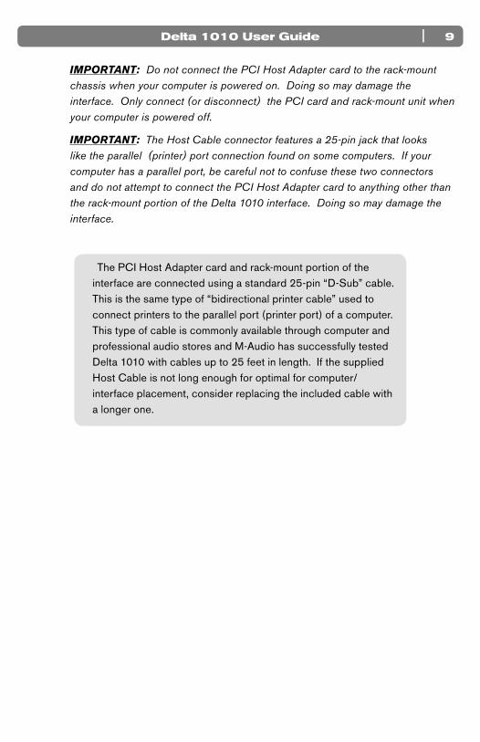
The PCI Host Adapter card and rack-mount portion of the interface are connected using a standard 25-pin “D-Sub” cable. This is the same type of “bidirectional printer cable” used to connect printers to the parallel port (printer port) of a computer. This type of cable is commonly available through computer and professional audio stores and M-Audio has successfully tested Delta 1010 with cables up to 25 feet in length. If the supplied Host Cable is not long enough for optimal for computer/interface placement, consider replacing the included cable with a longer one.
Delta 1010 User Guide10 |
Delta System Overview
7Analog Inputs/OutputsDelta 1010’s analog inputs and outputs allow you to record a variety of audio sources and to playback your recordings to many destinations. On the rear of the interface, you will find eight 1/4” inputs and eight 1⁄4” outputs with independent +4/-10 signal level buttons (11) next to each jack. Be sure to set these switches properly to ensure the best possible sound quality.
All of the analog inputs and outputs on the rear of the Delta 1010 are balanced 1/4” jacks. These jacks allow connection to either balanced (TRS) or unbalanced (TS) line-level devices.
NOTE: Since Delta 1010 does not have microphone pre-amplifiers built into the inputs, it is not possible to use a microphone that is connected directly to the interface. To record a microphone, you must first pass the microphone signal through a microphone preamplifier (such as the M-Audio TAMPA) and connect the preamplified line-level or S/PDIF output to the input of the Delta 1010.
The Digital Monitor Mixer
Delta 1010 features a hardware digital audio mixer built into its PCI Host Adapter card. This mixer accepts digital audio from all hardware inputs and all software audio outputs, mixes them with 36-bit internal precision, and then provides the mixed signal to analog outputs 1-2 and/or the S/PDIF outputs for monitoring purposes. While the mixer is primarily intended to be used for creating monitor mixes, it may also be used for stereo mixing since its output can be recorded back into your audio application. The digital audio mixer is configured and controlled by the included Control Panel software.

| 11Delta 1010 User Guide
The Patchbay / Router
In addition to the built-in Monitor Mixer, Delta 1010 also provides virtual signal patching and routing capabilities. This “Patchbay/Router” is accessed through the Control Panel software and allows a variety of sources (including your music software, the analog and digital inputs of the interface, or the Monitor Mixer output) to be linked to various physical outputs on the interface. This flexible routing capability allows you to use Delta 1010 in a variety of different situations and to quickly reconfigure the interface without having to physically disconnect and reconnect the hardware inputs and outputs on the rear of the interface.
Synchronization
For proper operation, all digitally interconnected audio systems (including the Delta 1010 interface) must be synchronized to a single master clock. If your digital audio systems are not configured in this way, you are likely to hear clicks, pops, and other glitches in your audio streams. The Control Panel software allows you to synchronize the interface to its internal clock or to “lock” to an external clock source being received at the S/PDIF or Word Clock inputs. This allows you to easily install the Delta 1010 hardware into any kind of digital environment where S/PDIF or Word Clock are being used.

Delta 1010 User Guide12 |
Using Delta 1010 with your Audio Software
8A fter Delta 1010’s hardware and drivers have been installed, you may need to
select or enable the interface in your audio software before you can begin recording. This process is usually done through a “setup” or “audio preferences” menu within the program. Refer to your software’s documentation to learn how to do this.
Audio Inputs:
Once your audio software is configured, you may begin recording with the interface. The following list should help you associate the input names displayed by your audio software with Delta 1010’s corresponding physical inputs:
Display Name Corresponding Inputs
Delta 1010 1/2 Analog Inputs 1/2
Delta 1010 3/4 Analog Inputs 3/4
Delta 1010 5/6 Analog Inputs 5/6
Delta 1010 7/8 Analog Inputs 7/8
Delta 1010 9/10 S/PDIF Input
*Delta 1010 11/12 *Summed Monitor Mixer Signal
NOTE: There may be slight variations in the naming of inputs when using certain audio applications. For example, an input pair may be labeled “ASIO 1-2” instead of “Delta 1010 1/2.” Furthermore, some programs may break down the inputs listed above into individual “left” and “right” mono channels. In this case, the software may display the inputs as “Left Delta 1010 1,” “Right Delta 1010 2,” etc. Refer to your application’s user guide to learn more about how inputs are labeled.
“Delta 1010 1/2” through “Delta 1010 7/8” correspond to analog inputs 1-8 on the rear of the rack-mount interface.
“Delta 1010 9/10” corresponds to the red S/PDIF input on the PCI Host Adapter card.
NOTE: The S/PDIF Input will not accept incoming signals if Delta 1010’s Clock Source is set to “Internal Xtal” in the Control Panel. To ensure proper operation, set the Clock Source to S/PDIF and make sure that the connected source device is configured as clock master. Please see the Digital Synchronization and Multi-Device Setup Guide found at http://www.m-audio.com for more information.
*“Delta 1010 11/12” is the output of the hardware Monitor Mixer on the PCI card and can be selected if you wish to record the combined physical and virtual inputs (audio returning from your recording software) of the Monitor Mixer.
| 13Delta 1010 User Guide
Audio Outputs:
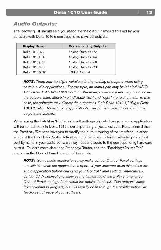
The following list should help you associate the output names displayed by your software with Delta 1010’s corresponding physical outputs:
Display Name Corresponding Outputs
Delta 1010 1/2 Analog Outputs 1/2
Delta 1010 3/4 Analog Outputs 3/4
Delta 1010 5/6 Analog Outputs 5/6
Delta 1010 7/8 Analog Outputs 7/8
Delta 1010 9/10 S/PDIF Output
NOTE: There may be slight variations in the naming of outputs when using certain audio applications. For example, an output pair may be labeled “ASIO 1-2” instead of “Delta 1010 1/2.” Furthermore, some programs may break down the outputs listed above into individual “left” and “right” mono channels. In this case, the software may display the outputs as “Left Delta 1010 1,” “Right Delta 1010 2,” etc. Refer to your application’s user guide to learn more about how outputs are labeled.
When using the Patchbay/Router’s default settings, signals from your audio application will be sent directly to Delta 1010’s corresponding physical outputs. Keep in mind that the Patchbay/Router allows you to modify the output routing of the interface. In other words, if the Patchbay/Router default settings have been altered, selecting an output port by name in your audio software may not send audio to the corresponding hardware output. To learn more about the Patchbay/Router, see the “Patchbay/Router Tab” section in the Control Panel chapter of this guide.
NOTE: Some audio applications may make certain Control Panel settings unavailable while the application is open. If your software does this, close the audio application before changing your Control Panel setting. Alternatively, certain DAW applications allow you to launch the Control Panel or change Control Panel settings from within the application itself. This process varies from program to program, but it is usually done through the “configuration” or “audio setup” page of your software.
Delta 1010 User Guide14 |
Control Panel Software
9D elta 1010 is a powerful audio interface with a variety of options and parameters
relating to its operation. After installing the Delta 1010 drivers, you can use the Control Panel software to configure the various parameters of the interface. Since the appearance and functionality of the Control Panel varies slightly between Windows XP and Mac OS X, each operating system is covered separately in this guide.
Delta Control Panel for Windows XP
This section covers the Control Panel for Windows XP users. Mac OS X users should skip to the following section of this User Guide to learn about the Mac OS X Control Panel.
To access the Delta Control Panel in Windows, double-click the M-Audio icon in the system tray, or click Start > Control Panel and double-click the Delta 1010 Control Panel icon. Your audio software may also allow you to access the Control Panel from within the application itself.
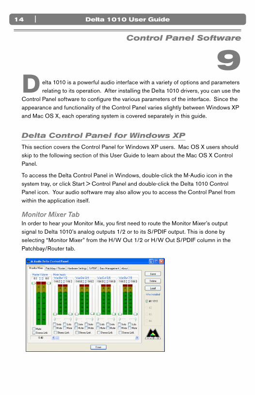
Monitor Mixer TabIn order to hear your Monitor Mix, you first need to route the Monitor Mixer’s output signal to Delta 1010’s analog outputs 1/2 or to its S/PDIF output. This is done by selecting “Monitor Mixer” from the H/W Out 1/2 or H/W Out S/PDIF column in the Patchbay/Router tab.

| 15Delta 1010 User Guide
Monitor Mixer is the first tab that appears when the Control Panel is opened. This tab controls the digital mixer built into the Delta 1010 PCI Host Adapter card and has the following controls and indicators:
< LEVEL FADERS: Each volume fader is controlled by dragging the vertical slider with your mouse, or by clicking on the small up and down arrows above the faders (these “fine adjustment” arrows will raise or lower fader in 0.5dB increments). The current fader setting is displayed numerically above each fader.
Note that the Monitor Mixer has no gain and that its faders only attenuate (reduce) incoming signal levels once the signals have been converted to digital audio. The highest setting is 0dB (or ‘Unity Gain’) and allows signals to pass through unaffected. The default fader setting (-144dB) is the quietest setting and will essentially mute the channel.
NOTE: To make precise edits to a level or pan slider, click a slider to select it and use the arrow keys on your computer keyboard to move the selected slider.
< VU METERS: Each channel features a VU meter that indicates audio levels in “dB relative to full-scale.” This means that the loudest possible signal is referred to as “0dB” and a signal that is, for example, 12dB lower than the maximum loudness is referred to as “-12dB.”
The meters are color-coded into three sections: green, yellow and red. The green section represents the “safe” zone and ranges from approximately -48dB to -12dB. The yellow section ranges from -12dB to -3dB, and the red section ranges from -3dB to 0dB. Once a signal reaches (or exceeds) 0dB, it means the signal is overloading Delta 1010’s analog-to-digital or digital-to-analog converters and is “clipping” or distorting. Unlike the analog distortion found on guitar amplifiers and effects pedals, digital distortion is harsh, unmusical, and should generally be avoided.
Therefore, we recommend setting input and output levels so that the loudest peaks of your incoming signal will reach the top of the yellow range but will generally not enter into the red zone. Technically, your signal may enter into the red zone without resulting in distortion but this not generally recommended since it leaves very little headroom. In other words, one loud note during a performance or mix may result in a severely distorted recording or mix.
< MASTER VOLUME: The Master Volume section is found to the left of the Mixer Input section. These faders control the overall output level of the Monitor Mixer. The adjacent VU meters indicate the Monitor Mixer’s output levels and are “post-fader.” This means changes to the master fader will affect the levels displayed on the VU meters.
Delta 1010 User Guide16 |
< MIXER INPUTS: The Mixer Input channels are found to the right of the Master Volume section. These channels receive audio directly from Delta 1010’s analog and digital inputs as well as from the outputs of your audio software. This allows you to mix your incoming signals with your previously recorded tracks to create a hardware monitor mix that is virtually free of the delay (or “latency”) that is inherent in all software-based digital mixing systems.
NOTE: The VU meters in the Mixer Input section are “pre-fader.” This means that the meters display the incoming signal before the signal passes through the faders. Since the VU meters are pre-fader, making adjustments to a fader will have no impact on the levels displayed on its corresponding meter. The input meters have been set up in this way so that you will always see the “true” incoming signal levels. This helps you set optimum output levels on devices that are connected to Delta 1010, regardless of how the faders may be set up in the Monitor Mixer.
Because of the large number of mixer inputs, not all inputs are displayed simultaneously. The scroll bar at the bottom of the Mixer Input section allows you to scroll through the various inputs.
The inputs are labeled (from left to right): “WavOut 1/2” through “WavOut 7/8,” then “WavOut S/PDIF.” These inputs accept the digital audio streams being sent from your audio application to the driver devices with those same names. These names begin with “WavOut” to remind you that these are software streams and may not necessarily be routed to any physical outputs (see Patchbay/Router Page).
Further to the right are more channels, labeled “H/W In S/PDIF” and “H/W In 1/2” through “H/W In 7/8.” These mixer inputs are audio streams from the physical Delta 1010 hardware inputs.
< PAN: Each mixer input may be individually panned from left to right using the horizontal slider beneath the channel’s volume fader.
< SOLO: Each mixer input channel features a “Solo” checkbox. When a channel’s Solo box is checked, all other channels will be temporarily muted and only the “soloed” channel will be heard. Deactivating all solo boxes will return all input channels to their previous mute/unmute states.
Note that it is possible to solo more than one channel at a time on the Monitor Mixer. If more than one channel is soloed, all solo channels will be heard while all channels that are not soloed will be muted. To return to normal operation, uncheck all Solo boxes.
| 17Delta 1010 User Guide
< MUTE: Every Monitor Mixer channel has a “Mute” checkbox. When this box is checked, its associated channel will not be routed to the stereo output and will not be heard in the monitor mix. When the box is unchecked, its associated channel will be routed to the mixer’s output.
< STEREO LINK: All of the Monitor Mixer’s channel pairs have a “Stereo Link” checkbox. When this box is checked, the left/right faders move together so that the channels may be adjusted as a stereo pair. When this box is unchecked, the faders can be adjusted independently.
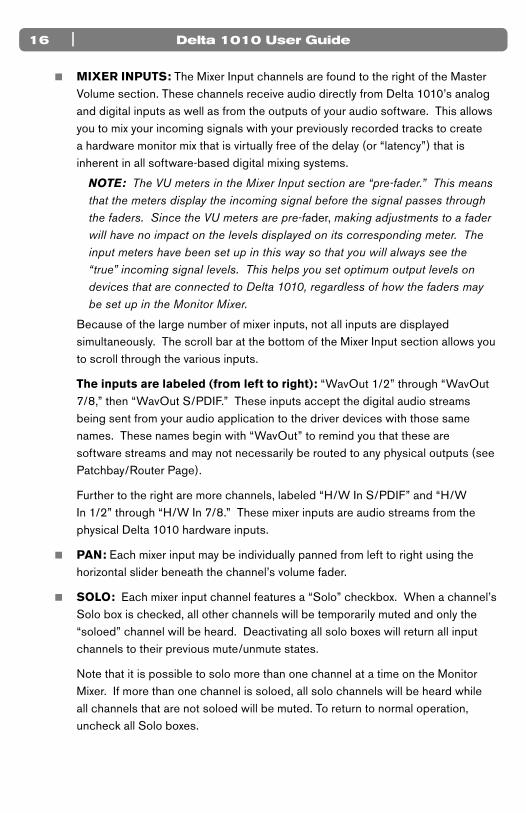
Patchbay/Router Tab
Each column in the Patchbay/Router tab represents a physical output pair on your Delta 1010 interface. The radio buttons in each column allow you to select the audio source for that physical ouput.
To use the Patchbay/Router, first locate the Delta 1010 output that you’d like to use—the outputs are listed across the top of the tab. H/W Out 1/2, 3/4, 5/6, and 7/8 correspond to analog outputs 1-8 while H/W Out S/PDIF corresponds to the S/PDIF output.
Next, click the radio button for the input source you’d like to connect to your chosen output. The available options listed in the column below each output. Delta 1010 will now route that audio source to your selected output.
The input sources are described below:
< WavOut 1/2 through 7/8: These inputs correspond to the outputs of your audio software.
< Monitor Mixer: This input corresponds to the output of the Delta 1010 Monitor Mixer. This audio source can only be routed to analog outputs 1-2 and/or the S/PDIF output.
Delta 1010 User Guide18 |
< S/PDIF In: This input corresponds to the S/PDIF input.
< S/PDIF In (L/R Rev.): This corresponds to the S/PDIF input but swaps the left and right channels.
< H/W In 1/2 through 7/8: These inputs correspond to the hardware analog inputs of the Delta 1010 interface.
TIP: To restore the Router/Patchbay to its default settings, select the topmost radio button in each column.
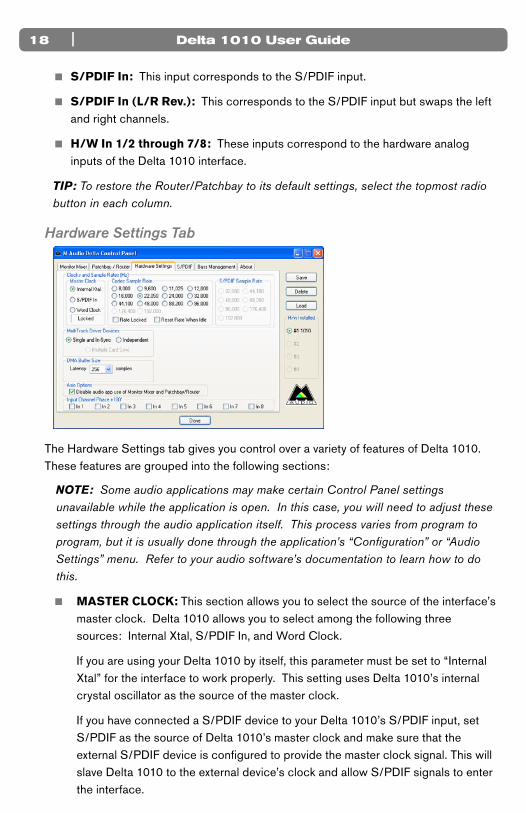
Hardware Settings Tab
The Hardware Settings tab gives you control over a variety of features of Delta 1010. These features are grouped into the following sections:
NOTE: Some audio applications may make certain Control Panel settings unavailable while the application is open. In this case, you will need to adjust these settings through the audio application itself. This process varies from program to program, but it is usually done through the application’s “Configuration” or “Audio Settings” menu. Refer to your audio software’s documentation to learn how to do this.
< MASTER CLOCK: This section allows you to select the source of the interface’s master clock. Delta 1010 allows you to select among the following three sources: Internal Xtal, S/PDIF In, and Word Clock.
If you are using your Delta 1010 by itself, this parameter must be set to “Internal Xtal” for the interface to work properly. This setting uses Delta 1010’s internal crystal oscillator as the source of the master clock.
If you have connected a S/PDIF device to your Delta 1010’s S/PDIF input, set S/PDIF as the source of Delta 1010’s master clock and make sure that the external S/PDIF device is configured to provide the master clock signal. This will slave Delta 1010 to the external device’s clock and allow S/PDIF signals to enter the interface.
| 19Delta 1010 User Guide
If you have connected a Word Clock device to your Delta 1010 and would like to use that device’s clock as the master clock source, select Word Clock as the source of Delta 1010’s master clock. This will slave Delta 1010 to the external word clock device’s clock.
NOTE: It is possible to synchronize Delta 1010 through its Word Clock input while simultaneously receiving signals at the S/PDIF input. However, all connected digital input devices need to be synchronized to the same clock source before the digital signals enter the Delta 1010 interface.
The box below the radio buttons indicates whether Delta 1010 is clocking to a valid internal or external clock. It states “Locked” when the interface is locked to a clock and “Unlocked” when Delta 1010 is not receiving a valid clock signal.
For more information about Clocking, please see Appendix A: Clocking at the end of this guide and/or read the Digital Synchronization and Multi-Device Setup Guide found on http://www.m-audio.com..
< CODEC SAMPLE RATE: This section lets you select the sampling rate of the interface and determine the rate at which all of the digital components of Delta 1010 (A/D and D/A converters, Monitor Mixer, etc.) will operate. This section also includes the following checkboxes:
• Rate Locked: The “Rate Locked” checkbox allows you to force Delta 1010 to operate at the chosen sample rate. This will prohibit audio applications from attempting to operate Delta 1010 at a sample rate other than the one selected in the Control Panel.
By default, this box is left unchecked and allows your audio software to choose any sample rate that is supported by the Delta 1010 hardware.
• Reset Rate When Idle: Check this box if you would like Delta 1010 to default to the chosen sample rate when the interface is not actively being used by your audio application.
NOTE: The Reset Rate When Idle box is provided as a convenience for users who wish to play all sounds (such as Windows system sounds (typically 22kHz), the output of your computer’s CD player (44.1kHz) or DVD player software (typically 48kHz), etc.) through the Delta 1010 hardware. However, please be advised that doing so may cause the clock rate to be changed, and this may result in a sample rate mismatch between running audio applications. As a general rule of thumb, we recommend users to turn off all system sounds and to only use Delta 1010 with their audio software if possible. This will prevent possible issues related to undesired pitch or speed changes of digital audio.
NOTE: Certain sample rate options are “grayed out” because Delta 1010 does not support these rates.
Delta 1010 User Guide20 |
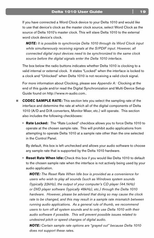
< S/PDIF SAMPLE RATE: When using the S/PDIF input as your master clock source, use these radio buttons to indicate the expected incoming sample rate. Your selection here will be the only sample rate available to your audio software. This ensures that recordings will be made at the proper rate.
NOTE: These radio buttons are only available when Master Clock is set to “S/PDIF In.”
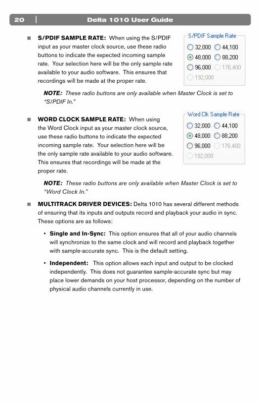
< WORD CLOCK SAMPLE RATE: When using the Word Clock input as your master clock source, use these radio buttons to indicate the expected incoming sample rate. Your selection here will be the only sample rate available to your audio software. This ensures that recordings will be made at the proper rate.
NOTE: These radio buttons are only available when Master Clock is set to “Word Clock In.”
< MULTITRACK DRIVER DEVICES: Delta 1010 has several different methods of ensuring that its inputs and outputs record and playback your audio in sync. These options are as follows:
• Single and In-Sync: This option ensures that all of your audio channels will synchronize to the same clock and will record and playback together with sample-accurate sync. This is the default setting.
• Independent: This option allows each input and output to be clocked independently. This does not guarantee sample-accurate sync but may place lower demands on your host processor, depending on the number of physical audio channels currently in use.
| 21Delta 1010 User Guide
• Multiple Card Sync: If you are using multiple Delta cards in one system, this option allows you to synchronize all cards to the same master clock through the computer’s PCI buss
NOTE: The “Multiple Card Sync” setting is only recommended if you are using a Delta card that does not have S/PDIF or Word Clock connections. For example, since Delta 44 does not have S/PDIF I/O, if you would like to synchronize your Delta 1010 with a Delta 44 installed in the same computer, you should use “Multiple Card Sync.” However, if you have multiple Delta cards with S/PDIF or Word Clock connectors (such as two Delta 1010s), we recommend synchronizing clocks through the S/PDIF or Word Clock connections as this method provides more robust synchronization. See Appendix A: Clocking of this guide to learn more about clocking and synchronization. To learn more about multi-card operation, see the Digital Synchronization and Multi-Device Setup Guide found on www.m-audio.com.
< DMA BUFFER SIZES: This drop-down menu sets the size of the input and output buffers on Delta 1010.
Buffers are used to help keep audio hardware and software running smoothly by creating a small queue of audio samples in a temporary storage location known as an audio buffer. This buffer keeps providing audio to record and playback routines while your host computer’s processor may briefly be interrupted by other running applications or processes. This prevents clicks, pops, or other glitches by providing a steady audio stream. Due to variations between computer hardware and software, it is impossible to recommend a single optimum setting for all systems. Rather, you will need to experiment with various settings until you find the best buffer size for your system.
The goal of setting a buffer size is to reduce it as much as possible without hearing any clicks, pops, or other glitches. If you set the buffer size too small, the computer will not be able to make all the required audio calculations on time and you will hear pops, clicks, and stuttering in your audio streams. On the other hand, if you set the buffer size too high, your computer will process audio without incident, but your software will feel sluggish and unresponsive, a phenomenon known as latency.

Delta 1010 User Guide22 |
To find your system’s optimum buffer size setting, begin with a high setting and gradually reduce the size until you begin to hear glitches in your audio. Then raise the buffer size setting until these glitches disappear.
• ASIO Options: Some ASIO compliant applications (such as Steinberg Cubase or Nuendo) allow you to control some of the Monitor Mixer’s and Patchbay/Router’s settings through the Delta 1010’s ASIO driver. Leave this box checked if you would like to control monitoring settings directly through the user interface of the Delta Control Panel. If you would like your compatible DAW application to take control over some of Delta 1010’s direct monitoring features, deselect this check box. The extent of the implementation of this feature is dependent on the ASIO compatible application you use. Please consult your ASIO software’s documentation for more information on this feature.
< INPUT CHANNEL PHASE +180° : These check boxes allow you to invert the phase of each analog input before it reaches your audio software. Check a box to invert its associated input; leave a box unchecked to let the signal pass unaffected.
S/PDIF Tab
This tab configures a variety of parameters relating to the operation of the S/PDIF ports located on the PCI Host Adapter card. Theses parameters are grouped together into the following sections:

| 23Delta 1010 User Guide
< DIGITAL INPUT: This section of the Control Panel displays the current S/PDIF input status.
• S/PDIF Signal: When Delta 1010 is receiving a valid S/PDIF signal, “Valid Input Detected” is displayed. If no signal is present or the incoming signal is invalid, the “Invalid or Not Present” is displayed.
• Coax (RCA) / Optical: The bottom of the Digital Input section contains two ‘grayed-out’ buttons: “Coax (RCA)” and “Optical.” These controls are functions of other Delta interfaces (such as Delta DiO 2496) and do not apply to Delta 1010.
< DIGITAL OUTPUT FORMAT: This section of the Control Panel has several parameters relating to the operation of the S/PDIF output. These options are as follows:
• Consumer / Professional: These buttons determine the communication protocol that takes place over the S/PDIF cable. The default “Consumer” setting will send standard S/PDIF encoded audio signal over your connection. The “Professional” setting sends an AES/EBU encoded signal over the RCA S/PDIF connection.
AES/EBU signals are designed to be sent over balanced XLR cables. Sending AES/EBU specified signals over a coaxial (RCA) S/PDIF connection is a configuration that may not be recognized by all manufacturers or devices.
• Advanced Settings: Selecting this check box reveals several advanced features on the right side of the S/PDIF tab. Note that your selection of “Consumer” or “Professional” (see above) will determine the advanced options that will be displayed.
• Restore Defaults: This button will restore all of the advanced output settings to their factory default settings.

Delta 1010 User Guide24 |
< CONSUMER FORMAT ADVANCED SETTINGS: The following settings appear when “Consumer” has been selected in the Digital Output Format section and the Advanced Settings box has been checked:
• Copy Mode: These radio buttons control the Serial Copy Management System (SCMS) part of the S/PDIF subcode—a reserved part of the S/PDIF digital stream that is independent of the actual audio data being transmitted. SCMS is used to inhibit the amount of copies that can be made of a source material. Three SCMS modes are available:
Original (Copy Permitted) – This setting indicates that the audio stream currently playing is a “master” recording and that the source material may be copied by a recording device.
1st Generation – This setting indicates that the source material is a first generation copy of the master recording. Most recording devices will reject material with this SCMS setting.
No SCMS – This setting does not apply any SCMS restrictions to the outgoing audio stream. This allows an external recording device to make a copy of the outgoing audio data.
NOTE: Some manufacturers’ products may interpret these codes differently and may require you to experiment with the settings until proper operation is achieved.
• Emphasis: This parameter lets you indicate if pre-emphasis has been applied to the outgoing digital audio signal. In most cases, the default “Not Indicated” setting will apply unless the outgoing audio has been encoded with “50/15 µsec” pre-emphasis.
| 25Delta 1010 User Guide
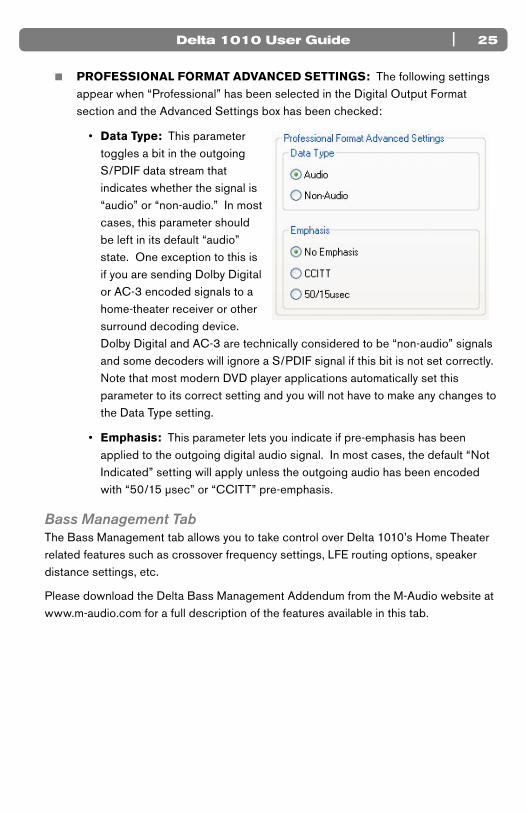
< PROFESSIONAL FORMAT ADVANCED SETTINGS: The following settings appear when “Professional” has been selected in the Digital Output Format section and the Advanced Settings box has been checked:
• Data Type: This parameter toggles a bit in the outgoing S/PDIF data stream that indicates whether the signal is “audio” or “non-audio.” In most cases, this parameter should be left in its default “audio” state. One exception to this is if you are sending Dolby Digital or AC-3 encoded signals to a home-theater receiver or other surround decoding device. Dolby Digital and AC-3 are technically considered to be “non-audio” signals and some decoders will ignore a S/PDIF signal if this bit is not set correctly. Note that most modern DVD player applications automatically set this parameter to its correct setting and you will not have to make any changes to the Data Type setting.
• Emphasis: This parameter lets you indicate if pre-emphasis has been applied to the outgoing digital audio signal. In most cases, the default “Not Indicated” setting will apply unless the outgoing audio has been encoded with “50/15 µsec” or “CCITT” pre-emphasis.
Bass Management TabThe Bass Management tab allows you to take control over Delta 1010’s Home Theater related features such as crossover frequency settings, LFE routing options, speaker distance settings, etc.
Please download the Delta Bass Management Addendum from the M-Audio website at www.m-audio.com for a full description of the features available in this tab.
Delta 1010 User Guide26 |
About Tab
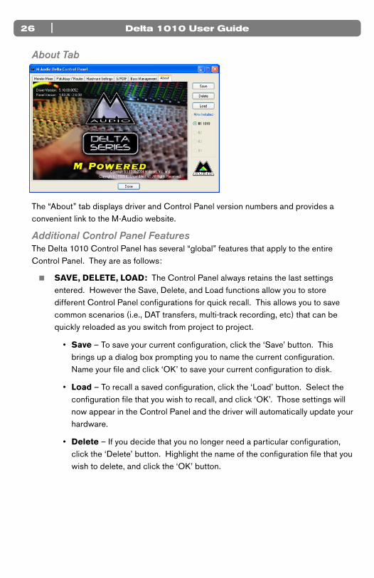
The “About” tab displays driver and Control Panel version numbers and provides a convenient link to the M-Audio website.
Additional Control Panel FeaturesThe Delta 1010 Control Panel has several “global” features that apply to the entire Control Panel. They are as follows:
< SAVE, DELETE, LOAD: The Control Panel always retains the last settings entered. However the Save, Delete, and Load functions allow you to store different Control Panel configurations for quick recall. This allows you to save common scenarios (i.e., DAT transfers, multi-track recording, etc) that can be quickly reloaded as you switch from project to project.
• Save – To save your current configuration, click the ‘Save’ button. This brings up a dialog box prompting you to name the current configuration. Name your file and click ‘OK’ to save your current configuration to disk.
• Load – To recall a saved configuration, click the ‘Load’ button. Select the configuration file that you wish to recall, and click ‘OK’. Those settings will now appear in the Control Panel and the driver will automatically update your hardware.
• Delete – If you decide that you no longer need a particular configuration, click the ‘Delete’ button. Highlight the name of the configuration file that you wish to delete, and click the ‘OK’ button.

| 27Delta 1010 User Guide
< H/W INSTALLED: Up to four Delta 1010 PCI Host Adapter cards may be installed in a PC at one time. This section displays all installed Delta cards, and allows you to select which card’s settings you would like to edit with the Control Panel software. To select a card for configuration, click its corresponding radio button in the “H/W Installed” list. Note that if you have installed multiple Delta cards in one system, you must synchronize the cards. To learn more about this, refer to the MultiTrack Driver Devices description on the Hardware Settings Tab section of this chapter. For additional information about multi-card operation, see the Digital Synchronization and Multi-Device Setup Guide found on www.m-audio.com.
Control Panel Software for Mac OS X
10D elta 1010 is a powerful audio interface with a variety of options and parameters
relating to its operation. After installing the Delta 1010 drivers, you can use the Control Panel software to configure the various parameters of the interface. Since the appearance and functionality of the Control Panel varies slightly between Windows XP and Mac OS X, each operating system is covered separately.
This section covers the Control Panel for Mac OS X users. Windows XP users should read the previous section of this User Guide to learn about the Windows XP Control Panel.
The Mac OS X Control Panel can be accessed by double-clicking the M-Audio icon in the Applications folder or by selecting the M-Audio Delta icon in System Preferences > Other. Your audio software may also allow you to access the Control Panel from within the application itself.
Monitor Mixer Tab
In order to hear your Monitor Mix, you first need to route the Monitor Mixer’s output signal to Delta 1010’s analog outputs 1/2 or to its S/PDIF output. This is done by selecting “Monitor Mixer” from the Analog Out 1/2 or S/PDIF Out column in the Patch Bay tab.

Delta 1010 User Guide28 |
Monitor Mixer is the first tab that appears when the Control Panel is opened.
This tab controls the digital mixer built into the Delta 1010 PCI Host Adapter card and has the following controls and indicators:< LEVEL FADERS: Each volume fader is controlled by dragging the vertical
slider with your mouse, or by clicking on the small up and down arrows above the faders (these “fine adjustment” arrows will raise or lower a fader in 0.5dB increments). The current fader setting is displayed numerically above each fader.
Note that the Monitor Mixer has no gain and that its faders only attenuate (reduce) incoming signal levels once the signals have been converted to digital audio. The highest setting is 0dB (or ‘Unity Gain’) and allows signals to pass through unaffected. The default fader setting (-144dB) is the quietest setting and will essentially mute the channel.
< VU METERS: Each channel features a VU meter that indicates audio levels in “dB relative to full-scale.” This means that the loudest possible signal is referred to as “0dB” and a signal that is, for example, 12dB lower than the maximum loudness is referred to as “-12dB.”
The meters are color-coded into three sections: green, yellow and red. The green section represents the “safe” zone and ranges from approximately -48dB to -12dB. The yellow section ranges from -12dB to -3dB, and the red section ranges from -3dB to 0dB. Once a signal reaches (or exceeds) 0dB, it means the signal is overloading Delta 1010’s analog-to-digital or digital-to-analog converters and is “clipping” or distorting. Unlike the analog distortion found on guitar amplifiers and effects pedals, digital distortion is harsh, unmusical, and should generally be avoided.
Therefore, we recommend setting input and output levels so that the loudest peaks of your incoming signal will reach the top of the yellow range but will
| 29Delta 1010 User Guide
generally not enter into the red zone. Technically, your signal may enter into the red zone without resulting in distortion but this not generally recommended since it leaves very little headroom. In other words, one loud note during a performance or mix may result in a severely distorted recording or mix.
< MASTER VOLUME: The Master Volume section is found to the left of the Mixer Input section. These meters control the overall output level of the Monitor Mixer. The adjacent VU meters indicate the Monitor Mixer’s output levels and are “post-fader.” This means changes to the master fader will affect the levels displayed on the VU meters.
< MIXER INPUTS: The Mixer Input channels are found to the right of the Master Volume section. These channels receive audio directly from Delta 1010’s analog and digital inputs as well as from the outputs of your audio software. This allows you to mix your incoming signals with your previously recorded tracks to create a hardware monitor mix that is virtually free of the delay (or “latency”) that is inherent in all software-based digital mixing systems.
NOTE: The VU meters in the Mixer Input section are “pre-fader.” This means that the meters display the incoming signal before the signal passes through the faders. Since the VU meters are pre-fader, making adjustments to a fader will have no impact on the levels displayed on its corresponding meter. The input meters have been set up in this way so that you will always see the “true” incoming signal levels. This helps you set optimum output levels on devices that are connected to Delta 1010, regardless of how the faders may be set up in the Monitor Mixer.
Because of the large number of mixer inputs, not all inputs are displayed simultaneously. The scroll bar at the bottom of the Mixer Input section allows you to scroll through the various inputs.
The inputs are labeled (from left to right): “Software Out 1/2” through “Software Out 7/8,” then “SW Out S/PDIF.” These inputs accept the digital audio streams being sent from your software application to the driver devices with those same names. Each name begins with “Software Out” to remind you that these are software streams and may not necessarily be routed to any physical outputs (see Patch Bay Page).
Further to the right are more channels, labeled “S/PDIF In” and “Analog In 1/2” through “Analog In 7/8.” These mixer inputs are audio streams from the physical Delta 1010 hardware inputs.
< PAN: Each mixer input may be individually panned from left to right using the horizontal slider beneath the channel’s volume fader.

Delta 1010 User Guide30 |
< SOLO: Each mixer input channel features a “Solo” checkbox. When a channel’s Solo box is checked, all other channels will be temporarily muted and only the “soloed” channel will be heard. Deactivating all solo boxes will return all input channels to their previous mute/unmute states.
Note that it is possible to solo more than one channel at a time on the Monitor Mixer. If more than one channel is soloed, all solo channels will be heard while all un-soloed channels will be muted and grayed out. To return to normal operation, uncheck all Solo boxes.
< MUTE: Every Monitor Mixer channel has a “Mute” checkbox. When this box is checked, its associated channel will not be routed to the stereo output and will not be heard in the monitor mix. When the box is unchecked, its associated channel will be routed to the mixer’s output.
< STEREO LINK: All of the Monitor Mixer’s channel pairs have a “Stereo Link” checkbox. When this box is checked, the left/right faders move together so that the channels may be adjusted as a stereo pair. When this box is unchecked, the faders can be adjusted independently.
Patch Bay Tab
Each column in the Patch Bay tab represents a physical output pair on your Delta 1010 interface. The radio buttons in each column allow you to select the audio source for that physical ouput.
To use the Patch Bay, first locate the Delta 1010 output that you’d like to use—the outputs are listed across the top of the tab. Analog Out 1/2, 3/4, 5/6, and 7/8 correspond to analog outputs 1-8 while S/PDIF Out corresponds to the S/PDIF output.
Next, click the radio button for the input source you’d like to connect to your chosen output. The available options listed in the column below each output. Delta 1010 will now route that audio source to your selected output.

| 31Delta 1010 User Guide
The input sources are described below:
• Software Out 1/2 through 7/8: These inputs correspond to the outputs of your audio software.
• Monitor Mixer: This input corresponds to the output of the Delta 1010 Monitor Mixer. This audio source can only be routed to analog outputs 1-2 and/or the S/PDIF output.
• S/PDIF In: This input corresponds to the S/PDIF input.
• S/PDIF In Rev.: This corresponds to the S/PDIF input but swaps the left and right channels.
• Analog In 1/2 through 7/8: These inputs correspond to the hardware analog inputs of the Delta 1010 interface.
TIP: To restore the Router/Patchbay to its default settings, select the topmost radio button in each column.
Hardware Settings Tab
The Hardware Settings tab gives you control over a variety of features of Delta 1010. These features are grouped into the following sections:
NOTE: Some audio applications may make certain Control Panel settings unavailable while the application is open. In this case, you will need to adjust these settings through the audio application itself. This process varies from program to program, but it is usually done through the application’s “Configuration” or “Audio Settings” menu. Refer to your audio software’s documentation to learn how to do this.
Delta 1010 User Guide32 |
< SAMPLE RATE: This drop-down menu selects the sampling rate of the interface and determines the rate at which all of the digital components of Delta 1010 (A/D and D/A converters, digital Monitor Mixer, etc.) will operate. This section also includes the following checkbox:
• Locked: The “Locked” checkbox allows you to force Delta 1010 to operate at the chosen sample rate. This will prohibit audio applications from attempting to operate Delta 1010 at a sample rate other than the one selected in the Control Panel.
By default, this box is left unchecked and allows your audio software to choose any sample rate that is supported by the Delta 1010 hardware.
NOTE: Certain sample rate options are “grayed out” because Delta 1010 does not support these rates.
< CLOCK SOURCE: This section allows you to select the source of the interface’s master clock. Delta 1010 allows you to select among the following three sources: Internal Crystal, S/PDIF Input, and Word Clock.
If you have connected a S/PDIF device to your Delta 1010’s S/PDIF input, set S/PDIF Input as the source of Delta 1010’s master clock and make sure that the external S/PDIF device is configured to provide the master clock signal. This will slave Delta 1010 to the external device’s clock and allow S/PDIF signals to enter the interface.
If you have connected a Word Clock device to your Delta 1010 and would like to use that device’s clock as the master clock source, select Word Clock as the source of Delta 1010’s master clock. This will slave Delta 1010 to the external word clock device’s clock.
NOTE: It is possible to synchronize Delta 1010 through its Word Clock input while simultaneously receiving signals at the S/PDIF input. However, all connected digital input devices need to be synchronized to the same clock source before the digital signals enter the Delta 1010 interface.
Next to the Clock Source drop-down menu is an indicator that displays the current clocking status of the interface. The word “Locked” appears when the interface is locked to an external clock and “Waiting” appears when Delta 1010 is not receiving a valid clock signal. Nothing appears if “Internal Crystal” setting is selected since the interface is locked to its own internal clock.
For more information about Clocking, please see Appendix A: Clocking at the end of this guide and/or read the Digital Sync and Multi-Device Setup Guide found on www.m-audio.com.
| 33Delta 1010 User Guide
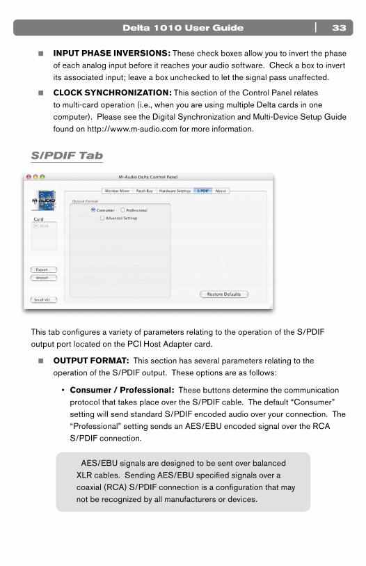
< INPUT PHASE INVERSIONS: These check boxes allow you to invert the phase of each analog input before it reaches your audio software. Check a box to invert its associated input; leave a box unchecked to let the signal pass unaffected.
< CLOCK SYNCHRONIZATION: This section of the Control Panel relates to multi-card operation (i.e., when you are using multiple Delta cards in one computer). Please see the Digital Synchronization and Multi-Device Setup Guide found on http://www.m-audio.com for more information.
S/PDIF Tab
This tab configures a variety of parameters relating to the operation of the S/PDIF output port located on the PCI Host Adapter card.
< OUTPUT FORMAT: This section has several parameters relating to the operation of the S/PDIF output. These options are as follows:
• Consumer / Professional: These buttons determine the communication protocol that takes place over the S/PDIF cable. The default “Consumer” setting will send standard S/PDIF encoded audio over your connection. The “Professional” setting sends an AES/EBU encoded signal over the RCA S/PDIF connection.
AES/EBU signals are designed to be sent over balanced XLR cables. Sending AES/EBU specified signals over a coaxial (RCA) S/PDIF connection is a configuration that may not be recognized by all manufacturers or devices.
Delta 1010 User Guide34 |
• Advanced Settings: Selecting this check box reveals several advanced features at the bottom of the S/PDIF tab. Note that your selection of “Consumer” or “Professional” (see above) will determine the advanced options that will be displayed when this box is checked.
• Restore Defaults: This button will restore all of the advanced output settings to their factory default settings.
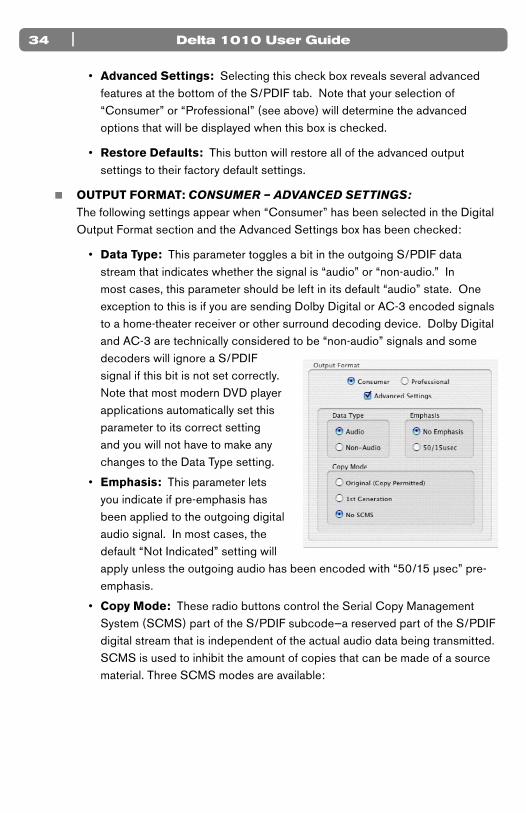
< OUTPUT FORMAT: CONSUMER – ADVANCED SETTINGS: The following settings appear when “Consumer” has been selected in the Digital Output Format section and the Advanced Settings box has been checked:
• Data Type: This parameter toggles a bit in the outgoing S/PDIF data stream that indicates whether the signal is “audio” or “non-audio.” In most cases, this parameter should be left in its default “audio” state. One exception to this is if you are sending Dolby Digital or AC-3 encoded signals to a home-theater receiver or other surround decoding device. Dolby Digital and AC-3 are technically considered to be “non-audio” signals and some decoders will ignore a S/PDIF signal if this bit is not set correctly. Note that most modern DVD player applications automatically set this parameter to its correct setting and you will not have to make any changes to the Data Type setting.
• Emphasis: This parameter lets you indicate if pre-emphasis has been applied to the outgoing digital audio signal. In most cases, the default “Not Indicated” setting will apply unless the outgoing audio has been encoded with “50/15 µsec” pre-emphasis.
• Copy Mode: These radio buttons control the Serial Copy Management System (SCMS) part of the S/PDIF subcode—a reserved part of the S/PDIF digital stream that is independent of the actual audio data being transmitted. SCMS is used to inhibit the amount of copies that can be made of a source material. Three SCMS modes are available:
| 35Delta 1010 User Guide
Original (Copy Permitted) – This setting indicates that the audio stream currently playing is a “master” recording and that the source material may be copied by a recording device.
1st Generation – This setting indicates that the source material is a first generation copy of the master recording. Most recording devices will reject material with this SCMS setting.
No SCMS – This setting does not apply any SCMS restrictions to the outgoing audio stream. This allows an external recording device to make a copy of the outgoing audio data.
NOTE: Some manufacturers’ products may interpret these codes differently and may require you to experiment with the settings until proper operation is achieved.
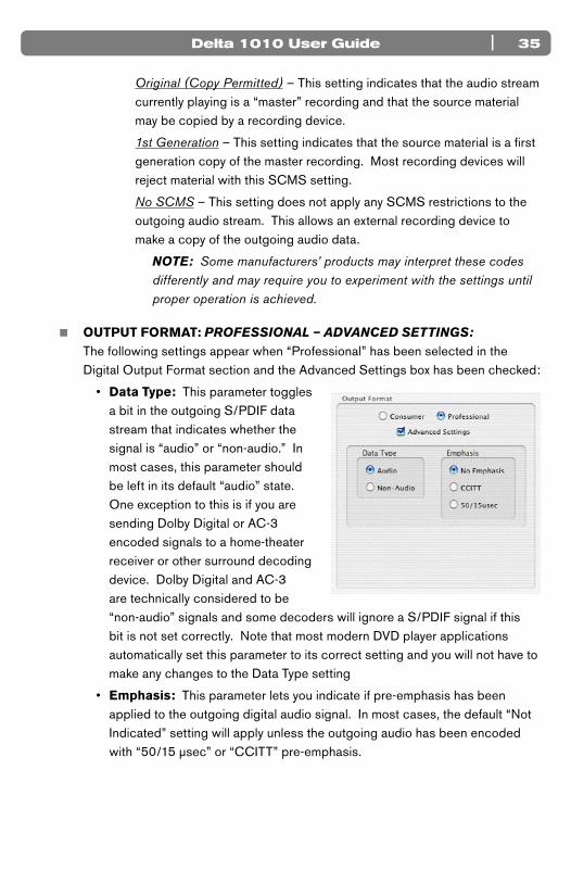
< OUTPUT FORMAT: PROFESSIONAL – ADVANCED SETTINGS: The following settings appear when “Professional” has been selected in the Digital Output Format section and the Advanced Settings box has been checked:
• Data Type: This parameter toggles a bit in the outgoing S/PDIF data stream that indicates whether the signal is “audio” or “non-audio.” In most cases, this parameter should be left in its default “audio” state. One exception to this is if you are sending Dolby Digital or AC-3 encoded signals to a home-theater receiver or other surround decoding device. Dolby Digital and AC-3 are technically considered to be “non-audio” signals and some decoders will ignore a S/PDIF signal if this bit is not set correctly. Note that most modern DVD player applications automatically set this parameter to its correct setting and you will not have to make any changes to the Data Type setting
• Emphasis: This parameter lets you indicate if pre-emphasis has been applied to the outgoing digital audio signal. In most cases, the default “Not Indicated” setting will apply unless the outgoing audio has been encoded with “50/15 µsec” or “CCITT” pre-emphasis.

Delta 1010 User Guide36 |
About Tab
The “About” tab displays driver and Control Panel version numbers.
Additional Control Panel Features
The Delta 1010 Control Panel has several “global” features that apply to the entire Control Panel. They are as follows:
< EXPORT, IMPORT: The Macintosh OS X Control Panel will retain the last settings entered. If you would like to store different Control Panel configurations on your hard drive for quick recall, you may do so using the “Export” and “Import” buttons:
• Export – To save a Control Panel configuration, click the “Export” button. A window will appear prompting you to select a name and location for the current configuration. Once you have done so, click the “Save” button.
• Import – To import a previously saved Control Panel configuration, click the “Import” button. A window will appear prompting you to select the configuration file you would like to load. Once you have selected your file, click the “Open” button.
< CARD: Up to four Delta 1010 PCI Host Adapter cards may be installed in a Macintosh at one time, however, this may be restricted by the number of PCI slots available in your Macintosh. This section displays all installed Delta cards, and allows you to select which card’s settings you would like to edit with the Control Panel software. To select a card for configuration, click its corresponding radio button in the “Card” list. Note that if you have installed multiple Delta cards in one system, you must synchronize the cards. To learn more about this, refer to the Clock Synchronization description in the Hardware Settings Tab section of this chapter and/or read the Digital Synchronization and Multi-Device Setup Guide found on www.m-audio.com.

| 37Delta 1010 User Guide
< SMALL VU: Clicking this button will display all of the Control Panel’s VU meters in a miniature screen. This screen is intended to help recording engineers by displaying all input and output levels at a quick glance. Note that this window does not have any controls; it is for display purposes only. To return to the regular Control Panel, click the “Show Panel” button.

Delta 1010 User Guide38 |
Troubleshooting
11Problem: No sound.
Possible Cause 1: Improper connection to external devices. Verify that the analog outputs of Delta 1010 are properly connected to the inputs of an appropriate device (such as a mixer, amplifier, or powered monitors) using quality cables. If you are connecting digitally to a digital device such as a DAT recorder or digital mixer, make sure you are using proper digital cables and that the device is configured to receive signals from Delta 1010.
Possible Cause 2: The Delta 1010 device drivers are not properly installed. See the installation instructions in the printed Delta 1010 Quick Start Guide for further information.
Possible Cause 3: There is a resource conflict between Delta 1010 and another device in your computer. Try the following to see if the issue resolves:
a. Move the PCI Host Adapter card to a different PCI slot.
b. Remove other PCI cards from your system one at a time to see if the resource conflict can be traced to specific PCI slot or card in your system.
c. If your computer includes a built-in sound card, turn it off. This is usually done through the system BIOS or by changing a hardware jumper on the motherboard. See your computer’s documentation for more information about this.
If these steps do not resolve your problems, please see the Support > Knowledge Base page on www.m-audio.com for additional information.
Possible Cause 4: If the rack-mount box is connected to the PCI Host Adapter Card and your computer is powered on, but the Power LED is not illuminated, shut down your computer and double-check that the host cable is connected properly.
| 39Delta 1010 User Guide
Possible Cause 5: If you see visual activity on the Monitor Mixer’s VU meters, but your audio application’s input meters are not moving, then Delta 1010’s Patchbay/Router and/or your audio application may not be configured properly.
• Refer to the Patchbay/Router Tab section of this User Guide to learn more about how to configure Delta 1010’s Patchbay/Router.
• Refer to your software’s documentation to learn how to use Delta 1010 as its audio input/output device.
Possible Cause 6: Your audio outputs have been misrouted in the Control Panel. Check the Control Panel’s Patchbay/Router tab to verify the output routing assignments. Also, if you are monitoring the outputs of Delta 1010’s Monitor Mixer, make sure that the mixer’s faders, solo, and mute controls are set properly.
Problem: No visual activity on audio input VU meters of your audio software.
Possible Cause 1: Your software is not configured to use Delta 1010 as its audio interface. Make sure that Delta 1010 drivers are properly installed and verify that the audio application is configured to use Delta 1010. See your software’s documentation to learn how to do this.
Possible Cause 2: If your audio software is recording the output of the Delta 1010 Monitor Mixer, be sure that the mixer’s faders, solo and mute controls are set properly.
Possible Cause 3: Poor quality cabling. Verify that your audio cables are plugged in properly and are in good working order.
Problem: Repetitious (looping) Sound.
Possible Cause: An IRQ resource conflict. Often this will result in a small segment of sound (0.5 to 1 second) repeating itself endlessly, sometimes causing the computer to lock up. See the “No sound” troubleshooting section at the beginning of this section for tips on how to resolve system resource conflicts.
Delta 1010 User Guide40 |
Problem: Clicks, pops, and other glitches in audio streams.
Possible Cause 1: Input levels are too loud and are resulting in clipping or distortion. Lower the source’s output level. If you are using a microphone preamplifier, reduce its gain to avoid overloading the interface. The meter display in the Control Panel can be used as a visual aid to help you set optimal input levels.
Note that the faders of the Monitor Mixer only affect the monitor mix and do not have any effect on the signal being recorded into your audio application.
Possible Cause 2: The Delta 1010 audio buffer size is set too low and must be increased. Each audio application handles buffer settings differently, but the options for changing buffer sizes are usually found under the program’s “setup” or “audio preferences” menus. Refer to your audio application’s documentation to learn how to increase buffer size.
TIP: Some audio applications require you to run a soundcard calibration routine (sometimes called “profiling”) the first time you use the software with a new audio card. This routine should automatically determine the optimum buffer size setting. If your computer’s hardware or software configuration has recently changed, try running the profiling routine again to see if this resolves the issue.
Possible Cause 3: If you have connected your Delta 1010 to other digital devices using S/PDIF or Word Clock connections, ensure that your clock sources have been configured properly. See the section entitled “Synchronization” earlier in this guide to learn more about this topic
Possible Cause 4: By default, Windows XP features a variety of graphical effects that improve the appearance of the operating system. These effects may adversely affect performance on older systems. Try turning off these visual effects to see if audio issues are resolved. In Windows XP, go to Start > Settings > Control Panel > System. Select the Advanced tab and click the “Setting” button under Performance. Select “Adjust for best performance” from the window that appears.
Possible Cause 5: Under Windows XP, some accelerated graphics cards use excessive amounts of system bandwidth, preventing the recording buffer of an audio card from keeping up with demand. This can cause clicks in the audio streams. Reducing or turning off the graphics card’s graphics acceleration feature often resolves this problem. In Windows XP, go to Start > Settings > Control Panel > Display. Select the Settings tab and click the Advanced button. Select the Troubleshoot tab and set the “Hardware acceleration” slider to “None.”

| 41Delta 1010 User Guide
Technical Specifications
12Analog Audio
Peak Analog Input Signal: +20.2dBu (+4dBu setting),
+2.1dBV (-10dBV setting)
Peak Analog Output Signal: +20.0dBu (+4dBu setting),
+2.0dBV (-10dBV setting)
Dynamic Range: Outputs: 114dB (a-weighted),
Inputs: 109dB (a-weighted)
THD (at 0dBFS): Outputs: less than 0.0015%,
Inputs: less than 0.001%
Frequency Response: 22Hz - 22kHz, -0.3,-0.2dB
Input Impedance: 10k ohms minimum
Input Connectors: 1/4” female, balanced or unbalanced
Output Connectors: 1/4” female, balanced or unbalanced
Digital Audio
Digital Input Format: S/PDIF coaxial, 0.5V to 5V peak-to-peak
Digital Input Sample Rate: 32kHz to 96kHz
Digital Output Format: S/PDIF coaxial, 0.5V peak-to-peak;
AES/EBU data stream over S/PDIF coaxial
Digital Output Sample Rate: 32kHz to 96kHz
Word Clock Input Rate: 32kHz to 50kHz
Word Clock Output Rate: 32kHz to 96kHz

Delta 1010 User Guide42 |
Technical Info
13Caution: Electro Static Discharge, Electrical Fast Transient and Conducted RF interference may cause the unit malfunctioning. In such case, unplug the unit and plug it in again to restore normal operation.
NOTE: Your M-Audio product has been tested to comply with FCC Standards FOR HOME OR OFFICE USE. Modifications not authorized by the manufacturer may void users authority to operate this device.
NOTE: This equipment has been tested and found to comply with the limits for a Class B digital device, pursuant to Part 15 of the FCC Rules. These limits are designed to provide reasonable protection against harmful interference in a residential installation. This equipment generates, uses and can radiate radio frequency energy and, if not installed and used in accordance with the instructions, may cause harmful interference to radio communications. However, there is no guarantee that interference will not occur in a particular installation. If this equipment does cause harmful interference to radio or television reception, which can be determined by turning the equipment off and on, the user is encouraged to try to correct the interference by one or more of the following measures:
< Re-orient or relocate the receiving antenna.
< Increase the separation between the equipment and receiver.
< Connect the equipment to an outlet on a circuit different from that to which the
receiver is connected.
< Consult the dealer or an experienced radio/ TV technician for help.
ASIO is a trademark of Steinberg Soft– und Hardware GmbH.
VST is a trademark of Steinberg Soft– und Hardware GmbH
WARNING: This product contains chemicals, including lead, known to the State of California to cause cancer, and birth defects or other reproductive harm. Wash hands after handling.
Delta 1010
Tested to comply withFCC standards
FOR HOME OR STUDIO USE
| 43Delta 1010 User Guide
Appendix
14Appendix A: Clocking
For proper operation, all digital audio systems (including the Delta 1010 interface) must be synchronized to a single master clock. If your digital audio systems are not configured in this way, you will hear clicks, pops, and other glitches in your audio streams.
If you are using Delta 1010 in conjunction with other digital devices in your studio, you will need to designate one device in your studio as the “clock master.” All other digital devices must be set to lock (or “slave”) to the master device’s clock.
For example, if you have connected your Delta 1010 to a DAT recorder using a S/PDIF cable, you must configure either Delta 1010 or the DAT recorder to act as the clock master, while the other device must be set to “slave” mode. If your devices are not configured in this way, you will hear clicks, pops, and other unwanted glitches in your audio.
If you wish to set Delta 1010 as the master, go to the Hardware Settings tab in the Control Panel and set the “Clock Source” parameter to “Internal Xtal” (“Internal Crystal” for Mac OS X users). If you would like Delta 1010 to slave to another device connected using S/PDIF or Word Clock, select “S/PDIF” or “Word Clock” under the Master Clock section. If you’ve set Delta 1010 to slave to an external clock, you’ll need to ensure that the external device is set as the clock master. Refer to your device’s documentation to learn how to do this.
TIP: If you are only using the analog I/O of Delta 1010 and do not plan to use its S/PDIF or Word Clock connectors, set the “Clock Source” parameter to “Internal Xtal” (“Internal Crystal” for Mac OS X users).
NOTE: If you are using multiple Delta cards in the same system, please also see the Digital Synchronization and Multi-Device Setup Guide found on www.m-audio.com.
Delta 1010 User Guide44 |
Warranty Terms and Registration
15Warranty Terms
M-Audio warrants products to be free from defects in materials and workmanship, under normal use and provided that the product is owned by the original, registered user. Visit www.m-audio.com/warranty for terms and limitations applying to your specific product.
Warranty Registration
Immediately registering your new M-Audio product entitles you to full warranty coverage and helps M-Audio develop and manufacture the finest quality products available. Register online at www.m-audio.com/register to receive FREE product updates and for the chance to win M-Audio giveaways.
© 2007 Avid Technology, Inc. All rights reserved. Product features, specifications, system requirements and availability are subject to change without notice. Avid, M-Audio, Delta 1010 and Tampa are either trademarks or registered trademarks of Avid Technology, Inc. All other trademarks contained herein are the property of their respective owners.
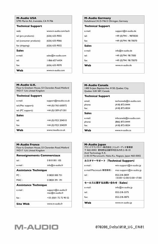
M-Audio USA5795 Martin Rd., Irwindale, CA 91706
Technical Support
web: www.m-audio.com/tech
tel (pro products): (626) 633-9055
tel (consumer products): (626) 633-9066
fax (shipping): (626) 633-9032
Sales
e-mail: [email protected]
tel: 1-866-657-6434
fax: (626) 633-9070
Web www.m-audio.com
M-Audio U.K.Floor 6, Gresham House, 53 Clarenden Road, WatfordWD17 1LA, United Kingdom
Technical Support
e-mail: [email protected]
tel:(Mac support): +44 (0)1765 650072
tel: (PC support): +44 (0)1309 671301
Sales
tel: +44 (0)1923 204010
fax: +44 (0)1923 204039
Web www.maudio.co.uk
M-Audio FranceFloor 6, Gresham House, 53 Clarenden Road, WatfordWD17 1LA, United Kingdom
Renseignements Commerciaux
tel : 0 810 001 105
e-mail : [email protected]
Assistance Technique
PC : 0 0820 000 731
MAC : 0 0820 391 191
Assistance Technique
e-mail : [email protected]@m-audio.fr
fax : +33 (0)01 72 72 90 52
Site Web www.m-audio.fr
M-Audio GermanyKuhallmand 34, D-74613 Ohringen, Germany
Technical Support
e-mail: [email protected]
tel: +49 (0)7941 - 9870030
fax: +49 (0)7941 98 70070
Sales
e-mail: [email protected]
tel: +49 (0)7941 98 7000
fax: +49 (0)7941 98 70070
Web www.m-audio.de
M-Audio Canada1400 St-Jean Baptiste Ave. #150, Quebec City, Quebec G2E 5B7, Canada
Technical Support
email:
phone:
fax:
(418) 872-0444
(418) 872-0034
Sales
e-mail:
phone:
fax:
(866) 872-0444
(418) 872-0034
Web www.m-audio.ca
M-Audio Japanアビッドテクノロジー株式会社 |エムオーディオ事業部〒 460-0002 愛知県名古屋市中区丸の内 2-18-10Avid Technology K.K.2-18-10 Marunouchi, Naka-Ku, Nagoya, Japan 460-0002
カスタマーサポート(Technical Support)
e-mail : [email protected]
e-mail(Macintosh環境専用): [email protected]
tel : 052-218-0859(10:00~12:00/13:00~17:00)
セールスに関するお問い合わせ(Sales)
e-mail: [email protected]
tel: 052-218-3375
fax: 052-218-0875
Web www.m-audio.jp