deployment guide: a multi-product security … guide: a multi-product security architecture example...
TRANSCRIPT

Deployment Guide: A Multi-Product Security Architecture Example

Deployment Guide: A Multi-Product Security Architecture Example Gigamon Inc.
P a g e 2 | 42 +
COPYRIGHT Copyright © 2017 Gigamon. All Rights Reserved. No part of this publication may be reproduced, transmitted, transcribed, stored in a retrieval system, or translated into any language in any form or by any means without Gigamon’s written permission.
TRADEMARK ATTRIBUTIONS Copyright © 2017 Gigamon. All rights reserved. Gigamon and the Gigamon logo are trademarks of Gigamon in the United States and/or other countries. Gigamon trademarks can be found at www.gigamon.com/legal- trademarks. All other trademarks are the trademarks of their respective owners.

Deployment Guide: A Multi-Product Security Architecture Example Gigamon Inc.
P a g e 3 | 42 +
Table of Contents
INTRODUCTION .................................................................................................................................4
OVERVIEW .........................................................................................................................................5 DEPLOYMENT PREREQUISITES.......................................................................................................................... 6 ARCHITECTURE OVERVIEW .............................................................................................................................. 7
NETWORK TOPOLOGY ........................................................................................................................8
CONFIGURATION ...............................................................................................................................9 CONFIGURING FIREEYE NX 2400 FOR INLINE BLOCK OPERATION MODE .............................................................. 10
Configuring FireEye Actions Taken: Comfort Page, TCP Resets: ........................................................ 11 CONFIGURING PALO ALTO PA 3020 FOR VIRTUAL WIRE MODE ......................................................................... 12 CONFIGURING CISCO FIREPOWER NGIPSV .................................................................................................... 14 CONFIGURING SPLUNK ENTERPRISE ................................................................................................................ 19 CONFIGURING GIGAVUE-HC2 ...................................................................................................................... 22
Configuring the Inline Network .......................................................................................................... 22 Configuring the Inline Tools ................................................................................................................ 24 Configuring the Inline Tool Groups ..................................................................................................... 26 Configuring the Inline Serial Tools ...................................................................................................... 28 Configuring the Inline Traffic Flow Maps ........................................................................................... 30
CONFIGURING IPFIX TO SEND METADATA TO SPLUNK ENTERPRISE ...................................................................... 32
OTHER GIGAMON FEATURES ............................................................................................................ 38
SUMMARY ....................................................................................................................................... 40

Deployment Guide: A Multi-Product Security Architecture Example Gigamon Inc.
P a g e 4 | 42 +
Introduction
Today’s enterprises have many choices to make when it comes to securing their IT infrastructure. Hundreds of vendors are offering a wide variety of security solutions – each with their own strengths (and weaknesses). Do you deploy a suite of functionality from one of the large vendors, select the best-of-breed for each tool type you require, or design a mix of the two? Most enterprises will start with a Next Generation Firewall (NGFW) but what should come next: a Security Information and Event Manager (SIEM), a secure email gateway, or Network Access Control (NAC)? The answer can be different for each enterprise based on risk assessment, budget, business profile, technologies deployed, and the opinions of architects and trusted advisors.
With this deployment guide, we describe how a leading set of security tools can be effectively deployed using the Gigamon Visibility Platform. It is not designed to be the prescribed InfoSec architecture for your business. It is just an architectural example to help you understand some of the options available to you and to demonstrate the flexibility and benefits such an architectural approach can provide.
While each of the vendor products included are leaders for the functionality we have described, they are not the only choice open to you. Several of the products have over-lapping functionality – for example, most of the vendors provide threat intelligence feeds and you probably wouldn’t choose to subscribe to all the available services. Some of this overlap is desirable – different technological approaches may be suited to discovering various types of threats, i.e. zero-day – while single choices for other functionality may be desirable. We recommend consulting security experts within your organization or a consultant at your chosen VAR when designing the best solution for you.
In our example architecture, we have described how to deploy the following Technology Partner devices:
Advanced Malware Detection/Sandbox: FireEye NX
Next Generation Firewall with Application Visibility and Simple Category Blocking: Palo Alto Networks PA-3020 Series
Intrusion Prevention System (IPS): Cisco FirePOWER
Security Information and Event Manager (SIEM): Splunk Enterprise
Packet Capture Device: FireEye PX
The approach we have described can be deployed all at once, or over time – it’s up to you to balance the budget, business disruption and risk in deciding how to define your project. By utilizing Gigamon’s Visibility Platform as the underlying method for obtaining access to any data traversing the managed infrastructure, you will build an effective and resilient foundation that is easily extensible to support current and future security requirements.

Deployment Guide: A Multi-Product Security Architecture Example Gigamon Inc.
P a g e 5 | 42 +
Overview
Gigamon, along with its ecosystem partners, solves customer problems with best of breed monitoring solutions for network security, troubleshooting, application monitoring, forensic analysis, and more. Technology Partners attach their solutions to the Gigamon Visibility Platform to get unobstructed, on demand access to any or all segments of the physical and virtual network.
The Gigamon Visibility Platform enables a modern network infrastructure that delivers pervasive visibility into all the data in motion across your entire network – whether physical, virtual or cloud. This visibility solution allows enterprises, governments, and service providers to effectively manage, secure, and understand what’s happening across their increasingly complex networks.
For Security Operations (SecOps) teams, Gigamon helps you see more so you can secure more. Our visibility platform provides capabilities that enable and enhance your security tools by optimizing nework data and delivering the appropriate data to the proper security tools.
This deployment guide describes an example of a joint solution with FireEye NX, Cisco FirePOWER NGIPS, Palo Alto Networks NGFW, and Splunk Enterprise all connected to the Gigamon Visibility Platform.
As organization’s scaling requirements change with the addition or upgrade of network links, Gigamon provides a flexible and efficient way to deploy inline and out-of-band tools without affecting traffic continuity or monitoring operations. The Gigamon platform provides all the necessary traffic handling capabilities to ensure that only packet data relevant to the function of each attached device gets sent to that device. It also helps avoid devices becoming overloaded with traffic that cannot be processed because it is irrelevant to the function being performed or because the device cannot process that volume of data.
Gigamon provides inline tool groups for partner appliances to deliver Security Service Assurance (SSA) for inline advanced malware protection. Putting FireEye, Cisco and Palo Alto Network’s security devices in the inline tool group helps ensure that they remain available even in the case of appliance maintenance or failure. Also, Gigamon’s GigaVUE HC Series Inline Bypass Modules provide physical bypass protection to provide continued network availability in the event of a power outage on the GigaVUE-HC2 nodes.
The solution described in this guide was tested with Gigamon GigaVUE-HC2, Palo Alto 3020 NGFWs, Cisco NGIPS, and FireEye NX 2400 Series advanced malware protection appliances in inline mode. The FireEye PX series and Splunk Enterprise are connected in out-of-band mode.
Deployment Guide: A Multi-Product Security Architecture Example Gigamon Inc.
P a g e 6 | 42 +
Deployment Prerequisites
The joint Gigamon solution consisting of Palo Alto NGFWs, Cisco NGIPSs, FireEye NX 2400s, FireEye PX series appliances, and Splunk Enterprise comprises of the following:
GigaVUE-FM version 3.5
GigaVUE-HC2 chassis with GigaVUE-OS 4.8 and GigaVUE HC Series GigaBPS module
Two Palo Alto 3020 NGFWs running the following:
• Software version: 7.1 or newer
Two Cisco NGIPS running the following:
• Software version: 6.0
Two FireEye NX2400 appliances running the following:
• Software version: 7.7.3
• Content version: 531.148
• Guest image information: WinXP SP3, Win7X64 SP1, Win7 SP1 – 15.1218
Standalone FireEye PX series
Standalone Splunk Enterprise server
• Software version: 6.5.0

Deployment Guide: A Multi-Product Security Architecture Example Gigamon Inc.
P a g e 7 | 42 +
Architecture Overview
This section discusses the joint solution using a Gigamon GigaVUE-HC2 with bypass module, two Palo Alto 3020 NGFWs, two Cisco NGIPSs, two FireEye NX 2400 appliances in inline mode along with an optional standalone FireEye PX series appliance and Splunk Enterprise in out-of-band mode. The reference architecture in Figure 1 shows each component’s position in the overall network infrastructure, where all network components and inline security tools are connected directly to the GigaVUE-HC2.
Figure 1: Gigamon Inline Bypass Joint Solution
For configuration purposes, the side where clients reside is assigned as side A. The side connected to the internet is assigned as side B.
NOTE: It is essential that the inline network and inline tool device bridge links are connected to GigaVUE-HC2 correctly relative to side A and side B so that traffic is distributed correctly to the devices in the inline tool group.
Two of each inline device type is chosen to demonstrate the additional resilience and scale that can be achieved this way. Gigamon’s GigaSTREAM traffic balancing solution means that traffic can be shared across the available devices. Additional capacity could be added by deploying additional devices as traffic levels grow.
Deployment Guide: A Multi-Product Security Architecture Example Gigamon Inc.
P a g e 8 | 42 +
Network Topology
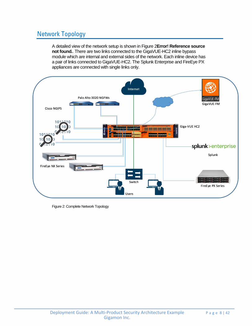
A detailed view of the network setup is shown in Figure 2Error! Reference source not found.. There are two links connected to the GigaVUE-HC2 inline bypass module which are internal and external sides of the network. Each inline device has a pair of links connected to GigaVUE-HC2. The Splunk Enterprise and FireEye PX appliances are connected with single links only.
Figure 2: Complete Network Topology

Deployment Guide: A Multi-Product Security Architecture Example Gigamon Inc.
P a g e 9 | 42 +
Configuration
This section describes the configuration procedures for the GigaVUE-HC2, Palo Alto PA-3020, FireEye NX 2400 and Cisco FirePOWER through the respective management platforms. The procedures are organized as follows:
Configuring FireEye NX 2400 for Inline Block Operation Mode
Configuring Palo Alto PA 3020 for Virtual Wire Mode
Configuring Cisco FirePOWER NGIPSv
Configuring Splunk Enterprise
Configuring GigaVUE-HC2
Deployment Guide: A Multi-Product Security Architecture Example Gigamon Inc.
P a g e 10 | 42 +
Configuring FireEye NX 2400 for Inline Block Operation Mode
The FireEye GUI procedures focus on FireEye inline block operational mode. The configuration procedures in the later section will configure the GigaVUE-HC2 to send live traffic to the FireEye inline tool group, which will allow the use of FireEye’s on-system deployment testing tools. Per FireEye’s best practices guidelines, GigaVUE-HC2 will be configured to distribute the traffic to the two FireEye appliances in the inline tool group, assuring all traffic for any given client (by IP address) goes to the same member of the FireEye inline tool group. This ensures complete session information is sent to a single device which, in turn, delivers best possible performance from your solution.
NOTE: This section assumes the FireEye appliances are directly connected to the GigaVUE-HC2 as shown in Figure 2. All GigaVUE-HC2 ports that FireEye appliances are connected to should be configured as port type Inline Tool. Furthermore, all GigaVUE-HC2 inline bypass ports that the network devices are connected to should be configured as Inline Network type ports. For specific instructions on how to complete these tasks, refer to the Help Topics in GigaVUE-FM.
To individually configure FireEye NX 2400 to block traffic so it detects malicious traffic, perform the following steps for each FireEye appliance:
1. On the FireEye GUI, select Settings > Interfaces - Operational Modes.
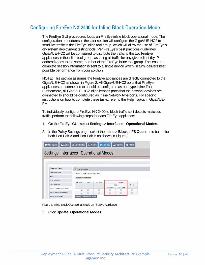
2. In the Policy Settings page, select the Inline > Block > FS Open radio button for both Port Pair A and Port Pair B as shown in Figure 3.
Figure 3: Inline Block Operational Mode on FireEye Appliance
3. Click Update: Operational Modes.

Deployment Guide: A Multi-Product Security Architecture Example Gigamon Inc.
P a g e 11 | 42 +
Configuring FireEye Actions Taken: Comfort Page, TCP Resets:
FireEye NX has several options for actions to be taken when malicious content is detected. The following procedure walks you through the steps for sending a customized comfort page to the client and TCP resets to client and server. These steps are optional.
To set the Actions Taken and Comfort Page, perform the following steps:
1. In the Policy Settings > Actions Taken section, select all check boxes for Comfort page and TCP resets for both Port Pair A and Port Pair B as shown in Figure 4.
Figure 4: FireEye Action Taken/Comfort Page Customization
2. In the Comfort Page section, leave the radio button set to access-denied (HTTP response code 401), unless you have a preference for access-forbidden (HTTP response code 403).
3. In the Comfort Page Message box, type a customized message for Port Pair A and Port Pair B.
4. Click Update: Action Taken / Comfort Page.

Deployment Guide: A Multi-Product Security Architecture Example Gigamon Inc.
P a g e 12 | 42 +
Configuring Palo Alto PA 3020 for Virtual Wire Mode
To configure the Palo Alto 3020 NGFW for Virtual Wire mode, perform the following steps for each Palo Alto appliance. You can skip these steps if the Virtual Wires you wish to use are already configured.
1. In the Palo Alto management GUI, select the Network tab and do the following:
a. Click on the first interface you want to configure as part of the pair.
b. Click the Interface Type drop-down list and select Virtual Wire as the interface type as shown in Figure 5.
Figure 5: FireEye Ethernet Interface
2. On the Config tab, click the Virtual Wire drop-down list and select New > Virtual Wire as shown in Figure 6. The Virtual Wire dialog box is displayed.
Figure 6: FireEye Virtual Wire Configuration

Deployment Guide: A Multi-Product Security Architecture Example Gigamon Inc.
P a g e 13 | 42 +
3. In the Virtual Wire dialog box, enter a name for the Virtual Wire and click OK. In this example, the name entered is Virtual-Wire as shown in Figure 7.
Figure 7: FireEye Virtual Wire
4. In the Security Zone drop-down list, select untrust and click OK as shown in Figure 8.
Figure 8: FireEye Security Zone
5. Repeat steps 2 to 4 for configuring the next interface (ethernet1/18 in this example) but select trust as the Security Zone in step 4 as shown in Figure 9.
Figure 9: FireEye Interface set to trust
6. Click Commit (and optionally Save) to apply the changes.
7. Repeat steps 1 to 6 to configure the next Palo Alto 3020 NGFW.
Deployment Guide: A Multi-Product Security Architecture Example Gigamon Inc.
P a g e 14 | 42 +
Configuring Cisco FirePOWER NGIPSv
This section explains the steps to configure various elements of Cisco FirePOWER inline sets and access control policies.
1. Creating the default access control policies for NGIPSv sensors: Access control is a hierarchical policy-based feature that allows you to specify, inspect, and log (non-fast-pathed) network traffic. Especially useful in multi-domain deployments, you can nest access control policies, where each policy inherits the rules and settings from an ancestor (or base) policy. You can enforce this inheritance or allow lower-level policies to override their ancestors. Each managed device can be targeted by one access control policy.
In the Cisco FirePOWER Management Center, perform the following:
a. Select Policies > Access Control > Access Control.
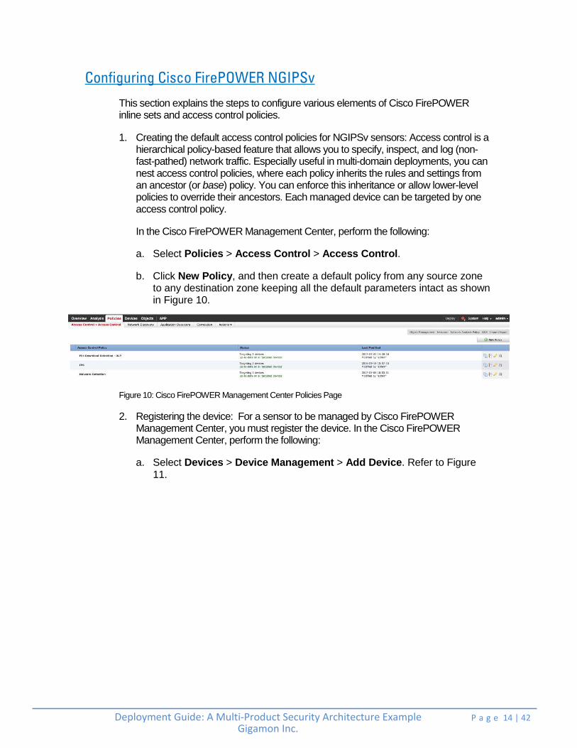
b. Click New Policy, and then create a default policy from any source zone to any destination zone keeping all the default parameters intact as shown in Figure 10.
Figure 10: Cisco FirePOWER Management Center Policies Page
2. Registering the device: For a sensor to be managed by Cisco FirePOWER Management Center, you must register the device. In the Cisco FirePOWER Management Center, perform the following:
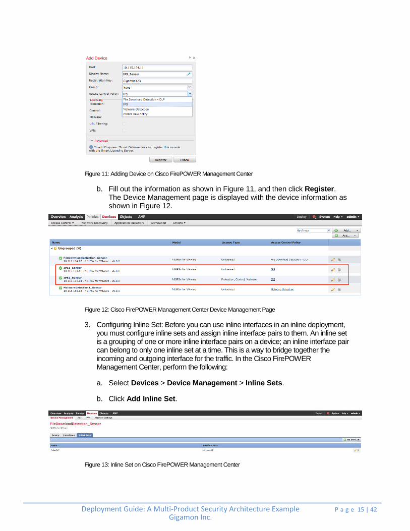
a. Select Devices > Device Management > Add Device. Refer to Figure 11.
Deployment Guide: A Multi-Product Security Architecture Example Gigamon Inc.
P a g e 15 | 42 +
Figure 11: Adding Device on Cisco FirePOWER Management Center
b. Fill out the information as shown in Figure 11, and then click Register. The Device Management page is displayed with the device information as shown in Figure 12.
Figure 12: Cisco FirePOWER Management Center Device Management Page
3. Configuring Inline Set: Before you can use inline interfaces in an inline deployment, you must configure inline sets and assign inline interface pairs to them. An inline set is a grouping of one or more inline interface pairs on a device; an inline interface pair can belong to only one inline set at a time. This is a way to bridge together the incoming and outgoing interface for the traffic. In the Cisco FirePOWER Management Center, perform the following:
a. Select Devices > Device Management > Inline Sets.
b. Click Add Inline Set.
Figure 13: Inline Set on Cisco FirePOWER Management Center
Deployment Guide: A Multi-Product Security Architecture Example Gigamon Inc.
P a g e 16 | 42 +
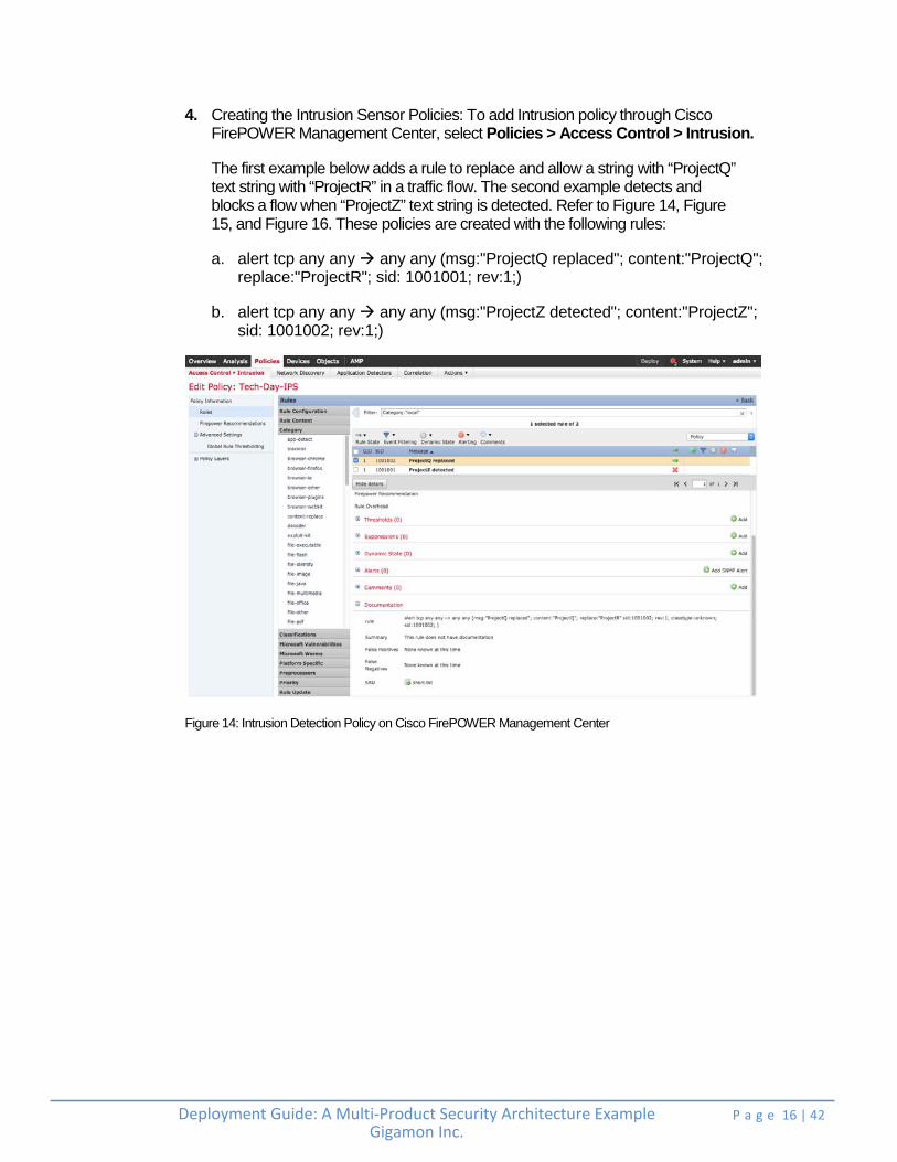
4. Creating the Intrusion Sensor Policies: To add Intrusion policy through Cisco FirePOWER Management Center, select Policies > Access Control > Intrusion.
The first example below adds a rule to replace and allow a string with “ProjectQ” text string with “ProjectR” in a traffic flow. The second example detects and blocks a flow when “ProjectZ” text string is detected. Refer to Figure 14, Figure 15, and Figure 16. These policies are created with the following rules:
a. alert tcp any any any any (msg:"ProjectQ replaced"; content:"ProjectQ"; replace:"ProjectR"; sid: 1001001; rev:1;)
b. alert tcp any any any any (msg:"ProjectZ detected"; content:"ProjectZ"; sid: 1001002; rev:1;)
Figure 14: Intrusion Detection Policy on Cisco FirePOWER Management Center
Deployment Guide: A Multi-Product Security Architecture Example Gigamon Inc.
P a g e 17 | 42 +
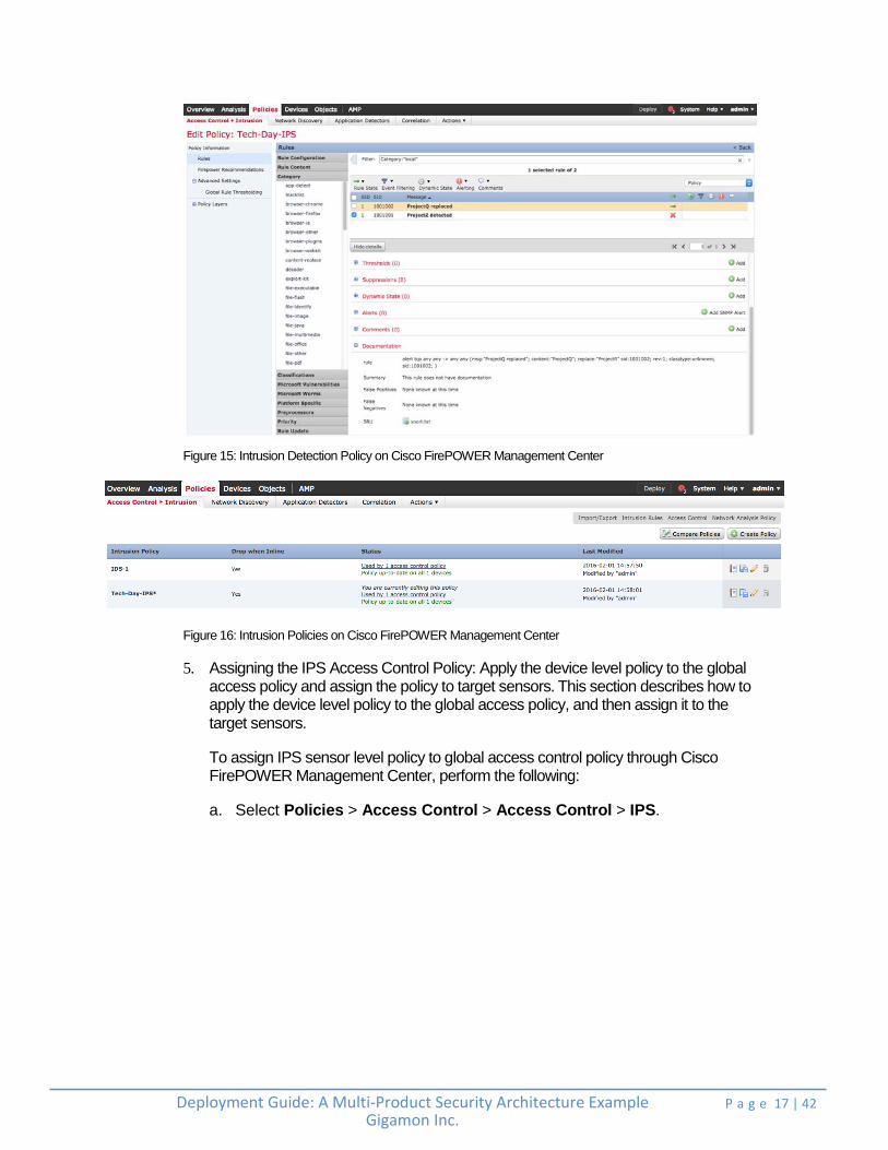
Figure 15: Intrusion Detection Policy on Cisco FirePOWER Management Center
Figure 16: Intrusion Policies on Cisco FirePOWER Management Center
5. Assigning the IPS Access Control Policy: Apply the device level policy to the global access policy and assign the policy to target sensors. This section describes how to apply the device level policy to the global access policy, and then assign it to the target sensors.
To assign IPS sensor level policy to global access control policy through Cisco FirePOWER Management Center, perform the following:
a. Select Policies > Access Control > Access Control > IPS.

Deployment Guide: A Multi-Product Security Architecture Example Gigamon Inc.
P a g e 18 | 42 +
b. Click Edit. The Editing Rule – Monitor Only dialog box is displayed.
Figure 17: Intrusion Policy and Rules on the Cisco FirePOWER Management Center
c. Click the Inspection tab.
d. Select the Intrusion Policy of interest. In Figure 17, the Intrusion Policy selected is Tech-Day-IPS. Click OK.
e. Assign the policy to the targeted devices using the Policy Assignments link in the right hand corner.

Deployment Guide: A Multi-Product Security Architecture Example Gigamon Inc.
P a g e 19 | 42 +
The completed Access control policy page lists the Intrusion policy as shown in Figure 18:
Figure 18: Access Control Policies on the Cisco FirePOWER Management Center
Configuring Splunk Enterprise
This section explains the steps to configure Splunk Enterprise to receive IPFIX metadata from Gigamon. Such metadata enables a number of advanced security use cases to be performed. For more information, refer to https://www.gigamon.com/resources/white-paper/harnessing-power-metadata-security-4068.
Perform the following steps to configure Splunk Enterprise:
1. Configure the Splunk Add-on for IPFIX by navigating to the following link: https://www.gigamon.com/sites/default/files/resources/deployment-guide/dg-gigamon-with-splunk-4053.pdf
2. On the Splunk Enterprise dashboard, navigate to Explore Splunk.
Figure 19: Splunk Enterprise Dashboard with Options
3. Select Add Data as shown in Figure 19.
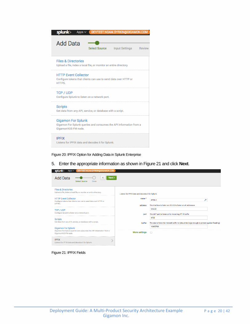
4. Select monitor. On the next screen, select IPFIX as shown in Figure 20.
Deployment Guide: A Multi-Product Security Architecture Example Gigamon Inc.
P a g e 20 | 42 +
Figure 20: IPFIX Option for Adding Data in Splunk Enterprise
5. Enter the appropriate information as shown in Figure 21 and click Next.
Figure 21: IPFIX Fields

Deployment Guide: A Multi-Product Security Architecture Example Gigamon Inc.
P a g e 21 | 42 +
6. After the configuration is complete, a message is displayed as shown in Figure 22.
Figure 22: IPFIX Configuration

Deployment Guide: A Multi-Product Security Architecture Example Gigamon Inc.
P a g e 22 | 42 +
Configuring GigaVUE-HC2
This section covers how to configure GigaVUE-HC2 for all inline network and inline tool elements that you will use to create traffic flow maps. This configuration consists of the following procedures:
Configuring the Inline Network
Configuring the Inline Tools
Configuring the Inline Tool Groups
Configuring the Inline Serial Tools
Configuring the Inline Traffic Flow Maps
Configuring the Inline Network
This section walks you through the steps needed to configure inline network bypass pairs. As the organization’s architecture grows, additional inline network pairs can be added to the inline network group.
The steps described in this section assume that you are logged in to GigaVUE-FM, selected Physical Nodes in the left pane and then selected the GigaVUE-HC2 on the Physical Nodes page.
NOTE: This section assumes all the ports that the network devices are connected to are set as Inline Network port types. For specific instructions on completing these tasks, refer to Gigamon-OS H-VUE User’s Guide.
Configure the Inline Network Bypass Pair
To configure the inline network bypass pair, perform the following:
1. Log into GigaVUE-FM. In the left navigation pane, select Physical Nodes.
2. Double-click the GigaVUE-HC2 from the list of physical nodes GigaVUE-FM is managing.
3. Select Inline Bypass > Inline Networks.
NOTE: If there is a bypass combo module in the GigaVUE-HC2, there will be four preconfigured Inline Network port pairs as shown in Figure 23. If you are using BPS ports, the step will be similar to those covered but limited. Notably, you will not be able to change the alias. Also, port A and port B will be preselected. If your network is 1G or 10G fiber, use one of the preconfigured inline bypass pairs listed in Figure 23.

Deployment Guide: A Multi-Product Security Architecture Example Gigamon Inc.
P a g e 23 | 42 +
Figure 23: Inline Networks view
4. Select an existing Inline Network and click Edit. The Inline Network configuration page is displayed as shown in Figure 24.
Figure 24: Inline Network Pair Configuration
5. On the Inline Network page, perform the following:
a. In the Alias field, type an alias that will help you remember which network link this Inline Network bypass pair represents.
b. Note down the port for Port A and Port B.
Important: It is essential that the side A and side B of the GigaVUE-HC2 match the side A and side B of the Inline Tools. Otherwise, the traffic distribution for the Inline Tool Group will not work correctly.

Deployment Guide: A Multi-Product Security Architecture Example Gigamon Inc.
P a g e 24 | 42 +
c. Retain the Traffic Path and the Link Failure Propagation options set to the default values.
d. Select Physical Bypass. This minimizes packet loss during traffic map changes.
e. Click Save.
NOTE: Traffic Path is set to Bypass to prevent packet loss until the inline tool groups and maps have been set up. After the inline tool groups and maps are configured, the traffic path can be set to inline tool as described in the subsequent section.
Configuring the Inline Tools
This section discusses the configuration steps to add various inline tools.
Adding FireEye NX2400
This section walks you through the steps necessary to define the inline tool port pairs and the inline tool group that will be used in the traffic flow map.
1. On GigaVUE-FM, select Inline Bypass > Inline Tools.
Figure 2625: Navigating to the Inline Tools page
2. Click New to open the configuration page for inline tools as shown in Figure 26.
Deployment Guide: A Multi-Product Security Architecture Example Gigamon Inc.
P a g e 25 | 42 +
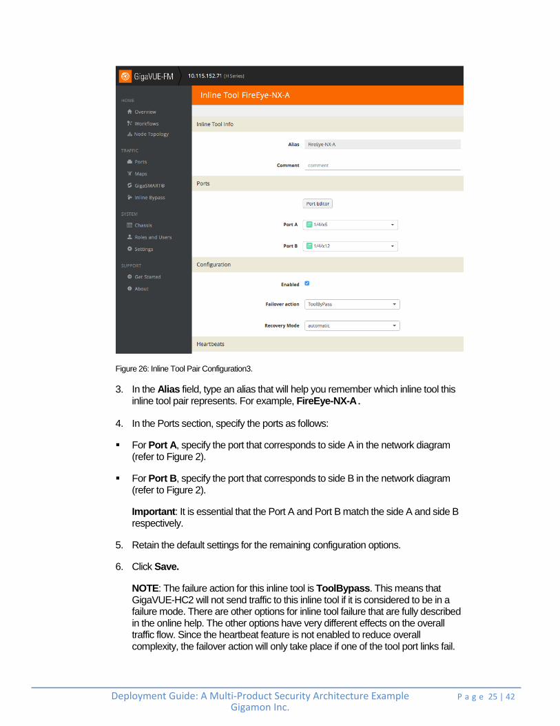
Figure 26: Inline Tool Pair Configuration3.
3. In the Alias field, type an alias that will help you remember which inline tool this inline tool pair represents. For example, FireEye-NX-A.
4. In the Ports section, specify the ports as follows:
For Port A, specify the port that corresponds to side A in the network diagram (refer to Figure 2).
For Port B, specify the port that corresponds to side B in the network diagram (refer to Figure 2).
Important: It is essential that the Port A and Port B match the side A and side B respectively.
5. Retain the default settings for the remaining configuration options.
6. Click Save.
NOTE: The failure action for this inline tool is ToolBypass. This means that GigaVUE-HC2 will not send traffic to this inline tool if it is considered to be in a failure mode. There are other options for inline tool failure that are fully described in the online help. The other options have very different effects on the overall traffic flow. Since the heartbeat feature is not enabled to reduce overall complexity, the failover action will only take place if one of the tool port links fail.

Deployment Guide: A Multi-Product Security Architecture Example Gigamon Inc.
P a g e 26 | 42 +
Adding Palo Alto PA 3020s and Cisco NGIPSv
Repeat steps 1 to 6 as decribed in the Adding FireEye NX2400 section for configuring ports where the Palo Alto PA-3020s and Cisco FirePOWER devices are connected. After the configuration, the Inline Tools page is displayed as shown in Figure 27.
Figure 27: Inline Tools Complete Configuration
Configuring the Inline Tool Groups
To configure the inline tool group, perform the following:
1. In GigaVUE-FM, select Inline Bypass > Inline Tool Groups.
2. Click New to open the Inline Tool Groups configuration page as shown in Figure 28.
Deployment Guide: A Multi-Product Security Architecture Example Gigamon Inc.
P a g e 27 | 42 +
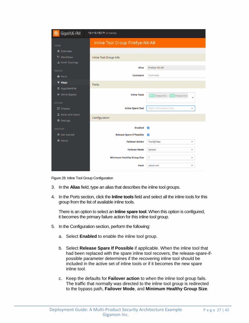
Figure 28: Inline Tool Group Configuration
3. In the Alias field, type an alias that describes the inline tool groups.
4. In the Ports section, click the Inline tools field and select all the inline tools for this group from the list of available inline tools.
There is an option to select an Inline spare tool. When this option is configured, it becomes the primary failure action for this inline tool group.
5. In the Configuration section, perform the following:
a. Select Enabled to enable the inline tool group.
b. Select Release Spare If Possible if applicable. When the inline tool that had been replaced with the spare inline tool recovers, the release-spare-if-possible parameter determines if the recovering inline tool should be included in the active set of inline tools or if it becomes the new spare inline tool.
c. Keep the defaults for Failover action to when the inline tool group fails. The traffic that normally was directed to the inline tool group is redirected to the bypass path, Failover Mode, and Minimum Healthy Group Size.
Deployment Guide: A Multi-Product Security Architecture Example Gigamon Inc.
P a g e 28 | 42 +
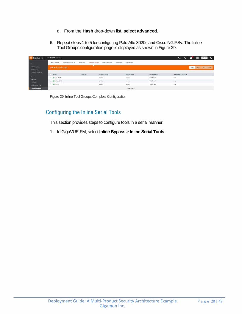
d. From the Hash drop-down list, select advanced.
6. Repeat steps 1 to 5 for configuring Palo Alto 3020s and Cisco NGIPSv. The Inline Tool Groups configuration page is displayed as shown in Figure 29.
Figure 29: Inline Tool Groups Complete Configuration
Configuring the Inline Serial Tools
This section provides steps to configure tools in a serial manner.
1. In GigaVUE-FM, select Inline Bypass > Inline Serial Tools.

Deployment Guide: A Multi-Product Security Architecture Example Gigamon Inc.
P a g e 29 | 42 +
2. Click New to open the Inline Serial Tool Group configuration page as shown in Figure 30.
Figure 30: Inline Serial Tool Group Complete Configuration
3. In the Alias field, type an alias that describes the inline serial tool group.
4. In the Inline Tools drop-down list, select the tools in the order in which the traffic needs to traverse. In the example in Figure 30, the traffic first goes through Palo Alto Networks (Inline Tool Group), then to Cisco FirePOWER (Inline Tool Group), and finally to FireEYE-NX (Inline Tool Group), before being sent out to the network.

Deployment Guide: A Multi-Product Security Architecture Example Gigamon Inc.
P a g e 30 | 42 +
Configuring the Inline Traffic Flow Maps
This section describes the steps for configuring traffic to flow from the inline network links to the inline tool group allowing you to test the deployment functionality of the inline tools within the group. This will be done in two steps as follows:
Configuring the Traffic Flow Map with an Inline Bypass Rule
Changing the Inline Network Traffic Path to Inline Tool
Configuring the Traffic Flow Map with an Inline Bypass Rule
This section covers how to configure the traffic flow map between the inline network group and the inline tool group.
1. In GigaVUE-FM, go to the Maps page.
2. Click New. The New Map page is displayed as shown in Figure 31.
Figure 31: Rule for Inline Network to Tool Flow Map
3. In the Map Info section, perform the following configuration:
a. In the Map Alias field, enter a map alias that represents the network source and tool destination.
b. From the Type drop-down list, select Inline.
c. From the Sub Type drop-down list, select Pass All.
d. From the Traffic Path drop-down list, select Normal.
Deployment Guide: A Multi-Product Security Architecture Example Gigamon Inc.
P a g e 31 | 42 +
4. In Map Source and Destination, set the Source and Destination as follows:
a. Set Source to the first inline network.
b. Set Destination to inline tool group configured previously.
5. Click Save.
Changing the Inline Network Traffic Path to Inline Tool
After configuring the maps, you need to change the traffic path for the inline networks from Bypass to Inline Tool. However, before setting the traffic path to inline tools, make sure that the inline tool ports are up. To check the status of the ports, go to Inline Bypass > Inline Tools.
To change the traffic path from bypass to inline tool, perform the following:
1. In GigaVUE-FM, select Inline Bypass > Inline Networks.
2. Select one of the inline networks that you defined previously and then click Edit.
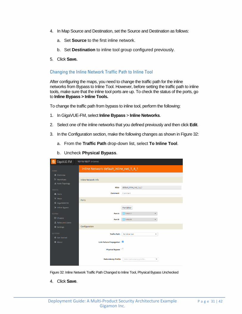
3. In the Configuration section, make the following changes as shown in Figure 32:
a. From the Traffic Path drop-down list, select To Inline Tool.
b. Uncheck Physical Bypass.
Figure 32: Inline Network Traffic Path Changed to Inline Tool, Physical Bypass Unchecked
4. Click Save.
Deployment Guide: A Multi-Product Security Architecture Example Gigamon Inc.
P a g e 32 | 42 +
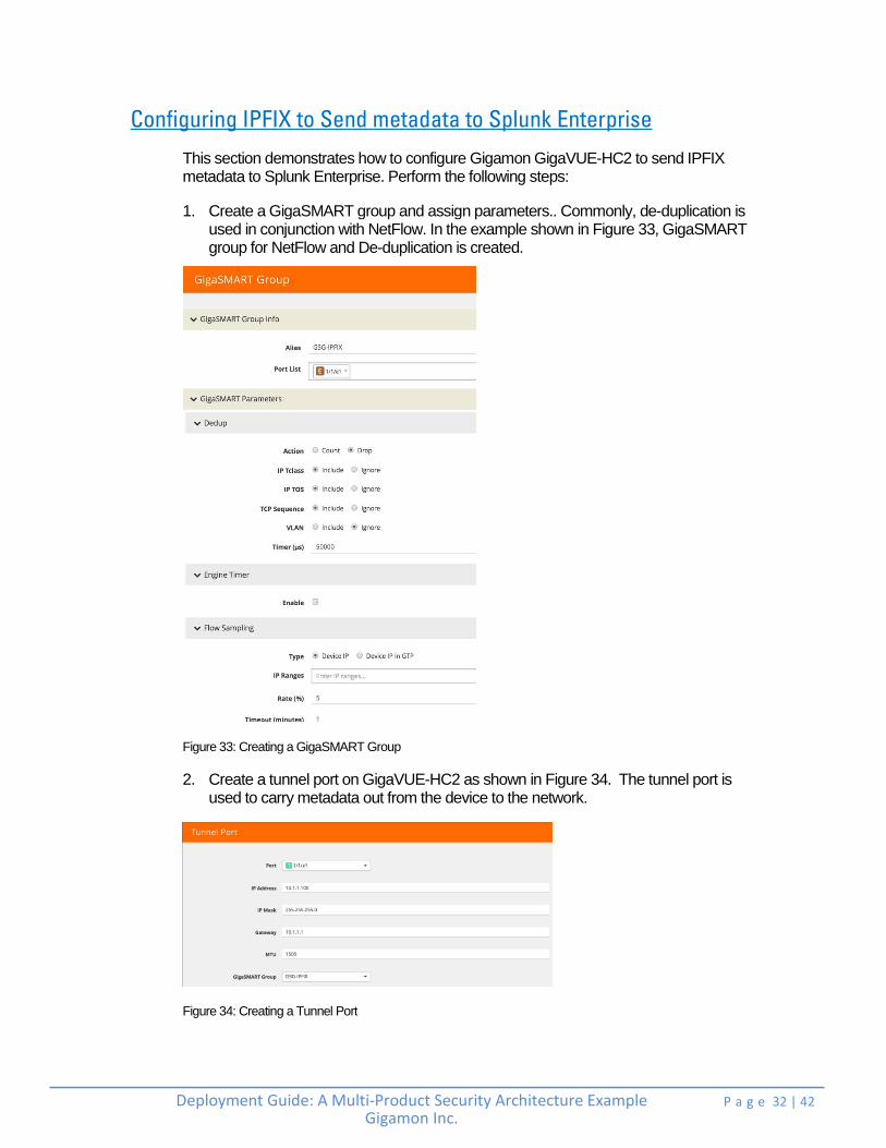
Configuring IPFIX to Send metadata to Splunk Enterprise
This section demonstrates how to configure Gigamon GigaVUE-HC2 to send IPFIX metadata to Splunk Enterprise. Perform the following steps:
1. Create a GigaSMART group and assign parameters.. Commonly, de-duplication is used in conjunction with NetFlow. In the example shown in Figure 33, GigaSMART group for NetFlow and De-duplication is created.
Figure 33: Creating a GigaSMART Group
2. Create a tunnel port on GigaVUE-HC2 as shown in Figure 34. The tunnel port is used to carry metadata out from the device to the network.
Figure 34: Creating a Tunnel Port

Deployment Guide: A Multi-Product Security Architecture Example Gigamon Inc.
P a g e 33 | 42 +
3. Select NetFlow / IPFIX Generation > Records and click New. Configure the Netflow Record as shown in Figure 35 and Figure 36 where some match and collect fields are selected.
Figure 35: Match fields used in NetFlow Record

Deployment Guide: A Multi-Product Security Architecture Example Gigamon Inc.
P a g e 34 | 42 +
Figure 36: Collect fields used in NetFlow Record
Deployment Guide: A Multi-Product Security Architecture Example Gigamon Inc.
P a g e 35 | 42 +
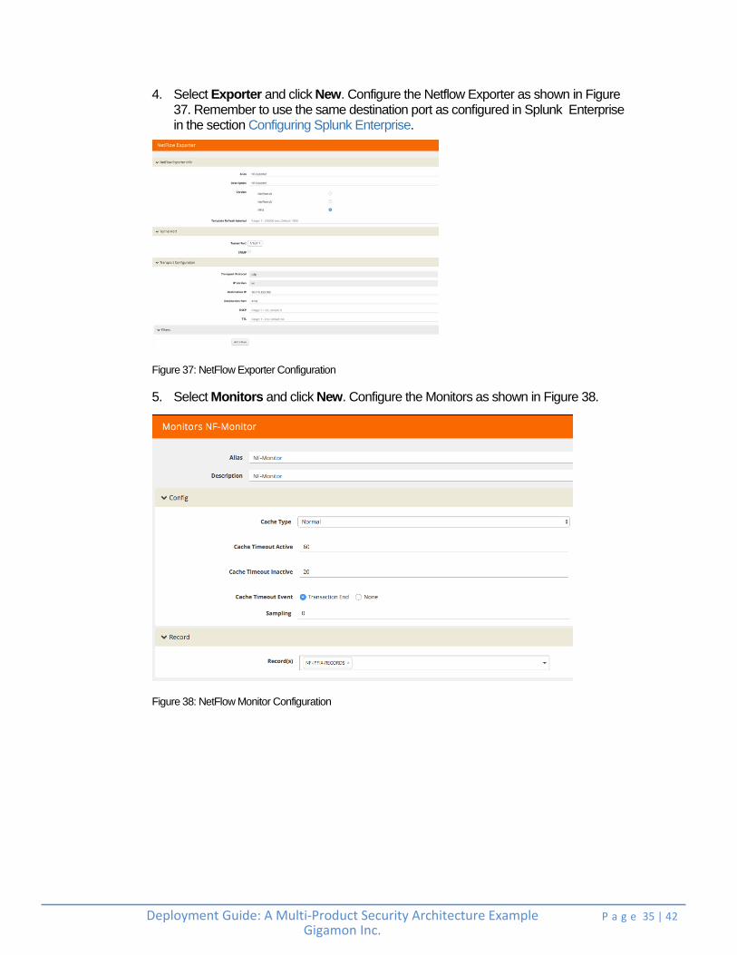
4. Select Exporter and click New. Configure the Netflow Exporter as shown in Figure 37. Remember to use the same destination port as configured in Splunk Enterprise in the section Configuring Splunk Enterprise.
Figure 37: NetFlow Exporter Configuration
5. Select Monitors and click New. Configure the Monitors as shown in Figure 38.
Figure 38: NetFlow Monitor Configuration
Deployment Guide: A Multi-Product Security Architecture Example Gigamon Inc.
P a g e 36 | 42 +
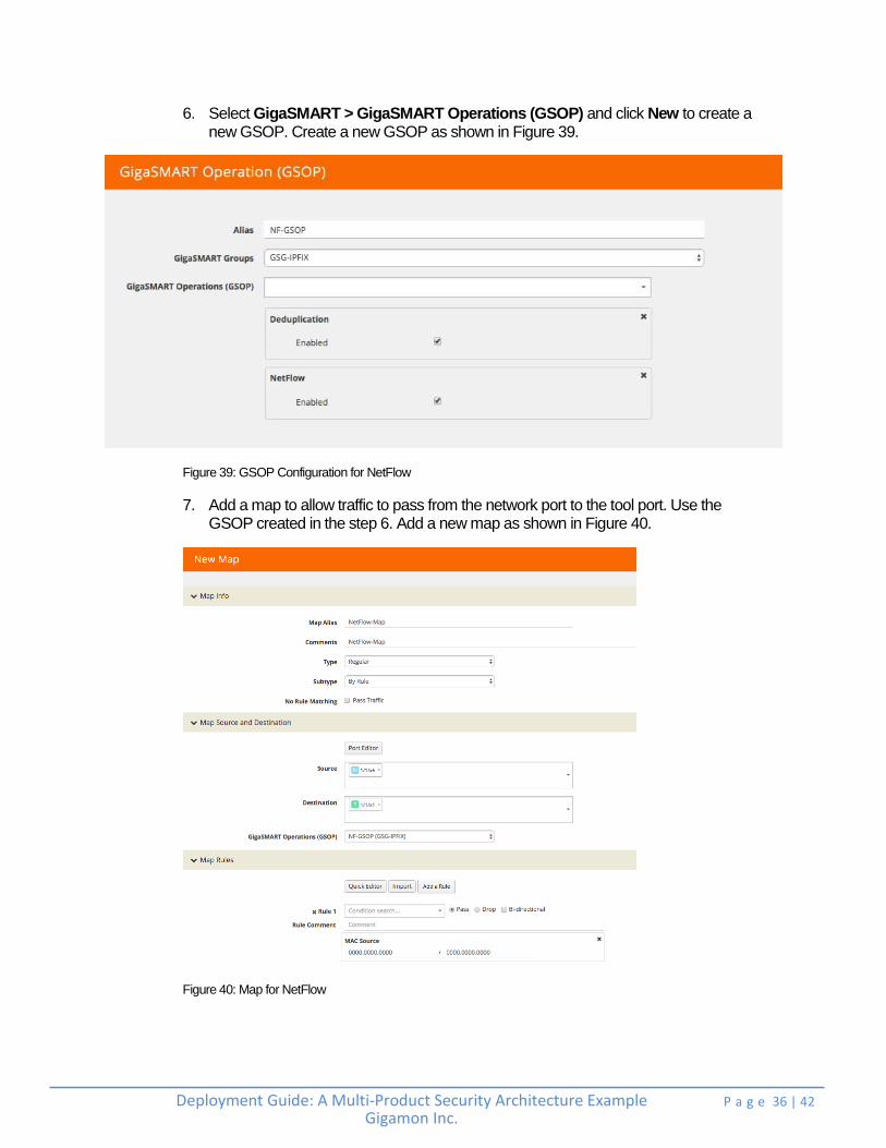
6. Select GigaSMART > GigaSMART Operations (GSOP) and click New to create a new GSOP. Create a new GSOP as shown in Figure 39.
Figure 39: GSOP Configuration for NetFlow
7. Add a map to allow traffic to pass from the network port to the tool port. Use the GSOP created in the step 6. Add a new map as shown in Figure 40.
Figure 40: Map for NetFlow

Deployment Guide: A Multi-Product Security Architecture Example Gigamon Inc.
P a g e 37 | 42 +
8. Select GigaSMART > GigaSMART Groups. Select the GigaSMART Group configured previously and click on Edit. Scroll down to the bottom of the page and click NetFlow. From the Monitor drop-down list, select the monitor created in the step 5. Configure the GigaSMART groups as shown in Figure 41.
Figure 41: GigaSMART Group Configuration
Deployment Guide: A Multi-Product Security Architecture Example Gigamon Inc.
P a g e 38 | 42 +
Other Gigamon Features
Gigamon’s Visibility Platform offers a variety of additional services that combine with services described already in the previous sections.
One can use inline flow mapping to provide the tools with the exact traffic they need, eliminating oversubscription and tool overload. Moreover, GigaSMART® technology extends the intelligence and value of the Gigamon Security Delivery Platform by enhancing the monitoring of your network infrastructure and improving security tool performance.
A range of applications are available to optimize the traffic sent from your network to the tools you rely upon to monitor, manage, and secure the network. GigaSMART’s advanced processing engine can be accessed anywhere within the Gigamon Visibility Platform without port- or card-based restrictions. GigaSMART engines can be combined to manage higher traffic loads and optimized for specific applications. GigaSMART applications can be combined or service chained so the traffic is optimized and delivered based on multiple functions running concurrently, such as decrypting SSL/TLS traffic after packet duplicates have been removed, or stripping VLAN headers before load balancing the traffic and sending it out to the appropriate tools.
Some GigaSMART applications of interest include:
SSL/TLS Decryption: Provides automatic visibility into SSL/TLS traffic regardless of the port or application while sending it to multiple inline or out-of-band tools simultaneously. For more information, refer to the SSL/TLS decryption page (https://www.gigamon.com/products/technology/ssl-tls-decryption).
Application Session Filtering (ASF): Forwards complete application sessions traffic to security appliances increasing their efficacy and performance, classifies flows of interest using signatures to filter applications such as video streaming, email, web 2.0, and other business applications, and provides complete visibility into traffic flows by forwarding all packets from session initiation to termination to security and monitoring tools. For more information, see the feature brief (https://www.gigamon.com/sites/default/files/resources/feature-brief/fb-application-session-filtering-3169.pdf).
Packet Deduplication: Relieves tool processing resources when packets are gathered from multiple collection points along a path or inter-VLAN communications by only forwarding a packet once.

Deployment Guide: A Multi-Product Security Architecture Example Gigamon Inc.
P a g e 39 | 42 +
FlowVUE® : Performs flow-aware sampling of active connections to selectively reduce traffic bound to monitoring and analytic tools. For more information, see the feature brief (https://www.gigamon.com/sites/default/files/resources/feature-brief/fb-flowvue-active-subscriber-aware-flow-sampling-3096.pdf)
Header Stripping: Eliminates the need for monitoring tools to decipher protocols, normalize the data provided to the tools, and allow easy filtering, aggregation, and load balancing of packets with headers removed.
Packet Slicing: Reduces the packet size to increase the processing and monitoring throughput, allowing tools to process fewer bits while maintaining the vital, relevant portions of each packet thus significantly increasing the capacity of forensic recording tools.
For more information on GigaSMART applications, see the GigaSMART data sheet at - https://www.gigamon.com/sites/default/files/resources/datasheet/ds-gigasmart-4003.pdf.

Deployment Guide: A Multi-Product Security Architecture Example Gigamon Inc.
P a g e 40 | 42 +
Summary
The changing threat landscape and evolving network infrastructure are forcing organizations to fundamentally rethink their approach to security in order to keep advanced threats at bay. Security teams are turning to multi-tiered deployments, leveraging the latest threat intelligence tools to protect their network. However, these tools are only as effective as the information they see. The ability to filter through the deluge of Big Data from across the network and scrutinize it in real time is vital to identifying and mitigating advanced threats.
Gigamon’s Visibility Platform offers a comprehensive and sophisticated security services delivery platform. It provides scalability while improving resiliency, simplifying management, and enabling the deployment of best-of-breed security solutions. Gigamon works with security tools to increase their field of vision, improve their performance, support resiliency, reduce troubleshooting times, and accelerate return on investment. The Gigamon Visibility Platform provides the platform for end-to-end visibility coupled with traffic intelligence that is needed to efficiently manage risks and mitigate threats in today’s ever-evolving network environments.

Deployment Guide: A Multi-Product Security Architecture Example Gigamon Inc.
P a g e 41 | 42 +
See Inside Your Network™
4128-01 04/17