design and component integration of a t63-a-700 gas ... · pdf filegas turbine engine test...
TRANSCRIPT
Calhoun: The NPS Institutional Archive
Theses and Dissertations Thesis Collection
1995-09
Design and component integration of a T63-A-700
gas turbine engine test facility
Eckerle, Brian P.
Monterey, California. Naval Postgraduate School
http://hdl.handle.net/10945/35129

NAVAL POSTGRADUATE SCHOOL MONTEREY, CALIFORNIA
THESIS \
l
DESIGN AND COMPONENT INTEGRATION OF A T63-A-700 GAS TURBINE ENGINE TEST
FACILITY
by
Brian P. Eckerle
September 1995
Thesis Advisor: Knox T. Millsaps, Jr.
Approved for public release; distribution is unlimited
19960411 117 DKC QTJALEry INSPECTED l

DISCLAIMER
THIS DOCUMENT IS BEST
QUALITY AVAILABLE. THE COPY
FURNISHED TO DTIC CONTAINED
A SIGNIFICANT NUMBER OF
COLOR PAGES WHICH DO NOT
REPRODUCE LEGIBLY ON BLACK
AND WHITE MICROFICHE.
REPORT DOCUMENTATION PAGE Form Approved OMB No. 0704-0188
Public reporting burden for this collection of information is estimated to average 1 hour per response, including the time for reviewing instruction, searching existing data sources, gathering and maintaining the data needed, and completing and reviewing the collection of information. Send comments regarding this burden estimate or any other aspect of this collection of information, including suggestions for reducing this burden, to Washington Headquarters Services, Directorate for Information Operations and Reports, 1215 Jefferson Davis Highway, Suite 1204, Arlington, VA 22202-4302, and to the Office of Management and Budget, Paperwork Reduction Project (0704-0188) Washington DC 20503
1. AGENCY USE ONLY (Leave blank) 2. REPORT DATE September 1995
REPORT TYPE AND DATES COVERED Master's Thesis
TITLE AND SUBTITLE DESIGN AND COMPONENT INTEGRATION OF A T63-A-700 GAS TURBINE ENGINE TEST FACILITY
5. FUNDING NUMBERS
6. AUTHOR(S) Brian P. Eckerle 7. PERFORMING ORGANIZATION NAME(S) AND ADDRESS(ES)
Naval Postgraduate School Monterey CA 93943-5000
PERFORMING ORGANIZATION REPORT NUMBER
9. SPONSORING/MONITORING AGENCY NAME(S) AND ADDRESS(ES) 10. SPONSORING/MONITORING AGENCY REPORT NUMBER
11. SUPPLEMENTARY NOTES The views expressed in this thesis are those of the author and do not reflect the official policy or position of the Department of Defense or the U.S. Government.
12a. DISTRIBUTION/AVAILABILITY STATEMENT Approved for public release; distribution is unlimited.
12b. DISTRIBUTION CODE
13. ABSTRACT (maximum 200 words) A gas turbine engine test cell was developed integrating an Allison T63-A-700 helicopter engine with a
Superflow water brake dynamometer power absorber. Design specifications were set on all systems and subsystems necessary to operate the engine. Preliminary and detailed designs of the air, water, fuel, and oil systems were developed producing a construction ready overall design. Performance predictions were made which will be compared to experimental data obtained from system operation. Standard Operating Procedures (SOP) and Emergency Operational Procedures (EOP) were developed for engine and auxiliary equipment operation. Preliminary measurements for the structural response of the engine mounting have been made which set engine operating boundaries. The facility has been built and is ready for operation.
14. SUBJECT TERMS Gas Turbine Test Facility 15. NUMBER OF PAGES .175
16. PRICE CODE 17. SECURITY
CLASSIFICATION OF REPORT Unclassified
18. SECURITY CLASSIFICATION OF THIS PAGE Unclassified
19. SECURITY CLASSIFICATION OF ABSTRACT Unclassified
20. LIMITATION OF ABSTRACT UL
NSN 7540-01-280-5500 Standard Form 298 (Rev. 2-89) Prescribed by ANSI Std. 239-18 298-102

11
Approved for public release; distribution is unlimited.
DESIGN AND COMPONENT INTEGRATION OF A T63-A-700 GAS TURBINE ENGINE TEST FACILITY
Brian P. Eckerle Lieutenant, United States Navy
B.S.M.E., Purdue University, 1988
Submitted in partial fulfillment of the requirements for the degree of
MASTER OF SCIENCE BV MECHANICAL ENGINEERING
from the
Author:
Approved by:
NAVAL POSTGRADUATE SCHOOL September 1995
Brian P. Eckerle
'., Thesis Advisor
Matthew D. Kelleher, Chairman Department of Mechanical Engineering
111

IV

ABSTRACT
A gas turbine engine test cell was developed integrating an Allison T63-A-700
helicopter engine with a Superflow water brake dynamometer power absorber. Design
specifications were set on all systems and subsystems necessary to operate the engine.
Preliminary and detailed designs of the air, water, fuel, and oil systems were developed
producing a construction ready overall design. Performance predictions were made which
will be compared to experimental data obtained from system operation. Standard Operating
Procedures (SOP) and Emergency Operating Procedures (EOP) were developed for engine
and auxiliary equipment operation. Preliminary measurements for the structural response
of the engine mounting have been made which set engine operating boundaries. The
facility has been built and is ready for operation.
v

VI
TABLE OF CONTENTS
I. INTRODUCTION 1
II. ENGINE DESCRIPTION 3
A. PRINCIPLES OF OPERATION 3
B. MAJOR COMPONENTS AND ASSEMBLIES 4
C. MAJOR ENGINE SUBSYSTEMS 7
D. GAS TURBINE OPERATIONS 10
E. LEADING PARTICULARS AND
PERFORMANCE RATINGS 11
III. DYNAMOMETER DESCRIPTION 25
A. INTRODUCTION 25
B. PRINCIPLES OF OPERATION 25
C. MAJOR SYSTEM COMPONENTS AND ASSEMBLIES 26
D. MOUNTING MODIFICATIONS 36
IV. GAS TURBINE TEST FACILITY 51
A. INTRODUCTION 51
B. MARINE PROPULSION LABORATORY 51
C. AUXILIARY MACHINERY EQUIPMENT PAD 52
D. GAS TURBINE TEST CELL 52
Vll

V. AUXILIARY SYSTEM DESIGN 61
A. INTRODUCTION 61
B. WATER SYSTEM 61
C. FUEL OIL SERVICE SYSTEM 69
D. AIR SUPPLY AND VENTILATION SYSTEM 74
E. LUBE OIL STORAGE AND CONDITIONING SYSTEM 78
F. ELECTRICAL SYSTEM 81
VI. HEAT EXCHANGER ALTERNATIVE STUDY 93
A. INTRODUCTION 93
B. ANALYSIS 94
C. CONCLUSIONS AND RECOMMENDATIONS 104
VII. STANDARD AND EMERGENCY OPERATIONAL
PROCEDURE „119
A. INTRODUCTION 119
B. MASTER LIGHT OFF CHECKLIST (MLOP) 120
C. FUEL OIL SYSTEM RECIRCULATION PROCEDURE
(FOSRP) 120
D. COOLING WATER SYSTEM RECIRCULATION
PROCEDURE (CWSRP) ..121
E. MASTER NORMAL SHUTDOWN PROCEDURE (MNSP) 121
F. EMERGENCY SHUTDOWN PROCEDURE (ESP) 121
G. SUMMARY 122
Vlll

VIII. CONCLUSIONS AND RECOMMENDATIONS 123
APPENDIX A. DETAILED DRAWINGS OF GAS TURBINE ENGINE
MOUNTING SUPPORTS AND TORQUE PLATE 125
APPENDIX B. EQUIPMENT LISTING FOR THE AUXILIARY
MACHINERY PAD 129
APPENDIX C. AUXILIARY SUPPORT SYSTEMS EQUIPMENT
LISTING 131
APPENDIX D. MATLAB COMPUTER SIMULATION PROGRAM
CODE 137
APPENDIX E. STANDARD OPERATIONAL PROCEDURES FOR
ALIGNMENT AND OPERATION OF THE GAS TURBINE AND
DYNAMOMETER TEST SYSTEM 143
LIST OF REFERENCES 161
INITIAL DISTRIBUTION LIST 163
IX

I. INTRODUCTION
Gas turbine engines are the principal means of propulsion and electrical power
production used in surface combatant ships. Therefore, it is paramount that all Naval
Officers have a good working understanding of the principles of operation and capabilities
provided by gas turbine engines. The development of the Gas Turbine Test Facility as part
of the Marine Propulsion Laboratory will play a key role in educating Naval Officers by
providing hands on instruction in engine operations, as well as, component familiarization
provided by data collection and engine cycle analysis.
The purpose of this project was to produce a system design and component
integration of a T63-A-700 gas turbine engine with a Superflow 901-SF water brake
dynamometer and develop a functioning gas turbine test facility. The gas turbine test
facility will be used in conjunction with Mechanical Engineering course, ME 3241, a gas
turbine and Diesel power plant performance analysis laboratory.
The gas turbine test cell along with a Diesel cell comprise the Marine Propulsion
Laboratory in the Mechanical Engineering Building. Although the Diesel test cell and its
identical dynamometer will utilize many of the same auxiliary support systems as the gas
turbine engine, the auxiliary support systems are designed for compatibility with the
generally more demanding and limiting parameters of the gas turbine engine. Therefore, all
discussions and calculations of system requirements for the auxiliary support systems and
their designs will be conducted with respect to the gas turbine test facility. The following
paragraphs are an overview of the subject matter contained in this paper.
Chapter II is a description of the T63-A-700 gas turbine engine. The principles of
operation, major components and assemblies which includes the compressor, gas generator
turbine and power turbine, engine subsystems, and performance parameters are discussed.
1

Chapter III contains a description of the Superflow 901-SF dynamometer test
system. The principles of operation, major system components, control console
configurations and operations, as well as, the engine mounting and shafting modifications
are also discussed.
The physical layout of the Marine Propulsion Laboratory is shown in Chapter IV.
The auxiliary support equipment, positioned on the auxiliary machinery equipment pad, is
listed along with the physical dimensions of the gas turbine test cell.
Chapter V contains a discussion of the design criteria and considerations involved
in integrating the generic auxiliary support equipment, provided during construction of the
Mechanical Engineering Building with components specifically designed or purchased for
use with the T63-A-700 gas turbine engine. Complete system schematics and design
parameters are presented. An equipment listing for the water cooling, fuel, air, oil, and
electrical support systems is contained in Appendix C.
The purpose of Chapter VI is to conduct a thermodynamic computer simulation of
the water cooling system in order to predict system performance. Transient and steady state
heat transfer analyses were completed to set time limits for system operation at various
power settings. Alternatives to the present configuration, which were found to be
insufficient in supporting gas turbine operations in the steady state at full power, are
discussed.
Standard operational procedures for engine light off, fuel oil, and water system
recirculation, along with normal and emergency shutdown procedures are contained in
Chapter VH.
In Chapter VIII, a summary of the overall system design along with its limitations
are discussed along with recommendations for future work which will improve system
performance and enhance system operation.

II. ENGINE DESCRIPTION
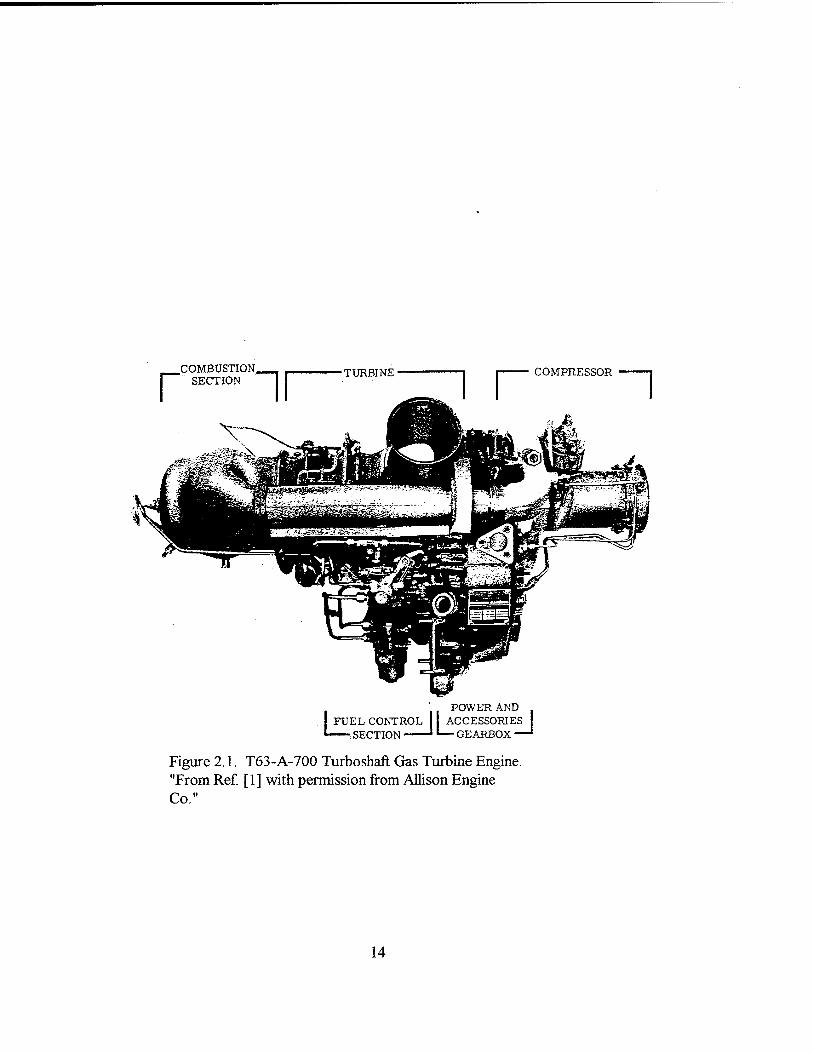
A. PRINCIPLES OF OPERATION
The gas turbine engine is a Model 250-C18 / T63-A-700 (military) turboshaft
engine which is manufactured by Allison Division, General Motors Corporation,
Indianapolis, Indiana (Figure 2.1). The engine is relatively small, weighing approximately
140 pounds, and is principally used in the U.S. Army OH-58 light observation helicopter.
Over 5,000 engines were delivered for service to the U.S. Military and over 25,000
engines in the Series were manufactured for both military and civilian applications making
this engine one of the most produced gas turbine engines to date. The design output power
of the engine is 317 SHP at 35,000 power turbine RPM, gearing down to 6,000 RPM at
the engine output drive spline, with an air flow of 2,600 SCFM at standard conditions.
The specific fuel consumption at full power is 0.697 LB/SHP-HR and the compressor
pressure ratio is 6.18:1. The maximum turbine inlet temperature at maximum power is
1,380 °F. [Ref. 1: p. 1-2]
Ar enters the engine through a seven stage compressor consisting of six axial
stages followed by one centrifugal stage. The compressed air is discharged through a
scroll type diffuser into two external ducts which direct the air into a single, reverse flow
combustion chamber located in the rear of the engine. The air is mixed with fuel sprayed
through a single fuel nozzle mounted at the aft end of the combuster where the fuel is
ignited by one igniter plug.
The compressor is driven by a direct shaft from an axial two-stage gas generator
turbine which also drives an accessories gear train. The accessories gear train provides
input power to the lube oil supply and scavenge elements, as well as, the fuel pump and

gas generator fuel control. The engine is a free turbine engine in which there is no
mechanical connection between the gas producer turbine and the power turbine. The power
turbine is gas coupled to the gas producer turbine by combustion gases. A two-stage
helical reduction gear in the power turbine and accessories gear box is used to reduce the
power turbine speed from 35,000 RPM to 6,000 RPM at the output drive spline. The
various components will now be discussed in some detail.
B. MAJOR COMPONENTS AND ASSEMBLIES
1. Compressor Assembly
The engine utilizes a seven stage compressor consisting of six axial stages followed
by one centrifugal stage combining for a compression ratio of 6.18:1 at a speed 51120
RPM which corresponds to an axial air speed of 0.43 Mach and a mass flow rate of 3.3
LBM/SEC. The compressor efficiency at full power is 85% with a temperature increase of
450 °F across the compressor. The compressor assembly (Figure 2.2) consists of a
compressor front support, a case assembly with stator vanes, a rotor assembly, a
centrifugal impeller, a front diffuser assembly, a rear diffuser assembly, and a diffuser
scroll. Air enters the compressor through the front support where struts guide and direct
the air into the first stage of the compressor rotor. The diffuser scroll collects the
compressor discharge air at a constant velocity and directs it rearward through two tubes
into the combustion section.

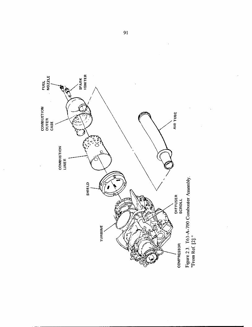
2. Combustion Section
The combustion section (Figure 2.3) consists of two compressor discharge air
tubes, a combustion outer case, and a combustion liner. The outer combustion case, which
houses the combustion liner, is attached to the gas producer turbine support through a
bolted flange. The combustion liner is supported at the forward end by the gas producer
nozzle vane assembly and at the rear by the fuel nozzle. Compressor discharge air is
ducted from the diffuser scroll to the combustion outer case by two compressor discharge
air tubes. Air enters the combustion liner at the rear through holes in the liner and is mixed
with fuel sprayed from a single fuel nozzle. The mixture is then ignited by a single spark
igniter installed in the rear of the outer combustion case causing the combustion gases to
move forward out of the combustion liner into the power turbine assembly.
During maintenance and cleaning of the fuel nozzle and igniter, the maintenance
person must not remove both the igniter and fuel nozzle simultaneously. If the combustion
liner is loose, which often occurs after significant gas turbine operation, the combustion
liner will fall against the outer case and prevent reinsertion of the igniter and fuel nozzle into
the holes. Realignment of the two holes may only be accomplished through disassembly of
the combuster, a time consuming operation.
3. Turbine Assembly
A two-stage gas generator turbine, a two-stage power turbine, and a turbine exhaust
collector make up the turbine assembly. The turbine assembly is located immediately
forward of the combuster as shown in Figure 2.4. The 100% design speeds of the gas
generator turbine and the power turbine are 51,120 RPM and 35,000 RPM respectively.

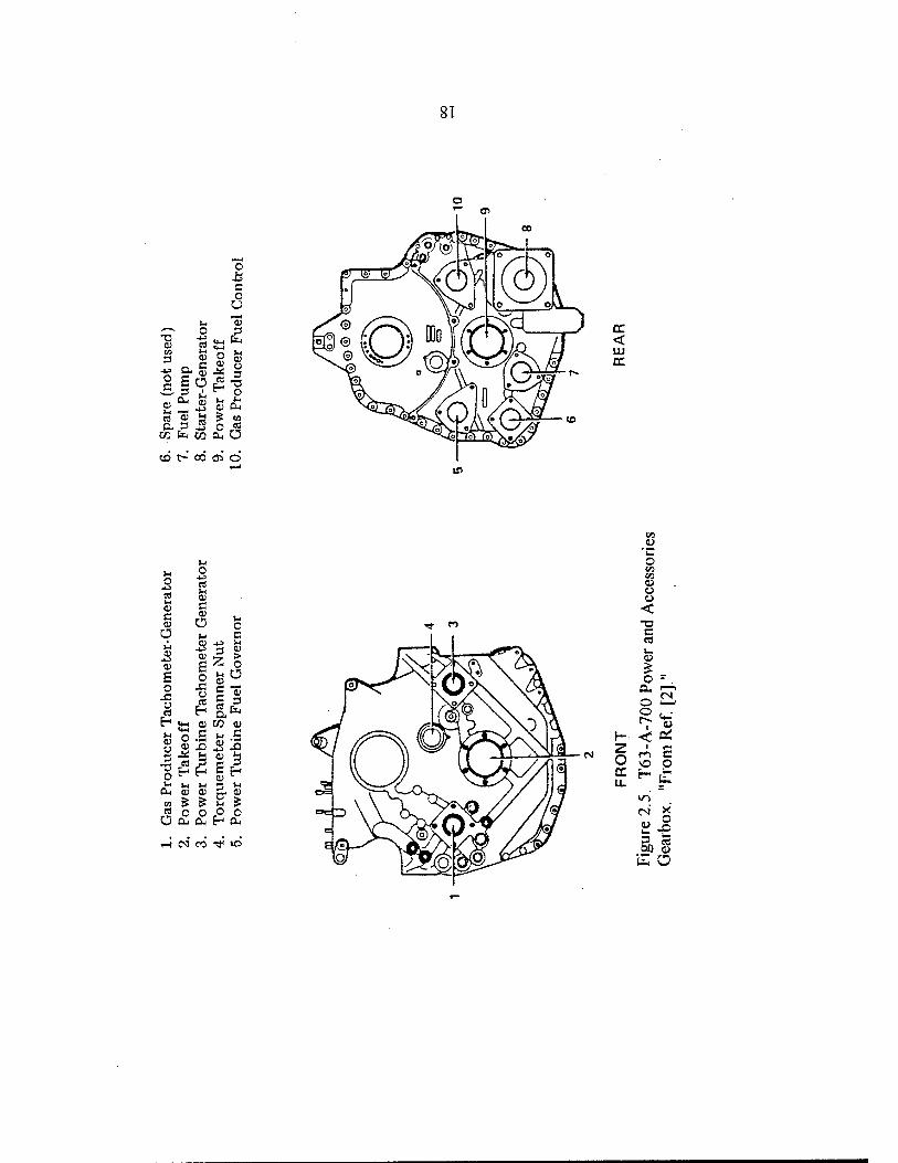
4. Power and Accessories Gearbox
A single, enclosed cast gearbox housing (Figure 2.5) serves as the structural
support for the engine and as an enclosure for the main power and accessory drive train.
Power is transmitted from the power turbine to the output drive spline through a double
helical reduction gear with a reduction ratio of approximately 5.83:1. Included in the
accessory drive train is an input shaft for the starter / generator and output gearing to drive
the attached fuel pump. The pressure and scavenge oil pumps are also enclosed in the
gearbox housing and are driven by the gas generator turbine.
5. Torque Sensor
The first-stage driven and second-stage driving gear are integrally mounted on the
torque meter shaft as shown in Figure 2.6. During normal operation, a forward axial thrust
is imparted on the torque meter shaft from the helix angles of the helical reduction gears.
This axial thrust is transmitted to a counterbalanced oil piston, which utilizes oil from the
lubrication system. A change in cylinder pressure, caused by the axial thrust, is provided
to an external connection for gauge measurement. The units of torque measurement is
therefore measured in PSIG rather than in FT-LB. Shaft torque is also one of the
parameters measured by the dynamometer and is displayed in the units of FT-LB. This will
be the principal means of measuring and monitoring shaft torque. A more detailed
description of the torque sensor is contained in the installation design manual.
[Ref. l:p. 1-6]
C. MAJOR ENGINE SUBSYSTEMS
1. Lubrication System
The lubrication system is a circulating dry-sump system with supply and scavenge
elements enclosed in the accessory gearbox as shown in Figures 2.7 and 2.8. An external
oil cooler and storage tank provide both storage and cooling of MEL-L-23699 gas turbine
lubricating oil. MIL-L-7808 lubricating oil may be used as an alternative however, MIL-L-
23699 and MIL-L-7808 should not be mixed. An oil filter, a filter bypass valve, and a
pressure regulating valve are installed as a filter package, which is accessible from the top
of the engine, in the upper right hand side of the gearbox housing. A check valve is
positioned between the filter package and the accessory gearbox. All engine lines, with the
exception of the pressure and scavenge lines to the compressor front bearing and bearings
in the gas generator and power turbine supports, are internal to the engine. Indicating,
probe-type magnetic chip detectors are installed at the bottom of the power and accessory
gearbox and at the oil outlet connection. Whenever a metal chip shorts the open circuit in
the chip detector, an indicating light will illuminate. This warning light is located in the
airframe therefore an indicating light will be installed on the dynamometer stand for
monitoring purposes.
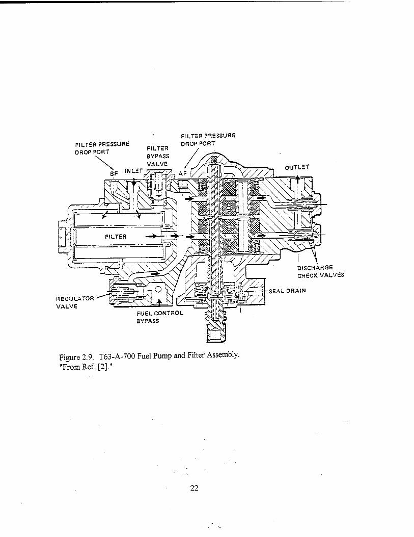
2. Fuel System
Diesel Fuel #2 is the fuel type used in this test facility. The fuel is pumped by two
gear type pumping elements located in the fuel pump and filter assembly as shown in
Figure 2.9. The use of Diesel Fuel #2 vice JP-4, the fuel used in aircraft applications, is

discussed in Chapter V Section B. The pumping elements are arranged in tandem and
driven by a common drive shaft. Fuel enters the engine fuel system at the inlet port of the
pump and passes through a low pressure, 5 micron filter before entering the gear elements.
The gear elements, which are arranged in a parallel configuration, each have the capacity to
provide sufficient fuel supply if the other pumping element should fail. Two discharge
check valves are installed to prevent reverse flow in the event of failure of either pumping
element. A bypass valve is also installed in the fuel pump and filter assembly to allow fuel
to bypass the fuel filter if blockage occurs. The bypass fuel is directed through a pressure
regulating valve, which maintains bypass flow pressure above the inlet pressure, to the
inlet of the gear elements. The fuel discharged from the supply elements is routed to the
fuel nozzle by external fuel lines to the rear of the engine. A single-entry, dual-orifice type
fuel nozzle is used to spray fuel into the rear of the combustion liner. The fuel nozzle also
contains an integral valve for dividing primary and secondary fuel flow and also acts as a
fuel shutoff valve to prevent fuel from entering the combuster in low pressure situations
and during shutdown.
3. Ignition System
A capacitor discharge ignition exciter, a spark igniter lead, and a shunted-surface
gap spark igniter make up the engine ignition system, displayed in Figure 2.10. The
ignition system receives its power from two-12 volt DC batteries externally mounted in
series which provide a 24 volt DC power supply to the starter / generator and exciter. The
spark igniter lead transfers this energy to the spark igniter attached at the rear of the
combuster. The spark igniter utilizes this energy to produce a high temperature, high
current arc at the spark igniter gap igniting the fuel / air mixture.
4. Control Systems
The engine control systems control engine power output by controlling the gas
generator turbine speed. The power turbine fuel governor lever schedules the power
requirements demanded by the operator and schedules the gas generator speed to maintain
output shaft speed.
a. Temperature Measurement System
The temperature measurement system consists of four chromel-alumel
(K-type), single junction thermocouples at the power turbine inlet. The voltages of the four
thermocouples are electrically averaged in the assembly and delivered to a terminal block
for connection to an indicator. A complete data acquisition system with separate
thermocouples will be used in conjunction with the existing system. Instrumentation plans
which are being developed prior to full integration of the engine into the test cell, involve
disassembly of the combuster and placement of a thermocouple ring within the combuster
for extensive temperature measurement. This procedure will lengthen the combuster
section approximately 3 inches.
b. Gas Generator Fuel Control System
The gas generator turbine fuel control utilizes a bypass valve, a metering
valve, an acceleration bellows, a governing and enrichment bellows, a manually operated
cutoff valve, a maximum pressure relief valve, and a lever assembly to control fuel flow.
Fuel is discharged from the fuel pump and filter assembly into the fuel control and is
directed to the metering valve. The bypass valve maintains a constant pressure differential
across the metering valve and bypasses excess fuel back to the fuel pump and filter
assembly through an external line. The metering valve is operated by lever action through
the movement of the governor and acceleration bellows. This lever action controls the
extent of the flow orifice opening. Gas generator speed is controlled by a set of flyweights
that operate the governor lever thereby, regulating air pressure to the governor and
acceleration bellows. The governor actuates the metering valve and regulates fuel flow.
The flyweight operation is opposed by variable spring loading established by the throttle
lever acting on a spring scheduling cam. [Ref. 2: p. 1-13]
c. Power Turbine Governor Control System
The power turbine speed is scheduled by the power turbine governor lever
and spring scheduling cam. This action regulates spring load against flyweights similar to
the action described above in the gas generator and in turn controls the fuel metering valve
in the fuel control governor. The power turbine governor also provides overspeed
protection by providing rapid air pressure bleed capability to limit fuel metering valve
actuation.
D. GAS TURBINE OPERATIONS
The present laboratory course, ME 3241, utilizes a Boeing 502-A gas turbine
engine for performance analysis. During engine testing, the gas generator turbine speed
(Ni) is fixed at a predetermined speed, and the power turbine speed (N2) is varied.
Measurements of engine parameters are taken at each power turbine speed and performance
curves are developed.
10
In the OH-58 helicopter, the airframe for which the T63-A-700 engine is designed,
the power turbine and output shaft speed are fixed at approximately 35,000 RPM and
6,000 RPM respectively. As the helicopter main rotor trim (blade pitch) is changed, the
power turbine governor provides input to the gas generator fuel control scheduling fuel to
the combuster and thereby, changing gas generator turbine speed. In other words, N\ is
highly variable with rotor blade loading while N2 is fixed.
In order to utilize the T63-A-700 gas turbine engine in the ME 3241 course and
conduct the engine performance evaluation in a similar manner as with the Boeing engine,
an instrumentation plan is being developed in conjunction with Allison Gas Turbine
[Ref. 3] to alter the power turbine governor input to the gas generator fuel control. This
modification will allow the gas generator speed to remain fixed while varying output shaft
speed and in turn the power turbine speed. Gas generator (Nl) and power turbine (N2)
speeds will be monitored at the dyno console using the existing tachometer gearing and
custom-made magnetic tachometers and meters manufactured by Turbomotive, Inc.
[Ref. 4]
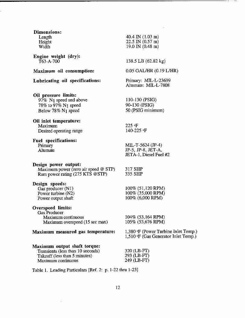
E. LEADING PARTICULARS AND PERFORMANCE
RATINGS
The leading particulars for the T63-A-700 engine are listed in Table 1. The
performance ratings for the engine at standard sea level static conditions are displayed in
Table 2.
11
Dimensions: Length Height Width
Engine weight (dry): T63-A-700
Maximum oil consumption:
Lubricating oil specifications:
Oil pressure limits: 97% Ni speed and above 78% to 97% Ni speed Below 78% Ni speed
Oil inlet temperature: Maximum Desired operating range
Fuel specifications: Primary Alternate
Design power output: Maximum power (zero air speed @ STP) Ram power rating (275 KTS @STP)
Design speeds: Gas producer (NI) Power turbine (N2) Power output shaft
Overspeed limits: Gas Producer
Maximum continuous Maximum overspeed (15 sec max)
Maximum measured gas temperature:
Maximum output shaft torque: Transients (less than 10 seconds) Takeoff (less than 5 minutes) Maximum continuous
40.4 IN (1.03 m) 22.5 IN (0.57 m) 19.0 IN (0.48 m)
138.5 LB (62.82 kg)
0.05 GAL/HR (0.19 L/HR)
Primary: MBL-L-23699 Alternate: MIL-L-7808
110-130 (PSIG) 90-130 (PSIG) 50 (PSIG minimum)
225 °F 140-225 °F
MIL-T-5624 (JP-4) JP-5, JP-8, JET-A, JETA-1, Diesel Fuel #2
317 SHP 335 SHP
100% (51,120 RPM) 100% (35,000 RPM) 100% (6,000 RPM)
104% (53,164 RPM) 105% (53,676 RPM)
1,380 °F (Power Turbine Inlet Temp.) 1,510 °F (Gas Generator Inlet Temp.)
320 (LB-FT) 293 (LB-FT) 249 (LB-FT)
Table 1. Leading Particulars [Ref. 2: p. 1-22 thru 1-23]
12

Rating Shaft Horsepower (HP)
Gas Generator Speed (RPM)
Output Shaft Speed (RPM)
Air Flow (SCFM)
Specific Fuel Consumption (LB/SHP-HR)
100% 317 51,120 6,000 2,600 0.697
90% 243 48,650 6,000 2,150 0.725
75% 203 46,950 6,000 1,685 0.762
Startand Idle
35 32,000 500-6,300 61LB/HR
Table 2. T63-A-700 Performance Ratings [Ref. 1: p.1-2]
13
COMBUSTION. SECTION
■TURBINE COMPRESSOR
[TO FUEL CONTROL SECTION Jl
POWER AND ACCESSORIES
— GEARBOX '
Figure 2.1. T63-A-700 Turboshaft Gas Turbine Engine. "From Ref. [1] with permission from Allison Engine Co."
14

15
91
s <
o U o o
u-; ci <u cs e£ V c u 3 o 01) —.
li, r

s> CO CO
<
-- X> 3
O o
so H
tN V u. 3 00 £ =
<N
o i-
17
8T
o a o a
•a a> 05 3 +s O c
o a)
a s .5 u ~ C/D fa ca a. G
o
£ to o
(flt-B<BO
< UJ DC
<* *">
HNTOTflO
a) (L> u O Vi V} O O o < T3 C eC u. a> 5 o - .
0- T ^ c^ O '—i
K <es z o o o a. u.
l/->
cs x .. o
DO a) s o

■HYDRAULIC TORQUEMETER SHAFT
STATIONARY , PISTON
PRESSURE SENSING LINE TO
GAGE -
POWER INPUT PINION MESHES HERE
DIRECTION OF HELICAL GEAR
THRUST ON TORQUEMETER
SHAFT
■E
SLIDING CYLINDER
INLET PORT TO PRESSURE
CHAMBER
#J////fffSA>y###lr#M»j*jM»*7n
POWER
TTT»
TAKE-OFF !&&*# SHAFT
Figure 2.6. T63-A-700 Torque Sensor. "From Ref. [1] with permission from Allison Engine Co."
19

SCAVENGE PUMP ELEMENTS
FROM COMPRESSOR FRONTSUPPORT
FROM GAS PRODUCER SUPPORT
PRESSURE PUMP ELEMENT
FROM POWER TURBINE SUPPORT/ / /
FROM PRESSURE REGULATING VALVE
FROM LOWER ACCESSORY GEARBOX
DISCHARGE TO ACCESSORY GEARBOX COMMON OUTLET PASSAGE
^•BYPASS OIL SCAVENGE OIL WZ PRESSURE OIL iR ■ •■) SUPPLY OIL
Figure 2.7. T63-A-700 Supply and Scavenge Pump Elements. "From Ref. [2]."
20

irrrier€iietrtirritrrr/IHIIH/ltt/T^-nllnnmrrrrr/tftirrrrnrrrrrr
(3 O
'■£ c cö o O co
"C ~ -§< J s 2 o
.S cfc
tu .2 « co c •?
£ u
co "5 CO *c ü £ O _ O 1—1
<*> c VO C
*- 8. . tu • 00= o
C<1
c« a> S
fe «5 W
21
FILTER PRESSURE DROP PORT
FILTER PRESSURE DROP PORT
OUTLET
REGULATOR VALVE
FUEL CONTROL BYPASS
^»l^fesrSEAL
DISCHARGE CHECK VALVES
DRAIN
Figure 2.9. T63-A-700 Fuel Pump and Filter Assembly. "From Ref. [2]."
22

SPARK GNITSR
AUTO RE1GNIT10N
CONTROL EXCITER
Figure 2.10. T63-A-700 Electrical Ignition System. "From Ref. [2]."
IGNITION LEAD
23

24

III. DYNAMOMETER DESCRIPTION
A. INTRODUCTION
The engine dynamometer test system is a model SF-901 dynamometer which is
manufactured by Superflow Corporation, Colorado Springs, Colorado. Since the principal
application for the SF-901 test system is high performance internal combustion engine
testing, various modifications were made to the existing system in order to facilitate
compatibility with a gas turbine engine.
In this chapter, the principles of operation and major system components are
discussed along with proposed console operations and configurations. A discussion of the
structural modifications to the engine stand for mounting of the T63-A-700 engine is
presented along with figures showing mounting details and measurements. Lastly, a
description of the shafting modifications, as well as, the procedures used to determine shaft
natural frequencies is introduced.
B. PRINCIPLES OF OPERATION
The gas turbine engine is mounted via a direct coupled shaft to a water brake
dynamometer. The SF-901 dynamometer employs a water brake power absorption unit to
provide loading for the power turbine. The maximum capacity of the power absorption
unit (SF-801) is a torque of 1,000 FT-LB with a maximum rotational speed of 10,000
RPM for normal, continuous operation. However, the power absorber has the capability to
withstand 12,000 RPM for brief periods with resultant reduced bearing life. Although this
system is used principally for testing of internal combustion engines, it is quite sufficient to
25

handle the power requirements of the T63-A-700 gas turbine engine which transmits a
maximum torque of 293 FT-LB with a normal output shaft speed of 6,000 RPM. A torque
verses speed curve is presented in Figure 3.1 and shows an approximate torque curve for
the engine superimposed with the maximum torque capacity curve for SF-801 power
absorber. One can see for operating speeds greater than 2,200 RPM, the dynamometer will
handle the engine torque quite effectively.
The SF-901 test system includes an engine stand, an engine cooling tower, a fuel
system, and a 486 IBM compatible computer and printer system. Measuring devices for air
flow, fuel flow, and oil pressure and their respective temperatures are also included.
C. MAJOR SYSTEM COMPONENTS AND ASSEMBLIES
1. Engine Stand
The engine stand, which is supported by four large casters for mobility, is the basic
support structure for the engine, power absorber, fuel system, and cooling tower as shown
in Figure 3.2. The engine stand also provides the instrumentation connections from all
sensors and measurement devices to the dynamometer control console. An oil drip pan,
battery storage rack, and water sump tank are also mounted on the engine stand.
2. Power Absorption Unit
A water brake power absorption unit is utilized to provide the necessary engine
loading for adequate engine testing and performance analysis. The power absorber, filled
with pressurized water, contains an impeller which resists the rotation of the engine output
shaft thereby loading the engine. An external, closed water system, discussed in
26

Chapter V, provides a pressurized water supply to the power absorber for engine loading,
as well as, cooling water to the water brake.
A LOAD CONTROL switch, located on the control console as shown in Figure
3.3A, adjusts the load applied to the engine by the power absorption unit. A rapidly
variable water valve, which is located at the absorption unit discharge, regulates the
discharge of water from the power absorber to maintain the required pressure within the
absorber for proper load control. The load control can be operated in two modes,
MANUAL and SERVO. In MANUAL mode, the load control maintains the same load on
the engine at all RPM. When operated in SERVO mode, the load is variable and maintains
a constant engine RPM regardless of throttle position. With this dual mode capability, it is
possible to start the engine and idle in MANUAL mode at one constant load. After warm
up, the operator can switch to SERVO mode and take the engine to full throttle for engine
testing. A capacity valve, which is shown in Figure 3.3B, is used to adjust the
dynamometer power absorption capacity. This is useful in controlling the sensitivity of the
load control adjustment knobs by setting the capacity valve at the maximum load capability
so that the full operating range of the absorption unit may be utilized during engine testing.
[Ref. 5: p. 3.2-3.3]
3. Control Console
The control console uses a Motorola 6809 microprocessor to display and record
data from the sensors on the engine test stand. The control console has four mirror scale
analog meters and two digital displays for monitoring temperatures, voltages, power,
torque, engine RPM, fuel flow rate, and air flow rate. A picture of the dynamometer
control console is shown in Figure 3.4.
27

a. POWER ON Button
The POWER ON push-button turns on the 115/230 VAC power to energize
the console thereby illuminating and enabling the engine starter push button and the ignition
fuel pump switches. Pressing the POWER ON push-button a second time will de-energize
the console and secure power to the engine ignition, starter, and dyno fuel pump. All test
data is retained in the memory of the microprocessor when the console is de-energized.
b. IGNITION Switch
The IGNITION switch turns on the power to the engine stand ignition relay
switch supplying battery power to the gas turbine engine's exciter and igniter. The
IGNITION switch also opens a solenoid valve which provides dyno prime water to the
power absorption unit.
c. FUEL PUMP Switch
The FUEL PUMP switch energizes the engine stand relay thereby
supplying battery power to the dynamometer fuel pump. When the dyno fuel pump is
energized, the fuel shutoff valve, which is solenoid operated, is open. In the event of a
casualty, this safety feature is the principal means for rapidly securing fuel to the engine.
Therefore, the first immediate action for all casualties will be securing power to the fuel
pump which in turn closes the solenoid trip valve. By wiring the solenoid operated shutoff
valve is this manner, control of the gas turbine is maintained in the event of loss of
electrical power to the control console or the entire facility. This added safety feature is not
28

part of the SF-901 test system, but a modification to provide a quicker and more positive
response in the event of a major casualty.
d. STARTER Button
The STARTER push-button energizes the engine stand relay that supplies
battery power to the starter / generator on the gas turbine engine which in turn mechanically
rotates the gas generator rotor. There is also an auxiliary starter switch on the engine stand
front panel that allows local starting of the engine from within the test cell. However, in
order to prevent an inadvertent start of the engine, this switch will be disabled .
e. LOAD CONTROL
A LOAD CONTROL, shown in Figure 3.3A, adjusts the load applied by
the power absorption unit on the engine. The load control operates in two modes,
MANUAL and SERVO. In MANUAL mode, the load control maintains the same load on
the engine at all RPM. When operated in SERVO mode, the load is variable and maintains
a constant engine RPM regardless of throttle position. A more complete description of the
load control capability of the power absorption unit is discussed in Section 2 of this
chapter.
f. TEMPERATURE METER Knob
The TEMPERATURE METER knob selects any of six temperature sensor
outputs, as well as, servo valve load position, throttle position, and battery voltage to
display on the control console TEMPERATURE METER. The TEMPERATURE
29
METER, which is one of the four mirror scale analog meters, is scaled in increments of 0-
300 °F and 0-20 Volts to facilitate both temperature and position readouts. The Carburetor
Air Temperature (CAT) thermocouple is installed in the air flow turbine flow meters
mounted in the inlet plenum. This position allows the probe to measure the air temperature
prior to entry into the gas turbine compressor. The WATER IN and WATER OUT
temperature sensors measure the inlet water temperature and discharge water temperatures
for the power absorption unit. The oil inlet (OIL IN) thermocouple is installed in the inlet
piping prior to entering the gas turbine oil pump supply elements, and the oil discharge
(OIL OUT) thermocouple is installed in the oil piping on the externally mounted oil cooler
inlet. A thermocouple is installed in the dynamometer fuel piping to measure the inlet fuel
temperature (FUEL T).
The servo valve load position (LOAD) for the power absorption unit can
also be determined from the volt scale (0-20 Volts) on the TEMPERATURE METER. A
"0" Volt reading shows the servo valve is in the fully open position indicating minimum
load while a "20" Volt reading indicates that the servo valve is in the fully closed position
for maximum loading. During engine light off in accordance with Master Lightoff
Procedure (MLOP), the load control is positioned at "8" Volts. The throttle position
(THROTTLE) can also be determined from the voltage scale. A "0" Volt reading indicates
that the throttle is fully closed, and a "20" Volt reading indicates a wide open throttle. The
TEMPERATURE METER is also connected to the engine stand batteries and allows the
console operator to monitor the battery supply voltage.
g. TORQUE-POWER and SPEED DISPLAY Knobs
The TORQUE-POWER and SPEED DISPLAY knobs are used to adjust the
scales on the TORQUE-POWER and SPEED mirror scale analog meter. The HIGH / 10,
30
LOW, and HIGH positions indicate ranges of (0-100), (0-500), and (0-1,000) FT-LB or
SHP respectively. The normal configuration for the T63-A-700 gas turbine is the LOW (0-
500) scale. The SPEED knob has a LOW speed scale (0-6,000 RPM) and HIGH speed
scale (4,000-12,000 RPM). Since the 100% design output shaft RPM of the gas turbine
engine is 6,000 RPM, the LOW scale will be used for most applications.
h. AIR-FUEL and Vapor Pressure Knobs
The AIR-FUEL meter knob selects whether fuel flow or air flow is read on
the rightmost mirror scale analog meter. The meter is scaled in 0-400 LB/HR or 0-12,000
SCFM for this dual capability. A FUEL/2 and an AIR/2 selection allows the operator to
double the scale range to 800 LB/HR and 24,000 SCFM. The vapor pressure (VAPOR
PRES. IN. HG.) knob is used to input the water vapor pressure as determined from the
sling psychrometer and the Temperature to Water Vapor Pressure Conversion Graph
contained in the dynamometer instruction manual [Ref. 5: p. 3.8]. The dynamometer
computer uses the water vapor pressure, carburetor air temperature, and barometric
pressure to determine air density. Using these parameters, the dyno test system calculates
the true air flow rate and the power correction factors for engine testing analysis.
i. Fuel Specific Gravity and FUEL MODE Knob
The fuel specific gravity (FUEL SPEC. GRAVITY) knob is used to input
the fuel specific gravity determined from a floating hydrometer. The FUEL MODE knob,
which has four modes of operation, provides the capability to measure fuel flow to dual
pumping elements and dual carburetors. Since the gas turbine engine fuel pump has only
one fuel inlet, the system will only be used in configuration A.
31
j. OVERSPEED Knob and Warning Light
The OVERSPEED system grounds the ignition coil when the engine output
shaft speed exceeds the speed set on the OVERSPEED knob. When the OVERSPEED
system is activated, the OVERSPEED indicator light will flash in the lower digital meter
display. Since the gas turbine engine does not use an ignition coil when the sustained run
speed is reached, the dynamometer OVERSPEED system will be used only as a warning
indicator for an output shaft overspeed. Output shaft speed will be monitored from the
SPEED mirror analog meter on the control console, but the gas generator and power
turbine speed will be monitored from separate digital meters installed on the top of the
dynamometer control console. Overspeed trip relays will be installed which secure power
to an electric solenoid valve in the fuel inlet piping. Therefore, an overspeed of either the
power turbine or gas generator will secure the dynamometer fuel pump. The gas generator
overspeed trip will be set at 51,120 RPM (100%), the power turbine overspeed trip will be
set at 35,000 RPM (100%), and the output shaft speed trip will be set at 6,000 RPM. As
specified in the installation design manual, the engine is designed to withstand speeds of
105% for 15 seconds. The recommended trip settings for both the power turbine and gas
generator turbine speeds are 104%. [Ref. 1: p. 1-3] However, the engine overspeed trips
will be set 100% for an added margin of safety in the gas turbine test facility.
k. Oil Pressure Gauge and Vacuum Gauge
A mechanical oil pressure gauge (0-160 PSIG) is attached by a connecting
line to an input on the engine stand panel. Another connecting line is used to connect the
engine stand panel to a pressure connection on the front of the gas turbine's accessory
32

gearbox. The dynamometer has a 15 PSIG pressure switch mounted on the back of the oil
pressure gauge in the control console that triggers a warning light in lower digital display,
which is shown in Figure 3.5. When the system oil pressure drops to below 15 PSIG, the
warning light will flash. Since the normal engine operating pressure is between 110-130
PSIG, this switch will be modified to make the low pressure warning light activate at 90
PSIG, and the emergency shutdown of the fuel solenoid will be set at 50 PSIG. The
vacuum gauge on the dynamometer control console is intended to be used to measure
crankcase vacuum or manifold vacuum on internal combustion engines and is not used in
the gas turbine installation.
1. Warning Lights
Six warning lights associated with the engine and dynamometer operation
are displayed in the lower digital display (Figure 3.5) on the dynamometer control console:
oil pressure, overspeed, water supply, dyno prime, water temperature, and fuel pressure.
The OVERSPEED and OIL PRESSURE warning light indications are
discussed above in subsections J and K respectively. The WATER SUPPLY warning
light indicates a supply water pressure to the dynamometer power absorber that is less than
15 PSIG and requires an emergency stop of the engine by tripping the fuel pump thereby,
closing the fuel solenoid shutoff valve. The DYNO PRIME warning light indicates that the
dynamometer power absorber must be reprimed. This also requires an emergency
shutdown of the engine for repriming. The WATER TEMP, light indicates that the water
temperature from the power absorber discharge is above 210 °F. This requires a shutdown
of the engine to prevent an engine overspeed caused by possible water vaporization within
the power absorber. The FUEL PRESSURE light will illuminate when there is less than 4
33
PSIG fuel supply pressure. All emergency shutdowns are to be completed in accordance
with the Emergency Shutdown Procedure (ESP) discussed in Chapter VII.
m. Engine Testing Control Knobs
The remaining knobs and push-buttons are dedicated to detailed engine
testing and performance evaluation and not in basic engine operations, thus these operators
will not be discussed.
4. THROTTLE SYSTEM
The engine throttle system consists of a two hydraulic cylinders, a throttle lever, a
throttle arm, and a throttle control wire as shown in Figure 3.6. The two cylinders, one
located inside the control console and the other on the engine stand, are connected by 3/8
inch diameter tubing and use water as the working fluid between them. When the throttle
control lever is actuated on the control console by the operator, water is sent from the
hydraulic cylinder in the control console to the cylinder on the engine stand. The cylinder
in turn strokes the throttle arm and control wire that is connected to the power turbine speed
control.
In order to utilize the T63-A-700 gas turbine engine in the ME 3241 course and
conduct the engine performance evaluation as discussed in Chapter II, the gas generator
speed is required to remain fixed while varying output shaft speed and in turn the power
turbine speed. Ongoing research is being conducted with Allison Engine Co. [3] to solve
this problem.
34

5. Cooling Tower
The Superflow 901-SF dynamometer also contains a cooling tower in lieu of a
radiator for internal combustion engine systems. Since the gas turbine engine is air cooled,
the cooling tower is not installed on the engine test stand.
6. Fuel System
The dynamometer fuel system consists of a fuel filter, pump, accumulator, and
flow sensors for two parallel fuel outlets. Detailed system schematic are presented in the
dynamometer instruction manual. [Ref. 5: p. 11.10-11.11] The two parallel fuel outlets
are available for dual injection and dual carburetor systems. Since the gas turbine fuel
control has only one fuel line available, the second fuel line is not utilized. The
dynamometer fuel system receives fuel from the auxiliary fuel supply system (see Chapter
V.B) through two FRAM fuel filters. The fuel then enters the inlet of the fuel pump
through a 10 micron filter mounted on the engine test stand. The fuel pump discharges into
the accumulator and flows through the turbine flow meter into the inlet of the gas turbine
gas generator fuel control via fuel shutoff solenoid. The dyno fuel pump provides fuel at 1
GPM and the accumulator maintains a supply pressure of 12 PSIG. A return connection is
also installed to route excess fuel back to the fuel tank.
7. Sump Tank
The sump tank is a segregated tank that is mounted on the engine stand and is open
to the atmosphere. The sump tank provides both local water supply storage to and
35

discharge from the power absorption system. Water enters the sump tank from the external
auxiliary water supply system through a float control valve which shuts off the water
supply to the sump tank. The float control valve utilizes a float and arm assembly to secure
water to the sump tank and prevent overflow during low power demand conditions. The
power absorber impeller takes suction from this tank and discharges the water back to
atmosphere on the segregated side of the sump tank. An auxiliary return pump, which is
located in the test cell, takes suction and returns the water to the storage tank on the
auxiliary machinery pad.
8. Electrical System
The dynamometer electrical system consists of both direct current and alternating
current systems. The dynamometer computer, printer, and control console utilize 115 VAC
single phase power provided by the building's electrical system. The engine stand fuel
pump, instrumentation, and control circuitry utilizes 12 VDC power supplied by two, 12
Volt batteries stored in the battery rack mounted on engine stand. A 12 Volt power switch,
which is connected to a single 12 Volt battery, provides electrical power to the engine stand
components while the two batteries wired in series provide 24 VDC to the engine starter /
generator.
D. MOUNTING MODIFICATIONS
In order to make the Superflow 901 engine stand capable of mounting the T63-A-
700 gas turbine engine, four major structural modifications were made to the engine stand
and the gas turbine engine.
36

1. Shafting Modification
One of the most important design considerations in mounting of the gas turbine
engine to the dyno engine stand was placement of the engine in such a manner as to avoid
obstructed air flow to the compressor causing a decreased stall margin. In the OH-58
helicopter airframe the rotor blade is driven via a free wheeling assembly connected to the
engine's accessory gear under the compressor assembly. Mounting of the engine such that
the free wheeling assembly is used to drive the water brake was not suitable since the
engine placement caused the air flow to be obstructed by the power absorber and
instrumentation rack. Because of this problem, a suitable alternative was sought.
After consultation with Allison Gas Turbine [6], it was determined that the engine
could be loaded from the rear tail rotor connection. However, preliminary Strength of
Materials calculations revealed that the tail rotor shafting, as used in the OH-58 helicopter,
was not strong enough to handle the full engine torque.
The torsional shear stress, T, [PSI] is given by:
T=Tc/J (3.1)
where T(torque)=293 FT-LB at maximum power, C is the outer radius of the hollow shaft
(FT) and J is the radius of gyration (FT4). This was used for a preliminary design of the
drive shaft with Tmax ~ 30,000 PSI.
37

By changing the engine mounting from a forward drive to a rear drive
configuration, an additional problem was encountered; the dyno power absorber was not
configured for the reversed shaft rotation. This problem was solved by manufacturing a bi-
directional package for the dyno power absorber, allowing for reverse rotation of the water
brake.
Lastly, the tail rotor shafting had to be replaced. Once again, after consultation with
Allison Gas Turbine, an engine test cell design company was determined to possess the
capability and had experience in manufacturing shafting for such an application [4]. The
shaft, designed and manufactured by Turbomotive Inc., was deemed suitable since it was
sturdy enough to handle the full engine torque and provided for direct splining of the shaft
to the reduction gearing in the engine. This attribute allowed for removal of the free
wheeling assembly and provided a balanced and reliable drive shaft for engine operation.
A picture of the shafting is shown in Figure 3.7. After solving the above problems, the
decision was made to mount the engine and drive the water brake from the tail rotor
connection. This decision was tcornerstone to the design of the rest of the structural
supports for the engine mounting.
Upon receiving the output shaft, a pulse excitation impact test was conducted to
determine the shaft's natural frequencies. The shaft was suspended from a Bungy cord on
both ends and an accelerometer was mounted to the shaft in various locations. The shaft
was then impacted with a pulse excitation transducer (hammer), and the shaft's natural
frequencies were recorded via a data acquisition system. Data were recorded for various
accelerometer locations, and the Mode 1 natural frequency (lateral bending) of the shaft was
found to be 375 HZ (22,560 RPM). This result was very suitable since the maximum shaft
speed is 6,000 RPM (100 HZ). Therefore, the operator does not have to be concerned
with passing the shaft through a resonant natural frequency during gas turbine testing. The
graphical result of the pulse excitation impact test is shown in Figure 3.8. A theoretical
38

natural frequency (wn) was calculated to be 7,200 RPM (120 HZ) for a simply supported
shaft (pin-pin) with the equation:
wn = I!2 * (EI/PAL4)1'2 (3.2)
where E is the modulus of elasticity [PSI], I is the moment of inertia [IN4], P is the density
[LB/DM3], A is the cross sectional area [IN2], and L is the shaft length [IN].
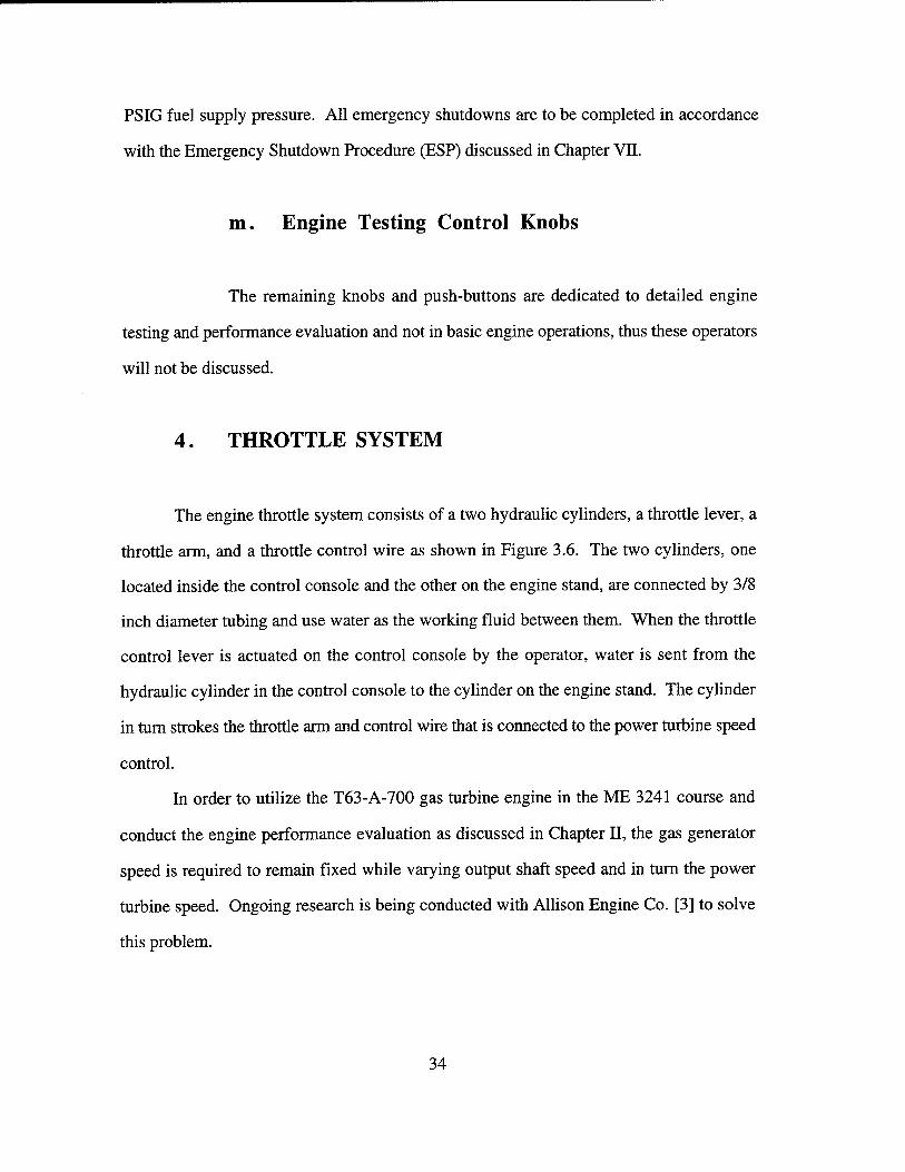
2. Front Support
Since the engine mounting brackets, delivered with the dyno engine stand were
intended for an internal combustion engine, an entire front support for the engine was
designed and fabricated from 6061-T6 aluminum. From a practical standpoint, the design
philosophy was to use the existing attachment points on the engine housing normally used
for mounting the engine in the helicopter airframe.
The front support uses a three point mounting approach as shown in Figure 3.9 and
3.10. Mounting pads are utilized on both sides, as well as, the bottom of the accessory
gear box. All supports are fastened together with grade 5 bolts for ease in disassembly for
shimming and addition of vibration isolation mounts. An additional, single base plate will
be added to the engine stand to facilitate shimming for more precise engine shaft alignment.
It is intended to utilize the gas turbine engine for further thesis research in the area of
vibration analysis, hence the importance of this capability. A detailed drawing with
dimensions is included in Appendix A.
39

3. Rear Support
After mounting of the gas turbine on the front support, it was determined that a
rearward eccentric moment was present that would place a large stress on the shafting
bearings. In order to eliminate this design deficiency, an engine rear support was designed
and fabricated as shown in Figure 3.9. This support, also made of aluminum, uses the
mounting point under the combuster outer casing just forward of the combuster drain. The
semicircular cutout provides a pass through for the engine drive shaft to the dynamometer.
A detailed drawing of the rear support with dimensions is also included in Appendix A.
4. Torque Plate
The Superflow 901-SF test system utilizes a system of strain gauges attached to the
power absorber to measure engine torque. This is quite suitable for internal combustion
engines which do not utilize a connection shaft between the engine crankshaft and the
power absorber drive spline. Since the gas turbine engine utilizes a connection shaft with
flexible couplings, this set up is not capable of providing an accurate torque measurement.
The purpose of the torque plate, which is shown in Figure 3.11, is to provide rigidity
between the gas turbine engine and the power absorber thereby making the strain gauge
configuration a workable means of measuring engine torque. A detailed drawing of the
torque plate with dimensions is shown in Appendix A.
40

I
CD
cx
|2
1000
800
600
400
200
2000 Atlf) 4000 SPEED
6000 8000 10000
Speed (rpm) Figure 3.1. Torque Capacity Comparison Curves for Engine and Power Absorption Unit. "From Ref. [5]."
41

-Vacuum Breaker
Engine Coolant Temperature \
Drain Valve
Eiectrical Connections
Throttle Actuator
bol Tray
Capacity Valve
Power Absorption Unit
Water Sump Tank
Water In
Pulse Damper'
Fuel Pump Fuel Return
Figure 3.2. SF-901 Dynamometer Engine Stand. "From Ref. [5]."
42

LOAD CONTROL "
MANUAL SERVO
■iSp^sii
Figure 3.3A. SF-901 Dynamometer Load Control. "From Ref. [5]."
Figure 3.3B. Dynamometer Power Absorber and Capacity Valve. "From Ref. [5]."
43

Figure 3.4. Superflow SF-901 Dynamometer Control Console.
44

SYSTEM WARNINGS T
WATER SUPPLY
DYNO PRIME
DATA RECORDED
ENGINE WARNINGS
OIL PRESSURE
WATER TEMP.
FUEL PRESSURE
OVERSPEED ^ -. ky^ %M H^ "i^iili^i^iiwptilK^Mi^
READY TO RECORD RECORDING
Figure 3.5. Control Console Engine Warning Lights and Digital Displays. "From Ref. [5]."
45

g**ifliir.iiiiillillljjjj|
Bali
ottle Arm
TMtOHU iCTtI*rOI jtfSWlLT
to^lix St*od ftnol
•cfc CO i«cur« *am*mb\Y ?rop«r lUfAMst «Lea «craw bot«« "uarrj«
^T— — ,■-■■.,. ?tltar\ / ^-ll ■■> - _,
"•r rn« cnxoecia actuator t* t«ir
Cue «way Ti.w of hov to <rpUMCOrY. I.MBA-C ta. ruab*rtnd portion at tft« b«llofr«a go«i cowcrd tu« Uli!* »•(or« actieMrwj co atand pan« I, 1U40 «to icrw bolts La eh* correct position bafsra «««UA? aaiaaaly.
■«llofrua, houdia?, aarf olstoa u«4 for ir-101 control Coaaolo T&rottl« t*Adl«.
Figure 3.6. Dynamometer Throttle System. "From Ref. [5]."
46

Figure 3.7. Output Drive Shaft.
47

817
X LU \ L Ü.
a > o O
0) > < 01
m NT3 I D.
0) Cfl aito uj ID CD DC
in • i^ en n
II (0 x>
o in
0O LU • OCtD LL^I
X UJ \ L LL
a > o
I O
D) > < 01
PI CL- OU)
OLOUJ
1 o ■H
—
in
c ^ ■""
N
■
L
1
o J
1 ■H
c o 'id +-> 'o X
W 05
3 <C
^ > ° -c •S Q
en ■£
_ 3 S o
fa c
O ° oo a>
<D O fa c«
#1
CD
o X^CDOE i mm 0)
00 "D II C0J (U ^ XDLL E
1 L> H
in x
X LL
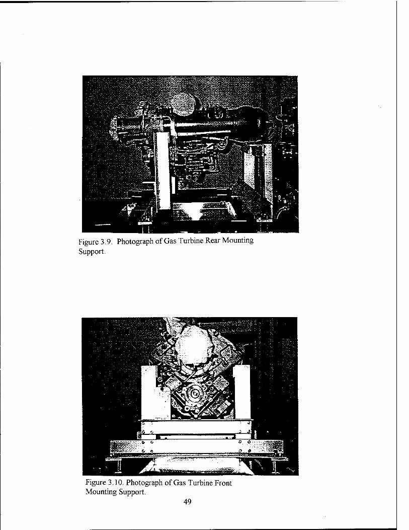
Figure 3.9. Photograph of Gas Turbine Rear Mounting Support.
Figure 3.10. Photograph of Gas Turbine Front Mounting Support.
49
Side View Front View
•L Figure 3.11. Dynamometer Torque Plate Adapter.
50

IV. GAS TURBINE TEST FACILITY
A. INTRODUCTION
The Marine Propulsion Laboratory is comprised of a gas turbine test cell, a Diesel
test cell, a laboratory preparation / instructional area, and an auxiliary machinery equipment
pad. The purpose of this chapter is to describe the physical layout of the Marine
Propulsion Laboratory and Gas Turbine Test Cell, as well as, discuss the auxiliary systems
which were designed to support gas turbine, Diesel, and dynamometer operations.
B. MARINE PROPULSION LABORATORY FLOOR PLAN
The Marine Propulsion Laboratory floor plan is shown in Figure 4.1. The
laboratory preparation / instructional area, which is approximately 900 square feet in area,
serves as a central location for gas turbine and Diesel documentation and also provides the
necessary student study areas and computer availability for detailed analysis. The work
area also contains the dynamometer control consoles and computer systems for both the
Diesel and gas turbine test cells. The operator is separated from the engine test cells by an
18 inch concrete block wall, double paned shatterproof windows, and two vapor proof
doors for safety considerations. Directly behind the Diesel and gas turbine test cells and
outside of the building structure is the auxiliary machinery equipment pad.
51

C. AUXILIARY MACHINERY EQUIPMENT PAD
The auxiliary machinery equipment pad, which is approximately 600 square feet in
area, is poured concrete and supports the water and fuel storage tanks, water and fuel oil
service pumps, water filtration elements, and the water system heat exchanger. A detailed
description of the auxiliary support equipment is discussed in Chapter V as part of the
auxiliary support system design. A photograph of the auxiliary machinery equipment pad
is shown in Figures 4.2 and 4.3. An equipment listing is contained in Appendix B.
D. GAS TURBINE TEST CELL
The gas turbine test cell is 30 FT X 15 FT X 9 FT and houses the gas turbine
engine and dynamometer, as well as, instrumentation racks, a flammable liquids locker,
and a fire extinguisher. Also enclosed within the cell are the piping runs for water and fuel,
connections for low pressure air, a city water connection, a fire extinguishing sprinkler
system in the ceiling, and electrical receptacles for 230 and 115 VAC. The concrete floor
contains a trench network used for running system piping and catching effluent liquid. The
piping trenches are 12 inches wide by 12 inches deep, and surround the engine and
dynamometer. The trenches also provide pass throughs for piping and electrical wiring
from the auxiliary machinery equipment pad and the laboratory preparation / instructional
area into the gas turbine test cell. In order to provide sufficient operator and student safety
along with adequate noise reduction, the test cell is enclosed by eighteen inch reinforced
concrete, and the observation window is made of double pane shatter proof glass. The
personnel entrance from laboratory preparation / instructional area is through double steel
52

doors which are vapor proof and add additional sound attenuation. The cell was designed
to achieve a 30 dB sound attenuation.
The air intake for the cell enters the building through louvers (Figure 4.4) located
directly above the auxiliary machinery equipment pad where the air ducting is turned ninety
degrees and enters the test cells through the ceiling. The gas turbine exhaust ducting is also
discharged through the ceiling of the cell and is routed through uptakes along the side of the
building. Figures 4.2 - 4.6 are photographs of the Marine Propulsion Laboratory at
various locations for added clarity.
53

PS
H6- OP -^
1Z> C
c
k^ "Sl ->
7T
o
Q
:< :K ;
ilJl 1 ;a ! :tc i 1
IS
:~ 0 if tiS :L
2 j{ S3 !S eä !i p j
cc < w
! f
!* r
lO
UV
<
< IO
V
P : ei : ei ; : •—
i ö -- r
Old l£il
o
;u; -
i n i
<
<
>< ei C H < 5 <
» 1 o o
o 5 g C
a U a •—, u: a
2^ jj — tu P H OÄ
Z < c
a
K) 5 S c
■c
E O
1 ^
u es
u. O
-O eö
5 iz>
3 O, O u.
c* _c eö
*■< s Oß
-^

Figure 4.2. Auxiliary Machinery Equipment Pad (Water Side),
55

Figure 4.3. Auxiliary Machinery Equipment Pad (Fuel Side).
56

Figure 4.4. Air Intake Louvers.
57

Figure 4.5. Exhaust Uptakes for Gas Turbine and Diesel Cells.
58

Figure 4.6. Gas Turbine Test Cell.
59

60
V. AUXILIARY SYSTEM DESIGN
A. INTRODUCTION
The purpose of this chapter is to discuss the design considerations and equipment
selection for the auxiliary support systems which support T63-A-700 gas turbine engine
and the Superflow 901-SF water brake dynamometer operations. Since the specifications
for the auxiliary equipment were written as part of the building construction contract and
not specifically for the T63-A-700 gas turbine and Superflow 901-SF dynamometer,
numerous modifications were made to existing equipment in order to meet design
requirements. The design criteria, system design, system schematics, and the actual
equipment installation for the water, fuel, air, oil, and electrical systems for the gas turbine
test facility will be discussed. A detailed equipment listing by system is enclosed in
Appendix C.
B. WATER SYSTEM
The support function for the water system is to provide water pressure resistance
and cooling water to the dynamometer power absorption unit's water brake impeller. A
schematic of the water system is shown in Figure 5.1.
61

1. Design Criteria
The design criteria as specified by Superflow Corporation in the dynamometer
manufacturer technical manual [Ref. 5: p.1.8-1.10] are summarized below:
* water flow requirement 1 GPM per 10 HP of engine load
* water supply pressure 35 PSIG min. / 60 PSIG max.
* dynamometer water discharge temperature 160 °F
* water quality (max. particulate size) 0.1 mm or 100 micron
As required by the Naval Postgraduate School in an effort to increase water
conservation, the water system must also be a closed system with minimal need for system
flushing and replenishment. The dynamometer manufacturer also specifies various water
quality requirements [Ref. 5: p. 1.10]. However, the water quality provided by the
California American Water Company [8] more than satisfies these requirements and no
water additives to maintain water quality were deemed necessary. An annual system flush
will also adequately maintain the required water quality for parameters such as hardness
and pH.
2. System Design
A 1,040 gallon steel water tank was installed along with two water supply pumps, a
radiator type heat exchanger, and the required supply and return piping (2 IN diameter)
from the auxiliary machinery equipment pad to the test cell. The first step of the water
62

system design was to determine if the equipment installed by the building contractor was
adequate to support gas turbine and dynamometer operations.
a. Water Storage Tank
A cylindrical, steel water storage tank is located on the auxiliary machinery
equipment pad. The tank, which is 12 FT long and 4 FT in diameter, has a capacity of
1,040 gallons. The tank has a 3 inch diameter suction line which is reduced to a 2 inch
diameter pipe prior to entering the filter. Within the suction line is a 3 inch fill connection.
A 1 inch diameter drain line with a 1 inch butterfly valve (CW-13) is also attached at the
base for draining. A 100 PSIG relief valve and a vent valve are also included to prevent
over pressurization and back pressure conditions. A 2 inch suction valve (CW-1) was
added to the system piping in order to facilitate isolation of an added filtration unit.
Cleaning of the filtration element requires isolation or draining of the water storage tank
prior to opening the filtration unit.
b. Supply Filtration Unit
In order to meet the maximum particulate size of 0.1 mm or 100 micron, a
filtration unit (50 micron) is installed in the 2 inch suction line prior to the supply pumps.
The filtration unit, which is pictured in Figure 5.2, is installed in order to augment the 100
micron filter located at dyno power absorber inlet. An added filter is necessary to prevent
rust and scale particles, which may dislodge from the sides of the steel tank and piping
during operation, from clogging the installed dynamometer filter and reducing the flow of
supply water to the power absorber. The filter also allows for system recirculation to
remove particulate from the tank if the system has been secured for long periods. Supply
63

water is discharged from the filter through 2 inch piping and a 2 inch butterfly suction cut
off valve (CW-2GT) into the inlet of the supply pump.
c. Supply Pumps
Since the maximum power rating for the T63-A-700 engine is 317 HP, a
maximum water flow rate of 32 GPM is needed at a minimum supply pressure of 35 PSIG
(81 FT H20). The two water supply pumps are centrifugal and are rated at 50 GPM at 125
FT H20 head (54 PSIG). Using the rated flow rate of 50 GPM (0.1114 FT3 /SEC) and
using an average kinematic viscosity of water as 9.30E-6 FT2 / SEC with a pipe diameter
of 2 ESI, a Reynolds number Rep ~ 91,500 is found. The piping from the supply pumps
to the dynamometer are schedule 40 steel with a nominal roughness to diameter ratio of
0.0009. From the Moody Diagram a friction coefficient, f = 0.02 is determined. The
head losses (hf) can be calculated from the equation:
hf = f(L/D)(V2/2g) (5.1)
where (L/D) is the pipe length to diameter ratio and V is the fluid velocity. The piping run
from the supply pumps to the dynamometer is approximately 50 FT in length and has
eight - 90 degree bends, two gate valves, and one angle lift check valve installed. The head
loss factors Ki (90 degree bend ), K2 (gate valve), and K3 (angle check valve), were
determined from tabulated sources [Ref. 9: p. 224-229] as 0.9, 0.19, and 5.0
respectively. The effective length, Le was calculated from the equation:
Le=K*D/f (5.2)
64
where K= 8K1 + 2K2 + K3 = 8(0.9) + 2(0.19) + (5.0) = 12.6. Thus, the effective
length, Le is found to be 105 FT. The total head loss from the supply pumps to
dynamometer is then calculated from Eq (5.1):
hf = 0.02 * ((105 + 50)/(2/12)) *(5.P/(2*32.17)) = 7.6 FT H20 or 3.3 PSIG
From the preceding head loss calculation, one can see that the head losses are insignificant
and the centrifugal water supply pumps satisfy both the flow and pressure requirements for
safe dynamometer operations.
The supply pumps are configured such that either pump can be used for the Diesel
or gas turbine cell in a series or a parallel configuration as shown in Figure 5.1. However,
the normal configuration for gas turbine dynamometer operation will be one supply pump
in operation with the other supply pump secured with the cross connect valve (CW-5)
closed.
d. Dynamometer Power Absorption Unit
Water discharged from the supply pump flows through a 2 inch angle swing
check valve (CW-3GT) and a 2 inch butterfly cut off valve (CW-4GT) into the gas turbine
test cell via the piping trench at the base of test cell wall. Located just inside of the test cell,
a dyno bypass line, a system unloader (CW-8GT) and a dyno supply line are configured in
parallel. The dyno bypass valve (CW-7GT), which is closed during dynamometer
operation, allows for system recirculation prior to placing the water system into service.
Supply water enters the dynamometer sump tank, which is discussed
Chapter III.B.6, through a float control valve into the segregated supply side of the sump
65
tank. The float control valve utilizes a float and arm assembly to secure the water supply to
the tank and prevent overflow during low demand conditions. A 1 inch boost line branches
off the supply line just prior to the float control valve. This boost line provides a
pressurized water supply to the power absorber during periods of rapidly increasing gas
turbine loading conditions; a feature needed to prevent engine overspeeds during conditions
of high water flow and low supply pressure. The design requirement for the water supply
pressure to be a minimum of 35 PSIG is for support of the boost feature. The supply
water in the dyno sump tank is open to the atmosphere and is drawn into the power
absorption unit by the water brake impeller through a 100 micron filter. The dyno power
absorber dissipates the gas turbine output power by transforming the output power into a
change in enthalpy. The elevated water temperature caused by the increase in enthalpy is
carried away from the power absorber by the water as it is discharged to the return side of
the segregated sump tank (power = water mass flow rate * change in enthalpy across the
power absorber).
e. Return Pump
Since the water is discharged from the power absorber to an open sump
tank, a return pump is required to pump the fluid from the dyno through the heat exchanger
and ultimately back to the storage tank. In order to determine the size of the return pump,
simple head loss calculations were done. The piping run from the dynamometer to the
storage tank is approximately 70 FT with twenty-one 90 degree bends, three gate valves,
one TEE, a heat exchanger, and one rapid expansion into the tank. The head loss factors
Ki (90 degree bend), K2 (gate valve), and K3 (TEE), were determined to be 0.9, 0.19,
and 1.8 respectively. Therefore, K= 2lKi + 3K2 + K3 = 21(0.9) + 3(0.19) + 1.8 =
21.3. From Eq 5.2, Le was found to be 178 FT. The pressure loss across the heat
66

exchanger, as specified by the manufacturer is 0.3 PSIG (0.69 FT H20) at this flow rate.
An elevation rise of 5 FT is also present because the piping discharges into the top of the
tank. The head loss due to the rapid expansion entering the storage tank, he, is found from
the equation:
he = (Vo-Ve)2/2g (5.3)
where Ve = 0. Thus, he = ( 5.11)2 / (2(32.17)) = 0.41 FT H20.
The total head loss was estimated from Eq 5.1 as :
hf = 0.02 * ((178 + 70)/(2/12)) *(5.P/(2*32.17)) + 0.41 + 0.69 + 5 = 18.1 FT H20 or
7.9 PSIG.
When selecting the return pump, the main design consideration was
choosing a pump with a larger designed flow rate than the supply pump. This is required
to ensure that no condition may exist which will allow the dyno sump tank to overflow
while the return pump is in operation. From these considerations a return pump rated at 75
GPM at 50 FT H20 head was selected (1.5 times the capacity of the supply pumps). In
order to eliminate the requirement for a foot valve, the selected return pump is also self
priming to 12 FT H20 and has an internal check valve to prevent backflow from the water
storage tank.. The return pump, which is a centrifugal pump, discharges the heated water
through a 2 inch globe valve (CW-9GT). A globe valve is used instead of a butterfly gate
valve in order to provide a means of throttling the return pump during low engine loading
conditions. Since the possibility exists that at low load demands on the dyno waterbrake
may occur which produce low effluent water flows, a centrifugal pump vice a positive
67

displacement pump was chosen. A centrifugal pump is more durable in such an
environment. A photograph of the return pump is presented as Figure 5.3.
f. Heat Exchanger
A principal design consideration of the water system is the capability of the
system to reject the heat added to the system by the power absorption unit. As specified by
Superflow Corporation [Ref. 5: p. 1.9], the water discharge temperature from the power
absorption must not exceed 160 °F. At temperatures greater than 160 °F, the power
absorption capability of the water brake may become erratic and produce an engine
overspeed. The capacity factor (overall heat transfer coefficient) of the heat exchanger is
1.30 HP/°F (55 BTU/MIN °F) which corresponds to a heat removal rate of 130 HP at
maximum water temperature when considering an ambient air temperature of 60 °F. When
one considers that the maximum power rating of the T63-A-700 gas turbine engine is
317 HP, it is evident that the run time for the gas turbine engine at high loading will be
limited by the cooling capacity of the heat exchanger and the thermal inertia of the system.
Since the primary use of the gas turbine test cell is student laboratory instruction, system
run times of approximately two hours are desired in order to allow sufficient time for data
collection at various power ratings. Since the requirement for multiple laboratory trials also
exists, the water cooling system must have the capability to cool the water temperature to
near ambient temperatures within two hours after securing the gas turbine. This capability
would allow two laboratory experiments to be run in a normal workday. With the present
configuration, a system run time for the gas turbine engine ranges from approximately 90
minutes at 200 HP to approximately 45 minutes at 300 HP which is less than the time
required to complete the necessary data collection for meaningful engine performance
68

evaluation. In an effort to overcome this shortcoming, an alternative solution to the present
heat exchanger configuration is investigated and presented in Chapter VI.
After the water temperature is reduced in the heat exchanger, the water is
returned to the storage tank through a return line located at the top of the tank. A 100 PSIG
relief valve (CW-14) is also installed in the piping above the tank which provides protection
from system and tank over pressurization.
3. Water System Alignment and Operation
The water supply system should be recirculated for approximately 40 minutes prior
to placing system into service if the system has been idle for more than 30 days. The 40
minute recirculation time constitutes two passes of the water supply through the 50 micron
supply filter. This will ensure sufficient filtering of sediment and rust particles from the
tank. Although the capability exists to run both supply pumps in a parallel or series
configuration, the recommended configuration is one supply pump aligned for operation
with the second secured with the cross connect (CW-5) closed. One supply pump is more
than adequate in capacity to provide a sufficient water supply to the dynamometer. A
complete description of the water system alignment is contained in the Standard Operational
Procedure (SOP MLOP) presented in Chapter VE.
C. FUEL OIL SERVICE SYSTEM
The function of the fuel oil service system, which is shown in Figure 5.4, is to
provide a continuous fuel supply of Diesel Fuel #2 to the T63-A-700 gas turbine engine.
The entire fuel oil service system is comprised of three subsystems: the auxiliary support
piping and equipment, the dynamometer fuel system, and the gas turbine fuel system.
69

Since the fuel oil service system must service both the Diesel and gas turbine test cells, the
fuel selected must be compatible with both the Diesel and gas turbine engines. After
consultation with technical representatives from both Detroit Diesel and Allison Gas
Turbine [6], it was decided that Diesel Fuel #2 would be used as the common fuel for both
engines. Although JP-4 is the primary fuel specified for use in the gas turbine engine,
Diesel Fuel #2 is an acceptable alternative since the gas turbine engine will be subjected to
relatively low operating hours (less than 100 hours) and in ambient conditions greater than
40 °F. Using Diesel Fuel #2 will, however, decrease hot section durability. If the gas
turbine test cell is in operation during periods when the ambient temperature is less than
50 °F, the fuel system should be placed into recirculation mode for 30 minutes prior to gas
turbine light off. During cold conditions, this practice will prevent paraffin separation that
may prevent good fuel atomization in the combustion chamber.
1. Design Criterion
The principal design criterion is to provide fuel to the T63-A-700 engine at a
minimum flow rate of 0.5 GPM and a pressure of 6 to 10 PSIG. This flow requirement is
derived from the specific fuel consumption, SFC of the engine at maximum power. At 317
HP, the SFC is 0.697 LB/HP-HR which corresponds to approximately 0.45 GPM. Since
the dynamometer was principally designed for internal combustion engines, the pressure
limitations are imposed by the capacity of the installed dynamometer fuel system
components. Even though the gas turbine engine utilizes its own duel element fuel pump,
bypassing of the dynamometer fuel system will disable the fuel flow measurement and
monitoring capability of the dynamometer control system.
70
2. System Design
During the construction of the Mechanical Engineering Building a fuel storage tank
was installed on the auxiliary machinery equipment pad along with two supply pumps and
the associated 3/4 inch supply and return piping to the test cell. The first phase in the
design of the fuel system was to determine the compatibility of the existing equipment,
provided by the contractor during the construction of the building, with the design
parameters needed for safe test cell operation.
a. Fuel Storage Tank
The above ground, concrete fuel oil storage tank, which has a 500 gallon
capacity, is 11 feet long, 4 feet wide and 3.5 feet high. The tank has a vent, a sampling
tube, a leak detector tube, as well as, the standard fill and drainage connections.
b. Fuel Supply Pumps
The two fuel supply pumps, which are piped in a parallel configuration,
take suction from the fuel oil storage tank through a common 3/4 inch swing check valve
(FOS-1) and their respective 3/4 inch butterfly cutoff valve (FOS-2GT). The fuel supply
pumps are positive displacement gear type pumps with an internal relief. The pumps are
rated at 3 GPM at 125 FT H20 head (54 PSIG). A 3/4 inch butterfly cross connect (FOS-
3) provides the capability of using either supply pump for service to both the Diesel and gas
turbine test cells. Prior to entering the test cell, the fuel flows through another 3/4 swing
check valve (FOS-4GT) and a butterfly cut off valve (FOS-5GT). Just inside the cell
71
another 3/4 inch butterfly cut off valve (FOS-6GT) is located in the piping trench to provide
double valve protection for a flammable liquid.
c. Flow Regulator (55 to 12 PSIG)
The maximum supply pressure to the dynamometer fuel system is 12 PSIG.
The maximum pressure limitation is imposed by an internal relief valve in the dynamometer
fuel system which is set at 12 PSIG. This relief valve is not of rigorous construction and is
not designed to be continually actuated as would occur when the system supply pumps,
which are rated at 125 FT head (54 PSIG), are placed in operation. In order to avoid
premature failure of the dynamometer fuel system relief valve, a flow regulator (FOS-7GT)
is piped into the system prior to the dynamometer fuel supply connection. This flow
regulator is adjustable from 0-25 PSIG with a minimum flow coefficient, CV=1.1. The
flow regulator, which is adjustable via a manual knob on the valve body, also has 1/4 inch
gauge ports on the inlet and discharge connections for monitoring. When adjusted for
discharge pressures of less than 12 PSIG, the flow regulator will also restrict the supply
flow rate to approximately 1 GPM. The positive displacement, gear driven supply pumps
have an internal relief which will prevent adverse pump stress and wear due to back
pressure induced by the flow regulator.
d. Adjustable Relief Valve
In order to provide additional protection from over pressurizing the
dynamometer fuel system, an adjustable relief valve is positioned at the discharge of the
flow regulator. The relief will be set at 12 PSIG and will bleed fuel to the return line in the
72

event that the flow regulator should fail. A picture of the flow regulator and relief valve are
shown in Figure 5.5.
e. Fuel Filters
The Diesel fuel, that has been reduced to approximately 1 GPM at 6-10
PSIG, is passed through two FRAM fuel filters which are of 10 and 5 micron respectively.
These additional fuel filters are installed to provide fuel filtering prior to entering the
dynamometer and gas turbine fuel system. These added fuel filters are necessary because
of the difficulty of changing the gas turbine 10 micron paper filter. The external fuel filters
also provide the capability of filtering, to an acceptable fuel oil quality prior to engine light
off by utilizing the fuel recirculation bypass valve (FOS-9GT).
f. Fuel Solenoid Operated Trip Valve
The primary means for emergency fuel shut off is the fuel solenoid trip
valve (FOS-10GT) located just prior to the engine fuel oil supply connection. The solenoid
is energized open by 12 VDC power from the storage batteries. Therefore, the fuel
solenoid valve is energized open when the dyno fuel pump is turned on and closed when
the dyno fuel pump is secured. This arrangement provides for positive fuel shut off by
simply securing the dyno fuel pump or the dyno control console and also provides the
additional safety feature by securing fuel to the gas turbine in the event electrical power loss
occurs within the building or system.
73

g. Return Line
A discharge connection is located on the dynamometer fuel system that
allows for discharge of unused fuel through the relief valve on the accumulator. This
discharge connection is attached to a 3/4 inch return line which exits the test cell and returns
to the storage tank. This return line is also used during fuel system recirculation via fuel
recirculation bypass valve as was discussed in Chapter V.2.e. A complete equipment
listing for the fuel system is contained in Appendix C.
3. Fuel System Alignment and Operation
The normal configuration for fuel system alignment to the gas turbine test cell is one
supply pump aligned for operation with the other supply pump secured and the cross
connect (FOS-3) closed. The flow regulator and adjustable relief are to be set at 10 and 12
PSIG respectively. The actual setting of the flow regulator may vary after system testing.
A complete description of the fuel system alignment for engine light off and fuel oil system
recirculation is contained in the Master Lightoff Procedure (MLOP) and the Fuel Oil
System Recirculation Procedure (FOSRP) in Chapter VII.
D. AIR SUPPLY AND VENTILATION SYSTEM
The support function of the air supply and ventilation system is two-fold. Firstly,
the system must provide an adequate engine air supply with a pressure drop within OEM
limits which will support gas turbine operations. Back pressure due to filtration and
ducting must be minimized. Secondly, the test cell must have sufficient exhaust ventilation
74

in order to prevent a temperature increase within the cell of more than 5.0 °F. This can be
accomplished if there is a sufficient secondary air or "through flow" from the intakes
through the module and out of the exhaust ducting.
1. Design Objectives
The principal design objective for the air supply and ventilation is to provide a
minimum air flow of 3,000 SCFM to the gas turbine compressor inlet. At maximum
power, the air flow rate through the gas turbine engine is 2,600 SCFM at 60 °F.
[Ref. 1: p. 4.20]
As recommended by the dynamometer manufacturer, the supply and exhaust
system should provide an air flow through the cell which produces a cell air exchange rate
of 8 to 10 times per minute. [Ref. 5: p. 1.10] An air exchange rate of this magnitude will
prevent unpredictable fluctuations in space temperatures that may affect the performance of
instrumentation equipment. This design objective, however, has been determined to be
unachievable from flow rate estimates. Additional research is being conducted using
exhaust eductors to optimize secondary air flow, and cost estimates are being investigated
for an additional electrical cooling fan to be installed in the building exhaust ducting. After
sufficient engine testing and test cell temperature measurement, a decision will be made.
75

2. System Design
a. Supply Ducting
The air supply ducting provided by the contractors during construction of
the Mechanical Engineering Building positioned the air intakes above the auxiliary
machinery equipment pad external to the test cell. Outside air enters the supply ducting
through louvers located on the building exterior as shown in Figure 4.4. Just inside the
louvers is a 1/2 inch mesh foreign object debris screen and shutters. The shutters are a fire
prevention and control device which automatically close in the event of a fire. The shutters
are manually spring loaded open and are released if fire detectors sense a fire thereby
sealing off air supply to the cell. This feature, however, was not completed properly by the
building contractor and is being added to the contractor discrepancy package. After
entering the shutters, the supply air travels approximately 5 feet horizontally through air
intake silencers above the gas turbine test cell. The supply air is then turned 90 degrees
downward through a 48 inch X 48 inch opening in the test cell ceiling.
In order to provide the capability to direct air flow, as well as, the ability to
close-off the intake when the cell is not operational, adjustable shutters are mounted over
the opening which are mechanically linked to an electrical shutter motor. The shutter
motors are powered from a 230 VAC breaker located near the control console in the remote
breaker panel.
Positioned above the ceiling shutters are four - 24 inch X 24 inch high
performance air filters which provide filtration of particles above three microns at 95%
efficiency. A minimal pressure drop of less than 1 inch of water is expected when the
filters are in a clean condition.
76

b. Inlet Plenum
The gas turbine engine compressor inlet is attached to an inlet plenum
chamber which is fabricated from 1/4 inch clear Plexiglas and aluminum supports. The
plenum is made of clear Plexiglas in order to allow observation of the air flow profile into
the compressor. On the intake side of the plenum, two air flow turbines are mounted
which are used to measure the air flow rate into the compressor. Since each air turbine is
rated to measure only 1,200 SCFM, the turbines are wired in parallel which increases the
measurement range to 2,400 SCFM. Although the maximum air flow rate of the gas
turbine is approximately 2,600 SCFM, this range is sufficient for most gas turbine
operations. The manufacturer suggests that each air flow turbine has the capability to
measure air flows of up to 1,500 SCFM each without altering their calibration.
Inside the plenum chamber, a system of screens and baffle plates are used to
direct the air flow into the compressor inlet. These screens and plates are used to break up
any vortices or flow disturbances produced by the flow turbines which may cause a
compressor stall. Once through the flow turbines, the supply air encounters a 20-mesh
screen followed by an 18-mesh screen. Next, the air flows through an aluminum baffle
plate with 1 inch holes followed by another plate with 1/2 inch holes. Both plates are 48%
open. From the last baffle plate the air exits the inlet plenum through a calibrated
compressor bellmouth into the inlet guide vanes of the compressor.
c. Exhaust Ducting
In order to achieve the aforementioned criterion of a high air exchange rate,
an eductor system is being designed as part of another thesis project. This ducting will be
77

fabricated from 316 stainless steel and will attach to the exhaust ducts on the gas turbine
engine. A separate 8 inch vertical duct will be used for each of the dual exhaust ducts from
the engine and will direct the exhaust upward toward the 36 inch by 36 inch exhaust
opening in the test cell ceiling. The nozzles will be sized and fitted approximately 12 inches
below this opening in order to produce the desired air eductor effect. The eductor nozzles
will be both variable in height and in diameter for experimentation and flow optimization.
Once the exhaust air enters the ceiling opening, it is turned 90 degrees and
directed horizontally above the ceiling to the exterior of the building. After exiting the
building, the flow is again turned 90 degrees upward by circular exhaust ducting. This
ducting, which runs up the side of the building to the roof where it is capped, is also made
of 304 stainless steel. A deflector shield will be installed along with exhaust flow
measuring devices for mass flow rate and exhaust gas temperature. The exhaust uptakes
are pictured in Figure 4.5.
d. Auxiliary Ventilation System
As part of the building construction, a 800 SCFM supply fan and ducting is
installed on the intake side of the cell. Also included is a 800 SCFM exhaust fan at the
exhaust side of the cell. This system can be used to ventilate the test cell when the gas
turbine engine is secured. The supply and exhaust fans are controlled by a thermostat
switch just outside the entrance doors to the test cell.
E. LUBE OIL STORAGE AND CONDITIONING SYSTEM
The T63-A-700 gas turbine engine utilizes a circulating dry sump system with
supply and scavenge elements enclosed inside the engine's accessory gear box. Therefore,
78

the support function of the lubrication storage and conditioning system is to provide a
means of storing and cooling of the MIL-L-23699 lubricating oil. A more detailed
discussion of the internal components within the engine lubrication system is presented in
Chapter II, Section C.
1. Design Criteria
There are three main design requirements of the lubrication oil storage and
conditioning system. The system must have the capacity to store a minimum of six quarts
of lubricating oil. Secondly, the system must be able to maintain the system oil temperature
below 225 °F. Lastly, the dynamometer test system must be successfully instrumented for
proper monitoring of system pressure and temperature.
2. System Design
The design philosophy for the lubrication system was simple; utilize
existing airframe components and make the necessary modifications for use with the
dynamometer test system. A complete listing of these parts is contained in Appendix C.
a. Storage Tank
The oil storage tank, which constructed from sheet metal, is mounted near
the dynamometer test stand. The tank has a 5 gallon capacity and connections for fill,
supply, and return. A vented fill cap is also provided to prevent system or tank over
pressurization. The tank will have a dipstick installed with a low mark placed at the 4
gallon level.
79

b. External System Piping
The engine's accessory gearbox provides connections for both the supply
and return lines. A supply line, which is connected from the storage tank to the front of the
accessory gearbox, transports supply oil from the storage tank to the engine supply
elements. A discharge line, connected to the front of the accessory gearbox, returns the
discharged oil back to the storage tank via an oil cooler. The supply and pressure sensing
piping is made form 3/8 inch Teflon flexible hose with a 304 stainless steel overbraid. The
discharge piping is made of the same material and is 1/2 inch diameter.
c. Oil Cooler
The oil cooler is a radiator, fin type heat exchanger which utilizes forced air
from a gear driven fan to cool the lubrication oil. In the airframe, the gear driven fan is
powered by shafting from the tail rotor transmission assembly. This configuration is not
possible since the tail rotor connection is used for the main drive shafting from the engine
to the dynamometer power absorber. In order to overcome this problem, an electric fan
will be mounted behind the oil cooler for increased cooling effectiveness in order to provide
the required forced air flow through the fin assembly.
d. Oil Pressure and Temperature Monitoring
System
The Superflow dynamometer test system provides the capability to monitor
system oil pressure, oil supply temperature, and oil discharge temperature. Oil pressure
80
monitoring is accomplished by the dynamometer test system via a sensing line between the
pressure connection on the front of the accessory gearbox and the test stand instrumentation
rack. From the instrumentation rack, another sensing line routes fluid pressure to a
mechanical gauge on the dynamometer control console. The mechanical gauge has range of
0-160 PSIG which is sufficient to monitor normal system pressure (90-110 PSIG).
However, the low oil pressure warning light, which is presently set at 15 PSIG must be
reset at 50 PSIG; the minimum safe operating pressure for the engine. [Ref. 1: p. 1-4A]
An emergency trip device will be added to the system which will secure power to the fuel
solenoid trip valves if the oil pressure drops below 50 PSIG after the engine reaches idle
speed. This additional safety feature, which is to be added as part of the instrumentation
package, will provide an automated quick response to a low oil pressure condition and
prevent an irreparable engine failure.
The dynamometer control system provides two thermocouples which
provide the capability of measuring oil supply and discharge temperatures. A readout of
the oil temperatures may be read from on the left most analog meter by selection of either
OIL IN or OIL OUT on the TEMPERATURE METER knob. Since the maximum design
operating oil temperature is 225 °F, the meter scale, which is 0-300 °F, provides the
necessary range for proper monitoring of the system oil temperatures.
F. ELECTRICAL SYSTEM
The support function for the electrical system is to provide 230 and 115 VAC single
phase power, as well as, 24 and 12 VDC power to the auxiliary support equipment,
dynamometer control console, dynamometer engine stand, and the T63-A-700 gas turbine
electrical system.
81
As part of the construction the Mechanical Engineering Building, 230 and 115 VAC
are installed in the gas turbine test cell. A Westinghouse series distribution panel is located
on the auxiliary machinery equipment pad as shown in Figure 5.6. Initially, the
distribution panel contained local breaker motor control boxes for the fuel oil supply
pumps, lubrication oil supply pumps, and the cooling system heat exchangers. Two
additional breaker motor control boxes have been added due to the addition of cooling
water return pumps for both the Diesel and gas turbine test cells.
As discussed above, the essential alternating current power supply system was
provided for the gas turbine test cell during building construction. However, the required
direct current power supply source and distribution were not included. The remainder of
this chapter is devoted to a discussion of the direct current power distribution design, as
well as, the modifications for remote operation of the auxiliary machinery equipment from
the dynamometer control console operating area.
1. Design Criteria
The design objectives of the electrical system are two-fold. Firstly, a suitable direct
current power distribution is required to support the T63-A-700 electrical system and the
instrumentation and support equipment on the dynamometer engine stand. Secondly, a
centrally located power panel for the auxiliary support equipment requiring alternating
current power is desired for straight-forward test cell operation.
2. System Design
The gas turbine engine, requires 24 VDC power to the engine starter / generator and
exciter while the dynamometer engine stand utilizes 12 VDC power. However, both are
82

powered by two-12 Volt batteries wired in a series configuration. A complete equipment
listing is contained in Appendix C.
a. Storage Batteries
Since the gas turbine engine starter / generator utilizes 24 VDC power, two-
12 Volt (800 cold cranking AMP) automotive batteries are wired in a series configuration.
The batteries are mounted on the dynamometer engine stand. A 20/2 AMP 12 Volt battery
charger is also provided for battery charging.
b. Starter / Generator
The engine starter / generator is energized by depressing the STARTER
push-button on the dynamometer control console. Depressing the push-button places the
starter / generator relay, which is mounted on the dyno test stand, into the start
configuration thereby allowing electric current to flow from the storage batteries to the
starter / generator. After the gas generator (Nl) reaches idle speed (30,000-32,000 RPM),
the STARTER push-button is released and the starter generator relay returns to the
generator configuration. When in this mode the generator recharges the storage batteries
via a voltage regulator that is also mounted on the test stand. A complete description of the
gas turbine electrical system is discussed in Chapter n, Section C.
83

c. 12 Volt Dynamometer Engine Stand Power
Switch
In order to provide 12 VDC power to the dyno engine stand, fuel pump, as
well as, the fuel oil shutoff solenoid, a 12 Volt relay switch is connected to one 12 Volt
battery. When the FUEL PUMP switch on the dyno control is turned ON, the 12 Volt
relay is closed and a 12 VDC current flows to the fuel pump and the solenoid operated fuel
trip. The electrical power energizes the fuel oil shutoff solenoid valve open simultaneously
with the starting of dyno fuel pump. The solenoid is wired in series with the fuel pump
and can only be energized open when the fuel pump is turned on.
d. Fuel Oil Solenoid Operated Shutoff Valve
The fuel oil solenoid operated shutoff valve is an added safety feature which
provides a more positive control of fuel flow to the gas turbine engine. By wiring the fuel
trip such that it is electrically energized open when the dyno fuel pump is turned on, the
fuel pump switch can be used as the primary means of casualty control. The first
immediate action in the Emergency Shutdown Procedure (SOP ESP) contained in Chapter
VII, is securing the dyno fuel pump.
e. Remote Breaker Panel
Although the alternating current electrical distribution provided by the
building contractor was adequate to support test cell operations, the system was not
configured for remote operation. Therefore, modifications to the power distribution were
84

deemed necessary to facilitate remote operation of all auxiliary machinery by a single
operator.
In order to achieve this goal, a remote power panel is installed near the dyno control
console. Remote breakers for the fuel oil supply pump, cooling water supply pump, heat
exchanger, cooling water return pump, and intake shutter motor are contained within the
panel. A spare breaker is also provided for system expansion. During system alignment
prior to engine light off, the Master Light Off Procedure (MLOP) requires placing of the
local breaker motor control box, which is located inside the distribution panel on the
auxiliary equipment pad, into the AUTO position. Positioning of the three way (HAND-
OFF-AUTO) switch in the AUTO position, passes breaker control to remote power panel.
If the breaker is placed in the HAND position, the equipment motors may be started from
the START-STOP switches in the auxiliary machinery pad's local power panel. This
electrical distribution panel configuration allows versatility in system operation and in the
performance of maintenance procedures.
85

98
o
B
6 I 03

Figure 5.2. Cooling Water System Filtration Unit.
87

Figure 5.3. Cooling Water System Return Pump.
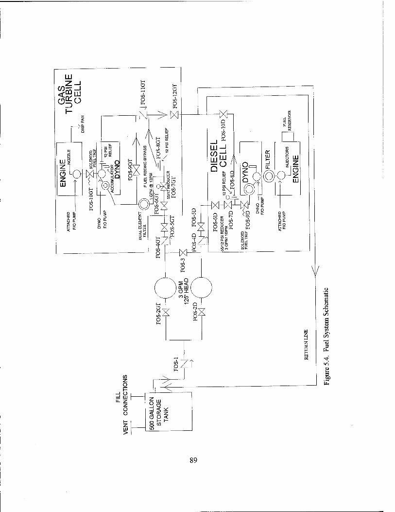
LU Z—I
<£9UJ «*0
5 Öd O
-NT
5 00 o
CO
o
=! UJ h- i ■ —» '
O Ü
LU >
° o _i < < a o o
HXh o o
i
O
UJ CO LU
^2
A
6g
O
53
DO. Ul S I 3
V
7'
4>
89
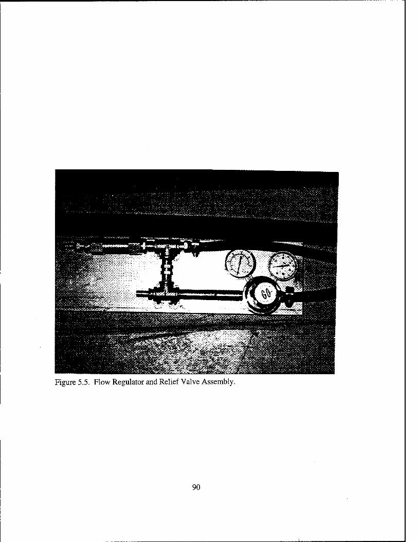
Figure 5.5. Row Regulator and Relief Valve Assembly.
90

Figure 5.6. Auxiliary Machinery Equipment Pad Local Power Panel.
91

92
VI. HEAT EXCHANGER ALTERNATIVE STUDY
A. INTRODUCTION
The heat exchanger, as provided is inadequate because it does not provide sufficient
cooling for the dynamometer water system (Figure 5.1) at steady state for loads greater
than 150 HP. The heat exchanger, which is pictured in Figure 6.1, is an air cooled radiator
type exchanger that provides forced air flow through a finned core.
In order to ensure safe operation, the dynamometer manufacturer specifies the
maximum discharge water temperature from the power absorber / water brake must not
exceed 160 °F. The capacity factor (overall heat transfer coefficient) of the heat exchanger
is 1.30 HP/°F (55 BTU/MIN °F) which corresponds to a heat removal rate of 130 HP at
maximum water temperature when considering an ambient air temperature of 60 °F. When
one considers that the maximum power rating of the T63-A-700 gas turbine engine is
317 HP, it is evident that the run time for the gas turbine engine at high loading will be
limited by the cooling capacity of the heat exchanger and the thermal inertia of the system.
The purpose of this chapter is to report on a study that was conducted to assess the
capabilities of the present cooling system and to investigate alternatives that will permit the
system to operate in the steady state at full power. A transient analysis, utilizing a
computer simulation, was used as a basis for the study.
93

B. ANALYSIS
1. Design Considerations
The principal design consideration for the dynamometer water cooling system is to
provide sufficient system cooling for the dynamometer water brake. As specified by the
dynamometer manufacturer [Ref. 5: p. 1.9], the water discharge temperature from the
power absorption unit must not exceed 160 °F. At temperatures greater than 160 °F, the
power absorption capability of the water brake may become erratic and produce an engine
overspeed condition. The primary use of the gas turbine test cell is for student laboratory
instruction. Run times of approximately two hours are anticipated. Since the requirement
for multiple laboratory trials exists, the water cooling system must also have the capability
to cool the water temperature to near ambient temperatures within two hours after securing
the gas turbine. The heat exchanger must be able to sustain two hours of gas turbine run
time at various power settings and be able to cool the water back to near ambient conditions
within two hours after engine testing.
94

2. System Model
A simplified model of the water cooling system used in the transient analysis and
computer simulation is shown in Figure 6.2. The pertinent system parameters, which are
discussed in detail in Chapter V.A, utilized in this analysis are shown below:
* water storage tank capacity
* supply pump rating
* dyno discharge rating
* return pump rating
* heat exchanger capacity factor
* ambient air temperature
* atmospheric pressure
* tank diameter
* tank length
1,040 gallons
50 GPM @ 125 FT head
1 GAL per 10 HP of load
75 GPM @ 75 FT head
1.30HP/°F
60 °F
15PSIA
4FT
12 FT
Since the objective of this analysis is to determine an approximate time dependent
water temperature profile at the dynamometer power absorber discharge, the following
simplifying assumptions are made:
* The power absorber dissipates the gas turbine output power by
transforming the output power a change in enthalpy. The elevated water temperature
caused by the increase in enthalpy is carried away from the power absorber by the water as
it is discharged to the return side of the segregated sump tank by the water brake impeller.
95

* Since the tank and piping, which are located on the auxiliaries equipment
pad external to the building, are mostly shaded, radiative heating of the water tank and
system piping is neglected. Radiative cooling from the tank and external piping is also
negligible (less than 1 HP).
* Free convection heat transfer from the water storage tank is modeled as
cross-flow over a cylinder. End effects from the cylinder ends are also neglected for a
conservative estimate.
3. Thermodynamic Analysis
The thermodynamic state points for the system analysis area are also shown
in Figure 6.2. The MATLAB computer code utilized in the transient conduction analysis is
contained in Appendix D.
State points 5-1
Since ambient temperature (Tamb) is assumed to be 60 °F, the initial water
temperature in the tank (T5) is also assumed to be 60 °F. The water enthalpy in the tank
(h5) is found from steam tables with the entering arguments of pressure (P5) and
temperature (T5). Secondly, the enthalpy change across the supply pump is considered
negligible over the pressure change from 15-70 PSIA for sub cooled water. Thus,
hi=h5 andTi=T5. (6.i)
96

State points 1-2
Since all energy dissipated by the power absorber is assumed to be
transferred as heat to the water discharged by the water brake impeller,
Ql2 = HP, (6.2)
where HP is the power output from the gas turbine engine.
The dyno enthalpy discharge (h2) is calculated from the equation
h2 = (Ql2 + Mdot*hi)/Mdot, (6.3)
where Mdot is the mass flow rate discharged by the power absorber. The temperature (T2)
is found by interpolation from steam tables using I12 and P2.
State points 2-3
Neglecting enthalpy and temperature changes across the return pump for
sub cooled water yields
h3 = h2 and T3 = T2. (6.4)
97

State points 3-4
The heat removed from the water system by the heat exchanger (Q34) is
calculated from
Q34 = Cf * (T3 - Tamb), (6.5)
where Cf is the heat exchanger capacity factor. The heat exchanger discharge enthalpy is
found from
I14 = (Mdot * h3 - Q34) / Mdot (6.6)
The temperature (T4) is then found by interpolation from the steam tables as before.
State points 4-5
The water temperature change in the storage tank is a combination of two factors:
the mixing of warm water from the heat exchanger with the water stored in the tank and
heat removed by free convection from the tank to the surroundings. The mass fraction of
water (frc) returned to the tank is found from
frc = Vdot*time/Ftank, (6.7)
where Vdot is the volumetric flow rate and Vtank is the volume of the storage tank.
98

The bulk enthalpy of the tank (htank) is then found from
htank = [h4 * frc + hpre4]/ (1 + frc) (6.8)
which may be simplified for frc ~ 0 to
htank = h4 * frc + (1-frc) * hpre4, (6.9)
where hpre4 is the tank enthalpy prior to mixing, in other words, the enthalpy from the prior
time increment.
The free convection coefficient (Hfc) for a cylinder is approximated from the
equation
Hfc = Kair/d * {0.6 + (.387Rad 1/6)/ [ 1 +(.559 / Pr )9/16]8/27 }2; (6.10)
where Kak is the thermoconductivity of air
d is the diameter of the storage tank
Rad is the dimensionless Rayleigh number
Pr is the dimensionless Prandtl number
The heat removed from the storage tank by free convection to the surroundings
(Q45) is governed by
Q45 = Hfc * tank surface area * (Ttank - Tamb)- (6.11)
99
The supply pump inlet enthalpy (I15) is then calculated from
hs = (Mdot * htank - Q45) / Mdot, (6.12)
and finally, T5 is found by interpolation from the steam tables.
4. Computer Program Description
The computer program is written in MATLAB. The computer program utilizes a
time marching scheme (one minute increments) and is essentially a repetition of the
thermodynamic analysis described above for each step. The objectives of the computer
code are to obtain graphs of water temperature at the dynamometer inlet, dynamometer
discharge, and heat exchanger discharge verses time, as well as, engine power, heat
removed by the heat exchanger, and heat removed by free convection verses time. The
overall aim is to find a good estimate of the time required for the dyno discharge
temperature to reach 160 °F at various engine loadings and a configuration which will
allow for full power operation in the steady state.
5. Results from the Transient Analysis for the Existing
Cooling System Configuration
Using the MATLAB computer code, graphs of water temperature verses time
(Figures 6.3 - 6.5) were generated for gas turbine power ratings of 200, 250, and 300 HP
respectively. Since the dynamometer power absorber water discharge temperature of
160 °F is the limiting parameter, the maximum system run time corresponds to this
temperature. From these figures, one can see that the heat removal capacity of the present
100

configuration as installed is inadequate and does not provide for sufficient gas turbine
engine run time to fulfill the student laboratory requirements. Also from these figures, it is
observed that the system run time for the gas turbine engine ranges from approximately 90
minutes at 200 HP to approximately 45 minutes at 300 HP which is less than the time
required to complete the necessary data collection for meaningful engine performance
evaluation. The heat exchanger ineffectiveness at low temperature differences between the
water temperature at the heat exchanger inlet and the ambient air temperature is apparent
when observing the rapid temperature increase in the first minutes of gas turbine operation.
Figure 6.6 is a graph of heat rate verses time which shows the inability of the heat
exchanger to match the heat addition by the dyno water brake. Also shown in this figure is
the insignificant role that free convection plays in this configuration. The average free
convection heat transfer coefficient is only the order of 0.5 to 0.9 BTU/ HR FT2 °F (3.0 to
5.0 W/M2 K). Figure 6.7 shows the time history of system cooling with the gas turbine
secured after reaching the maximum dynamometer discharge temperature of 160 °F. The
approximate temperature difference across the dynamometer is approximately 50 °F, thus
the water tank temperature / dyno inlet temperature is approximately 110 °F at maximum
dyno discharge temperature. From Figure 6.7, it is observed that system cooling time for
the water supply to reach near ambient temperatures is over five hours which does not
facilitate versatility in conducting more than one laboratory in a normal work day.
The above results clearly demonstrate the inability of the present cooling system
configuration to satisfy the above design criteria. Therefore, the need for an alternative
design of the water cooling system is warranted in order to provide the necessary versatility
required in performing meaningful engine testing and research.
101

6. Results from the Transient Analysis for Cooling
System Alternatives
The principal considerations in choosing an alternative for the present system are
cost and the capability to successfully modify the system with minimal change to the
present piping and pump configurations. As required by the Naval Postgraduate School in
an effort to increase water conservation, the system must be a closed system. Therefore,
alternatives such as an evaporative cooler and water make-up systems were not considered.
The three alternatives considered in this study were the addition of a make-up pump to
increase the mass flow rate through the heat exchanger, replacement of the present heat
exchanger with one of higher capacity, and thirdly, addition of another water storage tank.
Since the water flow rate through the heat exchanger is controlled by the water
discharged by the water brake impeller, which is rated at 1 GPM / 10 HP, the maximum
flow rate through the heat exchanger is 30 GPM at 300 HP. The minimum allowable flow
rate through the heat exchanger for optimum heat removal is 30 GPM. For all flow rates
below this level, the capacity factor must be derated by 10% as was done in the simulations
that produced Figures 6.3 - 6.6. In order to avoid derating the capacity factor, a make-up
pump (5 GPM) as shown in Figure 6.8 is implemented to boost the flow rate for power
ratings less than 300 HP. Figure 6.9 shows the results with the implementation of the
make-up pump alternative. After comparing Figure 6.4 with Figure 6.9, one sees the
addition of the make-up pump adds only approximately five minutes to the run time of the
system. The problem with this solution is the loss of the high temperature gradient in the
heat exchanger with the ambient air temperature caused by the mixing of the cooler water
from the storage tank with the warmer water from the dyno discharge which results in an
overall lower average temperature. Heat exchangers, as discussed in section 5, have
102

greater heat rejection capabilities at higher temperature differences. This factor diminishes
the 10% increase in capacity offered by this alternative.
The second alternative considered was increasing the size of the heat exchanger and
its capacity factor. Figure 6.10 shows the results of the simulation with a heat exchanger
that has a capacity factor which is 1.5 times larger. This change does increase the run time
to approximately 90 minutes but still does not achieve the design goal of two hours.
However, increasing the capacity factor to 2.6 HP/°F (110 BTU/MIN °F), which is twice
the capacity of the present heat exchanger, does meet the run time criterion as shown in
Figures 6.11 and 6.12. From Figure 6.13, which is a graph of heat removal rate verses
time, one sees the desired, near steady state, operating capability of the heat exchanger at
the maximum temperature condition after three hours of gas turbine operation. The goal of
successful heat exchanger design is the ability to reject as much heat as is added to the
system when at the maximum temperature condition. Thus, the heat exchanger is operating
efficiently at a maximum temperature gradient with the ambient air and the water
temperature is no longer increasing. Figure 6.14 shows the capability of the heat
exchanger to cool the system back to near ambient temperatures quickly, thereby permitting
the operation of the laboratory again within two hours of securing the gas turbine from
operation.
The last alternative considered was doubling the tank storage capacity from 1,040
gallons to 2,080 gallons. Doubling the tank size allows for approximately two hours of
gas turbine operation at 250 HP which is an improvement but does not produce the desired
results.
103

C. CONCLUSIONS AND RECOMMENDATIONS
Increasing this size of the heat exchanger from a 26D1Q to twice the capacity factor
of 2.6 HP/ °F (110 BTU/MIN °F) as provided by the 66D2Q heat exchanger manufactured
by Young Radiator, as shown in the specification sheet contained in Appendix D, can be
accomplished with no piping changes for approximately $2,500. This change meets all the
required design criteria, and the modification may be completed in less than one day after
receipt of the heat exchanger. After considering the above factors, this study clearly shows
that replacing the existing 26D1Q with the 66D2Q heat exchanger is both the simplest and
most cost effective alternative to the present configuration. Therefore, it is recommended
that the present 26D1Q be traded in for a 66D2Q at a net cost of $2,500 as quoted by [11].
104

Figure 6.1. Photograph of Water System Heat Exchanger
105

901
Ü
X W
gcto
3
CO o
s PL,
<H
■Tf
D (N W i-H
a \ /
O
? T 1
Q
C/3
o
-o o s £ to (/5
e >. -o o
JS H
u 3

WATER TEMPERATURE VS TIME @ 200 HP 200
180
160
LU K140
£ LU 1120 LU
100
80
60
D r"NO DIJ iCH./HX 3ER INI .ET TEN P
/ HX< 5ER DIS 5H-TSÖ P
/vt\ JO INLE TTEMP
20 40 60 80 100 120 TIME (MIN)
140 160 180 200
Figure 6.3. Temperature Curves Verses Time for an Engine Load of 200 HP with the Existing, Installed Equipment Configuration.
107

WATER TEMPERATURE VS TIME @ 250 HP 200
180
160
LU a: 140 Z>
LU ^120 LU I-
100
80
60 0 20 40 60 80 100 120 140 160 180 200
TIME (MIN)
Figure 6.4. Temperature Curves Verses Time for an Engine Load of 250 HP with the Existing, Installed Equipment Configuration.
DY MO DISC IH./HXG ER INLE TTEMF i -^
/ HXfiF Rni««* JTFMP
/ /
/
s
0YNO If JLETTE MP
108
200
180
160
UJ a: 140
& UJ 1120 at
100
WATER TEMPERATURE VS TIME @ 300 HP
DYNi } DISCh ./HXGE RINLE1 TEMP
/
/ / . IXGER^l )ISCH T EMP
/
/
/)
*
/DYN D INLET TEMP
0 20 40 60 80 100 120 140 160 180 200 TIME (MIN)
Figure 6.5. Temperature Curves Verses Time for an Engine Load of 300 HP with the Existing, Installed Equipment Configuration.
109

300
250
200 a. x Hi I- g150
< x
100
HEAT RATE VS TIME @ 250 HP
ENGINE HEAT RATE
HEAT EXCHANGER REJEC
FREE CONVECTION HEAT RATE
20 40 60 TIME (MIN)
80 100 120
Figure 6.6. Engine Heat Addition Verses Time for an Engine Load of 250 HP with the Existing, Installed Equipment Configuration.
110

WATER TEMPERATURE VS TIME W/DYNO SECURED (EXISTING CONFIGURATION)
110r
105
100
^^^ 95 u. '**** LU
3 90 I-
£ 111 Q. 85
LU
80
75
70
65
\\
\\ HXGER DISCH TEMP
\ \ \
V NX DYNC i INLET TEMF » ^^
^^
50 100 150 TIME (MIN)
200 250 300
Figure 6.7. Temperature Curves Verses Time with the Dynamometer Secured with the Existing, Installed Equipment Configuration.
Ill

zu
s
Tj-
1 PH
CO PH
GO
^
m
co OH
O
C i—(
I 3
PH
o. I
■a
e o
«SO
J3
'S s s « C/5
& O
O je H 00 vd u u
§> ix«
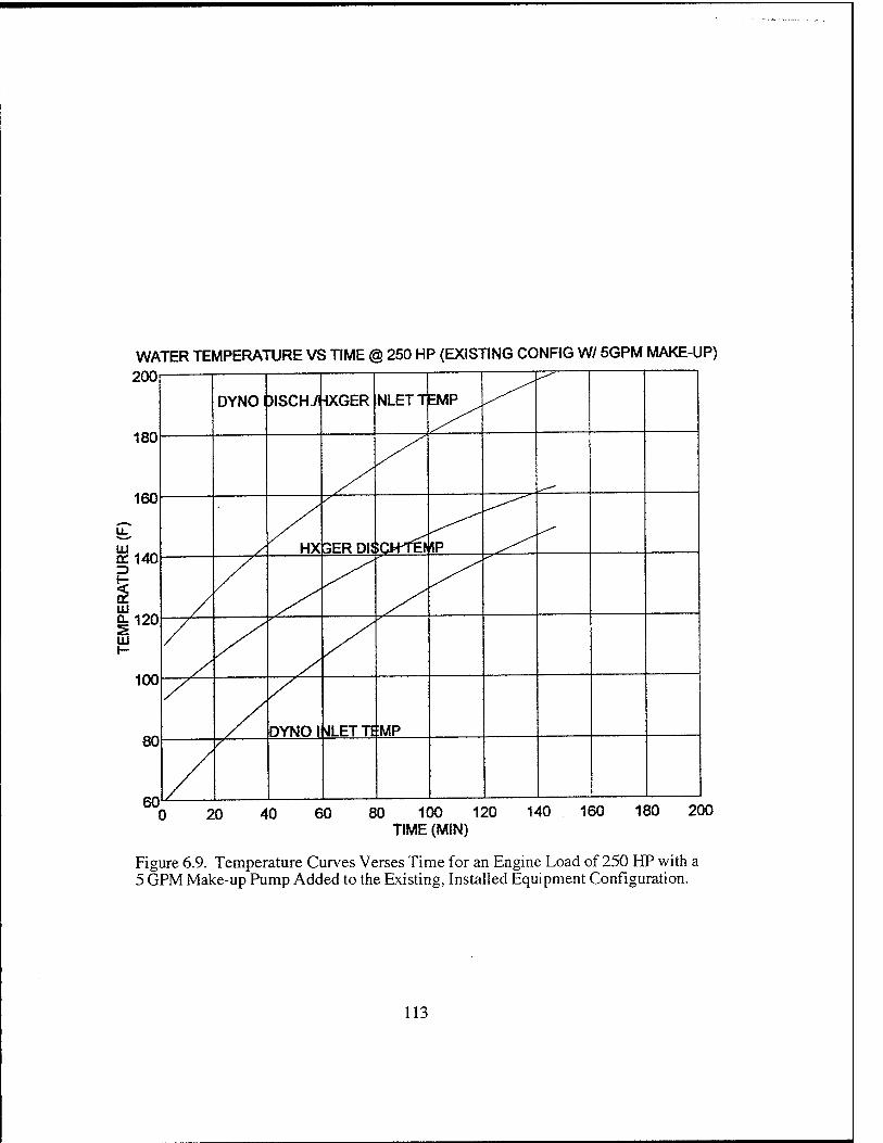
WATER TEMPERATURE VS TIME @ 250 HP (EXISTING CONFIG W/ 5GPM MAKE-UP)
2UU
180
160
LU a: 140 z>
1 Ui |120 LU
100
80
DYNOI )ISCH./i HXGER NLETT EMP
y /
/ HX GER Dli IOPTB rtP
/
/
/
DYNOI ALETTE :MP
0 20 40 60 80 100 120 140 160 180 200 TIME (MIN)
Figure 6.9. Temperature Curves Verses Time for an Engine Load of 250 HP with a 5 GPM Make-up Pump Added to the Existing, Installed Equipment Configuration.
113

WATER TEMPERATURE VS TIME @ 250 HP {HEAT EXCHANGER 1 5*CF)
150 TIME (MIN)
300
Figure 6.10. Temperature Curves Verses Time for an Engine Load of 250 HP with a Heat Exchanger of Increased Capacity Factor (1.5*CF).
114

WATER TEMPERATURE VS TIME @ 250 HP (HEAT EXCHANGER 2.0*CF)
180
160
140
UJ on =>
ill QL
120
100
80
60
DYNO DISC -I./HXGER IN .ET TEMP
50 150 TIME (MIN)
300
Figure 6.11. Temperature Curves Verses Time for an Engine Load of 250 HP with a Heat Exchanger of Increased Capacity Factor (2.0*CF).
115
WATER TEMPERATURE VS TIME @ 300 HP (HEAT EXCHANGER 2*CF) 200
180
160
^140 t-
III 1120 Ui
100
80
60
DYNO DISCI i/HXGER INI .ET TEMP
/ HXGER DISC HTEMP
7 /
/ / DYNO INLE TEMP
/
50 100 150 TIME (MIN)
200 250 300
Figure 6.12. Temperature Curves Verses Time for an Engine Load of 300 HP with a Heat Exchanger of Increased Capacity Factor (2.0*CF).
116
300
250
200 x. £ a
150
< u z
100-
50
HEAT RATE (HP) VS TIME (MIN) (2.0*CF)
ENGINE HEAT RATE
HXGER HEAT REMOVAL RATE
FREE CONVECTION HEAT RATE
50 100 150 TIME (MIN)
200 250 300
Figure 6.13. Heat Exchanger Extraction Rate Verses Time for an Engine Load of 250 HP with a Heat Exchanger of Increased Capacity Factor (2.0*CF).
117

WATER TEMPERATURE VS TIME W/DYNO SECURED (2.0*CF) 110
105
100
95
ui 90
UJ a. 5 80
75
70
65
60
\ DYN 0 INLET TEW P
\\
HXGERI )ISCH TEMP
0 50 100 150 TIME (MIN)
200 250 300
Figure 6.14. Temperature Curves Verses Time with Dynamometer Secured and a Heat Exchanger of Increased Capacity Factor (2.0*CF).
118
VII. STANDARD AND EMERGENCY OPERATIONAL PROCEDURES
A. INTRODUCTION
The objective of this chapter is to discuss the basic philosophy and decision making
process used in developing the Standard Operational Procedures (SOP) for the light off,
operation, and shutdown of the gas turbine engine and dynamometer test system. A
discussion of Emergency Operational Procedures (EOP) is also presented.
The primary goal in the development of the standard operational procedures was to
produce a detailed step by step procedure which can be followed by an operator with a
general knowledge of the overall system. A procedure that is both logical and organized by
component system and location is also desired. The major criteria are both safety of
personnel and to prevent damage to equipment.
In order to accomplish the above goals, the Standard Operational Procedure is
subdivided into five procedures:
*Master Light Off Procedure (MLOP)
*Fuel Oil System Recirculation Procedure (FOSRP)
*Cooling Water System Recirculation Procedure (CWSRP)
*Normal Shutdown Procedure (NSP)
*Emergency Shutdown Procedure (ESP)
The above written procedures are contained in Appendix E.
119

B. MASTER LIGHT OFF PROCEDURE (MLOP)
The Master Light Off Procedure (MLOP) is essentially a safety space walk through,
system verification, system alignment, and engine lightoff check list. During the visual
inspection of the test cell and auxiliary machinery pad, emphasis is placed on removing
flammable hazards and foreign object debris from the test cell, as well as, checking for
leaks and damaged equipment. After completion of the safety walk through and system
alignment portion, the operator commences with dyno control console settings and engine
checks. The remaining portion of the procedure is the actual engine start-up.
C. FUEL OIL SYSTEM RECIRCULATION PROCEDURE
(FOSRP)
If the gas turbine test cell had been idle for more than 30 days or the ambient air
temperature is less 50 °F, the fuel system must be recirculated in order to ensure no paraffin
separation is present. The Fuel Oil System Recirculation Procedure (FOSRP) is written to
accomplish this task. The first portion of the procedure involves a visual inspection of the
system for leaks and flammable materials. Next, the operator conducts and verifies system
alignment. Finally, the fuel oil supply pump is energized and the system is monitored for
leaks.
120
D. COOLING WATER SYSTEM RECIRCULATION
PROCEDURE (CWSRP)
If the water cooling system has been idle for more than 30 days, a high degree of
oxidized metal particulate will form inside the steel storage tank and system piping. The
Cooling Water System Recirculation Procedure (CWSRP) is used to recirculate the water in
the system, by using a supply pump, filtration unit, and the dyno bypass valve, to remove
the particulate matter.
E. MASTER NORMAL SHUTDOWN PROCEDURE (MNSP)
During a normal shutdown, the operator returns the gas generator speed (Nl) back
to the idle position and allows the engine to run for two minutes for sufficient engine cool
down. After the two minute cool down period, the dynamometer fuel pump is secured
effectively cutting off fuel to the engine. After monitoring for a post shutdown fire, the
operator secures all the auxiliary support equipment and isolates the fuel, air, and cooling
water systems from the test cell.
F. EMERGENCY SHUTDOWN PROCEDURE (ESP)
The emergency shutdown procedure is an accelerated normal shutdown. However,
the operator actions of returning Nl speed to idle and allowing for a two minute system
cool down are omitted. After completing the immediate action of turning off the dyno fuel
pump off and placing the gas generator throttle lever at the 0 RPM position, the operator
continues with procedure MNSP after Nl speed is at 0 RPM.
121

G. SUMMARY
In summary, the master light off and shutdown checklists are modified versions of
the dynamometer start up checklist [Ref. 5: p. 21] and the airframe start up procedures used
in the OH-58 helicopter. [Ref. 12:p. 8.6-8.8] These procedures were researched,
modified, and tailored for use in the gas turbine test cell. The standard operational
procedures, as used by operator, are contained in Appendix E.
122

VIII. CONCLUSIONS AND RECOMMENDATIONS
The component integration of the Allison T63-A-700 gas turbine engine with the
Superflow 901-SF dynamometer test system is complete. Although the generic auxiliary
support systems provided by the building contractor were not specifically designed for the
Allison engine or the Superflow dynamometer, the systems were adequate to support
engine testing after various modifications. The water system, fuel system, and oil system
are fully installed. The air system is complete with the exception of the exhaust ducting and
nozzle assembly from the gas turbine engine exhaust to the building uptakes. All electrical
components have been purchased, however, the remote breaker panel and the motor control
box for the return pump must still be installed in the auxiliary equipment pad's local
operating panel.
The engine has been mounted on the dynamometer and the drive shafting has been
installed. The Superflow 901-SF engine stand provided excellent structural support for
mounting of the engine, fuel filters, the solenoid shutoff valve, the oil storage tank, and the
oil cooler. Therefore, the engine, dynamometer, and most accessories are connected as one
integral unit. Since the engine stand is mounted on casters, this attribute allows for full
system mobility with minimal system disassembly. The use of the dyno engine stand for
accessory mounting, also allowed for a "clean" overall appearance; one that is free from
disarray caused by numerous connections and structural mounting supports.
Although the Superflow 901-SF dynamometer test system was designed principally
for internal combustion engines, it was found to be suitable for T63-A-700 gas turbine
engine operations after some modifications. The major modifications were in the structural
support of the engine mounting brackets and the redesigned output shafting as was
discussed in Chapter HI.
123
The most difficult aspect in the design of the test facility was predicting overall cost.
This was caused primarily by component matching between gas turbine engine parts and
airframe parts. The OH-58 helicopter is essentially two separate designs: the Allison gas
turbine engine and the Bell Helicopter airframe.
Although the present design for the test facility has many strong points and
advantages, there are some areas which need to be improved. Firstly, a common base plate
needs to be fabricated and installed on engine test stand under the engine's front and rear
supports. When conducting vibration analysis using various isolation mounts, a common
base plate would allow for easy placement of shims and precise output shaft alignment.
Secondly, there are two items which need to be completed by the Mechanical Engineering
building contractor. The air intake fire shutters are not wired with a smoke detector or
temperature sensor for automatic operation as specified in the building design drawings.
Also, the 450 VAC electrical outlet inside the test cell is powered by 115 VAC and needs to
rewired in accordance with the building specifications.
It is also recommended that a full maintenance plan be developed for proper
maintenance of the engine and dynamometer, as well as, the auxiliary support equipment.
The technical manuals specify various periodic maintenace practices which will prolong
their operating life. In the Appendix, various equipment lists are enclosed for ease in
identifying replacement parts to accomplish maintenance procedures and equipment repair /
replacement.
Finally, even though Standard Operational Procedures (SOP) and Emergency
Operational Procedures (EOP) have been written as part of this document, these are only
preliminary procedures and should be reviewed and modified by the operators and
supervisors periodically for improvements and changes to the procedures.
124

APPENDIX A. DETAILED DRAWINGS OF GAS TURBINE ENGINE MOUNTING SUPPORTS AND TORQUE PLATE
125

931
~1
o o o o
3rf *
TT
1= e o o e
o
o e
o e
o o
o o
o o
>
t: O a, cu 3
G O i-.
u G
'5b c w o 00 G
Q •o '3 •4-» <u Q
I-

o a. a, 3
V3 u £0
p* u c
•5b c W o
a» 1 u Q "O J£ '23 « Q
<
E
127
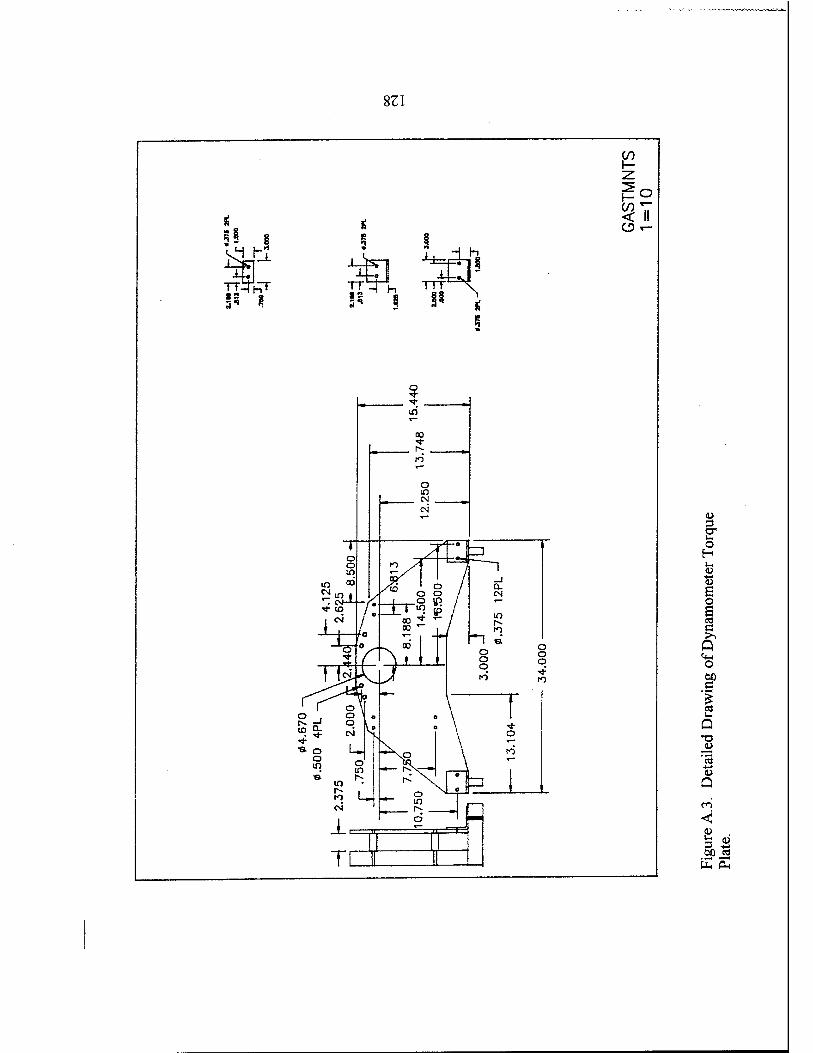
831
er t~ o H
■S3 S o S CO
Q O öD e 1
'3 Q
< U

APPENDIX B. EQUIPMENT LISTING FOR THE AUXILIARY MACHINERY PAD
EQUIPMENT
Heat Exchanger
MANUFACTURER VENDOR
Young Radiator Co. C.H. Bull Co.'
MODEL NUMBER
MWC 26D1Q
Cooling Water
Supply Pump
Fuel Oil Supply
Pump
Cooling Water
Return Pump
Fuel Oil Storage
Tank
Cooling Water
Storage Tank
Bell & Gossett Bell & Gossett2 Series 1531
Centrifugal Pump
Tuthill Corporation Tuthill Corporation3 Model 1 LEV
Teel
Convault
W. W. Grainger4 Model 1P955
Convault5 Model 500 2HF
National BD Roy E. Hanson Serial # 352602
MFG6
NOTE: 1. CH.BullCo. 233 Utah Avenue South San Francisco, CA
94080 (415) 871-8448
2. Bell and Gösset 8200 N. Austin Ave. Morton Grove, IL 60053 (312) 966-3700
3. Tuthill Corporation 12500 South Pulaski Rd Chicago, II 60658 (312) 389-2500
4. W.W Grainger 1334 Dayton Street Salinas, CA 93981 (408) 757-0991
5. Convault 4109 Zeering road Denair, CA 95316 (800) 222-7099
6. Roy E. Hansen MFG Los Angeles, CA
129

130

APPENDIX C. AUXILIARY SUPPORT SYSTEMS EQUIPMENT LISTINGS
C.l. COOLING WATER SYSTEM EQUIPMENT LISTING
Part Number Vendor Nomenclature
1P955 Grainger1 return pump, 2 HP, centrifugal, self priming, internal check valve
5E475 Grainger globe valve, 2" (bronze)
6P969 Grainger gate valve, 2" (bronze)
3P574 Grainger water suction hose (1.5"dia) 25 ft lengths
3P584 Grainger water discharge hose(3" dia) 25 ft lengths
4X515 Grainger pressure gage (0-100 psi)
2A608 Grainger temperature gage (0-25 OF)
2W403 Grainger 1 9/16-2.5" hose clamps
5X446 Grainger 2-5/8-4.5" hose clamps
1A527 Grainger 1/4-5/8" hose clamps
1A528 Grainger 5/16-7/8" hose clamps
5X444 Grainger 0.5-1-1/8" hose clamps
5X443 Grainger 3/8-7/8" hose clamps
1A529 Grainger .5-1.25" hose clamps
3P878 Grainger 1/4" male NPT brass plugs
3P880 Grainger 1/2" male NPT brass plugs
131

3P879 Grainger
3P870 Grainger
3P872 Grainger
2P151 Grainger
5E225 Grainger
5E223 Grainger
5E212 Grainger
5A228 Grainger
10825K5 FILTREX
3/8" male NPT brass plugs
3/8"Xl/4"NPT female NPT brass bushings
1/4" male NPTX 1/4" compression brassbushings
1/4" 45 deg brass flare nuts
permatex RTV silicone gasket sealer
red RTV silicone gasket sealer
loctite, thread locker 222
loctite thread locker 242
50 micron water filter CPL 130-020MT
C.2. FUEL OIL SERVICE SYSTEM
Part Number
PR-7 series
SS-RL4M8F8
SS-CHF12-1
B-45F8-42DC
PB-8
B-PB8-PM8
5E455
2840009399395
Vendor
GO INC3
Sunnyvale Valve4
(Swagelock)
Sunnyvale Valve
Sunnyvale Valve
Sunnyvale Valve
Sunnyvale Valve
Grainger
Federal Stock
Nomenclature
pressure reducing regulator (55/12 psi)
relief valve 1/2" inlet 1/2" discharge adjustable
check valve 3/4" NPT female 316 stainless steel, 1 psi cracking pressure
solenoid valve, 24 volt, 1/2" NPT
fuel hose (75 ft
1/2" push on hose barb male NPT
gate valve threaded 1/2
nozzle assembly, fuel spray
132

2915010402607 Federal Stock filter element (fuel)
P1147G FRAM filter element
P1146G FRAM filter element
C.3. ELECTRICAL SYSTEM EQUIPMENT LISTING
Part Number Vendor Nomenclature
6Z764 Grainger battery charger 20/2 amp
4P052 Interstate Battery5 4 deep cycle marine batteries
E30EA Bell Electrical6 two button momentary switch with 120(Cutler-Hammer) VAC light
E30KE130 Bell Electrical black start button
E30KE231 Bell Electrical red stop button
E30KJ11 Bell Electrical motor run lens
E30DG Bell Electrical push-button with off release bar
10250TN15 Bell Electrical NEMA1 enclosure, 6 hole, grey
DH3610GK Bell Electrical switch, NEMA1 enclosure, fusible, heavy duty,3 pole, 480 VAC
MCC 2100 Bell Electrical motor control cabinet
2925011434229 Federal Stock starter generator
5945007552301 Federal Stock starter/generator relay
6110001388687 Federal Stock voltage regulator
8040-002 Turbomotive7 Nl & N2 Tachometers
CDPEDA Turbomotive engine dress adapter
133

C.4. AIR SYSTEM EQUIPMENT LISTING
Part Number Vendor Nomenclature
3C243 Grainger ceiling intake shutters
2C904 Grainger shutter motors
8.13/16.003N5052 Texas Almet Inc.8 aluminum honeycomb sheet
GT12/200 Farr Sales & Svce.9 Riga Flo air filter (24X24X12)
TYPE 8 Farr Sales & Svce. holding frame (24x24)
C-80 Farr Sales & Svce. fasteners
instrumented compressor bellmouth
20-mesh screen (304 stainless steel)
18-mesh screen (304 stainless steel)
structural steel C-channel C-4X6.25 (20')
perforated alum sheet (.5" dia holes)
perforated alum sheet (1.0" dia holes)
alum sheet (. 125X36X144")
steel box beam (2x2")
duct, exhaust rh
duct, exhaust lh
8045-033 Turbomotive9
9226T5 Carr Supply10
9226T47 Carr Supply
N/A Valley Fab."
N/A Valley Fab.
N/A Valley Fab.
N/A Valley Fab.
N/A Valley Fab.
2840001316405 Federal Stock
2840002229249 FederalStock
134

C.5. OIL SYSTEM AND SPECIAL EQUIPMENT LISTING
Part Number Vendor Nomenclature
5T903 Grainger dry chemical fire extinguishers
9150001806266 Federal Stock lubricating oil MIL-L-23699
2840001988610 Federal Stock tank, lubricating oil
2935001216554 Federal Stock cooler, lubricating
Special Fab. Turbomotive shaft
Special Fab. Turbomotive adapter (shaft)
NOTE: 1 W.W. Grainger 1334 Dayton street Salinas, CA 93901 (408) 757-0991
2. FILTREX Corp. 1945 Alpine Way Hayward, CA 94545 (510) 783-3700
3. GO Inc. 305 S. Acacia St San Dimas, CA 91773 (909) 599-6245
4. Sunnyvale Valve 929 Weddell Court Sunnyvale, CA 94089 (408)734-3145
135
5. Interstate Battery 213 N. Main Salinas, CA 93901 (408)758-6411
6. Bell Electrical 536 Brunken Ave. Salinas, CA 93901 (408)758-6110
7. Turbomotive Inc. 285 Welton St Hamden,CT 06517 (203) 789-0243
8. Texas Almet Inc. 2800 E.Randall Mill Rd Arlington, TX 76011 (817)649-7056
9. Fair Sales and Service 2201 Park Place El Segundo, CA 90245 (310)536-6787
10. Carr Supply Co. PO Box 54960 Los Angeles, CA 90054 (213)692-5911
11. Valley Fabricators 63 7Abbott Street Salinas, CA 93912 (408)757-5151
136

APPENDIX D. MATLAB COMPUTER SIMULATION PROGRAM CODES AND HEAT EXCHANGER SPECIFICATION SHEET
D.I. MATLAB CODE FOR THERMODYNAMIC SIMULATION OF THE COOLING WATER SYSTEM.
clear
ttable=60:10:200;
hforl5=[28.10 38.09 48.08 58.06 68.04 78.02 88.00 97.99 107.98 117 98 127 98 138 00 148.02 158.05 168.09];
hfor36=[28.16 38.15 48.13 58.11 68.09 78.07 88.05 98.04 108.03 118 03 128 03 138 05 148.07 158.10 168.14];
hfor70=[28.26 38.25 48.23 58.20 68.18 78.16 88.14 98.13 108.12 118 11 128 12 138 13 148.15 158.18 168.22];
o
% hl,h2,h3,h4,h5 = enthalpy values (Btu/lbm) % pl,p2,p3,p4,p5 = pressure values (psi) % tl,t2,t3,t4,t5 = temperature values (F) % vgps = volumetric flow rate (gps) % mdot = mass flow rate (lbm/sec) % tamb = ambient air temp, (deg F) % hp = engine power (hp) % q!2 = heat added by dyno water brake (Btu/sec) % cf = heat exchanger capacity factor (Btu/sec F) % q34 = heat extracted by heat exchanger (Btu/sec) % delt = time interval (sec) % htank = mixing cup enthalpy for water supply tank (Btu/lbm) % frc = mass fraction of tank volume entering % vtank = volume of tank (gallons) % delv = change in tank volume per unit time % hpre4 = enthalpy from previous calculation (Btu/lbm) % ttank = bulk temp, of tank (F) % g = gravitational accel. (ft/secA2) %beta = coefficient of thermal expansion (1/R) % d = diameter tank (ft)
137

%nu %RaD %Pr %NuD %h % q45 %kair % sarea
kinematic viscosity (ftA2/sec) Rayleigh number
Prandtl number Nusselt number free convection ht.coef. (Btu/sec ftA2 F) heat removed from tank by free convection (Btu/sec) thermal conductivity for air (Btu/sec ft F) external surface area of the tank (ftA2)
% define constant variables pl = 70; p2 = 15; p3 = 36; p4 = 36; P5 = 15; cf = 0.825; vtank = 1040 g = 32.17; d = 4; nu = 1.6e-4; Pr = •7; kair = 4.54e-6 sarea = pi*d*12
% define variables which may change due to operational needs and ambient conditions.
tamb = 60; time = 200; delt = 60; hp = 250; hpre4 = Interp 1 (ttable,hfor 15 ,tamb) vgps = hp/10/60; mdot = 62.38/7.48 l*vgps; hi zeros(l,time);. h2 zeros(l,time); h3 zeros(l,time); h4 zeros(l,time); h5 zeros(l,time); htank = zeros(l,time); tl zeros(l,time); t2 zeros(l,time);
138
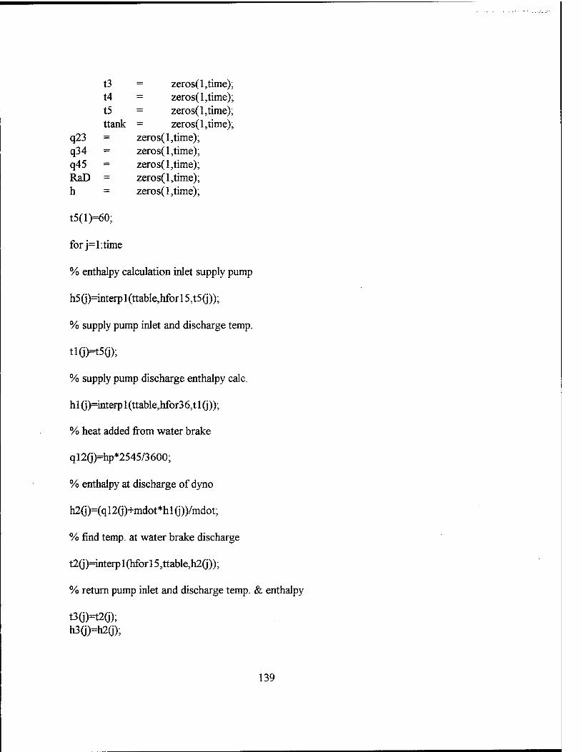
t3 = zeros(l,time); t4 = zeros(l,time); t5 = zeros(l,time); ttank = zeros(l,time);
q23 = zeros(l,time); q34 = zeros(l,time); q45 = zeros(l,time); RaD = zeros(l,time); h = zeros(l,time);
t5(l)=60;
forj=l:time
% enthalpy calculation inlet supply pump
h5(j)=interpl (ttable,hfor 15,t5(j));
% supply pump inlet and discharge temp.
ti(jH5(j);
% supply pump discharge enthalpy calc.
hi (j)=interp 1 (ttable,hfor3 6,t 1 (j));
% heat added from water brake
ql2(j)=hp*2545/3600;
% enthalpy at discharge of dyno
h2(j)=(q 12(j)+mdot*h 1 (j))/mdot;
% find temp, at water brake discharge
t2(j)=interp 1 (hfor 15,ttable,h2(j));
% return pump inlet and discharge temp. & enthalpy
t3(j)=t2ö); h3(j)=h2G);
139

% heat extracted in the ht. ex.
q340>cf*(t3(j)-tamb);
% find enthalpy at discharge of ht. ex.
h4(j)=(mdot*h3(j)-q34(j))/mdot;
% find temp, at discharge of ht. ex.
t4(j)=interp 1 (hfor36,ttable,h4(j));
% find bulk enthalpy of tank
frc=vgps*delt/vtank;
htank(j)=frc*h4(j)+( 1 -frc)*hpre4;
hpre4=htank(j);
% find bulk temp, of tank
ttank(j)=interp 1 (hfor 15,ttable,htank(j));
% Rayleigh number for tank (free convection)
beta=l/(460+(tamb+ttank(j))/2); RaDö)=g*beta*(ttank(j)-tamb)*dA3*Pr/nuA2;
% ht. coefficient for tank
h(j)=kair/d*(0.6+0.387*RaD(j)A(l/6)/(l+(0.559/Pr)A(9/16))A(8/27))A2;
q45(j)=h(j)*sarea*(ttank(j)-tamb);
% bulk enthalpy of tank
h5ö)=(mdot*htank(j)-q45(j))/mdot;
% bulk temp, of tank
t5G+1 )=interp 1 (hforl 5,ttable,h5(j));
140
end
timel=l:time;
t5=t5(:,[2:time+l]);
grid;
plot(time 1 ,t 1 ,'r',time 1 ,t2,'g',time 1 ,t4,'m');grid
xlabel(TIME (MIN)0;ylabel('TEMPERATURE (F)');
axis ([0 200 60 200]);
title(WATER TEMPERATURE VS TIME @ 250 HP (STORAGE TANK CAP. 2080GAL)')
gtext(*DYNO INLET TEMP')
gtext(T>YNO DISCH./HXGER INLET TEMP') gtext('HXGER DISCH TEMP') %print -depsc2 fig6_3 %plot(timel ,hp 1 ,'r*,timel ,q34,'g',timel ,q45,'m') %titleCHEAT RATE VS TIME @ 250 HP ( 2.0*CF )'); %axis ([0 300 0 300]) %xlabel('TIME (MINy^ylabelCHEAT RATE (HP)'); %gtext(TREE CONVECTION HEAT RATE') %gtextCHEAT EXCHANGER REJECTION RATE*) %gtext(*ENGINE HEAT RATE')
141

zn
-§: ;:S m if
s §-
"*■-!
i 2 :"g S'
•N't' ̂ *
I
-IS
I
S2- ii
§1
«Jh ^p
s
^C a
RR
8
ss:S
r fe 8
13
15
£
«I si
8
m
8
8
«<2
g
*
fc«
$#S8
"■§;
RgS RS38
C*"
8«
ß
RSS
VL
m 5n
6
8
i?»
8
ss
§53
§1
3
8
ISS
2S5S}
S8 ss» g<5«l
a
SÖ8
S
SR« 4T! «I
Ö
sss
s
»51
8
O <+-< PH
o <i> cfl
JÜ 0) <JX 00 c o Ä
■*-> o o £ o * <u 0>
ffi
n O
s 3 C CO
CN P
S
r—•
a o~ ^ ?n Q ^ £ NO ^

APPENDIX E. STANDARD OPERATIONAL PROCEEDURES FOR ALIGNMENT AND OPERATION OF THE GAS TURBINE AND
DYNAMOMETER TEST SYSTEM
143

MASTER LIGHTOFF PROCEDURE (MLOP)
SYSTEM VERIFICATION. ALIGNMENT PROCEDURES. AND OPERATING PROCEDURES
PROCEDURE
PLACING THE GAS TURBINE TEST CELL INTO OPERATION
1. Conduct visual inspection of gas turbine test cell and verify the following:
a. Ensure all drip pans, piping trenches, and the deck are free of oil, fuel, or any flammable liquids.
b. Ensure all flammable liquids are stored properly in the flammable liquids locker.
c. Ensure all small parts, equipment, tools, or objects, which may become airborne debris, are properly stored.
d. Verify that the gas turbine test cell and work area fire extinguishers are fully charged.
e. Inspect all piping runs and accessories for loose connections, damage, or leaks.
f. Ensure all valve handwheels are installed and valve labels are in place.
g. Inspect the air intake louvers for blockage. Also verify the fire dampers behind the FOD screen are open.
h. Check the engine battery voltage. Place the batteries on charge if voltage is below 22 VOLTS.
i. Check fuel level in fuel oil storage tank. Ensure enough fuel is present to support gas turbine operations.
j. Verify that the water storage tank is full.
If gas turbine test cell and diesel test cell have been idle for more than 30 days, the water system and fuel system must be recirculated prior to placing the systems into operation. Proceed to the fuel oil service recirculation procedure (FOSRP) and the cooling water system recirculation procedure (CWSRP).
If the ambient air temperature is less 50 °F, the fuel system must be recirculated in order to ensure no paraffin separation is present. Proceed to the fuel oil service recirculation procedure (FOSRP).
144

4. Ensure the cooling water system filter is clean and free of excessive particulate.
WATER SYSTEM ALIGNMENT
1. Ensure the following valves are in the fully open position:
a. Water storage tank suction valve CW-1
b. Water supply pump suction valve CW-2GT
c. Water supply pump discharge valve CW-4GT
d. Dynamometer sump tank supply valve CW-6GT
e. Return pump discharge valve CW-9GT
f. Heat exchanger inlet valve CW-10
g. Heat exchanger discharge valve CW-12
2. Ensure the following valves are in the fully closed position:
a. Diesel supply pump suction valve CW-2D
b. Gas turbine to diesel cross connect valve CW-5
c. Dynamometer bypass valve CW-7GT
d. Diesel return pump discharge valve CW-9D
e. Heat exchanger bypass valve CW-11
3. Place the local heat exchanger breaker [ ] in the AUTO position.
4. Place the local cooling water supply pump breaker [ ] in the AUTO position.
5. Place the local cooling water return pump breaker [ ] in
145
the AUTO position.

FUEL OIL SYSTEM ALIGNMENT
1. Ensure the following valves are in the fully open position:
a. Fuel oil supply pump suction valve FOS-2GT
b. Fuel oil supply pump discharge valve FOS-5GT
c. Fuel oil supply cell isolation valve FOS-6GT
d. Fuel oil return valve FOS-12GT
2. Place the local fuel oil supply pump breaker [ ] in the AUTO position.
3. Ensure the fuel oil service flow regulator is adjusted between 6-10 PSIG.
4. Ensure the following valves are in the fully closed position:
a. Diesel fuel oil supply pump suction valve FOS-2D
b. Fuel oil supply cross-connect valve FOS-3
c. Fuel oil recirculation valve FOS-9GT
d. Diesel fuel oil return valve FOS-10D
5. Ensure the dynamometer to engine fuel line quick disconnect is properly connected.
OIL SYSTEM VERIFICATION
WARNING: Synthetic lube oilMIL-L 23699 can cause dermatitis or paralysis. If lube oil contacts skin, immediately flush with water. If clothing becomes saturated remove promptly.
1. Verify the lubrication oil level in the oil storage tank is above the fill mark (6 gallon level).
2. Ensure the oil pressure sensing line is connected to the dynamometer instrumentation rack connection.
146

3. Ensure the oil supply and discharge lines are properly connected to accessories gearbox.
4. Ensure the shaft is free to turn by rotating manually.
5. Turn on the lubrication oil cooler cooling fan.
ENGINE CHECKS AND ADJUSTMENTS
1. Check gas generator (Nl) fuel control lever travel. Ensure full travel form 0-90° settings. For full travel, lever must contact lever stop. Also ensure that the 0° position actuates the spring fuel cut-off on the governor actuator.
2. Check the power turbine governor (N2) for full travel from control console throttle lever.
3. Ensure all protective covers and plugs are removed from all vents and drains.
4. Ensure the battery charger is disconnected from the storage batteries.
5. Ensure the air flow turbines are connected to the dynamometer instrumentation rack.
6. Obtain the latest barometric reading.
7. Verify that the IGNITION switch and FUEL PUMP switch are in the OFF position.
8. Place the LOAD CONTROL switch in the MANUAL position.
9. Place the THROTTLE CONTROL switch in the MANUAL position.
10. Press the POWER ON push-button to energize the dyno control console.
11. Set the shaft OVERSPEED knob at 6,300 RPM.
147
12. Set the TEMPERATURE METER knob to the LOAD position. Adjust the manual LOAD CONTROL knob to read 8 VOLTS on the TEMPERATURE/VOLT meter scale.
13. Set the TORQUE/POWER display knob to the LOW scale.
14. Set the SPEED display knob to the LOW speed scale.
15. Adjust the UPPER TEST SPEED knob to 6,000 RPM.
16. Set the fuel specific gravity knob to the proper setting.
17. Turn the FUEL mode knob to the A configuration.
18. Set the AIR-FUEL meter knob in the AIR/2 configuration.
19. Set the water vapor pressure knob to the correct setting.
20. Turn the shutter motor breaker [ ] to the ON position. Ensure that the intake shutters move to the open position.
21. Ensure both test cell entrance doors are closed and latched.
ENGINE STARTING PROCEDURE
1. Before the first engine start, motor the engine and check for oil pressure and leaks. Energize starter to 10,000 RPM and release.
2. Turn the remote cooling water supply pump breaker [ ] to the ON position.
3. Turn the remote heat exchanger breaker [ ] to the ON position.
4. Turn the remote fuel oil pump breaker [ ] to the ON position.
5. Place the Nl gas generator lever in the 0° (fuel cut-off) position using the manual throttle lever on the control console.
148
6. Place the power turbine governor N2 lever to 90°.
7. Turn the FUEL PUMP switch to the ON position.
8. Turn the remote cooling water return pump breaker [ ] to the ON position.
9. Turn the IGNITION switch ON and press the STARTER push-button simultaneously.
CAUTION
Do not operate ignition for more than three minutes continually in any 30 minute period. The ignition may be operated two minutes on, three minutes off, and two minutes on in any 30 minute period.
10. Verify positive lubrication oil pressure.
11. Monitor all console warning lights.
12. Advance the gas generator throttle lever (Nl) to the 30° (idle position) as Nl passes 8,000 RPM (16%).
13. Verify an increase in power turbine speed (N2) by the time Nl speed reaches 20,000 RPM (40%).
14. Monitor turbine outlet temperature. Ensure that TOT does not exceed 1,380 °F for more than ten seconds or 1,700°F for more than one second.
15. Ensure gas generator speed reaches a steady state idle speed of 30,000 RPM (60%).
16. Release the STARTER push-button and turn the IGNITION switch OFF when Nl is at idle (60%).
17. Adjust the manual LOAD CONTROL knob and gas generator control lever as required for engine testing.
149
NOTE: Abort start by returning the gas generator throttle lever to the 0° position and securing dynamometer fuel pump if any of the following abnormal conditions occur during system start up:
1. Time from starter ON to idle speed exceeds one minute.
2. Engine oil pressure does not start to increase before Nl speed reaches 10,000 RPM (20%).
3. No indication of power turbine speed N2 before gas generator speed Nl reaches 20,000 RPM (40%).
4. Turbine outlet temperature exceeds 1,380 °F for more than 10 seconds or 1,700 °F for more than one second.
5. A WATER SUPPLY warning light illuminates which indicates a supply water pressure of less than 15 PSIG is available to the power absorber.
6. A DYNO PRIME warning light illuminates indicating that the power absorber must be reprimed.
7. A FUEL PRESSURE warning light illuminates indicating less than 4 PSIG fuel pressure.
8. The OIL PRESSURE warning light illuminates after Nl speed reaches 10,000 RPM (20%).
9. The OVERSPEED warning light illuminates.
10. An unusual sound or vibration occurs.
ILA fuel or lubrication oil leak is observed.
150

151

191
5*1
1»
1
W
I

FUEL OIL SYSTEM RECIRCULATION PROCEDURE (FOSRP)
PROCEDURE
SYSTEM ALIGNMENT FOR RECIRCULATION
1. Conduct visual inspection of gas turbine test cell and verify the following:
a. Ensure all drip pans, piping trenches, and the deck are free of oil, fuel, or any flammable liquids.
b. Ensure all flammable liquids are stored properly in the flammable liquids locker.
c. Verify that the gas turbine test cell and work area fire extinguishers are fully charged.
d. Inspect all piping runs and accessories for loose connections, damage, or leaks.
e. Ensure all valve handwheels are installed and valve labels are in place.
f. Check fuel level in fuel oil storage tank. Ensure enough fuel is present to support gas turbine operations.
g. Ensure the intake shutters are closed.
h. Ensure that the battery charger is disconnected.
2. Ensure the following valves are in the fully open position:
a. Fuel oil supply pump suction valve FOS-2GT
b. Fuel oil supply pump discharge valve FOS-5GT
c. Fuel oil supply cell isolation valve FOS-6GT
d. Fuel oil recirculation valve FOS-9GT
f. Fuel oil return valve FOS-12GT
3. Ensure the fuel oil service flow regulator is adjusted between 6-10 PSIG.
4. Ensure the following valves are in the fully closed position:
a. Diesel fuel oil supply pump suction valve FOS-2D
153

b. Fuel oil supply cross-connect valve FOS-3
c. Diesel fuel oil return valve FOS-10D
5. Place the local fuel oil supply pump breaker [ ] in the AUTO position.
6. Turn the remote fuel oil pump breaker [ ] to the ON position.
7. Monitor system for possible leaks.
NOTE: The system will recirculate and filter fuel at a rate of 60 gallons per hour. The total storage tank capacity is 500 gallons.
154
COOLING WATER SYSTEM RECIRCULATION PROCEDURE (CWSRP)
PROCEDURE
SYSTEM ALIGNMENT FOR RECIRCULATION
1. Conduct visual inspection of gas turbine test cell and verify the following:
a. Inspect all piping runs and accessories for loose connections, damage, or leaks.
b. Ensure all valve hand wheels are installed and valve labels are in place.
c. Verify that the water storage tank is full.
d. Ensure the cooling water system filter is clean and free of excessive particulate.
2. Ensure the following valves are in the fully open position:
a. Water storage tank suction valve CW-1
b. Water supply pump suction valve CW-2GT
c. Water supply pump discharge valve CW-4GT
d. Dynamometer bypass valve CW-7GT
e. Heat exchanger bypass valve CW-11
3. Ensure the following valves are in the fully closed position:
a. Diesel supply pump suction valve CW-2D
b. Gas turbine to diesel cross connect valve CW-5
c. Dynamometer sump tank supply valve CW-6GT
d. Diesel return pump discharge valve CW-9D
e. Return pump discharge valve CW-9GT
f. Heat exchanger inlet valve CW-10
g. Heat exchanger discharge valve CW-12
4. Place the local cooling water supply pump breaker [ ] in the AUTO position.
155

Monitor system and check for leaks.
NOTE: The water will recirculate at 50 gallons per minute. A full tank will recirculate once every 20 minutes. It is recommended that the system be placed into recirculation mode for a minimum of 40 minutes if the system has been idle more than 30 days.
156
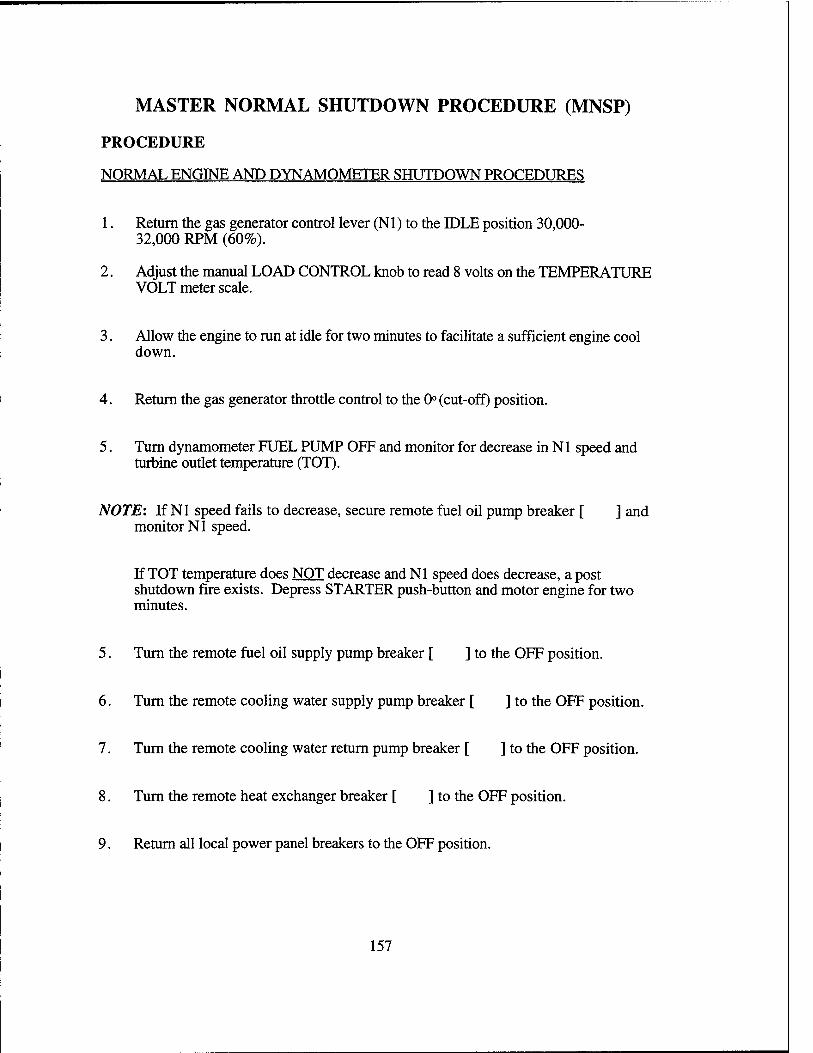
MASTER NORMAL SHUTDOWN PROCEDURE (MNSP)
PROCEDURE
NORMAL ENGINE AND DYNAMOMETER SHUTDOWN PROCEDURES
1. Return the gas generator control lever (Nl) to the IDLE position 30,000- 32,000 RPM (60%).
2. Adjust the manual LOAD CONTROL knob to read 8 volts on the TEMPERATURE VOLT meter scale.
3. Allow the engine to run at idle for two minutes to facilitate a sufficient engine cool down.
4. Return the gas generator throttle control to the 0° (cut-off) position.
5. Turn dynamometer FUEL PUMP OFF and monitor for decrease in N1 speed and turbine outlet temperature (TOT).
NOTE: If Nl speed fails to decrease, secure remote fuel oil pump breaker [ ] and monitor Nl speed.
If TOT temperature does NOT decrease and Nl speed does decrease, a post shutdown fire exists. Depress STARTER push-button and motor engine for two minutes.
5. Turn the remote fuel oil supply pump breaker [ ] to the OFF position.
6. Turn the remote cooling water supply pump breaker [ ] to the OFF position.
7. Turn the remote cooling water return pump breaker [ ] to the OFF position.
8. Turn the remote heat exchanger breaker [ ] to the OFF position.
9. Return all local power panel breakers to the OFF position.
157
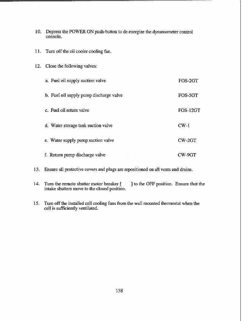
10. Depress the POWER ON push-button to de energize the dynamometer control console.
11. Turn off the oil cooler cooling fan.
12. Close the following valves:
a. Fuel oil supply suction valve FOS-2GT
b. Fuel oil supply pump discharge valve FOS-5GT
c. Fuel oil return valve FOS-12GT
d. Water storage tank suction valve CW-1
e. Water supply pump suction valve CW-2GT
f. Return pump discharge valve CW-9GT
13. Ensure all protective covers and plugs are repositioned on all vents and drains.
14. Turn the remote shutter motor breaker [ ] to the OFF position. Ensure that the intake shutters move to the closed position.
15. Turn off the installed cell cooling fans from the wall mounted thermostat when the cell is sufficiently ventilated.
158

EMERGENCY SHUTDOWN PROCEDURE (ESP)
IMMEDIATE AND CONTROLLING ACTIONS FOR EMERGENCY SHUTDOWN OF THE GAS TURBINE TEST CELL.
NOTE: Emergency shutdown of the T63-A-700 gas turbine engine and dynamometer is directed for any one or combinations of the following casualties:
a. A WATER SUPPLY warning light illuminates which indicates a supply water pressure of less than 15 PSIG is available to the power absorber.
b. A DYNO PRIME warning light illuminates indicating that the power absorber has lost prime.
c. A FUEL PRESSURE warning light illuminates indicating that there is less than 4 PSIG fuel pressure.
d. A fuel oil leak occurs.
e. A WATER TEMP, warning light illuminates indicating a power absorber cooling water discharge temperature of over 210 °F. A normal shutdown should be initiated IAW EOP MNSP if a cooling water discharge of 160 °F or above is observed.
f. An oil pressure of less than 90 PSIG is observed, an automatic shutdown should occur if an oil pressure less than 50 PSIG occurs.
g. An oil leak occurs.
h. An unusual metallic or vibrational sound occurs.
i. The overspeed warning light is illuminated.
j. A fire of any type or severity is observed.
k. A gas generator overspeed of 53,164 RPM (104%) is observed.
159
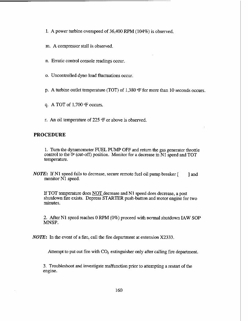
1. A power turbine overspeed of 36,400 RPM (104%) is observed,
m. A compressor stall is observed,
n. Erratic control console readings occur,
o. Uncontrolled dyno load fluctuations occur.
p. A turbine outlet temperature (TOT) of 1,380 °F for more than 10 seconds occurs,
q. A TOT of 1,700 °F occurs.
r. An oil temperature of 225 °F or above is observed.
PROCEDURE
1. Turn the dynamometer FUEL PUMP OFF and return the gas generator throttle control to the 0° (cut-off) position. Monitor for a decrease in Nl speed and TOT temperature.
NOTE: If Nl speed fails to decrease, secure remote fuel oil pump breaker [ ] and monitor Nl speed.
If TOT temperature does NOT decrease and Nl speed does decrease, a post shutdown fire exists. Depress STARTER push-button and motor engine for two minutes.
2. After Nl speed reaches 0 RPM (0%) proceed with normal shutdown IAW SOP MNSP.
NOTE: In the event of a fire, call the fire department at extension X2333.
Attempt to put out fire with C02 extinguisher only after calling fire department.
3. Troubleshoot and investigate malfunction prior to attempting a restart of the engine.
160

LIST OF REFERENCES
1. Allison Gas Turbines, Model-CIS Installation Design Manual, 1976
2. Department of the United States Army, Aviation Unit andAviaition Intermediate Maintenance Manual, TM 55-2840-231-23,1982
3. Point of Contact Thomas F. Piercy, Chief Test Engineer, Allison Engine CO - Mail Code 515 Indianapolis, IN 46206, PH: (317) 230-5406, May 1995
4. Point of Contact Rod Gwillam, Executive V.P., Turbomotive Inc., 285 Welton Street, Hamden CT 06517, PH (203) 789-0243, June 1995
5. Superflow Corporation, SF-901 Instruction Manual, 1993
6. Point of Contact Mike Girdley, Allison 250 Customer Service Representative, Allison Engine CO - Mail Code P40A Indianapolis, IN 46206 PH: (317)230- 2718
7. Point of Contact Tom Paullins, Superflow Corp. Customer Service Representative 3512 N.Tejon, Colorado Springs, CO 80907 PH: (719)471-1746
8. Point of Contact Leslie Jordan, Customer Service Representative California- AmericanWater Company of Monterey CA, PH (408) 375-8845 Jan 1995
9. Streeter, V.L.and Wylie,E. B. "Fluid Mechanics " 8th edition, McGraw Hill, 1985
10. Department of the United States Army, Aviation Maintenance Repair Parts and Special Tools List and Technical Manual, TM 55-1520-228-23P, 1982
11. Point of Contact Rey Schmidt, Engineered Products Divisiion, C.H. Bull CO., 233 Utah Avenue, South San Francisco CA, 94080 PH: (415) 871-8448, Quotation 5228-S May 1995
12. Department of the United States Army, Operator's Manual Army Model OH-58A/C Helicopter, TM 55-1520-228-10, 1982
161

162
INITIAL DISTRIBUTION LIST
No. Copies
1. Defense Technical Information Center 2 Cameron Station Alexandria, VA 22304-6145
2. Library, Code 013 2 Naval Postgraduate School Monterey, California 93943-5101
3. Department Chairman, Code ME 1 Department of Mechanical Engineering Naval Postgraduate School Monterey, California 93943-5000
4. Professor Knox T. Millsaps, Jr., Code ME/MI 4 Department of Mechanical Engineering Naval Postgraduate School Monterey, California 93943-5000
5. LT Brian P. Eckerle,USN 2 401 N. 21st Avenue Hattiesburg, MS 39401
6. Curricular Officer, Code 34 1 Department of Mechanical Engineering Naval Postgraduate School Monterey, California 93943-5100
7. Naval Sea Systems Command 1 Director, Engines Division (SEA S6X3) Washington D.C. 20362
8. LT David Haas, USN 1 Department of Mechanical Engineering Naval Postgraduate School Monterey, California 93943-5100
9. Thomas H. McCord 1 Department of Mechanical Engineering Naval Postgraduate School Monterey, California 93943-5000
163

10. James Schofield Department of Mechanical Engineering Naval Postgraduate School Monterey, California 93943-5000
11. Frank Frenzen Department of Mechanical Engineering Naval Postgraduate School Monterey, California 93943-5000
12. Maj or John Harvell / Jerry Stermer USAFA/DFAN USAF Academy, CO 80840
13. Mr. W. E. Barksdale 401 N. 21st Avenue Hattiesburg, MS 39401
14. Mr. Michael Girdley Allison Engine Company Mail Code P40A Indianapolis, IN 46206
15. Mr. Rod Gwillam Turbomotive, Inc. Wellton Street Hamden,CT 06517
164