design and experience with a 30,000 hp magnetic …
TRANSCRIPT

Horst Kümmlee is Head of the R&DDepartment for large rotating electricalmachines in Siemens Dynamowerk, inBerlin, Germany. He is responsible forbasic mechanical and electrical design,rotordynamics, simulation of electromech-anical systems, measurement proceduresand systems, and standardization. He hasbeen at Dynamowerk since 1985 asResearch Engineer, Head of the specialmachines order processing and design
department, and in his current position.Dr. Kümmlee graduated from the Technical University Berlin
with a Dipl.Ing. degree (Mechanical Engineering, 1980), andreceived the degree of Dr.-Ing. for work on hyperelastic couplingelements and dampers (1985).
Gerrit M. Lenderink is Manager ofCompressor & Pump Engineering forDemag Delaval Turbomachinery B.V., inHengelo, The Netherlands. He joinedDemag Delaval in 1979 and has more than20 years of diversified experience in thefields of design, application engineering,and product development of centrifugalcompressors. He has been heavily involvedin the development of dry-dry compressorsfeaturing dry gas seals and magnetic
bearings.Mr. Lenderink has a B.Sc. degree (Mechanical Engineering,
1979) from the Enschede Institute of Technology.
Wim H. de Groot is the Senior RotatingEquipment Engineer in the GLTproject team of Nederlandse AardolieMaatschappij B.V. (NAM), in Hoogezand,The Netherlands, where he serves as anadvisor. Mr. de Groot was instrumental inthe development of the functional speci-fication and selection of the consortiummembers. He joined the NAM in 1971 andworked on several gas and oil fielddevelopment projects.
Mr. de Groot has B.Sc. degrees (Mechanical Engineering, 1969;Contracts Engineering, 1971) from the Groningen Institute ofTechnology.
ABSTRACT
In the Northern Netherlands, after more than 30 years ofproduction, the pressure of the gigantic Groningen onshore gasfield is gradually decreasing, requiring up to 500 MW compressionover the next 30 years to fulfil capacity obligations. Within aunique technical and contractual concept, up to 29 electric motordriven centrifugal compressors with 120 bar (1741 psi) dischargepressure will be installed to maintain the necessary input pressurefor the Dutch pipeline network. Based on a thorough total cost ofownership evaluation, and considering the extended projectduration and its special requirements, a future-orientedcompression string was devised and installed in 1998, serving asthe prototype for the remaining installations. Performance, design,and construction features of this oil-free turbocompressor stringare described, highlighting the rotordynamic aspects of thesupercritical rotating string with its extremely wide continuousoperating speed range. The design aspects of the magnetic bearings
65
DESIGN AND EXPERIENCE WITH A 30,000 HP MAGNETIC BEARING SUPPORTEDMOTOR DRIVEN TURBOCOMPRESSOR FOR A SPEED RANGE OF 600 TO 6300 RPM
byHorst Kümmlee
Manager, Large Special Machines
Siemens AG
Berlin, Germany
Gerrit M. LenderinkManager, Compressor & Pump Engineering
Demag Delaval Turbomachinery B.V.
Hengelo, The Netherlands
Wim H. de GrootSenior Rotating Equipment Engineer
Nederlandse Aardolie Maatschappij B.V.
Hoogezand, The Netherlands
andRichard R. ShultzOperations Manager
Federal Mogul Magnetic Bearings
Mystic, Connecticut

are emphasized. Test results and initial field experience areaddressed. Lessons learned and a recommendation for the APIStandards Committee conclude the paper.
INTRODUCTION
In 1959, Nederlandse Aardolie Maatschappij (NAM, hereinafterreferred to as “the joint venture”), a 50/50 exploration andproduction joint venture of Shell and Esso, discovered largeamounts of natural gas in the province of Groningen, in the northernpart of The Netherlands. It turned out to be one of the largest gasreservoirs in the world. The production installations in theGroningen system consist of 29 standardized “well clusters,” with atotal of 300 wells. Groningen reserves have now dwindled to lessthan half the initially recoverable 2700 billion Nm3, and the pressurein the field has declined from an original 345 bar (5004 psi) to about145 bar (2103 psi) last year; free-flow capacity is thus rapidlydecreasing. To maintain Groningen’s vital function as a balancingproducer, something had to be done to maintain the NAM’scapability to produce the required annual volume while maintainingsystem capacity. The production capability can only be maintainedby installing compression and by upgrading the clusters to the latesttechnology. In the first phase of an ongoing 15 year project, 11clusters will each be equipped with a 23 MW electric motor drivencentrifugal compressor. Fourteen more are envisioned to beequipped with about 12 MW each. The cluster at Tjuchem, nearSlochteren where the field was discovered, was selected as the firstbenchmark cluster. Its compression string (Figure 1) has now beenin operation for almost two years and it is the subject of this paper.
Figure 1. The Completely “Dry” Compression String at theTjuchem Site of NAM in The Netherlands.
FUNCTIONAL REQUIREMENTS
Following a preselection of nine well known suppliers of largegas compressors, three consortia were invited to participate in adesign competition. This competition was guided by a mere 47page Functional Specification for the compression unit thatchallenged each consortium to come up with their best solution. Itdescribed in detail the expected operational usage of thecompression unit over a 25 year period. It specified the scope ofsupply, the number of starts and stops, the annual load-factor, thedesired operating envelope, the annual change in processconditions, references to API 617 (1995, bullet point paragraphs)
and a Class III PTC-10 (1997) test. The document gave themanufacturers a maximum of freedom, with the objective tooptimize their design to the lowest total cost of ownership (TCoO),often also called life- cycle cost (LCC).
Performance requirements are shown in Figure 2, which is anoverall cluster well performance curve for the existing 11 wells ofthe Tjuchem cluster. It indicates the relationship between theflowing well head pressure and the total well production rates forparticular reservoir pressures. Superimposed is the installation andtransport line indicating the discharge pressure required to ensurethe contractual 65 barg (943 psig) at the custody transfer stationsto Gasunie, the operator of the Dutch gas transmission system. Theiso-power lines indicate the correlation between flow rate andconsumed power assuming a 78 percent compression efficiency.The area enclosed by the 7 MW and 23 MW iso-power linesreflects the expected operating area based on prestudies. This is thearea that, as a minimum, had to be met. The desired operating areais enclosed by the 5 MW and the 30 MW iso-power lines. Theremaining performance envelope between these areas and thedischarge pressure line was expected to be covered by recycle onthe compressor.
Figure 2. Performance Map as Basis for the Design Competitionfor the NAM GLT Project.
The gas delivery contracts of the joint venture require that aquick reaction to changing flow must be accommodated by thefacilities. The pattern of morning and evening peaks must befollowed by the clusters in operation. A startup period of 20minutes for the compressor system in the cluster up to full flowwas specified, plus a minimum of 500 start cycles per year, andthree restarts in one hour. Startup reliability must be at least 99percent and the compressor shall be able to remain pressurizedduring standstill for extended periods (months). Overall productionavailability (for the clusters in operation) shall be at least 96percent and the availability of the compressor-driver unit itself, 98percent during the winter. A no-failure-no-trip methodology mustbe applied in combination with a condition based maintenancephilosophy.
The flat, agricultural landscape for the Groningen area requiresthat the new installations are blended into the existing clusters withminimum silhouette disturbance. There is, furthermore, a definiteneed to stay within the existing boundaries of the clusters. If thisrequirement is not met, additional land for each cluster would beneeded, causing an elaborate acquisition and permit procedurewith the various local authorities.
WHY ELECTRIC MOTORS?
An array of gas turbine options is readily available for the 23MW range. So, why deviate from the traditional gas turbine driver
PROCEEDINGS OF THE 29TH TURBOMACHINERY SYMPOSIUM66

DESIGN AND EXPERIENCE WITH A 30,000 HP MAGNETIC BEARING SUPPORTEDMOTOR DRIVEN TURBOCOMPRESSOR FOR A SPEED RANGE OF 600 TO 6300 RPM 67
option and select an electric motor drive? The joint ventureexecuted a detailed driver option evaluation taking into account:
• Reliability
• Performance
• Economics
• Emissions
• Site specific aspects
Reliability
The electric motor option introduces a dependency on thereliability of the power supply grid. Detailed studies indicated thatthe overall reliability would be at least as good as with the gasturbine option. Instrumental in this was the close proximity of a1700 MW power plant and a high voltage power grid with variousdirect links to the Western European high voltage grid.
As far as the electric motor variable speed drives wereconcerned, the joint venture had very positive experience with evenlarger drives, indicating an overall significantly higher availabilitythan comparable gas turbine drivers.
Performance
The present generation of gas turbines in the 23 MW rangefeatures a peak conversion efficiency on the order of 37 percent.However, by use of the present generation of large commercialcombined cycle power stations to supply an electric drive, anoverall conversion efficiency as high as 52 percent can be achieved.This includes all the transmission losses, i.e., natural gas to powerat the compressor shaft.
The Groningen gas field is used as a peak flow supplier and isalso the backup reservoir for all other gas fields in TheNetherlands, in case they fail to supply. The annual load factor istherefore low (Figure 3). Most of the time (>90 percent), the fieldwill run at loads below 50 percent. At these part load conditions,the conversion efficiency of gas turbines deteriorates to values aslow as 25 percent and lower. However, the power plant feeding theelectric drivers will maintain running on base load, i.e., conversionefficiency remains close to 52 percent. The net result is asignificant conservation of valuable primary resources for theelectric motor option.
Figure 3. The Annual Load Factor of the Groningen Gas Field IsVery Low Due to its Mainly Peaking Service.
Economics
Purchasing decisions on plant equipment have traditionally beenbased on price. From a purely business point of view, procurementdecisions should be based upon the total cost of ownership. TheTCoO model applied to the Groningen project contains, but is not
limited to, the complete investment costs (CAPEX), and theoperational costs (OPEX) over a period of 25 years. The latterinclude costs of staff, energy consumption, emissions, andmaintenance, including overhauls. The electric motor option cameout significantly lower in terms of CAPEX. Instrumental in thiscase was the close proximity of a strong high voltage power grid.
At the time of the prestudies (1995/1996), the market for electricityin The Netherlands was deregulated and the readily available gasturbine option enabled the joint venture to negotiate an attractivecontract with the local power supplier: the joint venture suppliesnatural gas to power stations and electricity is supplied to the jointventure in return. An energy conversion rate is charged to neutralizethe energy component. The joint venture also pays a fee for thetransport costs. With the energy savings included, as mentioned in theprevious section, the cost difference in energy cost between the gasturbine and the electric motor option are virtually eliminated.
Emissions
The requirements on environmental issues in Holland are high.Although in the corresponding permits only the local emissionswere mentioned, the joint venture also took into account in thedriver selection study the related emissions of CO2 and NOx of thepower stations. Applied to the Groningen project, the overallemissions of the electric motor driven option came outsignificantly lower than for the gas turbine option (Figure 4). Thiswas mainly due to the fact that continuous operation on base loadinherently allows minimizing the CO2 and NOx emissions. Onecould argue that a comparison between combined cycle and simplecycle by default would have this conclusion. However, the low loadfactor would not allow the joint venture to effectively apply thecombined cycle principle for the gas turbine option.
Figure 4. Total CO2 and Nox Emissions Are Significantly Lowerwith Electric Drives.
Similar energy costs, at least as good reliability, and significantlower emissions pushed the selection toward the electric motordrive.
Site Specific Aspects
The noise requirements are stringent at these sites since they arelocated near populated areas. Due to their much smaller (cooling)air volumes and velocities, electric motors are inherently quieterthan gas turbines, and keeping their sound pressure levels below 80dB(A) is not a problem. However, in this project, most of the noiseemissions were not coming from the compressor and its driver, butfrom the connecting pipelines, air-coolers (fans and motors), andpumps. Consequently, the turbocompressor-string could beinstalled outdoors on a flat concrete pad without the usualbuilding—thus the required space for the compressor equipment

PROCEEDINGS OF THE 29TH TURBOMACHINERY SYMPOSIUM68
did not require an extension of real estate, which would haverequired an additional permit procedure.
A compressor enclosure would also affect the cluster silhouettenegatively, which is important because the installations are locatedin a flat landscape. Also considering the safety point and explosionrisks, installing the compressor at grade in the open air is preferred.There are no roofs or walls that will hinder access to thecompressor during maintenance, which, if required, is performedon rainy days under temporarily installed tents. And finally, theomission of a building is also a major cost saving.
INTEGRATED DESIGN APPROACH
From the outset of the project, it was clear that the traditionalprocurement process would not yield the desired innovativecompression system solution because new technology and muchcloser than usual client-vendor relationships were needed. Oncethe decision had been made to use magnetic rather than traditionaloil bearings on the compression string, the manufacturers ofcompressor, motor, and magnetic bearings formed an alliance inthe bidding period for the design competition and took anintegrated design approach for the entire rotating string: the StorkGLT project consortium was formed that includes Demag Delaval(compressor), Siemens AG (motor, drive, and power supply),Federal Mogul (magnetic bearings), Yokogawa (I&C), Stork E&C,and a local construction company.
When properly designed, magnetic bearings offer fundamentaladvantages over traditional oil lubricated bearings—but theirunique operating characteristics require more careful considerationat the design stage. Most notably, the rotational frequencydependency of the magnetic bearings, and their different specificload capacities, make their integration into the overall string designa more demanding process than the simple selection from standardranges used for oil bearings.
There have been instances in early applications where magneticbearings have been applied with the primary goal of removing theoil system, but thereafter their location and operation have beenwith the intent of making them look and behave like oil bearings.This approach led to a compromised design that neither capitalizedon the many benefits of magnetic bearings nor fulfilled oil bearingexpectations.
Within the Stork GLT consortium, the magnetic bearings wereviewed as an enabling technology that is capable of deliveringtechnical, operational, financial, and environmental benefits. Assuch, the integration of the magnetic bearings into the compressorand motor was treated as a primary component of the rotordynamicdesign. In particular, the design and location of the bearingcomponents were an iterative process that was performed with theintent of optimizing the full motor/compressor string rotordynamicperformance by the best arrangement of bearings, backup bearings,seals, and motor and compressor internals. A “traditional” layoutwould have resulted in suboptimal performance.
All the specified functional requirements ask for a very flexible,robust compression string with an extremely wide operating range.A closer look reveals that the differential pressure is proportionalto flow squared, i.e., speed range is the key. The 15,000 actualm3/hr (529,740 ft3/hr) rated capacity and 130 barg (1886 psig)maximum working pressure promote the traditional application ofa small size compressor with high shaft speed in combination witha step-up gearbox. But this solution is far from optimum:
• The majority of the cluster performance envelope remainsuncovered and hence recycle is required.
• The large API 614 (1999) lube oil console associated with thegearbox makes it difficult to satisfy the cluster startup requirementsand to install the compressor at essentially grade level.
• Integration of the compression equipment within the existingcluster plot plan is virtually impossible, and the resulting height ofthe installation would be a major blot on the landscape.
• Although well proven, the gearbox and associated componentsintroduce additional complexity to the installation.
The TCoO-model clearly indicated that the gas turbine solutionwould not be satisfactory in this application mainly due to theenergy savings related to omitting recycling in the prevailing partload operating mode. Therefore, the consortium focused onincreasing the operating speed range preferably all the way downto standstill. It was then obvious that a more pragmatic, innovativeapproach was required, and the consortium decided to opt for anelectric direct drive solution in combination with active magneticbearings and dry gas seals (Figure 5).
Figure 5. The Conceptual Arrangement of the Completely “Dry”Compression String Is Unique in the Industry.
Detailed analytical studies confirmed that operation down to zerospeed would be feasible but not necessarily desirable, and controlstability considerations within the drive system prohibited steady-stateoperation below 10 percent speed. The TCoO-model furthermoreconfirmed that one compressor revamp would be optimum.
COMPRESSOR DESIGN
Figure 6 is the initial five-stage configuration of the 55 tonfabricated compressor. The casing is supported by flexible legsthereby ensuring a true centerline support. This is essential giventhe extremely large operating envelope of this unit. The nozzlespoint upward enabling installation at grade. The bolted end headclosure allows the arrangement of the majority of the auxiliaries atthe compressor outer periphery, which enhances accessibility tothe bearing bracket and simplifies maintenance.
Figure 6. The Five-Stage Centrifugal Compressor with MagneticBearings Is Mounted at Grade Level.

DESIGN AND EXPERIENCE WITH A 30,000 HP MAGNETIC BEARING SUPPORTEDMOTOR DRIVEN TURBOCOMPRESSOR FOR A SPEED RANGE OF 600 TO 6300 RPM 69
The inner bundle, which can be withdrawn as one integral pulloutpack with both end heads and bearing brackets, incorporates the fivefully parametric compressor stages, the inlet section, and the dischargevolute. The parametric concept allowed an optimum compromisebetween performance and rotordynamics. The applied abradablelabyrinth geometry not only introduces some resilience during anonlevitated rundown, but also ensures that the unit can be restartedfollowing a nonlevitated rundown without overhaul. The rotor overalllength is 3845 mm (152 inches), it weighs 2100 kg (4630 lb), and it issupported by two radial magnetic bearings. The large, double acting,axial magnetic bearing is arranged outboard at the nondrive end of theunit. Tandem dry gas seals in combination with segmented carbon ringbarrier seals separate the bearing brackets from the impeller section.
A modular bearing bracket concept was adopted in order tominimize the need to dismantle parts. The magnetic bearings andbackup bearings were installed in radial split brackets bolteddirectly to the casing. Special attention was given to theminimization of tolerance buildup and mechanical runout. Theshaft sleeves for both magnetic bearings and the backup bearingswere hydraulically mounted on the shaft.
MOTOR AND VARIABLE SPEED DRIVE DESIGN
Motor Design
As induction motors with suitable frequency converters are noton the market yet, the only electric motor applicable for thespecified speed and power range is the two-pole brushlesssynchronous motor with a cylindrical, solid steel rotor. A brushlessexciter is solidly coupled to the main rotor. It comprises aninduction generator with a rotating rectifier wheel producing theDC power for the rotating motor field.
The solid steel turbo rotor is supported by three radial magneticbearings, two at the motor section and one at the exciter section.The close to 5 m (5.5 yd) long rotor weighs 9300 kg (20,503 lb)and is essentially built out of two parts: the motor section and theexciter section. A single, high alloyed steel forging is used for themotor section with milled slots for the field winding, and thedamper bars to withstand the centrifugal forces occurring at themaximum rotational speed. Nonmagnetic end caps and retainingwedges form the squirrel-cage damper winding that controlsoscillating torques and harmonic currents in the rotor. Table Ishows the rating data of the motor.
For each active magnetic bearing (AMB) a set of rotor sleeves ishydraulically shrunk onto the shafts (motor and exciter), eachconsisting of a laminated rotor sleeve assembly for the magneticbearing, and a solid sleeve for the auxiliary bearing. This designensures minimum mechanical runout and residual unbalance.
Along with a patented shaft design, the magnetic and backupbearings are arranged in a unique asymmetric way with respect tothe motor/exciter stators. The AMBs on the drive end and exciterend are positioned outboard, while the AMB on the nondrive endis positioned inboard. This is the result of the rotordynamicanalyses searching for the optimum compromise regarding the:
• Rotor behavior with the rotor being controlled by the activemagnetic bearings under operating conditions.
• Rotor behavior with the rotor being supported by the backupbearings under emergency rundown conditions.
• Assembly of the bearings.
The preferred arrangement with respect to easiest assembly andmaintenance of the backup bearings would have been anarrangement with the backup bearings being located outboard.However, this comprises rotordynamics.
The stator of the main motor is a welded housing structure withfour ventilation circuits for symmetrical cooling and a very stifflaminated stator core. The two electrically offset stator windingsare designed for Class F (155°C (311°F)) temperature rise, but theyare only utilized to Class B (130°C (266°F)) in normal operation.
Table 1. Rating Data of High Speed Synchronous Motor.
An air-water cooling system with four heat exchangers and fourradial blowers is integrated into the motor enclosure creating an airflow of 13 m3/sec (459 ft3/sec) removing the maximum 460 kW ofelectrical and windage losses (Figure 7). Electric blowers for theinner cooling circuit were preferred over shaft mounted fans toreduce bearing span and to improve the cooling air distribution atlow speeds. Even with failure of one fan or one cooler, the motorstill can be operated at full power without exceeding the Class Btemperature limit in the winding.
The drive system overall efficiency has been optimized takinginto account the specific requirements of the Groningenapplication—it is still on the order of 70 percent when running at10 percent speed. The motor is electrically optimized to a hightorque-size ratio in order to minimize the bearing span. In addition,the flux versus speed profile is optimized, resulting in close to 98percent motor efficiency over a wide speed range.
Figure 7. A Pressurized Enclosure Ensures Safety and Low Noise,and Symmetrical Cooling over the Entire Speed Range Is Ensuredby Internal Radial Blowers.
Variable Speed Drive
The frequency converter (drive) applied to the Groningen projectis a standardized and modular design that is used in hundreds ofinstallations by several manufacturers: the specific model is of thesimple load-commutated inverter (LCI) type in a parallel 12-pulseconfiguration, using high power thyristors as their solid stateswitching devices. In this type of drive, the motor itself controls thecommutation of the converter thyristors (and thus its outputfrequency), and the motor current (which roughly equals torque sincethe flux in a synchronous motor is kept constant) is electronicallycontrolled by varying the voltage in the DC link circuit.
The construction of the Megawatt size LCI converters ismodular. The heat producing components are water cooled bymeans of a closed loop deionized water circuit. The DC linkreactors are also directly water cooled and integrated into the driveenclosure, simplifying its installation and reducing footprint andcosts at the same time. To accommodate the client’s requirementsfor comprehensive type and performance tests prior to the jobsiteinstallation, all major subsystems were constructed as
Rated power & speed 23 000 kW @ 5400 rpmSpeed control range 600...6300 rpmConstant power speed range 5400...6300 rpmRated voltage / current 2*3600 V / 2*2030AMotor efficiency 98,0 %Total motor weight / dimensions 70 t / 7m*3m*4,5mTotal rotor weight / length 9,3 t / 6,4mBearing span (main+exciter) 3,7m + 1,4mHazardous area classification EExpII T3 (pressurized)

prefabricated modules on skids that were then installed inside thesite erected buildings. Buildings were required for architecturalreasons in this case.
Nonlinear electric loads, such as these frequency converters,produce harmonic currents that cause voltage distortions in thefeeding power system, and they have a poor power factor at partload and speed. These effects are minded by the utility companysince they can substantially disturb other consumers and makepower transmission inefficient. Based upon a comprehensivenetwork analysis, special circuit configurations and customtailored harmonic filters were selected, reducing the distortions toacceptable levels.
Magnetic Bearings
The radial magnetic bearings, of which there are two in thecompressor and three in the motor (Figure 8), are of the heteropolardesign with two orthogonal axes of control per bearing. The radialbearing axes of control are oriented at 45 degrees from thehorizontal. Silicon steel is used for the rotor and stator laminations.The rotor sleeves are located with a taper fit since the sleeves onthe compressor must be removed to perform maintenance on thedry gas seals.
Figure 8. An Active Magnetic Bearing Design with Levitation(Rear) and Static Mechanical Backup (Front) Fully Controls the9300 Kg Motor Rotor.
The axial bearing in the compressor is a double acting three-pole“E2” type design. Its axial collar is made of a conventional solidmaterial and the stators are fully laminated to yield enhanceddamping and control in the axial dimension.
The winding insulation on both the radial and axial magneticbearings is rated to 180°C (356°F). Control of the rotor is basedupon position and velocity feedback sensors, which are collocated,on common sensor modules. Each radial bearing has sensors atboth the inboard and outboard end of the lamination stacks, and thesensor type is magnetic to allow direct shaft sensing. This isimportant to maintain a stable reference to the inertial axis of therotor and thereby avoid the introduction of geometric runout whenthe compressor lamination sleeves are removed for sealaccessibility.
Backup Bearings
The radial and axial backup bearings are of a dry bushing rotordelevitation system (RDS) design. The radial bearings use an
articulated pad design, allowing the pads to align to the landingsleeve and to provide an adjustable compliant mounting. Thestiffness and damping coefficients of the mounts are tuned tocontrol the dynamic loads and vibration amplitudes during alanding event. In the motor, the backup bearings are split for easeof assembly and maintenance.
The condition of the shaft bushings is observable from thecontrol cabinet after a delevitation by adjusting rotor positionduring static levitation to assess clearance degradation. Thisfeature allows a determination of remaining backup bearing life,without machine disassembly, since wear is the only indicatedfailure mechanism of the bushing material. The dry bushing is alsotolerant to any contamination that may build up during theoperating life of the compressor while the backup bearings are notin use.
During emergency situations—which result from the completeloss of the uninterruptible power system (UPS) supplied AMBpower and control electronic system—the spinning rotor will droponto the backup bearings and is braked to standstill by the resultingfriction. To significantly extend the service life of the backupbearings, the variable speed drive system (VSDS) control will—once it receives a fault message from the AMB controlsystem—electrically brake down the rotating string frommaximum speed to zero within five to 10 seconds—with the helpof the compressor load. In reality, AMB amplifier, control system,and power supply failures are an extremely rare event. Due to theseparately backed up power source of the AMB-system, asimultaneous power loss of VSDS and AMB-control is even moreunlikely.
Bearing Control System
The magnetic bearings for both the motor and compressor arecontrolled by a single combined system. The digital controllerutilizes a rugged virtual machine environment (VME) system tocalculate a complex eighteenth order polynomial for each axis ofcontrol to produce the overall bearing transfer function. The poweramplifiers for each bearing axis are rated at 15 kVA in thecompressor and 30 kVA in the motor.
Magnetic bearings have well defined dynamic load capacitylimits determined by the kVA rating of the power amplifiers andthe magnetic actuator load capacity and inductance. The dynamicload capacities for the motor and exciter magnetic bearings areshown in Figure 9.
Figure 9. The Dynamic Load Capacity of the Mag-Bearings IsMatched to the Specific Operating Conditions.
The approximate conversion to dynamic force (zero-peak) is 572lb/amp for the motor bearing and 120 lb/amp for the exciterbearing. The dynamic load limits are defined here as the dynamicmagnetic bearing current. Defining the limits with dynamic currentis of great practical use, since the currents are normally monitored
PROCEEDINGS OF THE 29TH TURBOMACHINERY SYMPOSIUM70
DESIGN AND EXPERIENCE WITH A 30,000 HP MAGNETIC BEARING SUPPORTEDMOTOR DRIVEN TURBOCOMPRESSOR FOR A SPEED RANGE OF 600 TO 6300 RPM 71
by the magnetic bearing system and actual bearing forcemeasurement is not readily available.
An optimum level of redundancy is designed into the system: theinput power feed is dual redundant battery backed to allow up tofour hours of autonomous operation. All other critical powersupplies within the cabinet are either n+1 or n+2 redundant. Themotor bearings are wound with dual coils and use dual amplifiersper axis. Minor maintenance items, such as cooling fans, are hotswappable during dynamic operation.
Remote monitoring and diagnostics of all bearing systemparameters are performed via a modem link to the centralcontrol cabinet, following the transmission controlprotocol/Internet protocol (TCP/IP). The prime diagnosticinformation sources within the system are the event logs and thetrip data. The event logs allow the sequence of events to berecorded. The trip datum is a continuously updating 30 secondburst of sample rate data containing information on all positionand current signals. These data can be used for remotevisualization using “standard” displays like waterfall plots orpolar diagrams.
ROTORDYNAMICS
Lateral Rotordynamics
A close to 11 m (12 yd) long compression string weighing11,400 kg (25,132 lb), supported by five radial magnetic bearings,and a speed range from 10 percent to 105 percent is unique in theindustry. The motor is furthermore the first of its kind in theindustry. The goals for optimizing a rotor design with magneticbearings are to satisfy vibration amplitude and amplification factorrequirements with a minimum amount of bearing damping and tominimize the dynamic bearing loads for a given amount ofunbalance. Specifying API vibration criteria, however, is notoptimum as this would mandate high stiffness and damping fromthe active magnetic bearing system with inherent high dynamiccurrents. This would make the control loop overly sensitive andresult in an inherent risk of saturation of the power amplifiers ateven small disturbances.
The applied vibration criteria were therefore derived from thefollowing parameters:
1. No contact with bearings, adjacent displacement sensors, andbackup bearings
2. Limiting dynamic current in relation to power amplifier capacity
3. Based on operating experience, a minimum logarithmicdecrement criterion was set at 1.0. (Dynamic amplification factornot exceeding 3.2 within the operating speed range.)
The lateral compliance of the applied 900 mm (36 inch) DBSEcontoured diaphragm string coupling provides effective dynamicdecoupling between the motor and the compressor, which allowedthe independent optimization of both units.
MOTOR ROTORDYNAMICS
High speed synchronous motor rotors typically have highslenderness ratios due to necessary design features. Traditionally,high speed synchronous motors have been operated with oilbearings. The same general rotor design guidelines used for the oilbearing design were adhered to for the magnetic bearing machine.Since the motor is operated continuously anywhere within thespeed range, adequate stability margins are required for continuousoperation at the bending modes.
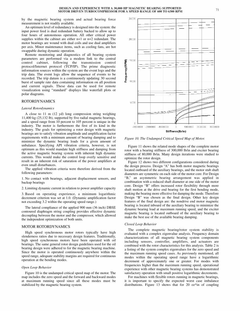
Open Loop Behavior
Figure 10 is the undamped critical speed map of the motor. Themap includes the zero speed and the forward and backward modesat maximum running speed since all these modes must bestabilized by the magnetic bearing system.
Figure 10. The Undamped Critical Speed Map of Motor.
Figure 11 shows the related mode shapes of the complete motorrotor with a bearing stiffness of 300,000 lb/in and exciter bearingstiffness of 80,000 lb/in. Many design iterations were studied tooptimize the rotor design.
Figure 12 shows two different configurations considered duringthe design process. Design “A” has both motor magnetic bearingslocated outboard of the auxiliary bearings, and the motor stub shaftdiameters are symmetric on each side of the motor core. For Design“B,” an asymmetric bearing arrangement was applied incombination with a reduced shaft diameter at one side of the motorcore. Design “B” offers increased rotor flexibility through moreshaft motion at the drive end bearing for the first bending mode,making the bearing more effective for damping the mode. ThereforeDesign “B” was chosen as the final design. Other key designfeatures of the final design are: the nondrive end motor magneticbearing is located inboard of the auxiliary bearing to minimize thedynamic bearing load at maximum running speed, and the excitermagnetic bearing is located outboard of the auxiliary bearing tomake the best use of the available bearing damping.
Closed Loop Behavior
The complete magnetic bearing/rotor system stability isevaluated with a complex eigenvalue analysis. Frequency domaincharacterizations of all magnetic bearing system componentsincluding sensors, controller, amplifiers, and actuators arecombined with the rotor characteristics for this analysis. Table 2 isa listing of the system complex eigenvalues for the zero speed andthe maximum running speed cases. As previously mentioned, allmodes within the operating speed range have a logarithmicdecrement of approximately one or greater. For modes withfrequencies higher than the maximum running speed, operationalexperience with other magnetic bearing systems has demonstratedsatisfactory operation with small positive logarithmic decrements.
For machines with flexible rotors running in magnetic bearings,it is important to specify the expected worst case imbalancedistributions. Figure 13 shows that for 20 oz*in of coupling

Figure 11. Mode Shapes of the Complete Motor Rotor.
Figure 12. Two Types of Rotor Bearing Designs Were Studied;Design “B” Was Finally Chosen.
imbalance, the drive end bearing comes close to the dynamic limitof 2.5 amps. An imbalance of 20 oz-in applied anywhere else onthe rotor results in much lower dynamic currents.
COMPRESSOR ROTORDYNAMICS
Because of the numerous design tradeoffs in the compressordesign, opportunities were limited for optimizing the rotor designfor the magnetic bearings: minimum low frequency dampingrequirement, minimum damping requirement at rigid body andbending modes, strong seal effects, large operating speed range,and small inherent shaft damping. The bearing stiffness also mustbe high enough to resist fluid forces both DC and AC in nature.
Open Loop Behavior
Figure 14 shows the calculated undamped critical speed map ofthe compressor.
Table 2. System Complex Eigenvalues Motor.
Figure 13. Unbalance Response at Main Coupling.
PROCEEDINGS OF THE 29TH TURBOMACHINERY SYMPOSIUM72
Rotational
Speed
0 RPM 6300 RPM
Mode
Description
Frequency(RPM)
Log.Dec.
Frequency(RPM)
BackwardForward
Log.Dec.
Translation 1014 1.78 10131015
1.751.80
Tilting 1460 2.63 13951525
2.632.62
RotorFirst
Flexible
2470 1.95 23732571
1.961.94
RotorSecondFlexible
3301 0.96 30813535
0.990.93
ControllerPole
5130 1.94 51295147
2.001.96
RotorThird
Flexible
7548 0.01 70708061
0.010.01
RotorFourth
Flexible
14967 0.01 14.38215.557
0.010.01
RotorFifth
Flexible
18801 0.01 18.19519.415
0.010.01
ControllerPole
33000 0.94 33.00033.000
0.930.95

DESIGN AND EXPERIENCE WITH A 30,000 HP MAGNETIC BEARING SUPPORTEDMOTOR DRIVEN TURBOCOMPRESSOR FOR A SPEED RANGE OF 600 TO 6300 RPM 73
Figure 14. The Undamped Critical Speed Map of the Compressor.
Table 3 lists the location of the natural frequencies for differentbearing stiffness both at standstill and at maximum continuous speed.The shift in natural frequency between standstill and full runningspeed indicates that the rotor has a gyroscopic effect that is caused bythe large diameter impellers and thrust disk, which have all beenmodeled as rigid connected masses with polar and transverse inertia.
Table 3. System Complex Eigenvalues Compressor.
Figure 15 shows the associated rotor mode shapes at standstill.All mode shapes of interest have acceptable controllability(amplitude at the bearing actuator position) and observability(amplitude at the sensor position).
Figure 15. Undamped Mode Shapes of Compressor Rotor atStandstill Indicate Controllability and Observability.
The eigenvalues (natural frequencies and damping ratio) of thecombined rotor bearing system at nominal speed and standstill arelisted in Table 3. All modes below maximum continuous speed arewell damped. The first bending mode has a logarithmic decrementclose to 1.0 (damping ratio D = 17.3 percent), which is close to theAPI 617 (1995) requirement. All modes below 800 Hz are stable.Above 800 Hz instability may occur, since the phase angle of thebearing then becomes negative. In reality, the internal damping ofthe rotor will most probably prevent these instabilities, since thenegative damping has a very small magnitude.
The closed loop response to an unbalance modal excitation forthe various critical speeds of interest has been evaluated. Theresponse is well damped throughout the operating speed rangefrom 600 to 6300 rpm. The maximum bearing forces are wellwithin the 2250 lb dynamic bearing capacity at 105 Hz.
Table 4 is the result of the stability analysis taking into accountfull aerodynamic excitation. It can be seen that stable operation ispredicted throughout the operating speed range.
Torsional Rotordynamics
The rotor train must be designed to withstand the torqueamplifications for startup, normal operation, and also for faultconditions. The main torsional excitation for the train is generatedby the current harmonics of the 12-pulse converter fed motor.Therefore it is necessary to choose a rotor design where the relativedeflection in the area of the rotor is low for the significant modeshapes.
Figure 16 shows the calculated undamped torsional criticalspeed mode shapes of the compressor string.
Rotational
Speed
0 RPM 6300 RPM
Mode
Description
Frequency(RPM)
Log.Dec.
Frequency(RPM)
BackwardForward
Log.Dec.
Translation 850 1.66 847853
1.661.66
Tilting 944 1.78 930958
1.781.78
ControllerPole
2148 1.12 21422154
1.101.14
Rotor1st Flexible
4870 1.05 46395082
1.081.01
ControllerPole
7788 0.39 77287848
0.430.35
ControllerPole
7811 0.55 77517871
0.480.62
Rotor2nd Flexible
9206 0.07 95969816
0.080.06
Rotor3rd Flexible
14960 0.01 1352016400
0.010.01
Rotor4th Flexible
21180 0.01 1890023460
0.010.01

Table 4. Stability Analysis of Compressor with Full AerodynamicExcitation.
Figure 16. Undamped Torsional Critical Speed Mode Shapes of theCompressor String.
The Campbell diagram (Figure 17) shows possible points ofresonance condition for steady-state operation.
Despite the direct drive configuration, it is technically not feasibleto remove all criticals from within the extremely wide operatingspeed range. The design of the rotor string (motor, coupling, andcompressor) is governed mainly by performance and the lateralbehavior of the individual string components. The first torsionalcritical speed can be adjusted by selective tuning of the coupling.
Stationary Resonance Analysis
All air gap pulsating torques appear in the center section of themotor. Figure 18 shows the system response in coupling andexciter shaft due to an exciting torque of 1000 Nm at the center ofthe rotor core and 1 percent critical damping. The stresses arerepresented in the coupling spacer and in the exciter coupling shaftas N/mm2.
Figure 17. Campbell Diagram with Possible Points of ResonanceCondition for Steady-State Operation.
Figure 18. Torque Response Due to Steady-State Excitation with1000 Nm at Midspan of Motor Core.
It can be recognized that the first resonance peak dominates thebehavior and represents the maximum stress amplification in thestring. A detailed fatigue analysis confirmed that the calculatedstresses are acceptable and continuous operation would bepossible. All further resonances have relatively low amplificationsand can be neglected.
Startup Analysis
During the startup process, various torsional naturalfrequencies are passed. Only the first one brings significantlyhigher stress in some sections of the shaft system: In the speedrange 2600 rpm ≤ n ≤ 3400 rpm, the first natural frequency isexcited four times (Figure 17). The result of a startup simulationis shown in Figure 19.
Fault Condition Analysis
The main electrical fault conditions are:
• Three-phase short circuit at the motor terminals
M(t) = 9.8.MN.e .sin(660.n.t) (1)
• Line-to-line short circuit at the motor terminals
PROCEEDINGS OF THE 29TH TURBOMACHINERY SYMPOSIUM74
Rotational
Speed
6300 RPM
Without Seal Effects
6300 RPM
With Seal Effects
ModeDescription
Frequency (rpm) Backward Forward
Log.Dec.
Frequency (rpm) Backward Forward
Log.Dec.
Translation 847 853
1.661.66
552 1152
6.380.31
Tilting 930 958
1.781.78
737 1024
4.360.67
RotorFirstFlexible
4639
5082
1.08
1.01
4716
5032
0.99
0.94
�t0.182

DESIGN AND EXPERIENCE WITH A 30,000 HP MAGNETIC BEARING SUPPORTEDMOTOR DRIVEN TURBOCOMPRESSOR FOR A SPEED RANGE OF 600 TO 6300 RPM 75
Figure 19. Runup Through Resonance with Nominal Torque PosesNo Danger to the Rotating String.
M(t) = 9.8.MN. (2)
where n is the actual rotating speed divided by the reference speednN = 6300 rpm.
It can be seen that the frequency of the short circuit excitation isa function of the actual motor speed. The worst condition is whenthe excitation frequency coincides with one of the naturalfrequencies of the drive train, whereby the most critical torsionalmodes are the first and the second one where the motor shaft has acertain amplitude at the motor core. The calculated short circuitresponse is shown in Figures 20 and 21. In looking at these faultscenarios, however, one has to consider the extreme unlikeliness ofsuch an event in actual installations. Nevertheless, precautions inthe form of controlled-slip fits and shear points are installed tomitigate this risk.
Figure 20. Two-Phase Short Circuit at 1530 RPM.
Figure 21. Three-Phase Short Circuit at 1530 RPM.
The detailed damped response calculations, both steady-stateand transient, confirmed that continuous operation over theextreme wide operation range from 600 to 6300 rpm is feasible.Beneficial in this respect was the inertia split of the largesynchronous motor and the compressor.
The calculated stress levels were all well within the acceptancelimit.
TESTING
Motor
Basic motor rotordynamics were established through modalanalysis with the rotor supported vertically from a crane. Statictuning of the assembled motor rotor was done followed by highspeed balancing of the motor rotor in its magnetic bearings.
Various balancing planes enable a modal balancing of thefinished rotor. The motor rotor was not high speed balanced on abalance stand, but directly in its magnetic bearings since allbalancing planes were readily accessible. This was followed byunbalance response sensitivity checks indicating that the motorresponded very well.
Field experience on this class of electric motors indicates that,once balanced, deterioration of the balance quality is notanticipated. However, different from a centrifugal compressor, themotor rotor must handle electromagnetic pull from both the exciterand main motor stator section, as well as thermal gradients duringstartup and changing operating conditions. This introducessignificant dynamic loads that have to be taken into account. Anextensive test program was set up to verify the integrity of thedesign. The applied concept of separate base frames for motor andcompressor, the lateral compliance of the interconnectingcoupling, and dedicated magnetic bearing controllers allowedsimultaneous execution of this test program at both the compressorand the motor supplier’s works.
The sensitivity to imbalance for the motor rotor/bearing systemwas measured over the running speed range. Figures 22, 23, and 24show the comparison between the measured values and thecalculated values for the imbalance case of 20 oz*in applied out-of-phase at each rotor core end cap. The calculated values are ingood agreement with the measured values.
Static and dynamic tuning were completed in a straightforwardmanner with no problems. This was attributed to the optimizedmotor rotor design, the significant internal damping inherent withthese types of rotors, and use of the experiences related to thecontrol system software gained at the compressor supplier works.
Compressor
The compressor rotor was high speed balanced in oil bearings.Dedicated shaft sleeves replaced the contract laminated sleeves for
� �e .sin(660.n.t)
�0.5.e .sin(2.660.n.t)
�t0.097
�t0.306
�2.t0.306

Figure 22. Drive End Bearing—Unbalance Response Out-of-Phase at Motor Core End Caps.
Figure 23. Non Drive End Bearing—Unbalance Response Out-of-Phase at Motor Core End Caps.
Figure 24. Exciter Bearing—Unbalance Response Out-of-Phase atMotor Core End Caps.
this purpose. The basic rotordynamics were verified using modalanalysis with the rotor supported horizontally in slings. Statictuning of the assembled compressor was done with the dry gasseals and labyrinths removed. Soon it became evident that thetargeted magnetic bearing control strategy would not be adequatefor this unit. A high frequency mode at 490 Hz interfered with theroll-off region of the controller. Interim high order filters were triedbut none were successful. It was concluded that more testing wouldbe required to get a better understanding of what was going on. Therotor was sent back to the balancing bunker and the disk behaviorwas recorded during a full operating speed range run undervacuum. It became evident that the disk had several disk modeswithin the frequency range of interest caused by its slender naturedesign. Detailed analytical checks using FEA confirmed that the
disk had a nodal diameter vibration mode at approximately 490Hz, which had to be considered in the rotor model (Figure 25).
Figure 25. FEA Compressor Mode Shape at 490 Hz.
Figure 26. Revised Undamped Critical Speed Map of Compressorwith Compressor Disk Fixed to the Rotor by a Rotational Spring toMeet the 490 Hz.
To model this mode, the disk was fixed to the rotor with arotational spring. The stiffness of this spring was adjusted to yieldthe 490 Hz. The results are plotted in Figure 26.
It can be seen that the disk mode and the rotor modes areinteracting. In the second and higher bending modes, the flexibledisk tilts more than a rigid disk would. This has the effect ofconsiderably increasing the gyroscopic effect. As a consequence,the frequency difference between forward and backward whirl alsoincreases and thus the frequency regions where the bearing has toprovide damping. This explained why the initial control strategydid not work out as predicted. A revised control strategy wasselected and implemented, and static tuning was completedsuccessfully before the unit was prepared for dynamic testing.
The compressor was admitted to an unbalance sensitivity test.Unbalance weights were placed at both the thrust disk and thecoupling location. Bearing response to an in-phase G2 unbalance(3300 g (117 oz) at the thrust disk, and 2700 g (95 oz) at thecoupling) is shown in Figure 27.
It can be seen that the measured response is in good agreementwith the prediction and furthermore that the absolute magnitude iswell within the bearing load capacity. To mimic a dry gas sealmaintenance cycle, the magnetic bearing components weredisassembled and then reassembled. The response was checkedand it matched the original.
PROCEEDINGS OF THE 29TH TURBOMACHINERY SYMPOSIUM76

DESIGN AND EXPERIENCE WITH A 30,000 HP MAGNETIC BEARING SUPPORTEDMOTOR DRIVEN TURBOCOMPRESSOR FOR A SPEED RANGE OF 600 TO 6300 RPM 77
Figure 27. Unbalance Response Test of the Compressor.
A 12 MW, part load, full speed hydrocarbon test was one ofseveral executed. The inhouse high pressure natural gas gridconnection at the supplier’s works allowed the use of basicallyClass I conditions. Test results are shown in Figure 28 and it can beseen that an excellent match is yielded compared to the prediction.During these tests, the magnetic bearing control system recordedlow frequency, forced vibrations when operating the unit underturndown conditions at high speed. Dynamic pressure pulsationmeasurements cohered well with these recordings, confirming thatthese vibrations were forced by aerodynamic excitation most likelycaused by off-design operation at these high speeds. However, themagnitude of the pressure pulsation was only in the mbar region.The recorded sensitivity was explained by the lower stiffness of themagnetic bearings compared to oil bearings at these lowfrequencies.
During testing, the rotor was subjected to a nonlevitatedrundown from full speed down to approximately 3000 rpm.
Following this test, the backup bearings were checked and foundin excellent condition. Some material transfer from the stator padlining to the sleeve on the rotor was observed, which is inherentwith the design used here. During this test, a high dynamic loadwas imposed on the rotor that was believed to simulate an extremeunbalanced rundown situation. The observations and measure-ments afterward confirmed that the landing system was fit forpurpose.
Figure 28. Full Speed, Part Load (12 MW) Hydrocarbon Test ofCompressor.
FIELD EXPERIENCE
The equipment was shipped to site in the summer of 1998 andhooked up to the cluster. The motor was initially run solo.Everything proved satisfactory and the interconnecting couplingwas installed. The axial magnetic bearing controller was tested forthe first time with the motor and compressor joined by the highaxial stiffness coupling. Axial dynamic testing to verifysatisfactory performance of the axial bearing controller wascompleted in a day, and the unit was run to full speed usingnitrogen. As expected, the lateral compliance of the couplingprovided sufficient dynamic isolation between the two machines sono changes were required in the radial bearing algorithms. Allparameters proved satisfactory and the unit was submitted to a fullload/full speed test on the actual natural gas. Cluster limitationsenabled maximum operation up to 23 MW at 5700 rpm with theunit in recycle mode—the test was passed flawlessly.
The torsional behavior of the unit was verified by means of atorque measuring device integrated in the coupling spacer. Themeasured first natural frequency is 27.5 Hz and has a lowdamping of about 1 percent. During normal operating conditions,only vibration with that first critical frequency occurred.Alternating torques during startup with low speed ramp reachtheir maximum of less than 15 percent of nominal torque atspeeds of 2728, 2864, 3136, and 3272 rpm, coinciding with theresonance points of the Campbell diagram (Figure 17). Figure 29shows a waterfall plot of the exciting torque pulsation in the airgap of the motor derived from measured electrical data duringslow startup.
Figure 29. Measured Exciting Air Gap Torque Pulsation DuringSlow Startup.
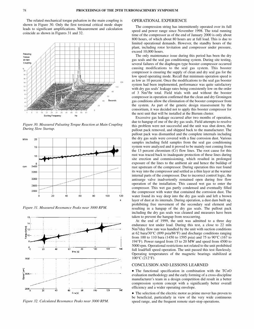
The related mechanical torque pulsation in the main coupling isshown in Figure 30. Only the first torsional critical mode shapeleads to significant amplifications. Measurement and calculationcoincide as shown in Figures 31 and 32.
Figure 30. Measured Pulsating Torque Reaction at Main CouplingDuring Slow Startup.
Figure 31. Measured Resonance Peaks near 3000 RPM.
Figure 32. Calculated Resonance Peaks near 3000 RPM.
OPERATIONAL EXPERIENCE
The compression string has intermittently operated over its fullspeed and power range since November 1998. The total runningtime of the compressor as of the end of January 2000 is only about800 hours, of which about 80 hours are at full load. This is due tolimited operational demands. However, the standby hours of theplant, including rotor levitation and compressor under pressure,exceed 10,000 hours.
The only maintenance issue during this period has been the drygas seals and the seal gas conditioning system. During site testing,several failures of the diaphragm type booster compressor occurredcausing modifications to the seal gas system. This boostercompressor is ensuring the supply of clean and dry seal gas for thelow speed operating mode. Recall that minimum operation speed isas low as 10 percent. Once the modifications to the seal gas boostersystem had been implemented, performance was quite satisfactorywith dry gas seals’ leakage rates being consistently low on the orderof 3 Nm3/hr total. Field trials with and without the boostercompressor in operation confirmed that the clean and dry Groningengas conditions allow the elimination of the booster compressor fromthe system. As part of the generic design reassessment by theconsortium, it was decided not to apply this booster compressor forthe next unit that will be installed at the Bierum cluster.
Excessive gas leakage occurred after two months of operation,due to hangup of one of the dry gas seals. Field attempts to resolvethis problem were not successful and the unit was shut down, thepullout pack removed, and shipped back to the manufacturer. Thepullout pack was dismantled and the complete internals includingthe dry gas seals were covered with a fine corrosion dust. Varioussamples including field samples from the seal gas conditioningsystem were analyzed and it proved to be mainly rust coming fromthe 13 percent chromium (Cr) flow lines. The root cause for thisrust was traced back to inadequate protection of these lines duringsite erection and commissioning, which resulted in prolongedexposure of the lines to the ambient air and hence the buildup ofrust upstream of the compressor. During operation this rust foundits way into the compressor and settled as a thin layer at the warmerinternal parts of the compressor. Due to incorrect control logic, theantisurge valve inadvertently remained open during free flowoperation of the installation. This caused wet gas to enter thecompressor. This wet gas partly condensed and eventually filledthe compressor with water that contained the corrosion dust. Thewater found its way deep into the dry gas seals and left a brownlayer of dust at its internals. During operation, a dust dam built up,prohibiting free movement of the secondary seal element andresulting in a hangup of the dry gas seals. The pullout packincluding the dry gas seals was cleaned and measures have beentaken to prevent the hangup from reoccurring.
At the end of 1999, the unit was admitted to a three dayendurance test under load. During this test, a close to 22 mlnNm3/day flow rate was handled by the unit with suction conditionsat 62 bara/30°C (899 psia/86°F) and discharge conditions rangingfrom 100 to 110 bara (1450 to 1595 psia) and 75 to 90°C (167 to194°F). Power ranged from 15 to 20 MW and speed from 4500 to5000 rpm. Operational restrictions not related to the unit prohibitedfull load/full speed operation. The unit passed this test flawlessly.Operating temperatures of the magnetic bearings stabilized at100°C (212°F).
CONCLUSION AND LESSONS LEARNED
• The functional specification in combination with the TCoOevaluation methodology and the early forming of a cross-disciplinemanufacturer’s team in a design competition did result in a bettercompression system concept with a significantly better overallefficiency and a wider operating envelope.
• The selection of the electric motor as prime mover has proven tobe beneficial, particularly in view of the very wide continuousspeed range, and the frequent remote start-stop operations.
PROCEEDINGS OF THE 29TH TURBOMACHINERY SYMPOSIUM78
DESIGN AND EXPERIENCE WITH A 30,000 HP MAGNETIC BEARING SUPPORTEDMOTOR DRIVEN TURBOCOMPRESSOR FOR A SPEED RANGE OF 600 TO 6300 RPM 79
• Annual natural gas savings are expected on the order of 14 mlnNm3 per cluster compared with a traditional gas turbine solution.
• Absence of routine maintenance and consequential minimumhuman intervention on the compression string and low noiseemissions allow for the omission of a compressor building,associated safety systems, and stationary cranes.
• The integrated design approach of compressor, motor, andbearing manufacturers is essential for such new developments anddesigns, particularly with an all magnetic bearing solution.
• Reliable operation of magnetic bearings throughout a very widespeed range including operation on lateral critical speeds has beenproven.
• There still is a need to further simplify and improve dry gas sealsystems. Initial field experience has shown that, by virtue of theclean and dry gas conditions at the compressor suction, the seal gasbooster compressors can be eliminated on future joint ventureinstallations.
• API should develop a comprehensive set of design guidelinesand performance requirements for the use of magnetic bearings inhigh speed turbomachinery. This will ensure the correct applicationand take due account of the inherent benefits of magnetic bearings.
REFERENCES
API Standard 614, 1999, “Lubrication Shaft-Sealing and Control-Oil Systems for Special-Purpose Applications,” AmericanPetroleum Institute, Washington, D.C.
API Standard 617, 1995, “Centrifugal Compressors for Petroleum,Chemical, and Gas Service Industries,” Sixth Edition,American Petroleum Institute, Washington, D.C.
ASME PTC-10, 1997, “Compressor and Exhausters,” AmericanSociety of Mechanical Engineers, New York, New York.
ACKNOWLEDGEMENT
The authors wish to acknowledge the support andencouragement of the owners/operators of the subject installation,Nederlandse Aardolie Maatschappij B.V. (NAM), and theassistance and contributions of Dr. Günther Siegl and HartmutRauch, Siemens Dynamowerk Berlin; Fritz Kleiner, Siemens Oil &Gas Division Erlangen; and Viv Fletcher, Federal Mogul MagneticBearings, Shoreham-by-Sea, United Kingdom.

PROCEEDINGS OF THE 29TH TURBOMACHINERY SYMPOSIUM80