design, construction and introduction of artificial dna...
TRANSCRIPT
Design, construction and introduction of artificial DNA
encoding a FeFe hydrogenase into unicellular
cyanobacterial cells
Ravi Raj Amatya
Degree project in Applied Biotechnology, Master of Science (2 years), 2012
Examensarbete i 45 hp till masterexamen, 2012
Biology Education Centre and Department of Photochemistry and Molecular
Science, Ångstrom, Uppsala University.
Supervisor: Peter Lindblad and Elias Englund
Contents
Abstract 1
Abbreviations 2
Objective 3
Introduction 4
Biofuel 4
Synthetic biology for biofuels 4
Hydrogen as biofuel 5
Biohydrogen 5
Hydrogenases 6
Cyanobacteria 8
One step isothermal DNA assembly (G s ’s ss y h ) 9
Project plan 11
Material and Method 14
Results 26
Discussion 32
Acknowledgement 33
References 34
1
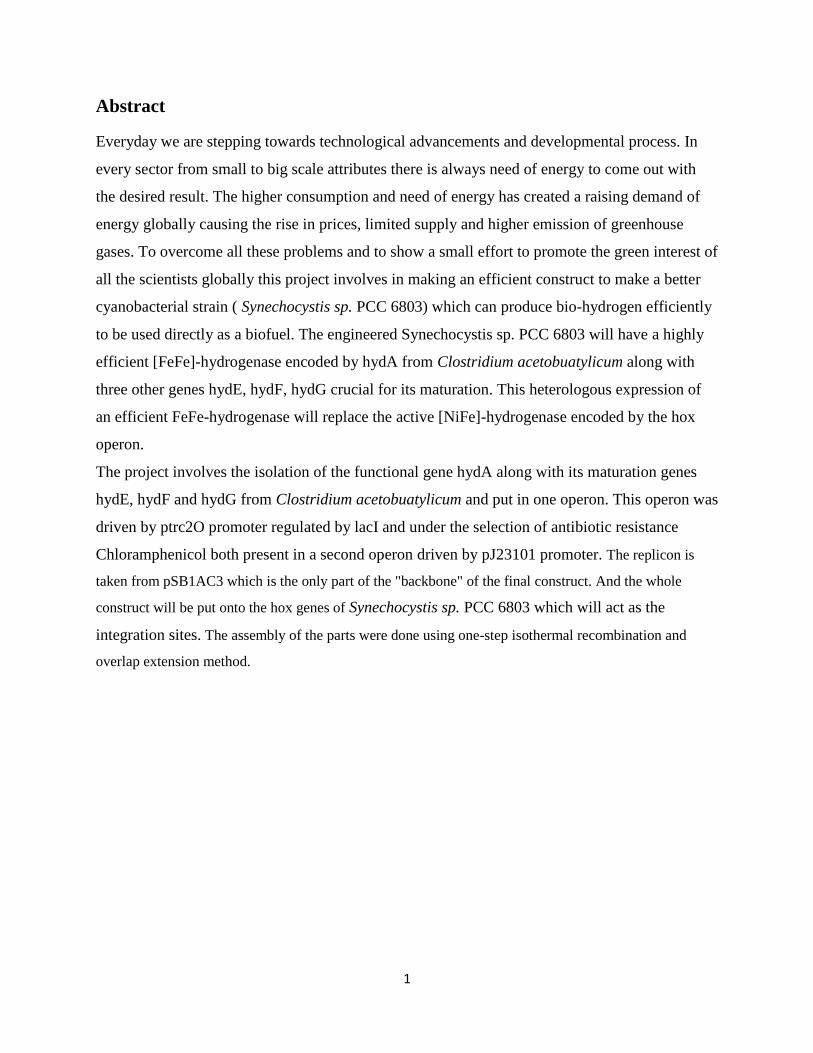
Abstract
Everyday we are stepping towards technological advancements and developmental process. In
every sector from small to big scale attributes there is always need of energy to come out with
the desired result. The higher consumption and need of energy has created a raising demand of
energy globally causing the rise in prices, limited supply and higher emission of greenhouse
gases. To overcome all these problems and to show a small effort to promote the green interest of
all the scientists globally this project involves in making an efficient construct to make a better
cyanobacterial strain ( Synechocystis sp. PCC 6803) which can produce bio-hydrogen efficiently
to be used directly as a biofuel. The engineered Synechocystis sp. PCC 6803 will have a highly
efficient [FeFe]-hydrogenase encoded by hydA from Clostridium acetobuatylicum along with
three other genes hydE, hydF, hydG crucial for its maturation. This heterologous expression of
an efficient FeFe-hydrogenase will replace the active [NiFe]-hydrogenase encoded by the hox
operon.
The project involves the isolation of the functional gene hydA along with its maturation genes
hydE, hydF and hydG from Clostridium acetobuatylicum and put in one operon. This operon was
driven by ptrc2O promoter regulated by lacI and under the selection of antibiotic resistance
Chloramphenicol both present in a second operon driven by pJ23101 promoter. The replicon is
taken from pSB1AC3 which is the only part of the "backbone" of the final construct. And the whole
construct will be put onto the hox genes of Synechocystis sp. PCC 6803 which will act as the
integration sites. The assembly of the parts were done using one-step isothermal recombination and
overlap extension method.
2
Abbreviations
Ori Origin of replication
bp base pairs
dH2O deionized sterilized water.
DNA deoxyribonucleic acid
dsDNA double stranded DNA
hyd hydrogenase
dNTPs deoxyribonucleotides
kb kilo base pairs
LB lysogeny broth (Luria-Bertani medium)
PCR polymerase chain reaction
U units of enzyme
X-gal bromo-chloro-indolyl-galactopyranoside
IPTG Isopropyl β-D-1-thiogalactopyranoside
TAE Tris base, acetic acid and EDTA
PCC Pasteur culture collection
e-
electron
Cm Chloramphenicol

3
Objective
Th j c v f h s s r’s h s s s c s ruc r f c DNA h c s f r
highly efficient [FeFe]-hydrogenase encoded by hydA from Clostridium acetobuatylicum along
with its three maturation genes hydE, hydF, hydG and introduce them into Synechocystis sp.
PCC6803 by homologous recombination to replace their native [NiFe]-hydrogenase system. This
heterologous recombination has been shown to produce hydrogen (H2) with rate 500 times that
of the native [NiFe]-hydrogenase system in the unicellular cyanobacteria, Synechocystis (Ducat,
Sachdeva, & Silver, 2011).
4
Introduction
Biofuel
Biofuels, also known as agro-fuels are the renewable fuels mainly produced from biomass or
metabolic byproducts like food or organic wastes. They are mostly biodegradable and non-toxic
in nature. Biofuel can be produced from any carbon source using the photosynthetic plant for
production where energy is derived from the biological carbon fixation (http://www.alternative-
energy-news.info/technology/biofuels/). Biofuel is the best solution as an alternative fuel against
the conventional fossil fuels which have limited avaibility and also to reduce the emission of
greenhouse gases. The interest of global scientific community has increased highly on the matter
of biofuel because of the drawbacks of fossil fuels like limited availability, raise in price, and
environmental pollution (http://biofuel.org.uk/).
Currently two major sources of biofuels are in use. In the first method fermentation is carried out
where ethanol is produced from the sugar crops or starch like sugarcanes, soybeans, corns etc.
The second method involves green algae and plants like jatropha which are grown naturally to
produce oil and can be used directly as fuel for diesel engines. The major producers and users of
the biofuel in the present day context are Asia, Europe and America. United States of America
uses soybean and corn to produce ethanol while Brazil and Asian countries use sugarcane to
produce ethanol. Similarly Europe uses sugar beet and wheat to produce ethanol and in India
they use palm oil and oil from jatropha plant as fuel (http://biofuel.org.uk/).
Synthetic biology for biofuels
Use of synthetic biology enables to choose various properties of different genes freely from the
DNA library and assemble them in an expressible combination to make a novel biological
system or organism with the desired properties which will finally lead to the desired product. The
use of synthetic biology makes it possible to design, engineer and implement new biological
system which might not exist in the nature or re-design the existing ones to make them more
useful and efficient. Synthetic biology these days has been used much frequently and efficiently
in the field of pharmaceuticals for drug production, design of biosensors, bioremediation and
biofuel production.
In the field of biofuel production, synthetic biology has become very promising by creating the
possibilities of construction of efficient novel pathways for different biofuels like ethanol,

5
butanol, hydrogen, etc. In my project I am using synthetic biology to design and make a novel
construct for photo production of hydrogen using cyanobacteria.
Hydrogen as fuel
H2 is one of the major potential renewable future bio-fuel to replace fossil fuel and switch off the
global warming. It is the only fuel known so far with almost zero emission and hence known as
the cleanest fuel available till date. It is the most abundant h E r h’s v r
and exists in nature as compounds in combination with other elements. To use up the H2 as fuel it
must exist as free Hydrogen (H2) (Sarma, Brar, Le Bihan, & Buelna, 2012).
When used as fuel H2 works as energy carrier and the energy is delivered as heat when it is
combusted. The specially designed engine system converts the chemical energy of H2
to mechanical energy by burning H2 in an internal combustion engine or by reacting H2 with O2
in a fuel cell to run electric motors. The use of H2 fuel has already been done in space rockets, as
well as automobiles (Melis & Happe, 2001).
Bio-hydrogen
Biohydrogen production is among one of the most challenging areas in biotechnology for the
scientists and researchers who are working for the alternative fuel to contribute to the global
energy crisis. Biohydrogen is one of the promising renewable source of energy which can be
produced from renewable feedstocks like biomass or biowastes by biochemical or biophotolytic
process and hence known as clean and environmently friendly fuel (Allakhverdiev et al., 2009).
The microorganisms involved in biohydrogen production use this biomass as a source of
electrons and convert the energy into production of molecular H2 by one of the following
biological processes.
●Biophotolysis
●I r c h ys s
●Ph -fermentation
●D r f r
Phototrophic organisms like green algae and cyanobacteria can efficiently produce biohydrogen
via biophotolytic reactions. The biophotolytic reaction involves a photosynthesis process where
water molecules are split into protons, electrons and O2 molecules when light is received. The

6
protons are then reduced by combining with electrons with the help of hydrogenase enzyme to
from molecular H2.
Photosynthesis reaction:
2H2O → 4H+ + 4e
- + O2
Hydrogen production reaction:
4H+ + 4e
- → 2H2 + 2e
-
The fermentation of the biomass substrate is accompanied by inoculation of the microbial strain
which can efficiently convert biomass to molecular hydrogen driven by pyruvate metabolism.
This process causes the release of stored energy through fermentation of endogenous
carbohydrates and as a result protons are reduced by hydrogenase enzyme to form molecular H2
(Angermayr, Hellingwerf, Lindblad, & de Mattos, 2009).
Hydrogenases
Hydrogenases are the class of metalloproteins that catalyses the reversible oxidation of
molecular hydrogen (H2) (Berto et al., 2011).
2H+ + 2e
- H2
The hydrogenases catalyze this redox reaction with an equilibrium constant dependent on the
reducing potential of the electrons which are carried along by their redox partner. (Ducat et al.,
2011) Reportedly two main classes of hydrogenases are found in wide variety of organisms
depending upon the metallic cluster found in their catalytic sites. Namely they are: [NiFe]
hydrogenase and [FeFe] hydrogenase. Although the redox machinery of both hydrogenases
catalyses the same reaction, still there is distinct difference between both hydrogenases on their
structural basis, metallic cluster found in their active site and the electron carriers involved in
redox chemistry (Ducat et al., 2011).
[NiFe] hydrogenase
[NiFe] hydrogenases are found in archea and eubacteria including cyanobacteria (Berto et al.,
2011). The x-ray crystallography shows that [NiFe]-hydrogenase is heterodimer in structure with
active site residing in the large subunit. The active site contains Nikel and Iron ion which has
carbon monoxide and cyanide molecules serving as ligands bound to the Iron ion. Various iron-
sulfur clusters are present in the small subunit of enzyme which serve as electron transfer

7
cofactors (Horch, Lauterbach, Lenz, Hildebrandt, & Zebger, 2012).
Figure 1. X-ray crystallographic structure and active site of [Ni-Fe] hydrogenage (Ludwig, Cracknell, Vincent,
Armstrong, & Lenz, 2009)
[FeFe] hydrogenase
[FeFe]-hydrogenase are found only in eukaryotice microbes and a few prokaryotes but are not
present in any of the cyanobactera investigated y’s (Ducat et al., 2011). The active
site contains two iron ions each coordinated by a terminal carbonyl and a terminal cyanide
molecules serving as ligands. Various accessory iron-sulfur clusters are present in the
catalytically active site working as cofactors. These iron-sulfur clusters are thought to play an
important role in efficient electron transfer to and from the H-cluster (Schwab et al., 2006).
Figure 2. X-ray crystallographic structure and active site of [Fe-Fe] hydrogenage (Ludwig et al., 2009)
8
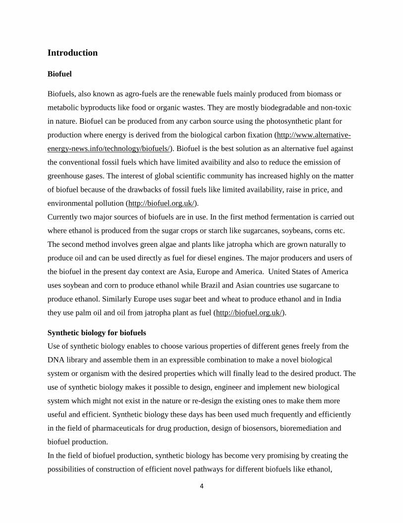
[FeFe]-hydrogenase are coupled with ferredoxin protein that can bear electrons with low
reduction potential of about -420 mV which is closer to the value of H2/H+
pair. [NiFe]-
hydrogenases which is coupled to electron carrying partner NADH has reducing potential
+320mV which states that [FeFe]-hydrogenase thermodynamically favors the hydrogen
production over the previous one. In a research when [FeFe]-hydrogenase encoded by HydA
from Clostridium acetobutylicum was heterogously expressed in non-nitrogen fixing
cyanobacteria Synechococcus elongatus sp. 7942 then the rate of hydrogen gas produced was
more than that produced by the native [NiFe]-hydrogenases. This explains the higher efficiency
of [FeFe]-hydrogenase over [NiFe]-hydrogenases when expressed heterologously in
cyanobacterial system (Ducat et al., 2011).
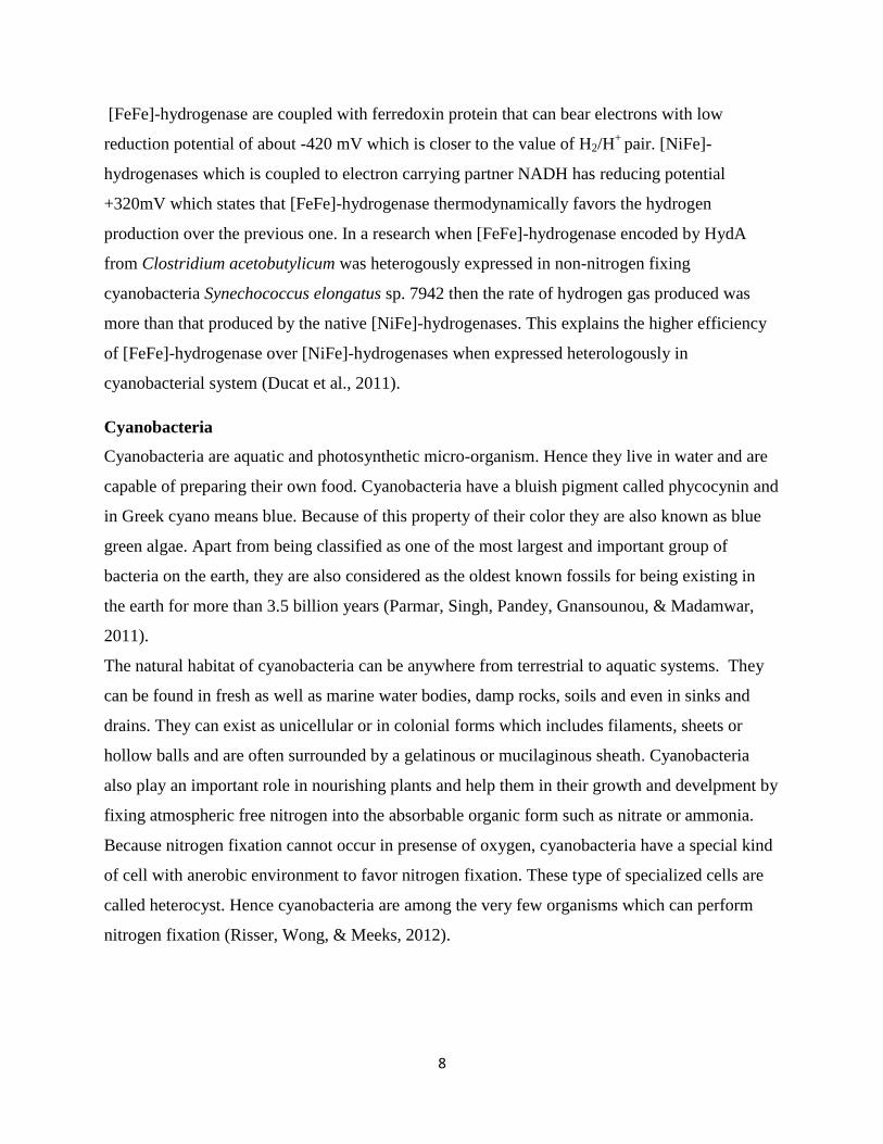
Cyanobacteria
Cyanobacteria are aquatic and photosynthetic micro-organism. Hence they live in water and are
capable of preparing their own food. Cyanobacteria have a bluish pigment called phycocynin and
in Greek cyano means blue. Because of this property of their color they are also known as blue
green algae. Apart from being classified as one of the most largest and important group of
bacteria on the earth, they are also considered as the oldest known fossils for being existing in
the earth for more than 3.5 billion years (Parmar, Singh, Pandey, Gnansounou, & Madamwar,
2011).
The natural habitat of cyanobacteria can be anywhere from terrestrial to aquatic systems. They
can be found in fresh as well as marine water bodies, damp rocks, soils and even in sinks and
drains. They can exist as unicellular or in colonial forms which includes filaments, sheets or
hollow balls and are often surrounded by a gelatinous or mucilaginous sheath. Cyanobacteria
also play an important role in nourishing plants and help them in their growth and develpment by
fixing atmospheric free nitrogen into the absorbable organic form such as nitrate or ammonia.
Because nitrogen fixation cannot occur in presense of oxygen, cyanobacteria have a special kind
of cell with anerobic environment to favor nitrogen fixation. These type of specialized cells are
called heterocyst. Hence cyanobacteria are among the very few organisms which can perform
nitrogen fixation (Risser, Wong, & Meeks, 2012).
9
Figure 3. Filamentous cyanobacteria Figure 4. Rod shaped Cyanobacteria
Synechocystis sp. PCC 6803
Synechocystis is a modular cyanobacterial strain which is capable of both phototrophic and
heterotrophic growth. Phototrophic growth is accompanied by oxygenic photosynthesis during
sunlight and heterotrophic growth is accompanied via glycosis and oxidative phosphorylation in
dark conditions. The strain was discovered in 1968 from a fresh water lake. It was then isolated
and put in the Pasteur culture collection (PCC). It is one of the model organism used by
scientists globally. It can survive in wide range of environmental conditions, can integrate any
foreign DNA into its genome via homologous recombination and hence favors spontaneous
transformation (http://synechocystis.asu.edu/).
One step isothermal assembly of overlapping dsDNA (Gibson DNA assembly method)
Because of the same fundamental chemical structure of DNA in all the living organisms, the
invention of molecular cloning techniquess made it possible to isolate different genes from
different organisms and put them together to work in a single system. The classical cloning
techniques make the use of DNA fragments of interest, restriction enzymes to cut the combining
ends and the enzyme ligase to join them together to form a new combination which may or may
not exist in nature.
G s ’s DNA ss y h s h us f c g h ff r r ch wh ch
can favor the recombination of multiple DNA fragments in just one isothermal reaction. The
number of DNA fragments to be combined can be more than a dozen and the combined DNA
fragments can be much larger as 583 kb. The process makes the use of the specific primers
which will eventually lead to the PCR products having overlapping sequences between every
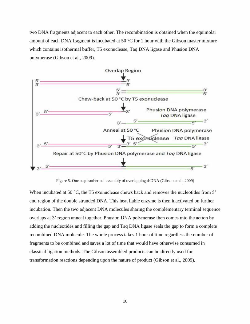
10
two DNA fragments adjacent to each other. The recombination is obtained when the equimolar
amount of each DNA fragment is incubated at 50 °C for 1 hour with the Gibson master mixture
which contains isothermal buffer, T5 exonuclease, Taq DNA ligase and Phusion DNA
polymerase (Gibson et al., 2009).
Figure 5. One step isothermal assembly of overlapping dsDNA (Gibson et al., 2009)
When incubated at 50 °C, the T5 ex uc s ch ws c r v s h uc s fr 5’
end region of the double stranded DNA. This heat liable enzyme is then inactivated on further
incubation. Then the two adjacent DNA molecules sharing the complementary terminal sequence
overlaps at 3’ r g g h r. Phus DNA y r s h c s h c y
adding the nucleotides and filling the gap and Taq DNA ligase seals the gap to form a complete
recombined DNA molecule. The whole process takes 1 hour of time regardless the number of
fragments to be combined and saves a lot of time that would have otherwise consumed in
classical ligation methods. The Gibson assembled products can be directly used for
transformation reactions depending upon the nature of product (Gibson et al., 2009).
11
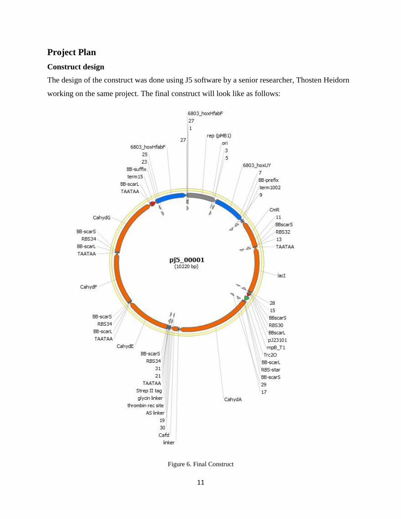
Project Plan
Construct design
The design of the construct was done using J5 software by a senior researcher, Thosten Heidorn
working on the same project. The final construct will look like as follows:
Figure 6. Final Construct
12
The final construct will consist of two flanking regions hoxUY and hoxHfab native to the
Syenchosists sp. 6803 and everything in between these two regions will be heterologously
inserted in the hoxUY and hoxHfab of Synechosists to replace the native NiFe hydrogenase
system. An origin of replication, Ori for replication of the plasmid which gives the high copy
number is obtained from pSBIAC3 plasmid and is present in between two flanking regions in the
construct.
The construct consists of a Chloramphenicol antibiotic cassette which will provide the criteria
for selection, a lacI repressor for the IPTG inducible promoter, a CahydA gene which codes for
hydrogenase enzyme important for hydrogen gas production, a streptavidin tag for the
purification of hydrogenase enzyme and CahydE, CahydF, CahydG genes for proper folding and
maturation of hydrogenase enzyme.
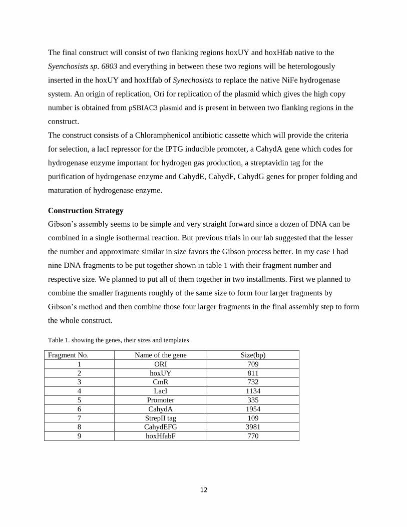
Construction Strategy
G s ’s ss y seems to be simple and very straight forward since a dozen of DNA can be
combined in a single isothermal reaction. But previous trials in our lab suggested that the lesser
the number and approximate similar in size favors the Gibson process better. In my case I had
nine DNA fragments to be put together shown in table 1 with their fragment number and
respective size. We planned to put all of them together in two installments. First we planned to
combine the smaller fragments roughly of the same size to form four larger fragments by
G s ’s h and then combine those four larger fragments in the final assembly step to form
the whole construct.
Table 1. showing the genes, their sizes and templates
Fragment No. Name of the gene Size(bp)
1 ORI 709
2 hoxUY 811
3 CmR 732
4 LacI 1134
5 Promoter 335
6 CahydA 1954
7 StrepII tag 109
8 CahydEFG 3981
9 hoxHfabF 770
13
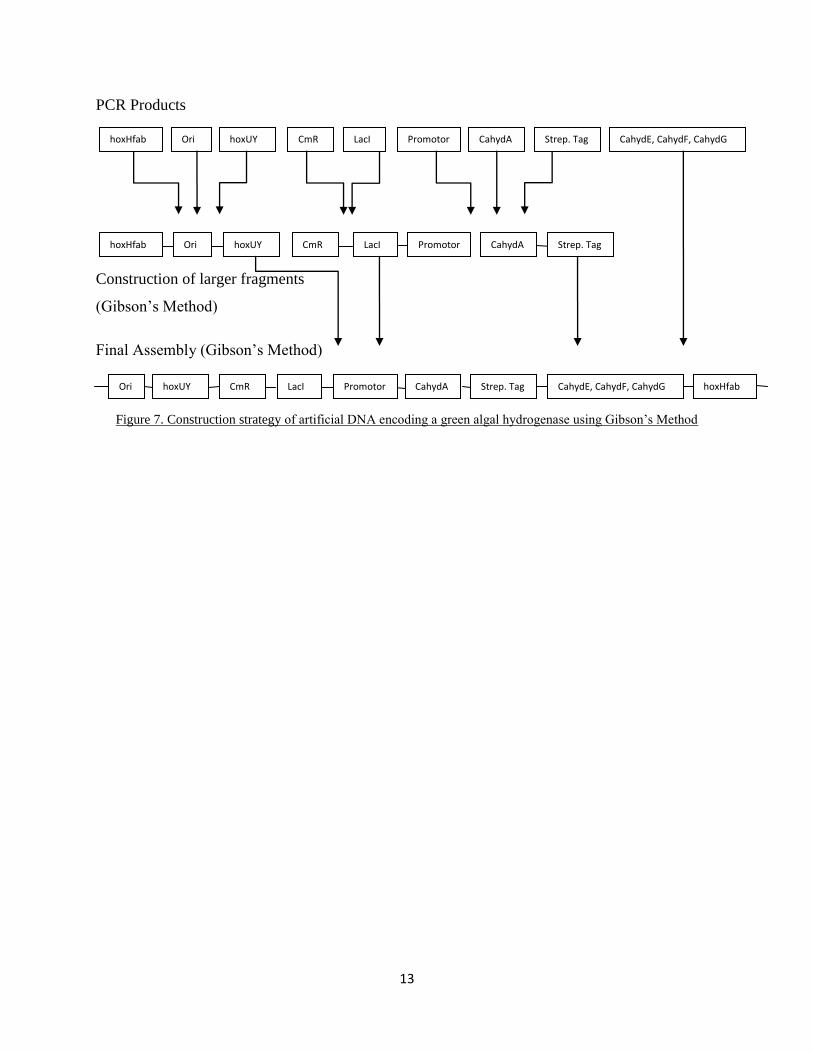
PCR Products
Construction of larger fragments
(G s ’s M h )
F Ass y (G s ’s M h )
Figure 7. Construction strategy f r f c DNA c g gr g hy r g s us g G s ’s M h
Ori hoxUY CahydE, CahydF, CahydG CahydA LacI CmR hoxHfab
hoxHfab Ori hoxUY CmR LacI CahydA
hoxHfab Ori hoxUY CmR CahydA CahydE, CahydF, CahydG
Promotor
r
Strep. Tag
Strep. Tag Promotor
rr
Promotor
rr
Strep. Tag LacI

14
Materials and Methods
1. Chemicals used
Finnzymes Phusion® Hot Start II, High-Fidelity DNA Polymerase was used for all the PCR
amplification reactions. Finnzymes Phusion® DNA Polymerase was used for all the Gibson
assembly and Overlap extention reaction. T5 exonuclease and Taq DNA ligase from Thermo
Scientific w s us f r ch w g DNA fr 5’ s g h c r s c v y G s ’s
assembly method. dNTP mix containing equimolar concentration of all four dNTs were obtained
from Finnzymes. Dream Taq DNA Polymerase obtained from Fermentas was used for colony
PCR. DNA primers (oligonucleotides) for all PCR amplifications and sequencing the DNA
samples were purchased from Eurofins MWG operon. The purification of PCR amplified
product and DNA extraction from gel was done using GeneJETTM
PCR purification Kit and
GeneJETTM
gel extraction kit respectively. The plasmid prepration from the culture was done
using GeneJETTM
plasmid mini prep kit.
2. Organisms used
Escherichia coli strain DH5α was used to make competent cells which was frequently used for
transformation. Synechosystis sp. 6803 was used to amplify the hoxUY and hoxHfabF (flanking
regions of the whole construct) which will be used to transform the whole construct in it by
heterologous recombination.
3. Vectors used
pBluescript II KS- vector
pBluescript II KS- is a commercially available phagmid with 2961 bp in length. As shown in
figure 8 it consist of intergenic region of phage F1, replicon pMB1 for the replication of
phagemid, the bla(AmpR) gene which codes for beta-lactamase and confers resistance to
ampicillin and confers resistance to ampicillin which helps in selection of recombinant
Escherichia coli. A multiple cloning site within the lacZ gene which codes for the N-terminal
fragment of beta-galactosidase. The successful insertion of a DNA causes the disruption of the
coding region of lacZ gene thus resulting insertion inactivation of lacZ gene which allows the
blue/white screening of the recombinant phagemids. The recombinant Escherichia coli colonies
will appear white in colour while the non recombinant will have the blue colonies.
(http://www.fermentas.com/en/support/technical-reference/phage-plasmid-dna/pbluescriptII).

15
Figure 8. pBluescript vector Reference : http://www.fermentas.com/en/support/technical-reference/phage-plasmid-
dna/pbluescriptII
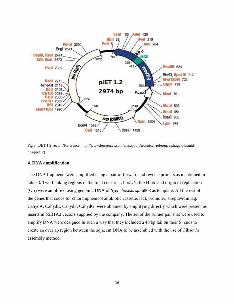
pJet vector
It is also commercially available vector with 2974 bp in length and is a high copy number
plasmid. The vector map in the figure 8 shows it consists of replicon pMB1 for replication of
plasmid, the bla(AmpR) gene coding for beta-lactamase and confers resistance to ampicillin
which helps in selection of recombinant Escherichia coli. The vector also consists of a modified
Eco47IR gene which includes a multiple cloning site and codes for Eco47I restriction
endonuclease which is lethal to all E. coli. strains and are not protected by cognate methylation.
So all the successful cloning at the multiple cloning sites causes insertion inactivation of
Eco47IR gene inhibiting the expression of lethal Eco47I restriction endonuclease. Because of
this only those cells which have recombinant plasmid will survive causing the positive selection.
It further consists of T7 and PlacUV5 promoters which are responsible for invitro transcription of
the inserted gene and expression of eco47IR gene respectively. It also consists of multiple
cloning site at position 328-422 where the cloning of desired insert at desired site can be
performed and is also used for mapping and screening purposes of the insert/product
(http://www.fermentas.com/en/support/technical-reference/phage-plasmid-dna/pjet12).
16
Fig 9. pJET 1.2 vector (Reference: http://www.fermentas.com/en/support/technical-reference/phage-plasmid-
dna/pjet12)
4. DNA amplification
The DNA fragments were amplified using a pair of forward and reverse primers as mentioned in
table 3. Two flanking regions in the final construct, hoxUY, hoxHfab and origin of replication
(Ori) were amplified using genomic DNA of Syenchosists sp. 6803 as template. All the rest of
the genes that codes for chloramphenicol antibiotic cassette, lacI, promoter, streptavidin tag,
CahydA, CahydE, CahydF, CahydG, were obtained by amplifying directly which were present as
inserts in pSB1A3 vectors supplied by the company. The set of the primer pair that were used to
fy DNA w r s g such w y h h y c u 40 h r 5’ s
cr v r r g w h j c DNA ss w h h us f G s ’s
assembly method.
17
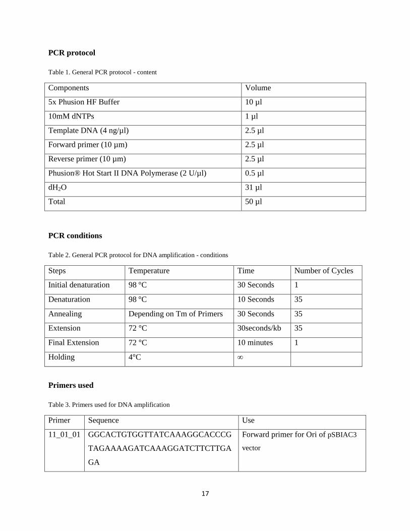
PCR protocol
Table 1. General PCR protocol - content
Components Volume
5x Phusion HF Buffer 10 µl
10mM dNTPs 1 µl
Template DNA (4 ng/µl) 2.5 µl
Forward primer (10 µm) 2.5 µl
Reverse primer (10 µm) 2.5 µl
Phusion® Hot Start II DNA Polymerase (2 U/µl) 0.5 µl
dH2O 31 µl
Total 50 µl
PCR conditions
Table 2. General PCR protocol for DNA amplification - conditions
Steps Temperature Time Number of Cycles
Initial denaturation 98 C 30 Seconds 1
Denaturation 98 C 10 Seconds 35
Annealing Depending on Tm of Primers 30 Seconds 35
Extension 72 C 30seconds/kb 35
Final Extension 72 C 10 minutes 1
Holding 4 C ∞
Primers used
Table 3. Primers used for DNA amplification
Primer Sequence Use
11_01_01 GGCACTGTGGTTATCAAAGGCACCCG
TAGAAAAGATCAAAGGATCTTCTTGA
GA
Forward primer for Ori of pSBIAC3
vector
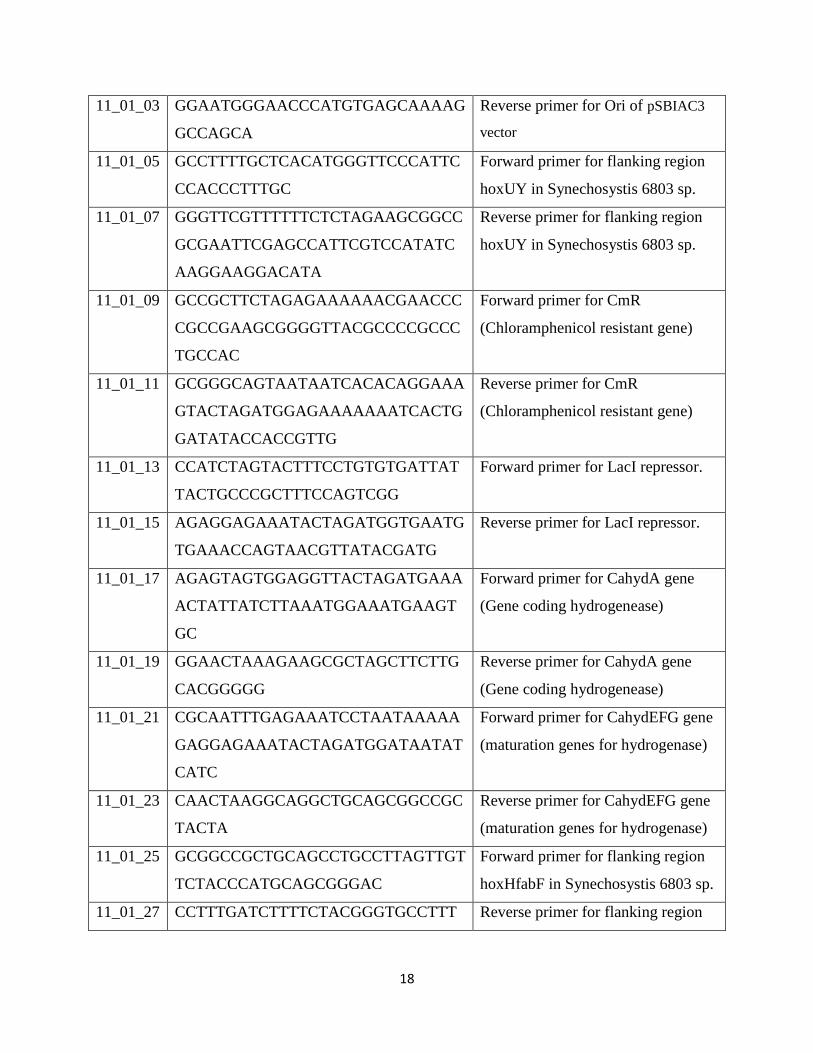
18
11_01_03 GGAATGGGAACCCATGTGAGCAAAAG
GCCAGCA
Reverse primer for Ori of pSBIAC3
vector
11_01_05 GCCTTTTGCTCACATGGGTTCCCATTC
CCACCCTTTGC
Forward primer for flanking region
hoxUY in Synechosystis 6803 sp.
11_01_07 GGGTTCGTTTTTTCTCTAGAAGCGGCC
GCGAATTCGAGCCATTCGTCCATATC
AAGGAAGGACATA
Reverse primer for flanking region
hoxUY in Synechosystis 6803 sp.
11_01_09 GCCGCTTCTAGAGAAAAAACGAACCC
CGCCGAAGCGGGGTTACGCCCCGCCC
TGCCAC
Forward primer for CmR
(Chloramphenicol resistant gene)
11_01_11 GCGGGCAGTAATAATCACACAGGAAA
GTACTAGATGGAGAAAAAAATCACTG
GATATACCACCGTTG
Reverse primer for CmR
(Chloramphenicol resistant gene)
11_01_13 CCATCTAGTACTTTCCTGTGTGATTAT
TACTGCCCGCTTTCCAGTCGG
Forward primer for LacI repressor.
11_01_15 AGAGGAGAAATACTAGATGGTGAATG
TGAAACCAGTAACGTTATACGATG
Reverse primer for LacI repressor.
11_01_17 AGAGTAGTGGAGGTTACTAGATGAAA
ACTATTATCTTAAATGGAAATGAAGT
GC
Forward primer for CahydA gene
(Gene coding hydrogenease)
11_01_19 GGAACTAAAGAAGCGCTAGCTTCTTG
CACGGGGG
Reverse primer for CahydA gene
(Gene coding hydrogenease)
11_01_21 CGCAATTTGAGAAATCCTAATAAAAA
GAGGAGAAATACTAGATGGATAATAT
CATC
Forward primer for CahydEFG gene
(maturation genes for hydrogenase)
11_01_23 CAACTAAGGCAGGCTGCAGCGGCCGC
TACTA
Reverse primer for CahydEFG gene
(maturation genes for hydrogenase)
11_01_25 GCGGCCGCTGCAGCCTGCCTTAGTTGT
TCTACCCATGCAGCGGGAC
Forward primer for flanking region
hoxHfabF in Synechosystis 6803 sp.
11_01_27 CCTTTGATCTTTTCTACGGGTGCCTTT Reverse primer for flanking region
19
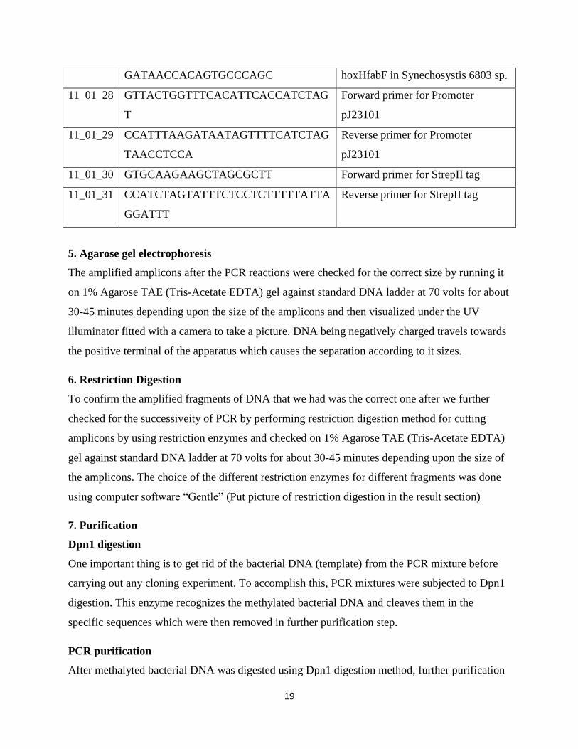
GATAACCACAGTGCCCAGC hoxHfabF in Synechosystis 6803 sp.
11_01_28 GTTACTGGTTTCACATTCACCATCTAG
T
Forward primer for Promoter
pJ23101
11_01_29 CCATTTAAGATAATAGTTTTCATCTAG
TAACCTCCA
Reverse primer for Promoter
pJ23101
11_01_30 GTGCAAGAAGCTAGCGCTT Forward primer for StrepII tag
11_01_31 CCATCTAGTATTTCTCCTCTTTTTATTA
GGATTT
Reverse primer for StrepII tag
5. Agarose gel electrophoresis
The amplified amplicons after the PCR reactions were checked for the correct size by running it
on 1% Agarose TAE (Tris-Acetate EDTA) gel against standard DNA ladder at 70 volts for about
30-45 minutes depending upon the size of the amplicons and then visualized under the UV
illuminator fitted with a camera to take a picture. DNA being negatively charged travels towards
the positive terminal of the apparatus which causes the separation according to it sizes.
6. Restriction Digestion
To confirm the amplified fragments of DNA that we had was the correct one after we further
checked for the successiveity of PCR by performing restriction digestion method for cutting
amplicons by using restriction enzymes and checked on 1% Agarose TAE (Tris-Acetate EDTA)
gel against standard DNA ladder at 70 volts for about 30-45 minutes depending upon the size of
the amplicons. The choice of the different restriction enzymes for different fragments was done
us g c u r s f w r “G ” (Put picture of restriction digestion in the result section)
7. Purification
Dpn1 digestion
One important thing is to get rid of the bacterial DNA (template) from the PCR mixture before
carrying out any cloning experiment. To accomplish this, PCR mixtures were subjected to Dpn1
digestion. This enzyme recognizes the methylated bacterial DNA and cleaves them in the
specific sequences which were then removed in further purification step.
PCR purification
After methalyted bacterial DNA was digested using Dpn1 digestion method, further purification

20
was employed using GeneJETTM
PCR purification Kit to get rid of all the proteins and other
unwanted chemicals in the PCR mixture and pure amplified DNA was extracted.
Gel Extraction
In some cases like in case of DNA that codes for Streptavidin TagII there were several unspecific
bands seen after checking it on 1% TAE agarose gel. In such conditions the gel was cut at their
respective position by visualizing it under blue box and purified using GeneJETTM
gel extraction
Kit. The elutes were obtained after the purification was performed and then taken forward for the
measurement of DNA concentration with the help of nanodrop using elution buffer as blank.
8. Constructs assembly
After amplifying all the required fragments the assembling of the DNA fragments together was
us g G s ’s ss y (1 s s h r DNA ss y h ). Th f c s ruc
was done in two installments ie. for assembling total of nine fragments together first we
assembled small number of fragments together ie. 2 or 3 in number to form a larger fragment and
then the final assembly was performed to make the final construct. For this to achieve the
equimolar (3 x 10⁻⁴
fragments) amount of each DNA fragments having overlap sequences were
put in a microfuge tube and then concentrated in the concentrator. Then 20 µl of Gibson master
mix was added to the concentrated DNA mixture and incubated at 50°C for 1 hour to favor the
assembly process. The product was finally checked in 1% TAE agarose gel to check the success
of the assembly reaction.
Gibson master mix components
Table 4. Gibson master mix components
Component Volume
5x Isothermal buffer 15 µl
T5 exonuclease (0.2 u/µl) 1.5 µl
Taq DNA ligase (40 u/µl) 7.5 µl
Phusion DNA polymerase (2u/µl) 1 µl
dH2O 75 µl
Total volume ( 5 Reactions) 100 µl
21
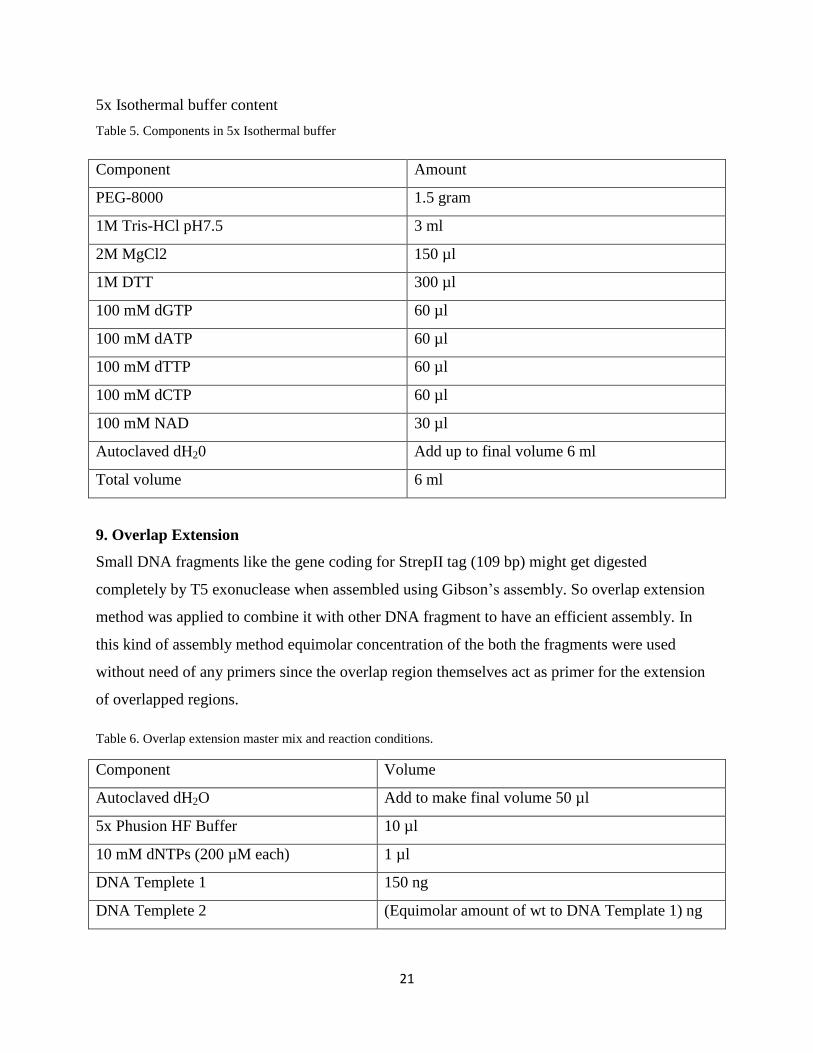
5x Isothermal buffer content
Table 5. Components in 5x Isothermal buffer
Component Amount
PEG-8000 1.5 gram
1M Tris-HCl pH7.5 3 ml
2M MgCl2 150 µl
1M DTT 300 µl
100 mM dGTP 60 µl
100 mM dATP 60 µl
100 mM dTTP 60 µl
100 mM dCTP 60 µl
100 mM NAD 30 µl
Autoclaved dH20 Add up to final volume 6 ml
Total volume 6 ml
9. Overlap Extension
Small DNA fragments like the gene coding for StrepII tag (109 bp) might get digested
completely by T5 exonuclease when assembled using Gibson’s ss y. So overlap extension
method was applied to combine it with other DNA fragment to have an efficient assembly. In
this kind of assembly method equimolar concentration of the both the fragments were used
without need of any primers since the overlap region themselves act as primer for the extension
of overlapped regions.
Table 6. Overlap extension master mix and reaction conditions.
Component Volume
Autoclaved dH2O Add to make final volume 50 µl
5x Phusion HF Buffer 10 µl
10 mM dNTPs (200 µM each) 1 µl
DNA Templete 1 150 ng
DNA Templete 2 (Equimolar amount of wt to DNA Template 1) ng
22
Phusion DNA Polymerase ( 0.02 u/µl) 0.5 µl
Total volume 50 µl
10. Preparation of competent cells
DH5α strains of E. coli were used for preparing competent cells. The DH5α strains were streaked
out and cultured in a test tube in 5 ml LB broth. They were then grown over-night at 37°C and
250 rpm shaker. Next day the 5ml of cultured DH5α strain was inoculated in a 2 liter sterile
conical flask containing 400 ml of LB medium. Then it was left to grow at 30°C at 125 rpm on a
shaker. The OD measurement was carried out at a regular interval of about 1 hour at 600nm of
light wavelength. When the OD measurement was found to be around 0.35 then the culture was
removed from the shaker and the provided standard protocol was followed for preparing the
competent cells.
Protocol for preparing competent cells
The culture was transferred into the pre-chilled sterile polypropylene tubes and left on ice for 5
to 10 minutes. The cells were then centrifuged for 7 minutes at 1600g (3000 rpm) at 4°C. The
supernatant was discarded and re-suspended in 10 ml ice-cold CCMB 80 buffer. Then the cells
were centrifuged at 5 minutes at 1100g (2500 rpm) at 4°C. The supernatant was discarded and
the pellets were re-suspended in 10 ml ice-cold CCMB 80 buffer. The re-suspended cells were
kept on ice for 30 minutes. Then the cells were centrifuged for 5 minutes again at 1100g at 4°C
and the supernatant was discarded. The cells were then re-suspended in 2 ml ice cold CCMB 80
buffer solution and the tubes were let on ice in the fridge for overnight. The next day the cells
were then transferred to pre-chilled sterile poly propylene tubes (250 µl aliquots) and were
frozen immediately at -80°C. The competency of the cells was checked by following standard
transformation protocol using Red Fluorescent Plasmid (RFP) and the transformation efficiency
was found to be 7.8 x 10⁶.
11. Transformation
The assembled constructs were transformed using DH5α competent cells which were prepared as
described above. The preserved competent cells were thawed on ice and approximately 5 ng of
the Gibson mixture was mixed with 100 µl of competent cells in a 1.5 ml eppendorf tube and
were suspended by mixing gently by pipetting up and down. Then the mixture was incubated on
23
ice for 30 minutes. Then heat shock was given for one minute at 42°C which plays an important
role for uptake of foreign DNA. Then the mixture was again incubated on ice for 5 minutes. 950
µl of fresh media was added to the transformation mixture and was incubated at 37 °C for 1 hour.
Finally the transformation mix was plated in 3 different plates with Chloramphenicol as
antibiotic used for selection taking 3 different volumes ( 1µl, 10µl, 100µl ). Then the plates were
incubated overnight at 37 °C.
12. Plasmid preparation
A single colony was picked from the streaked plate with the help of a pipette tip and was
inoculated in 5ml of LB containing Chloramphenicol as selection antibiotic in a 20 ml culture
tube. It was then incubated for 16 hours (overnight) at 37 °C while shaking at 250 rpm. Next
morning the cells were harvested by centrifuging the culture at 8000 rpm (6800 g) for 2 minutes
at room temperature. The supernatant was discarded and the pellet was further used for plasmid
preparation using Plasmid mini prep kit from Fermentas. The pellets were re-suspended in 250 µl
of resuspension solution containing RNase A and the bacteria were re-suspended completely by
vortexing and pipetting up and down. Then 250 µl of lysis solution was added and mixed
thoroughly. 350 µl neutralization solution was added and the cells were centrifuged at 12000 rpm
for 5 minutes to pellet down the unwanted cells debris and the chromosomal DNA. The clear
supernatant was pooled out by pipetting and added to the GeneJET spin column which was then
centrifuged for 1 minute. The flow through was discarded and the column was washed using 500
µl of wash solution (diluted with ethanol) by centrifuging for 1 minutes at 12000 rpm. The flow
through was discarded and then the plasmid DNA was eluted with 50 µl of provided elution
buffer.
13. Screening
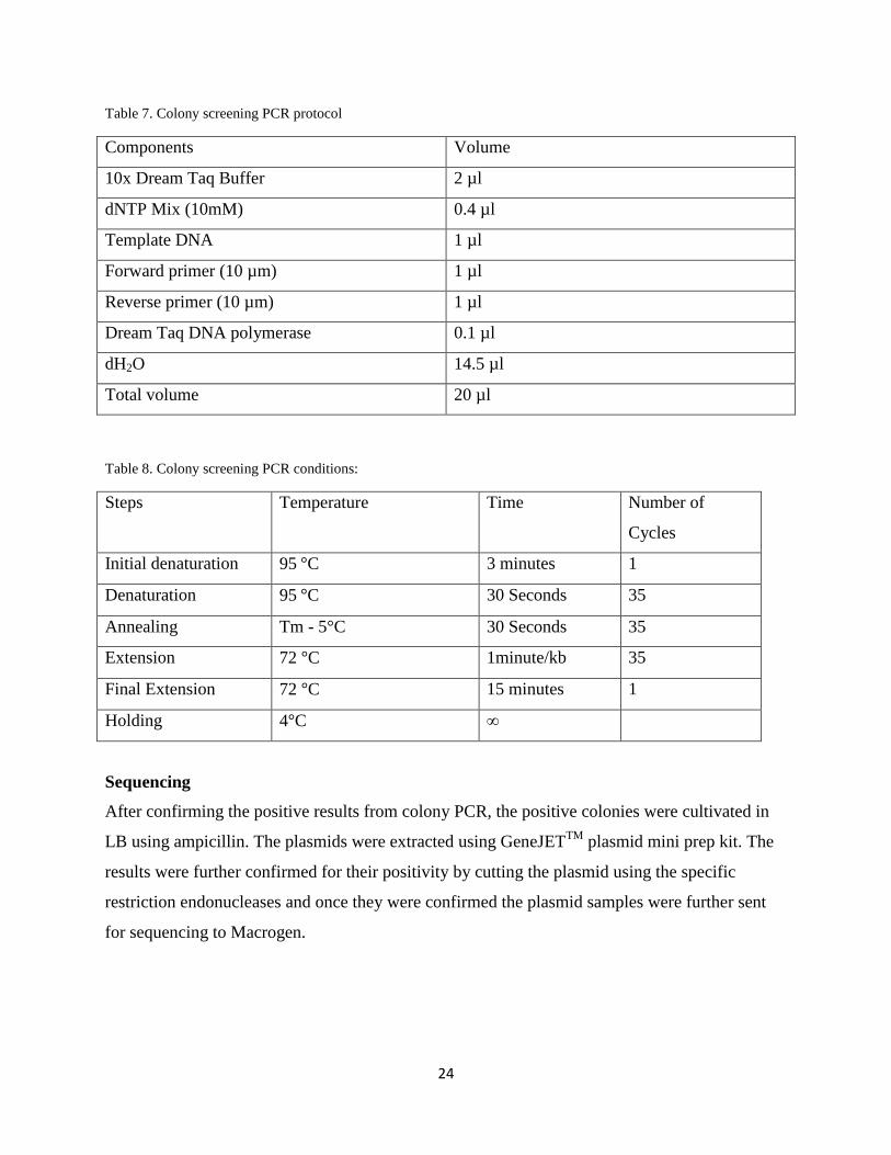
Colony screening PCR:
The selected positive colonies that were obtained after the transformation were applied for
colony screening PCR to check whether the results were positive. The PCR system consisted of
Dream Taq DNA Polymerase and its buffer which were obtained from Fermentas.
24
Table 7. Colony screening PCR protocol
Components Volume
10x Dream Taq Buffer 2 µl
dNTP Mix (10mM) 0.4 µl
Template DNA 1 µl
Forward primer (10 µm) 1 µl
Reverse primer (10 µm) 1 µl
Dream Taq DNA polymerase 0.1 µl
dH2O 14.5 µl
Total volume 20 µl
Table 8. Colony screening PCR conditions:
Steps Temperature Time Number of
Cycles
Initial denaturation 95 C 3 minutes 1
Denaturation 95 C 30 Seconds 35
Annealing Tm - 5°C 30 Seconds 35
Extension 72 C 1minute/kb 35
Final Extension 72 C 15 minutes 1
Holding 4 C ∞
Sequencing
After confirming the positive results from colony PCR, the positive colonies were cultivated in
LB using ampicillin. The plasmids were extracted using GeneJETTM
plasmid mini prep kit. The
results were further confirmed for their positivity by cutting the plasmid using the specific
restriction endonucleases and once they were confirmed the plasmid samples were further sent
for sequencing to Macrogen.
25
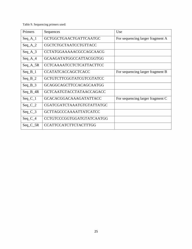
Table 9. Sequencing primers used:
Primers Sequences Use
Seq_A_1 GCTGGCTGAACTGATTCAATGC For sequencing larger fragment A
Seq_A_2 CGCTCTGCTAATCCTGTTACC
Seq_A_3 CCTATGGAAAAACGCCAGCAACG
Seq_A_4 GCAAGATATGGCCATTACGGTGG
Seq_A_5R CCTCAAAATCCTCTCATTACTTCC
Seq_B_1 CCATATCACCAGCTCACC For sequencing larger fragment B
Seq_B_2 GCTGTCTTCGGTATCGTCGTATCC
Seq_B_3 GCAGGCAGCTTCCACAGCAATGG
Seq_B_4R GCTCAATGTACCTATAACCAGACC
Seq_C_1 GCACACGGACAAAGATATTACC For sequencing larger fragment C
Seq_C_2 CGATCGATCTAAATGTGTATTATGC
Seq_C_3 GCTTAGCCCAAAATTATCATCC
Seq_C_4 CCTGTCCCGGTGGATGTATCAATGG
Seq_C_5R CCATTCCATCTTCTACTTTGG
26
Results
Gene isolation
All the nine fragments of DNA that constitutes the final constructs were amplified using the
primes with around 40 bp overlap to favor the 1 step isothermal DNA assembly method. Those
nine fragment with the name of their genes and their sizes are mentioned in the table: 10. The
amplicons were confirmed to be the correct ones by performing agarose gel electrophoresis in
1% TAE gel using standard 1 kb ladder to compare sizes.
Table 10. showing the genes, their sizes and templates
Fragment No. Size(bp) Name of the gene Template
1 709 ORI pSBIAC3
2 811 hoxUY Genomic DNA
3 732 CmR pSBIAC3
4 1134 LacI pSBIAC3
5 335 Promoter Direct Synthesis
6 1954 CahydA pSBIAC3
7 109 StrepII tag Direct Synthesis
8 3981 CahydEFG pSBIAC3
9 770 hoxHfabF Genomic DNA
Restriction Digestion
All the nine amplified fragments were then further checked for their accuracy by digesting them
using restriction endonucleases and then checking them in 1% TAE gel. The restriction digestion
enzymes used, the number of fragment produced and the size of fragments they formed after
digestion is shown in table: 11.
Table 11. showing the genes, restriction enzymes used, number of digested fragments and their sizes
Fragment
No.
Size(bp) Name of the gene Restriction
Enzymes
Fragment sizes Number of
Fragments
1 709 ORI
2 811 hoxUY ECORI 34 & 777 2
3 732 CmR StyI 180 & 552 2
4 1134 LacI BSSHII 343 & 991 2
5 335 Promoter VspI 102 & 233 2
6 1954 CahydA HindIII 664 & 1290 2
7 109 StrepII tag NheI 10 & 99 2
8 3981 CahydEFG StyI 138, 395, 751 & 2697 4
9 770 hoxHfabF ECORI 239 & 531 2
27
Overlap extension
Because of the small size of fragment no. 7 (106 bp) that codes for strepII tag, the direct
employment of G s ’s assembly method (one step isothermal recombination) might result in
complete degradation of this fragment by T5 exonuclease. So I employed overlap extension to
combine fragment no.6 and 7 together.
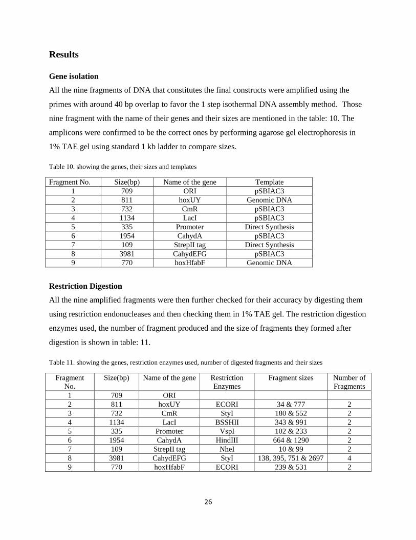
1 step isothermal recombination (Construction of larger fragments)
As per suggestion of the senior researchers and lab members working on the 1step isothermal
recombination method, I was suggested that the assembly method works best when the numbers
of fragments to be recombined are less and roughly of the same size. So I used maximum of
three different adjacent amplicons to combine them together and form larger fragments roughly
of the same size in first round of 1 step isothermal DNA assembly method. During the assembly
3 x 10⁻⁴
moles of each fragments mixed with Gibson master mix before 1hour of incubation at
50ºC. The assembled product were then amplified using a pair of forward and reverse primers
and checked in 1% TAE gel shown in figure: 10. The table: 12 shows the larger fragments
formed, their constituent small fragments and their final size after recombination.
Figure 10. Construction of larger fragments using 1 step isothermal recombination

28
Table 12. showing Gibson assembled product, their constituent genes and their sizes
Larger
fragments
Constituent Smaller fragments Final Size after
recombination
A hoxHfabF, Ori & hoxUY 2220
B CmR & LacI 1829
C Promotor, CahydA & StrepII
tag
2326
Cloning larger fragments into vectors
After combing the small DNA fragments together to form the larger fragments and confirming
them for their size they were further taken to be cloned into a vector. Firstly the fragments were
amplified to get larger amount of product and then they were purified by gel extraction method.
Fragments A and C were cloned into pJet vector whereas fragment B was cloned into
pBluescript all using blunt end cloning method. Fragment D which consists of genes HydEFG
was already present in pSB1C3 plasmid. After the ligation reaction, the DNA ligation mixture
was mixed with 100 µl of DH5α competent cells to favor transformation following the standard
protocol and was plated in LB plates with ampicillin as selection antibiotic. The plates were then
incubated overnight at 37 ºC.
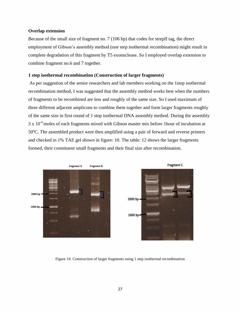
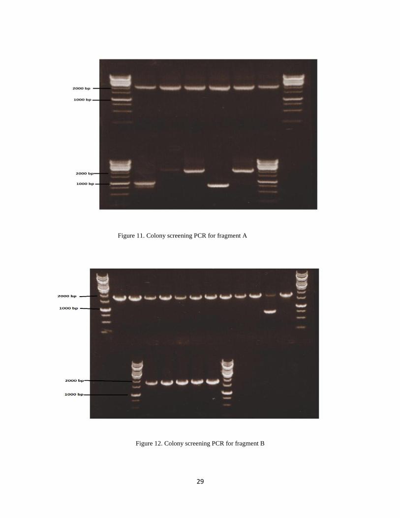
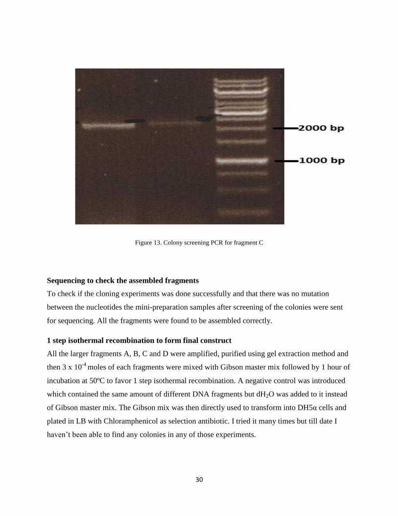
Colony screening PCR
After transformation a number of colonies were seen in the growth plates. The obtained positive
colonies were then taken forward for colony screening PCR. Out of total screening there were 8
positive colonies for fragment A, 16 for fragment B and 2 for fragment C shown in figure: 11, 12
and 13. The positive colonies were then cultured in LB and plasmid mini-preparation was carried
out to prepare the DNA samples and were send further for DNA sequencing.
29
Figure 11. Colony screening PCR for fragment A
Figure 12. Colony screening PCR for fragment B
30
Figure 13. Colony screening PCR for fragment C
Sequencing to check the assembled fragments
To check if the cloning experiments was done successfully and that there was no mutation
between the nucleotides the mini-preparation samples after screening of the colonies were sent
for sequencing. All the fragments were found to be assembled correctly.
1 step isothermal recombination to form final construct
All the larger fragments A, B, C and D were amplified, purified using gel extraction method and
then 3 x 10⁻⁴
moles of each fragments were mixed with Gibson master mix followed by 1 hour of
incubation at 50ºC to favor 1 step isothermal recombination. A negative control was introduced
which contained the same amount of different DNA fragments but dH2O was added to it instead
of Gibson master mix. The Gibson mix was then directly used to transform into DH5α cells and
plated in LB with Chloramphenicol as selection antibiotic. I tried it many times but till date I
h v ’ to find any colonies in any of those experiments.
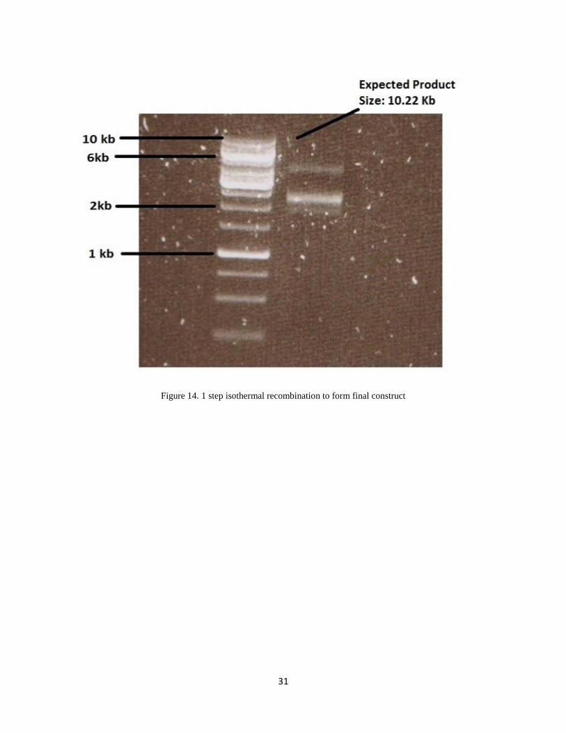
31
Figure 14. 1 step isothermal recombination to form final construct
32
Discussion
Starting with the amplification of all the small nine fragments as mentioned in table 10, the
amplicons of the correct size were amplified which were confirmed on the basis of their size by
checking the amplified product and also their restriction digestion product under 1% TAE gel.
Those fragments were taken further for 1 step isothermal DNA assembly to construct larger
fragments roughly of the same size which were named as A, B and C as mentioned on table: 12.
These fragments were finally achieved and were checked for their size by running under 1%
TAE gel as shown in figure 10, which finally were confirmed by sequencing. I tried several
times to make my final cons ruc us g G s ’s ss y (1 step isothermal DNA assembly)
method and transformed the product into competent cells and plated them in appropriate LB
medium with Chloramphenicol as selection antibiotic. But always there was something fishy
u h r su ’ ur u s x c . I v r f u y DNA band on the gel for
the expected final product of 10.22 Kb or colonies growing in the plates which opens up the
possibilities among one of the several reasons.
May be the DNA fragments have formed coils and secondary structure inhibiting the proper
assembly, may be the self-replication part or the antibiotic cassette ’ function leading no
growth.
G s ’s ss y h ( 1 s s h r DNA ss y) s c s r y w h
comparison to other ligation and cloning methods. It seems very straight forward, easy and saves
quite a lot of time. Keeping that in mind I have been using this method in my project to make my
construct. Till date I was able to combine the different pieces of DNA to form the larger
fragment of around 2.5 kb but I was not able to combine the fragments more that this size and
nor I was able to make a circular plasmid with this method. So it might be necessary to well
ch r c r z z h c s wh ch h G s ’s ss y h f v rs.
The construct was desined by a senior researcher Thorsten Heidorn who was working on the
same project before. There might be quite a lot of information missing that could have been
passed on to me with a face to face meeting. Some of the thing like the concept of the design,
their past learnings, what didnt work and what was his critical view about the project was just
limited to a bunch of the files that I was provided.
The construct which I am working on will be a circular plasmid as shown in figure: 6 will be
inserted heterologously into the Synechocystis sp. PCC 6803. But because I have not been able to
get the final construct till date I haven´t got the opportunity to check whether it works in the
foreign system. So still the prediction of the higher efficiency of hydrogen gas production by the
synthetic system is questionable.
33
Acknowledgements
I am grateful to my supervisor Prof. Peter Lindblad for providing me the opportunity to be a part
of cyano group and this project, feeding me with all those valuable knowledge and helping me
throughout all the challenges in this project.
I am also thankful to my laboratory supervisor Elias Englund for holding my hand in early days,
helping me with all the lab techniques and answering all of my queries. I extend my gratitude to
Helder Miranda, Rui Mao and Simmie Huyang for all the eye opening discussions we had
together. I cannot keep myself from thanking all the members of Cyano group for helping me to
adapt and come out of my shell by providing me a very nourishing, friendly and growing
environment.
34
References
Allakhverdiev, S. I., Kreslavski, V. D., Thavasi, V., Zharmukhamedov, S. K., Klimov, V. V.,
Nagata, T., Nishihara, H., et al. (2009). Hydrogen photoproduction by use of photosynthetic
organisms and biomimetic systems. Photochemical & photobiological sciences : Official
journal of the European Photochemistry Association and the European Society for
Photobiology, 8(2), 148–56. doi:10.1039/b814932a
Angermayr, S. A., Hellingwerf, K. J., Lindblad, P., & de Mattos, M. J. T. (2009). Energy
biotechnology with cyanobacteria. Current opinion in biotechnology, 20(3), 257–63.
doi:10.1016/j.copbio.2009.05.011
B r , P., D’A , S., B rg , E., V s , F., G c , G. M., & C s , P. (2011).
The cyanobacterium Synechocystis sp. PCC 6803 is able to express an active [FeFe]-
hydrogenase without additional maturation proteins. Biochemical and biophysical research
communications, 405(4), 678–83. doi:10.1016/j.bbrc.2011.01.095
Ducat, D. C., Sachdeva, G., & Silver, P. a. (2011). Rewiring hydrogenase-dependent redox
circuits in cyanobacteria. Proceedings of the National Academy of Sciences of the United
States of America, 108(10), 3941–6. doi:10.1073/pnas.1016026108
Gibson, D. G., Young, L., Chuang, R., Venter, J. C., Iii, C. A. H., Smith, H. O., & America, N.
(2009). Enzymatic assembly of DNA molecules up to several hundred kilobases, 6(5), 12–
16. doi:10.1038/NMETH.1318
Horch, M., Lauterbach, L., Lenz, O., Hildebrandt, P., & Zebger, I. (2012). NAD(H)-coupled
hydrogen cycling - structure-function relationships of bidirectional [NiFe] hydrogenases.
FEBS letters, 586(5), 545–56. doi:10.1016/j.febslet.2011.10.010
Ludwig, M., Cracknell, J. a, Vincent, K. a, Armstrong, F. a, & Lenz, O. (2009). Oxygen-tolerant
H2 oxidation by membrane-bound [NiFe] hydrogenases of ralstonia species. Coping with
low level H2 in air. The Journal of biological chemistry, 284(1), 465–77.
doi:10.1074/jbc.M803676200
Melis, A., & Happe, T. (2001). Update on Hydrogen Production Hydrogen Production . Green
Algae as a Source of Energy 1, 127(November), 740–748. doi:10.1104/pp.010498.740
Parmar, A., Singh, N. K., Pandey, A., Gnansounou, E., & Madamwar, D. (2011). Cyanobacteria
and microalgae: a positive prospect for biofuels. Bioresource technology, 102(22), 10163–
72. doi:10.1016/j.biortech.2011.08.030
Risser, D. D., Wong, F. C. Y., & Meeks, J. C. (2012). Biased inheritance of the protein PatN
frees vegetative cells to initiate patterned heterocyst differentiation. Proceedings of the
National Academy of Sciences of the United States of America, 109(38), 15342–7.
doi:10.1073/pnas.1207530109
35
Sarma, S. J., Brar, S. K., Le Bihan, Y., & Buelna, G. (2012). Bio-hydrogen production by
biodiesel-derived crude glycerol bioconversion: a techno-economic evaluation. Bioprocess
and biosystems engineering. doi:10.1007/s00449-012-0755-8
Schwab, D. E., Tard, C., Brecht, E., Peters, J. W., Pickett, C. J., & Szilagyi, R. K. (2006). On the
electronic structure of the hydrogenase H-cluster. Chemical communications (Cambridge,
England), (35), 3696–8. doi:10.1039/b604994j
Biofuels. Accessed: September 18, 2012. [online]
http://www.alternative-energy-news.info/technology/biofuels/
Biofuel. Accessed: September 18, 2012. [online]
http://biofuel.org.uk/
Thermo scientific. Accessed: September 20, 2012. [online]
http://www.fermentas.com/en/support/technical-reference/phage-plasmid-dna/pbluescriptII
Thermo scientific. Accessed: September 20, 2012. [online]
http://www.fermentas.com/en/support/technical-reference/phage-plasmid-dna/pjet12
The microbial cell project on the cyanobacterium Synechocystis sp. PCC 6803. Accessed:
September 20, 2012. [online]
http://synechocystis.asu.edu/\z