design, installation, inspection, testing, operation and ... · suruhanjaya tenaga (energy...
TRANSCRIPT

Guideline for theDesign, Installation, Inspection, Testing,
Operation and Maintenance of Water
Heater Systems
GP/ST/No.6/2016

Guideline for the Design, Installation, Inspection, Testing, Operation and Maintenance of Water Heater Systems
GP/ST/No.6/20161
Guideline for theDesign, Installation, Inspection, Testing,
Operation and Maintenance of Water
Heater Systems

2Guideline for the Design, Installation, Inspection, Testing, Operation and Maintenance of Water Heater Systems
GP/ST/No.6/20162
© All rights reserved. Reproduction of all or any part of this publication via electronic, mechanical, recording or other medium is strictly prohibited without written consent from the Energy Commission.
Published by:SURUHANJAYA TENAGA (ENERGY COMMISSION)No. 12, Jalan Tun Hussein, Precinct 2, 62100 Putrajaya, MalaysiaT: (603) 8870 8500F: (603) 8888 86371-800-2222-78 (ST)www.st.gov.my
ISBN : 978-967-13778-7-1ST Publication Number : ST(P) 21/11/2016
PRINTED IN MALAYSIA

Guideline for the Design, Installation, Inspection, Testing, Operation and Maintenance of Water Heater Systems
GP/ST/No.6/20163
ELECTRICITY SUPPLY ACT 1990[Act 447]
GUIDELINE FOR THE DESIGN, INSTALLATION, INSPECTION, TESTING, OPERATION AND MAINTENANCE OF WATER HEATER SYSTEMS
GP/ST/No.6/2016
IN exercise of power conferred by Section 50c of the Electricity Supply Act 1990 [Act 447], the commission issues the following guideline:
Citation and Commencement
1. This Guideline may be cited as the “Guideline for The Design, Installation, Inspection, Testing, Operation and Maintenance of Water Heater Systems”.
2. This Guideline shall come into operation on the date of registration.
Interpretation
3. In this Guideline, unless the context otherwise requires –
Act mean the Electricity Supply Act 1990 [Act 447], Electricity Supply (Amendment) Act 2015 [Act A1501] and its subsequent amendment, if any.
Purpose of this Guideline
4. The purpose of this Guideline is to guide industry and the public on the design, installation, inspection, testing, operation and maintenance of water heater systems usually used in residential and commercial buildings, hotels, resorts, etc. It shall be applicable to instantaneous, storage and solar water heaters. Storage and solar water heater capacities of up to 300 liters are covered by this Guideline.
4Guideline for the Design, Installation, Inspection, Testing, Operation and Maintenance of Water Heater Systems
GP/ST/No.6/20164
Application of this Guideline
5. This Guideline will address:i. safety aspects of electrical wiring and accessories in the design, installation,
inspection, testing, operation and maintenance of water heater systems; and the safety and efficiency aspects in the operation and use of water heater systems.
Notice by the Commission
6. The Commission may issue written notices from time to time in relation to this Guideline.
Amendment and Variation.
7. The Commission may at any time amend, modify, vary or revoke this Guideline.
Dated: 7 April 2017
DATUK IR. AHMAD FAUZI BIN HASANChief Executive Officerfor Energy Commission

Guideline for the Design, Installation, Inspection, Testing, Operation and Maintenance of Water Heater Systems
GP/ST/No.6/20165
CONTENT06 Foreword
07 Chapter 1: Scope
08 Chapter 2: Normative References
09 Chapter 3: Terms and Definitions
10 Chapter 4: Installation of Water Heater
23 Chapter 5: Operation and Maintenance of Water Heater
26 Annex A: Cases of Electrical Accidents involving Electric Water Heater
32 Annex B: Illustration of earthing arrangements, protective conductors and protective bonding conductors
34 Acknowledgements
36 List of Energy Commission Main and Regional Offices

6Guideline for the Design, Installation, Inspection, Testing, Operation and Maintenance of Water Heater Systems
GP/ST/No.6/20166
Foreword
This Guideline was developed by the Work Group on Water Heater Systems under the authority of the Energy Commission of Malaysia.
A number of fatal accidents involving water heater have occurred in the country. The causes of these accidents have been identified as being both electrical and non electrical in nature. As such, the Energy Commission had taken the initiative to address this issue by producing this Guideline on the design, installation, inspection, testing, operation and maintenance of water heater systems with the view of ensuring the safe use of electric water heater.
It was developed for the use of: -
i. manufacturers, importers and retailers of electric and solar water heater systems with the view of them incorporating the necessary safety features in their products;
ii. installers of electrical and solar water heater systems;iii. those involved in the maintenance of electrical and solar water heater systems; andiv. the general public and users of electrical and solar water heater systems.
This Guideline will be subjected to periodic review to reflect current needs and technological advancements. Users and other interested parties may submit comments on the contents of this Guideline for consideration in future versions.
Compliance with a Malaysian Guideline does not itself confer immunity from legal obligations.

Guideline for the Design, Installation, Inspection, Testing, Operation and Maintenance of Water Heater Systems
GP/ST/No.6/20167
CHAPTER 1: SCOPE
This Guideline gives guidance on the good design, installation, inspection, testing, operation and maintenance of water heater systems usually used in residential installations, commercial building, hotel, resort and etc. It shall include instantaneous, storage and solar water heaters. Both storage and solar water heaters included in this Guideline is for capacities of up to 300 liters. It will address: -
i. The installation of the water heater in the aspect of the electrical wiring and accessories to ensure safe operation and use of the water heater; and
ii. Safe, efficient operation and use of the water heater.
This Guideline does not include the safety requirements of the water heater itself, as they are covered by other Malaysian Standards, including the following: -
i. MS IEC 60335-1:2013: Household and similar electrical appliances - Safety - Part 1: General requirements;
iii. MS 1597-2-35:2010 (IEC 60335-2-35:2006, mod): Household and similar electrical appliances - Safety - Part 2-35: Particular requirements for instantaneous water heater (second revision); and
iii. MS 1597-2-21:2015 (IEC 60335-2-21:2012, mod): Household and similar electrical appliances - Safety - Part 2-21: Particular requirements for storage water heater (second revision).

8Guideline for the Design, Installation, Inspection, Testing, Operation and Maintenance of Water Heater Systems
GP/ST/No.6/20168
CHAPTER 2: NORMATIVE REFERENCES
MS IEC 60335-1:2013: Household and similar electrical appliances - Safety - Part 1: General requirements
MS 1597-2-35:2010 (IEC 60335-2-35:2006, mod): Household and similar electrical appliances - Safety - Part 2-35: Particular requirements for instantaneous water heater (second revision)
MS 1597-2-21: 2015 (IEC 60335-2-21: 2012, mod): Household and similar electrical appliances - Safety - Part 2-21: Particular requirements for storage water heater (second revision)
MS IEC 60364 : Electrical Installations of Buildings
MS 1936: 2016 : Electrical Installations of Buildings – Guide to MS IEC 60364
MS 1979: 2015 : Electrical Installations of Buildings – Code of Practice
BS 7671:2015 : Requirements for Electrical Installations
Guideline for the Design, Installation, Inspection, Testing, Operation and Maintenance of Water Heater Systems
GP/ST/No.6/20169
CHAPTER 3: TERMS AND DEFINITIONS
3.1 Normal Operation Operation of the appliance while supplied with water, the flow being adjusted to attain
the highest outlet water temperature without operation of the thermal cut-out.
3.2 Instantaneous Water Heater Stationary appliance for heating water while it flows through the appliance. Note: instantaneous water heater are referred to as water heater.
3.3 Closed Water Heater Instantaneous water heater intended to operate at the pressure of the water system, the
flow of water being controlled by one or more valves in the outlet system. Note: the operating pressure may be the output pressure of a reducing or boosting
device.
3.4 Open-outlet Water Heater Instantaneous water heater in which the flow of water is controlled by a valve in the inlet
pipe, there being no valve in the outlet pipe.
3.5 Bare-element Water Heater Instantaneous water heater in which uninsulated heating elements are immersed in the
water.
3.6 Rated Pressure Water pressure assigned to the appliance by the manufacturer.
3.7 Flow Switch Switch that operates in response to a flow of water.
3.8 Pressure Switch Switch that operates in response to a change in pressure.
3.9 Solar Water Heater Complete assembly of subsystems and components necessary to convert solar energy
into thermal energy for the heating of water and may include an auxiliary heat source (ISO 9459-2:1995).
(water heater which includes a collector and storage tank, and uses the sun’s thermal energy to heat water).
3.10 Storage Water Heater An appliance intended for heating water in a thermally well insulated container, for
long-term storage of the heated water, and provided with a device to control the water temperature.
3.11 Water Heater Systems Complete system consists of heat generation, heat storage, electrical connections from
mains, plumbing connections, and mechanical fittings.
10Guideline for the Design, Installation, Inspection, Testing, Operation and Maintenance of Water Heater Systems
GP/ST/No.6/201610
CHAPTER 4: INSTALLATION OF WATER HEATER
4.1 Electrical installation
4.1.1 Regulatory requirements and standards compliance
a) All electrical installations and equipment shall comply with Electricity Supply Act 1990 [Act 447] and Electricity Regulations 1994.
b) All electrical installations and equipment, in addition to compliance with relevant product standards, shall comply with the following standards:
i. Non–residential or similar installation– MS 1936:2016 Electrical installations of buildings – Guide to MS IEC 60364;
ii. Residential or similar installation– MS 1979: 2015 Electrical installations of buildings – Code of practice;
iii. IEC 60364–7–701:2006 Low voltage electrical installations – Part 7–701: Requirements for special installation or locations – Locations containing a bath or shower; and
iv. MS IEC 60364: Electrical installations of buildings and MS IEC 60038:2008 IEC Standard voltages.
a. Nominal voltage: Single or Three Phase: 230/400V -6%, +10%, 50 Hz + 1; andb. Earthing system: TT.
c) All electrical installations works shall be carried out by electrical contractor registered with Energy Commission or wireman in compliance with Electricity Supply Act 1990 [Act 447] and Electricity Regulations 1994.
i. The wireman shall have valid certificates and registered with the Energy Commission; and
ii. The electrical contractor shall have valid certificate of registration with the Energy Commission.
d) The installation equipment shall comply with relevant product standards as per Table 1.
i. If no MS or MS IEC standard exists, the relevant IEC standard shall apply;
ii. The competent person as described at clause 4.1.1.c, shall ensure safety by carrying out a risk management study to ensure that the risk of use is within the accepted level; and
iii. All equipment shall be approved by the Energy Commission if required.

Guideline for the Design, Installation, Inspection, Testing, Operation and Maintenance of Water Heater Systems
GP/ST/No.6/201611
EQUIPMENT STANDARD
Consumer Unit IEC 61439–3:2012
Final distribution board IEC 61439–3:2012
*Miniature Circuit Breaker (MCB) MS IEC 60898–1:2007 (confirmed 2011)MS IEC 60898–2:2007 (confirmed 2011)
Circuit breaker MS IEC 60947–2:2010
*Residual current device (RCD)
MS IEC 61008–1:2012MS IEC 61008–2:2003 (confirmed 2011)MS IEC 61009–1:2012MS IEC 61009–2:2003 (confirmed 2011)
Wire and cable for fixed wiring450/750V PVC insulated cable (non-sheathed)600/1000V PVC insulated cable (non-armoured)
MS 2112–3:2009/ MS 2112–4:2009MS 2100:2007/ MS 2101:2007/ MS 2102:2007/ MS 2103:2007
Cable trunking and ducting conduit MS 1777:2006MS IEC 61386:2010
Double pole switch (Up to 63A) **MS IEC 60669:2012 (Non – Electronic)
Flexible wire and cable MS 2112–5:2009
Connector
MS IEC 60998-1:2005 (confirmed 2015)MS IEC 60998-2-2:2005 (confirmed 2015)MS IEC 60998-2-3:2005 (confirmed 2015)MS IEC 60998-2-4:2005 (confirmed 2015)MS1873:2005MS1873-22:2006IEC 60670-22:2003+AMD1:2015
Connection unit (joint box), junction box, terminal blocks, cable lug
MS 1540:2015MS1838:2015MS1873:2005BS 1363-4:1995+A4:2012
*MCB – RCD combinations such as RCBO are acceptable as replacement** Electronic switches are not permitted by MS IEC 60364
Table 1: Electrical Standard for Installation Equipment

12Guideline for the Design, Installation, Inspection, Testing, Operation and Maintenance of Water Heater Systems
GP/ST/No.6/201612
Conductor Colour Code
Live Red
Neutral Black
Protective Earthing Green
Equipotential bonding Green
Conductor Colour Code
Live – Red phase Red
Live – Yellow phase Yellow
Live – Blue phase Blue
Neutral Black
Protective Earthing Green
Equipotential bonding Green
Conductor Colour Code
Live – Red / Yellow / Blue Red / Yellow / Blue
Neutral Black
Protective Earthing Green
Equipotential bonding Green
4.1.2 Wire or Cable Colour Code for Electrical Installations
a) Single phase supply: The colour code shall comply with Table 2.
b) Three phase supply single phase circuit: The colour code shall comply with Table 3.
c) Three phase supply three phase circuit: The colour code shall comply with Table 4.
Table 2: Single phase supply: Wire or cable colour code.
Table 3: Three phase supply single phase circuit: Wire or cable colour code.
Table 4: Three phase supply three phase circuit: Wire or cable colour code.
Guideline for the Design, Installation, Inspection, Testing, Operation and Maintenance of Water Heater Systems
GP/ST/No.6/201613
4.1.3 Voltage drop
a) The maximum voltage drop from the point of coupling with the electricity provider (i.e. distribution board or consumer unit) and the disconnector connecting to the water heater systems shall be less than or equal to 5%.
b) The recommended maximum length of final circuit of water heater system is equal to or less than 50 meter from the distribution board (DB) or consumer unit.
i. The voltage drop shall be checked if the circuit length is longer than 50 meter. In this case, a bigger size conductor shall be used to get the voltage drop below 5%.
4.1.4 Requirements of Final Circuits Supplying the Water Heater Systems
a) The final circuit supplying the water heater systems shall originate only from final distribution board (DB) or consumer unit as shown in Figure 1 to Figure 4.
i. The incoming of final distribution board or consumer unit shall incorporate a series MCB - RCD protection scheme. The sensitivity of the RCD shall be equal to or less than 100 mA for protection against thermal effects; and
ii. The MCB and RCD provide over–current and electric shock protection respectively.
b) The outgoing final circuit supplying the water heater systems shall be a dedicated outgoing circuit supplying the water heater systems only and shall not be used and/or shared for other purpose.
i. Power and lighting circuits shall not share a conduit/trunking;
ii. Only rigid conduit/trunking shall be used as cable management system;
iii. The space factor of conduit shall not be more than 40%. The space factor of trunking shall not be more than 45%; and
iv. The final circuit for water heater systems shall be preferably fixed wiring.
c) The dedicated final circuit of water heater systems shall be protected by a series MCB – RCD protection scheme.
i. The sensitivity of the RCD shall be equal to or less than 10 mA.ii. The disconnection scheme of the MCB, RCD, Isolator / Disconnector,
switches and Protective Earthing (PE) shall be as per Table 5.

14Guideline for the Design, Installation, Inspection, Testing, Operation and Maintenance of Water Heater Systems
GP/ST/No.6/201614
Figure 1: Example of schematic diagram for single-phase water heater.
L N
230V 1P 50HZ EARTHING
2P SWITCHED MAINTENANCE
DISCONNECTORWITH INDICATOR
L
PE
PE
N
FIN
AL
CIR
CU
IT
DISTRIBUTIONBOARD
10mARCD 2P
1PMCB
METAL CLAD CONSUMERUNIT/DB ONLY
SUB-MAIN/DISTRIBUTIONCIRCUIT
2P CIRCUIT BREAKER /ISOLATOR
100mARCD 2P
WATERHEATER

Guideline for the Design, Installation, Inspection, Testing, Operation and Maintenance of Water Heater Systems
GP/ST/No.6/201615
Figure 2: Example of schematic diagram for three-phase water heater.Note: Supplementary Equipotential Bonding (SEB) shall be installed for additional protection
as per Clause 701.415.2 of IEC 60364-7-701:2006, Clause 544.2 of MS IEC 60364-5-54:2004 and Annex B of MS IEC 60364-5-54:2004.
L1 L2 L3 N
FIN
AL
CIR
CU
IT
DISTRIBUTIONBOARD
400V 3P 50HZ
L1L2L3
N
4P CIRCUITBREAKER /ISOLATOR
100mARCD 4P
WATERHEATER
4P MAINTENANCEISOLATOR /
DISCONNECTORWITH INDICATOR
EARTHING
PE
PE
METAL CLAD CONSUMERUNIT/DB ONLY
10mARCD 4P
3PMCB
3P 3P

16Guideline for the Design, Installation, Inspection, Testing, Operation and Maintenance of Water Heater Systems
GP/ST/No.6/201616
d) The MCB and RCD ratings and cross–sectional area of the conductors shall be as per Table 6.
i. Only electrical current capacity graded copper conductor cables and equipment are permitted to be used in current carrying applications for installations.
e) Water heater installed in zone 1 shall have an IP rating of at least IPX5. All installations and equipment shall be located outside zone 2 as per IEC 60364–7–701:2006.
Figure 3: The installation of RCD for instantaneous water heater with leakage current sensitivity of 10mA in a wet area.
Figure 4: The installation of RCD for storage water heater with leakage current sensitivity of 10mA in a wet area.

Guideline for the Design, Installation, Inspection, Testing, Operation and Maintenance of Water Heater Systems
GP/ST/No.6/201617
Type of Circuit MCB RCD Isolator / Disconnector Switches PE
Single phase 1 pole 2 pole 2 pole 1 pole No Break Permitted
Three phase 3 pole 4 pole 4 pole 3 pole No Break Permitted
Water Heater Rating @ 230V LoadMCB/RCD
(Minimum)Live Neutral PE
<2,856W 12.4A 16A 4 mm2 4 mm2 4 mm2
>2,856W to < 3,570W 15.5A 20A 4 mm2 4 mm2 4 mm2
>3,570W to < 4,462W 19.4A 25A 4 mm2 4 mm2 4 mm2
>4,462W to < 5,711W 24.8A 32A 4 mm2 4 mm2 4 mm2
>5,711W to < 7,139W 31A 40A 6 mm2 6 mm2 6 mm2
>7,139W to < 8,924W 38.8A 50A 10 mm2 10 mm2 10 mm2
For ratings of more than the above table, the cable shall be sized as per MS IEC 60364
d) The MCB and RCD ratings and cross–sectional area of the conductors shall be as per Table 6.
i. Only electrical current capacity graded copper conductor cables and equipment are permitted to be used in current carrying applications for installations.
e) Water heater installed in zone 1 shall have an IP rating of at least IPX5. All installations and equipment shall be located outside zone 2 as per IEC 60364–7–701:2006.
Table 5: Disconnection scheme of MCB, RCD, Isolator / Disconnector, Switches and PE.
Table 6: Minimum conductor sizes.

18Guideline for the Design, Installation, Inspection, Testing, Operation and Maintenance of Water Heater Systems
GP/ST/No.6/201618
Figure 8: Wrong Electrical Connection
WATERHEATER
Zone 1*
Zone 1
Zone 1
Zone 0
Zone 2 Zone 3
Zone 0
Zone 2 Zone 3
2.40 m0.60 m
Zone 1*
Zone 0
Zone 2 Zone 3
2.40 m
0.60 m
2.25 m
2.40 m
(*) Zone 1 is above the bath as shown in the vertical cross-section
0.60 m
TOP VIEW
SIDE VIEW
i. Only fixed and permanent connection is allowed, 13A/15A plug and socket shall not be used as shown in Figure 5. If there is a connection in between, only approved connector and connection box shall be used. For connection within the shower cubicle and below the ceiling, the connection box shall be IPX5 rated;
ii. The classifications of zones are as illustrated in Figures 6-9; andiii. Any equipment outside zone 1 subject to water spraying hazard shall
have an IP rating of at least IPX5.
Figure 5: Wrong Electrical Connection
Figure 6: Zones 0, 1, 2 and 3 in proximity to a bath tub. (*) Zone 1 is above the bath as shown in the vertical cross-section

Guideline for the Design, Installation, Inspection, Testing, Operation and Maintenance of Water Heater Systems
GP/ST/No.6/201619
Zone 1Zone 0
Zone 1
Zone 1
Zone 0
Zone 3Zone 2
Zone 2
0.60 m
0.60 m
2.40 m
2.40 m
2.25 m
Zone 3 Zone 0Zone 1
Zone 2
0.60 m
2.40 m
Zone 3
TOP VIEW
SIDE VIEW
Figure 7: Zones 0, 1, 2 and 3 in proximity of a shower with basin.
(1) When the shower head is at the end of a flexible tube, the vertical central axis of a zone passes through the fixed end of the flexible tube
Zone 1
Zone 1
(1) When the shower head is at the end of a flexible tube, the vertical central axis ofa zone passes through the fixed end of the flexoble tube
Zone2
Zone 3
Zone 2
Zone 3
0.60 m
0.60 m
Fixed showerhead (1)
2.40 m
Zone 1
Zone 2
Zone 3
0.60 m
0.60 m
Fixed showerhead (1)
2.40 m
2.25 m
Zone 1
Zone 1
(1) When the shower head is at the end of a flexible tube, the vertical central axis ofa zone passes through the fixed end of the flexoble tube
Zone2
Zone 3
Zone 2
Zone 3
0.60 m
0.60 m
Fixed showerhead (1)
2.40 m
Zone 1
Zone 2
Zone 3
0.60 m
0.60 m
Fixed showerhead (1)
2.40 m
2.25 m
TOP VIEW
SIDE VIEW
Figure 8: Zones 0, 1, 2 and 3 in proximity of a shower without basin.

20Guideline for the Design, Installation, Inspection, Testing, Operation and Maintenance of Water Heater Systems
GP/ST/No.6/201620
Prefabricatedshowercabinet
0.60 m
0.60 m
TOP VIEW
f) The water heater system circuit shall be terminated in a 2 or 4 pole switched maintenance disconnector with indicator.
i. This 2 or 4 pole switched maintenance disconnector shall be three (3) meters radius from the water heater system; and
ii. Alternatively, a 2 or 4 pole control switch with indicator and isolator combination can be used.
4.1.5 Connecting to the water heater system
a) In the case where a direct connection cannot be made to the water heater, an approved, correctly sized (MS IEC 60335-1: 2013) copper flexible cable with maximum 1.5 meter length, shall be used to connect the water heater to the connection box.
4.1.6 Earthing
a) The integrity of earthing is the most important factor in ensuring the reliable operation of the protective devices, especially the RCD for protection of safety against electric shock hazard.
b) An earth loop impedance tester shall be used to test the earthing impedance of the completed installation and the installation earth loop impedance earth.
4.1.7 Isolation Barrier
a) Storage water heater, solar thermal water heater, and multipoint instantaneous water heater shall be prefitted with isolation barriers at both water inlet and outlet connections. The specifications of the isolation barrier shall comply with the latest relevant requirements of MS 1597-2-21:2015.
b) The isolation barriers shall be installed at immediate connection to the water heater, as per Figure 10 below.
Figure 9: No switch is permitted within 60 cm of the door opening of a shower cabinet.

Guideline for the Design, Installation, Inspection, Testing, Operation and Maintenance of Water Heater Systems
GP/ST/No.6/201621
4.2 Hose Material and Minimum Length
4.2.1 The flexible hose from the water heater to the shower head shall not be of metallic or chrome based material. It shall not be conductive. The minimum length of the hose shall be 1 meter, for hoses of internal diameter 10 mm to ensure an insulation resistance of at least 1 Mega-ohm at maximum operating temperature.
4.3 Proper Location of Equipment
4.3.1 Water heater and storage tank shall be located and connected so as to provide access for observation, maintenance, servicing and replacement. The working space needed for this purpose shall provide reasonably access, i.e. 76 cm x 76 cm (30 inches x 30 inches).
If the storage water heater is to be installed above the ceiling, a reasonably access i.e. 60 cm x 60 cm (24 inches x 24 inches) shall be provided, at the close vicinity of the water inlet, outlet and electrical connection.
4.3.2 The water heater shall be located such that other fixed appliances installed in the room are located out of reach by a person using the bath or shower.
Figure 10: Installation of Isolation Barriers.
Pressure Relief Valve
Cold Water Inlet
Isolation barrier
Hot Water Outlet
22Guideline for the Design, Installation, Inspection, Testing, Operation and Maintenance of Water Heater Systems
GP/ST/No.6/201622
4.4 Need for Pressure Relief Valves (PRV), Drain Valves, Temperature Limiting Devices and Dry Burn Protection
4.4.1 To reduce the risk of abnormally high and dangerous pressures in the hot water system and to reduce chances of a dangerous explosion, the water heater shall be incorporated with PRV, drain valves and temperature limiting devices as required by MS 1597-2-35:2010 or MS 1597-2-21:2015 as applicable.
4.4.2 The discharge of PRV shall be connected to the drain and shall be ensured of no possibility to be blocked (no isolation valve shall be fitted). The water heater shall be protected against dry burn.
4.4.3 The PRV is recommended to be replaced with a new valve every five (5) years.
4.5 Inspection and Testing
4.5.1 The following shall be inspected and tested after installation: -
a) Inspect: visible mechanical damages or blockages;
b) Inspect: incorrect installation;
c) Inspect: loose termination;
d) Test earth loop impedance;
e) Functional Test: operation of the RCD; and
f ) Mechanical Test: operation of MCB.
4.6 Insulation of Water Heater and Pipes
4.6.1 Insulation blanket for storage water heater and insulation wrap for the hot water pipes can reduce energy costs. It must be ensured that the insulation is placed adequately and properly maintained.
4.7 Mounting of Water Heater
4.7.1 For wall mounted storage water heater, only expansion bolts provided or recommended by the manufacturer shall be used. For solar water heater, the structure where the heater tank is seated shall withstand at least twice the weight of the fully filled tank. The orientation of water heater shall be in accordance with the installation instructions provided by the manufacturer.

Guideline for the Design, Installation, Inspection, Testing, Operation and Maintenance of Water Heater Systems
GP/ST/No.6/201623
CHAPTER 5: OPERATION AND MAINTENANCE OF WATER HEATER
5.1 Periodic Maintenance
5.1.1 It is recommended that periodic maintenance shall be carried out at least once every six (6) months.
5.1.2 The water heater systems shall be switched off using the maintenance disconnector prior to maintenance.
5.1.3 Periodic maintenance shall be carried out on the following aspects: -
a) Inspect the disconnector for signs of over-temperature;
b) Inspect the parts from the disconnector to the water heater for signs of water ingress;
c) Inspect terminations and tighten if necessary;
d) Check the installation earth loop impedance to ensure that it is not more than the maximum permitted value: -i. If the installation earth loop impedance measured is 30% more than the last
reading, carry out a detailed investigation and perform necessary remedial works.
e) Test the water heater’s RCD to ensure that its tripping mechanism is functioning.
5.1.4 All remedial works shall be carried out by qualified person or competent person as described in clause 4.1.1.c.
5.2 Periodic Checking of Operability of Earth Leakage Protection System
5.2.1 The RCD must be tested periodically, preferably once a month, by pressing the test button and resetting the devices. The RCDs involved for this purpose include: -
a) The RCD at the main switch board of the premise; andb) The inbuilt RCD in the water heater itself.
5.3 Periodic Checking of Drain Valves and Proper Operation of Pressure Relief Valves
5.3.1 The water heater PRV shall be checked periodically for blockages.
5.3.2 The PRV of storage and solar water heater shall be checked for evidence of corrosion, leaks, improper installation, etc.

24Guideline for the Design, Installation, Inspection, Testing, Operation and Maintenance of Water Heater Systems
GP/ST/No.6/201624
5.3.3 The PRV shall be manually operated at least once a year to make sure that it is working properly. To prevent water damage, the valve shall be properly connected to a discharge line which drains adequately and freely. While standing clear of the outlet (discharged water may be hot), the lever handle on the PRV shall be slowly lifted to allow the valve to operate freely and return to its closed position. If the valve fails to completely reset and continues to release water, immediately shut off the electrical power and the cold water inlet valve and call a qualified service technician.
5.3.4 The water heater systems shall be checked periodically for leakages.
5.4 Prevention of Dry Burn
5.4.1 The water heater shall only be switched on after the water heater is completely filled with water.
5.5 Setting of Thermostat Temperature
5.5.1 The optimal thermostat temperature set by factory for showering shall not exceed 60oC in order to prevent scalding and it shall not be less than 55oC to prevent bacterial infection, especially Legionnaires’ disease or Legionellosis.
5.5.2 If a water heater supplying hot water for showering is likely to operate above 60oC (i.e. solar water heater), a thermostatic mixing valve shall be installed to limit the outlet temperature at not more than 60oC.
5.6 Draining, Flushing and Descaling
5.6.1 It is recommended that the tank of storage water heater be drained and flushed every six (6) months to remove sediment which may build up during operation. To drain the tank: -
a) Turn off the power to water heater;
b) Close the cold water inlet valve and open a nearby hot water faucet; and
c) Connect a hose to the drain valve and terminate it to an adequate drain.
5.6.2 The spray head of instantaneous water heater must be descaled regularly.

Guideline for the Design, Installation, Inspection, Testing, Operation and Maintenance of Water Heater Systems
GP/ST/No.6/201625
5.7 Energy Efficiency Guidelines
5.7.1 In general, instantaneous water heaters are more efficient than storage type water heaters. This is because storage water heaters have higher standby losses since the tanks are full of heated water at all times and are typically located away from points of use. Where hot water use is low (e.g., kitchenettes and office restrooms), installing instantaneous water heaters can save energy. In addition, their compact size allows them to be located near the point of use, further reducing heat loss through piping.
5.7.2 Water heater shall be properly sized since oversized water heater will cost more to purchase and will consume more energy due to the excessive cycle and higher standby power losses.
5.7.3 Insulation blanket for storage water heater and insulation wrap for the hot water pipes can reduce energy costs.
5.7.4 Setting a lower temperature for the heated water can also save energy. However, the temperature set must not be too low as Legionella pneumophila, the bacteria known to cause Legionnaires' disease, can grow in water.
5.7.5 Reducing water heater temperature or turning off water heater or off during unoccupied periods also reduces energy consumption and costs. Besides that, installing timers or other load control devices in buildings with time-of-use rates or demand charges may also reduce energy consumption and cost.
5.7.6 For storage water heaters, it is recommended to be turned on for high-use periods and off during low-use periods, good savings can be realized.

26Guideline for the Design, Installation, Inspection, Testing, Operation and Maintenance of Water Heater Systems
GP/ST/No.6/201626
Annex 1
Cases of Electrical Accidents involving Electric Water Heater
A.1.1 Earth conductor potential rise due to external faults
Background
The water heater was not protected by any RCD with a residual operating current of 10mA. The water heater was of a model with approval from the Energy Commission.
Findings
Insulation resistance tests at site confirmed a short circuit in the house wiring. The short circuit had occurred in a circuit other than the water heater circuit. The electrical protection measures are not functioning.
Water heater type Storage water heater
Where Residence
When December 2011
Accident Fatal accident where victim experienced electrical shock while taking a bath

Guideline for the Design, Installation, Inspection, Testing, Operation and Maintenance of Water Heater Systems
GP/ST/No.6/201627
Water heater type Storage water heater
Where Residence
When September 2013
Accident Potential rise of shower hose causing a fatal accident
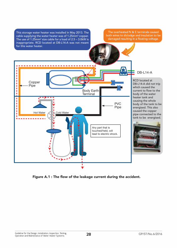
A.1.2 Improper terminations at the water heater
Background
The water heater was only protected by an RCD with a residual operating current at the main switch board with a tripping current of 100mA. It was of a model with approval from the Energy Commission.
Water heater was rated at 2.5 – 3.0 kW. The water heater circuit had two units of 2-pole switches, modified for the circuit to have a 2 way switching arrangement. The cable supplying the water heater was of 1.25 mm2 copper. The socket outlet and the cable in the water heater circuit were not of approved types.
Findings
The poor termination and the undersized wiring resulted in over heating at the termination point. This caused the cables to dislodge and for their insulation to be damaged. Subsequently the live cable touched the body of the water heater causing it and the parts connected to it to rise in potential. The RCD with a residual operating current at the main switch board was not functioning. Two victims received fatal shocks when coming into contact with the metallic part of the shower hose.
Figure A.1: The flow of the leakage current occurred during the accident.
Figure A.2 and Figure A.3 shows the condition of the appliances and its wiring system that was affected by the accident.
28Guideline for the Design, Installation, Inspection, Testing, Operation and Maintenance of Water Heater Systems
GP/ST/No.6/201628
Figure A.1 : The flow of the leakage current during the accident.
CopperPipe
PVCPipe
Body EarthTerminal
Hot Water Cold Water
Any part that is touched/held, will lead to electric shock.
RCD located at DB-L14-A did not trip which caused the current to flow to the body of the water heater tank and causing the whole body of the tank to be energised. This also caused the copper pipe connected to the tank to be energised.
This storage water heater was installed in May 2013. The cable supplying the water heater was of 1.25mm2 copper. The use of 1.25mm2 size cable for a load of 2.5 – 3.0kW is inappropriate. RCD located at DB-L14-A was not meant for this water heater.
DB-L14-A
The overheated N & E terminals caused both wires to dislodge and insulation to be
damaged resulting in a floating voltage.

Guideline for the Design, Installation, Inspection, Testing, Operation and Maintenance of Water Heater Systems
GP/ST/No.6/201629
Figure A.2: The burnt condition of connector at the water heater.
Figure A.3: Metallic water heater hose that was still in an energized condition after the accident.

30Guideline for the Design, Installation, Inspection, Testing, Operation and Maintenance of Water Heater Systems
GP/ST/No.6/201630
Distribution Board(RCD 100mA not trip)
Metalicshower
hose
Direction ofleakage current
Earth wireLive wireFlow of fault current
Figure A.4
Live wire short circuit to body/casing of lamp
fitting
Water heater type Instantaneous water heater
Where Residence
When June 2015
AccidentFatal and non fatal accident where victims experienced electrical shock when holding metallic shower hose in a bathroom and also while helping the electrocuted victim.
A.1.3 Use of conducting shower hose
BackgroundThe water heater was protected by RCD having residual operating current of 100mA and not 10mA as required under the law. The water heater was of a model with approval from the Energy Commission.
FindingsShort circuit from the other part of house wiring causes the body and the metallic shower hose of the water heater become live. This has electrocuted the victim when holding the metallic hose. At the same time, RCD with residual operating current of 100mA do not trip. One victim received fatal shocks and three other victims suffer injuries when coming into contact with the metallic part of the shower hose and touching victim’s body.
Figure A.4: The flow of leakage current during the accident.

Guideline for the Design, Installation, Inspection, Testing, Operation and Maintenance of Water Heater Systems
GP/ST/No.6/201631
Water heater type Storage water heater
Where A resort
When December 2014
Accident Water heater exploded – a non fatal accident
A.1.4 Explosion of water heater
Background
Water heater was installed around middle of 2010. It was of a model with approval from the Energy Commission. It was purchased from the supplier and installed by the client’s technician. The water heater had a guarantee period of 6 months.
Findings
There were no records of maintenance. There was no RCD with a residual operating current with an operating current of 10mA installed in the water heater circuit. The drain valve was found to be closed. (By referring to the water heater Operating Manual, the drain valve should always be in an open position).
The last user of the water heater did not/forgot to turn off the electricity supply to the water heater after using it.
The following safety features did not operate: -i. PRV and Drain Valve (the drain valve was closed)ii. Thermostat iii. Thermal Cut-Out

32Guideline for the Design, Installation, Inspection, Testing, Operation and Maintenance of Water Heater Systems
GP/ST/No.6/201632
Bathroom
Alternative
LV-Assembly
M M
M M
PE
PE
3
3
3
4 4
11
LV-Assembly
C4
C7
2
1
1
2
2
5
2
C1 C2 C3
C5
5 Ground floor
Insulating insert
T1T2 T2
5
B
1st floor with a bathroom
C6
LPS LPS
3
Annex B(Informative)
Illustration of earthing arrangement, protective conductors and protective bonding conductors

Guideline for the Design, Installation, Inspection, Testing, Operation and Maintenance of Water Heater Systems
GP/ST/No.6/201633
KeyM Exposed-conductive-part Conductive part of equipment which can be touched and which is not normally live, but
which can become live when basic insulation fails [IEV 195-06-1-10]C Extraneous-conductive-part Conductive part not forming part of the electrical installation and liable to introduce an
electric potential, generally the electric potential of a local earth [IEV 195-06-11]
C1 Waterpipe, metal from outside
C2 Waste, water, metal from outside
C3 Gas pipe with insulating inset, metal from outside
C4 Air-conditioning
C5 Heating-system
C6 Waterpipe, metal e.g. in a bathroom
C7 Extraneous-conductive-parts in arm's reach of exposed-conductive-parts
B Main earthing terminal (main earthing busbar) Terminal or busbar which is part of the earthing arrangement of an installation and
enabling the electric connection of a number of conductors for earthing purpose [IEV 195-02-33]
T Earth electrode Conductive part, which may be embedded in a specific conductive medium, e.g. concrete
or coke, in electric contact with the earth [IEV 195-02-01]
T1 Foundation earth
T2 Earth electrode for LPS if necessary
1 Protective conductor Conductor provided for purposes of safety, for example protection against electric shock [IEV 195-02-09]
2 Protective bonding conductor Protective conductor provided for protective-equipotential-bonding [IEV 195-02-10]
3 Protective bonding conductor for supplementary bonding
4 Down conductor of a lightning protection system (LPS)
5 Earthing conductor Conductor which provides a conductive path, or part of the conductive path, between a
given point in a system or in an installation or in equipment and an earth electrode [IEV 195-02-03]
NOTE: For the purpose of this standard, an earthing conductor is the conductor which connects the earth electrode to the point of the common equipotential bondind system, usually the main earthing terminal

34Guideline for the Design, Installation, Inspection, Testing, Operation and Maintenance of Water Heater Systems
GP/ST/No.6/201634
AcknowledgementsNAME ORGANISATION
Mohd Elmi Bin Anas (Chairman) Suruhanjaya Tenaga
Ir Nur Ali Za bin Omar Suruhanjaya Tenaga
Iffah Hannah Bt Muluk Suruhanjaya Tenaga
Haji Abdul Aziz bin Abdul Rahman Suruhanjaya Tenaga
Ir Fairus binti Abdul Manaf Suruhanjaya Tenaga
Mohd Nawawi Said Abdullah Suruhanjaya Tenaga
Ir Amir Hassan Suruhanjaya Tenaga
Ir Amir Faisal Khamshah Suruhanjaya Tenaga
Joanna Lenta Samana (Secretary) Suruhanjaya Tenaga
Rohaida Bt Mat Lazim Suruhanjaya Tenaga
Norsheila binti Idris Suruhanjaya Tenaga
M. Zamri Mustaffa SIRIM QAS International Sdn Bhd
Khairul Azhar Bin Abd Rahman SIRIM QAS International Sdn Bhd
Amy Suraya Abu Samah SIRIM QAS International Sdn Bhd
Marina bt Mahdar SIRIM STS Sdn Bhd
Ir Francis Xavier Jacob IEM
Ir Tejinder Singh IEM
Ir Lim Kim Ten IEM / TEEAM
Tee Tone Vei TC5, WG2 / TEEAM
Ir Looi Hip Peu TC10, TC7 / TEEAM
Ir Chew Shee Fuee TEEAM
Ir Yau Chau Fong TEEAM / IEM
Dr Che Hang Seng TEEAM
Winnie Khong TEEAM
Ho Khai Hong TEEAM
Ir Ahmad Rashidi bin Zainudin ACEM
M Azmi Bin Tahir Panasonic
Chan Toong Mook SEERS
Mohd Fairuz Bin Mohd Yusof SEERS
Abd Aziz Bin Kadir STIEBEL
Deric Tan Nu-Vale Trading
Cheng Chee Sen Maxvic Sdn Bhd
Chaw Huey Yen Intrix Renewable Sdn Bhd

Guideline for the Design, Installation, Inspection, Testing, Operation and Maintenance of Water Heater Systems
GP/ST/No.6/201635
Gan Kok Heng KHIND
Boo Sian Cong Aerogaz Sdn Bhd
Mazley Faizal Bin Mohamed Bee Best Marketing Sdn Bhd
Andy Tan Joven Electric Co. Sdn Bhd
Tan Joo Yee Joven Electric Co. Sdn Bhd
Yeo Peng Hwa United Alpha Industries Sdn Bhd
Lim Tow Hsing Showertec Industries Sdn Bhd
Choo Wei Seng Showertec Industries Sdn Bhd, WG2
Yeo Yao Sheng Showertec Industries Sdn Bhd
Ng Eng Heng Centonia Industries Sdn Bhd
Eric Lee Wai Mun Centonia Industries Sdn Bhd
Mohd Basrullah Centonia Industries Sdn Bhd
Leom Jiew Fook Centonia Industries Sdn Bhd
Lee Kian Boon Alpha Electric Co. Sdn Bhd
Tan Kok Wai Alpha Electric Co. Sdn Bhd
Phyllis Lim FIMACO Sdn Bhd
Nicholas Tang Sheng Ling Ng FIMACO Sdn Bhd
Dylan Chua ELECTROLUX
Cheong Kok Chun Hitachi Sales (M) Sdn Bhd
Tony Leong Persatuan Kekompetenan Penjaga Jentera Pendawai Elektrik Perak (PKPPE)
Ir Fong Chin On Persatuan Kekompetenan Penjaga Jentera Pendawai Elektrik Perak (PKPPE)
Stanley Wong Persatuan Kekompetenan Penjaga Jentera Pendawai Elektrik Perak (PKPPE)
Nick Liew Persatuan Kekompetenan Penjaga Jentera Pendawai Elektrik Perak (PKPPE)
Wong Seak Wai Persatuan Kekompetenan Penjaga Jentera Pendawai Elektrik Perak (PKPPE)
Chew Kam Hoong Persatuan Kekompetenan Penjaga Jentera Pendawai Elektrik Perak (PKPPE)
Khaw Yee Kuan Persatuan Kekompetenan Penjaga Jentera Pendawai Elektrik Perak (PKPPE)
Choong Soon Yean Persatuan Kekompetenan Penjaga Jentera Pendawai Elektrik Perak (PKPPE)
Leong Kok Wah Persatuan Kekompetenan Penjaga Jentera Pendawai Elektrik Perak (PKPPE) / TEEAM
NAME ORGANISATION

36Guideline for the Design, Installation, Inspection, Testing, Operation and Maintenance of Water Heater Systems
GP/ST/No.6/201636
REGIONAL OFFICE ADDRESS CONTACT
ST Regional Office (Pulau Pinang, Kedah & Perlis)
Tingkat 10, Bangunan KWSP, 13700 Seberang Jaya, Butterworth, PULAU PINANG
Tel: 04 - 398 8255Fax : 04 - 390 0255
ST Regional Office(Perak)
Tingkat 1, Bangunan KWSP, Jalan Greentown, 30450 Ipoh PERAK
Tel: 05 - 253 5413Fax : 05 - 255 3525
ST Regional Office(Kelantan & Terengganu)
Tingkat 6, Bangunan KWSP, Jalan Padang Garong, 15000 Kota Bharu KELANTAN
Tel: 09 - 748 7390Fax : 09 - 744 5498
ST Regional Office (Pahang)
Tingkat 7, Kompleks Teruntum, Jalan Mahkota, 25000 Kuantan PAHANG
Tel: 09 - 514 2803Fax : 09 - 514 2804
ST Regional Office(Selangor, Kuala Lumpur Putrajaya)
Tingkat 10, Menara PKNS, No. 17, Jalan Yong Shook Lin, 46050 Petaling Jaya SELANGOR
Tel: 03 - 7955 8930Fax : 03 - 7955 8939
ST Regional Office(Negeri Sembilan & Melaka)
Tingkat 3, Wisma Perkeso, Jalan Persekutuan, MITC, 75450 Ayer Keroh, MELAKA
Tel: 06 - 231 9594Fax : 06 - 231 9620
ST Regional Office(Johor)
Suite 18A, Aras 18, Menara ANSAR, 65 Jalan Trus, 80000 Johor Bharu JOHOR
Tel: 07 - 224 8861Fax : 07 - 224 9410
ST Regional Office(West Coast of Sabah)
Tingkat 7, Bangunan BSN, Jalan Kemajuan, 88000 Kota Kinabalu SABAH
Tel: 088 - 232 447Fax : 088-232444
ST Regional Office(East Coast of Sabah)
Tingkat 3, Wisma Saban, KM12 W.D.T. No. 25, 90500 Sandakan SABAH
Tel: 089 - 666 695Fax : 089-660279
MAIN OFFICE ADDRESS: -Energy Commission No. 12, Jalan Tun Hussein, Precinct 2,62100, Putrajaya.Toll Free Number : 1-800-2222-78 Telephone : 03-8870 8500 Fax : 03-8888 8637

www.st.gov.my
SURUHANJAYA TENAGA(ENERGY COMMISSION)No. 12, Jalan Tun Hussein, Precinct 2,62100 Putrajaya, Malaysia
Toll Free Number: 1-800-2222-78 (ST)Tel: (03) 8870 8500 Fax: (03) 8888 8637