design, modelling and simulation of maritime uav-vtol flight dynamics
TRANSCRIPT

Design, Modelling and Simulation of Maritime UAV-VTOL Flight Dynamics
Jun Cao1,a and Amir Anvar 1,b 1The University of Adelaide, School of Mechanical Engineering
SA 5005 AUSTRALIA
Emails: [email protected], [email protected]
Keywords: UAV, VTOL, Structure, Maritime, Aircraft, Design, Micro-sonobuoy, Model, Flight
Dynamics
Abstract. An Unmanned Aerial Vehicle (UAV) is referred to as a remotely piloted aircraft or an
unmanned aircraft which can be navigated with human operator in the loop. This paper discusses
the design of a UAV with Vertical Take-Off and Landing (VTOL) capability for Maritime
applications. The design provides a means for surveillance and communication in Maritime
applications. The VTOL-UAV utilises a five-rotor propulsion system that can be launched from
confined platforms such as ship-decks. The intended applications of this M-UAV drove the
development of an innovative landing system which in the case of emergencies can allow the M-
UAV’s soft and potential landing on the water surface. The other functionalities of this UAV are its
capabilities to deploy communication Micro-sonobuoys which allows for communication with
underwater Robot(s) via Operator in the loop. In this paper we also discuss the process of structural
design modelling and evaluation of the development of the Maritime Unmanned Air Vehicle.
Introduction
A VTOL-UAV is an aerial vehicle that does not require an onboard crew to operate. It is therefore
a useful tool in many operations, including search and rescue missions, environmental assessments,
possible sonobuoy deployment, and remote communications with operator in the loop and so on.
However, the UAVs can also be used to help people perform secure research and environmental
assessment within a natural disaster zone, (for example, earthquake and high radiation level
environment) (Anderson 1981). Additionally VTOL-UAVs have better maneuverability than other
types of UAVs and this will enhance the feasibility of the application. One example is the use of
UAVs’ after the earthquake and tsunami in Fukushima-Japan. By using VTOL-UAVs’ rescue
search processes could be enhanced as UAVs can be designed in micro size to access tunnels and
other gaps in demolished buildings (Eisenbeiss 2004) where conventional search methods cannot
reach. Additionally with the advantage of UAVs’ remote control capability people can undertake
environmental assessment without entering high radiation areas, thereby improving search safety.
Literature review
A review of the literature reveals that previous and existing designs of UAVs with vertical takeoff
and landing capability use a similar propulsion concept. The conventional configuration utilises a
certain amount of rotors for driving blades to produce sufficient lift for the aircraft. However, using
a different type of rotors will lead to different airframe design configurations. Several design
configurations have been selected for review such as single rotor and quadrocopters.
Applied Mechanics and Materials Vols. 152-154 (2012) pp 1533-1538Online available since 2012/Jan/24 at www.scientific.net© (2012) Trans Tech Publications, Switzerlanddoi:10.4028/www.scientific.net/AMM.152-154.1533
All rights reserved. No part of contents of this paper may be reproduced or transmitted in any form or by any means without the written permission of TTP,www.ttp.net. (ID: 144.32.128.14, University of Newcastle, Callaghan, Australia-09/10/13,23:20:47)
Single rotor configuration is the most conventional VTOL UAV configuration and has been
investigated for nearly 80 years. In single rotorcraft the main rotor is used to generate sufficient lift
for the whole aircraft. The small tail rotor is used to counter the rotation torque produced by the
main blade. As a result of their mature design, the flight dynamics of this configuration is well
understood.
Single rotor configurations usually have high stability due to their large main rotor in size. The
other main disadvantage of a single rotor UAV is that a large rotor is required to be designed in
order to meet the design specification. For example the Joker 2 helicopter has a total weight of
4.89kg however the main rotor has a diameter of 1549mm (Stingu, 2010). The design specification
of the UAV-VTOL for this project needs the capability of carrying a sonobuoy with the weight of
2kg as payload. Based on this data the size of the expected rotor to be designed would be within the
vicinity of 1500mm in diameter, which would cause design difficulties, such as in manufacturing as
well as limiting the possibility of purchasing from the local market.
A quadrocopter, also called a quadrotor or quadrotor-helicopter, is an aircraft that utilizes four
rotors to propel the vehicle. Generally quadrocopters have the capability of stationary hover and
omnidirectional flight, whereby pitch angle, roll angle, yaw rate and thrust can be controlled
independently. This capability solves the issue raised by single rotor and tandem rotor UAVs
regarding the relationship between the stability and maneuverability. Recently quadrocopters have
become more and more popular due to their large payload capacity made by the large amounts of
lift that can be generated by those four rotors (AirRobot 2007, Stingu 2010, Goss, T. Nguyen, T. et
al, 2010) presently. AirRobot AR100-b is the largest commercial quadrocopter. It can fly silently
through the air or hover while transmitting live images to the operator at the ground station within
1km. However the maximum payload weight of this aircraft is limited below 200g (AirRobot
2007). Additionally its agility and position-holding precision have made that type of UAV widely
used for many tasks such as surveillance, rescue missions and payload delivery. However
quadrocopter control theory has become a popular research field in many Universities. According
to Sikiric 2008, most of these problems focus on the control of small, lightweight quadrocopters.
As most small scale quadrocopters use fixed pitch propellers to generate lift. This type of
configuration will ease the navigational control system flight dynamics as the orientation of the
aircraft can be controlled by changing the propeller’s rotational speed.
Design
The literature review introduced different types of existing design concepts which were discussed
in detail. In this section the overall design concept for the
maritime VTOL-UAV project will be introduced and
evaluated.
An important issues related to the VTOL UAV design is
how to balance the relationship between the stability and
manoeuvrability of the aircraft. The designed UAV needs
to be relatively stable both in forward flight and in hover as
well as the need to be agile, capable of
hovering in low altitude and meeting the
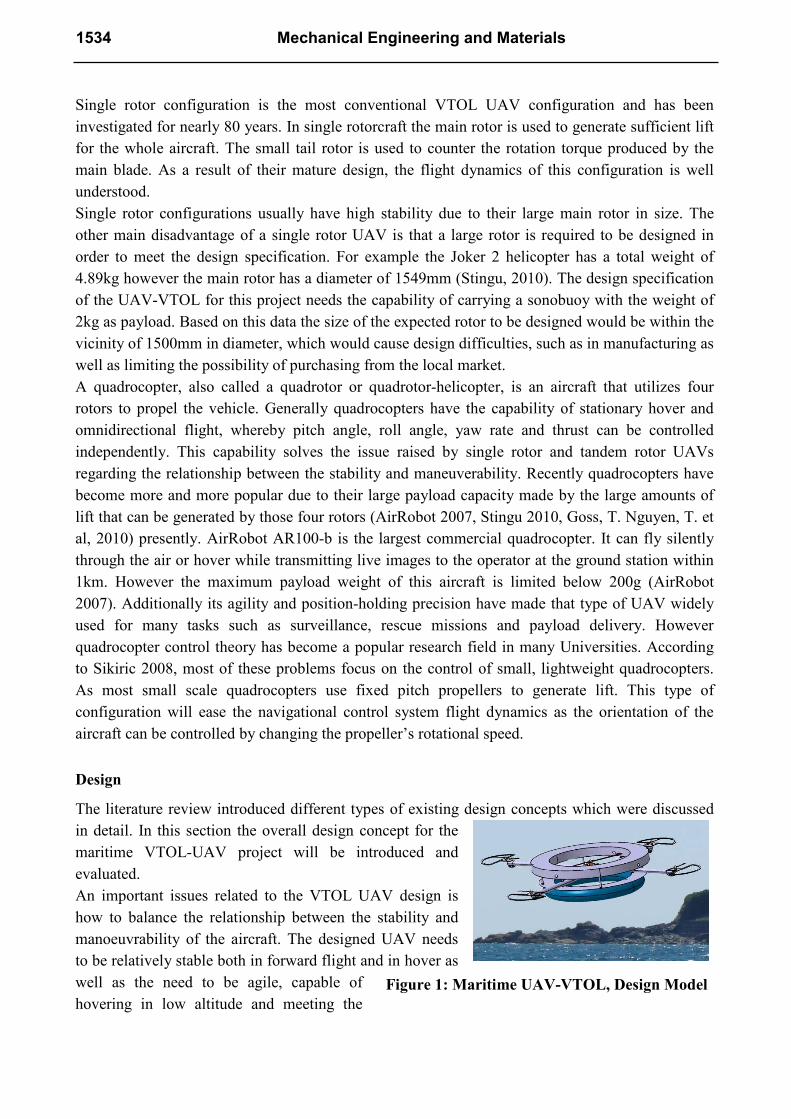
Figure 1: Maritime UAV-VTOL, Design Model
1534 Mechanical Engineering and Materials
requirement of fundamental control manoeuvres such as slow turns, forward flight. Additionally
innovation is an important issue to be considered. If similar designs can be found within the local
market the design will be considered as less innovative.
According to Salazar et al (2009) a rotorcraft will become more stable and efficient when the rotor
area is increased. Therefore the designed UAV needs to have more rotors in order to increase the
stability of the aircraft. However, this rotor leads to another issue which is the limitation of the
aircraft’s manoeuvrability. In order to tackle this issue, quadrocopter flight dynamics will be
applied to the chosen design as this type of configuration will ease the control, as the orientation of
the aircraft can be controlled by changing the propeller’s rotational speed. Thus the prototype
design needs to have more than four rotors to power the aircraft.
Hence a five-rotor configuration will be considered in the first step of design. Figure 1 shows the
conceptual design for this UAV. An air tube will be used in the design for the landing gear, as this
device acts as a shock absorber during hard landing. By using this feature, electronic components
which are located inside the ring shaped cage can be protected from shock.
Five-rotor and quadrotor configurations employ rotor speed control for orientation control.
Therefore the flight dynamics of a five-rotor configuration is similar to that of a quadrotor system.
This means that manoeuvring can be achieved with no extra mechanical complexity, weight penalty
or energy loss.
A review of the existing landing system in the market indicates that most landing systems are
designed to be hard landing. One of the major disadvantages for such designs is that if an aircraft
lands in an emergency scenario, the UAV will crash into the ground instead of landing safely.
Consequently both the airframe and electronic components will be damaged severely if the
approaching speed is high. By utilizing an air tube to construct a landing gear this problem will be
resolved.
Additionally air tube incorporation into the landing gear design, will minimize the landing shock
generated during landing.
Alternatively air tubes will enable the possibility of water surface landing if the air tube is large
enough as mentioned in the project definition. This
type of capability will be an additional innovation to
the five rotor configuration for the maritime UAV-
VTOL. However the ability to land on a water surface
will depend on the size of the landing tube selected
and the total weight of the aircraft. The air tube will be
fastened on the UAV by attaching the cable tires so
that there will be no extra components to be designed
for mounting landing system. One of the major
advantages of an air tube landing system is the
flexibility of the assembly.
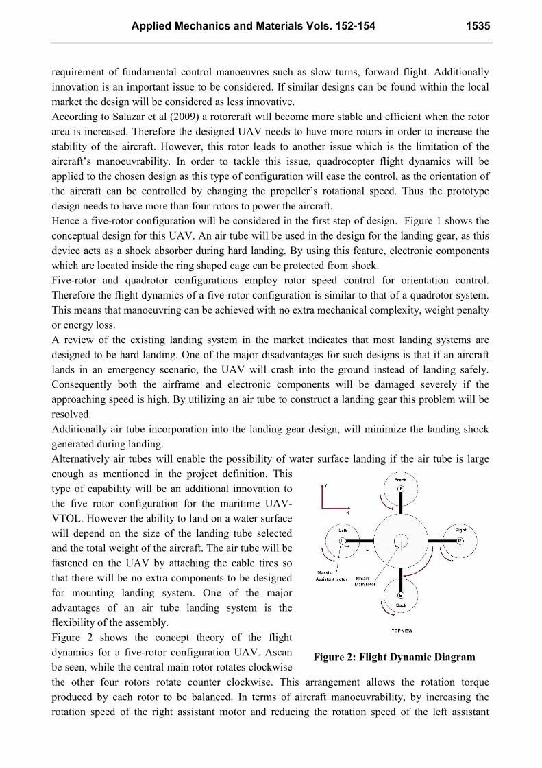
Figure 2 shows the concept theory of the flight
dynamics for a five-rotor configuration UAV. Ascan
be seen, while the central main rotor rotates clockwise
the other four rotors rotate counter clockwise. This arrangement allows the rotation torque
produced by each rotor to be balanced. In terms of aircraft manoeuvrability, by increasing the
rotation speed of the right assistant motor and reducing the rotation speed of the left assistant
Figure 2: Flight Dynamic Diagram
Applied Mechanics and Materials Vols. 152-154 1535

motor, so that the rolling dynamics of the aircraft can be achieved. Additionally increasing the
RPM of the rear assistant motor and reducing the rotation speed of the front assistant rotor aircraft
can achieve pitching dynamics. This is discussed in the dynamic modelling derivation section in
more detail.
Dynamic modelling for hovering
The dynamic altitude model for the five-rotor UAV was derived from Newton’s Laws (Nelson
1998).The rotation torque produced by the main rotor in the center is cancelled out by four counter-
rotating rotors on the side, which removes any coupling between the pitch and roll dynamics.
However the total collective thrust, , is the sum of all five rotor forces, as given below:
(1)
This collective thrust will be equal to the total weight of the aircraft. Otherwise, when the vehicle is
in the takeoff and landing hovering phase, the dynamic control can be varied even with the pilot’s
initiative inputting towards variance rotation speed of each rotor. By reviewing the power plant
design, total thrust can be calculated by using the equation 1:
As the main rotor can provide 7500g lift for the aircraft therefore:
However, according to the calculations, the assistant motor can generate 1900g lift during the
operation:
Then total thrust would be
Test results
Designing a UAV will involve the selection of different components such as motors, propellers and
batteries. Although the performance of each component has been announced by the manufacturer,
conducting a test to prove the performance will be necessary before installing them onto the real
airframe.
Thrust capability analysis is of primary importance to ensure the thrust generated by the UAV is
sufficient for flight and meets the flight requirement. A propulsion test will allow the experimental
determination of the maximum thrust that can be achieved by a chosen propulsion system and
hence the thrust to weight ratio.
Figure 3: Testing equipment
1536 Mechanical Engineering and Materials
thru
st (
kg
)
Rotation Speed (RPM)
throetical
data
test data thru
st (
kg
)
Rotation Speed (RPM)
theoreticl
a data
test data
In this project, a static thrust test was conducted. The test rigid includes a pivoted beam with the
motor mount on one end and a strain gauge on the other end. Therefore the thrust generated by the
rotor is measured by reading the voltmeter that has been connected to the strain gauge. Additionally
in order to control the rotation speed of the motor, the speed controller is connected to a signal
generator. A tachometer is important for the propulsion test as the rotation speed is one of the most
important data to be collected during the operation. In order to simplify the test layout, a laser
tachometer is used as it has the simplest setup. Figure 3 above shows the laser tachometer used in
the test, the test rigid layout, electronic components and the overall test layout respectively. The test
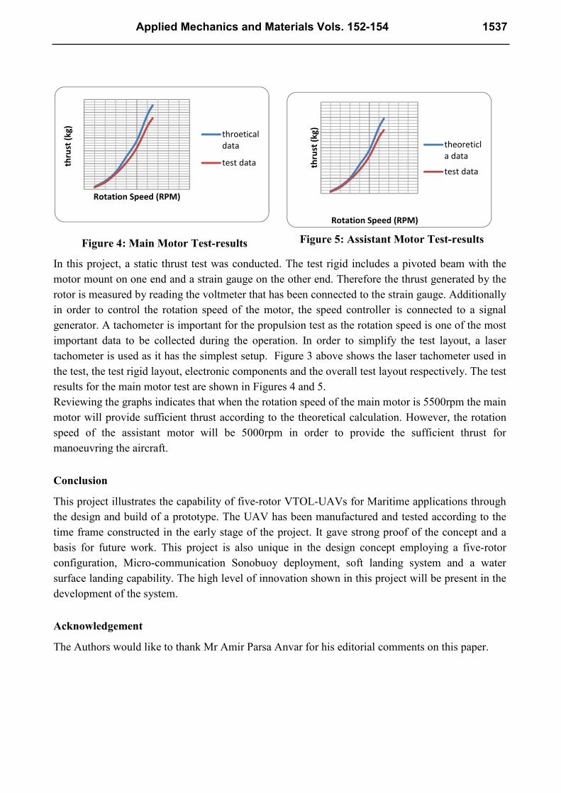
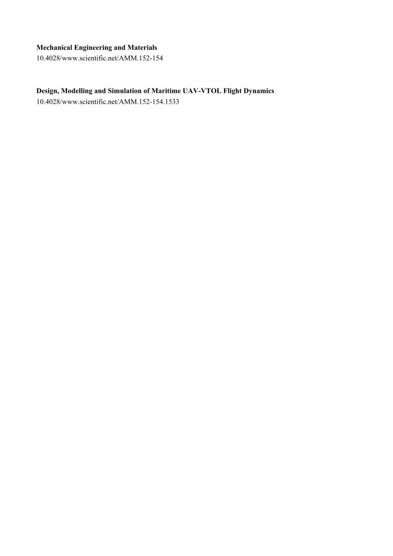
results for the main motor test are shown in Figures 4 and 5.
Reviewing the graphs indicates that when the rotation speed of the main motor is 5500rpm the main
motor will provide sufficient thrust according to the theoretical calculation. However, the rotation
speed of the assistant motor will be 5000rpm in order to provide the sufficient thrust for
manoeuvring the aircraft.
Conclusion
This project illustrates the capability of five-rotor VTOL-UAVs for Maritime applications through
the design and build of a prototype. The UAV has been manufactured and tested according to the
time frame constructed in the early stage of the project. It gave strong proof of the concept and a
basis for future work. This project is also unique in the design concept employing a five-rotor
configuration, Micro-communication Sonobuoy deployment, soft landing system and a water
surface landing capability. The high level of innovation shown in this project will be present in the
development of the system.
Acknowledgement
The Authors would like to thank Mr Amir Parsa Anvar for his editorial comments on this paper.
Figure 4: Main Motor Test-results Figure 5: Assistant Motor Test-results
Applied Mechanics and Materials Vols. 152-154 1537

References
[1] Airrobot, (2007), Micro Unmanned Aerial Vehicle with autonomous flight and navigation
capabilities and modular payloads. Airrobot US, Inc, New York.
[2] Anderson, S., (1981), Historical Overview of V/STOL Aircraft Technology. NASA Technical
Memorandum, 2(80), p.81.
[3] Eisenbeiss, H., (2004), A mini unmanned aerial vehicle (UAV): System overview andimage
acquisition’, in Proceedings of the International Workshop on Processing andVisualization using
high resolution imagery, Pitsanulok, Thailand.
[4]Coleman, C.P., (1997), A survey of theoretical and experimental coaxial rotor aerodynamic.
California, Ames Research Center.
[5]Goss, T. Nguyen, T. et al., (2010), Design, Build and Implementation of a VTOL Maritime UAV,
School of Mechanical Engineering, University of Adelaide, Australia.
[6] Stingu, P., (2010), hardware and software system for UAV control, Automation and Robotics
Research Institute, the university of texas, USA.
[7] Dimanlig, A. &Meadowcroft, E. et al., (2007), Computational Modelling ofthe CH-47
Helicopter in Hover’, In Proceedings of the HPCMP Users Group ConferenceHigh Performance
Computing Modernization Program: A Bridge to Future Defence,Pittsburgh, Pennsylvania, United
States, pp 98 – 103.
[8] Stone, H, Clarke, G., (2001), The T-Wing: A VTOL UAV for Defense and CivilianApplications,
in the proceedings UAV Australia Conference, Melbourne, February 2001.
[9] Salazar, S., Romero, H. et al, (2009), Modeling and Real-Time Stabilization of an Aircraft
Having Eight Rotors, instituto de investigacioneselectrocas, Palmira, Mexico.
[10] Nelson, R., (1998), Flight stability and automatic control second edition, McGraw-Hill Higher
Education companies, USA.
1538 Mechanical Engineering and Materials
Mechanical Engineering and Materials 10.4028/www.scientific.net/AMM.152-154 Design, Modelling and Simulation of Maritime UAV-VTOL Flight Dynamics 10.4028/www.scientific.net/AMM.152-154.1533