design of a new torso-joint for the humanoid robot...
TRANSCRIPT

Journal of Mechanical Engineering and Automation 2012, 2(4): 58-64 DOI: 10.5923/j.jmea.20120204.02
Design of a New Torso-Joint for the Humanoid Robot ARMAR
Christian Sander*, Thomas Soworka, Albert Albers
IPEK - Institute of Product Engineering, Karlsruhe Institute of Technology, 76131, Karlsruhe
Abstract The development of a humanoid robot within the scope of the Collaborative Research Center 588 (SFB 588) has the objective of creating a machine that can cooperate with humans closely. For designers, computer scientists and me-chanical and electrical engineers this development area presents great challenges. In contrast to commercial industrial ro-bots - for which mechanical rigidity, precision, high velocities and accelerations are primary requirements - the key aspects here are prevention of hazards to users, a motion space that corresponds to that of human beings, and a lightweight design. In order to meet these requirements, the robot must have humanlike appearance, motion space, and dexterity. Additionally, its kinematics should be familiar to the user, and its motions predictable, so as to encourage inexperienced persons to inter-act with the machine. The human spine offers great flexibility and is loaded with the weight of at least the whole upper body. On this account the emulation of the human upper body movement describes one of the most advanced issues in hu-manoid robot design. For the next generation of the humanoid robot ARMAR, a new concept to achieve a better flexibility in the robot's upper body movement has been done. This new torso-joint offers high stiffness, better accuracy and simulta-neously reduces weight and construction volume. Spring elements are used to save energy and to support the engines. In this paper the new mechanical design and first calculated results, considering energy saving potential and stiffness, are de-scribed in detail.
Keywords Torso-Joint, Humanoid, Robotic, Armar
1. Introduction Robots are widely spread in the industry. They generally
have to meet requirements such as high payload, stiffness, accuracy, repeatability, acceleration and finally a high speed. Their design and function was adequate tested by thousands of products. On the contrary humanoid robots are only available as prototypes which can be traced back to the different requirements. The key goal for humanoid robots is not accuracy, but the ability to cooperate with humans. Therefore high standards are set for sensors and control of its movements. Nevertheless a humanlike appearance is important for the human acceptance of robots in everyday life. It also helps the robot to fit in the human environment. So the robot's kinematic properties and range of movements must be adjusted to humans[1].
Because the mechatronic design of a humanoid robot is fundamentally different from that of traditional industrial robot, the design of the components has to start often from scratch. The high power density of the human muscles and high strength of the bones have to be replaced by
* Corresponding author: [email protected] (Christian Sander) Published online at http://journal.sapub.org/jmea Copyright © 2012 Scientific & Academic Publishing. All Rights Reserved
mechanical components and special mechanical solutions which have to fit into the small design space of the human body. Under these circumstances, the development of hu-manoid robots is a great challenge.
Figure 1. ARMAR IIIa[2]
Considering the above mentioned points, humanoid ro-bots have to act and to move similar to humans. Besides arms and legs, it is also important to have a moveable upper body. It enables the robot to re-adjust the center of gravity which is important for fast biped walking and offers a wider range of motion. The great importance of a moveable upper

Journal of Mechanical Engineering and Automation 2012, 2(4): 58-64 59
body leads to persistent consideration about the design of the upper body movement. One way to realize the upper body movement is the so called "Torso-Joint". It offers sev-eral degrees of freedom in the upper body by a compact construction. Thereby the upper body motion can be distin-guished generally into three degrees of freedom (DOF): Pitch, forward/ backward deflection of the spine. Roll, sidewise swaying of the upper body. Yaw, rotation of the upper body along the spine.
In this paper a new design of a differential Torso-Joint for the new robot ARMAR V is presented. The goals of the development project are both to improve the motion effi-ciency and to achieve a humanlike appearance. The new mechanical design is described in detail completed by a design concept of a prototype.
1.1. The humanoid robot ARMAR
The Collaborative Research Center 588 "Humanoid Ro-bots - Learning and Cooperating Multi-Modal Robots" was established by the "German Research Foundation" (DFG) in Karlsruhe in May 2001. In this project, scientists from dif-ferent academic fields develop concepts, methods, and con-crete mechatronic components for different humanoid ro-bots called ARMAR (see figure 2). These robots can share their working space with humans. The long-term target is the interactive work of robots and humans to jointly accom-plish specified tasks.
For instance, a simple task like putting cups into a dis-hwasher requires sophisticated skills in cognition and the manipulation of objects. Communication between robots and humans should be possible in different ways, including speech, touch, and gestures, thus allowing humans to inte-ract with the robots easily and intuitively. As this is the main focus of the Collaborative Research Center, a huma-noid upper body on a holonomic platform for locomotion has been developed. It is planned to increase the mobility of ARMAR by replacing the platform by legs, which will lead to great modifications of the upper body.
1.2. State of the art and motivation
As already mentioned a humanlike design is important for a humanoid robot so that the robot fits perfectly in a human working space and is suitable to interact in this environment. According to this fact the operating space of the upper body must be similar to the human one.
The human spine consists of 24 moveable vertebral bodies and each of them allows a small range of motion. But com-bined, they allow a great flexibility of the human upper body. Several research projects like Kotaro[3] respectively Koji-ro[4] are following similar concepts for a robot spine. Five vertebral bodies are connected with spherical joints. Tension springs and silicon rubber parts are attached to the vertebral bodies. With these elasticity and viscosity the motion of the upper body is humanlike gentle und supple. Ropes connected with the rips are used to generate the torque for the upper body movement. Nevertheless the recreation of a spine is
very complex and can easily exceed the reasonable range of technical feasibility, especially for autonomous humanoids like ARMAR. Space is needed in the upper body to ac-commodate batteries and processors. Especially in ARMAR, pump and pressure tank, which are needed to drive the nu-merous joints in the robot’s hands, have to find place in the robot's torso. For this reason a more compact solution for the whole upper body movement has to be found.
In most state-of-the-art humanoids like LOLA[5], ICUB[6], Reem-B[7], HRP-4c[8] the upper body move-ments are accumulated in one joint. Such "Torso-Joint" allows up to three degrees of freedom (DOF) which expand the range of motion and enable the relocation of the gravity center which is also of importance for biped walking.
The concept of a Torso-Joint can be distinguished between a serial and differential arrangement. A serial arrangement of the DOFs allows an easy regulation on speed and torque for each DOF separately. But for each of the motions (Pitch, Roll, Yaw) a separate engine unit has to be integrated. But the integration of three electrical drives which fulfill the high torque and speed requirements, leads to large and heavy constructions. Thus the humanoids Lola[5] and ARMAR IV are offering only two DOFs in this joint.
A parallel kinematic, like it is used in ICub[6], distributes the high torque for the roll and pitch movement on two drives. Hence, the drive units can be designed smaller. This offers the necessary space in the robot's torso to house other com-ponents.
1.3. Design goals and system of objectives
Currently, ARMAR V the next generation of robots of the research center 588 is been developed. To design a new torso-joint it is important to define the design goals and the system of objectives. A humanlike design space and espe-cially the ability to move like a human are main goals in the Collaborative Research Center 588. Requirements include the expansion of the movement skills to get even closer to the human kinematics. Specifically, more degrees of freedom (DOF) have to be added to the kinematics of the robot. To increase the operation range and the availability of the sys-tem, the energy efficiency has to be increased. To achieve this challenge, new drive concepts have to be developed and every structural component has to be optimized to get a lightweight design but still a high stiffness.
A torso-joint has to accelerate the whole mass of the upper body. It is difficult to optimize this movement because the center of mass differs with the position of the arms and with it the requirements on the motors. After a mass estimation of ARMAR IV the design goal for the pitch and roll motion was set to a maximum torque of 120 Nm. This allows the robot to act with outstretched arms and gives a sufficient acceleration around the dead center position to react on mass displace-ment during walking. To be able to pick the right motors and gearboxes the needed torques have to be calculated. In Fig-ure 2 the torque is plotted against the two motion angles θ=roll and α=pitch.

60 Christian Sander et al.: Design of a New Torso-Joint for the Humanoid Robot ARMAR
Figure 2. Torque[Nm] over angle[°]
The design and especially the humanlike appearance are still fixed requirements to ensure the acceptance of the robot by people. This requires the strict compliance with the hu-man "design space", which is due to the power density and the size of available sensors and actuators a great challenge. For the complete joint, the maximum width is 180 mm, the height 150 mm and the depth also 150 mm. In the table be-low the motion space and corresponding torques are listed.
Table 1. Requirements
Degree of Freedom Torque[Nm] Motion Space[°] Roll 120 ±15 Pitch 120 +60/-10 Yaw 100 ±120
superposed Motion 120
2. New Concept
Figure 3. Differential Gearbox
The new concept for ARMAR's torso-joint (see figure 4) picks up the advantage of a differential gearbox (see figure 3) which was also used in the iCub concept. It's a parallel ki-nematic which realizes the roll and pitch movement, i.e. the two engines are working always together to provide move-ments. The advantage and difference of the here discussed model, in comparison with the iCub concept, is the absti-nence of bearings as well as the abstinence of especially the differential case in the middle of the structure. Therefore weight and dimensions of the unit can be reduced and space
for an additional drive unit for the Yaw motion is available as well as space for wiring. To increase the stiffness and to design a joint without backlash the differential gearwheels are replaced by discs and ropes. The forces for bearing and forces to realize a movement are directly induced over wire ropes.
The parallel kinematic basically consists of two pitch discs and two roll discs. Each pitch disc is directly aligned with a drive unit. One of the roll pulleys is revolvable and bedded in the structure connected with the upper body. The other one is fixed with the structure and enables the roll torque trans-mission to the upper body. The kinematic reminds of a dif-ferential gear. If both drive units are rotating in the same direction the upper body is bending forward respectively backwards (see figure 5) and the pitch movement is realized. If they are turning in opposite directions the torque is transmitted over the fixed roll disc while the revolved disc is compensating the different motion of the pitch disc. With the combination of the differential motor rotations a motion to every pitch and roll position in the aimed motion space is possible. The free space in the middle between the pulleys can be used to accommodate the drive unit for the Yaw mo-tion (see figure 7).
Figure 4. New Concept of a Torso-Join
Bevel gears would cause a significant backlash in the joint. Over several links this backlash would create a great inac-curacy in the outer extremity. Therefore the robot isn't able to grab objects with great accuracy. Although the vision system could compensate the inaccuracy partly, the goal should be to achieve a reliable and accurate system. On this account, pre-stressed wire ropes along the pulleys are responsible for torque transmission (see figure 7). Friction contacts between the cone pulleys minimize the backlash of the system and support the ropes. This concept allows a very compact design. Though three degrees of freedom are included in this system, the partitioning of the high torque leads to smaller and faster electrical actuators, which is the main advantage for this concept. Despite the positive effects there are a several un-known factors, like the stiffness of the system. This is hard to
Journal of Mechanical Engineering and Automation 2012, 2(4): 58-64 61
estimate cause friction contacts and wire ropes are both responsible for the functionality. Thus an explicit view on the force distribution in a FEA-simulation is necessary to optimize the pre-stress in wire ropes and pulleys on different expected load cases. Furthermore the assembly of the whole unit could be difficult. Therefore a first design for a proto-type of the new joint has been done.
Figure 5. Pitch movement
Figure 6. Roll movement
Figure 7. Wire ropes
3. Using Spring to Raise the Energy Efficiency
The high torque leads to powerful and big electrical mo-tors even using the new concept. Another point to mention is the energy efficiency of the autonomous humanoid robot. The torso-joint will consume energy only to keep an upright position while the motors are releasing heat energy which could harm sensors. Powered only by batteries the robot could provide a short operation time. For these reasons it is worthy to think about using springs to increase the energy efficiency in this joint like it is done in Kojiro[4].
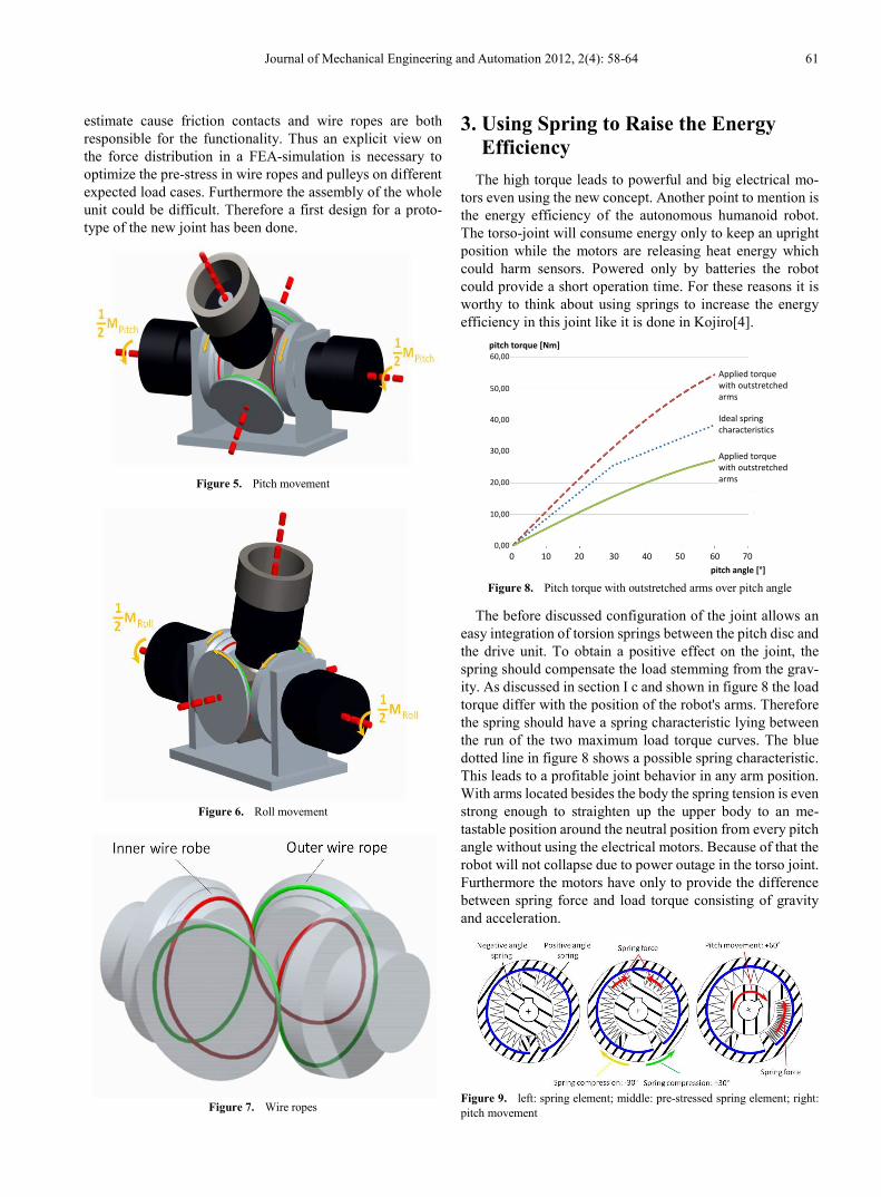
Figure 8. Pitch torque with outstretched arms over pitch angle
The before discussed configuration of the joint allows an easy integration of torsion springs between the pitch disc and the drive unit. To obtain a positive effect on the joint, the spring should compensate the load stemming from the grav-ity. As discussed in section I c and shown in figure 8 the load torque differ with the position of the robot's arms. Therefore the spring should have a spring characteristic lying between the run of the two maximum load torque curves. The blue dotted line in figure 8 shows a possible spring characteristic. This leads to a profitable joint behavior in any arm position. With arms located besides the body the spring tension is even strong enough to straighten up the upper body to an me-tastable position around the neutral position from every pitch angle without using the electrical motors. Because of that the robot will not collapse due to power outage in the torso joint. Furthermore the motors have only to provide the difference between spring force and load torque consisting of gravity and acceleration.
Figure 9. left: spring element; middle: pre-stressed spring element; right: pitch movement
60,00
50,00
40,00
30,00
20,00
10,00
0,000 10 20 30 40 50 60 70
pitch angle [°]
pitch torque [Nm]
Applied torquewith outstretchedarms
Ideal spring characteristics
Applied torquewith outstretchedarms

62 Christian Sander et al.: Design of a New Torso-Joint for the Humanoid Robot ARMAR
Bow springs can be used to obtain an adequate spring force. They have a nearly linear spring characteristic and are easy adaptable to changing load conditions. The superposed position requires a negative angle. Therefore two springs are needed because bow springs can usually only transmit pressure forces. So there is one for the positive angle dis-placement and one for the negative. Figure 9 left explains the design of the spring element.
The outer casing is firmly connected to the structure of the lower body. The inner part of the element transmits the tor-que resulting from the compressed springs into the pitch disc. The motor delivers the additional torque needed through the shaft in the middle of the spring elements. So motor and the spring element are in a parallel arrangement and the spring element works only supportive for the motions. Any com-pliant actuation could not be achieved with this system.
Before assembling the whole unit, the spring characteristic could be improved manually. By twisting the spring element around 30° the springs will be compressed and preloaded (see figure 9 middle). This leads to a superposition of the spring forces in an angle range of -30° to +30° and gives in this section a steeper spring characteristic like the blue dotted one in figure 8.
Integration of the load torque over the angle clarifies the energy saving potential of the spring element. Therefore a pitch motion from 0° to 60° (1.047[rad]) was analyzed and is shown in the following.
JmgdRE 49.31)sin(21047.1
0maxmax == ∫ ϕϕ (1)
Whereby the upper body mass was estimated to m=32.32 kg including batteries and computers. The maximal distance with outstretched arms Rmax between the joint and the gravity center is 39.74 cm. The gravitational constant g is 9.81 m/s2. The load resulting on one motor is divided by 2 because the two motors share it equally in a pitch motion.
With arms located besides the body the distance Rmin=19.8 cm between the center of gravity and center of rotation is much smaller. The energy needed from one motor without springs is in this case:
JmgdRE 69.15)sin(21047.1
0minmin == ∫ ϕϕ (2)
By using the spring elements a share of the energy can be saved in the springs. The spring stiffness was chosen to be exactly in the middle the two load curves and was calculated to c=24.5 Nm/rad. The spring stiffness in the range of 0° and 30° is doubled because the negative angle spring acts against the positive one (see figure 9). b=12.83 Nm results from the preloaded spring.
JbdcdcEspring 51.232047.1
0
541.0
0
=++= ∫∫ ϕϕϕϕ (3)
The difference between the saved energy and the load torque energy has to be delivered by the motors. This is for one motor to obtain the movement with outstretched arms:
JEEE springmotor 98,7max −=−= (4) It complies with only 25.34 % of the energy without
springs. The negative sign means that the resulting moments of the motors work in the same direction as the force of the compressed spring.
If the center of gravity is in its nearest position to the joint, the energy revealed from one motor has to be:
JEEE springmotor 71,7min =−= (5) It complies with 49.14 % of the energy without springs
and the motors have to work against the spring force. Figure 10 shows the torque needed by one motor to hold
the upper body in a specific pitch angle.
Figure 10. Pitch torque over pitch angle with spring support
The following table gives an overview of the absolute values of maximum torque reacting on the drive units caused by gravity during different motion.
Table 2. Requirements
Degree of Freedom Max. Torque on one motor[Nm] no springs with springs
Roll 12.8 4.7 Pitch 54.5 16.2
superposed Motion 57.5 25.4
It is necessary to take account of additional torque caused by acceleration of the upper body mass. There might be also losses due to friction between the spring and the casing which cannot be estimated for the time being. This should be a subject in further investigations. But it is obvious that with the use of the spring elements less performance is required from the motors. Hence we are able to use much smaller and lighter motors for the torso-joint.
4. FEA-Simulation In Order to calculate the stiffness and mechanical strength
of the new concept a Finite Element Analysis (FEA) was conducted. As the solver for the simulation, ABAQUS from Dassault Systemes was used. The FEA-simulation shows the distribution of the tension in the different parts. In addition, the rigidity of the system has to be calculated, because it is crucial for the implementation of this joint (in an arrange-ment of several joints in a series). A small backlash in the torso joint is propagated because the various connected links
15,00
10,00
5,00
0,00
-5,00
-10,00
-15,00
pitch torque [Nm]
-20,00
Applied torquewith outstretchedarms
Applied torquewith outstretchedarms
10 20 30 40 50 60 70
pitch angle [°]
Journal of Mechanical Engineering and Automation 2012, 2(4): 58-64 63
of the robot result in great position inaccuracies in the outer extremities. Furthermore the goal of creating a lightweight torso-joint makes it important to use lightweight aluminum alloys like e.g. AlMgZnCu1,5. In the simulation this fact should be considered.
Figure 11. left: FEM-Model with 4 discs and ropes; right: rope model
Figure 12. FEM-result (force of -1286 N in z, preload rope=450 N, prel-oad disc=660 N)
In order to reduce the computing time, the CAD model must be simplified while the fundamental behavior of the system should be modeled as accurate as possible. In fig-ure 11 (left) the finite element model (FEM) is illustrated. It consists of four discs, a shaft and eight ropes. Each disc is meshed with C3D10M elements. The pitch disc consists of 16872 elements and the roll-discs of 12079 elements. The element distribution at the contact surfaces is very fine and a Lagrange-Contact with μ=0:2 is chosen[9] to be able to analyze the contact pressure. Much of the force redirection takes place over the embracing ropes. These cables are supported by the frictional forces at the contact points be-tween the discs. The ropes are modeled, using two MPC pins, different translators, a wire and finally a structure element as shown in figure 11 (right). In the following table the influ-ence of the material on stiffness and weight of the discs is shown. Every rope is preloaded by 450 N and the discs are preloaded by 660 N which was the optimal result of a pa-rameter variation. A force of 1286 N, to simulate the weight of the upper body plus a safety factor, is applied to the bar in negative z-direction. The maximum displacement, compar-ing steel- and aluminum-alloys, divers only about 7,3 % although the weight differs about 250 %.
Moreover, the achievable stiffness with the high-strength
aluminum alloy AlZnMgCu1.5 is satisfying. So here, the use of aluminum alloy is preferred. In figure 12 the stress dis-tribution (v. Mises) is printed.
Table 3. Requirements
Material E-Modulus [GPa] Weight [g] Displacement
[mm] Al-Alloy 70 814 0,0151 Fe-Alloy 210 2056 -0,0140
Difference 1242 -0,0011
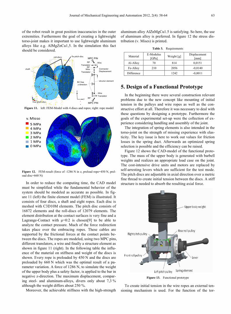
5. Design of a Functional Prototype In the beginning there were several construction relevant
problems due to the new concept like mounting of initial tension in the pulleys and wire ropes as well as the con-structive effort at all. Therefore it was necessary to deal with these questions by designing a prototype. Furthermore the goals of the experimental set-up were the collection of ex-perience considering handling and assembly of the joint.
The integration of spring elements is also intended in the torso-joint on the strength of missing experience with elas-ticity. The key issue is here to work out values for friction losses in the spring duct. Afterwards an optimized spring selection is possible and the efficiency can be raised.
Figure 12 shows the CAD-model of the functional proto-type. The mass of the upper body is generated with barbell weights and realizes an appropriate load case on the joint. The cost-intensive drive units and motors are replaced by self-arresting levers which are sufficient for the test mode. The pitch discs are adjustable in axial direction over a metric fine thread to create initial tension between the discs. A stiff structure is needed to absorb the resulting axial force.
Figure 13. Functional prototype
To create initial tension in the wire ropes an external ten-sioning mechanism is used. For the function of the tor-
fix pitch-disc
free pitch-disc
roll-discs
shaft
y
y
F

64 Christian Sander et al.: Design of a New Torso-Joint for the Humanoid Robot ARMAR
so-joint it is very important to ensure a centered position of the discs to each other. Therefore a centering rod is used and the contact areas of the parts have to be manufactured in small range of tolerance. This first dimensioning can be seen as groundwork for the application of the joint in the new generation of the humanoid robot ARMAR V.
The complete dimension of the joint is 196 mm in width, the height is 120 mm and the depth is 150 MM. The in sec-tion 1.3 mentioned design goals could not be achieved al-together. But the FEA-simulation shows great potential regarding to a much smaller Torso-Joint. This should be subject in a further design.
6. Conclusions During the design development several problems con-
cerning the feasibility could be revealed and solved. How-ever they are leading to complex design and additional parts like the external tension mechanism and the centering rod. Great effort has to be spent on the manufacturing process because a centered position of the parts is indispensable for the function. All this leads to a difficult but feasible assembly. Nevertheless this new concept offers numerous advantages. The parallel kinematic splits the high torque requirements on two motors which enables the use of smaller and lighter motors and gearboxes. Due to the discs additional space is available for the accommodation of the yaw-unit. The spring elements raise the energy efficiency remarkable on the joint. The additional effort and installation space is compensated by smaller motors.
The FEA-simulation has shown a great stiffness of the cumulative function of the cone discs’ friction contacts and wire ropes. Even smaller and more elastic ropes as well as smaller cone discs are possible in further developments to achieve a sufficient stiffness in the joint.
ACKNOWLEDGEMENTS The work presented in this article is funded by the
"Deutsche Forschungsgemeinschaft" (DFG) within the Collaborative Research Centre 588 "Humanoid Robots- Learning and Cooperating Multimodal Robots".
REFERENCES [1] Schaefer, C.: Entwurf eines anthropomorphen Roboterarms:
Kinematik,Arbeitsraumanalyse, Softwaremodellierung, Dis-sertation Fakultaet fuer Informatik, Universitaet Karlsruhe, 2000.
[2] Albers, A.; Brudniok, S.; Ottnad, J.; Sauter, C.; Sedchaicharn, K.: Upper Body of a new Humanoid Robot - the Design of ARMAR III, Humanoid Robots, 2006 6th IEEE-RAS Inter-national Conference on Humanoid Robots (Humanoids 2006), pp.308-313, 4-6 Dec. 2006
[3] Mizuuchi,I.; Yoshikai, T.; Sodeyama, Y.; Nakanishi, Y.; Miyadera, A.:Yamamoto, T.; Niemela, T.; Hayashi, M.; Urata, J.; Namiki, Y.; Nishino, T.; Inaba, M.: Development of Musculoskeletal Humanoid Kotaro, in the Proceedings of the 2007 IEEE-RAS International Conference on Humanoid Robots (Humanoids 2007), December 2007
[4] Mizuuchi, I.; Nakanishi, Y.; Sodeyama, Y.; Namiki, Y.; Nishino, T.; Muramatsu, N.; Urata, J.; Hongo, K.; Yoshikai, T.; Inaba, M.: An Advanced Musculoskeletal Humanoid Ko-jiro, in the Proceedings of the 2006 IEEE International Con-ference on Robotics and Automation Orlando, Florida, May 2006
[5] Lohmeier, S; Buschmann, T.; Ulbrich, H.: System Design and Control of Anthropomorphic Walking Robot LOLA. in Pro-ceedings of IEEE/ASME Transactions on Mechatronics, VOL. 14, NO. 6, DECEMBER 2009
[6] Tsagarakis, N. G.; Becchi, F.; Righetti, L.; Ijspeert, A.J.; Caldwell, D.G.: Lower Body Realization of the Baby Hu-manoid - ’iCub’, in the Proceedings of the 2007 IEEE/RSJ International Conference on Intelligent Robots and Systems, San Diego, CA, USA, November 2007
[7] Tellez, R.; Ferro, F.; Garcia, S.; Gomez, E.; Jorge, E.; Mora, D.; Pinyol, D.; Oliver, J.; Torres, O.; Velazquez, J.; Faconti, D.: Reem-B: An autonomous lightweight human-size hu-manoid robot, in the Proceedings of the 2008 IEEE-RAS In-ternational Conference on Humanoid Robots (Humanoids 2008), December 2008
[8] Kaneko, K.; Kanehiro, F.; Morisawa, M.; Miura, K.; Nakaoka, S.; Kajita, S.: Cybernetic human HRP-4C, Humanoid Robots, 2009. Humanoids 2009. 9th IEEE-RAS International Confe-rence on Humanoid Robots , vol., no., pp.7-14, 7-10 Dec. 2009
[9] Feldhusen, J.; Grote, H.: Dubbel - Taschenbuch fuer den Maschinenbau, Chapter B, Page 14, ISBN978-3-540-68191-5, Springer-Verlag Berlin Heidelberg, 2007