design of continuously reinforced concrete pavement with heat
TRANSCRIPT
Design of Continuously Reinforced Concrete Pavement with Heat Transfer System for a Bus
Terminal in Hamilton
Ludomir Uzarowski, Ph.D., P.Eng., Golder Associates Ltd., Whitby, Ontario
Imran Bashir, M.Sc., P.Eng., Golder Associates Ltd., Whitby, Ontario
Rabiah Rizvi, Co-Op Student, Golder Associates Ltd.. Whitby, Ontario
Paper prepared for presentation at the
Innovations in Pavement Design and Evaluation Session
of the 2010 Annual Conference of the Transportation Association of Canada
Halifax, Nova Scotia
Acknowledgements
The authors express their gratitude to Denis Thebeau from MTQ and Tim Smith from Concrete Association of Canada for their help with the CRCP design.

ABSTRACT MacNab Street Bus Terminal is located between Main Street and King Street in downtown Hamilton and is primarily used as a transit terminal. An existing underground concrete tunnel structure is located beneath portions of the road. The proposed pavement improvements include the reconstruction and widening of MacNab Street with a concrete pavement structure and the construction of two new concrete passenger platforms complete with canopies. Consideration was initially given to the reconstruction of MacNab Street using a jointed plain concrete pavement (JPCP). However, as a heat tracing system was designed for placement within the pavement, it was decided that the new structure should be a continuously reinforced concrete pavement (CRCP). This reduced the number of transverse contraction joints in the pavement from 40 to just 2. The concrete pavement was designed on a 50 mm thick insulation. The new pavement will be subjected to about 500 buses per day with the possibility of increasing to as many as 750 busses per day. The design traffic loading for a 20 year period is 26 million ESAL’s. There is very limited experience in Canada with the design of CRCP. There are a few CRCP pavements in Quebec and one in Alberta. The initial pavement design was carried out in accordance with the 1993 AASHTO Guide for the Design of Pavement Structures. The reinforcement in the CRCP on MacNab terminal was designed following the procedure developed by the Quebec Ministry of Transportation (MTQ). In order to accommodate longitudinal movements at the CRCP ends and to provide transition from CRCP to asphalt pavement, two terminal expansion joints were designed at both ends of the pavement. The influence of the heating pipes and allowable movement across transverse contraction joints was also considered in the design.

3
1.0 INTRODUCTION The MacNab Street Bus Terminal is located in downtown Hamilton, Ontario between Main Street and King Street. The existing road at the site is about 150 m in length and is a paved asphalt surface with three lanes in the northbound direction and two lanes in the southbound direction. The northbound and southbound lanes are divided by a concrete passenger platform. An underground concrete tunnel is located beneath sections of the road. Figure 1 shows the location of the McNab Street Site. The project involved the reconstruction and widening of MacNab Street using a concrete pavement structure with a heat tracing system imbedded in the concrete pavement.
Figure 1 Aerial view of the MacNab Street Bus Terminal site The road reconstruction of the section involves constructing two lanes in each direction with concrete curb and gutter on both sides. Two passenger platforms are to be constructed along the road; one in the centre dividing the northbound and southbound lanes and the second along the west end of the road along the northbound lane. Three concrete pavement alternatives, listed below, were initially considered for use on this project. Concrete base with precast concrete pavers placed on top Jointed plain concrete pavement (JPCP) Continuously reinforced concrete pavement (CRCP)

4
The first alternative was not considered in great detail and was rejected very early in the process. A heat tracing system needed to be imbedded into the pavement structure in order to melt snow and prevent any ice forming on the pavement surface during the winter months. The requirement for the installation of a heat tracing system eliminated the second alternative due to the requirement for a large number of joints in this type of concrete pavement. CRCP was considered the optimum solution for the pavement at this site. The CRCP was to be constructed on an insulating layer on extruded polystyrene that had a minimum thickness of 50 mm. This paper discusses the design process that was followed for the CRCP pavement for this project. 2.0 BACKGROUND CRCP has continuous longitudinal reinforcement and no transverse joints except construction joints or terminal joints necessitated by existing conditions at the site. CRCP does not eliminate the formation of transverse cracks in the concrete pavement but rather the purpose of the reinforcing steel in CRCP is to prevent the cracks from widening and to provide adequate load transfer as traffic moves across the cracks. The main distress mechanisms that are of concern in CRCP are transverse cracking, pumping, spalling, punchouts, and steel rupture [1]. The primary criteria indicating the performance of CRCP is the width of the transverse cracks; therefore, during design it has to be ensured that there is sufficient steel reinforcement in the pavement to hold the crack together. The main hindrance in using CRCP as a paving alternative is relatively high capital cost primarily due to the large amount of reinforcing steel used in this type of pavement [2]. However, based on life-cycle cost analysis, in some cases the present value of CRCP can be lower than that of JPCP; it is dependant on the amount of traffic to be carried. The Quebec Ministry of Transport (MTQ) found for one particular project that the life-cycle cost of CRCP was about 5.0 percent lower than that of JPCP based on a 50 year analysis period [3]. The reduction in life-cycle cost of CRCP is due to the fact that it requires little to no maintenance and this in turn also reduces user delay costs. According to a Federal Highway Administration Report Published in October 1998, CRCP has been used in at least 35 states and constitutes about 45,000 lane km of the road network in the United States. The use of CRCP in the United States started in the 1930’s; however, the technology started to be used more extensively in the 1960’s. In the state of Illinois, which has a similar climate to that of southern Ontario, about 1,600 km of CRCP has been constructed; these sections have performed extremely well in light of the traffic that they have carried compared to what they were designed for. Also, given the performance of their CRCP sections, Illinois continues to prefer CRCP for pavement sections experiencing very heavy truck traffic. In Europe CRCP has been used in France, Belgium, Netherlands, United Kingdom and Spain. [5] In Canada there is very limited experience with CRCP. In 1958, multiple CRCP sections with various designs were constructed on portions of the Trans-Canada Highway near Calgary, Alberta [5]. In Quebec two test sections of CRCP were constructed with the first being on Highway 13 North in Laval and the second on a section on Highway 40 East

5
[4]. The two test sections have been reported to have been performing satisfactorily in terms of crack, salt penetration, and smoothness. Some of the cracks were below the minimum allowable spacing; however, there were no signs that indicated that punchouts were imminent. The smoothness of the sections showed little to no deterioration 3 years after construction. Finally there was limited salt penetration in to the cracks indicating that the corrosion of the reinforcing steel would be less than what was initially estimated. Further research was proposed in 2006 by the MTQ to look at various aspects of the design of CRCP [2]. The MacNab Street Bus Terminal Project is the first CRCP project in Ontario and this paper details the design process that was followed. The terminal is currently under construction. 3.0 HEAT TRANSFER SYSTEM Heat transfer systems have been used in pavement applications for the purpose of snow melting in various countries including United States, Japan, Argentina, Canada and Switzerland. Besides that there is no longer a need for snow removal, further benefit includes increased safety for vehicles and pedestrians using the facility. The system involves circulating a solution of glycol through pipes that are imbedded in the pavement structure. It was decided that for this project a plastic piping system would be used since any metal pipes would likely corrode and significantly reduce the life of the heat transfer system. The plastic pipes are also light weight and significantly easier to handle. The glycol will also prevent the water from freezing in the pipes while it was not circulating. Portland cement concrete (PCC) was selected instead of asphalt concrete as the asphalt concrete would be placed at very high temperatures which would likely damage the plastic pipes imbedded in the pavement. Further, CRCP was the type of PCC pavement selected for this project to reduce the number of joints in the pavement. The expansion and contraction in JPCP can be significant and this can damage the plastic pipes that are imbedded in the pavement. It was also considered critical to protect the pipes from frost heaving; this was achieved by installing an insulation layer between the CRCP and the granular base. The insulation layer also reduced the heat loss to the layers below the CRCP which would significantly reduce the energy required for snow melting. It was considered essential that at the time of construction of the CRCP the piping system not be crushed or damaged. Therefore, it was recommended that the pipes should be aligned and beneath the longitudinal reinforcement. It was also recommended that the pipe design should take into account the movements that would take place at the terminal joints and potentially at the joints within the CRCP section.

6
4.0 PAVEMENT DESIGN This section of MacNab Street consists of two lanes in each, northbound and southbound, direction. Figure 2 shows the original asphalt pavement in the northbound direction looking from Main Street. Figure 3 shows a photograph taken from Main Street of the existing southbound lane. The passenger platform that divides the existing northbound and southbound lanes and will divide the reconstructed lanes is also shown in Figures 2 and 3. CRCP was the recommended pavement types for the terminal and a heating system was to be imbedded in the CRCP. The CRCP was designed on top of an extruded polystyrene insulation layer that has a thickness of 50 mm. The two transverse joints would be in the locations of existing joints in the passenger platforms that ran along the side of the roadway. The reduced number of transverse joints was beneficial for the installation of the piping of the heat transfer system. Two terminal joints were also designed at the ends of the CRCP section.
Figure 2 Existing northbound lane looking from Main Street

7
Figure 3 Existing southbound lane looking from Main Street
4.1 Traffic Analysis The project section serves as a transit bus terminal and is expected to be subjected to about 500 busses per day and that number could increase to as much as 750 busses per day over the design life of the CRCP. The transit busses using the section are 12 m long and have a load of 7,000 kg on the front axle and 13,000 kg on the rear axle. In order to determine the design ESALs for this section a truck equivalency factor of 4.1 was assumed based on the research done by others [6]. A traffic growth rate of 1.0 percent was also used for the calculation. The design Equivalent Single Axle Loads (ESALs) calculated for a 30 design life years was 26,000,000. 4.2 Pavement Thickness Design The pavement thickness design of the CRCP was carried out in accordance with the 1993 AASHTO Guide for the Design of Pavement Structures [7] and the Ontario Ministry of Transportation MI-183 Publication entitled “Adaptation and Verification of the AASHTO Pavement Design for Ontario Condition” [8]. Table 1 presents the parameters that were used for the pavement design. In order to determine the effective modulus of subgrade reaction (k), a subgrade resilient modulus of 27 MPa and a base elastic modulus of 250 MPa were assumed based on a geotechnical investigation. The native subgrade soils found during the geotechnical investigations included deposits of sand, silty sand and gravel which was underlain by a silty clay till deposit.

8
Table 1 Parameters used for pavement thickness design Pavement Design Parameter Value
Concrete Modulus of Rupture @ 28 days (MPa) 5.0 Concrete Modulus of Elasticity (MPa) 30,000 Estimated Effective Modulus of Subgrade Reaction – k (MPa/m) 85 Design Period (Years) 30 Reliability Level (%) 90 Overall Standard Deviation 0.35 Load Transfer Coefficient 2.8 Estimated Design ESALs 26,000,000
The designed thickness of the CRCP layer was 250 mm. The CRCP layer will be constructed on top of a 50 mm thick insulation layer placed on a 300 mm layer of granular base. The base course should be constructed on top of a prepared and approved subgrade. The assumed flexural strength of the concrete for the CRCP was 5MPa and the compressive strength was 35 MPa at 28 days with C2 exposure. The concrete should have a nominal maximum aggregate size of 37.5 mm. The surface of the CRCP should be tined in order to provide adequate frictional characteristics to the pavement. 4.3 Reinforcing Steel Design and Placement The percentage and spacing of longitudinal and transverse reinforcing steel that would be required in the CRCP was intially designed using AASHTO 1993 [7] and then updated using a method that was developed by the Quebec Ministry of Transportation (MTQ). For the longitudinal reinforcement 20 M (#6) bars were recommended and for the transverse reinforcement 15 M (#5) bars were recommended. Table 2 shows the parameters that were used in the design of the longitudinal reinforcement. A lane width of 3.75 m was used in the design to determine the spacing of the transverse bars.
Table 2 Parameter used for longitudinal reinforcement design Design Parameter Value
28-day Concrete Indirect Tensile Strength (kPa) 4,300 Concrete Shrinkage at 28 days (mm/mm) 0.00028
Thermal Coefficient of Concrete (10-6 mm/mm/°C) 6.8
Thermal Coefficient of Reinforcing Steel (10-6 mm/mm/°C) 11.5 Design Temperature Drop (°C) 20 Tensile Stress Due to Wheel Load (kPa) 1600 Allowable Steel Stress (MPa) 310 Allowable Crack Width 0.5 Bar Diameter (mm) 19.5
9
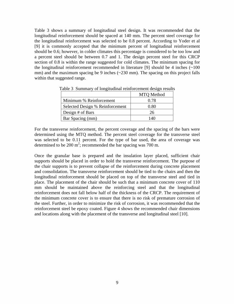
Table 3 shows a summary of longitudinal steel design. It was recommended that the longitudinal reinforcement should be spaced at 140 mm. The percent steel coverage for the longitudinal reinforcement was selected to be 0.8 percent. According to Yoder et al [9] it is commonly accepted that the minimum percent of longitudinal reinforcement should be 0.6; however, in colder climates this percentage is considered to be too low and a percent steel should be between 0.7 and 1. The design percent steel for this CRCP section of 0.8 is within the range suggested for cold climates. The minimum spacing for the longitudinal reinforcement recommended in literature [9] should be 4 inches (~100 mm) and the maximum spacing be 9 inches (~230 mm). The spacing on this project falls within that suggested range.
Table 3 Summary of longitudinal reinforcement design results MTQ Method Minimum % Reinforcement 0.78 Selected Design % Reinforcement 0.80 Design # of Bars 26 Bar Spacing (mm) 140
For the transverse reinforcement, the percent coverage and the spacing of the bars were determined using the MTQ method. The percent steel coverage for the transverse steel was selected to be 0.11 percent. For the type of bar used, the area of coverage was determined to be 200 m2; recommended the bar spacing was 700 m. Once the granular base is prepared and the insulation layer placed, sufficient chair supports should be placed in order to hold the transverse reinforcement. The purpose of the chair supports is to prevent collapse of the reinforcement during concrete placement and consolidation. The transverse reinforcement should be tied to the chairs and then the longitudinal reinforcement should be placed on top of the transverse steel and tied in place. The placement of the chair should be such that a minimum concrete cover of 110 mm should be maintained above the reinforcing steel and that the longitudinal reinforcement does not fall below half of the thickness of the CRCP. The requirement of the minimum concrete cover is to ensure that there is no risk of premature corrosion of the steel. Further, in order to minimize the risk of corrosion, it was recommended that the reinforcement steel be epoxy coated. Figure 4 shows the recommended chair dimensions and locations along with the placement of the transverse and longitudinal steel [10].

10
Figure 4 Chair support dimension and location [10]
In order to maintain continuity of the two longitudinal reinforcement bars it was recommended that lap splices should be used. The length of the splices should be 700 mm and the splices should be staggered across the pavement in order to avoid localized build-up of stresses and strains. The minimum distance between the lap splices should be 1.2 m and no more than one third of the bars should terminate in the same transverse plane. If the two lanes in each direction are constructed at the same time it was recommended that the transverse reinforcement should extend across the width of both lanes. The longitudinal joint should be formed by sawing to a depth of one-third the CRCP thickness along the lane delineation. However, if the lanes are not constructed at the same time, then adjacent lanes should be tied together using deformed tie bars in order to prevent lane separation. It was suggested that the tie bars be 15 M bars that are 760 mm long. They should be placed in the middle of the transverse reinforcement at 700 mm spacing. Further, it was suggested that he CRCP should be tied to the concrete curb and gutter using the same dimension tie bars at the same spacing as for longitudinal joints. 4.4 Terminal Joint Design In order to accommodate movement of the CRCP at both ends of the section and to provide transition from the CRCP to the asphalt concrete pavement, it was recommended that two expansion joints be constructed at the ends of the CRCP section. Since the
11
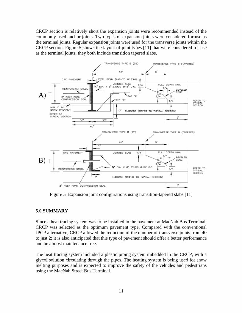
CRCP section is relatively short the expansion joints were recommended instead of the commonly used anchor joints. Two types of expansion joints were considered for use as the terminal joints. Regular expansion joints were used for the transverse joints within the CRCP section. Figure 5 shows the layout of joint types [11] that were considered for use as the terminal joints; they both include transition tapered slabs.
Figure 5 Expansion joint configurations using transition-tapered slabs [11]
5.0 SUMMARY Since a heat tracing system was to be installed in the pavement at MacNab Bus Terminal, CRCP was selected as the optimum pavement type. Compared with the conventional JPCP alternative, CRCP allowed the reduction of the number of transverse joints from 40 to just 2; it is also anticipated that this type of pavement should offer a better performance and be almost maintenance free. The heat tracing system included a plastic piping system imbedded in the CRCP, with a glycol solution circulating through the pipes. The heating system is being used for snow melting purposes and is expected to improve the safety of the vehicles and pedestrians using the MacNab Street Bus Terminal.
A)
B)

12
The CRCP thickness and reinforcement was initially designed using the AASHTO 1993 design guide. The reinforcement design was updated using the MTQ method. The design pavement structure consisted of a 250 mm thick CRCP constructed on top of a 50 mm thick polystyrene insultation layer and a 300 mm thick granular base. The longitudinal reinforcement design consisted of 20 M bars providing 0.8 percent steel coverage and spaced at 140 mm intervals. The transverse reinforcement design consisted of 15 M bars providing 0.11 percent steel coverage and spaced at 700 mm intervals. Adequate chair supports should be used in order to prevent the collapse of the transverse and longitudinal reinforcement. Two types of expansion joints were considered for both ends of CRCP instead of anchor. There is very limited experience with using CRCP in Canada and the MacNab Street Bus Terminal project will be the first CRCP installation in Ontario. In addition, the use of a heat tracing system within the CRCP makes this project unique. REFERENCES 1. Stock, A. F., “Concrete Pavement”, Elsevier Applied Science, Crown House, Linton
Road, Barking, Essex, England, 1988.
2. Thebeau, D., Davidson, F. “First Experience with Continuously Reinforced Concrete Pavement (CRCP) in Canada”, Quebec Ministry of Transport, Quebec, Canada.
3. Hall, K., et al., “Long Life Concrete Pavements in Europe and Canada”, FHWA-PL-
07-027, Federal Highway Administration (FHWA), August 2007.
4. Thebeau, D., “Continuously Reinforced Concrete Pavements at Transport Quebec”, Presentation at the 2004 Annual Conference of the Transportation Association of Canada, Quebec City, September 2004.
5. Tayabji, S. D., et. al., “Performance of Continuously Reinforced Concrete Pavements:
Volume I – Summary of Practice and Annotated Bibliography”, FHWA-RD-94-178, Federal Highway Administration (FHWA), October 1998.
6. Burlie, R., Emery, J., “Evaluation of Urban Asphalt Concrete Rutting”, Proceedings
of the Annual Conference of the Canadian Technical Asphalt Association, Vol 42, 1997.
7. AASHTO, “AASHTO Guide for Design of Pavement Structures”, American
Association of State Highway and Transportation Officials, Washington, D.C., 1993.
8. MTO, “Adaptation and Verification of AASHTO Pavement Design Guide for Ontario Conditions”, MI-183, Ontario Ministry of Transportation, 2001.
9. Yoder, E. J., Witczak, M. W., “Principles of Pavement Design”, Second Edition, John
Wiley & Sons Inc., 111 River Street, Hoboken, New Jersey, 1975.

13
10. FHWA, “Technical Advisory: Continuously Reinforced Concrete Pavement”, T
5080.14, Federal Highway Administration (FHWA), June 5, 1990, http://www.fhwa .dot.gov/pavement/t508014.cfm.
11. Jung, Y. S. & Zollinger, D. G., “Design and Construction Transition Guidelines For
Concrete Pavement”, FHWA/TX-07/0-5320-P3, Federal Highway Administration (FHWA), March 2007.