design of mechanically actuated aerodynamic braking system ... · racing formula student car to...
TRANSCRIPT

ARTICLE OF PROFESSIONAL INTEREST
Design of Mechanically Actuated Aerodynamic Braking Systemon a Formula Student Race Car
Vivek Muralidharan1 • Abhijith Balakrishnan1 • Vinit Ketan Vardhan1 •
Nikita Meena1 • Y. Suresh Kumar1
Received: 20 March 2015 / Accepted: 23 March 2017 / Published online: 9 May 2017
� The Institution of Engineers (India) 2017
Abstract Every second in a racing competition counts the
performance of a team against the other. Many innovative
and sophisticated techniques are being employed to over-
come loses in time and add to the performance of the
vehicle. Especially in a car racing challenge there is more
freedom to install these innovative systems to empower the
car to maximum efficiency due to availability of more
space. At the global spectrum there are few events which
encourage such innovations. Formula Student Racing
competitions are one of the global events organized by the
Society of Automotive Engineers of different countries
which gives opportunity to university students to build and
race formula style cars. Like any other racing competitions
in this high octane event having an inch over their oppo-
nents is always an advantage. Not just better acceleration
and high velocities but also good deceleration is required to
excel in the competition. Aerodynamic braking system is
utilizing the aerodynamic drag force to create high decel-
eration. This mechanism can be installed on any car with
spoilers with minimum modification. Being a student event
great amount of care needs to be given to the safety con-
cerns of the driver.
Keywords Aerodynamic wings � Aerodynamic braking �Airfoil � Downforce � Drag � Formula student racing
Introduction
The Society of Automotive Engineers (SAE) in different
countries organize the formula student racing events gov-
erned by common rules and regulations set by SAE Inter-
national. This event is tailor-made for the university
students to design and build a formula style race car and
compete with their peers. It gives liberty to the student
teams to innovate mechanisms for better performance of
the vehicle under certain terms and conditions. Being a
student competition a lot of care has been given to safety of
the students, thereby having strict rules on designing and
manufacturing aspects of the car. Therefore any modifi-
cations on the car should abide by the stringent terms of the
rules [1].
Like any racing event, a student racing event also has
the thrill and intensity of competition. Minimal lap timings
are the concern of all the participating teams. Along with
good acceleration and high velocity, a good deceleration is
an important parameter which decides the performance of
the vehicle. A good amount of deceleration is required
especially while maneuvering sharp corners [2]. Besides,
the Formula Student racing event is classified into static
events and dynamic events. In order to qualify to the
dynamic events every team must clear the technical
inspection which includes the brake test [3] wherein every
car should brake in a straight line between two marked
lines on the track. It can be accounted that better deceler-
ation is required to execute smooth cornering and qualify
the brake test. In order to increase the braking ability of the
car, the drag created while steering can be utilized. The
aerodynamic wings also known as the spoilers can be
modified to capture the drag force created due to the
motion of the vehicle and thereby contribute to braking.
This paper is based on the work done over the NITK
& Vivek Muralidharan
1 Department of Mechanical Engineering, National Institute of
Technology Karnataka, Surathkal, Mangalore 575025,
Karnataka, India
123
J. Inst. Eng. India Ser. C (April 2018) 99(2):247–253
https://doi.org/10.1007/s40032-017-0354-1

Racing Formula Student Car to capture the drag force by
changing the angle of attack of the rear airfoil while
braking. On application of brakes, the aerodynamic wings
present at the rear are adjusted to corresponding angle of
attack where the drag created is maximum. A study has
been done to find the amount of braking force at different
angle of attack at different velocities.
Maximum Coefficient of Drag Condition
The research [4, 5] infers that the coefficient of drag of any
airfoil keeps increasing till angle of attack is 90�. In the
same manner the rear wing for team NITK Racing as
discussed [6] is optimized with a mechanism to alter the
angle of attack of the top blade at the rear to cause more
drag force while braking.
It is not always possible to achieve the maximum drag
condition with the proposed mechanism due to the limited
space for accommodating the movable links. As explained
the flat plate theory [5] the coefficient of drag (CD) is a
function of sine of the angle of attack (a) as in Eq. (1).
CD ¼ 2 sin2 a ð1Þ
where a can vary between 30� and 80�. In such cases even
before the airfoil is turned to 90� it should provide suffi-
cient drag force.
Based on Timmer’s conclusion [5] maximum coefficient
of drag can be approximated to a linear function of the
leading edge thickness as in Eq. (2).
CD;max ¼ ð1:994� 5:4375Þy=c ð2Þ
where y is the airfoil thickness measured at the leading
edge when x/c is 0.0125, x is the distance from the leading
edge along the chord line and c is the chord length. For the
Selig 1223 [7] airfoil the value of y/c is 0.04846. Hence the
maximum possible theoretical coefficient of drag is 1.730.
Drag on Multiple Airfoil System
Coefficient of Drag of S1223 Airfoil
The aerodynamic braking system at the rear comprises of
two blade staggered arrangement. The bottom blade is
stationary at a fixed inclination of 13� at which maximum
downforce is generated. This is connected the chassis for
transmitting the aerodynamic forces generated. The top
blade has the freedom to rotate about the pivot axis. The
Selig 1223 is an unsymmetrical deep cambered airfoil,
because of which the assumed aerodynamic center at 25%
chord is located outside the airfoil cross-section. The pivot
point is designed such that it lies within the airfoil cross
section nearer to the aerodynamic center. The major reason
for proximity of pivot point to the aerodynamic center is
that the aerodynamic lift and drag force and moment are
transferred to the structure effectively. Besides, not much
strain is generated on the body of the blades due to mini-
mum load transfer.
As explained [8] through Eq. (3) the net coefficient of
drag is the sum of all coefficient of drags due to individual
airfoils to that of the drag created due to interference of the
two airfoils.
CD1;2 ¼ CD1 þ CD2 þ CD interference ð3Þ
For orientation of top blade at 90�, the drag created is
1.730. At 13� inclination the bottom blade produces CD of
0.045. Therefore the staggered system must produce more
than the sum of individual coefficient of drag as in Eq. (4)
CD; staggeredwing �CD top þ CDbottom ð4Þ
The value of CD; staggered wing thus obtained shall be
greater than 1.775. For an ideal S1223 winged structure
such high value of coefficient of drag could have been
possible. Alterations to the design of the airfoil change the
coefficient of drag significantly.
Coefficient of Drag of Modified Airfoil Structure
Due to the rule specification of Formula Student racing [1]
it is mandatory to use a modified structure with 1.5 mm
radius of curvature at the tail end therefore the sharp tail
end needs to be shred as in Figs. 1, 2 Because of such
modification in the airfoil profile, it does not generate the
exact amount of drag force created by a normal S1223
airfoil.
The modified airfoil structure is not a standard structure
hence CFD analysis is the primary method to calculate the
value of coefficient of drag. The angle of attack of thetop
blade is varied from the maximum lift condition of 13�angle of attack as in Fig. 3 to sequential increase in angle of
attack varying from 17�, 25�, 40�, 60� to finally 90� as
shown in Figs. 4, 5, 6, 7, 8, respectively.
Fig. 1 Tail end (rear) up to the desired dimension [6]
248 J. Inst. Eng. India Ser. C (April 2018) 99(2):247–253
123
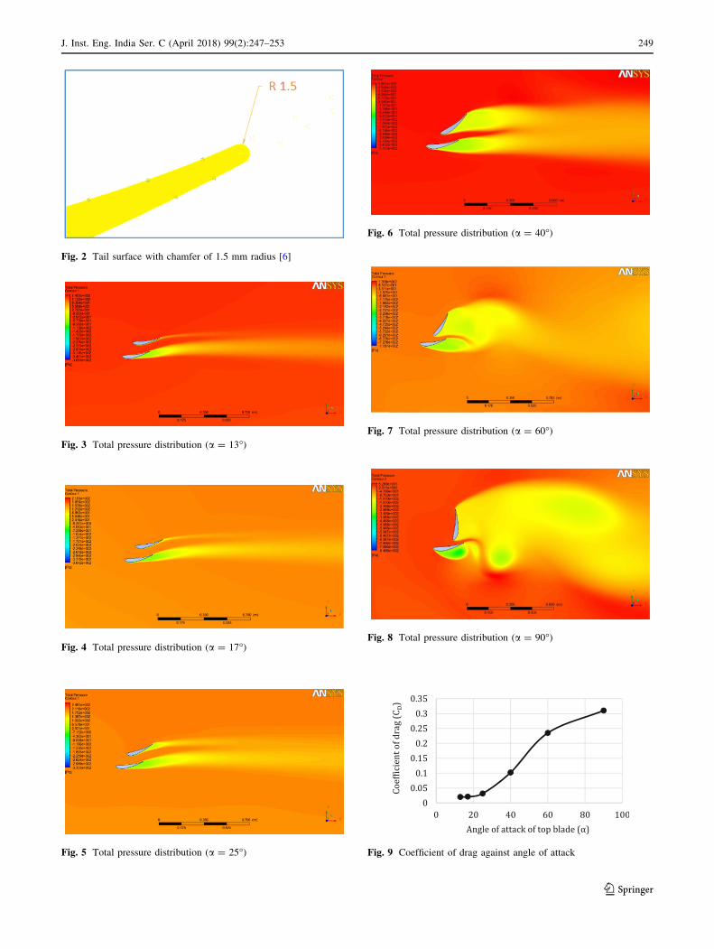
Fig. 2 Tail surface with chamfer of 1.5 mm radius [6]
Fig. 3 Total pressure distribution (a = 13�)
Fig. 4 Total pressure distribution (a = 17�)
Fig. 5 Total pressure distribution (a = 25�)
Fig. 6 Total pressure distribution (a = 40�)
Fig. 7 Total pressure distribution (a = 60�)
Fig. 8 Total pressure distribution (a = 90�)
0
0.05
0.1
0.15
0.2
0.25
0.3
0.35
Co
ef�
icie
nt
of
dra
g (
CD)
Fig. 9 Coefficient of drag against angle of attack
J. Inst. Eng. India Ser. C (April 2018) 99(2):247–253 249
123
For the modified Selig 1223 with shredded tail end, the
coefficient of drag against angle of attack was calculated
through the computational analysis as in Fig. 9.
As [9] the most frequently attained velocity of 50 kmph
is assumed as the base for calculating the flow character-
istics and to solve the coefficient of drag in ANSYS Fluent.
The values are then extrapolated for different velocities and
different angles of attack through the drag equation as in
Eq. (5)
Drag ¼ 1
2CDqAv
2 ð5Þ
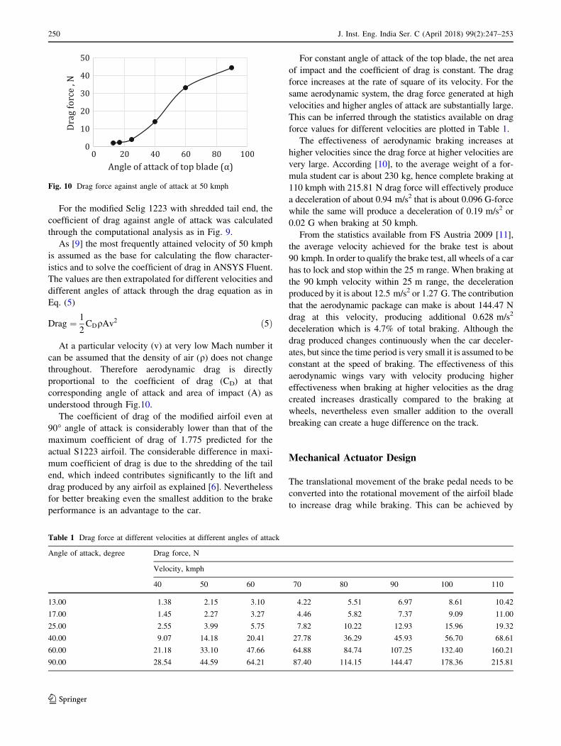
At a particular velocity (v) at very low Mach number it
can be assumed that the density of air (q) does not changethroughout. Therefore aerodynamic drag is directly
proportional to the coefficient of drag (CD) at that
corresponding angle of attack and area of impact (A) as
understood through Fig.10.
The coefficient of drag of the modified airfoil even at
90� angle of attack is considerably lower than that of the
maximum coefficient of drag of 1.775 predicted for the
actual S1223 airfoil. The considerable difference in maxi-
mum coefficient of drag is due to the shredding of the tail
end, which indeed contributes significantly to the lift and
drag produced by any airfoil as explained [6]. Nevertheless
for better breaking even the smallest addition to the brake
performance is an advantage to the car.
For constant angle of attack of the top blade, the net area
of impact and the coefficient of drag is constant. The drag
force increases at the rate of square of its velocity. For the
same aerodynamic system, the drag force generated at high
velocities and higher angles of attack are substantially large.
This can be inferred through the statistics available on drag
force values for different velocities are plotted in Table 1.
The effectiveness of aerodynamic braking increases at
higher velocities since the drag force at higher velocities are
very large. According [10], to the average weight of a for-
mula student car is about 230 kg, hence complete braking at
110 kmph with 215.81 N drag force will effectively produce
a deceleration of about 0.94 m/s2 that is about 0.096 G-force
while the same will produce a deceleration of 0.19 m/s2 or
0.02 G when braking at 50 kmph.
From the statistics available from FS Austria 2009 [11],
the average velocity achieved for the brake test is about
90 kmph. In order to qualify the brake test, all wheels of a car
has to lock and stop within the 25 m range. When braking at
the 90 kmph velocity within 25 m range, the deceleration
produced by it is about 12.5 m/s2 or 1.27 G. The contribution
that the aerodynamic package can make is about 144.47 N
drag at this velocity, producing additional 0.628 m/s2
deceleration which is 4.7% of total braking. Although the
drag produced changes continuously when the car deceler-
ates, but since the time period is very small it is assumed to be
constant at the speed of braking. The effectiveness of this
aerodynamic wings vary with velocity producing higher
effectiveness when braking at higher velocities as the drag
created increases drastically compared to the braking at
wheels, nevertheless even smaller addition to the overall
breaking can create a huge difference on the track.
Mechanical Actuator Design
The translational movement of the brake pedal needs to be
converted into the rotational movement of the airfoil blade
to increase drag while braking. This can be achieved by
Fig. 10 Drag force against angle of attack at 50 kmph
Table 1 Drag force at different velocities at different angles of attack
Angle of attack, degree Drag force, N
Velocity, kmph
40 50 60 70 80 90 100 110
13.00 1.38 2.15 3.10 4.22 5.51 6.97 8.61 10.42
17.00 1.45 2.27 3.27 4.46 5.82 7.37 9.09 11.00
25.00 2.55 3.99 5.75 7.82 10.22 12.93 15.96 19.32
40.00 9.07 14.18 20.41 27.78 36.29 45.93 56.70 68.61
60.00 21.18 33.10 47.66 64.88 84.74 107.25 132.40 160.21
90.00 28.54 44.59 64.21 87.40 114.15 144.47 178.36 215.81
250 J. Inst. Eng. India Ser. C (April 2018) 99(2):247–253
123

electronic means which can sense the pedal movement and
use this as the input for the servo controlled motors which
alter the angle of attack of the top blade [12]. The method
however precise, is sophisticated. Program to run the servo
needs to make the arrangements for the actuation of the
blade, also a continuous power supply is needed to actuate.
The mechanical method of actuation is much simpler and
economic. It converts the brake pedal travel to the rota-
tional motion at the hinge through tension cable.
The cable is attached to the fixed end as shown in
Fig. 11, when the driver applies the brake, the brake pedal
travel is transmitted by the cables to actuate the link
through the fixed end. The roller forces the change in angle
of attack of the top blade corresponding to the travel to
reach a final braking state with maximum drag as described
in Fig. 12. The link and the rolling contact together indeed
acts as a cam mechanism for a shorter stroke as explained
[13]. Instead of directly attaching the cable to the top blade
provision has been made to make a secondary mechanism
that actuates. The main purpose of this is that the load is
transferred through a line contact than a point contact in
direct attachment hence ensuring that the aerodynamic
blades are not damaged during the actuation. It is always
easier, economic and feasible to replace the other compo-
nents than the wings. The pivot point on the link can be
moved depending on the relation between input travel to
the output rotation required. The length of the link on either
side of the pivot point can be varied depending on torque
requirements as well as alter the amount of rotation
required.
As per observations from the NITK racing car, it is
determined that the brake pedal has a 2.4 cm travel at the
proposed mounting point. The upper wing is required to
angularly displace by 77� about its pivot corresponding to
this travel. The cable transmits the same travel at the brake
pedal to the point of attachment on the link. As per
geometry, the point of attachment of the cable to the link
from the pivot was calculated as 1.927 cm. Allowing for
cable play and other factors, a length of 2 cm from the
pivot was finalized.
Mechanical Actuator Setup
The mechanical actuator is manufactured using nylon
considering the force acting on it [14]. Most of the drag
force is carried by the endplates of the aerodynamic wing
along its hinge near to its aerodynamic center to the
wheels. Considering only the remaining force which acts
on the setup, nylon was chosen for its lightness and
machinability [15]. The setup was mounted at the center of
the bottom blade of the rear aerodynamic wing and high
tension cable was connected between the brake setup and
the brake pedal such that the brake travel can be trans-
mitted till the setup. In case of any errors induced to the
travel, the mounting point on the brake pedal may be
suitably varied to account for the same. Stainless steel link
is used to create play on the setup. Round rubber bob is
placed on top of the link to create a rolling contact during
its motion (Figs. 13, 14, 15, 16, 17).
Scope for Future
In this designed mechanism, the cable and the link are
directly coupled hence it is a linear function of brake pedal
travel to the rotation of the blade. Further analysis can be
done to optimise the function of brake travel to the required
output rotation. The function can be altered by changing
the dimension and orientation of the secondary members
that include the fixed end, link, pivot point and rolling
contact. Besides multiple links and other components can
Fig. 11 Actuator position when brakes disengaged
Fig. 12 Actuator position when brakes engaged
J. Inst. Eng. India Ser. C (April 2018) 99(2):247–253 251
123

be added to modify the existing relation between brake
pedal travel and change in angle of attack of the blades.
Thorough experiments which include wind tunnel testing
and on-track data acquisition, may be performed on the
aerodynamic package to validate the results. Although not
precise, driver feedback may be obtained from professional
test drivers.
Inference
The drag force at various angles of attack at different
velocities has been optimized for the modified S1223 air-
foil. Moreover, a linear actuation mechanism is designed to
transmit the brake pedal travel during braking to vary the
angle of attack of the top rear aerodynamic blade to a
maximum of 90� angle of attack to achieve maximum
braking.
Acknowledgements The authors are grateful to the faculty advisor of
team NITK Racing for his immense support to the team throughout.
Faculty and staff members of the Department of Mechanical Engi-
neering at NITK Surathkal, India provided great support to the
authors in technical and managerial assistance. Gratitude to the entire
team of NITK racing for their assistance while manufacturing. The
Fig. 13 Setup when brakes disengaged
Fig. 14 Setup when brakes engaged
Fig. 15 Actual view of rear wings when brakes disengaged
Fig. 16 Actual view of rear wings when brakes engaged
Fig. 17 Actual car with aerodynamic wings installed
252 J. Inst. Eng. India Ser. C (April 2018) 99(2):247–253
123

authors are thankful to fellow project mates for their worthy contri-
bution to this project. Sincere thanks to software providers, ANSYS
and CREO.
References
1. SAE International: Formula SAE Rules, http://students.sae.org/
cds/formulaseries/rules/2014_fsae_rules.pdf. Accessed 04 July
2014
2. B. Beckman, No bucks racing club: the physics of racing, part 5:
introduction to the racing Linehttp://www.esbconsult.com.au/
ogden/locust/phors/phors05.htm (1991). Accessed 27 Feb 2015
3. Institution of Mechanical Engineers (IMechE), UK, Formula
Student, The Challenge, http://events.imeche.org/formula-
student/about-us/thechallenge. Accessed 15 Aug 2014
4. J.L. Tangler, J.D. Kocurek, Wind turbine post-stall airfoil per-
formance characteristics guidelines for blade-element momentum
methods, 43rd AIAA Aerospace Sciences Meeting and Exhibit,
10–13, 2005
5. W.A. Timmer, Aerodynamic characteristics of wind turbine blade
airfoils at high angles-of-attack. 3rd EWEA Conference-Torque
(2010): The Science of making Torque from Wind, Heraklion,
Crete, Greece, 28–30 June 2010. European Wind Energy Asso-
ciation, 2010
6. V. Muralidharan, A. Balakrishnan, S. Kumar, Design optimiza-
tion of front and rear aerodynamic wings of a high performance
race car with modified airfoil structure, ICNTE, IEEE (2015).
doi:10.1109/ICNTE.2015.7029904
7. Airfoil Tools: Selig S1223 high lift low Reynolds number airfoil
http://airfoiltools.com/airfoil/details?airfoil=s1223-il (2014).
Accessed 14 Aug 2014
8. Pilotfriend, Fixed wing flight training: aerodynamics of drag,
http://www.pilotfriend.com/training/flight_training/aero/drag.htm
(2008). Accessed 13 Jan 2015
9. S. Wordley, S. Saunders, Aerodynamics for formula SAE: initial
design and performance prediction, SAE Technical Paper Series,
2006-01-0806, SAE International, 2005
10. Formula Society of Automotive Engineers, http://en.
wikipedia.org/wiki/Formula_SAE (2015). Accessed 18 Jan 2015
11. Braking Performance at Formula Student Competition,
http://www.fsae.com/forums/showthread.php?894-Average-100-
0-kph-braking-performance (2009). Accessed 25 Sept 2014
12. N. Balakrishnan, M. Alnouri, M. Heiranian, W. Koos, Design of a
front aerodynamic package, University of Manitoba, Canada
unpublished (2011)
13. Y. Zhang, S. Finger, S. Behrens, Introduction to Mechanisms,
Rapid Design through Virtual and Physical Prototyping,
https://www.cs.cmu.edu/*rapidproto/mechanisms/chpt6.html,
2010. Accessed 2 Nov 2015
14. M.W. Hyer, Stress Analysis of Fiber-Reinforced Composite
Materials, vol. 32 (DEStech Publications Inc, 2009)
15. PEP connecticut plastics: basics of plastic selection for machining,
http://www.pepctplastics.com/resources/plastic-part-design-guide/
basics-of-plastic-selection-for-machining/. Accessed 6 May 2015
J. Inst. Eng. India Ser. C (April 2018) 99(2):247–253 253
123