design of piles – german practice...issmge - etc 3 international symposium on design of piles in...
TRANSCRIPT

ISSMGE - ETC 3 International Symposium on Design of Piles in Europe Leuven Belgium 28 amp 29 April 2016
ltPrincipal Authorgt - ltTitlegt 135
Design of piles ndash German practice
Christian Moormann University of Stuttgart Institute for Geotechnical Engineering Germany
christianmoormannigsuni-stuttgartde christianmoormannmoormann-geotechnikde
ABSTRACT Germany has a long tradition of standardization with regard to the execution and design of pile foundations and other pile systems With the introduction of Eurocode 7 the principle of partial safety factor approach have replaced the global safety factor approach so far used for pile design as well as for other geotechnical design since many decades In consequence the existing standards and recommend-ations were revised and adapted to the new European regulations After a transition period with German codes adapted to the partial safety factor approach Eurocode 7-1 in combination with the National Annex and with DIN 10542010-12 including national supplementary rules to EC7-1 ndash all three together called acuteGerman Handbook EC 7 - Part 1acute are the basis for geotechnical design and as well for execution and design of pile foundations in Germany they are implemented as binding building regulations since 2012 Additional guidance for pile design and execution is provided by the acuteRecommendations on Piling (EA-Pfaumlhle)acute which were elaborated by the German Piling Committee These recommendations firstly published in 2007 are now well-established as best practice regulations and provide comprehensive support for all aspects of pile design covering also specific issues like negative skin friction group effects cyclic and dynamic loading etc This combination of standards and recommendations reflects also the German basic understanding that standards should focus on the principles of design and safety concepts whereas recommendations might provide more detailed support for engineering practice eg with different calculation methods background information continuative literature etc In this context the acuteEA-Pfaumlhleacute offers a specific approach to design axially loaded piles whereby this approach used as standard method bases on the empirical evaluation of comprehensive databases with pile load test results Due to the geological diversity in the subsurface of Germany the soil and rock conditions vary in a wide field and therefore a wide spectrum of pile types is used in Germany comprising nearly all kinds of bored piles displacement piles and micro piles
1 REGIONAL GEOLOGY
11 Geological overview
The geology of Germany is heavily influenced by several phases of orogeny in the Paleozoic and the Cenozoic by sedimentation in shelf seas and epicontinental seas and on plains in the Permian and Mesozoic as well as by the Quaternary glaciations The Geological sketch map of Germany (Figure 1) reflects the amazing diversity in the subsurface of Germany It is the result of many for hundreds of millions years ongoing processes that have shaped the geological underground in this part of Central Europe sedimentation mountain building intrusive and volcanic eruptions of magma metamorphism erosion and glaciation The oldest rocks in the Precambrian of Germany arised more than 540 million years ago They are found in Bohemian Bavarian and Upper Palatinate Forest the Erzgebirge Lusatian Mountains in the Saxon Granulitgebirge the Muumlnchberg Gneissmasse the Black Forest and parts of the Odenwald and Spessart These crystalline regions which consist of both metamorphic converted sedimentary rocks and granitic intrusive rocks have changed strongly since their creation by pressure temperature and changing chemistry In the Cambrian up to Silurian (540-410 million years ago) shallow seas flooded the Germany space indicated today by shale and sandstone in Saxony and North-East Bavaria In the Devonian period (410-355 million years ago) these seas deepened to large basins in which sediments accumulated to powerful beds This is proved by the shales sandstones and limestones in the Rhenish Slate Mountains Hunsruumlck and Taunus and in the Harz as well as in the Thuringian-Saxon-Frankish-slate mountains During the subsequent Carboniferous (355-295 million years ago) the ocean basins filled with sandy-clay and calcareous sediments At the same time the Cambrian sedimentary rocks were folded gradually Generally this Variscan mountain belt strike from southwest to northeast such as in the Rhenish Slate
ISSMGE - ETC 3 International Symposium on Design of Piles in Europe Leuven Belgium 28 amp 29 April 2016
Christian Moormann - Design of Piles ndash German Practice 235
Mountains At the end of this geological period large parts of Germany were covered by jungle and swamps Dead trees and other organic material collected in sinks and turned over millions of years by the pressure of overlying sediments to coal wellknown from Ruhr area The following time of the Permian period was marked by a warm dry desert climate The reddish desert sand deposits of the Cisuralian and Guadalupian (Rotliegend) (295-260 million years ago) are often associated with volcanic rocks such as in the Saar-Nahe region In the Lopingian (Zechstein) (260-250 million years ago) shallow seas pushed forward from the north They gradually evaporated leaving behind limestone dolomite and salt which today are mined as rock salt and potash in Northern Germany and in the area of Hessen - Thuringia Also in the subsequent Triassic Germany consisted mainly of land Especially during the periods of Early (Buntsandstein) (250 to 240 million years ago) and Late Triassic (Keuper) (230-203 million years ago) in rivers and lakes sandstones and claystones were constituted In the Middle Triassic (Muschelkalk) the area was flooded leaving limestone and shell limestone in the German mountain range In the Jurassic (203-135 million years ago) Germany was again maritime area During this period massive layers of limestone sandstone and claystone were deposited which built together with those of the Triassic stage and hogbacks of the Swabian and Franconian Alb in southern Germany and in the Weser- and Leine-Bergland In the north the floods stayed until Cretaceous (135 to 65 million years ago) Besides the well known chalk cliffs on Ruumlgen limestone and shales were built Near the coast sandstones arised eg at Teutoburg Forest and Egge Range Deister and at the edge of the Harz as well as in the Saxon Switzerland and nearby Zittau which today are often washed out bizarrely shaped rock formations In the Cretaceous the formation of the Alps began to arise in southern Europe This geologically young mountain range is comparatively high and not so far eroded than the older mountain ranges The Alps are typical fold mountains characterized ie by the formation of extended rock bodies torn from their formation moved and stacked like blankets In the central and southern Germany in the Tertiary (about 65 to 175 million years) many active volcanoes exists The volcanic rocks at the Vogelsberg Knuumlll Rhoumln Habichtswald and Meissner in Hessen in Lusatia and in Northern Bavaria in the Westerwald and the Siebengebirge beside the Rhine the Kaiserstuhl at Breisgau and the Hohentwiel in Swabia testify as are the crater lakes of the Eifelmaare which origin take up to Quaternary In the Tertiary brown coal was formed of the Lower Rhine East German and Lusatian and Helmstedter grounds At the same time the Rhine Valley lowered and filled with sediments that were deposited in the foothills of debris from the rising Alps as molasses In the Late Tertiary (about 147 million years ago) in Noumlrdlingen a meteorite alighted and altered rocks and landscape of the area proposed sustainable The recent and still ongoing geological period the Quaternary period began 175 million years ago In the Pleistocene until 10000 years ago Germany was characterized by deposits and landforms of the ice such as Moraines ground moraines and glacial valleys In Northern Germany the glaciers from Scandinavia outreached across the Baltic Sea up to south of the mountain ranges The main glaciations in the north German lowlands are named after rivers indicating the scope of its ice sheets Elster glaciation Saale glaciation and Weichsel glaciation At the same time glaciers reached out from the Alps into the Alpine foothills The main glaciations in alpine areas are named Guumlnz Mindel Riss and Wuumlrm glaciation The deposits of the Quaternary can be differentiated also on genetic factors Particulary beside the North Sea coast areas are found which have been formed by processes occurring in the sea The North German Plain is dominated by large peat bogs High-and low-moors are closely associated In wide floodplains fluvial layers which are caused by the influence of flowing waters are differentiated according to their temporal development during the various hot and cold periods Last but not least in Northern Germany large areas are found caused by the influence of the wind
12 Consequences for application of pile foundations in Germany
Due to diversity of the geological conditions in Germany the soil and rock conditions vary in a wide field and therefore a wide spectrum of pile types is used in Germany comprising nearly all kinds of bored piles displacement piles and micro piles Also it is hardly possible to describe acutetypicalacute conditions piles in Germany are quite often installed as follows
bored piles in all soil conditions varying from quarternarry and terrtiary granular and cohesive deposits to soft and hard rock conditions like sandstones lime- and claystones etc
all kind of displacement piles in granular and cohesive soil conditions especially when an underlying stiffer soil layer can be reached by the piles
micro piles used in a wide field of application (tension piles improvement of foundations etc) in all soil conditions
ISSMGE - ETC 3 International Symposium on Design of Piles in Europe Leuven Belgium 28 amp 29 April 2016
Christian Moormann - Design of Piles ndash German Practice 335
Figure 1 Geological sketch map of Germany and adjacent areas based on Henningsen amp Katzung (2006) Pawlewicz et al (2003) BGR (2008) and Freudenberger amp Schwerd (1996) Simplified map of the surface geology of Germany The Central European Depression (Mitteleuropaumlische Senke) (light yellow) is almost completely covered by Quaternary deposits (Quartaumlr) The Central European Blocks area appears mainly in violet (Mesozoic + Zechstein + Ruhr Carboniferous (Silesian)) and brown (before late Carboniferous) In the far south are the Alps
ISSMGE - ETC 3 International Symposium on Design of Piles in Europe Leuven Belgium 28 amp 29 April 2016
Christian Moormann - Design of Piles ndash German Practice 435
2 SOIL INVESTIGATION
The structure and properties of the soil and rock and the groundwater conditions must be known in sufficient detail for any piling project This is necessary to reliably assess the stability and serviceability of the pile foundations and of the overall structure as required by EC 7 and DIN 1054 and to assess the effects of pile foundations on their surroundings This information must also be sufficient to allow technically the competent pile installation or construction eg based on DIN EN 1536 DIN EN 12699 and DIN EN 14199 taking the German classification standard DIN 18301 (VOBC) into consideration
To this end project-specific geotechnical investigations shall be carried out in accordance with the EC 7-2 Handbook (DIN 2011b) The results shall be summarised in the Geotechnical Investigation Report and be evaluated in the Geotechnical Design Report regarding the technical consequences for the construction
The German EC 7-2 Handbook (DIN 2011b) stipulates that the type and scope of geotechnical investigations depend on the geotechnical categories (see section 51) and shall be specified in detail by the geotechnical expert
Figure 2 Minimum ground investigation depths for pile foundations from EC 7-2 Handbook (DIN 2011b) Note if the pile resistances of compression pile foundations are determined based on data from proven experience acc to acuteEA-Pfaumlhleacute the ground investigations should extend to a depth below the pile base of at least za ge 4Db
The geotechnical investigations must extend to sufficient depth to record all ground formations and strata influencing the structure and its execution and to identify the load-bearing and deformation properties of the ground as mentioned in EC 7-2 Handbook [45] and Figure 2 In addition to the stipulations in Figure 2 the ground investigations should extend to a depth of at least za ge 4 Db below the pile base if the pile resistances are determined based on empirical data according to acuteEA-Pfaumlhleacute (see section 5)
In German design practice the undrained shear strength cu for piles in cohesive soils and the CPT cone resistance qc in non-cohesive (granular) soils are the relevant parameter mostly used as relevant parameters to consider in calculation the skin friction and base resistance
Soil investigations for pile foundations usually combine explaratory boreholes requesting a full recovery of soil and rock cores with soundings and laboratory tests on soil and rock samples As soundings heavy dynamic probing (DPH) and cone penetration tests (CPT) are most frequently used whereas the use of CPTs is increasing Pressuremeter tests and other borehole tests are still relatively seldom used additionally Laboratory tests often focus on classification tests on tests to determine the cu-value for cohesive soils and on uniaxial compression tests (qu) for rock conditions
It is permissible to correlate empirical data if similarity can be demonstrated by means of suitable investigations eg penetration tests vane tests pressiometer and similar tests
The German acuteRecommendation on Piling (EA-Pfaumlhle)acute defines requirements on the extent of soil investigation for pile foundations as well as on the content of a Geotechnical Investigation Report and a Geotechnical Design Report
EA-Pfaumlhle does also provide some correlation data eg for correlations between different types of investigation for pile foundations (see Table 1 for non-cohesive soils and Table 2 for cohesive soils) The
ISSMGE - ETC 3 International Symposium on Design of Piles in Europe Leuven Belgium 28 amp 29 April 2016
Christian Moormann - Design of Piles ndash German Practice 535
applicability of the tabled data for the respective specific application must be confirmed by the geotechnical expert
Table 1 Orientation values for relationships between relative densities and penetration resistances in non-cohesive soils (U 3) above the groundwater for use with pile foundations (acuteEA-Pfaumlhleacute)
Relative Density D Density Index ID Description Penetration resistances
qc [MNmsup2] CPT
N30 BDP
N10 DPH
lt 015 lt 015 Very loose lt 50 lt 7 lt 4
015 030 015 035 Loose 50 75 7 15 4 9
030 050 035 065 Medium-dense 75 150 14 30 8 18
050 070 065 085 Dense 150 250 23 50 14 30
gt 070 gt 085 Very dense gt 25 gt 50 gt 25
Table 2 Orientation values for conversion from CPT cone resistances qc in MNmsup2 and blow count N30 of borehole dynamic probing (BDP) (acuteEA-Pfaumlhleacute)
Soil type qcN30 [MNmsup2]
Fine to medium sands or slightly silty sand 03 to 04
Sand or sand with some gravel 05 to 06
Widely-graded sand 05 to 10
Sandy gravel or gravel 08 to 10
3 PILING TECHNOLOGY amp CLASSIFICATION
Due to diversity of the geological conditions in Germany a wide spectrum of pile types is used comprising nearly all known kinds of bored piles displacement piles and micro piles
The available pile systems highly variable in their structure and their application options differentiate between three groups in accordance with the respective execution standards
a) Bored piles according to DIN EN 1536 and DIN SPEC 18140 b) Displacement piles according to DIN EN 12 699 and DIN SPEC 18538 c) Micropiles according to DIN EN 14199 and DIN SPEC 18539
Figure 3 taken from acuteEA-Pfaumlhleacute classifies the pile types used in Germany into these three main groups and provides a more detailed definition and description of the execution of the different pile types
There are no reliable data available on the piling market in Germany therefore it is not possible to quantify the use of the different pile types It is anticipated that bored piles might be the most often used pile type (for foundations as well as bored pile walls for excavations) followed by displacement piles (especially driven prefabricated reinforced concrete piles and cast-in-place displacement piles) and micro piles (especially cast-in-place piles) Due to offshore-activities the use of tubular steel piles has been increased during the last years
4 NATIONAL DOCUMENTS
Since the implementation of DIN EN 1997-12009-09 acuteEurocode 7 Geotechnical Design - Part 1 General Rulesacute pile analysis and design in Germany is governed by
Section 7 of Eurocode EC 7-1 (DIN EN 1997-12009-09) in conjunction with DIN 10542010-12 Subsoil - Verification of the Safety of Earthworks and Foundations -
Supplementary Rules to the German version DIN EN 1997-1 and the National Annex to EC 7-1 namely DIN EN 1997-1NA2010-12 National Annex - Nationally
Determined Parameters - Eurocode 7 Geotechnical Design - Part 1 General Rules These three coordinated documents are summarised in the so called German acuteEurocode 7 Handbook Volume 1acute (DIN 2011b) Only this Handbook makes these documents applicable as the German standard DIN 10542010-12 is quite comprehensive and contains many rules specifying the application of EC7-1
ISSMGE - ETC 3 International Symposium on Design of Piles in Europe Leuven Belgium 28 amp 29 April 2016
Christian Moormann - Design of Piles ndash German Practice 635
Figure 3 Pile types ndash Classification and pile types used in Germany
in Germany The standards EC 7-1 (DIN EN 1997-12009-09) National Annex to EC 7-1 (acuteDIN EN 1997-1NA2010-12acute) and DIN 10542010-12 were implemented as binding building regulations in Germany since July 2012
ISSMGE - ETC 3 International Symposium on Design of Piles in Europe Leuven Belgium 28 amp 29 April 2016
Christian Moormann - Design of Piles ndash German Practice 735
Figure 4 Overview of European and national standards and recommendations for pile design in Germany
Germany has a long tradition of standardization with regard to the execution and design of pile foundations and other pile systems The German standardisation committee in acutePilesacute (DIN NA 005-05-07 AA) and the Working Group 21 of the German Geotechnical Society (DGGT) both hereafter called as the German Piling Committee have cooperated on these topics for many years with members sitting in both bodies To compile the specific experiences and rules for pile design and to supplement the application of the new European standardisation the German Piling Committee has elaborated a summarizing recommendation for pile design and analysis of which the first edition was published in 2007 called acuteEA-Pfaumlhleacute (in German ldquoEmpfehlungen des Arbeitskreises Pfaumlhlerdquo) (DGGT 2007) The second edition of acuteEA-Pfaumlhleacute (DGGT 2012a) finished in 2012 was also published in English (acuteRecommendation on Piling (EA-Pfaumlhle)acute) (DGGT 2012b) (Figure 5) On 498 pages the recommendation provides a quite comprehensive support for all aspects of pile design and analysis covering also specific issues like negative skin friction group effects cyclic and dynamic loading etc as well as recommendations on static and dynamic pile load testing quality assurance guidelines and methods etc Table 3 gives an indication on the content of acuteEA-Pfaumlhleacute (2nd edition)
These recommendations are now well-established as best practice regulations As the German standard DIN 1054 refers at various points dealing with pile design to the recommendation acuteEA-Pfaumlhleacute this recommendation have also an acuteofficialacute meaning in the German design regulations for piles (Figure 4)
This combination of standards and recommendations reflects also the German basic understanding that standards should focus on the principles of design and safety concepts whereas recommendations might provide more detailed support for engineering practice eg with different calculation methods background information continuative literature etc
Figure 5 Recommendation on Piling (EA-Pfaumlhle) ndash Recommendations by the German Piling Committee on design analysis and excecution of piles (DGGT 2012ab)
ISSMGE - ETC 3 International Symposium on Design of Piles in Europe Leuven Belgium 28 amp 29 April 2016
Christian Moormann - Design of Piles ndash German Practice 835
Table 3a Content of acuteRecommendations on Piling (EA-Pfaumlhle)acute
1 Introduction to the Recommendations and their Applications Principles 11 National and International Regulations for Piling Works 12 Types of Analysis and Limit States using the Partial Safety Factor Approach 13 Planning and Testing Pile Foundations
2 Pile Systems 21 Overview and Classification into Pile Systems 22 Pile Construction 23 Foundation elements similar to piles
3 Pile Foundation Design and Analysis Principles 31 Pile Foundation Systems 32 Geotechnical Investigations for Pile Foundations 33 Classifications of Soils for Pile Foundations 34 Pile Systems for the Execution of Excavations and for Retaining Structures 35 Piles for the Stabilization of Slopes 36 Use of sacrificial Linings
4 Actions and Effects 41 Introduction 42 Pile Foundation Loads Imposed by the Structure 43 Installation Effects on Piles 44 Negative Skin Friction 45 Lateral Pressure 46 Additional Effects on Ranking Piles resulting from Ground Deformations 47 Foundation Piles in Slopes and at Retaining Structures
5 Bearing Capacity and Resistance of Single Piles 51 General 52 Determining Pile Resistance from Static Pile Load Tests 53 Determining Pile Resistance from Dynamic Pile Load Tests 54 Axial Pile Resistance Based on Empirical Data 55 Bored Piles with Enlarges Bases 56 Additional Methods using the EC7-1 and EC7-2 Handbooks 57 Pile Resistance for Grouted Shafts and Bases 58 Resistances of Piles under Lateral Loads 59 Pile Resistances under Dynamic Actions 510 Internal Pile Capacity 511 Numerical Analyses of the Capacity of Single Piles
6 Stability Analysis 61 Introduction 62 Limit State Equations 63 Bearing Capacity Analysis 64 Serviceability Analyses 65 Pile Groups and Grillages 66 Piled Raft Foundations
7 Grillage Analysis 71 Analysis Models and Procedures 72 Non-Linear Pile Bearing Behaviour in Grillage Analysis
8 Analysis and Verification of Pile Groups 81 Actions and Effects 82 Bearing Capacity and Resistances of Pile Groups 83 Bearing Capacity Analyses 84 Serviceability Analyses 85 Higher Accuracy Pile Group Analysis
9 Static Pile Load Tests 91 Introduction 92 Static Axial Pile Load Tests 93 Static Lateral Load Tests 94 Static Axial Pile Load Tests on Micro Piles (Composite Piles)
10 Dynamic Pile Load Tests 101 Introduction 102 Range of Application and General Conditions 103 Theoretical Principles 104 Description of Testing Methods Test Planning and Execution
ISSMGE - ETC 3 International Symposium on Design of Piles in Europe Leuven Belgium 28 amp 29 April 2016
Christian Moormann - Design of Piles ndash German Practice 935
Table 3b Content of acuteRecommendations on Piling (EA-Pfaumlhle)acute (continued)
105 Evaluation and Interpretation of Dynamic Load Tests 106 Calibrating Dynamic Pile Load Tests 107 Qualifications of Testing Institutes and Personnel 108 Documentations and Reporting 109 Testing Driving Rig Suitability
11 Quality Assurance during Piling Execution 111 Introduction 112 Bored Piles 113 Displacement Piles 114 Grouted Micro Piles (Composite Piles)
12 Pile Integrity Testing 121 Purposes and Procedures 122 Low Strain Integrity Tests 123 Ultrasonic Integrity Testing 124 Testing Piles by Core Drilling 125 Other Specific Testing Methods
13 Bearing Capacity and Analyses of Piles under Cyclic Dynamic and Impact Actions 131 Introduction 132 Cyclic Dynamic and Impact Actions 133 Supplementary Geotechnical Investigations 134 Bearing Behaviour and Resistances under Cyclic Loads 135 Bearing Behaviour and Resistances under Dynamic Loads 136 Bearing Behaviour and Resistances under Impact Loads 137 Stability Analyses of Cyclic Axially Loaded Piles 138 Stability Analyses of Cyclic Laterally Loaded Piles 139 Stability Analyses of Dynamic- or Impact-loaded Piles
Annex A Terms Partial Safety Factors and Principles for Analysis A1 Definitions and Notations A2 Partial Safety Factors F and E for actions and effects from EC 7-1 Handbook A3 Partial Safety Factors for Geotechnical Parameters and Resistances from EC 7-1 Handbook A4 Correlation Factors i for Determining the Characteristic Pile Resistances A5 Procedure for Determining the Resistance of Piles against Buckling Failure in Soil Strata
with Low Lateral Support A6 Bonding Stress in Grouted Displacement Piles
Annex B Example Calculations for Pile Resistance Analysis and Verifications B1 Determining the Axial Pile Resistances from Static Pile Load Tests Ultimate and Serviceability
Limit State Analysis B2 Characteristic Axial Pile Resistances from Dynamic Pile Load Tests B3 Determining the Characteristic Axial Pile Resistances from Empirical Data for a Bored Pile B4 Determining the Characteristic Axial Pile Resistances from Empirical Data for a Prefabricated
Driven Pile B5 Determining the Characteristic Axial Pile Resistances from Empirical Data for a Fundex Pile B6 Principle of the Evaluation of Static Pile Load Test Using a Prefabricated Driven Pile and
Comparison with Empirical Data B7 Preliminary Design and Analysis of the Ultimate Limit State of Franki Piles Based on Empirical
Data and Comparison to a Pile Load Test Result B8 Negative Skin Friction for a Displacement Pile as a Result of Fill B9 Determining the Effect on a Laterally Loaded Pile (Perpendicular to the Pile Axis) and
Analysis of Structural Failure B10 Laterally Loaded Piles B11 Pillar Foundation on 9 Piles ndash Ultimate and Serviceability Limit State Analysis Taking the Group
Effect into Consideration B12 Tension Pile Group Analyses on the Ultimate Limit State B13 Laterally Loaded Pile Group Determining the Distribution of Horizontal Subgrade Moduli
Annex C Examples of Dynamic Pile Load Testing and Integrity Testing C1 Dynamic Pile Load Test Evaluation Example using the Direct Method C2 Dynamic Pile Load Test Evaluation Example using the Extended Method
with Complete Modelling C3 Rapid Load Tests Evaluation Example Using the Unloading Point Method C4 Low Strain Integrity Test Case Studies C5 Integrity Tests during Driving andor High Strain Integrity Tests C6 Example Ultrasonic Integrity Testing
ISSMGE - ETC 3 International Symposium on Design of Piles in Europe Leuven Belgium 28 amp 29 April 2016
Christian Moormann - Design of Piles ndash German Practice 1035
Table 3c Content of acuteRecommendations on Piling (EA-Pfaumlhle)acute (continued)
Annex D Analysis Methods and Examples for Cyclically Loaded Piles D1 Guidance Notes D2 Piles Subjected to Cyclic Axial Loads D3 Piles Subjected to Cyclic Lateral Loads D4 Procedure to Determine an Equivalent Singe-Stage Load Spectrum
Literature
In addition the individual pile systems are governed by the following execution standards
DIN EN 1536 Execution of special geotechnical works ndash Bored piles DIN SPEC 18140 German national supplementary provisions to DIN EN 1536
DIN EN 12699 Execution of special geotechnical works ndash Displacement piles DIN SPEC 18538 German national supplementary provisions to DIN EN 12699
DIN EN 14199 Execution of special geotechnical works ndash Micropiles DIN SPEC 18539 German national supplementary provisions to DIN EN 14199
DIN EN 12794 Precast concrete products ndash Foundation piles DIN EN 1993-5 Design of steel structures - Part 5 Piling
Because diaphragm wall elements are often employed in the same way as pile foundations the respective execution standard must also be considered
DIN EN 1538 Execution of special geotechnical works - Diaphragm walls in conjunction with
DIN 4126 Stability analysis of diaphragm walls
5 DESIGN METHOD ACCORDING TO THE PRINCIPLES OF EUROCODE 7
51 General principles
In Germany pile foundations are classified as either Geotechnical Category GC 2 or Geotechnical Category GC 3 The German Handbook EC 7-1 (DIN 2011a) classifies pile foundations into the following geotechnical categories
Geotechnical Category GC 1 in Germany pile foundations shall not normally be assigned to the Geotechnical Category GC 1
Geotechnical Category GC 2 a) pile foundations for which the pile resistances are determined on the basis of empirical data
eg as described in section 54 of acuteEA-Pfaumlhleacute in cases where acutesimpleacute ground conditions exist
b) common cyclic dynamic and impact actions c) piles subjected actively to lateral actions with respect to the pile axis eg resulting from
structural loads d) piles with negative skin friction
Geotechnical Category GC 3 a) substantial cyclic dynamic and impact actions and seismic actions b) raked tension piles with inclinations less than 45deg to the horizontal c) tension pile groups d) grouted pile systems (micropiles to DIN EN 14199 and grouted displacement piles to
DIN EN 12699) as anchorage elements e) determination of tensile pile resistances f) loading lateral to the pile axis or bending resulting from lateral ground pressure or
settlements g) highly utilised piles in conjunction with special serviceability requirements h) piles with shaft andor base grouting i) piled raft foundations
For ultimate limit state analysis (ULS) Eurocode EC 7-1 provides three options With one exception (slope stability considerations) the supplementary rules of DIN 1054 for use in Germany are based on
ISSMGE - ETC 3 International Symposium on Design of Piles in Europe Leuven Belgium 28 amp 29 April 2016
Christian Moormann - Design of Piles ndash German Practice 1135
Design Approach DA 2 of EC 7-1 The partial safety factors are applied to both effects and resistances To differentiate this from the other permitted scenario in which the partial safety factors are not applied to the effects but to the actions this procedure is designated as DA 2
Only for failure of the ground in conjunction with the analysis of the overall stability ie when utilising the shear strength for analysis of the safety against slope failure and global failure including consideration of structural elements eg piles Design Approach DA 3 is applied in Germany
Therefore the following subordinate limit states of the ultimate limit state (ULS) are relevant for pile design in Germany
a) EQU Loss of equilibrium of the structure regarded as a rigid body or the ground
b) UPL Loss of equilibrium of the structure or the ground due to buoyancy or water pressure
c) STR Internal failure where the strength of the materials governs the resistance
d) GEO-2 Failure or very large deformation of the ground in conjunction with the calculation of the action effects and the dimensions ie when utilising shear strength for passive earth pressure for sliding resistance and bearing resistance and when analysing deep slide surface stability for anchored retaining walls and for base resistance and skin friction of pile foundations The GEO-2 limit state calculation follows Analysis Method 2 as outlined in the German Handbook EC 7-1
e) GEO-3 Failure or very large deformation of the ground in conjunction with the analysis of the overall stability ie when utilising the shear strength for analysis of the safety against slope failure and global failure and normally when analysing slope stabilisation measures including consideration of structural elements eg anchors or piles The GEO-3 limit state calculation follows Analysis Method 3 as outlined in the German Handbook EC 7-1
In addition to actions design situations are also taken into consideration for pile analyses similar to other structural elements The previous German loading cases LC 1 LC 2 and LC 3 adopted for use in analysis according to DIN 10542005-01 have been converted to design situations for use in analyses after DIN EN 1997-1 (EC 7-1) and DIN 10542010-12 and DIN EN 1990 as follows
DS-P persistent (design) situation DS-T transient (design) situation and DS-A accidental (design) situation
In addition there is the seismic design situation BS-E
The following procedure applies for analysing the external capacity (load transfer to the ground) of an axially loaded single pile of a pile foundation for the governing design situation in the ultimate limit state GEO-2 applying design approach DA 2 a) The characteristic axial actions Fk t the pile head are determined as foundation loads of the chosen
system The foundation loads comprise the loads imposed by the structure and as applicable negative skin friction and are separately determined as persistent and transient situations
b) The design values Fd are determined from the characteristic axial actions Fk on the pile
QrepQGkGd γEγEE (1)
where G and Q are adopted from the German Handbook EC 7-1 Table A21 here documented as Table 4
c) Adopting the characteristic axial pile resistances the design values of the pile resistances in the ultimate limit state result from
cd ck tR R γ= for compression pile resistance (2)
td tk stR R γ= for tension pile resistance (3)
where t or st are adopted from the German Handbook EC 7-1 Table A23 here documented as Table 6 The partial factors apply equally to both the base and the shaft resistance
Using the determined axial design actions and resistances it must be demonstrated that the piles fulfil the limit state conditions for all governing load cases and load combinations as follows
dcdc RF or dcdc RF for compression pile resistances (4)
dtdt RF or dtdt RF for tension pile resistances (5)
ISSMGE - ETC 3 International Symposium on Design of Piles in Europe Leuven Belgium 28 amp 29 April 2016
Christian Moormann - Design of Piles ndash German Practice 1235
For grouted tension pile systems (grouted micropiles to DIN EN 14199 and grouted displacement piles to DIN EN 12699) in accordance with the EC 7-1 Handbook [44] a model factor ηM shall be taken into consideration for the calculation of the design values and Eq (3) becomes
)(γRR tsktdt M (6)
The model factor is ηM = 125 regardless of the pile inclination Eq (6) also applies if in well-founded exceptional cases no pile load test data are available and the pile resistances of grouted pile systems are derived from empirical data
Table4 documents the partial safety factors G and Q for actions and effects from German Handbook EC 7-1
Table4 Partial safety factors G and Q for actions and effects from German Handbook EC 7-1 Table A 21
Action or effect Notation Design situation
DS-P DS-T DS-A
HYD and UPL Limit state of failure by hydraulic heave and buoyancy
Destabilising permanent actionsa) Stabilising permanent actions Destabilising variable actions Stabilising variable actions Seepage force in favourable subsoil Seepage force in unfavourable subsoil
Gdst Gstb Qdst Qstb H H
105 095 150
0
135 180
105 095 130
0
130 160
100 095 100
0
120 135
EQU Limit state of loss of static equilibrium
Unfavourable permanent actions Favourable permanent actions Unfavourable variable actions
Gdst Gstb Q
110 090 150
105 090 125
100 095 100
STR and GEO-2 Limit state of failure of the structure structural elements and the ground
Effects of permanent actions in generala) Effects of favourable permanent actionsb) Effects of permanent actions from at-rest earth pressure Effects of unfavourable variable actions Effects of favourable variable actions
G Ginf GE0 Q Q
135
100
120
150
0
120
100
110
130
0
110
100
100
110
0
GEO-3 Limit state of failure by loss of overall stability
Permanent actionsa) Unfavourable variable actions
G Q
100 130
100 120
100 100
SLS Serviceability limit state
G = 100 for permanent actions or effects Q = 100 for variable actions or effects
a) Including permanent and variable water pressure b) Only in the special case dealt with in Handbook EC 7-1 7631 A (2) Note 1 In contrast to DIN EN 1990 the partial safety factors G and Q for the effects of permanent and
unfavourable variable actions for the DS-A design situation have been increased from G = Q = 100 to G = Q = 110 in order to retain the proven previous level of safety
Note 2 The partial safety factors GE0 are reduced compared to the factors G because the at-rest earth pressure already decreases to a lower value for minor relaxing movements and to the considerably smaller active earth pressure in the limit case
Note 3 DIN EN 1990 prescribes no partial safety factors for the DS-E design situation
ISSMGE - ETC 3 International Symposium on Design of Piles in Europe Leuven Belgium 28 amp 29 April 2016
Christian Moormann - Design of Piles ndash German Practice 1335
Tables 5 and 6 document the partial safety factors M for geotechnical parameters and Q for geotechnical resistances from German Handbook EC 7-1
Table 5 Partial safety factors M for geotechnical parameters acccording to German Handbook EC 7-1 Table A 22
Soil parameter Notation Design situation
DS-P DS-T DS-A
HYD and UPL Limit state of failure by hydraulic heave and buoyancy
Friction coefficient tan of the drained soil and friction coefficient tan u of the undrained soil Cohesion c of the drained soil and shear strength cu of the undrained soil
φ u c cu
100
100
100
100
100
100
GEO-2 Limit state of failure of the structure structural elements and the ground
Friction coefficient tan of the drained soil and friction coefficient tan u of the undrained soil Cohesion c of the drained soil and shear strength cu of the undrained soil
φ u c cu
100
100
100
100
100
100
GEO-3 Limit state of failure by loss of overall stability
Friction coefficient tan of the drained soil and friction coefficient tan u of the undrained soil Cohesion c of the drained soil and shear strength cu of the undrained soil
φ u c cu
125
125
115
115
110
110
1) The coefficient γM is a generic for the partial safety factors relative to the respective individual cases
Table 6 Partial safety factors R for geotechnical resistances acccording to German Handbook EC 7-1 Table A 23
Resistance Notation Design situation
DS-P DS-T DS-A
STR and GEO-2 Limit state of failure of the structure structural elements and the ground
Pile resistances from static and dynamic pile testing
ndash Base resistance ndash Skin resistance (compression) ndash Overall resistance (compression) ndash Skin resistance (tension)
b s t st
110 110 110 115
110 110 110 115
110 110 110 115
Pile resistances based on empirical data
ndash Compression piles ndash Tension piles (in exceptional cases only)
b s t st
140 150
140 150
140 150
GEO-3 Limit state of failure by loss of overall stability
Shear Strength
ndash See Table 5
Pull-out resistances
ndash See STR and GEO-2 1) The coefficient γR is a generic for the partial safety factors relative to the respective individual resistance cases
52 Definitions and symbols
Definitions and symbols are used in accordance to EN 1997-1
ISSMGE - ETC 3 International Symposium on Design of Piles in Europe Leuven Belgium 28 amp 29 April 2016
Christian Moormann - Design of Piles ndash German Practice 1435
53 ULS Design based on soil investigation test results
531 Introduction
The German Handbook EC 7-1 allows axial pile resistances to be derived from empirical data in addition to determining pile resistances from both static and dynamic pile load tests
Of the methods described in EC 7-1 7623 under the heading Ultimate compressive resistance determined from ground test results only the method using Eq (7) below should be adopted in Germany see German Handbook EC 7-1 Nationally Determined Parameters (NDP) to 7623 (5)P and NDP to 7633 (4) The method is known in Germany as Determining axial pile resistances based on empirical data and is explained in the following The ground tests (geotechnical investigations) shall be performed such that it is possible to reliably assign the characteristic empirical data which have been derived from load tests for the pile end bearing capacity qbk and pile skin friction qsk results The number of test results or extent of soil investigation does not influence the design resistance hence a correlation factor will not be applied (see below) To this end the following fundamental equations were used to calculate the characteristic pile resistance by this approach
kbbkb qAR (7a)
i
kisisks qAR (7b)
kskbkc RRR (7c)
However in principle the German Handbook EC 7-1 allows all data derived from experience to be used in addition to the empirical data dealt with below assuming their utility for the proposed case can be appropriately demonstrated
532 Axial compression of a single pile
Evaluation of empirical data for skin friction and base resistance
Empirical pile end bearing capacity and pile skin friction data for the various pile systems are summarised in the German recommendation acuteEA-Pfaumlhleacute Section 54 as a function of the respective ground conditions The numerical values listed in the tables refer to the CPT cone resistances qc in non-cohesive soils and the undrained shear strength cu of cohesive soils
The German Handbooks EC 7-1 and EC 7-2 state that soil parameters scatter considerably as a result of the geological formation conditions and history This applies especially to pile capacity and pile resistances in the ultimate and serviceability limit states because in addition to the ground-related spatial variability considerable influences can result from the piling execution When specifying characteristic soil properties normally lsquoconservative mean valuesrsquo are adopted
The empirical pile base resistance qb and pile skin friction qs data ranges summarised in the tables of acuteEA-Pfaumlhleacute Section 54 are based on numerous and predominantly static pile load test results which were analysed for this purpose The evaluation strategies and principles are described in Elborg (1993) Kempfert amp Becker (2007) Luumlking (2010) and Witzel (2004) As outlined by Kempfert amp Becker (2007) empirical pile load test evaluations were made and related to statistical values differentiated into 10 20 and 50 quantiles as input for the tables This allows the user to also assess the probability and the risk of pile resistance deviations below of the tabled values for a specific project application
The tables as documented in acuteEA-Pfaumlhleacute Section 54 contain a range of empirical values for quantiles from 10 to 50 as shown in Figure 6 This means that as a result of scatter around 10 of the in-situ pile resistances can be below the lower value in the tables and around 50 below the upper value (mean value)
Concerning the magnitude of the range of table values it is expressly pointed out that the quantile range in Figure 6 represents an orientation only The stated boundaries of around 10 to 50 can vary depending on the adopted load test results and the resulting distribution and scatter because they are based on the adopted load test result population and the boundary conditions of the ground
Normally and under condition that the site investigation has been carried out in line with the Handbook EC 7-2 the lower table values (minimal values) should be adopted
ISSMGE - ETC 3 International Symposium on Design of Piles in Europe Leuven Belgium 28 amp 29 April 2016
Christian Moormann - Design of Piles ndash German Practice 1535
Figure 6 Fractiles for the ranges of pile resistance table data from empirical data compared to load test results
Pile resistances above the lower (minimal) values interpolated between the lower and the upper table values may only be selected for the specific application by the designer if they are expressly confirmed by a geotechnical expert Local conditions and experience and the actual situation on the ground must be taken into consideration The local conditions and experience and the proposed application must also be taken into consideration
If in terms of pile type and ground conditions comparable load test results are available they can be adopted to determine pile resistances as outlined in the Handbook EC 7-1 Comparability must be confirmed by a geotechnical expert or geotechnical designer
The soil strength range given in the table data includes mean CPT cone resistances qc = 75 to 25 MNmsup2 for non-cohesive soils and undrained shear strengths cuk = 100 to 250 kNmsup2 for cohesive soils related to the end bearing capacity and cuk = 60 to 250 kNmsup2 related to skin friction
Guidance on comparing the empirical table data to measured data from static and dynamic pile load tests the tabled characteristic values of pile base resistance and skin friction were derived from pile load test results by statistical application of the quantiles mentioned above to the measured data Correlation factors were not applied They are instead already incorporated in the partial factors for empirical values as stipulated in the Handbook EC 7-1 Table A23 and Annex A32 This is done by a model factor ηE in accordance with the Handbook EC 7-1 NDP to 7623 (8) and NDP to 7633 (6) which is a fact to be realised when comparing the characteristic table data to characteristic values derived from data measured during pile load tests
Based on this approach acuteEA-Pfaumlhleacute Section 54 provides such empirical data for skin friction and base resistance for the following pile types
Prefabricated driven piles ie - prefabricated reinforced concrete and prestressed concrete driven piles where Deq = 025 to
050 m - closed-ended steel tube piles with diameters up to 800 mm - open-ended steel tube and hollow box piles with diameters between 300 mm and 1 600 mm - steel sections with flange widths between 300 mm and 500 mm and section heights between
290 mm and 500 mm and - steel box piles
Driven Cast-in-place concrete piles - Simplex piles - Franki piles
Bored piles (also values for soft rock and rock conditions)
Partial displacement piles
Screw piles
Grouted displacement piles and micropiles - pressure-grouted piles - vibro-injection piles - grouted micropiles - tubular grouted piles - grouted displacement piles
In the following as an example the approach is documented for bored piles in cohesive and cohesive soils
ISSMGE - ETC 3 International Symposium on Design of Piles in Europe Leuven Belgium 28 amp 29 April 2016
Christian Moormann - Design of Piles ndash German Practice 1635
Example 1 Prefabricated driven piles
The elements of the characteristic resistance-settlement curve for bored piles are shown in Figure 7 for settlement up to sult = sg whereby sult = settlement in the ultimate limit state and sg = limit settlement or failure settlement (Normally sult and sg are regarded as equal sult formally designates the ultimate limit state analysis method in accordance with Handbook EC 7-1 sg designates the settlement on pile failure)
The settlement-dependent pile base resistance Rb(s) and the pile shaft resistance Rs(s) are differentiated
The limit settlement applies for Rbk (sult = sg)
sg = 010 Db (8)
where Db diameter of the pile base in m
Figure 7 Elements of the characteristic resistance-settlement curve for bored piles
The governing reference variable for settlement in the serviceability limit state is the pile shaft diameter Ds On piles without an enlarged base the pile diameter D (here D = Ds = Db) is adopted as the reference variable for settlement at the ultimate limit state The pile diameter Db is the governing reference variable for piles with an enlarged base
The limit settlement applies for the characteristic pile shaft resistance Rsk(ssg) in MN in at ultimate limit state
cm3cm50MNsR50cms sgkssg (9)
The characteristic axial pile resistance is determined from
i
siskibbkskbkkc AqAq(s)R(s)R(s)R (10)
where Ab nominal value of the pile base area Asi nominal value of the pile shaft area in stratum i qbk characteristic value of the base resistance derived from Tables 7 and 9 qski characteristic value of the skin friction in stratum i derived from Tables 8 and 10 Rck(s) settlement-dependent characteristic compressive pile resistance Rbk(s) settlement-dependent characteristic base resistance Rsk(s) settlement-dependent characteristic shaft resistance ssg limit settlement for the settlement-dependent characteristic shaft resistance
The empirical data for pile base resistance and skin friction given in Tables 7 to 10 apply to bored piles from Ds or Db = 030 to 30 m which embed at least 250 m into a load-bearing stratum and depend on
the mean cone resistance qc of the CPT with depth in non-cohesive soil and the shear strength of the undrained soil cuk for cohesive soils
When specifying the governing mean cone resistance qc of the CPT or the characteristic undrained shear strength cuk differentiation shall be made between
ISSMGE - ETC 3 International Symposium on Design of Piles in Europe Leuven Belgium 28 amp 29 April 2016
Christian Moormann - Design of Piles ndash German Practice 1735
the zone governing the base resistance from 1 middot Db above and 4 middot Db below the pile base for pile diameters up to Db = 06 m and 1 middot Db above and 3 middot Db below the pile base for diameters greater than Db = 06 m and
the zone governing the skin friction (mean value for the affected stratum)
If ground stratification has a great influence on the CPT cone resistance or the undrained shear strength two or more mean pile skin friction zones must be specified separately
Condition for the application of the values of Tables 7 and 9 are the thickness of the load-bearing layer below the pile base is not less than 3 times the pile base
diameter but at least 150 m and qc 75 MNmsup2 or cuk 100 kNmsup2 is confirmed in this zone
Regardless of this founding the pile bases in zones where qc 10 MNmsup2 is recommended
If the above geometrical values are not met analysis of safety against a punching failure is required In addition it must then be verified that the underlying ground does not substantially impair settlement behaviour
An example for determining the characteristic resistances of bored piles is included in section 8 of this paper
Table 7 Empirical data ranges for the characteristic base resistance qbk for bored piles in non-cohesive soils
Relative settlement of the pile head
sDs or sDb
Pile base resistance qbk [kNmsup2]
mean CPT cone resistance qc [MNmsup2]
75 15 25
002 550 ndash 800 1 050 ndash 1 400 1 750 ndash 2 300
003 700 ndash 1 050 1 350 ndash 1 800 2 250 ndash 2 950
010 ( = sg) 1 600 ndash 2 300 3 000 ndash 4 000 4 000 ndash 5 300
Intermediate values may be linearly interpolated For bored piles with enlarged base the values shall be reduced to 75
Table 8 Empirical data ranges for the characteristic skin friction qsk for bored piles in non-cohesive soils
Mean CPT cone resistance qc
[MNmsup2]
Ultimate limit state value qsk of pile skin friction
[kNmsup2]
75 55 ndash 80
15 105 ndash 140
ge 25 130 ndash 170
Intermediate values may be linearly interpolated
Table 9 Empirical data ranges for the characteristic base resistance qbk for bored piles in cohesive soils
Relative settlement of the pile head
sDs or sDb
Pile base resistance qbk [kNmsup2]
Shear strength cuk of the undrained soil [kNmsup2]
100 150 250
002 350 ndash 450 600 ndash 750 950 ndash 1 200
003 450 ndash 550 700 ndash 900 1 200 ndash 1 450
010 ( = sg) 800 ndash 1 000 1 200 ndash 1500 1 600 ndash 2 000
Intermediate values may be linearly interpolated For bored piles with a flared base the values are reduced to 75
ISSMGE - ETC 3 International Symposium on Design of Piles in Europe Leuven Belgium 28 amp 29 April 2016
Christian Moormann - Design of Piles ndash German Practice 1835
Table 10 Empirical data ranges for the characteristic skin friction qsk for bored piles in cohesive soils
Shear strength cuk of the undrained soil [kNmsup2]
Ultimate limit state value qsk of pile skin friction [kNmsup2]
60 30 ndash 40
150 50 ndash 65
ge 250 65 ndash 85
Intermediate values may be linearly interpolated
533 Axial tension of a single pile
According to Handbook EC 7-1 pile load tests should always be performed when dealing with tension piles Handbook EC 7-1 allows the estimation of tension pile resistances from empirical data in exceptional cases only
If in well-founded exceptional cases tension piles resistances based on empirical data are adopted the derived characteristic skin friction values must be confirmed by a geotechnical expert or geotechnical designer for the specific situation In this case it shall also be checked if the empirical data given in the tables of acuteEA-Pfaumlhleacute Abs 54 should be further and considerably reduced for deriving tension pile resistances eg by applying appropriate calibration factors
When determining a characteristic resistance-heave curve based on empirical data the limit heave ssgt may be approximately determined using
sgt = 130 ssg (11)
where ssg is adopted after Eq (9) or accordingly for other pile types
534 Lateral loading of a single pile
For laterally loaded piles the German recommendations like the acuteEA-Pfaumlhleacute provides little additional information
In engineering practice often simplified models were used where the soil resistances lateral to the pile axis is simulated as a subgrade reaction moduli in particular for long flexible piles The subgrade reaction modulus is often assumed to be a constante values determined from the relationship ksk = EskDs as outlined in the German Handbook EC 7-1 for simple cases where only the effects within the pile eg bending moments should be caculated Not regulated in the Handbook EC 7-1 is however the effect of the shape of progression with depth of the modulus of subgrade reaction which can be decisive even when using the simplified approach
More advanced calculation models like the p-y curves are applied in national practice especially for more demanding structures like pile foundations for bridges wind turbines etc but are not coverey by national standards or acuteEA-Pfaumlhleacute so far
It is mentioned by acuteEA-Pfaumlhleacute that for more accurate analysis the modulus of subgrade reaction should be determined from horizontal pile load tests as a function of deflections and be adopted corresponding to the deflections resulting from the effects on the complete structure
535 Specific issues
General
The German recommendation acuteEA-Pfaumlhleacute covers many specific issues like negative skin friction lateral thrust on piles due to horizontal soil movements pile group behaviour for axial and lateral loading behaviour and design concept for piles due to cyclic dynamic and impact actions resistance of piles against buckling failure in soft soil and others
providing additional guidance to engineering practice in terms of calculation methods design concepts etc
No specific rules are provided for seismic design of piles
ISSMGE - ETC 3 International Symposium on Design of Piles in Europe Leuven Belgium 28 amp 29 April 2016
Christian Moormann - Design of Piles ndash German Practice 1935
In the following exemplarily the recommendations for negative skin friction (downdrag) are summarized
Negative skin friction
According to acuteEA-Pfaumlhleacute Section 44 Negative skin friction in piles has to be regarded as a permanent action Fn originating from relative axial movement between the ground and the pile when the ground settles more than the pile This relative movement is generally initiated by settlement of a soft stratum which can be the result eg of surcharges consolidation processes or groundwater table fluctuations The self-weight of the settling stratum and of the overlying strata act on the pile via skin friction This skin friction acts counter to the skin friction from the pile settlement and is therefore known as negative skin friction
The pile continues to settle until the actions from negative skin friction n together with the actions imposed on the pile by the superstructure and the pile resistances resulting from the pile end bearing capacity and supporting skin friction qs are in equilibrium Figure 8 shows these relationships for two cases
For small effects Fa resulting from structural loads and thus small pile settlement sa and large negative skin friction effects Fn the depth influenced by n is great
Reciprocally a large effect Fb leads to large pile settlements and thus to activation of positive skin friction qs as a result of relative movement between the ground and the pile
The boundary between numerically positive and negative skin friction is known as the neutral point see Figures 8
Figure 8 Qualitative relationships between pile resistances and effects from structural loads and negative skin friction in homogeneous ground and the definition of the neutral point
In the partial safety factor approach the negative skin friction is generally defined as a permanent action on pile foundations leading to an additional effect on the piles
An appropriate estimate of the piles negative skin friction nk requires information on pile settlements with depth soil strata settlements with depth the resulting relative movements and any mobilisation functions of nk and qsk
Two principle approaches for deriving the characteristic negative skin friction nk are given in the literature dealing with negative skin friction
Using total stresses for cohesive soils
kukn cατ (12)
where
factor for specifying the value of the characteristic negative skin friction for cohesive soils cuk characteristic value of the shear strength of the undrained soil
ISSMGE - ETC 3 International Symposium on Design of Piles in Europe Leuven Belgium 28 amp 29 April 2016
Christian Moormann - Design of Piles ndash German Practice 2035
Depending on the soil type and pile type the factor generally ranges between 015 and 160 whereby = 1 is often adopted in approximation which is generally recommended for cohesive soils
Using effective stresses for non-cohesive and cohesive soils
vvk0kn σβσtanKτ (13)
where v effective vertical stress K0 coefficient of at-rest earth pressure k characteristic value of the friction angle factor for specifying the value of the characteristic negative skin friction for non-cohesive
and cohesive soils According to the literature the factor generally ranges between 01 and 10 depending on soil type For non-cohesive soils = 025 to 030 is often used
To determine the depth of the neutral point and thus the value of the characteristic action Fnk(SLS) in the serviceability limit state it is recommended to normally determine the deformations of the ground surrounding the pile for the final situation and using characteristic values ie taking consolidation and creep deformations sn into consideration
Comparing the deformations resulting from pile settlement s and the settlement of the surrounding soft stratum sn gives the location of the neutral point
In order to determine the neutral point and thus the characteristic action Fnk(ULS) in the ultimate limit state (ldquoexternalrdquo pile capacity) it is recommended to specify the pile settlement sg = sult in the ultimate limit state in accordance with Section 5 depending on the method selected to determine pile capacity
Comparing the deformations for sg = sult with the settlement of the surrounding soft strata sn gives the location of the neutral point for the ultimate limit state which can be located at a different depth than in the serviceability limit state
When allocating the action of negative skin friction to a load case it is recommended to allocate it to the persistent design situation DS-P if the negative skin friction continues to exist throughout the piles functional lifetime and the deformed soft stratum remains as a permanent action around the pile even after settlements of the soft stratum have ceased
To proof the ldquoExternalrdquo pile capacity the following to situation have to be checked
a) Serviceability limit state (SLS) the characteristic action Fnk(SLS) and the location of the neutral point have to be calculated by the deformation behaviour associated with the pile settlement s and the settlements in the soft stratum sn The design value of the effects is
Fd = Fk = FGk + Fnk(SLS) + FQrep (14)
b) Ultimate limit state (ULS) the characteristic action Fnk(ULS) and the location of the neutral point have to be calculated by comparing the deformations associated with the pile settlement sg = sult and the settlements in the soft stratum sn The location of the neutral point is normally higher than in the serviceability limit state because the imaginary pile settlement sult is greater than s(SLS) (except for piles on rock for example) The design value of the effects is
Fd = (FGk + Fnk(ULS)) middot γG + FQrep middot γQ (15)
To proof the ldquoInternalrdquo pile capacity (structural analysis) an analysis is usually done for the ultimate limit state (ULS) adopting the actions resulting from negative skin friction in the serviceability limit state Fnk(SLS) for pile settlement s(SLS)
536 Problems not covered by National Annexes and future developments
The German rules for pile design are subject of continuously revision and extension Subjects of further development are presently eg
improved recommendation for laterally loaded piles extension of pile design with empirical data for CPT-values qc gt 25 MNmsup2 seismic design of pile foundations improved calculation models for pile groups simplified calculation models for piled rafts
ISSMGE - ETC 3 International Symposium on Design of Piles in Europe Leuven Belgium 28 amp 29 April 2016
Christian Moormann - Design of Piles ndash German Practice 2135
54 SLS design
541 Axially loaded piles
If an appropriate examination reveals that the deformations of the pile foundation are relevant to the structure an analysis of the serviceability limit state (SLS) must be performed for the governing design situations Serviceability is demonstrated if the following condition is met
(SLS)R(SLS)RF(SLS)F kdkd (16)
Partial factors of = 10 are normally adopted for actions and resistances Analysis may also be performed using a value for the allowable settlements (acuteallow skacute) as provided by the structural designer assuming characteristic effects on the pile foundation in the serviceability limit state as follows
sk le allow sk (17)
Where pile systems only show minor settlements under service loads the serviceability limit state analysis can be covered in the analysis of the ultimate limit state according to the Note for clause 7641(2) of EC 7-1
According to acuteEA-Pfaumlhleacute (Section 641) it is assumed in a first step that single pile performance is prevalent for the pile foundation structure as a whole Regardless of this differential settlements sk between the piles of a piled foundation structure can occur even when single pile behaviour is anticipated Such effects can result eg of heterogeneous ground conditions andor influences from pile execution After Figure 9 differentiation is to be made between anticipated
minor differential settlements and substantial differential settlements within the pile group
If only minor differential settlements are anticipated between individual piles in a structure then the characteristic pile resistance shall be derived from an assessment of pile load test results or from a calculation with the empirical data of acuteEA-Pfaumlhleacute using a specified allowable characteristic settlement sk as shown in Figure 9 a) For the consideration of the ground-foundation-structure interaction spring constants may be adopted for the piles which are derived from the secant on the characteristic resistance-settlement or -heave curve or from empirical data
If substantial differential settlements are anticipated between the individual piles of a structure additionally possible upper skmax and lower bounds skmin of the settlements sk after Figure 9 b) shall be determined in the range of the resulting pile resistance R(SLS) adopting the following equation
Δsk = κ sk (18)
The factor depends on pile installation ground stratification and the locations of the piles within the foundation structure and should be specified in agreement with the geotechnical expert and recomendations by Kempfert 2009 It has to be checked whether as a result of these possible differential settlements between the piles or within a pile group for the characteristic pile resistance R(SLS) an ultimate limit state (ULS) or serviceability limit state (SLS) might result as a consequence of imposed effects in the pile head slab or the superstructure
a) b)
Figure 9 Possible method for derivation of characteristic resistances of isolated piles R(SLS) in the serviceability limit state from test data and data from resistance-settlement curves a) for anticipated minor differential settlements between isolated piles b) for anticipated substantial differential settlements between isolated piles
ISSMGE - ETC 3 International Symposium on Design of Piles in Europe Leuven Belgium 28 amp 29 April 2016
Christian Moormann - Design of Piles ndash German Practice 2235
For the evaluation of the settlments of axially loaded compression pile groups an approach that bases on nomogramms derived from numerical simulation of bored pile groups is provided by acuteEA-Pfaumlhleacute (section 82) which enables to calculate the settleemnt the average settlement of the pile group by
sG = sE Gs (19)
where sG mean settlement of a pile group sE settlement of a comparable single pile Gs settlement-related group factor for the mean settlement of a pile group
The settlement-related group factor Gs for determining the mean settlement of a pile group subject to a centrallyacting vertical action is given by
Gs = S1 S2 S3 (20)
where
S1 factor concerning the influence of the soil type and the group geometry (pile length L pile embedment depth in load-bearing ground d pile centre distances a
S2 group size influence factor S3 pile type influence factor
For the factors nomogrmms can be found in acuteEA-Pfaumlhleacute (section 82)
The obeservational method might be applied additionally to measure eg the settlement behaviour in the easiest case or even the pile loads distribution within a pile group or a piled raft in a more complex case In any case the observational method would be used in Germany to validate the analytical or numerical predicition but not for SLS design of axially loaded piles 542 Laterally loaded piles
For laterally loaded piles no specific rules or recommendation are provided by the German standards acuteEA-Pfaumlhleacute states that analytical approaches like using a lateral subgrade modulus p-y-curves might be not accurate enough to predict the lateral displacements reliably Therefore it is recommended that for more accurate analysis the modulus of subgrade reaction should be determined from horizontal pile load tests as a function of deflections and be adopted corresponding to the deflections resulting from the effects on the complete structure
55 Design based on load tests
The German acuteHandbook Eurocode 7 Part 1acute requests that generally the load-settlement behaviour of axially loaded piles respectively the lateral load-displacement behaviour of laterally loaded piles should be evaluated on the results of static pile load tests
For tension piles the execution of static axial pile load tests is considered to be mandatory whereas a calculation should be the exception
For micropiles under compression the execution of static pile load tests on at least 3 of all executed piles at the least at n = 2 piles is requested according to DIN EN 14199
In consequence the pile design based on load tests still plays an important role for pile design in Germany Beside static pile load test dynamic tests are executed quite frequently for onshore and offshore conditions Generally the reliability of dynamic load tests is considered to be lower than for static pile load tests and therefore higher correlation factors have to be applied for dynamic pile load tests Results of a round robin test on bored piles in sandy soil near Berlin (Baeszligler et al 2012 Herten et al 2013) also indicated that for cast-in-place bored and driven piles a quite large scattering of the analysis of the results of dynamic pile load tests may occur which makes dynamic pile load tests predominately applicable for prefabricated driven piles (made of concrete or steel) only
551 Static pile load tests
Recommendations for the planning and execution of static pile tests
The recommendation acuteEA-Pfaumlhleacute (Section 9) contains detailed recommendations on the planning and execution of static pile load tests covering all details like
Installation of test piles
ISSMGE - ETC 3 International Symposium on Design of Piles in Europe Leuven Belgium 28 amp 29 April 2016
Christian Moormann - Design of Piles ndash German Practice 2335
Test planning including number of piles test load instrumentation etc Loading system including reaction system hydraulic jacks etc Instrumentation and monitoring Testing procedure Evaluation of test data Documentation and reports
Such recommendations are provided by acuteEA-Pfaumlhleacute for static axial pile load tests for static lateral pile load tests for static pile load tests on micropiles (composite piles)
If the ultimate bearing resistance is not obvious from the form of the measured resistance-settlement curve for compression piles then
sg = sult = 010 Db (21)
can in approximation and for all pile systems be adopted for the limit settlement sg or sult where sult = settlement in the ultimate limit state and sg = limit settlement or failure settlement
Correlation factors from static pile tests
The characteristic pile resistances Rck (compression) and Rtk (tension) are determined from the data measured in static pile tests by dividing by the correlation factors i given in Handbook EC 7-1 Table A71 The German nationally determined parameters 1 and 2 are very close to the values proposed by EC 7-1 Table A9 but are not identical
For the ultimate compressive resistance the following equation must be fulfilled for structures incapable of redistributing loads from ldquoflexiblerdquo to ldquostiffrdquo compression piles
(22)
In the German approach the correlation factors 1 and 2 depend according to Table 11 (only) on the number of pile tests performed and are applied to the mean (Rcm)mean or the smallest value (Rcm)min of
cmR
If structures possess sufficient stiffness to redistribute loads from ldquoweakerrdquo to ldquostifferrdquo compression piles the numerical values of 1 and 2 may be divided by 11 assuming that 1 never becomes smaller than 10 There is no clear criterion for a ldquosufficient stiffrdquo structure There is the same approach but no such differentiation between piles of ldquoweakrdquo and ldquostiffrdquo structures for tension piles
Table 11 Correlation factors iξ for deriving characteristic pile resistances from static pile testing on
compression and tension piles
n 1 2 3 4 ge 5
1 135 125 115 105 100
2 135 115 100 100 100
n is the number of tested piles
552 Dynamic pile load tests
General comments on dynamic pile testing
In accordance with the Handbook EC 7-1 under certain circumstances the compressive pile resistances may also be derived from dynamic pile load tests Calibration against static pile tests is required to ensure that the damping factors for determining the dynamic component of the total resistance using direct methods are correctly selected Use of the extended method with complete modelling is considered to represent current best practice for determining pile resistances This method shall preferentially be adopted
If predominantly non-cohesive soils are prevalent in the load-bearing strata in which the piles are embedded and the testing institute can prove that extensive experience from dynamic pile tests is
ISSMGE - ETC 3 International Symposium on Design of Piles in Europe Leuven Belgium 28 amp 29 April 2016
Christian Moormann - Design of Piles ndash German Practice 2435
available for the region the characteristic pile resistances Rk may be derived even if no static pile load tests have been carried out on the site In this case Rk may be deducted from the tested or measured data from dynamic pile tests Rm with the correlation factors ξ56 and Δξ for the case calibration of dynamic pile load tests with static pile load tests carried out on similar construction projects The reason for this is the number of comparative dynamic and static pile load tests available for non-cohesive ground conditions in the whole of northern Germany and resultantly the availability of reliable calibrations and experience These provisions only apply to prefabricated driven piles
For dynamic load tests on piles in cohesive soils in accordance with the Handbook EC 7-1 acuteEA-Pfaumlhle`asks for the following procedure to be followed a) For piles in soils sensitive to creep and in unsaturated cohesive soils the results of dynamic pile load
tests shall always be calibrated against static pile load tests from the same site b) In saturated cohesive soils excessive porewater pressures can increase the capacities measured in
dynamic pile load tests Dynamic pile load tests may therefore not be adopted to determine the characteristic pile capacity if the pile base is situated in or the governing skin friction is mobilised in such soils
c) In deviation to the provisions in a) and b) dynamic pile load tests may be carried out in cohesive soils only if reliable regional empirical data are available and their applicability is expressly confirmed by a geotechnical expert for the respective case
When deriving characteristic pile resistances from dynamic pile load tests the following steps should normally be followed a) The testing institute employed for the dynamic pile load testing provides the test results in a test report
containing the test or measured data Rcmi = Rcstat differentiated into (Rcm)mean and (Rcm)min b) A plausibility check of the measured values is necessary in order to minimise uncertainties connected
with the dynamic load testing procedure To this end the geotechnical expert or geotechnical designer shall compare the mean dynamic pile load test values (Rcm)mean to the upper bounds of the calculated empirical data for the pile system or with local experience After carrying out the plausibility check the geotechnical expert or the geotechnical designer shall confirm or modify the mean value (Rcm)mean
c) The geotechnical expert or geotechnical designer then converts the test data or the modified values in accordance with a) and b) into characteristic pile resistances Rck on a project-specific basis for use in stability analyses In this process he shall take the stipulations in the Handbook EC 7-1 and Annex 42 into consideration
d) If the plausibility check after c) reveals significant differences and considerable assessment uncertainties it is recommended that the test data (raw data) be independently examined and evaluated again eg by means of a separate evaluation employing complete modelling The independent examination and evaluation is of particular importance for conditions falling into Geotechnical Category GC 3
The procedure for deriving characteristic pile resistances from dynamic pile load tests is in principle shown in Figure 10
Figure 10 Steps to determine characteristic pile resistances from measured or test data of dynamic pile load tests
ISSMGE - ETC 3 International Symposium on Design of Piles in Europe Leuven Belgium 28 amp 29 April 2016
Christian Moormann - Design of Piles ndash German Practice 2535
Table 12 Base values 0i with corresponding increase factors and model factors for correlation factors 5 and 6 used to derive characteristic values from impact or dynamic pile tests
0i for n = 2 5 10 15 ge 20
05 160 150 145 142 140
06 150 135 130 125 125
ndash n is the number of tested piles ndash Intermediate values of ξ05 and ξ06 for n = 2 to 20 may be linearly interpolated
a) To calculate the correlations factors ξi ∆ ∙ also see Figure 11
b) For the surcharge value Δξ
rarr Δξ = 0 for calibrating dynamic evaluation methods with static pile test results on the same site rarr Δξ = 010 for calibrating dynamic evaluation methods with static pile test results on a comparable construction project rarr Δξ = 040 for calibrating dynamic evaluation methods based on documented or common empirical data for pile resistances Adoption of a direct method such as the Case or TNO method is not permitted
c) The following apply to the model factor ηD for consideration of the evaluation method
rarr ηD = 100 for direct evaluation methods
rarr ηD = 085 For extended methods with complete modelling
d) If structures possess sufficient stiffness and strength to redistribute loads from ldquoweakerrdquo to ldquostifferrdquo piles the numerical values of ξ5 and ξ6 may be divided by 11
c) The following apply to the model factor ηD for consideration of pile driving formulae
rarr ηD = 105 if the wave equation method is adopted
rarr ηD = 110 if a pile driving formula with measurement of the quasi- elastic pile head movement under driving impact is adopted rarr ηD = 120 if a pile driving formula without measurement of the quasi- elastic pile head movement under driving impact is adopted
f) If different piles are used in the foundation groups of similar piles should be considered separately when selecting the number n of test piles This also applies to areas of similar ground conditions within the same site
Figure 11 Procedure for deriving the correlation factors ξ5 and ξ6 for dynamic pile load tests as a function of the calibration based on Table 12
ISSMGE - ETC 3 International Symposium on Design of Piles in Europe Leuven Belgium 28 amp 29 April 2016
Christian Moormann - Design of Piles ndash German Practice 2635
Recommendations for the planning and execution of dynamic pile tests
The recommendation acuteEA-Pfaumlhleacute (Section 10) contains detailed recommendations on the planning and execution of dynamic pile load tests covering all details like
Range of Application and General Conditions Theoretical Principles Description of Testing Methods Test Planning and Execution Evaluation and Interpretation of Dynamic Load Tests Calibrating Dynamic Pile Load Tests Qualifications of Testing Institutes and Personnel Documentations and Reporting Testing Driving Rig Suitability
Beside acuteconventionalacute dynamic tests also Rapid Load Tests are considered
Correlation factors from dynamic pile tests
The characteristic pile resistance Rck is determined from the data tested or measured in impact or dynamic pile tests by dividing by the I correlation factors The base values of the 0i correlation factors are used to calculate the i correlation factors together with the associated acutesurcharge factorsacute Δ and model factors ηD from Table 12 (Handbook EC 7-1 Table A72) and Figure 11 (Handbook EC 7-1 Figure A71)
For the ultimate compressive resistance the following equation must be fulfilled for structures incapable of redistributing loads from ldquoweakerrdquo to ldquostifferrdquo compression piles
(23)
5 and 6 are correlation factors which as for the static pile load tests depend (only) on the number of pile tests performed and are applied to the mean (Rcm)mean or the smallest value (Rcm)min of cmR
If structures possess sufficient stiffness to redistribute loads from ldquoweakerrdquo to ldquostifferrdquo compression piles the nume1rical values of 5 and 6 may be divided by 11
56 Design based on experience
There are no specific rules for ldquodesign based on experiencerdquo in Germany although the findings from pile foundations realized and tested under similar geotechnical and geometrical conditions is often considered as additional information for a current piling project
57 Structural safety
The structural design of piles is carried out according to the structural codes for concrete (EC 2) and steel (EC 3) and their national annexes
The German acuteRecommendations on Piling (EA-Pfaumlhle)acute provides additional recommendations on the structural design (section 59 acuteInternal pile Capacityacute) as well as on the execution of piles eg concerning the reinforcement and the required concrete cover for bored piles etc
Additionally the acuteEA-Pfaumlhleacute contain recommendations to evaluate the resistance of piles against buckling failure in soil strata with low lateral support providing a simplified approach for buckling analysis and to determine the characteristic resistance against pile buckling (Vogt amp Vogt 2013)
6 QUALITY CONTROL MONITORING AND TESTING PRACTICE
With regard to quality assurance during execution the requirements of the European execution standards issued for the individual pile types and the German prestandards (DIN SPEC) published to facilitate their use in Germany has to be considered in Germany Therefore it is common practice to document the piling execution with a record for each individual pile
acuteEA-Pfaumlhleacute (Section 11) provides additional recommendations for the quality assurance during pile execution especially for bored piles displacement piles and grouted micro piles and give hints for avoiding common mistakes
ISSMGE - ETC 3 International Symposium on Design of Piles in Europe Leuven Belgium 28 amp 29 April 2016
Christian Moormann - Design of Piles ndash German Practice 2735
As mentioned in sections 551 and 552 of this paper the recommendation acuteEA-Pfaumlhleacute contains also detailed information and recommendations for the planning and execution of both static and dynamic pile load tests
Section 12 of the acuteEA-Pfaumlhleacute provides an overview of pile integrity testing methods which serve to control pile quality and geometry after pile installation In this context
non-destructive ldquolow strainrdquo tests non-destructive ultrasonic method for testing the concrete in the pile shaft (ldquocross-holerdquo method
or ldquosingle holerdquo ultrasonic logging) and core drilling in the pile with core recovery and core testing andor video borehole surveys or
ldquosingle holerdquo tests
were discussed and recommendation for the execution of such tests are given
7 PARTICULAR NATIONAL EXPERIENCES AND DATABASES
The particular national experience with a wide spectrum of different pile types and with databases considering a huge number of results from static and dynamic axial pile load tests and their stochastic evaluation mentioned in section 532
8 DESIGN EXAMPLES
The most commonly used design methods for single standing axially loaded piles are illustrated in the following by three examples
Example 1 Determining the axial pile resistances from static pile load tests with ultimate and serviceability limit state analyses (section 81)
Example 2 Determining the characteristic axial pile resistances from empirical data for a bored pile (section 82)
Example 3 Determining the Characteristic Axial Pile Resistances from Empirical Data for a Prefabricated Driven Pile (section 83)
All three examples are taken from a collection of application and design examples which are added as an annex to the acuteRecommendations on Piling (EA-Pfaumlhle)acute
81 Example 1 Determining the axial pile resistances from static pile load tests with ultimate and serviceability limit state analyses
811 Objectives
Figure 12 shows a foundation situation with a pile of diameter D = 12 m and a permanent load FGk = 15 MN in addition to a variable load FQrepk = 10 MN Two static pile load tests were executed the results of which are included in Figure B11b and Table B11 as Rm1 and Rm2 The ultimate settlement is defined as sg = sult = 01 120 cm = 12 cm using Eq (8) As the static pile load tests were only executed up to a settlement s = 10 cm the ultimate settlement was extrapolated
a) b) Figure 12 a) System and effect b) Logged Rm values for both static pile load tests
Pile D = 120
ISSMGE - ETC 3 International Symposium on Design of Piles in Europe Leuven Belgium 28 amp 29 April 2016
Christian Moormann - Design of Piles ndash German Practice 2835
The analysis comprises the evaluation of the characteristic pile resistances in the ultimate limit state (ULS) and of the characteristic boundary lines in the serviceability limit state (SLS) as well as the external capacity and serviceability for the specified pile load The evaluation is done for both situations according to section 551 of this paper ie structures incapable to redistribute loads from acuteweakeracute to acutestifferacute piles als well as structure possesing sufficient stiffness to restribute loads from acuteweakeracute to acutestifferacute piles An allowable pile settlement allow sk = 20 cm is specified by the structural design for the serviceability limit state (SLS) The static pile load tests can be taken from Weiszlig amp Hanack (1983)
812 Deriving the characteristic pile resistances in the ultimate and serviceability limit states
The characteristic ultimate pile resistance Rck is given by the lesser of either the mean value (Rcm)mean or the minimum value (Rcm)min of the pile load test results using Equation (A41) as follows
The correlation factors 1 and 2 depend on the number of static pile load tests performed and are selected after section 55 The correlation factors given there apply to acuteless stiffacute structures (called ldquoflexiblerdquo) If ldquostiffrdquo structures are used the correlation factors may be divided by 11 assuming that 1 does not become smaller than 10
For the range of small pile settlements after section 541 Eq (17) characteristic boundary lines were derived for the serviceability limit state analysis using the values (based on Kempfert 2009) For the present case = 015 was adopted to relate to the average of the measured values a) b)
Figure 13 a) Characteristic pile resistances in the ultimate limit state (ULS) for piles of ldquoflexiblerdquo and ldquostiffrdquo structures derived from the Rmi values recorded in static pile load tests b) Section of the resistance-settlement curves in the serviceability limit state (SLS) and derivation of characteristic boundary curves
Note The method adopted here for the characteristic boundary lines in the service load range represents only one possible option Other reasoned procedures are also possible
Figure 13 and Table 13 show the results for the determination of Rck (SLS) and Rck = Rck (ULS)
ISSMGE - ETC 3 International Symposium on Design of Piles in Europe Leuven Belgium 28 amp 29 April 2016
Christian Moormann - Design of Piles ndash German Practice 2935
Table 13 Results of two static pile load tests and derivation of the characteristic resistance-settlement curves for piles of ldquoflexiblerdquo and ldquostiffrdquo structures
Settlement s
[cm]
Rm1
[MN]
Rm2
[MN]
(Rcm)mean
[MN]
(Rcm)min
[MN]
sk = middot sk
skmin [cm]
skmax [cm]
0 0 0 0 0 0 0
051 1483 1424 1454 1424 04 06
083 1891 1831 1861 1831 07 10
128 2458 2321 2390 2321 11 15
206 3015 2830 2922 2830 18 24
305 3427 3230 3329 3230 26 35
383 3750 3469 3610 3469
542 4301 3924 4112 3924
726 4803 4354 4579 4354 Flexible Stiff
971 5222 4881 5051 4881 1 2 1 2
120 5347 5060 5204 5060 125 115 114 105
Using the results from Table 13 the characteristic pile resistance Rck in the serviceability limit state (ULS) can be determined for piles of ldquoflexiblerdquo and ldquostiffrdquo structures in Table 14
Table 14 Deriving the characteristic pile resistance Rck in the ultimate limit state for piles of ldquoflexiblerdquo and ldquostiffrdquo structures
Piles of
[MN]
[MN] Rck [MN]
ldquoflexiblerdquo structures 4163 4400 4163
ldquostiffrdquo structures 4565 4819 4565
813 Bearing capacity analysis
The limit state condition (Section 51)
Fcd Rcd
must be adhered to for ultimate limit state (ULS) analysis a) For single piles acting independently (piles of a ldquoflexiblerdquo structure)
Fcd = FGk G + FQrepk Q = 1500 135 + 1000 150 = 3525 MN
Rcd = Rckt = 4163110 = 3785 MN
Fcd = 3525 MN lt Rcd = 3785 MN
b) For load distribution by means of a rigid capping slab (piles of a ldquostiffrdquo structure)
Fcd = 3525 MN
Rcd = Rckt = 4565110 = 4150 MN
Fcd = 3525 MN lt Rcd = 4150 MN
814 Serviceability analysis
When determining the pile resistances R(SLS) in the serviceability limit state differentiation after 54 is required whether minor or major (adopted here) differential pile settlements are to be expected To this end the characteristic boundary curves in the service load range were derived from the recorded pile load test data in Table 13 and Figure 13 b
ISSMGE - ETC 3 International Symposium on Design of Piles in Europe Leuven Belgium 28 amp 29 April 2016
Christian Moormann - Design of Piles ndash German Practice 3035
a) b)
Figure 14 a) Analysing serviceability via the characteristic pile forces b) Analysing serviceability via existing and allowable settlements
The specified allowable settlement (eg specified in the structural design) in the example is allow sk = 2 cm Using Figure 14 a serviceability is demonstrated via pile forces after 541 Eq (16) as
Fd (SLS) = Fk = 25 MN lt Rd (SLS) = Rk (SLS) = 27 MN
Analysis by comparing settlements in accordance with Figure 14 b after 63 Eq (17) results to
exist skmax = 18 cm lt allow sk = 20 cm
82 Example 2 Determining the characteristic axial pile resistances from empirical data for a bored pile
821 Objectives
Figure 15 (example taken from DIN 40141990-03) summarises the information on soil type ground strength and pile geometry necessary for the determination of the axial pile resistance Rck(s) based on empirical data
Figure 15 Ground profile penetration test diagram and dimensions for an example calculation of the resistance-settlement curve D = 09 m U = 283 m A = 064 m2
ISSMGE - ETC 3 International Symposium on Design of Piles in Europe Leuven Belgium 28 amp 29 April 2016
Christian Moormann - Design of Piles ndash German Practice 3135
The characteristic resistance-settlement curve shall be determined using the table data after 532 (Tables 9 to 10)
822 Analysis for lower and upper table values
Note Reference is made to the application principles and limitations in 543 in particular with regard to the upper table values In the example presented here both the lower and the upper table values are used as examples (not as a rule)
Determining the pile shaft resistance Rsk
The ultimate limit state skin friction values for the sand and the clay are given in Tables 8 and 10 in 532 By adopting the associated pile skin areas the ultimate limit state pile shaft resistances Rski are provided in Table 15 The settlement ssg in [cm] is calculated as follows adopting the ultimate limit state pile shaft resistance Rsk in [MN]
ssg = 050 Rsk + 050
Using the figures from the example the pile head settlement is
ssg = 050 1243 + 050 = 11 cm for the lower table values and
ssg = 050 1726 + 050 = 14 cm for the upper table values
Table 15 Ultimate pile shaft resistance for the lower and upper table values
Stratum i [m]
Asi [msup2]
cuki or qci [MNmsup2]
qski [MNmsup2]
Rski [MN]
220 to 520 848 010 0039 ndash 0051 0331 ndash 0432
520 to 770 707 700 0051 ndash 0075a) 0361 ndash 0530
770 to 1020 707 1100 0078 ndash 0108 0551 ndash 0764 a) Extrapolated data Rsk = 1243 ndash 1726 MN
Determining the pile base resistance Rbk
A mean soil strength is adopted in a region from 1 D (09 m) above and 3 D (3 D = 270 m) below the pile base to determine Rbk For this zone a mean cone resistance qcm = 175 MNmsup2 is shown in the penetration test diagram in Figure 15
The pile base capacity can be calculated by adopting the figures from Table 8 in 532 and taking the previously determined value of qcm into consideration Table 16 reproduces the calculated figures
Table 16 Pile base resistance for the lower and upper table values
Relative settlement sD
qbk [MNmsup2]
Rbk(s) [MN]
002
003
010
1225 ndash 1625
1575 ndash 2088
3250 ndash 4325
0784 ndash 1040
1008 ndash 1336
2080 ndash 2768
Characteristic resistance-settlement curve
The pile resistances calculated from the pile base and pile shaft resistances are listed in Tables 17 and 18 as a function of the pile head settlement and are given for the lower and upper values The settlement of the pile head for each value of the pile resistance Rck is given by the characteristic resistance-settlement curve in Figure 16
ISSMGE - ETC 3 International Symposium on Design of Piles in Europe Leuven Belgium 28 amp 29 April 2016
Christian Moormann - Design of Piles ndash German Practice 3235
Table 17 Pile resistance as a function of pile head settlement (lower values)
Relative settlement sD
Pile head settlement [cm]
Rsk(s) [MN]
Rbk(s) [MN]
Rck(s) [MN]
ssg 002 003 010
11 18 27 90
1243 1243 1243 1243
0479 0784 1008 2080
1722 2027 2251 3323
Table 18 Pile resistance as a function of pile head settlement (upper values)
Relative settlement sD
Pile head settlement [cm]
Rsk(s) [MN]
Rbk(s) [MN]
Rck(s) [MN]
ssg 002 003 010
14 18 27 90
1726 1726 1726 1726
0809 1040 1336 2768
2535 2766 3062 4494
Figure 16 Resistance-settlement curve a) Lower values b) Upper values
83 Example 3 Determining the characteristic axial pile resistances from empirical data for a prefabricated driven pile
831 Objective
Figure 17 summarises the information on soil type ground strength and pile geometry required to determine the axial pile resistance Rck(s) based on empirical data The characteristic resistance-settlement curve shall be determined using the table data after acuteEA-Pfaumlhleacute Section 532 (Tables 51 to 54)
832 Characteristic axial pile resistance from empirical data for lower and upper table values
Note Reference is made to the application principles and limitations in 532 in particular with regard to the upper table values In the example presented here both the lower and the upper table values are used as examples (not as a rule)
Determining the pile shaft resistance Rsk
The empirical skin friction values in the zones of the load-bearing non-cohesive soil and the weak cohesive soil are given by acuteEA-Pfaumlhleacute 52 and 54 in Section 544 Together with the corresponding pile skin areas taking the correlation factor for the skin area from acuteEA-Pfaumlhleacute Table 55 in Section 544 into consideration the pile shaft resistance upon mobilisation of the ultimate limit state state Rsk (ssg) is given in Table 19 and the pile shaft resistance Rsk (sg) at failure in Table 20
ISSMGE - ETC 3 International Symposium on Design of Piles in Europe Leuven Belgium 28 amp 29 April 2016
Christian Moormann - Design of Piles ndash German Practice 3335
Figure 17 Ground profile penetration test diagram and dimensions for an example calculation for the resistance-settlement curve
Table 19 Pile shaft resistance upon mobilisation of the ultimate limit state for the lower and upper table values
Stratum i [m]
Asi [msup2]
qci [MNmsup2]
qski (ssg) [MNmsup2]
s [ndash]
Rski (ssg) [MN]
10 to 203 1022 1750 0070 ndash 0098 10 0715 ndash 1002
Rsk (ssg) = 0715 ndash 1002 MN
Table 20 Shaft resistance at failure for the lower and upper table values
Stratum i [m]
Asi [msup2]
qci [MNmsup2]
qski (ssg) [MNmsup2]
s [ndash]
Rski (ssg) [MN]
130 to 203 1022 1750 0103 ndash 0134 10 1053 ndash 1370
Rsk (sg) = 1053 ndash 1370 MN
Upon mobilisation of the failure state the settlement in [cm] for the skin friction ssg adopting Rsk(ssg) in [MN] is determined using the following equation for the pile shaft resistance Rsk(ssg)
ssg = 050 Rsk(ssg)
Using the figures from the example the pile head settlement is
ssg = 050 0715 = 04 cm for the lower table values and
ssg = 050 1002 = 05 cm for the upper table values
Determining the pile base resistance Rbk
For determination of Rbk a mean soil strength is adopted from 4 Deq below to 1 Deq above the pile base The equivalent pile diameter of a square prefabricated driven pile is determined using
Deq = 113 middot as
Using the dimensions of the example the equivalent pile diameter is
Deq = 113 middot 035 = 040 m
The nominal value of the square pile base area in this case is
ISSMGE - ETC 3 International Symposium on Design of Piles in Europe Leuven Belgium 28 amp 29 April 2016
Christian Moormann - Design of Piles ndash German Practice 3435
Ab = as2 = 0352 = 0123 msup2
The penetration test diagram in Figure 17 displays a mean characteristic cone resistance along the respective length of
∙ ∙
155 sup2
Using the figures in acuteEA-Pfaumlhleacute Table 51 and referring to the previously determined value of qcm and the correlation factor for the pile base area in acuteEA-Pfaumlhleacute Table 55 (544) the pile base resistance can be calculated Table 21 contains the determined numerical values
Table 21 Pile base resistance for the lower and upper table values
Relative settlement sD
qbk [MNmsup2]
b [ndash]
Rbk(s) [MN]
0035
0100
4025 ndash 6550
7658 ndash 10265
10
10
0495 ndash 0806
0942 ndash 1263
Characteristic resistance-settlement curve
Tables 22 and 23 contain the pile resistances calculated for the lower and upper values from the pile base and shaft resistances as a function of the pile head settlement The settlement of the pile head for each value of the pile resistance Rck is given by the characteristic resistance-settlement curve in Figure 18
Table 22 Pile resistance as a function of pile head settlement (lower values)
Relative settlement sD
Pile head settlement [cm]
Rsk(s) [MN]
Rbk(s) [MN]
Rck(s) [MN]
ssg 0035 0100
04 14 40
0715 0809 1053
0141 0495 0942
0856 1304 1995
Table 23 Pile resistance as a function of pile head settlement (upper values)
Relative settlement sD
Pile head settlement [cm]
Rsk(s) [MN]
Rbk(s) [MN]
Rck(s) [MN]
ssg 0035 0100
05 14 40
1002 1097 1370
0288 0806 1263
1290 1903 2633
Figure 18 Resistance-settlement curve a) Lower values b) Upper values
ISSMGE - ETC 3 International Symposium on Design of Piles in Europe Leuven Belgium 28 amp 29 April 2016
Christian Moormann - Design of Piles ndash German Practice 3535
REFERENCES Baeszligler M Niederleithinger E Georgi S Herten M (2012) Evaluation of the dynamic load test on bored piles in sandy soil 9th Int Conf on testing and design methods for deep foundations - IS Kanazawa 2012 (Matsumoto ed) 2012 155-162
BGR Bundesanstalt fuumlr Geowissenschaften und Rohstoffe (2008) Geologische Karte der Bundesrepublik Deutschland 11000000 (GK 1000) Revised ed Hannover (online)
DGGT (2004) AK 21 Empfehlungen des Arbeitskreises bdquoPfaumlhleldquo EA-Pfaumlhle 1 Auflage Ernst amp Sohn Verlag Berlin 2004
DGGT (2012a) AK 21 Empfehlungen des Arbeitskreises bdquoPfaumlhleldquo EA-Pfaumlhle 2 Auflage Ernst amp Sohn Verlag Berlin 2012
DGGT (2012b) AK 21 Recommendation on Piling (EA-Pfaumlhle) 2 Auflage Ernst amp Sohn Verlag Berlin 2012
DIN (2011a) Handbuch EC 7-1 Handbuch Eurocode 7 ndash Geotechnische Bemessung Band 1 Allgemeine Regeln 1 Auflage Beuth Verlag Berlin 2011
DIN (2011b) Handbuch EC 7-2 Handbuch Eurocode 7 ndash Geotechnische Bemessung Band 2 Erkundung und Untersuchung 1 Auflage Beuth Verlag Berlin 2011
Elborg E-A (1993) Verbesserung der Vorhersagbarkeit des Last-Setzungsverhaltens von Bohrpfaumlhlen auf empirischer Grundlage Dissertation Technische Hochschule Darmstadt D 17 1993
Freudenberger W amp Schwerd K (eds 1996) Erlaumluterungen zur Geologischen Karte von Bayern 1500 000 Bayerisches Geologisches Landesamt Munich (online)
Katzenbach R Moormann Ch (1997) Design of axially loaded piles and pile groups in Germany Actual practice and recent research results Design of axially loaded piles European practice International Seminar ISSMFE ERTC3 Bruumlssel 17-18 April 1997 Balkema Rotterdam 177-201
Kempfert H-G Becker P (2007) Grundlagen und Ergebnisse der Ableitung von axialen Pfahlwiderstaumlnden aus Erfahrungswerten Bautechnik 84 2007 S441ndash449
Kempfert H-G (2009) 32 Pfahlgruumlndungen In Grundbautaschenbuch 7 Auflage Teil 3 Kapitel 32 Verlag Ernst amp Sohn 2009 S 73ndash277
Henningsen D amp Katzung G (2006) Einfuumlhrung in die Geologie Deutschlands 7th ed Spektrum Akademischer Verlag Munich ISBN 3-8274-1586-1
Herten M Baeszligler M Niederleithinter E Georgi S (2013) Bewertung dynamischer Pfahlprobe-belastungen an Bohrpfaumlhlen Pfahl-Symposium 2013 Mitteilungen des Instituts fuumlr Grundbau und Bodenmechanik Technische Universitaumlt Braunschweig Heft 96 2013 79ndash98
Luumlking J (2010) Tragverhalten von offenen Verdraumlngungspfaumlhlen unter Beruumlcksichtigung der Pfropfenbildung in nichtbindigen Boumlden Schriftenreihe Geotechnik Universitaumlt Kassel 2010 Heft 23
Moormann Ch (2015) Ansatz von Streuungsfaktoren bei statischen und dynamischen Pfahlprobe-belastungen Bautechnik Vol 92 Heft 4 2015 295-311
Moormann Ch amp Kempfert H-G (2015) Jahresbericht 2014 des Arbeitskreises bdquoPfaumlhle der Deutschen Gesellschaft fuumlr Geotechnik (DGGT) Bautechnik 91(12) 922-932
Moormann Ch (2015) Jahresbericht 2015 des Arbeitskreises bdquoPfaumlhleldquo der Deutschen Gesellschaft fuumlr Geotechnik (DGGT)Bautechnik Vol 92 Heft 12 2014 895-900
Pawlewicz MJ Steinshouer DW Gautier DL (2003) Map Showing Geology Oil and Gas Fields and Geologic Provinces of Europe including Turkey USGS Open File Report 97-470I US Department of the Interior US Geological Survey Denver CO (online)
Vogt N Vogt S (2013) Biegeknickwiderstand von Mikropfaumlhlen gemaumlszlig den Eurocodes Bautechnik 90(9) 550 ndash 558
Weiszlig K Hanack S Der Einfluss der Lagerungsdichte des Bodens und der Herstellung von Groszligbohrpfaumlhlen auf deren Tragfaumlhigkeit Mitteilung der Deutschen Gesellschaft fuumlr Bodenmechanik (DEGEBO) an der TU Berlin Heft 35 1983
Witzel M (2004) Zur Tragfaumlhigkeit und Gebrauchstauglichkeit von Verdraumlngungspfaumlhlen in bindigen und nichtbindigen Boumlden Schriftenreihe Geotechnik Universitaumlt Kassel Heft 15 2004

ISSMGE - ETC 3 International Symposium on Design of Piles in Europe Leuven Belgium 28 amp 29 April 2016
Christian Moormann - Design of Piles ndash German Practice 535
applicability of the tabled data for the respective specific application must be confirmed by the geotechnical expert
Table 1 Orientation values for relationships between relative densities and penetration resistances in non-cohesive soils (U 3) above the groundwater for use with pile foundations (acuteEA-Pfaumlhleacute)
Relative Density D Density Index ID Description Penetration resistances
qc [MNmsup2] CPT
N30 BDP
N10 DPH
lt 015 lt 015 Very loose lt 50 lt 7 lt 4
015 030 015 035 Loose 50 75 7 15 4 9
030 050 035 065 Medium-dense 75 150 14 30 8 18
050 070 065 085 Dense 150 250 23 50 14 30
gt 070 gt 085 Very dense gt 25 gt 50 gt 25
Table 2 Orientation values for conversion from CPT cone resistances qc in MNmsup2 and blow count N30 of borehole dynamic probing (BDP) (acuteEA-Pfaumlhleacute)
Soil type qcN30 [MNmsup2]
Fine to medium sands or slightly silty sand 03 to 04
Sand or sand with some gravel 05 to 06
Widely-graded sand 05 to 10
Sandy gravel or gravel 08 to 10
3 PILING TECHNOLOGY amp CLASSIFICATION
Due to diversity of the geological conditions in Germany a wide spectrum of pile types is used comprising nearly all known kinds of bored piles displacement piles and micro piles
The available pile systems highly variable in their structure and their application options differentiate between three groups in accordance with the respective execution standards
a) Bored piles according to DIN EN 1536 and DIN SPEC 18140 b) Displacement piles according to DIN EN 12 699 and DIN SPEC 18538 c) Micropiles according to DIN EN 14199 and DIN SPEC 18539
Figure 3 taken from acuteEA-Pfaumlhleacute classifies the pile types used in Germany into these three main groups and provides a more detailed definition and description of the execution of the different pile types
There are no reliable data available on the piling market in Germany therefore it is not possible to quantify the use of the different pile types It is anticipated that bored piles might be the most often used pile type (for foundations as well as bored pile walls for excavations) followed by displacement piles (especially driven prefabricated reinforced concrete piles and cast-in-place displacement piles) and micro piles (especially cast-in-place piles) Due to offshore-activities the use of tubular steel piles has been increased during the last years
4 NATIONAL DOCUMENTS
Since the implementation of DIN EN 1997-12009-09 acuteEurocode 7 Geotechnical Design - Part 1 General Rulesacute pile analysis and design in Germany is governed by
Section 7 of Eurocode EC 7-1 (DIN EN 1997-12009-09) in conjunction with DIN 10542010-12 Subsoil - Verification of the Safety of Earthworks and Foundations -
Supplementary Rules to the German version DIN EN 1997-1 and the National Annex to EC 7-1 namely DIN EN 1997-1NA2010-12 National Annex - Nationally
Determined Parameters - Eurocode 7 Geotechnical Design - Part 1 General Rules These three coordinated documents are summarised in the so called German acuteEurocode 7 Handbook Volume 1acute (DIN 2011b) Only this Handbook makes these documents applicable as the German standard DIN 10542010-12 is quite comprehensive and contains many rules specifying the application of EC7-1
ISSMGE - ETC 3 International Symposium on Design of Piles in Europe Leuven Belgium 28 amp 29 April 2016
Christian Moormann - Design of Piles ndash German Practice 635
Figure 3 Pile types ndash Classification and pile types used in Germany
in Germany The standards EC 7-1 (DIN EN 1997-12009-09) National Annex to EC 7-1 (acuteDIN EN 1997-1NA2010-12acute) and DIN 10542010-12 were implemented as binding building regulations in Germany since July 2012
ISSMGE - ETC 3 International Symposium on Design of Piles in Europe Leuven Belgium 28 amp 29 April 2016
Christian Moormann - Design of Piles ndash German Practice 735
Figure 4 Overview of European and national standards and recommendations for pile design in Germany
Germany has a long tradition of standardization with regard to the execution and design of pile foundations and other pile systems The German standardisation committee in acutePilesacute (DIN NA 005-05-07 AA) and the Working Group 21 of the German Geotechnical Society (DGGT) both hereafter called as the German Piling Committee have cooperated on these topics for many years with members sitting in both bodies To compile the specific experiences and rules for pile design and to supplement the application of the new European standardisation the German Piling Committee has elaborated a summarizing recommendation for pile design and analysis of which the first edition was published in 2007 called acuteEA-Pfaumlhleacute (in German ldquoEmpfehlungen des Arbeitskreises Pfaumlhlerdquo) (DGGT 2007) The second edition of acuteEA-Pfaumlhleacute (DGGT 2012a) finished in 2012 was also published in English (acuteRecommendation on Piling (EA-Pfaumlhle)acute) (DGGT 2012b) (Figure 5) On 498 pages the recommendation provides a quite comprehensive support for all aspects of pile design and analysis covering also specific issues like negative skin friction group effects cyclic and dynamic loading etc as well as recommendations on static and dynamic pile load testing quality assurance guidelines and methods etc Table 3 gives an indication on the content of acuteEA-Pfaumlhleacute (2nd edition)
These recommendations are now well-established as best practice regulations As the German standard DIN 1054 refers at various points dealing with pile design to the recommendation acuteEA-Pfaumlhleacute this recommendation have also an acuteofficialacute meaning in the German design regulations for piles (Figure 4)
This combination of standards and recommendations reflects also the German basic understanding that standards should focus on the principles of design and safety concepts whereas recommendations might provide more detailed support for engineering practice eg with different calculation methods background information continuative literature etc
Figure 5 Recommendation on Piling (EA-Pfaumlhle) ndash Recommendations by the German Piling Committee on design analysis and excecution of piles (DGGT 2012ab)
ISSMGE - ETC 3 International Symposium on Design of Piles in Europe Leuven Belgium 28 amp 29 April 2016
Christian Moormann - Design of Piles ndash German Practice 835
Table 3a Content of acuteRecommendations on Piling (EA-Pfaumlhle)acute
1 Introduction to the Recommendations and their Applications Principles 11 National and International Regulations for Piling Works 12 Types of Analysis and Limit States using the Partial Safety Factor Approach 13 Planning and Testing Pile Foundations
2 Pile Systems 21 Overview and Classification into Pile Systems 22 Pile Construction 23 Foundation elements similar to piles
3 Pile Foundation Design and Analysis Principles 31 Pile Foundation Systems 32 Geotechnical Investigations for Pile Foundations 33 Classifications of Soils for Pile Foundations 34 Pile Systems for the Execution of Excavations and for Retaining Structures 35 Piles for the Stabilization of Slopes 36 Use of sacrificial Linings
4 Actions and Effects 41 Introduction 42 Pile Foundation Loads Imposed by the Structure 43 Installation Effects on Piles 44 Negative Skin Friction 45 Lateral Pressure 46 Additional Effects on Ranking Piles resulting from Ground Deformations 47 Foundation Piles in Slopes and at Retaining Structures
5 Bearing Capacity and Resistance of Single Piles 51 General 52 Determining Pile Resistance from Static Pile Load Tests 53 Determining Pile Resistance from Dynamic Pile Load Tests 54 Axial Pile Resistance Based on Empirical Data 55 Bored Piles with Enlarges Bases 56 Additional Methods using the EC7-1 and EC7-2 Handbooks 57 Pile Resistance for Grouted Shafts and Bases 58 Resistances of Piles under Lateral Loads 59 Pile Resistances under Dynamic Actions 510 Internal Pile Capacity 511 Numerical Analyses of the Capacity of Single Piles
6 Stability Analysis 61 Introduction 62 Limit State Equations 63 Bearing Capacity Analysis 64 Serviceability Analyses 65 Pile Groups and Grillages 66 Piled Raft Foundations
7 Grillage Analysis 71 Analysis Models and Procedures 72 Non-Linear Pile Bearing Behaviour in Grillage Analysis
8 Analysis and Verification of Pile Groups 81 Actions and Effects 82 Bearing Capacity and Resistances of Pile Groups 83 Bearing Capacity Analyses 84 Serviceability Analyses 85 Higher Accuracy Pile Group Analysis
9 Static Pile Load Tests 91 Introduction 92 Static Axial Pile Load Tests 93 Static Lateral Load Tests 94 Static Axial Pile Load Tests on Micro Piles (Composite Piles)
10 Dynamic Pile Load Tests 101 Introduction 102 Range of Application and General Conditions 103 Theoretical Principles 104 Description of Testing Methods Test Planning and Execution
ISSMGE - ETC 3 International Symposium on Design of Piles in Europe Leuven Belgium 28 amp 29 April 2016
Christian Moormann - Design of Piles ndash German Practice 935
Table 3b Content of acuteRecommendations on Piling (EA-Pfaumlhle)acute (continued)
105 Evaluation and Interpretation of Dynamic Load Tests 106 Calibrating Dynamic Pile Load Tests 107 Qualifications of Testing Institutes and Personnel 108 Documentations and Reporting 109 Testing Driving Rig Suitability
11 Quality Assurance during Piling Execution 111 Introduction 112 Bored Piles 113 Displacement Piles 114 Grouted Micro Piles (Composite Piles)
12 Pile Integrity Testing 121 Purposes and Procedures 122 Low Strain Integrity Tests 123 Ultrasonic Integrity Testing 124 Testing Piles by Core Drilling 125 Other Specific Testing Methods
13 Bearing Capacity and Analyses of Piles under Cyclic Dynamic and Impact Actions 131 Introduction 132 Cyclic Dynamic and Impact Actions 133 Supplementary Geotechnical Investigations 134 Bearing Behaviour and Resistances under Cyclic Loads 135 Bearing Behaviour and Resistances under Dynamic Loads 136 Bearing Behaviour and Resistances under Impact Loads 137 Stability Analyses of Cyclic Axially Loaded Piles 138 Stability Analyses of Cyclic Laterally Loaded Piles 139 Stability Analyses of Dynamic- or Impact-loaded Piles
Annex A Terms Partial Safety Factors and Principles for Analysis A1 Definitions and Notations A2 Partial Safety Factors F and E for actions and effects from EC 7-1 Handbook A3 Partial Safety Factors for Geotechnical Parameters and Resistances from EC 7-1 Handbook A4 Correlation Factors i for Determining the Characteristic Pile Resistances A5 Procedure for Determining the Resistance of Piles against Buckling Failure in Soil Strata
with Low Lateral Support A6 Bonding Stress in Grouted Displacement Piles
Annex B Example Calculations for Pile Resistance Analysis and Verifications B1 Determining the Axial Pile Resistances from Static Pile Load Tests Ultimate and Serviceability
Limit State Analysis B2 Characteristic Axial Pile Resistances from Dynamic Pile Load Tests B3 Determining the Characteristic Axial Pile Resistances from Empirical Data for a Bored Pile B4 Determining the Characteristic Axial Pile Resistances from Empirical Data for a Prefabricated
Driven Pile B5 Determining the Characteristic Axial Pile Resistances from Empirical Data for a Fundex Pile B6 Principle of the Evaluation of Static Pile Load Test Using a Prefabricated Driven Pile and
Comparison with Empirical Data B7 Preliminary Design and Analysis of the Ultimate Limit State of Franki Piles Based on Empirical
Data and Comparison to a Pile Load Test Result B8 Negative Skin Friction for a Displacement Pile as a Result of Fill B9 Determining the Effect on a Laterally Loaded Pile (Perpendicular to the Pile Axis) and
Analysis of Structural Failure B10 Laterally Loaded Piles B11 Pillar Foundation on 9 Piles ndash Ultimate and Serviceability Limit State Analysis Taking the Group
Effect into Consideration B12 Tension Pile Group Analyses on the Ultimate Limit State B13 Laterally Loaded Pile Group Determining the Distribution of Horizontal Subgrade Moduli
Annex C Examples of Dynamic Pile Load Testing and Integrity Testing C1 Dynamic Pile Load Test Evaluation Example using the Direct Method C2 Dynamic Pile Load Test Evaluation Example using the Extended Method
with Complete Modelling C3 Rapid Load Tests Evaluation Example Using the Unloading Point Method C4 Low Strain Integrity Test Case Studies C5 Integrity Tests during Driving andor High Strain Integrity Tests C6 Example Ultrasonic Integrity Testing
ISSMGE - ETC 3 International Symposium on Design of Piles in Europe Leuven Belgium 28 amp 29 April 2016
Christian Moormann - Design of Piles ndash German Practice 1035
Table 3c Content of acuteRecommendations on Piling (EA-Pfaumlhle)acute (continued)
Annex D Analysis Methods and Examples for Cyclically Loaded Piles D1 Guidance Notes D2 Piles Subjected to Cyclic Axial Loads D3 Piles Subjected to Cyclic Lateral Loads D4 Procedure to Determine an Equivalent Singe-Stage Load Spectrum
Literature
In addition the individual pile systems are governed by the following execution standards
DIN EN 1536 Execution of special geotechnical works ndash Bored piles DIN SPEC 18140 German national supplementary provisions to DIN EN 1536
DIN EN 12699 Execution of special geotechnical works ndash Displacement piles DIN SPEC 18538 German national supplementary provisions to DIN EN 12699
DIN EN 14199 Execution of special geotechnical works ndash Micropiles DIN SPEC 18539 German national supplementary provisions to DIN EN 14199
DIN EN 12794 Precast concrete products ndash Foundation piles DIN EN 1993-5 Design of steel structures - Part 5 Piling
Because diaphragm wall elements are often employed in the same way as pile foundations the respective execution standard must also be considered
DIN EN 1538 Execution of special geotechnical works - Diaphragm walls in conjunction with
DIN 4126 Stability analysis of diaphragm walls
5 DESIGN METHOD ACCORDING TO THE PRINCIPLES OF EUROCODE 7
51 General principles
In Germany pile foundations are classified as either Geotechnical Category GC 2 or Geotechnical Category GC 3 The German Handbook EC 7-1 (DIN 2011a) classifies pile foundations into the following geotechnical categories
Geotechnical Category GC 1 in Germany pile foundations shall not normally be assigned to the Geotechnical Category GC 1
Geotechnical Category GC 2 a) pile foundations for which the pile resistances are determined on the basis of empirical data
eg as described in section 54 of acuteEA-Pfaumlhleacute in cases where acutesimpleacute ground conditions exist
b) common cyclic dynamic and impact actions c) piles subjected actively to lateral actions with respect to the pile axis eg resulting from
structural loads d) piles with negative skin friction
Geotechnical Category GC 3 a) substantial cyclic dynamic and impact actions and seismic actions b) raked tension piles with inclinations less than 45deg to the horizontal c) tension pile groups d) grouted pile systems (micropiles to DIN EN 14199 and grouted displacement piles to
DIN EN 12699) as anchorage elements e) determination of tensile pile resistances f) loading lateral to the pile axis or bending resulting from lateral ground pressure or
settlements g) highly utilised piles in conjunction with special serviceability requirements h) piles with shaft andor base grouting i) piled raft foundations
For ultimate limit state analysis (ULS) Eurocode EC 7-1 provides three options With one exception (slope stability considerations) the supplementary rules of DIN 1054 for use in Germany are based on
ISSMGE - ETC 3 International Symposium on Design of Piles in Europe Leuven Belgium 28 amp 29 April 2016
Christian Moormann - Design of Piles ndash German Practice 1135
Design Approach DA 2 of EC 7-1 The partial safety factors are applied to both effects and resistances To differentiate this from the other permitted scenario in which the partial safety factors are not applied to the effects but to the actions this procedure is designated as DA 2
Only for failure of the ground in conjunction with the analysis of the overall stability ie when utilising the shear strength for analysis of the safety against slope failure and global failure including consideration of structural elements eg piles Design Approach DA 3 is applied in Germany
Therefore the following subordinate limit states of the ultimate limit state (ULS) are relevant for pile design in Germany
a) EQU Loss of equilibrium of the structure regarded as a rigid body or the ground
b) UPL Loss of equilibrium of the structure or the ground due to buoyancy or water pressure
c) STR Internal failure where the strength of the materials governs the resistance
d) GEO-2 Failure or very large deformation of the ground in conjunction with the calculation of the action effects and the dimensions ie when utilising shear strength for passive earth pressure for sliding resistance and bearing resistance and when analysing deep slide surface stability for anchored retaining walls and for base resistance and skin friction of pile foundations The GEO-2 limit state calculation follows Analysis Method 2 as outlined in the German Handbook EC 7-1
e) GEO-3 Failure or very large deformation of the ground in conjunction with the analysis of the overall stability ie when utilising the shear strength for analysis of the safety against slope failure and global failure and normally when analysing slope stabilisation measures including consideration of structural elements eg anchors or piles The GEO-3 limit state calculation follows Analysis Method 3 as outlined in the German Handbook EC 7-1
In addition to actions design situations are also taken into consideration for pile analyses similar to other structural elements The previous German loading cases LC 1 LC 2 and LC 3 adopted for use in analysis according to DIN 10542005-01 have been converted to design situations for use in analyses after DIN EN 1997-1 (EC 7-1) and DIN 10542010-12 and DIN EN 1990 as follows
DS-P persistent (design) situation DS-T transient (design) situation and DS-A accidental (design) situation
In addition there is the seismic design situation BS-E
The following procedure applies for analysing the external capacity (load transfer to the ground) of an axially loaded single pile of a pile foundation for the governing design situation in the ultimate limit state GEO-2 applying design approach DA 2 a) The characteristic axial actions Fk t the pile head are determined as foundation loads of the chosen
system The foundation loads comprise the loads imposed by the structure and as applicable negative skin friction and are separately determined as persistent and transient situations
b) The design values Fd are determined from the characteristic axial actions Fk on the pile
QrepQGkGd γEγEE (1)
where G and Q are adopted from the German Handbook EC 7-1 Table A21 here documented as Table 4
c) Adopting the characteristic axial pile resistances the design values of the pile resistances in the ultimate limit state result from
cd ck tR R γ= for compression pile resistance (2)
td tk stR R γ= for tension pile resistance (3)
where t or st are adopted from the German Handbook EC 7-1 Table A23 here documented as Table 6 The partial factors apply equally to both the base and the shaft resistance
Using the determined axial design actions and resistances it must be demonstrated that the piles fulfil the limit state conditions for all governing load cases and load combinations as follows
dcdc RF or dcdc RF for compression pile resistances (4)
dtdt RF or dtdt RF for tension pile resistances (5)
ISSMGE - ETC 3 International Symposium on Design of Piles in Europe Leuven Belgium 28 amp 29 April 2016
Christian Moormann - Design of Piles ndash German Practice 1235
For grouted tension pile systems (grouted micropiles to DIN EN 14199 and grouted displacement piles to DIN EN 12699) in accordance with the EC 7-1 Handbook [44] a model factor ηM shall be taken into consideration for the calculation of the design values and Eq (3) becomes
)(γRR tsktdt M (6)
The model factor is ηM = 125 regardless of the pile inclination Eq (6) also applies if in well-founded exceptional cases no pile load test data are available and the pile resistances of grouted pile systems are derived from empirical data
Table4 documents the partial safety factors G and Q for actions and effects from German Handbook EC 7-1
Table4 Partial safety factors G and Q for actions and effects from German Handbook EC 7-1 Table A 21
Action or effect Notation Design situation
DS-P DS-T DS-A
HYD and UPL Limit state of failure by hydraulic heave and buoyancy
Destabilising permanent actionsa) Stabilising permanent actions Destabilising variable actions Stabilising variable actions Seepage force in favourable subsoil Seepage force in unfavourable subsoil
Gdst Gstb Qdst Qstb H H
105 095 150
0
135 180
105 095 130
0
130 160
100 095 100
0
120 135
EQU Limit state of loss of static equilibrium
Unfavourable permanent actions Favourable permanent actions Unfavourable variable actions
Gdst Gstb Q
110 090 150
105 090 125
100 095 100
STR and GEO-2 Limit state of failure of the structure structural elements and the ground
Effects of permanent actions in generala) Effects of favourable permanent actionsb) Effects of permanent actions from at-rest earth pressure Effects of unfavourable variable actions Effects of favourable variable actions
G Ginf GE0 Q Q
135
100
120
150
0
120
100
110
130
0
110
100
100
110
0
GEO-3 Limit state of failure by loss of overall stability
Permanent actionsa) Unfavourable variable actions
G Q
100 130
100 120
100 100
SLS Serviceability limit state
G = 100 for permanent actions or effects Q = 100 for variable actions or effects
a) Including permanent and variable water pressure b) Only in the special case dealt with in Handbook EC 7-1 7631 A (2) Note 1 In contrast to DIN EN 1990 the partial safety factors G and Q for the effects of permanent and
unfavourable variable actions for the DS-A design situation have been increased from G = Q = 100 to G = Q = 110 in order to retain the proven previous level of safety
Note 2 The partial safety factors GE0 are reduced compared to the factors G because the at-rest earth pressure already decreases to a lower value for minor relaxing movements and to the considerably smaller active earth pressure in the limit case
Note 3 DIN EN 1990 prescribes no partial safety factors for the DS-E design situation
ISSMGE - ETC 3 International Symposium on Design of Piles in Europe Leuven Belgium 28 amp 29 April 2016
Christian Moormann - Design of Piles ndash German Practice 1335
Tables 5 and 6 document the partial safety factors M for geotechnical parameters and Q for geotechnical resistances from German Handbook EC 7-1
Table 5 Partial safety factors M for geotechnical parameters acccording to German Handbook EC 7-1 Table A 22
Soil parameter Notation Design situation
DS-P DS-T DS-A
HYD and UPL Limit state of failure by hydraulic heave and buoyancy
Friction coefficient tan of the drained soil and friction coefficient tan u of the undrained soil Cohesion c of the drained soil and shear strength cu of the undrained soil
φ u c cu
100
100
100
100
100
100
GEO-2 Limit state of failure of the structure structural elements and the ground
Friction coefficient tan of the drained soil and friction coefficient tan u of the undrained soil Cohesion c of the drained soil and shear strength cu of the undrained soil
φ u c cu
100
100
100
100
100
100
GEO-3 Limit state of failure by loss of overall stability
Friction coefficient tan of the drained soil and friction coefficient tan u of the undrained soil Cohesion c of the drained soil and shear strength cu of the undrained soil
φ u c cu
125
125
115
115
110
110
1) The coefficient γM is a generic for the partial safety factors relative to the respective individual cases
Table 6 Partial safety factors R for geotechnical resistances acccording to German Handbook EC 7-1 Table A 23
Resistance Notation Design situation
DS-P DS-T DS-A
STR and GEO-2 Limit state of failure of the structure structural elements and the ground
Pile resistances from static and dynamic pile testing
ndash Base resistance ndash Skin resistance (compression) ndash Overall resistance (compression) ndash Skin resistance (tension)
b s t st
110 110 110 115
110 110 110 115
110 110 110 115
Pile resistances based on empirical data
ndash Compression piles ndash Tension piles (in exceptional cases only)
b s t st
140 150
140 150
140 150
GEO-3 Limit state of failure by loss of overall stability
Shear Strength
ndash See Table 5
Pull-out resistances
ndash See STR and GEO-2 1) The coefficient γR is a generic for the partial safety factors relative to the respective individual resistance cases
52 Definitions and symbols
Definitions and symbols are used in accordance to EN 1997-1
ISSMGE - ETC 3 International Symposium on Design of Piles in Europe Leuven Belgium 28 amp 29 April 2016
Christian Moormann - Design of Piles ndash German Practice 1435
53 ULS Design based on soil investigation test results
531 Introduction
The German Handbook EC 7-1 allows axial pile resistances to be derived from empirical data in addition to determining pile resistances from both static and dynamic pile load tests
Of the methods described in EC 7-1 7623 under the heading Ultimate compressive resistance determined from ground test results only the method using Eq (7) below should be adopted in Germany see German Handbook EC 7-1 Nationally Determined Parameters (NDP) to 7623 (5)P and NDP to 7633 (4) The method is known in Germany as Determining axial pile resistances based on empirical data and is explained in the following The ground tests (geotechnical investigations) shall be performed such that it is possible to reliably assign the characteristic empirical data which have been derived from load tests for the pile end bearing capacity qbk and pile skin friction qsk results The number of test results or extent of soil investigation does not influence the design resistance hence a correlation factor will not be applied (see below) To this end the following fundamental equations were used to calculate the characteristic pile resistance by this approach
kbbkb qAR (7a)
i
kisisks qAR (7b)
kskbkc RRR (7c)
However in principle the German Handbook EC 7-1 allows all data derived from experience to be used in addition to the empirical data dealt with below assuming their utility for the proposed case can be appropriately demonstrated
532 Axial compression of a single pile
Evaluation of empirical data for skin friction and base resistance
Empirical pile end bearing capacity and pile skin friction data for the various pile systems are summarised in the German recommendation acuteEA-Pfaumlhleacute Section 54 as a function of the respective ground conditions The numerical values listed in the tables refer to the CPT cone resistances qc in non-cohesive soils and the undrained shear strength cu of cohesive soils
The German Handbooks EC 7-1 and EC 7-2 state that soil parameters scatter considerably as a result of the geological formation conditions and history This applies especially to pile capacity and pile resistances in the ultimate and serviceability limit states because in addition to the ground-related spatial variability considerable influences can result from the piling execution When specifying characteristic soil properties normally lsquoconservative mean valuesrsquo are adopted
The empirical pile base resistance qb and pile skin friction qs data ranges summarised in the tables of acuteEA-Pfaumlhleacute Section 54 are based on numerous and predominantly static pile load test results which were analysed for this purpose The evaluation strategies and principles are described in Elborg (1993) Kempfert amp Becker (2007) Luumlking (2010) and Witzel (2004) As outlined by Kempfert amp Becker (2007) empirical pile load test evaluations were made and related to statistical values differentiated into 10 20 and 50 quantiles as input for the tables This allows the user to also assess the probability and the risk of pile resistance deviations below of the tabled values for a specific project application
The tables as documented in acuteEA-Pfaumlhleacute Section 54 contain a range of empirical values for quantiles from 10 to 50 as shown in Figure 6 This means that as a result of scatter around 10 of the in-situ pile resistances can be below the lower value in the tables and around 50 below the upper value (mean value)
Concerning the magnitude of the range of table values it is expressly pointed out that the quantile range in Figure 6 represents an orientation only The stated boundaries of around 10 to 50 can vary depending on the adopted load test results and the resulting distribution and scatter because they are based on the adopted load test result population and the boundary conditions of the ground
Normally and under condition that the site investigation has been carried out in line with the Handbook EC 7-2 the lower table values (minimal values) should be adopted
ISSMGE - ETC 3 International Symposium on Design of Piles in Europe Leuven Belgium 28 amp 29 April 2016
Christian Moormann - Design of Piles ndash German Practice 1535
Figure 6 Fractiles for the ranges of pile resistance table data from empirical data compared to load test results
Pile resistances above the lower (minimal) values interpolated between the lower and the upper table values may only be selected for the specific application by the designer if they are expressly confirmed by a geotechnical expert Local conditions and experience and the actual situation on the ground must be taken into consideration The local conditions and experience and the proposed application must also be taken into consideration
If in terms of pile type and ground conditions comparable load test results are available they can be adopted to determine pile resistances as outlined in the Handbook EC 7-1 Comparability must be confirmed by a geotechnical expert or geotechnical designer
The soil strength range given in the table data includes mean CPT cone resistances qc = 75 to 25 MNmsup2 for non-cohesive soils and undrained shear strengths cuk = 100 to 250 kNmsup2 for cohesive soils related to the end bearing capacity and cuk = 60 to 250 kNmsup2 related to skin friction
Guidance on comparing the empirical table data to measured data from static and dynamic pile load tests the tabled characteristic values of pile base resistance and skin friction were derived from pile load test results by statistical application of the quantiles mentioned above to the measured data Correlation factors were not applied They are instead already incorporated in the partial factors for empirical values as stipulated in the Handbook EC 7-1 Table A23 and Annex A32 This is done by a model factor ηE in accordance with the Handbook EC 7-1 NDP to 7623 (8) and NDP to 7633 (6) which is a fact to be realised when comparing the characteristic table data to characteristic values derived from data measured during pile load tests
Based on this approach acuteEA-Pfaumlhleacute Section 54 provides such empirical data for skin friction and base resistance for the following pile types
Prefabricated driven piles ie - prefabricated reinforced concrete and prestressed concrete driven piles where Deq = 025 to
050 m - closed-ended steel tube piles with diameters up to 800 mm - open-ended steel tube and hollow box piles with diameters between 300 mm and 1 600 mm - steel sections with flange widths between 300 mm and 500 mm and section heights between
290 mm and 500 mm and - steel box piles
Driven Cast-in-place concrete piles - Simplex piles - Franki piles
Bored piles (also values for soft rock and rock conditions)
Partial displacement piles
Screw piles
Grouted displacement piles and micropiles - pressure-grouted piles - vibro-injection piles - grouted micropiles - tubular grouted piles - grouted displacement piles
In the following as an example the approach is documented for bored piles in cohesive and cohesive soils
ISSMGE - ETC 3 International Symposium on Design of Piles in Europe Leuven Belgium 28 amp 29 April 2016
Christian Moormann - Design of Piles ndash German Practice 1635
Example 1 Prefabricated driven piles
The elements of the characteristic resistance-settlement curve for bored piles are shown in Figure 7 for settlement up to sult = sg whereby sult = settlement in the ultimate limit state and sg = limit settlement or failure settlement (Normally sult and sg are regarded as equal sult formally designates the ultimate limit state analysis method in accordance with Handbook EC 7-1 sg designates the settlement on pile failure)
The settlement-dependent pile base resistance Rb(s) and the pile shaft resistance Rs(s) are differentiated
The limit settlement applies for Rbk (sult = sg)
sg = 010 Db (8)
where Db diameter of the pile base in m
Figure 7 Elements of the characteristic resistance-settlement curve for bored piles
The governing reference variable for settlement in the serviceability limit state is the pile shaft diameter Ds On piles without an enlarged base the pile diameter D (here D = Ds = Db) is adopted as the reference variable for settlement at the ultimate limit state The pile diameter Db is the governing reference variable for piles with an enlarged base
The limit settlement applies for the characteristic pile shaft resistance Rsk(ssg) in MN in at ultimate limit state
cm3cm50MNsR50cms sgkssg (9)
The characteristic axial pile resistance is determined from
i
siskibbkskbkkc AqAq(s)R(s)R(s)R (10)
where Ab nominal value of the pile base area Asi nominal value of the pile shaft area in stratum i qbk characteristic value of the base resistance derived from Tables 7 and 9 qski characteristic value of the skin friction in stratum i derived from Tables 8 and 10 Rck(s) settlement-dependent characteristic compressive pile resistance Rbk(s) settlement-dependent characteristic base resistance Rsk(s) settlement-dependent characteristic shaft resistance ssg limit settlement for the settlement-dependent characteristic shaft resistance
The empirical data for pile base resistance and skin friction given in Tables 7 to 10 apply to bored piles from Ds or Db = 030 to 30 m which embed at least 250 m into a load-bearing stratum and depend on
the mean cone resistance qc of the CPT with depth in non-cohesive soil and the shear strength of the undrained soil cuk for cohesive soils
When specifying the governing mean cone resistance qc of the CPT or the characteristic undrained shear strength cuk differentiation shall be made between
ISSMGE - ETC 3 International Symposium on Design of Piles in Europe Leuven Belgium 28 amp 29 April 2016
Christian Moormann - Design of Piles ndash German Practice 1735
the zone governing the base resistance from 1 middot Db above and 4 middot Db below the pile base for pile diameters up to Db = 06 m and 1 middot Db above and 3 middot Db below the pile base for diameters greater than Db = 06 m and
the zone governing the skin friction (mean value for the affected stratum)
If ground stratification has a great influence on the CPT cone resistance or the undrained shear strength two or more mean pile skin friction zones must be specified separately
Condition for the application of the values of Tables 7 and 9 are the thickness of the load-bearing layer below the pile base is not less than 3 times the pile base
diameter but at least 150 m and qc 75 MNmsup2 or cuk 100 kNmsup2 is confirmed in this zone
Regardless of this founding the pile bases in zones where qc 10 MNmsup2 is recommended
If the above geometrical values are not met analysis of safety against a punching failure is required In addition it must then be verified that the underlying ground does not substantially impair settlement behaviour
An example for determining the characteristic resistances of bored piles is included in section 8 of this paper
Table 7 Empirical data ranges for the characteristic base resistance qbk for bored piles in non-cohesive soils
Relative settlement of the pile head
sDs or sDb
Pile base resistance qbk [kNmsup2]
mean CPT cone resistance qc [MNmsup2]
75 15 25
002 550 ndash 800 1 050 ndash 1 400 1 750 ndash 2 300
003 700 ndash 1 050 1 350 ndash 1 800 2 250 ndash 2 950
010 ( = sg) 1 600 ndash 2 300 3 000 ndash 4 000 4 000 ndash 5 300
Intermediate values may be linearly interpolated For bored piles with enlarged base the values shall be reduced to 75
Table 8 Empirical data ranges for the characteristic skin friction qsk for bored piles in non-cohesive soils
Mean CPT cone resistance qc
[MNmsup2]
Ultimate limit state value qsk of pile skin friction
[kNmsup2]
75 55 ndash 80
15 105 ndash 140
ge 25 130 ndash 170
Intermediate values may be linearly interpolated
Table 9 Empirical data ranges for the characteristic base resistance qbk for bored piles in cohesive soils
Relative settlement of the pile head
sDs or sDb
Pile base resistance qbk [kNmsup2]
Shear strength cuk of the undrained soil [kNmsup2]
100 150 250
002 350 ndash 450 600 ndash 750 950 ndash 1 200
003 450 ndash 550 700 ndash 900 1 200 ndash 1 450
010 ( = sg) 800 ndash 1 000 1 200 ndash 1500 1 600 ndash 2 000
Intermediate values may be linearly interpolated For bored piles with a flared base the values are reduced to 75
ISSMGE - ETC 3 International Symposium on Design of Piles in Europe Leuven Belgium 28 amp 29 April 2016
Christian Moormann - Design of Piles ndash German Practice 1835
Table 10 Empirical data ranges for the characteristic skin friction qsk for bored piles in cohesive soils
Shear strength cuk of the undrained soil [kNmsup2]
Ultimate limit state value qsk of pile skin friction [kNmsup2]
60 30 ndash 40
150 50 ndash 65
ge 250 65 ndash 85
Intermediate values may be linearly interpolated
533 Axial tension of a single pile
According to Handbook EC 7-1 pile load tests should always be performed when dealing with tension piles Handbook EC 7-1 allows the estimation of tension pile resistances from empirical data in exceptional cases only
If in well-founded exceptional cases tension piles resistances based on empirical data are adopted the derived characteristic skin friction values must be confirmed by a geotechnical expert or geotechnical designer for the specific situation In this case it shall also be checked if the empirical data given in the tables of acuteEA-Pfaumlhleacute Abs 54 should be further and considerably reduced for deriving tension pile resistances eg by applying appropriate calibration factors
When determining a characteristic resistance-heave curve based on empirical data the limit heave ssgt may be approximately determined using
sgt = 130 ssg (11)
where ssg is adopted after Eq (9) or accordingly for other pile types
534 Lateral loading of a single pile
For laterally loaded piles the German recommendations like the acuteEA-Pfaumlhleacute provides little additional information
In engineering practice often simplified models were used where the soil resistances lateral to the pile axis is simulated as a subgrade reaction moduli in particular for long flexible piles The subgrade reaction modulus is often assumed to be a constante values determined from the relationship ksk = EskDs as outlined in the German Handbook EC 7-1 for simple cases where only the effects within the pile eg bending moments should be caculated Not regulated in the Handbook EC 7-1 is however the effect of the shape of progression with depth of the modulus of subgrade reaction which can be decisive even when using the simplified approach
More advanced calculation models like the p-y curves are applied in national practice especially for more demanding structures like pile foundations for bridges wind turbines etc but are not coverey by national standards or acuteEA-Pfaumlhleacute so far
It is mentioned by acuteEA-Pfaumlhleacute that for more accurate analysis the modulus of subgrade reaction should be determined from horizontal pile load tests as a function of deflections and be adopted corresponding to the deflections resulting from the effects on the complete structure
535 Specific issues
General
The German recommendation acuteEA-Pfaumlhleacute covers many specific issues like negative skin friction lateral thrust on piles due to horizontal soil movements pile group behaviour for axial and lateral loading behaviour and design concept for piles due to cyclic dynamic and impact actions resistance of piles against buckling failure in soft soil and others
providing additional guidance to engineering practice in terms of calculation methods design concepts etc
No specific rules are provided for seismic design of piles
ISSMGE - ETC 3 International Symposium on Design of Piles in Europe Leuven Belgium 28 amp 29 April 2016
Christian Moormann - Design of Piles ndash German Practice 1935
In the following exemplarily the recommendations for negative skin friction (downdrag) are summarized
Negative skin friction
According to acuteEA-Pfaumlhleacute Section 44 Negative skin friction in piles has to be regarded as a permanent action Fn originating from relative axial movement between the ground and the pile when the ground settles more than the pile This relative movement is generally initiated by settlement of a soft stratum which can be the result eg of surcharges consolidation processes or groundwater table fluctuations The self-weight of the settling stratum and of the overlying strata act on the pile via skin friction This skin friction acts counter to the skin friction from the pile settlement and is therefore known as negative skin friction
The pile continues to settle until the actions from negative skin friction n together with the actions imposed on the pile by the superstructure and the pile resistances resulting from the pile end bearing capacity and supporting skin friction qs are in equilibrium Figure 8 shows these relationships for two cases
For small effects Fa resulting from structural loads and thus small pile settlement sa and large negative skin friction effects Fn the depth influenced by n is great
Reciprocally a large effect Fb leads to large pile settlements and thus to activation of positive skin friction qs as a result of relative movement between the ground and the pile
The boundary between numerically positive and negative skin friction is known as the neutral point see Figures 8
Figure 8 Qualitative relationships between pile resistances and effects from structural loads and negative skin friction in homogeneous ground and the definition of the neutral point
In the partial safety factor approach the negative skin friction is generally defined as a permanent action on pile foundations leading to an additional effect on the piles
An appropriate estimate of the piles negative skin friction nk requires information on pile settlements with depth soil strata settlements with depth the resulting relative movements and any mobilisation functions of nk and qsk
Two principle approaches for deriving the characteristic negative skin friction nk are given in the literature dealing with negative skin friction
Using total stresses for cohesive soils
kukn cατ (12)
where
factor for specifying the value of the characteristic negative skin friction for cohesive soils cuk characteristic value of the shear strength of the undrained soil
ISSMGE - ETC 3 International Symposium on Design of Piles in Europe Leuven Belgium 28 amp 29 April 2016
Christian Moormann - Design of Piles ndash German Practice 2035
Depending on the soil type and pile type the factor generally ranges between 015 and 160 whereby = 1 is often adopted in approximation which is generally recommended for cohesive soils
Using effective stresses for non-cohesive and cohesive soils
vvk0kn σβσtanKτ (13)
where v effective vertical stress K0 coefficient of at-rest earth pressure k characteristic value of the friction angle factor for specifying the value of the characteristic negative skin friction for non-cohesive
and cohesive soils According to the literature the factor generally ranges between 01 and 10 depending on soil type For non-cohesive soils = 025 to 030 is often used
To determine the depth of the neutral point and thus the value of the characteristic action Fnk(SLS) in the serviceability limit state it is recommended to normally determine the deformations of the ground surrounding the pile for the final situation and using characteristic values ie taking consolidation and creep deformations sn into consideration
Comparing the deformations resulting from pile settlement s and the settlement of the surrounding soft stratum sn gives the location of the neutral point
In order to determine the neutral point and thus the characteristic action Fnk(ULS) in the ultimate limit state (ldquoexternalrdquo pile capacity) it is recommended to specify the pile settlement sg = sult in the ultimate limit state in accordance with Section 5 depending on the method selected to determine pile capacity
Comparing the deformations for sg = sult with the settlement of the surrounding soft strata sn gives the location of the neutral point for the ultimate limit state which can be located at a different depth than in the serviceability limit state
When allocating the action of negative skin friction to a load case it is recommended to allocate it to the persistent design situation DS-P if the negative skin friction continues to exist throughout the piles functional lifetime and the deformed soft stratum remains as a permanent action around the pile even after settlements of the soft stratum have ceased
To proof the ldquoExternalrdquo pile capacity the following to situation have to be checked
a) Serviceability limit state (SLS) the characteristic action Fnk(SLS) and the location of the neutral point have to be calculated by the deformation behaviour associated with the pile settlement s and the settlements in the soft stratum sn The design value of the effects is
Fd = Fk = FGk + Fnk(SLS) + FQrep (14)
b) Ultimate limit state (ULS) the characteristic action Fnk(ULS) and the location of the neutral point have to be calculated by comparing the deformations associated with the pile settlement sg = sult and the settlements in the soft stratum sn The location of the neutral point is normally higher than in the serviceability limit state because the imaginary pile settlement sult is greater than s(SLS) (except for piles on rock for example) The design value of the effects is
Fd = (FGk + Fnk(ULS)) middot γG + FQrep middot γQ (15)
To proof the ldquoInternalrdquo pile capacity (structural analysis) an analysis is usually done for the ultimate limit state (ULS) adopting the actions resulting from negative skin friction in the serviceability limit state Fnk(SLS) for pile settlement s(SLS)
536 Problems not covered by National Annexes and future developments
The German rules for pile design are subject of continuously revision and extension Subjects of further development are presently eg
improved recommendation for laterally loaded piles extension of pile design with empirical data for CPT-values qc gt 25 MNmsup2 seismic design of pile foundations improved calculation models for pile groups simplified calculation models for piled rafts
ISSMGE - ETC 3 International Symposium on Design of Piles in Europe Leuven Belgium 28 amp 29 April 2016
Christian Moormann - Design of Piles ndash German Practice 2135
54 SLS design
541 Axially loaded piles
If an appropriate examination reveals that the deformations of the pile foundation are relevant to the structure an analysis of the serviceability limit state (SLS) must be performed for the governing design situations Serviceability is demonstrated if the following condition is met
(SLS)R(SLS)RF(SLS)F kdkd (16)
Partial factors of = 10 are normally adopted for actions and resistances Analysis may also be performed using a value for the allowable settlements (acuteallow skacute) as provided by the structural designer assuming characteristic effects on the pile foundation in the serviceability limit state as follows
sk le allow sk (17)
Where pile systems only show minor settlements under service loads the serviceability limit state analysis can be covered in the analysis of the ultimate limit state according to the Note for clause 7641(2) of EC 7-1
According to acuteEA-Pfaumlhleacute (Section 641) it is assumed in a first step that single pile performance is prevalent for the pile foundation structure as a whole Regardless of this differential settlements sk between the piles of a piled foundation structure can occur even when single pile behaviour is anticipated Such effects can result eg of heterogeneous ground conditions andor influences from pile execution After Figure 9 differentiation is to be made between anticipated
minor differential settlements and substantial differential settlements within the pile group
If only minor differential settlements are anticipated between individual piles in a structure then the characteristic pile resistance shall be derived from an assessment of pile load test results or from a calculation with the empirical data of acuteEA-Pfaumlhleacute using a specified allowable characteristic settlement sk as shown in Figure 9 a) For the consideration of the ground-foundation-structure interaction spring constants may be adopted for the piles which are derived from the secant on the characteristic resistance-settlement or -heave curve or from empirical data
If substantial differential settlements are anticipated between the individual piles of a structure additionally possible upper skmax and lower bounds skmin of the settlements sk after Figure 9 b) shall be determined in the range of the resulting pile resistance R(SLS) adopting the following equation
Δsk = κ sk (18)
The factor depends on pile installation ground stratification and the locations of the piles within the foundation structure and should be specified in agreement with the geotechnical expert and recomendations by Kempfert 2009 It has to be checked whether as a result of these possible differential settlements between the piles or within a pile group for the characteristic pile resistance R(SLS) an ultimate limit state (ULS) or serviceability limit state (SLS) might result as a consequence of imposed effects in the pile head slab or the superstructure
a) b)
Figure 9 Possible method for derivation of characteristic resistances of isolated piles R(SLS) in the serviceability limit state from test data and data from resistance-settlement curves a) for anticipated minor differential settlements between isolated piles b) for anticipated substantial differential settlements between isolated piles
ISSMGE - ETC 3 International Symposium on Design of Piles in Europe Leuven Belgium 28 amp 29 April 2016
Christian Moormann - Design of Piles ndash German Practice 2235
For the evaluation of the settlments of axially loaded compression pile groups an approach that bases on nomogramms derived from numerical simulation of bored pile groups is provided by acuteEA-Pfaumlhleacute (section 82) which enables to calculate the settleemnt the average settlement of the pile group by
sG = sE Gs (19)
where sG mean settlement of a pile group sE settlement of a comparable single pile Gs settlement-related group factor for the mean settlement of a pile group
The settlement-related group factor Gs for determining the mean settlement of a pile group subject to a centrallyacting vertical action is given by
Gs = S1 S2 S3 (20)
where
S1 factor concerning the influence of the soil type and the group geometry (pile length L pile embedment depth in load-bearing ground d pile centre distances a
S2 group size influence factor S3 pile type influence factor
For the factors nomogrmms can be found in acuteEA-Pfaumlhleacute (section 82)
The obeservational method might be applied additionally to measure eg the settlement behaviour in the easiest case or even the pile loads distribution within a pile group or a piled raft in a more complex case In any case the observational method would be used in Germany to validate the analytical or numerical predicition but not for SLS design of axially loaded piles 542 Laterally loaded piles
For laterally loaded piles no specific rules or recommendation are provided by the German standards acuteEA-Pfaumlhleacute states that analytical approaches like using a lateral subgrade modulus p-y-curves might be not accurate enough to predict the lateral displacements reliably Therefore it is recommended that for more accurate analysis the modulus of subgrade reaction should be determined from horizontal pile load tests as a function of deflections and be adopted corresponding to the deflections resulting from the effects on the complete structure
55 Design based on load tests
The German acuteHandbook Eurocode 7 Part 1acute requests that generally the load-settlement behaviour of axially loaded piles respectively the lateral load-displacement behaviour of laterally loaded piles should be evaluated on the results of static pile load tests
For tension piles the execution of static axial pile load tests is considered to be mandatory whereas a calculation should be the exception
For micropiles under compression the execution of static pile load tests on at least 3 of all executed piles at the least at n = 2 piles is requested according to DIN EN 14199
In consequence the pile design based on load tests still plays an important role for pile design in Germany Beside static pile load test dynamic tests are executed quite frequently for onshore and offshore conditions Generally the reliability of dynamic load tests is considered to be lower than for static pile load tests and therefore higher correlation factors have to be applied for dynamic pile load tests Results of a round robin test on bored piles in sandy soil near Berlin (Baeszligler et al 2012 Herten et al 2013) also indicated that for cast-in-place bored and driven piles a quite large scattering of the analysis of the results of dynamic pile load tests may occur which makes dynamic pile load tests predominately applicable for prefabricated driven piles (made of concrete or steel) only
551 Static pile load tests
Recommendations for the planning and execution of static pile tests
The recommendation acuteEA-Pfaumlhleacute (Section 9) contains detailed recommendations on the planning and execution of static pile load tests covering all details like
Installation of test piles
ISSMGE - ETC 3 International Symposium on Design of Piles in Europe Leuven Belgium 28 amp 29 April 2016
Christian Moormann - Design of Piles ndash German Practice 2335
Test planning including number of piles test load instrumentation etc Loading system including reaction system hydraulic jacks etc Instrumentation and monitoring Testing procedure Evaluation of test data Documentation and reports
Such recommendations are provided by acuteEA-Pfaumlhleacute for static axial pile load tests for static lateral pile load tests for static pile load tests on micropiles (composite piles)
If the ultimate bearing resistance is not obvious from the form of the measured resistance-settlement curve for compression piles then
sg = sult = 010 Db (21)
can in approximation and for all pile systems be adopted for the limit settlement sg or sult where sult = settlement in the ultimate limit state and sg = limit settlement or failure settlement
Correlation factors from static pile tests
The characteristic pile resistances Rck (compression) and Rtk (tension) are determined from the data measured in static pile tests by dividing by the correlation factors i given in Handbook EC 7-1 Table A71 The German nationally determined parameters 1 and 2 are very close to the values proposed by EC 7-1 Table A9 but are not identical
For the ultimate compressive resistance the following equation must be fulfilled for structures incapable of redistributing loads from ldquoflexiblerdquo to ldquostiffrdquo compression piles
(22)
In the German approach the correlation factors 1 and 2 depend according to Table 11 (only) on the number of pile tests performed and are applied to the mean (Rcm)mean or the smallest value (Rcm)min of
cmR
If structures possess sufficient stiffness to redistribute loads from ldquoweakerrdquo to ldquostifferrdquo compression piles the numerical values of 1 and 2 may be divided by 11 assuming that 1 never becomes smaller than 10 There is no clear criterion for a ldquosufficient stiffrdquo structure There is the same approach but no such differentiation between piles of ldquoweakrdquo and ldquostiffrdquo structures for tension piles
Table 11 Correlation factors iξ for deriving characteristic pile resistances from static pile testing on
compression and tension piles
n 1 2 3 4 ge 5
1 135 125 115 105 100
2 135 115 100 100 100
n is the number of tested piles
552 Dynamic pile load tests
General comments on dynamic pile testing
In accordance with the Handbook EC 7-1 under certain circumstances the compressive pile resistances may also be derived from dynamic pile load tests Calibration against static pile tests is required to ensure that the damping factors for determining the dynamic component of the total resistance using direct methods are correctly selected Use of the extended method with complete modelling is considered to represent current best practice for determining pile resistances This method shall preferentially be adopted
If predominantly non-cohesive soils are prevalent in the load-bearing strata in which the piles are embedded and the testing institute can prove that extensive experience from dynamic pile tests is
ISSMGE - ETC 3 International Symposium on Design of Piles in Europe Leuven Belgium 28 amp 29 April 2016
Christian Moormann - Design of Piles ndash German Practice 2435
available for the region the characteristic pile resistances Rk may be derived even if no static pile load tests have been carried out on the site In this case Rk may be deducted from the tested or measured data from dynamic pile tests Rm with the correlation factors ξ56 and Δξ for the case calibration of dynamic pile load tests with static pile load tests carried out on similar construction projects The reason for this is the number of comparative dynamic and static pile load tests available for non-cohesive ground conditions in the whole of northern Germany and resultantly the availability of reliable calibrations and experience These provisions only apply to prefabricated driven piles
For dynamic load tests on piles in cohesive soils in accordance with the Handbook EC 7-1 acuteEA-Pfaumlhle`asks for the following procedure to be followed a) For piles in soils sensitive to creep and in unsaturated cohesive soils the results of dynamic pile load
tests shall always be calibrated against static pile load tests from the same site b) In saturated cohesive soils excessive porewater pressures can increase the capacities measured in
dynamic pile load tests Dynamic pile load tests may therefore not be adopted to determine the characteristic pile capacity if the pile base is situated in or the governing skin friction is mobilised in such soils
c) In deviation to the provisions in a) and b) dynamic pile load tests may be carried out in cohesive soils only if reliable regional empirical data are available and their applicability is expressly confirmed by a geotechnical expert for the respective case
When deriving characteristic pile resistances from dynamic pile load tests the following steps should normally be followed a) The testing institute employed for the dynamic pile load testing provides the test results in a test report
containing the test or measured data Rcmi = Rcstat differentiated into (Rcm)mean and (Rcm)min b) A plausibility check of the measured values is necessary in order to minimise uncertainties connected
with the dynamic load testing procedure To this end the geotechnical expert or geotechnical designer shall compare the mean dynamic pile load test values (Rcm)mean to the upper bounds of the calculated empirical data for the pile system or with local experience After carrying out the plausibility check the geotechnical expert or the geotechnical designer shall confirm or modify the mean value (Rcm)mean
c) The geotechnical expert or geotechnical designer then converts the test data or the modified values in accordance with a) and b) into characteristic pile resistances Rck on a project-specific basis for use in stability analyses In this process he shall take the stipulations in the Handbook EC 7-1 and Annex 42 into consideration
d) If the plausibility check after c) reveals significant differences and considerable assessment uncertainties it is recommended that the test data (raw data) be independently examined and evaluated again eg by means of a separate evaluation employing complete modelling The independent examination and evaluation is of particular importance for conditions falling into Geotechnical Category GC 3
The procedure for deriving characteristic pile resistances from dynamic pile load tests is in principle shown in Figure 10
Figure 10 Steps to determine characteristic pile resistances from measured or test data of dynamic pile load tests
ISSMGE - ETC 3 International Symposium on Design of Piles in Europe Leuven Belgium 28 amp 29 April 2016
Christian Moormann - Design of Piles ndash German Practice 2535
Table 12 Base values 0i with corresponding increase factors and model factors for correlation factors 5 and 6 used to derive characteristic values from impact or dynamic pile tests
0i for n = 2 5 10 15 ge 20
05 160 150 145 142 140
06 150 135 130 125 125
ndash n is the number of tested piles ndash Intermediate values of ξ05 and ξ06 for n = 2 to 20 may be linearly interpolated
a) To calculate the correlations factors ξi ∆ ∙ also see Figure 11
b) For the surcharge value Δξ
rarr Δξ = 0 for calibrating dynamic evaluation methods with static pile test results on the same site rarr Δξ = 010 for calibrating dynamic evaluation methods with static pile test results on a comparable construction project rarr Δξ = 040 for calibrating dynamic evaluation methods based on documented or common empirical data for pile resistances Adoption of a direct method such as the Case or TNO method is not permitted
c) The following apply to the model factor ηD for consideration of the evaluation method
rarr ηD = 100 for direct evaluation methods
rarr ηD = 085 For extended methods with complete modelling
d) If structures possess sufficient stiffness and strength to redistribute loads from ldquoweakerrdquo to ldquostifferrdquo piles the numerical values of ξ5 and ξ6 may be divided by 11
c) The following apply to the model factor ηD for consideration of pile driving formulae
rarr ηD = 105 if the wave equation method is adopted
rarr ηD = 110 if a pile driving formula with measurement of the quasi- elastic pile head movement under driving impact is adopted rarr ηD = 120 if a pile driving formula without measurement of the quasi- elastic pile head movement under driving impact is adopted
f) If different piles are used in the foundation groups of similar piles should be considered separately when selecting the number n of test piles This also applies to areas of similar ground conditions within the same site
Figure 11 Procedure for deriving the correlation factors ξ5 and ξ6 for dynamic pile load tests as a function of the calibration based on Table 12
ISSMGE - ETC 3 International Symposium on Design of Piles in Europe Leuven Belgium 28 amp 29 April 2016
Christian Moormann - Design of Piles ndash German Practice 2635
Recommendations for the planning and execution of dynamic pile tests
The recommendation acuteEA-Pfaumlhleacute (Section 10) contains detailed recommendations on the planning and execution of dynamic pile load tests covering all details like
Range of Application and General Conditions Theoretical Principles Description of Testing Methods Test Planning and Execution Evaluation and Interpretation of Dynamic Load Tests Calibrating Dynamic Pile Load Tests Qualifications of Testing Institutes and Personnel Documentations and Reporting Testing Driving Rig Suitability
Beside acuteconventionalacute dynamic tests also Rapid Load Tests are considered
Correlation factors from dynamic pile tests
The characteristic pile resistance Rck is determined from the data tested or measured in impact or dynamic pile tests by dividing by the I correlation factors The base values of the 0i correlation factors are used to calculate the i correlation factors together with the associated acutesurcharge factorsacute Δ and model factors ηD from Table 12 (Handbook EC 7-1 Table A72) and Figure 11 (Handbook EC 7-1 Figure A71)
For the ultimate compressive resistance the following equation must be fulfilled for structures incapable of redistributing loads from ldquoweakerrdquo to ldquostifferrdquo compression piles
(23)
5 and 6 are correlation factors which as for the static pile load tests depend (only) on the number of pile tests performed and are applied to the mean (Rcm)mean or the smallest value (Rcm)min of cmR
If structures possess sufficient stiffness to redistribute loads from ldquoweakerrdquo to ldquostifferrdquo compression piles the nume1rical values of 5 and 6 may be divided by 11
56 Design based on experience
There are no specific rules for ldquodesign based on experiencerdquo in Germany although the findings from pile foundations realized and tested under similar geotechnical and geometrical conditions is often considered as additional information for a current piling project
57 Structural safety
The structural design of piles is carried out according to the structural codes for concrete (EC 2) and steel (EC 3) and their national annexes
The German acuteRecommendations on Piling (EA-Pfaumlhle)acute provides additional recommendations on the structural design (section 59 acuteInternal pile Capacityacute) as well as on the execution of piles eg concerning the reinforcement and the required concrete cover for bored piles etc
Additionally the acuteEA-Pfaumlhleacute contain recommendations to evaluate the resistance of piles against buckling failure in soil strata with low lateral support providing a simplified approach for buckling analysis and to determine the characteristic resistance against pile buckling (Vogt amp Vogt 2013)
6 QUALITY CONTROL MONITORING AND TESTING PRACTICE
With regard to quality assurance during execution the requirements of the European execution standards issued for the individual pile types and the German prestandards (DIN SPEC) published to facilitate their use in Germany has to be considered in Germany Therefore it is common practice to document the piling execution with a record for each individual pile
acuteEA-Pfaumlhleacute (Section 11) provides additional recommendations for the quality assurance during pile execution especially for bored piles displacement piles and grouted micro piles and give hints for avoiding common mistakes
ISSMGE - ETC 3 International Symposium on Design of Piles in Europe Leuven Belgium 28 amp 29 April 2016
Christian Moormann - Design of Piles ndash German Practice 2735
As mentioned in sections 551 and 552 of this paper the recommendation acuteEA-Pfaumlhleacute contains also detailed information and recommendations for the planning and execution of both static and dynamic pile load tests
Section 12 of the acuteEA-Pfaumlhleacute provides an overview of pile integrity testing methods which serve to control pile quality and geometry after pile installation In this context
non-destructive ldquolow strainrdquo tests non-destructive ultrasonic method for testing the concrete in the pile shaft (ldquocross-holerdquo method
or ldquosingle holerdquo ultrasonic logging) and core drilling in the pile with core recovery and core testing andor video borehole surveys or
ldquosingle holerdquo tests
were discussed and recommendation for the execution of such tests are given
7 PARTICULAR NATIONAL EXPERIENCES AND DATABASES
The particular national experience with a wide spectrum of different pile types and with databases considering a huge number of results from static and dynamic axial pile load tests and their stochastic evaluation mentioned in section 532
8 DESIGN EXAMPLES
The most commonly used design methods for single standing axially loaded piles are illustrated in the following by three examples
Example 1 Determining the axial pile resistances from static pile load tests with ultimate and serviceability limit state analyses (section 81)
Example 2 Determining the characteristic axial pile resistances from empirical data for a bored pile (section 82)
Example 3 Determining the Characteristic Axial Pile Resistances from Empirical Data for a Prefabricated Driven Pile (section 83)
All three examples are taken from a collection of application and design examples which are added as an annex to the acuteRecommendations on Piling (EA-Pfaumlhle)acute
81 Example 1 Determining the axial pile resistances from static pile load tests with ultimate and serviceability limit state analyses
811 Objectives
Figure 12 shows a foundation situation with a pile of diameter D = 12 m and a permanent load FGk = 15 MN in addition to a variable load FQrepk = 10 MN Two static pile load tests were executed the results of which are included in Figure B11b and Table B11 as Rm1 and Rm2 The ultimate settlement is defined as sg = sult = 01 120 cm = 12 cm using Eq (8) As the static pile load tests were only executed up to a settlement s = 10 cm the ultimate settlement was extrapolated
a) b) Figure 12 a) System and effect b) Logged Rm values for both static pile load tests
Pile D = 120
ISSMGE - ETC 3 International Symposium on Design of Piles in Europe Leuven Belgium 28 amp 29 April 2016
Christian Moormann - Design of Piles ndash German Practice 2835
The analysis comprises the evaluation of the characteristic pile resistances in the ultimate limit state (ULS) and of the characteristic boundary lines in the serviceability limit state (SLS) as well as the external capacity and serviceability for the specified pile load The evaluation is done for both situations according to section 551 of this paper ie structures incapable to redistribute loads from acuteweakeracute to acutestifferacute piles als well as structure possesing sufficient stiffness to restribute loads from acuteweakeracute to acutestifferacute piles An allowable pile settlement allow sk = 20 cm is specified by the structural design for the serviceability limit state (SLS) The static pile load tests can be taken from Weiszlig amp Hanack (1983)
812 Deriving the characteristic pile resistances in the ultimate and serviceability limit states
The characteristic ultimate pile resistance Rck is given by the lesser of either the mean value (Rcm)mean or the minimum value (Rcm)min of the pile load test results using Equation (A41) as follows
The correlation factors 1 and 2 depend on the number of static pile load tests performed and are selected after section 55 The correlation factors given there apply to acuteless stiffacute structures (called ldquoflexiblerdquo) If ldquostiffrdquo structures are used the correlation factors may be divided by 11 assuming that 1 does not become smaller than 10
For the range of small pile settlements after section 541 Eq (17) characteristic boundary lines were derived for the serviceability limit state analysis using the values (based on Kempfert 2009) For the present case = 015 was adopted to relate to the average of the measured values a) b)
Figure 13 a) Characteristic pile resistances in the ultimate limit state (ULS) for piles of ldquoflexiblerdquo and ldquostiffrdquo structures derived from the Rmi values recorded in static pile load tests b) Section of the resistance-settlement curves in the serviceability limit state (SLS) and derivation of characteristic boundary curves
Note The method adopted here for the characteristic boundary lines in the service load range represents only one possible option Other reasoned procedures are also possible
Figure 13 and Table 13 show the results for the determination of Rck (SLS) and Rck = Rck (ULS)
ISSMGE - ETC 3 International Symposium on Design of Piles in Europe Leuven Belgium 28 amp 29 April 2016
Christian Moormann - Design of Piles ndash German Practice 2935
Table 13 Results of two static pile load tests and derivation of the characteristic resistance-settlement curves for piles of ldquoflexiblerdquo and ldquostiffrdquo structures
Settlement s
[cm]
Rm1
[MN]
Rm2
[MN]
(Rcm)mean
[MN]
(Rcm)min
[MN]
sk = middot sk
skmin [cm]
skmax [cm]
0 0 0 0 0 0 0
051 1483 1424 1454 1424 04 06
083 1891 1831 1861 1831 07 10
128 2458 2321 2390 2321 11 15
206 3015 2830 2922 2830 18 24
305 3427 3230 3329 3230 26 35
383 3750 3469 3610 3469
542 4301 3924 4112 3924
726 4803 4354 4579 4354 Flexible Stiff
971 5222 4881 5051 4881 1 2 1 2
120 5347 5060 5204 5060 125 115 114 105
Using the results from Table 13 the characteristic pile resistance Rck in the serviceability limit state (ULS) can be determined for piles of ldquoflexiblerdquo and ldquostiffrdquo structures in Table 14
Table 14 Deriving the characteristic pile resistance Rck in the ultimate limit state for piles of ldquoflexiblerdquo and ldquostiffrdquo structures
Piles of
[MN]
[MN] Rck [MN]
ldquoflexiblerdquo structures 4163 4400 4163
ldquostiffrdquo structures 4565 4819 4565
813 Bearing capacity analysis
The limit state condition (Section 51)
Fcd Rcd
must be adhered to for ultimate limit state (ULS) analysis a) For single piles acting independently (piles of a ldquoflexiblerdquo structure)
Fcd = FGk G + FQrepk Q = 1500 135 + 1000 150 = 3525 MN
Rcd = Rckt = 4163110 = 3785 MN
Fcd = 3525 MN lt Rcd = 3785 MN
b) For load distribution by means of a rigid capping slab (piles of a ldquostiffrdquo structure)
Fcd = 3525 MN
Rcd = Rckt = 4565110 = 4150 MN
Fcd = 3525 MN lt Rcd = 4150 MN
814 Serviceability analysis
When determining the pile resistances R(SLS) in the serviceability limit state differentiation after 54 is required whether minor or major (adopted here) differential pile settlements are to be expected To this end the characteristic boundary curves in the service load range were derived from the recorded pile load test data in Table 13 and Figure 13 b
ISSMGE - ETC 3 International Symposium on Design of Piles in Europe Leuven Belgium 28 amp 29 April 2016
Christian Moormann - Design of Piles ndash German Practice 3035
a) b)
Figure 14 a) Analysing serviceability via the characteristic pile forces b) Analysing serviceability via existing and allowable settlements
The specified allowable settlement (eg specified in the structural design) in the example is allow sk = 2 cm Using Figure 14 a serviceability is demonstrated via pile forces after 541 Eq (16) as
Fd (SLS) = Fk = 25 MN lt Rd (SLS) = Rk (SLS) = 27 MN
Analysis by comparing settlements in accordance with Figure 14 b after 63 Eq (17) results to
exist skmax = 18 cm lt allow sk = 20 cm
82 Example 2 Determining the characteristic axial pile resistances from empirical data for a bored pile
821 Objectives
Figure 15 (example taken from DIN 40141990-03) summarises the information on soil type ground strength and pile geometry necessary for the determination of the axial pile resistance Rck(s) based on empirical data
Figure 15 Ground profile penetration test diagram and dimensions for an example calculation of the resistance-settlement curve D = 09 m U = 283 m A = 064 m2
ISSMGE - ETC 3 International Symposium on Design of Piles in Europe Leuven Belgium 28 amp 29 April 2016
Christian Moormann - Design of Piles ndash German Practice 3135
The characteristic resistance-settlement curve shall be determined using the table data after 532 (Tables 9 to 10)
822 Analysis for lower and upper table values
Note Reference is made to the application principles and limitations in 543 in particular with regard to the upper table values In the example presented here both the lower and the upper table values are used as examples (not as a rule)
Determining the pile shaft resistance Rsk
The ultimate limit state skin friction values for the sand and the clay are given in Tables 8 and 10 in 532 By adopting the associated pile skin areas the ultimate limit state pile shaft resistances Rski are provided in Table 15 The settlement ssg in [cm] is calculated as follows adopting the ultimate limit state pile shaft resistance Rsk in [MN]
ssg = 050 Rsk + 050
Using the figures from the example the pile head settlement is
ssg = 050 1243 + 050 = 11 cm for the lower table values and
ssg = 050 1726 + 050 = 14 cm for the upper table values
Table 15 Ultimate pile shaft resistance for the lower and upper table values
Stratum i [m]
Asi [msup2]
cuki or qci [MNmsup2]
qski [MNmsup2]
Rski [MN]
220 to 520 848 010 0039 ndash 0051 0331 ndash 0432
520 to 770 707 700 0051 ndash 0075a) 0361 ndash 0530
770 to 1020 707 1100 0078 ndash 0108 0551 ndash 0764 a) Extrapolated data Rsk = 1243 ndash 1726 MN
Determining the pile base resistance Rbk
A mean soil strength is adopted in a region from 1 D (09 m) above and 3 D (3 D = 270 m) below the pile base to determine Rbk For this zone a mean cone resistance qcm = 175 MNmsup2 is shown in the penetration test diagram in Figure 15
The pile base capacity can be calculated by adopting the figures from Table 8 in 532 and taking the previously determined value of qcm into consideration Table 16 reproduces the calculated figures
Table 16 Pile base resistance for the lower and upper table values
Relative settlement sD
qbk [MNmsup2]
Rbk(s) [MN]
002
003
010
1225 ndash 1625
1575 ndash 2088
3250 ndash 4325
0784 ndash 1040
1008 ndash 1336
2080 ndash 2768
Characteristic resistance-settlement curve
The pile resistances calculated from the pile base and pile shaft resistances are listed in Tables 17 and 18 as a function of the pile head settlement and are given for the lower and upper values The settlement of the pile head for each value of the pile resistance Rck is given by the characteristic resistance-settlement curve in Figure 16
ISSMGE - ETC 3 International Symposium on Design of Piles in Europe Leuven Belgium 28 amp 29 April 2016
Christian Moormann - Design of Piles ndash German Practice 3235
Table 17 Pile resistance as a function of pile head settlement (lower values)
Relative settlement sD
Pile head settlement [cm]
Rsk(s) [MN]
Rbk(s) [MN]
Rck(s) [MN]
ssg 002 003 010
11 18 27 90
1243 1243 1243 1243
0479 0784 1008 2080
1722 2027 2251 3323
Table 18 Pile resistance as a function of pile head settlement (upper values)
Relative settlement sD
Pile head settlement [cm]
Rsk(s) [MN]
Rbk(s) [MN]
Rck(s) [MN]
ssg 002 003 010
14 18 27 90
1726 1726 1726 1726
0809 1040 1336 2768
2535 2766 3062 4494
Figure 16 Resistance-settlement curve a) Lower values b) Upper values
83 Example 3 Determining the characteristic axial pile resistances from empirical data for a prefabricated driven pile
831 Objective
Figure 17 summarises the information on soil type ground strength and pile geometry required to determine the axial pile resistance Rck(s) based on empirical data The characteristic resistance-settlement curve shall be determined using the table data after acuteEA-Pfaumlhleacute Section 532 (Tables 51 to 54)
832 Characteristic axial pile resistance from empirical data for lower and upper table values
Note Reference is made to the application principles and limitations in 532 in particular with regard to the upper table values In the example presented here both the lower and the upper table values are used as examples (not as a rule)
Determining the pile shaft resistance Rsk
The empirical skin friction values in the zones of the load-bearing non-cohesive soil and the weak cohesive soil are given by acuteEA-Pfaumlhleacute 52 and 54 in Section 544 Together with the corresponding pile skin areas taking the correlation factor for the skin area from acuteEA-Pfaumlhleacute Table 55 in Section 544 into consideration the pile shaft resistance upon mobilisation of the ultimate limit state state Rsk (ssg) is given in Table 19 and the pile shaft resistance Rsk (sg) at failure in Table 20
ISSMGE - ETC 3 International Symposium on Design of Piles in Europe Leuven Belgium 28 amp 29 April 2016
Christian Moormann - Design of Piles ndash German Practice 3335
Figure 17 Ground profile penetration test diagram and dimensions for an example calculation for the resistance-settlement curve
Table 19 Pile shaft resistance upon mobilisation of the ultimate limit state for the lower and upper table values
Stratum i [m]
Asi [msup2]
qci [MNmsup2]
qski (ssg) [MNmsup2]
s [ndash]
Rski (ssg) [MN]
10 to 203 1022 1750 0070 ndash 0098 10 0715 ndash 1002
Rsk (ssg) = 0715 ndash 1002 MN
Table 20 Shaft resistance at failure for the lower and upper table values
Stratum i [m]
Asi [msup2]
qci [MNmsup2]
qski (ssg) [MNmsup2]
s [ndash]
Rski (ssg) [MN]
130 to 203 1022 1750 0103 ndash 0134 10 1053 ndash 1370
Rsk (sg) = 1053 ndash 1370 MN
Upon mobilisation of the failure state the settlement in [cm] for the skin friction ssg adopting Rsk(ssg) in [MN] is determined using the following equation for the pile shaft resistance Rsk(ssg)
ssg = 050 Rsk(ssg)
Using the figures from the example the pile head settlement is
ssg = 050 0715 = 04 cm for the lower table values and
ssg = 050 1002 = 05 cm for the upper table values
Determining the pile base resistance Rbk
For determination of Rbk a mean soil strength is adopted from 4 Deq below to 1 Deq above the pile base The equivalent pile diameter of a square prefabricated driven pile is determined using
Deq = 113 middot as
Using the dimensions of the example the equivalent pile diameter is
Deq = 113 middot 035 = 040 m
The nominal value of the square pile base area in this case is
ISSMGE - ETC 3 International Symposium on Design of Piles in Europe Leuven Belgium 28 amp 29 April 2016
Christian Moormann - Design of Piles ndash German Practice 3435
Ab = as2 = 0352 = 0123 msup2
The penetration test diagram in Figure 17 displays a mean characteristic cone resistance along the respective length of
∙ ∙
155 sup2
Using the figures in acuteEA-Pfaumlhleacute Table 51 and referring to the previously determined value of qcm and the correlation factor for the pile base area in acuteEA-Pfaumlhleacute Table 55 (544) the pile base resistance can be calculated Table 21 contains the determined numerical values
Table 21 Pile base resistance for the lower and upper table values
Relative settlement sD
qbk [MNmsup2]
b [ndash]
Rbk(s) [MN]
0035
0100
4025 ndash 6550
7658 ndash 10265
10
10
0495 ndash 0806
0942 ndash 1263
Characteristic resistance-settlement curve
Tables 22 and 23 contain the pile resistances calculated for the lower and upper values from the pile base and shaft resistances as a function of the pile head settlement The settlement of the pile head for each value of the pile resistance Rck is given by the characteristic resistance-settlement curve in Figure 18
Table 22 Pile resistance as a function of pile head settlement (lower values)
Relative settlement sD
Pile head settlement [cm]
Rsk(s) [MN]
Rbk(s) [MN]
Rck(s) [MN]
ssg 0035 0100
04 14 40
0715 0809 1053
0141 0495 0942
0856 1304 1995
Table 23 Pile resistance as a function of pile head settlement (upper values)
Relative settlement sD
Pile head settlement [cm]
Rsk(s) [MN]
Rbk(s) [MN]
Rck(s) [MN]
ssg 0035 0100
05 14 40
1002 1097 1370
0288 0806 1263
1290 1903 2633
Figure 18 Resistance-settlement curve a) Lower values b) Upper values
ISSMGE - ETC 3 International Symposium on Design of Piles in Europe Leuven Belgium 28 amp 29 April 2016
Christian Moormann - Design of Piles ndash German Practice 3535
REFERENCES Baeszligler M Niederleithinger E Georgi S Herten M (2012) Evaluation of the dynamic load test on bored piles in sandy soil 9th Int Conf on testing and design methods for deep foundations - IS Kanazawa 2012 (Matsumoto ed) 2012 155-162
BGR Bundesanstalt fuumlr Geowissenschaften und Rohstoffe (2008) Geologische Karte der Bundesrepublik Deutschland 11000000 (GK 1000) Revised ed Hannover (online)
DGGT (2004) AK 21 Empfehlungen des Arbeitskreises bdquoPfaumlhleldquo EA-Pfaumlhle 1 Auflage Ernst amp Sohn Verlag Berlin 2004
DGGT (2012a) AK 21 Empfehlungen des Arbeitskreises bdquoPfaumlhleldquo EA-Pfaumlhle 2 Auflage Ernst amp Sohn Verlag Berlin 2012
DGGT (2012b) AK 21 Recommendation on Piling (EA-Pfaumlhle) 2 Auflage Ernst amp Sohn Verlag Berlin 2012
DIN (2011a) Handbuch EC 7-1 Handbuch Eurocode 7 ndash Geotechnische Bemessung Band 1 Allgemeine Regeln 1 Auflage Beuth Verlag Berlin 2011
DIN (2011b) Handbuch EC 7-2 Handbuch Eurocode 7 ndash Geotechnische Bemessung Band 2 Erkundung und Untersuchung 1 Auflage Beuth Verlag Berlin 2011
Elborg E-A (1993) Verbesserung der Vorhersagbarkeit des Last-Setzungsverhaltens von Bohrpfaumlhlen auf empirischer Grundlage Dissertation Technische Hochschule Darmstadt D 17 1993
Freudenberger W amp Schwerd K (eds 1996) Erlaumluterungen zur Geologischen Karte von Bayern 1500 000 Bayerisches Geologisches Landesamt Munich (online)
Katzenbach R Moormann Ch (1997) Design of axially loaded piles and pile groups in Germany Actual practice and recent research results Design of axially loaded piles European practice International Seminar ISSMFE ERTC3 Bruumlssel 17-18 April 1997 Balkema Rotterdam 177-201
Kempfert H-G Becker P (2007) Grundlagen und Ergebnisse der Ableitung von axialen Pfahlwiderstaumlnden aus Erfahrungswerten Bautechnik 84 2007 S441ndash449
Kempfert H-G (2009) 32 Pfahlgruumlndungen In Grundbautaschenbuch 7 Auflage Teil 3 Kapitel 32 Verlag Ernst amp Sohn 2009 S 73ndash277
Henningsen D amp Katzung G (2006) Einfuumlhrung in die Geologie Deutschlands 7th ed Spektrum Akademischer Verlag Munich ISBN 3-8274-1586-1
Herten M Baeszligler M Niederleithinter E Georgi S (2013) Bewertung dynamischer Pfahlprobe-belastungen an Bohrpfaumlhlen Pfahl-Symposium 2013 Mitteilungen des Instituts fuumlr Grundbau und Bodenmechanik Technische Universitaumlt Braunschweig Heft 96 2013 79ndash98
Luumlking J (2010) Tragverhalten von offenen Verdraumlngungspfaumlhlen unter Beruumlcksichtigung der Pfropfenbildung in nichtbindigen Boumlden Schriftenreihe Geotechnik Universitaumlt Kassel 2010 Heft 23
Moormann Ch (2015) Ansatz von Streuungsfaktoren bei statischen und dynamischen Pfahlprobe-belastungen Bautechnik Vol 92 Heft 4 2015 295-311
Moormann Ch amp Kempfert H-G (2015) Jahresbericht 2014 des Arbeitskreises bdquoPfaumlhle der Deutschen Gesellschaft fuumlr Geotechnik (DGGT) Bautechnik 91(12) 922-932
Moormann Ch (2015) Jahresbericht 2015 des Arbeitskreises bdquoPfaumlhleldquo der Deutschen Gesellschaft fuumlr Geotechnik (DGGT)Bautechnik Vol 92 Heft 12 2014 895-900
Pawlewicz MJ Steinshouer DW Gautier DL (2003) Map Showing Geology Oil and Gas Fields and Geologic Provinces of Europe including Turkey USGS Open File Report 97-470I US Department of the Interior US Geological Survey Denver CO (online)
Vogt N Vogt S (2013) Biegeknickwiderstand von Mikropfaumlhlen gemaumlszlig den Eurocodes Bautechnik 90(9) 550 ndash 558
Weiszlig K Hanack S Der Einfluss der Lagerungsdichte des Bodens und der Herstellung von Groszligbohrpfaumlhlen auf deren Tragfaumlhigkeit Mitteilung der Deutschen Gesellschaft fuumlr Bodenmechanik (DEGEBO) an der TU Berlin Heft 35 1983
Witzel M (2004) Zur Tragfaumlhigkeit und Gebrauchstauglichkeit von Verdraumlngungspfaumlhlen in bindigen und nichtbindigen Boumlden Schriftenreihe Geotechnik Universitaumlt Kassel Heft 15 2004
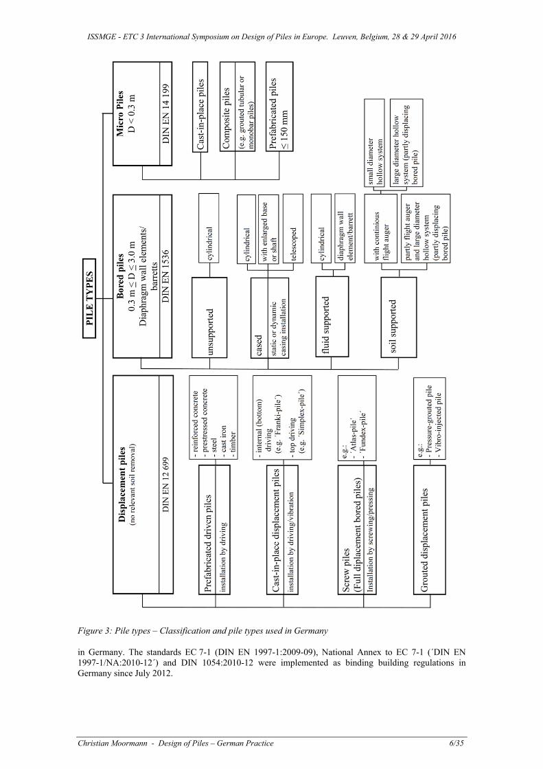
ISSMGE - ETC 3 International Symposium on Design of Piles in Europe Leuven Belgium 28 amp 29 April 2016
Christian Moormann - Design of Piles ndash German Practice 2135
54 SLS design
541 Axially loaded piles
If an appropriate examination reveals that the deformations of the pile foundation are relevant to the structure an analysis of the serviceability limit state (SLS) must be performed for the governing design situations Serviceability is demonstrated if the following condition is met
(SLS)R(SLS)RF(SLS)F kdkd (16)
Partial factors of = 10 are normally adopted for actions and resistances Analysis may also be performed using a value for the allowable settlements (acuteallow skacute) as provided by the structural designer assuming characteristic effects on the pile foundation in the serviceability limit state as follows
sk le allow sk (17)
Where pile systems only show minor settlements under service loads the serviceability limit state analysis can be covered in the analysis of the ultimate limit state according to the Note for clause 7641(2) of EC 7-1
According to acuteEA-Pfaumlhleacute (Section 641) it is assumed in a first step that single pile performance is prevalent for the pile foundation structure as a whole Regardless of this differential settlements sk between the piles of a piled foundation structure can occur even when single pile behaviour is anticipated Such effects can result eg of heterogeneous ground conditions andor influences from pile execution After Figure 9 differentiation is to be made between anticipated
minor differential settlements and substantial differential settlements within the pile group
If only minor differential settlements are anticipated between individual piles in a structure then the characteristic pile resistance shall be derived from an assessment of pile load test results or from a calculation with the empirical data of acuteEA-Pfaumlhleacute using a specified allowable characteristic settlement sk as shown in Figure 9 a) For the consideration of the ground-foundation-structure interaction spring constants may be adopted for the piles which are derived from the secant on the characteristic resistance-settlement or -heave curve or from empirical data
If substantial differential settlements are anticipated between the individual piles of a structure additionally possible upper skmax and lower bounds skmin of the settlements sk after Figure 9 b) shall be determined in the range of the resulting pile resistance R(SLS) adopting the following equation
Δsk = κ sk (18)
The factor depends on pile installation ground stratification and the locations of the piles within the foundation structure and should be specified in agreement with the geotechnical expert and recomendations by Kempfert 2009 It has to be checked whether as a result of these possible differential settlements between the piles or within a pile group for the characteristic pile resistance R(SLS) an ultimate limit state (ULS) or serviceability limit state (SLS) might result as a consequence of imposed effects in the pile head slab or the superstructure
a) b)
Figure 9 Possible method for derivation of characteristic resistances of isolated piles R(SLS) in the serviceability limit state from test data and data from resistance-settlement curves a) for anticipated minor differential settlements between isolated piles b) for anticipated substantial differential settlements between isolated piles
ISSMGE - ETC 3 International Symposium on Design of Piles in Europe Leuven Belgium 28 amp 29 April 2016
Christian Moormann - Design of Piles ndash German Practice 2235
For the evaluation of the settlments of axially loaded compression pile groups an approach that bases on nomogramms derived from numerical simulation of bored pile groups is provided by acuteEA-Pfaumlhleacute (section 82) which enables to calculate the settleemnt the average settlement of the pile group by
sG = sE Gs (19)
where sG mean settlement of a pile group sE settlement of a comparable single pile Gs settlement-related group factor for the mean settlement of a pile group
The settlement-related group factor Gs for determining the mean settlement of a pile group subject to a centrallyacting vertical action is given by
Gs = S1 S2 S3 (20)
where
S1 factor concerning the influence of the soil type and the group geometry (pile length L pile embedment depth in load-bearing ground d pile centre distances a
S2 group size influence factor S3 pile type influence factor
For the factors nomogrmms can be found in acuteEA-Pfaumlhleacute (section 82)
The obeservational method might be applied additionally to measure eg the settlement behaviour in the easiest case or even the pile loads distribution within a pile group or a piled raft in a more complex case In any case the observational method would be used in Germany to validate the analytical or numerical predicition but not for SLS design of axially loaded piles 542 Laterally loaded piles
For laterally loaded piles no specific rules or recommendation are provided by the German standards acuteEA-Pfaumlhleacute states that analytical approaches like using a lateral subgrade modulus p-y-curves might be not accurate enough to predict the lateral displacements reliably Therefore it is recommended that for more accurate analysis the modulus of subgrade reaction should be determined from horizontal pile load tests as a function of deflections and be adopted corresponding to the deflections resulting from the effects on the complete structure
55 Design based on load tests
The German acuteHandbook Eurocode 7 Part 1acute requests that generally the load-settlement behaviour of axially loaded piles respectively the lateral load-displacement behaviour of laterally loaded piles should be evaluated on the results of static pile load tests
For tension piles the execution of static axial pile load tests is considered to be mandatory whereas a calculation should be the exception
For micropiles under compression the execution of static pile load tests on at least 3 of all executed piles at the least at n = 2 piles is requested according to DIN EN 14199
In consequence the pile design based on load tests still plays an important role for pile design in Germany Beside static pile load test dynamic tests are executed quite frequently for onshore and offshore conditions Generally the reliability of dynamic load tests is considered to be lower than for static pile load tests and therefore higher correlation factors have to be applied for dynamic pile load tests Results of a round robin test on bored piles in sandy soil near Berlin (Baeszligler et al 2012 Herten et al 2013) also indicated that for cast-in-place bored and driven piles a quite large scattering of the analysis of the results of dynamic pile load tests may occur which makes dynamic pile load tests predominately applicable for prefabricated driven piles (made of concrete or steel) only
551 Static pile load tests
Recommendations for the planning and execution of static pile tests
The recommendation acuteEA-Pfaumlhleacute (Section 9) contains detailed recommendations on the planning and execution of static pile load tests covering all details like
Installation of test piles
ISSMGE - ETC 3 International Symposium on Design of Piles in Europe Leuven Belgium 28 amp 29 April 2016
Christian Moormann - Design of Piles ndash German Practice 2335
Test planning including number of piles test load instrumentation etc Loading system including reaction system hydraulic jacks etc Instrumentation and monitoring Testing procedure Evaluation of test data Documentation and reports
Such recommendations are provided by acuteEA-Pfaumlhleacute for static axial pile load tests for static lateral pile load tests for static pile load tests on micropiles (composite piles)
If the ultimate bearing resistance is not obvious from the form of the measured resistance-settlement curve for compression piles then
sg = sult = 010 Db (21)
can in approximation and for all pile systems be adopted for the limit settlement sg or sult where sult = settlement in the ultimate limit state and sg = limit settlement or failure settlement
Correlation factors from static pile tests
The characteristic pile resistances Rck (compression) and Rtk (tension) are determined from the data measured in static pile tests by dividing by the correlation factors i given in Handbook EC 7-1 Table A71 The German nationally determined parameters 1 and 2 are very close to the values proposed by EC 7-1 Table A9 but are not identical
For the ultimate compressive resistance the following equation must be fulfilled for structures incapable of redistributing loads from ldquoflexiblerdquo to ldquostiffrdquo compression piles
(22)
In the German approach the correlation factors 1 and 2 depend according to Table 11 (only) on the number of pile tests performed and are applied to the mean (Rcm)mean or the smallest value (Rcm)min of
cmR
If structures possess sufficient stiffness to redistribute loads from ldquoweakerrdquo to ldquostifferrdquo compression piles the numerical values of 1 and 2 may be divided by 11 assuming that 1 never becomes smaller than 10 There is no clear criterion for a ldquosufficient stiffrdquo structure There is the same approach but no such differentiation between piles of ldquoweakrdquo and ldquostiffrdquo structures for tension piles
Table 11 Correlation factors iξ for deriving characteristic pile resistances from static pile testing on
compression and tension piles
n 1 2 3 4 ge 5
1 135 125 115 105 100
2 135 115 100 100 100
n is the number of tested piles
552 Dynamic pile load tests
General comments on dynamic pile testing
In accordance with the Handbook EC 7-1 under certain circumstances the compressive pile resistances may also be derived from dynamic pile load tests Calibration against static pile tests is required to ensure that the damping factors for determining the dynamic component of the total resistance using direct methods are correctly selected Use of the extended method with complete modelling is considered to represent current best practice for determining pile resistances This method shall preferentially be adopted
If predominantly non-cohesive soils are prevalent in the load-bearing strata in which the piles are embedded and the testing institute can prove that extensive experience from dynamic pile tests is
ISSMGE - ETC 3 International Symposium on Design of Piles in Europe Leuven Belgium 28 amp 29 April 2016
Christian Moormann - Design of Piles ndash German Practice 2435
available for the region the characteristic pile resistances Rk may be derived even if no static pile load tests have been carried out on the site In this case Rk may be deducted from the tested or measured data from dynamic pile tests Rm with the correlation factors ξ56 and Δξ for the case calibration of dynamic pile load tests with static pile load tests carried out on similar construction projects The reason for this is the number of comparative dynamic and static pile load tests available for non-cohesive ground conditions in the whole of northern Germany and resultantly the availability of reliable calibrations and experience These provisions only apply to prefabricated driven piles
For dynamic load tests on piles in cohesive soils in accordance with the Handbook EC 7-1 acuteEA-Pfaumlhle`asks for the following procedure to be followed a) For piles in soils sensitive to creep and in unsaturated cohesive soils the results of dynamic pile load
tests shall always be calibrated against static pile load tests from the same site b) In saturated cohesive soils excessive porewater pressures can increase the capacities measured in
dynamic pile load tests Dynamic pile load tests may therefore not be adopted to determine the characteristic pile capacity if the pile base is situated in or the governing skin friction is mobilised in such soils
c) In deviation to the provisions in a) and b) dynamic pile load tests may be carried out in cohesive soils only if reliable regional empirical data are available and their applicability is expressly confirmed by a geotechnical expert for the respective case
When deriving characteristic pile resistances from dynamic pile load tests the following steps should normally be followed a) The testing institute employed for the dynamic pile load testing provides the test results in a test report
containing the test or measured data Rcmi = Rcstat differentiated into (Rcm)mean and (Rcm)min b) A plausibility check of the measured values is necessary in order to minimise uncertainties connected
with the dynamic load testing procedure To this end the geotechnical expert or geotechnical designer shall compare the mean dynamic pile load test values (Rcm)mean to the upper bounds of the calculated empirical data for the pile system or with local experience After carrying out the plausibility check the geotechnical expert or the geotechnical designer shall confirm or modify the mean value (Rcm)mean
c) The geotechnical expert or geotechnical designer then converts the test data or the modified values in accordance with a) and b) into characteristic pile resistances Rck on a project-specific basis for use in stability analyses In this process he shall take the stipulations in the Handbook EC 7-1 and Annex 42 into consideration
d) If the plausibility check after c) reveals significant differences and considerable assessment uncertainties it is recommended that the test data (raw data) be independently examined and evaluated again eg by means of a separate evaluation employing complete modelling The independent examination and evaluation is of particular importance for conditions falling into Geotechnical Category GC 3
The procedure for deriving characteristic pile resistances from dynamic pile load tests is in principle shown in Figure 10
Figure 10 Steps to determine characteristic pile resistances from measured or test data of dynamic pile load tests
ISSMGE - ETC 3 International Symposium on Design of Piles in Europe Leuven Belgium 28 amp 29 April 2016
Christian Moormann - Design of Piles ndash German Practice 2535
Table 12 Base values 0i with corresponding increase factors and model factors for correlation factors 5 and 6 used to derive characteristic values from impact or dynamic pile tests
0i for n = 2 5 10 15 ge 20
05 160 150 145 142 140
06 150 135 130 125 125
ndash n is the number of tested piles ndash Intermediate values of ξ05 and ξ06 for n = 2 to 20 may be linearly interpolated
a) To calculate the correlations factors ξi ∆ ∙ also see Figure 11
b) For the surcharge value Δξ
rarr Δξ = 0 for calibrating dynamic evaluation methods with static pile test results on the same site rarr Δξ = 010 for calibrating dynamic evaluation methods with static pile test results on a comparable construction project rarr Δξ = 040 for calibrating dynamic evaluation methods based on documented or common empirical data for pile resistances Adoption of a direct method such as the Case or TNO method is not permitted
c) The following apply to the model factor ηD for consideration of the evaluation method
rarr ηD = 100 for direct evaluation methods
rarr ηD = 085 For extended methods with complete modelling
d) If structures possess sufficient stiffness and strength to redistribute loads from ldquoweakerrdquo to ldquostifferrdquo piles the numerical values of ξ5 and ξ6 may be divided by 11
c) The following apply to the model factor ηD for consideration of pile driving formulae
rarr ηD = 105 if the wave equation method is adopted
rarr ηD = 110 if a pile driving formula with measurement of the quasi- elastic pile head movement under driving impact is adopted rarr ηD = 120 if a pile driving formula without measurement of the quasi- elastic pile head movement under driving impact is adopted
f) If different piles are used in the foundation groups of similar piles should be considered separately when selecting the number n of test piles This also applies to areas of similar ground conditions within the same site
Figure 11 Procedure for deriving the correlation factors ξ5 and ξ6 for dynamic pile load tests as a function of the calibration based on Table 12
ISSMGE - ETC 3 International Symposium on Design of Piles in Europe Leuven Belgium 28 amp 29 April 2016
Christian Moormann - Design of Piles ndash German Practice 2635
Recommendations for the planning and execution of dynamic pile tests
The recommendation acuteEA-Pfaumlhleacute (Section 10) contains detailed recommendations on the planning and execution of dynamic pile load tests covering all details like
Range of Application and General Conditions Theoretical Principles Description of Testing Methods Test Planning and Execution Evaluation and Interpretation of Dynamic Load Tests Calibrating Dynamic Pile Load Tests Qualifications of Testing Institutes and Personnel Documentations and Reporting Testing Driving Rig Suitability
Beside acuteconventionalacute dynamic tests also Rapid Load Tests are considered
Correlation factors from dynamic pile tests
The characteristic pile resistance Rck is determined from the data tested or measured in impact or dynamic pile tests by dividing by the I correlation factors The base values of the 0i correlation factors are used to calculate the i correlation factors together with the associated acutesurcharge factorsacute Δ and model factors ηD from Table 12 (Handbook EC 7-1 Table A72) and Figure 11 (Handbook EC 7-1 Figure A71)
For the ultimate compressive resistance the following equation must be fulfilled for structures incapable of redistributing loads from ldquoweakerrdquo to ldquostifferrdquo compression piles
(23)
5 and 6 are correlation factors which as for the static pile load tests depend (only) on the number of pile tests performed and are applied to the mean (Rcm)mean or the smallest value (Rcm)min of cmR
If structures possess sufficient stiffness to redistribute loads from ldquoweakerrdquo to ldquostifferrdquo compression piles the nume1rical values of 5 and 6 may be divided by 11
56 Design based on experience
There are no specific rules for ldquodesign based on experiencerdquo in Germany although the findings from pile foundations realized and tested under similar geotechnical and geometrical conditions is often considered as additional information for a current piling project
57 Structural safety
The structural design of piles is carried out according to the structural codes for concrete (EC 2) and steel (EC 3) and their national annexes
The German acuteRecommendations on Piling (EA-Pfaumlhle)acute provides additional recommendations on the structural design (section 59 acuteInternal pile Capacityacute) as well as on the execution of piles eg concerning the reinforcement and the required concrete cover for bored piles etc
Additionally the acuteEA-Pfaumlhleacute contain recommendations to evaluate the resistance of piles against buckling failure in soil strata with low lateral support providing a simplified approach for buckling analysis and to determine the characteristic resistance against pile buckling (Vogt amp Vogt 2013)
6 QUALITY CONTROL MONITORING AND TESTING PRACTICE
With regard to quality assurance during execution the requirements of the European execution standards issued for the individual pile types and the German prestandards (DIN SPEC) published to facilitate their use in Germany has to be considered in Germany Therefore it is common practice to document the piling execution with a record for each individual pile
acuteEA-Pfaumlhleacute (Section 11) provides additional recommendations for the quality assurance during pile execution especially for bored piles displacement piles and grouted micro piles and give hints for avoiding common mistakes
ISSMGE - ETC 3 International Symposium on Design of Piles in Europe Leuven Belgium 28 amp 29 April 2016
Christian Moormann - Design of Piles ndash German Practice 2735
As mentioned in sections 551 and 552 of this paper the recommendation acuteEA-Pfaumlhleacute contains also detailed information and recommendations for the planning and execution of both static and dynamic pile load tests
Section 12 of the acuteEA-Pfaumlhleacute provides an overview of pile integrity testing methods which serve to control pile quality and geometry after pile installation In this context
non-destructive ldquolow strainrdquo tests non-destructive ultrasonic method for testing the concrete in the pile shaft (ldquocross-holerdquo method
or ldquosingle holerdquo ultrasonic logging) and core drilling in the pile with core recovery and core testing andor video borehole surveys or
ldquosingle holerdquo tests
were discussed and recommendation for the execution of such tests are given
7 PARTICULAR NATIONAL EXPERIENCES AND DATABASES
The particular national experience with a wide spectrum of different pile types and with databases considering a huge number of results from static and dynamic axial pile load tests and their stochastic evaluation mentioned in section 532
8 DESIGN EXAMPLES
The most commonly used design methods for single standing axially loaded piles are illustrated in the following by three examples
Example 1 Determining the axial pile resistances from static pile load tests with ultimate and serviceability limit state analyses (section 81)
Example 2 Determining the characteristic axial pile resistances from empirical data for a bored pile (section 82)
Example 3 Determining the Characteristic Axial Pile Resistances from Empirical Data for a Prefabricated Driven Pile (section 83)
All three examples are taken from a collection of application and design examples which are added as an annex to the acuteRecommendations on Piling (EA-Pfaumlhle)acute
81 Example 1 Determining the axial pile resistances from static pile load tests with ultimate and serviceability limit state analyses
811 Objectives
Figure 12 shows a foundation situation with a pile of diameter D = 12 m and a permanent load FGk = 15 MN in addition to a variable load FQrepk = 10 MN Two static pile load tests were executed the results of which are included in Figure B11b and Table B11 as Rm1 and Rm2 The ultimate settlement is defined as sg = sult = 01 120 cm = 12 cm using Eq (8) As the static pile load tests were only executed up to a settlement s = 10 cm the ultimate settlement was extrapolated
a) b) Figure 12 a) System and effect b) Logged Rm values for both static pile load tests
Pile D = 120
ISSMGE - ETC 3 International Symposium on Design of Piles in Europe Leuven Belgium 28 amp 29 April 2016
Christian Moormann - Design of Piles ndash German Practice 2835
The analysis comprises the evaluation of the characteristic pile resistances in the ultimate limit state (ULS) and of the characteristic boundary lines in the serviceability limit state (SLS) as well as the external capacity and serviceability for the specified pile load The evaluation is done for both situations according to section 551 of this paper ie structures incapable to redistribute loads from acuteweakeracute to acutestifferacute piles als well as structure possesing sufficient stiffness to restribute loads from acuteweakeracute to acutestifferacute piles An allowable pile settlement allow sk = 20 cm is specified by the structural design for the serviceability limit state (SLS) The static pile load tests can be taken from Weiszlig amp Hanack (1983)
812 Deriving the characteristic pile resistances in the ultimate and serviceability limit states
The characteristic ultimate pile resistance Rck is given by the lesser of either the mean value (Rcm)mean or the minimum value (Rcm)min of the pile load test results using Equation (A41) as follows
The correlation factors 1 and 2 depend on the number of static pile load tests performed and are selected after section 55 The correlation factors given there apply to acuteless stiffacute structures (called ldquoflexiblerdquo) If ldquostiffrdquo structures are used the correlation factors may be divided by 11 assuming that 1 does not become smaller than 10
For the range of small pile settlements after section 541 Eq (17) characteristic boundary lines were derived for the serviceability limit state analysis using the values (based on Kempfert 2009) For the present case = 015 was adopted to relate to the average of the measured values a) b)
Figure 13 a) Characteristic pile resistances in the ultimate limit state (ULS) for piles of ldquoflexiblerdquo and ldquostiffrdquo structures derived from the Rmi values recorded in static pile load tests b) Section of the resistance-settlement curves in the serviceability limit state (SLS) and derivation of characteristic boundary curves
Note The method adopted here for the characteristic boundary lines in the service load range represents only one possible option Other reasoned procedures are also possible
Figure 13 and Table 13 show the results for the determination of Rck (SLS) and Rck = Rck (ULS)
ISSMGE - ETC 3 International Symposium on Design of Piles in Europe Leuven Belgium 28 amp 29 April 2016
Christian Moormann - Design of Piles ndash German Practice 2935
Table 13 Results of two static pile load tests and derivation of the characteristic resistance-settlement curves for piles of ldquoflexiblerdquo and ldquostiffrdquo structures
Settlement s
[cm]
Rm1
[MN]
Rm2
[MN]
(Rcm)mean
[MN]
(Rcm)min
[MN]
sk = middot sk
skmin [cm]
skmax [cm]
0 0 0 0 0 0 0
051 1483 1424 1454 1424 04 06
083 1891 1831 1861 1831 07 10
128 2458 2321 2390 2321 11 15
206 3015 2830 2922 2830 18 24
305 3427 3230 3329 3230 26 35
383 3750 3469 3610 3469
542 4301 3924 4112 3924
726 4803 4354 4579 4354 Flexible Stiff
971 5222 4881 5051 4881 1 2 1 2
120 5347 5060 5204 5060 125 115 114 105
Using the results from Table 13 the characteristic pile resistance Rck in the serviceability limit state (ULS) can be determined for piles of ldquoflexiblerdquo and ldquostiffrdquo structures in Table 14
Table 14 Deriving the characteristic pile resistance Rck in the ultimate limit state for piles of ldquoflexiblerdquo and ldquostiffrdquo structures
Piles of
[MN]
[MN] Rck [MN]
ldquoflexiblerdquo structures 4163 4400 4163
ldquostiffrdquo structures 4565 4819 4565
813 Bearing capacity analysis
The limit state condition (Section 51)
Fcd Rcd
must be adhered to for ultimate limit state (ULS) analysis a) For single piles acting independently (piles of a ldquoflexiblerdquo structure)
Fcd = FGk G + FQrepk Q = 1500 135 + 1000 150 = 3525 MN
Rcd = Rckt = 4163110 = 3785 MN
Fcd = 3525 MN lt Rcd = 3785 MN
b) For load distribution by means of a rigid capping slab (piles of a ldquostiffrdquo structure)
Fcd = 3525 MN
Rcd = Rckt = 4565110 = 4150 MN
Fcd = 3525 MN lt Rcd = 4150 MN
814 Serviceability analysis
When determining the pile resistances R(SLS) in the serviceability limit state differentiation after 54 is required whether minor or major (adopted here) differential pile settlements are to be expected To this end the characteristic boundary curves in the service load range were derived from the recorded pile load test data in Table 13 and Figure 13 b
ISSMGE - ETC 3 International Symposium on Design of Piles in Europe Leuven Belgium 28 amp 29 April 2016
Christian Moormann - Design of Piles ndash German Practice 3035
a) b)
Figure 14 a) Analysing serviceability via the characteristic pile forces b) Analysing serviceability via existing and allowable settlements
The specified allowable settlement (eg specified in the structural design) in the example is allow sk = 2 cm Using Figure 14 a serviceability is demonstrated via pile forces after 541 Eq (16) as
Fd (SLS) = Fk = 25 MN lt Rd (SLS) = Rk (SLS) = 27 MN
Analysis by comparing settlements in accordance with Figure 14 b after 63 Eq (17) results to
exist skmax = 18 cm lt allow sk = 20 cm
82 Example 2 Determining the characteristic axial pile resistances from empirical data for a bored pile
821 Objectives
Figure 15 (example taken from DIN 40141990-03) summarises the information on soil type ground strength and pile geometry necessary for the determination of the axial pile resistance Rck(s) based on empirical data
Figure 15 Ground profile penetration test diagram and dimensions for an example calculation of the resistance-settlement curve D = 09 m U = 283 m A = 064 m2
ISSMGE - ETC 3 International Symposium on Design of Piles in Europe Leuven Belgium 28 amp 29 April 2016
Christian Moormann - Design of Piles ndash German Practice 3135
The characteristic resistance-settlement curve shall be determined using the table data after 532 (Tables 9 to 10)
822 Analysis for lower and upper table values
Note Reference is made to the application principles and limitations in 543 in particular with regard to the upper table values In the example presented here both the lower and the upper table values are used as examples (not as a rule)
Determining the pile shaft resistance Rsk
The ultimate limit state skin friction values for the sand and the clay are given in Tables 8 and 10 in 532 By adopting the associated pile skin areas the ultimate limit state pile shaft resistances Rski are provided in Table 15 The settlement ssg in [cm] is calculated as follows adopting the ultimate limit state pile shaft resistance Rsk in [MN]
ssg = 050 Rsk + 050
Using the figures from the example the pile head settlement is
ssg = 050 1243 + 050 = 11 cm for the lower table values and
ssg = 050 1726 + 050 = 14 cm for the upper table values
Table 15 Ultimate pile shaft resistance for the lower and upper table values
Stratum i [m]
Asi [msup2]
cuki or qci [MNmsup2]
qski [MNmsup2]
Rski [MN]
220 to 520 848 010 0039 ndash 0051 0331 ndash 0432
520 to 770 707 700 0051 ndash 0075a) 0361 ndash 0530
770 to 1020 707 1100 0078 ndash 0108 0551 ndash 0764 a) Extrapolated data Rsk = 1243 ndash 1726 MN
Determining the pile base resistance Rbk
A mean soil strength is adopted in a region from 1 D (09 m) above and 3 D (3 D = 270 m) below the pile base to determine Rbk For this zone a mean cone resistance qcm = 175 MNmsup2 is shown in the penetration test diagram in Figure 15
The pile base capacity can be calculated by adopting the figures from Table 8 in 532 and taking the previously determined value of qcm into consideration Table 16 reproduces the calculated figures
Table 16 Pile base resistance for the lower and upper table values
Relative settlement sD
qbk [MNmsup2]
Rbk(s) [MN]
002
003
010
1225 ndash 1625
1575 ndash 2088
3250 ndash 4325
0784 ndash 1040
1008 ndash 1336
2080 ndash 2768
Characteristic resistance-settlement curve
The pile resistances calculated from the pile base and pile shaft resistances are listed in Tables 17 and 18 as a function of the pile head settlement and are given for the lower and upper values The settlement of the pile head for each value of the pile resistance Rck is given by the characteristic resistance-settlement curve in Figure 16
ISSMGE - ETC 3 International Symposium on Design of Piles in Europe Leuven Belgium 28 amp 29 April 2016
Christian Moormann - Design of Piles ndash German Practice 3235
Table 17 Pile resistance as a function of pile head settlement (lower values)
Relative settlement sD
Pile head settlement [cm]
Rsk(s) [MN]
Rbk(s) [MN]
Rck(s) [MN]
ssg 002 003 010
11 18 27 90
1243 1243 1243 1243
0479 0784 1008 2080
1722 2027 2251 3323
Table 18 Pile resistance as a function of pile head settlement (upper values)
Relative settlement sD
Pile head settlement [cm]
Rsk(s) [MN]
Rbk(s) [MN]
Rck(s) [MN]
ssg 002 003 010
14 18 27 90
1726 1726 1726 1726
0809 1040 1336 2768
2535 2766 3062 4494
Figure 16 Resistance-settlement curve a) Lower values b) Upper values
83 Example 3 Determining the characteristic axial pile resistances from empirical data for a prefabricated driven pile
831 Objective
Figure 17 summarises the information on soil type ground strength and pile geometry required to determine the axial pile resistance Rck(s) based on empirical data The characteristic resistance-settlement curve shall be determined using the table data after acuteEA-Pfaumlhleacute Section 532 (Tables 51 to 54)
832 Characteristic axial pile resistance from empirical data for lower and upper table values
Note Reference is made to the application principles and limitations in 532 in particular with regard to the upper table values In the example presented here both the lower and the upper table values are used as examples (not as a rule)
Determining the pile shaft resistance Rsk
The empirical skin friction values in the zones of the load-bearing non-cohesive soil and the weak cohesive soil are given by acuteEA-Pfaumlhleacute 52 and 54 in Section 544 Together with the corresponding pile skin areas taking the correlation factor for the skin area from acuteEA-Pfaumlhleacute Table 55 in Section 544 into consideration the pile shaft resistance upon mobilisation of the ultimate limit state state Rsk (ssg) is given in Table 19 and the pile shaft resistance Rsk (sg) at failure in Table 20
ISSMGE - ETC 3 International Symposium on Design of Piles in Europe Leuven Belgium 28 amp 29 April 2016
Christian Moormann - Design of Piles ndash German Practice 3335
Figure 17 Ground profile penetration test diagram and dimensions for an example calculation for the resistance-settlement curve
Table 19 Pile shaft resistance upon mobilisation of the ultimate limit state for the lower and upper table values
Stratum i [m]
Asi [msup2]
qci [MNmsup2]
qski (ssg) [MNmsup2]
s [ndash]
Rski (ssg) [MN]
10 to 203 1022 1750 0070 ndash 0098 10 0715 ndash 1002
Rsk (ssg) = 0715 ndash 1002 MN
Table 20 Shaft resistance at failure for the lower and upper table values
Stratum i [m]
Asi [msup2]
qci [MNmsup2]
qski (ssg) [MNmsup2]
s [ndash]
Rski (ssg) [MN]
130 to 203 1022 1750 0103 ndash 0134 10 1053 ndash 1370
Rsk (sg) = 1053 ndash 1370 MN
Upon mobilisation of the failure state the settlement in [cm] for the skin friction ssg adopting Rsk(ssg) in [MN] is determined using the following equation for the pile shaft resistance Rsk(ssg)
ssg = 050 Rsk(ssg)
Using the figures from the example the pile head settlement is
ssg = 050 0715 = 04 cm for the lower table values and
ssg = 050 1002 = 05 cm for the upper table values
Determining the pile base resistance Rbk
For determination of Rbk a mean soil strength is adopted from 4 Deq below to 1 Deq above the pile base The equivalent pile diameter of a square prefabricated driven pile is determined using
Deq = 113 middot as
Using the dimensions of the example the equivalent pile diameter is
Deq = 113 middot 035 = 040 m
The nominal value of the square pile base area in this case is
ISSMGE - ETC 3 International Symposium on Design of Piles in Europe Leuven Belgium 28 amp 29 April 2016
Christian Moormann - Design of Piles ndash German Practice 3435
Ab = as2 = 0352 = 0123 msup2
The penetration test diagram in Figure 17 displays a mean characteristic cone resistance along the respective length of
∙ ∙
155 sup2
Using the figures in acuteEA-Pfaumlhleacute Table 51 and referring to the previously determined value of qcm and the correlation factor for the pile base area in acuteEA-Pfaumlhleacute Table 55 (544) the pile base resistance can be calculated Table 21 contains the determined numerical values
Table 21 Pile base resistance for the lower and upper table values
Relative settlement sD
qbk [MNmsup2]
b [ndash]
Rbk(s) [MN]
0035
0100
4025 ndash 6550
7658 ndash 10265
10
10
0495 ndash 0806
0942 ndash 1263
Characteristic resistance-settlement curve
Tables 22 and 23 contain the pile resistances calculated for the lower and upper values from the pile base and shaft resistances as a function of the pile head settlement The settlement of the pile head for each value of the pile resistance Rck is given by the characteristic resistance-settlement curve in Figure 18
Table 22 Pile resistance as a function of pile head settlement (lower values)
Relative settlement sD
Pile head settlement [cm]
Rsk(s) [MN]
Rbk(s) [MN]
Rck(s) [MN]
ssg 0035 0100
04 14 40
0715 0809 1053
0141 0495 0942
0856 1304 1995
Table 23 Pile resistance as a function of pile head settlement (upper values)
Relative settlement sD
Pile head settlement [cm]
Rsk(s) [MN]
Rbk(s) [MN]
Rck(s) [MN]
ssg 0035 0100
05 14 40
1002 1097 1370
0288 0806 1263
1290 1903 2633
Figure 18 Resistance-settlement curve a) Lower values b) Upper values
ISSMGE - ETC 3 International Symposium on Design of Piles in Europe Leuven Belgium 28 amp 29 April 2016
Christian Moormann - Design of Piles ndash German Practice 3535
REFERENCES Baeszligler M Niederleithinger E Georgi S Herten M (2012) Evaluation of the dynamic load test on bored piles in sandy soil 9th Int Conf on testing and design methods for deep foundations - IS Kanazawa 2012 (Matsumoto ed) 2012 155-162
BGR Bundesanstalt fuumlr Geowissenschaften und Rohstoffe (2008) Geologische Karte der Bundesrepublik Deutschland 11000000 (GK 1000) Revised ed Hannover (online)
DGGT (2004) AK 21 Empfehlungen des Arbeitskreises bdquoPfaumlhleldquo EA-Pfaumlhle 1 Auflage Ernst amp Sohn Verlag Berlin 2004
DGGT (2012a) AK 21 Empfehlungen des Arbeitskreises bdquoPfaumlhleldquo EA-Pfaumlhle 2 Auflage Ernst amp Sohn Verlag Berlin 2012
DGGT (2012b) AK 21 Recommendation on Piling (EA-Pfaumlhle) 2 Auflage Ernst amp Sohn Verlag Berlin 2012
DIN (2011a) Handbuch EC 7-1 Handbuch Eurocode 7 ndash Geotechnische Bemessung Band 1 Allgemeine Regeln 1 Auflage Beuth Verlag Berlin 2011
DIN (2011b) Handbuch EC 7-2 Handbuch Eurocode 7 ndash Geotechnische Bemessung Band 2 Erkundung und Untersuchung 1 Auflage Beuth Verlag Berlin 2011
Elborg E-A (1993) Verbesserung der Vorhersagbarkeit des Last-Setzungsverhaltens von Bohrpfaumlhlen auf empirischer Grundlage Dissertation Technische Hochschule Darmstadt D 17 1993
Freudenberger W amp Schwerd K (eds 1996) Erlaumluterungen zur Geologischen Karte von Bayern 1500 000 Bayerisches Geologisches Landesamt Munich (online)
Katzenbach R Moormann Ch (1997) Design of axially loaded piles and pile groups in Germany Actual practice and recent research results Design of axially loaded piles European practice International Seminar ISSMFE ERTC3 Bruumlssel 17-18 April 1997 Balkema Rotterdam 177-201
Kempfert H-G Becker P (2007) Grundlagen und Ergebnisse der Ableitung von axialen Pfahlwiderstaumlnden aus Erfahrungswerten Bautechnik 84 2007 S441ndash449
Kempfert H-G (2009) 32 Pfahlgruumlndungen In Grundbautaschenbuch 7 Auflage Teil 3 Kapitel 32 Verlag Ernst amp Sohn 2009 S 73ndash277
Henningsen D amp Katzung G (2006) Einfuumlhrung in die Geologie Deutschlands 7th ed Spektrum Akademischer Verlag Munich ISBN 3-8274-1586-1
Herten M Baeszligler M Niederleithinter E Georgi S (2013) Bewertung dynamischer Pfahlprobe-belastungen an Bohrpfaumlhlen Pfahl-Symposium 2013 Mitteilungen des Instituts fuumlr Grundbau und Bodenmechanik Technische Universitaumlt Braunschweig Heft 96 2013 79ndash98
Luumlking J (2010) Tragverhalten von offenen Verdraumlngungspfaumlhlen unter Beruumlcksichtigung der Pfropfenbildung in nichtbindigen Boumlden Schriftenreihe Geotechnik Universitaumlt Kassel 2010 Heft 23
Moormann Ch (2015) Ansatz von Streuungsfaktoren bei statischen und dynamischen Pfahlprobe-belastungen Bautechnik Vol 92 Heft 4 2015 295-311
Moormann Ch amp Kempfert H-G (2015) Jahresbericht 2014 des Arbeitskreises bdquoPfaumlhle der Deutschen Gesellschaft fuumlr Geotechnik (DGGT) Bautechnik 91(12) 922-932
Moormann Ch (2015) Jahresbericht 2015 des Arbeitskreises bdquoPfaumlhleldquo der Deutschen Gesellschaft fuumlr Geotechnik (DGGT)Bautechnik Vol 92 Heft 12 2014 895-900
Pawlewicz MJ Steinshouer DW Gautier DL (2003) Map Showing Geology Oil and Gas Fields and Geologic Provinces of Europe including Turkey USGS Open File Report 97-470I US Department of the Interior US Geological Survey Denver CO (online)
Vogt N Vogt S (2013) Biegeknickwiderstand von Mikropfaumlhlen gemaumlszlig den Eurocodes Bautechnik 90(9) 550 ndash 558
Weiszlig K Hanack S Der Einfluss der Lagerungsdichte des Bodens und der Herstellung von Groszligbohrpfaumlhlen auf deren Tragfaumlhigkeit Mitteilung der Deutschen Gesellschaft fuumlr Bodenmechanik (DEGEBO) an der TU Berlin Heft 35 1983
Witzel M (2004) Zur Tragfaumlhigkeit und Gebrauchstauglichkeit von Verdraumlngungspfaumlhlen in bindigen und nichtbindigen Boumlden Schriftenreihe Geotechnik Universitaumlt Kassel Heft 15 2004
ISSMGE - ETC 3 International Symposium on Design of Piles in Europe Leuven Belgium 28 amp 29 April 2016
Christian Moormann - Design of Piles ndash German Practice 2235
For the evaluation of the settlments of axially loaded compression pile groups an approach that bases on nomogramms derived from numerical simulation of bored pile groups is provided by acuteEA-Pfaumlhleacute (section 82) which enables to calculate the settleemnt the average settlement of the pile group by
sG = sE Gs (19)
where sG mean settlement of a pile group sE settlement of a comparable single pile Gs settlement-related group factor for the mean settlement of a pile group
The settlement-related group factor Gs for determining the mean settlement of a pile group subject to a centrallyacting vertical action is given by
Gs = S1 S2 S3 (20)
where
S1 factor concerning the influence of the soil type and the group geometry (pile length L pile embedment depth in load-bearing ground d pile centre distances a
S2 group size influence factor S3 pile type influence factor
For the factors nomogrmms can be found in acuteEA-Pfaumlhleacute (section 82)
The obeservational method might be applied additionally to measure eg the settlement behaviour in the easiest case or even the pile loads distribution within a pile group or a piled raft in a more complex case In any case the observational method would be used in Germany to validate the analytical or numerical predicition but not for SLS design of axially loaded piles 542 Laterally loaded piles
For laterally loaded piles no specific rules or recommendation are provided by the German standards acuteEA-Pfaumlhleacute states that analytical approaches like using a lateral subgrade modulus p-y-curves might be not accurate enough to predict the lateral displacements reliably Therefore it is recommended that for more accurate analysis the modulus of subgrade reaction should be determined from horizontal pile load tests as a function of deflections and be adopted corresponding to the deflections resulting from the effects on the complete structure
55 Design based on load tests
The German acuteHandbook Eurocode 7 Part 1acute requests that generally the load-settlement behaviour of axially loaded piles respectively the lateral load-displacement behaviour of laterally loaded piles should be evaluated on the results of static pile load tests
For tension piles the execution of static axial pile load tests is considered to be mandatory whereas a calculation should be the exception
For micropiles under compression the execution of static pile load tests on at least 3 of all executed piles at the least at n = 2 piles is requested according to DIN EN 14199
In consequence the pile design based on load tests still plays an important role for pile design in Germany Beside static pile load test dynamic tests are executed quite frequently for onshore and offshore conditions Generally the reliability of dynamic load tests is considered to be lower than for static pile load tests and therefore higher correlation factors have to be applied for dynamic pile load tests Results of a round robin test on bored piles in sandy soil near Berlin (Baeszligler et al 2012 Herten et al 2013) also indicated that for cast-in-place bored and driven piles a quite large scattering of the analysis of the results of dynamic pile load tests may occur which makes dynamic pile load tests predominately applicable for prefabricated driven piles (made of concrete or steel) only
551 Static pile load tests
Recommendations for the planning and execution of static pile tests
The recommendation acuteEA-Pfaumlhleacute (Section 9) contains detailed recommendations on the planning and execution of static pile load tests covering all details like
Installation of test piles
ISSMGE - ETC 3 International Symposium on Design of Piles in Europe Leuven Belgium 28 amp 29 April 2016
Christian Moormann - Design of Piles ndash German Practice 2335
Test planning including number of piles test load instrumentation etc Loading system including reaction system hydraulic jacks etc Instrumentation and monitoring Testing procedure Evaluation of test data Documentation and reports
Such recommendations are provided by acuteEA-Pfaumlhleacute for static axial pile load tests for static lateral pile load tests for static pile load tests on micropiles (composite piles)
If the ultimate bearing resistance is not obvious from the form of the measured resistance-settlement curve for compression piles then
sg = sult = 010 Db (21)
can in approximation and for all pile systems be adopted for the limit settlement sg or sult where sult = settlement in the ultimate limit state and sg = limit settlement or failure settlement
Correlation factors from static pile tests
The characteristic pile resistances Rck (compression) and Rtk (tension) are determined from the data measured in static pile tests by dividing by the correlation factors i given in Handbook EC 7-1 Table A71 The German nationally determined parameters 1 and 2 are very close to the values proposed by EC 7-1 Table A9 but are not identical
For the ultimate compressive resistance the following equation must be fulfilled for structures incapable of redistributing loads from ldquoflexiblerdquo to ldquostiffrdquo compression piles
(22)
In the German approach the correlation factors 1 and 2 depend according to Table 11 (only) on the number of pile tests performed and are applied to the mean (Rcm)mean or the smallest value (Rcm)min of
cmR
If structures possess sufficient stiffness to redistribute loads from ldquoweakerrdquo to ldquostifferrdquo compression piles the numerical values of 1 and 2 may be divided by 11 assuming that 1 never becomes smaller than 10 There is no clear criterion for a ldquosufficient stiffrdquo structure There is the same approach but no such differentiation between piles of ldquoweakrdquo and ldquostiffrdquo structures for tension piles
Table 11 Correlation factors iξ for deriving characteristic pile resistances from static pile testing on
compression and tension piles
n 1 2 3 4 ge 5
1 135 125 115 105 100
2 135 115 100 100 100
n is the number of tested piles
552 Dynamic pile load tests
General comments on dynamic pile testing
In accordance with the Handbook EC 7-1 under certain circumstances the compressive pile resistances may also be derived from dynamic pile load tests Calibration against static pile tests is required to ensure that the damping factors for determining the dynamic component of the total resistance using direct methods are correctly selected Use of the extended method with complete modelling is considered to represent current best practice for determining pile resistances This method shall preferentially be adopted
If predominantly non-cohesive soils are prevalent in the load-bearing strata in which the piles are embedded and the testing institute can prove that extensive experience from dynamic pile tests is
ISSMGE - ETC 3 International Symposium on Design of Piles in Europe Leuven Belgium 28 amp 29 April 2016
Christian Moormann - Design of Piles ndash German Practice 2435
available for the region the characteristic pile resistances Rk may be derived even if no static pile load tests have been carried out on the site In this case Rk may be deducted from the tested or measured data from dynamic pile tests Rm with the correlation factors ξ56 and Δξ for the case calibration of dynamic pile load tests with static pile load tests carried out on similar construction projects The reason for this is the number of comparative dynamic and static pile load tests available for non-cohesive ground conditions in the whole of northern Germany and resultantly the availability of reliable calibrations and experience These provisions only apply to prefabricated driven piles
For dynamic load tests on piles in cohesive soils in accordance with the Handbook EC 7-1 acuteEA-Pfaumlhle`asks for the following procedure to be followed a) For piles in soils sensitive to creep and in unsaturated cohesive soils the results of dynamic pile load
tests shall always be calibrated against static pile load tests from the same site b) In saturated cohesive soils excessive porewater pressures can increase the capacities measured in
dynamic pile load tests Dynamic pile load tests may therefore not be adopted to determine the characteristic pile capacity if the pile base is situated in or the governing skin friction is mobilised in such soils
c) In deviation to the provisions in a) and b) dynamic pile load tests may be carried out in cohesive soils only if reliable regional empirical data are available and their applicability is expressly confirmed by a geotechnical expert for the respective case
When deriving characteristic pile resistances from dynamic pile load tests the following steps should normally be followed a) The testing institute employed for the dynamic pile load testing provides the test results in a test report
containing the test or measured data Rcmi = Rcstat differentiated into (Rcm)mean and (Rcm)min b) A plausibility check of the measured values is necessary in order to minimise uncertainties connected
with the dynamic load testing procedure To this end the geotechnical expert or geotechnical designer shall compare the mean dynamic pile load test values (Rcm)mean to the upper bounds of the calculated empirical data for the pile system or with local experience After carrying out the plausibility check the geotechnical expert or the geotechnical designer shall confirm or modify the mean value (Rcm)mean
c) The geotechnical expert or geotechnical designer then converts the test data or the modified values in accordance with a) and b) into characteristic pile resistances Rck on a project-specific basis for use in stability analyses In this process he shall take the stipulations in the Handbook EC 7-1 and Annex 42 into consideration
d) If the plausibility check after c) reveals significant differences and considerable assessment uncertainties it is recommended that the test data (raw data) be independently examined and evaluated again eg by means of a separate evaluation employing complete modelling The independent examination and evaluation is of particular importance for conditions falling into Geotechnical Category GC 3
The procedure for deriving characteristic pile resistances from dynamic pile load tests is in principle shown in Figure 10
Figure 10 Steps to determine characteristic pile resistances from measured or test data of dynamic pile load tests
ISSMGE - ETC 3 International Symposium on Design of Piles in Europe Leuven Belgium 28 amp 29 April 2016
Christian Moormann - Design of Piles ndash German Practice 2535
Table 12 Base values 0i with corresponding increase factors and model factors for correlation factors 5 and 6 used to derive characteristic values from impact or dynamic pile tests
0i for n = 2 5 10 15 ge 20
05 160 150 145 142 140
06 150 135 130 125 125
ndash n is the number of tested piles ndash Intermediate values of ξ05 and ξ06 for n = 2 to 20 may be linearly interpolated
a) To calculate the correlations factors ξi ∆ ∙ also see Figure 11
b) For the surcharge value Δξ
rarr Δξ = 0 for calibrating dynamic evaluation methods with static pile test results on the same site rarr Δξ = 010 for calibrating dynamic evaluation methods with static pile test results on a comparable construction project rarr Δξ = 040 for calibrating dynamic evaluation methods based on documented or common empirical data for pile resistances Adoption of a direct method such as the Case or TNO method is not permitted
c) The following apply to the model factor ηD for consideration of the evaluation method
rarr ηD = 100 for direct evaluation methods
rarr ηD = 085 For extended methods with complete modelling
d) If structures possess sufficient stiffness and strength to redistribute loads from ldquoweakerrdquo to ldquostifferrdquo piles the numerical values of ξ5 and ξ6 may be divided by 11
c) The following apply to the model factor ηD for consideration of pile driving formulae
rarr ηD = 105 if the wave equation method is adopted
rarr ηD = 110 if a pile driving formula with measurement of the quasi- elastic pile head movement under driving impact is adopted rarr ηD = 120 if a pile driving formula without measurement of the quasi- elastic pile head movement under driving impact is adopted
f) If different piles are used in the foundation groups of similar piles should be considered separately when selecting the number n of test piles This also applies to areas of similar ground conditions within the same site
Figure 11 Procedure for deriving the correlation factors ξ5 and ξ6 for dynamic pile load tests as a function of the calibration based on Table 12
ISSMGE - ETC 3 International Symposium on Design of Piles in Europe Leuven Belgium 28 amp 29 April 2016
Christian Moormann - Design of Piles ndash German Practice 2635
Recommendations for the planning and execution of dynamic pile tests
The recommendation acuteEA-Pfaumlhleacute (Section 10) contains detailed recommendations on the planning and execution of dynamic pile load tests covering all details like
Range of Application and General Conditions Theoretical Principles Description of Testing Methods Test Planning and Execution Evaluation and Interpretation of Dynamic Load Tests Calibrating Dynamic Pile Load Tests Qualifications of Testing Institutes and Personnel Documentations and Reporting Testing Driving Rig Suitability
Beside acuteconventionalacute dynamic tests also Rapid Load Tests are considered
Correlation factors from dynamic pile tests
The characteristic pile resistance Rck is determined from the data tested or measured in impact or dynamic pile tests by dividing by the I correlation factors The base values of the 0i correlation factors are used to calculate the i correlation factors together with the associated acutesurcharge factorsacute Δ and model factors ηD from Table 12 (Handbook EC 7-1 Table A72) and Figure 11 (Handbook EC 7-1 Figure A71)
For the ultimate compressive resistance the following equation must be fulfilled for structures incapable of redistributing loads from ldquoweakerrdquo to ldquostifferrdquo compression piles
(23)
5 and 6 are correlation factors which as for the static pile load tests depend (only) on the number of pile tests performed and are applied to the mean (Rcm)mean or the smallest value (Rcm)min of cmR
If structures possess sufficient stiffness to redistribute loads from ldquoweakerrdquo to ldquostifferrdquo compression piles the nume1rical values of 5 and 6 may be divided by 11
56 Design based on experience
There are no specific rules for ldquodesign based on experiencerdquo in Germany although the findings from pile foundations realized and tested under similar geotechnical and geometrical conditions is often considered as additional information for a current piling project
57 Structural safety
The structural design of piles is carried out according to the structural codes for concrete (EC 2) and steel (EC 3) and their national annexes
The German acuteRecommendations on Piling (EA-Pfaumlhle)acute provides additional recommendations on the structural design (section 59 acuteInternal pile Capacityacute) as well as on the execution of piles eg concerning the reinforcement and the required concrete cover for bored piles etc
Additionally the acuteEA-Pfaumlhleacute contain recommendations to evaluate the resistance of piles against buckling failure in soil strata with low lateral support providing a simplified approach for buckling analysis and to determine the characteristic resistance against pile buckling (Vogt amp Vogt 2013)
6 QUALITY CONTROL MONITORING AND TESTING PRACTICE
With regard to quality assurance during execution the requirements of the European execution standards issued for the individual pile types and the German prestandards (DIN SPEC) published to facilitate their use in Germany has to be considered in Germany Therefore it is common practice to document the piling execution with a record for each individual pile
acuteEA-Pfaumlhleacute (Section 11) provides additional recommendations for the quality assurance during pile execution especially for bored piles displacement piles and grouted micro piles and give hints for avoiding common mistakes
ISSMGE - ETC 3 International Symposium on Design of Piles in Europe Leuven Belgium 28 amp 29 April 2016
Christian Moormann - Design of Piles ndash German Practice 2735
As mentioned in sections 551 and 552 of this paper the recommendation acuteEA-Pfaumlhleacute contains also detailed information and recommendations for the planning and execution of both static and dynamic pile load tests
Section 12 of the acuteEA-Pfaumlhleacute provides an overview of pile integrity testing methods which serve to control pile quality and geometry after pile installation In this context
non-destructive ldquolow strainrdquo tests non-destructive ultrasonic method for testing the concrete in the pile shaft (ldquocross-holerdquo method
or ldquosingle holerdquo ultrasonic logging) and core drilling in the pile with core recovery and core testing andor video borehole surveys or
ldquosingle holerdquo tests
were discussed and recommendation for the execution of such tests are given
7 PARTICULAR NATIONAL EXPERIENCES AND DATABASES
The particular national experience with a wide spectrum of different pile types and with databases considering a huge number of results from static and dynamic axial pile load tests and their stochastic evaluation mentioned in section 532
8 DESIGN EXAMPLES
The most commonly used design methods for single standing axially loaded piles are illustrated in the following by three examples
Example 1 Determining the axial pile resistances from static pile load tests with ultimate and serviceability limit state analyses (section 81)
Example 2 Determining the characteristic axial pile resistances from empirical data for a bored pile (section 82)
Example 3 Determining the Characteristic Axial Pile Resistances from Empirical Data for a Prefabricated Driven Pile (section 83)
All three examples are taken from a collection of application and design examples which are added as an annex to the acuteRecommendations on Piling (EA-Pfaumlhle)acute
81 Example 1 Determining the axial pile resistances from static pile load tests with ultimate and serviceability limit state analyses
811 Objectives
Figure 12 shows a foundation situation with a pile of diameter D = 12 m and a permanent load FGk = 15 MN in addition to a variable load FQrepk = 10 MN Two static pile load tests were executed the results of which are included in Figure B11b and Table B11 as Rm1 and Rm2 The ultimate settlement is defined as sg = sult = 01 120 cm = 12 cm using Eq (8) As the static pile load tests were only executed up to a settlement s = 10 cm the ultimate settlement was extrapolated
a) b) Figure 12 a) System and effect b) Logged Rm values for both static pile load tests
Pile D = 120
ISSMGE - ETC 3 International Symposium on Design of Piles in Europe Leuven Belgium 28 amp 29 April 2016
Christian Moormann - Design of Piles ndash German Practice 2835
The analysis comprises the evaluation of the characteristic pile resistances in the ultimate limit state (ULS) and of the characteristic boundary lines in the serviceability limit state (SLS) as well as the external capacity and serviceability for the specified pile load The evaluation is done for both situations according to section 551 of this paper ie structures incapable to redistribute loads from acuteweakeracute to acutestifferacute piles als well as structure possesing sufficient stiffness to restribute loads from acuteweakeracute to acutestifferacute piles An allowable pile settlement allow sk = 20 cm is specified by the structural design for the serviceability limit state (SLS) The static pile load tests can be taken from Weiszlig amp Hanack (1983)
812 Deriving the characteristic pile resistances in the ultimate and serviceability limit states
The characteristic ultimate pile resistance Rck is given by the lesser of either the mean value (Rcm)mean or the minimum value (Rcm)min of the pile load test results using Equation (A41) as follows
The correlation factors 1 and 2 depend on the number of static pile load tests performed and are selected after section 55 The correlation factors given there apply to acuteless stiffacute structures (called ldquoflexiblerdquo) If ldquostiffrdquo structures are used the correlation factors may be divided by 11 assuming that 1 does not become smaller than 10
For the range of small pile settlements after section 541 Eq (17) characteristic boundary lines were derived for the serviceability limit state analysis using the values (based on Kempfert 2009) For the present case = 015 was adopted to relate to the average of the measured values a) b)
Figure 13 a) Characteristic pile resistances in the ultimate limit state (ULS) for piles of ldquoflexiblerdquo and ldquostiffrdquo structures derived from the Rmi values recorded in static pile load tests b) Section of the resistance-settlement curves in the serviceability limit state (SLS) and derivation of characteristic boundary curves
Note The method adopted here for the characteristic boundary lines in the service load range represents only one possible option Other reasoned procedures are also possible
Figure 13 and Table 13 show the results for the determination of Rck (SLS) and Rck = Rck (ULS)
ISSMGE - ETC 3 International Symposium on Design of Piles in Europe Leuven Belgium 28 amp 29 April 2016
Christian Moormann - Design of Piles ndash German Practice 2935
Table 13 Results of two static pile load tests and derivation of the characteristic resistance-settlement curves for piles of ldquoflexiblerdquo and ldquostiffrdquo structures
Settlement s
[cm]
Rm1
[MN]
Rm2
[MN]
(Rcm)mean
[MN]
(Rcm)min
[MN]
sk = middot sk
skmin [cm]
skmax [cm]
0 0 0 0 0 0 0
051 1483 1424 1454 1424 04 06
083 1891 1831 1861 1831 07 10
128 2458 2321 2390 2321 11 15
206 3015 2830 2922 2830 18 24
305 3427 3230 3329 3230 26 35
383 3750 3469 3610 3469
542 4301 3924 4112 3924
726 4803 4354 4579 4354 Flexible Stiff
971 5222 4881 5051 4881 1 2 1 2
120 5347 5060 5204 5060 125 115 114 105
Using the results from Table 13 the characteristic pile resistance Rck in the serviceability limit state (ULS) can be determined for piles of ldquoflexiblerdquo and ldquostiffrdquo structures in Table 14
Table 14 Deriving the characteristic pile resistance Rck in the ultimate limit state for piles of ldquoflexiblerdquo and ldquostiffrdquo structures
Piles of
[MN]
[MN] Rck [MN]
ldquoflexiblerdquo structures 4163 4400 4163
ldquostiffrdquo structures 4565 4819 4565
813 Bearing capacity analysis
The limit state condition (Section 51)
Fcd Rcd
must be adhered to for ultimate limit state (ULS) analysis a) For single piles acting independently (piles of a ldquoflexiblerdquo structure)
Fcd = FGk G + FQrepk Q = 1500 135 + 1000 150 = 3525 MN
Rcd = Rckt = 4163110 = 3785 MN
Fcd = 3525 MN lt Rcd = 3785 MN
b) For load distribution by means of a rigid capping slab (piles of a ldquostiffrdquo structure)
Fcd = 3525 MN
Rcd = Rckt = 4565110 = 4150 MN
Fcd = 3525 MN lt Rcd = 4150 MN
814 Serviceability analysis
When determining the pile resistances R(SLS) in the serviceability limit state differentiation after 54 is required whether minor or major (adopted here) differential pile settlements are to be expected To this end the characteristic boundary curves in the service load range were derived from the recorded pile load test data in Table 13 and Figure 13 b
ISSMGE - ETC 3 International Symposium on Design of Piles in Europe Leuven Belgium 28 amp 29 April 2016
Christian Moormann - Design of Piles ndash German Practice 3035
a) b)
Figure 14 a) Analysing serviceability via the characteristic pile forces b) Analysing serviceability via existing and allowable settlements
The specified allowable settlement (eg specified in the structural design) in the example is allow sk = 2 cm Using Figure 14 a serviceability is demonstrated via pile forces after 541 Eq (16) as
Fd (SLS) = Fk = 25 MN lt Rd (SLS) = Rk (SLS) = 27 MN
Analysis by comparing settlements in accordance with Figure 14 b after 63 Eq (17) results to
exist skmax = 18 cm lt allow sk = 20 cm
82 Example 2 Determining the characteristic axial pile resistances from empirical data for a bored pile
821 Objectives
Figure 15 (example taken from DIN 40141990-03) summarises the information on soil type ground strength and pile geometry necessary for the determination of the axial pile resistance Rck(s) based on empirical data
Figure 15 Ground profile penetration test diagram and dimensions for an example calculation of the resistance-settlement curve D = 09 m U = 283 m A = 064 m2
ISSMGE - ETC 3 International Symposium on Design of Piles in Europe Leuven Belgium 28 amp 29 April 2016
Christian Moormann - Design of Piles ndash German Practice 3135
The characteristic resistance-settlement curve shall be determined using the table data after 532 (Tables 9 to 10)
822 Analysis for lower and upper table values
Note Reference is made to the application principles and limitations in 543 in particular with regard to the upper table values In the example presented here both the lower and the upper table values are used as examples (not as a rule)
Determining the pile shaft resistance Rsk
The ultimate limit state skin friction values for the sand and the clay are given in Tables 8 and 10 in 532 By adopting the associated pile skin areas the ultimate limit state pile shaft resistances Rski are provided in Table 15 The settlement ssg in [cm] is calculated as follows adopting the ultimate limit state pile shaft resistance Rsk in [MN]
ssg = 050 Rsk + 050
Using the figures from the example the pile head settlement is
ssg = 050 1243 + 050 = 11 cm for the lower table values and
ssg = 050 1726 + 050 = 14 cm for the upper table values
Table 15 Ultimate pile shaft resistance for the lower and upper table values
Stratum i [m]
Asi [msup2]
cuki or qci [MNmsup2]
qski [MNmsup2]
Rski [MN]
220 to 520 848 010 0039 ndash 0051 0331 ndash 0432
520 to 770 707 700 0051 ndash 0075a) 0361 ndash 0530
770 to 1020 707 1100 0078 ndash 0108 0551 ndash 0764 a) Extrapolated data Rsk = 1243 ndash 1726 MN
Determining the pile base resistance Rbk
A mean soil strength is adopted in a region from 1 D (09 m) above and 3 D (3 D = 270 m) below the pile base to determine Rbk For this zone a mean cone resistance qcm = 175 MNmsup2 is shown in the penetration test diagram in Figure 15
The pile base capacity can be calculated by adopting the figures from Table 8 in 532 and taking the previously determined value of qcm into consideration Table 16 reproduces the calculated figures
Table 16 Pile base resistance for the lower and upper table values
Relative settlement sD
qbk [MNmsup2]
Rbk(s) [MN]
002
003
010
1225 ndash 1625
1575 ndash 2088
3250 ndash 4325
0784 ndash 1040
1008 ndash 1336
2080 ndash 2768
Characteristic resistance-settlement curve
The pile resistances calculated from the pile base and pile shaft resistances are listed in Tables 17 and 18 as a function of the pile head settlement and are given for the lower and upper values The settlement of the pile head for each value of the pile resistance Rck is given by the characteristic resistance-settlement curve in Figure 16
ISSMGE - ETC 3 International Symposium on Design of Piles in Europe Leuven Belgium 28 amp 29 April 2016
Christian Moormann - Design of Piles ndash German Practice 3235
Table 17 Pile resistance as a function of pile head settlement (lower values)
Relative settlement sD
Pile head settlement [cm]
Rsk(s) [MN]
Rbk(s) [MN]
Rck(s) [MN]
ssg 002 003 010
11 18 27 90
1243 1243 1243 1243
0479 0784 1008 2080
1722 2027 2251 3323
Table 18 Pile resistance as a function of pile head settlement (upper values)
Relative settlement sD
Pile head settlement [cm]
Rsk(s) [MN]
Rbk(s) [MN]
Rck(s) [MN]
ssg 002 003 010
14 18 27 90
1726 1726 1726 1726
0809 1040 1336 2768
2535 2766 3062 4494
Figure 16 Resistance-settlement curve a) Lower values b) Upper values
83 Example 3 Determining the characteristic axial pile resistances from empirical data for a prefabricated driven pile
831 Objective
Figure 17 summarises the information on soil type ground strength and pile geometry required to determine the axial pile resistance Rck(s) based on empirical data The characteristic resistance-settlement curve shall be determined using the table data after acuteEA-Pfaumlhleacute Section 532 (Tables 51 to 54)
832 Characteristic axial pile resistance from empirical data for lower and upper table values
Note Reference is made to the application principles and limitations in 532 in particular with regard to the upper table values In the example presented here both the lower and the upper table values are used as examples (not as a rule)
Determining the pile shaft resistance Rsk
The empirical skin friction values in the zones of the load-bearing non-cohesive soil and the weak cohesive soil are given by acuteEA-Pfaumlhleacute 52 and 54 in Section 544 Together with the corresponding pile skin areas taking the correlation factor for the skin area from acuteEA-Pfaumlhleacute Table 55 in Section 544 into consideration the pile shaft resistance upon mobilisation of the ultimate limit state state Rsk (ssg) is given in Table 19 and the pile shaft resistance Rsk (sg) at failure in Table 20
ISSMGE - ETC 3 International Symposium on Design of Piles in Europe Leuven Belgium 28 amp 29 April 2016
Christian Moormann - Design of Piles ndash German Practice 3335
Figure 17 Ground profile penetration test diagram and dimensions for an example calculation for the resistance-settlement curve
Table 19 Pile shaft resistance upon mobilisation of the ultimate limit state for the lower and upper table values
Stratum i [m]
Asi [msup2]
qci [MNmsup2]
qski (ssg) [MNmsup2]
s [ndash]
Rski (ssg) [MN]
10 to 203 1022 1750 0070 ndash 0098 10 0715 ndash 1002
Rsk (ssg) = 0715 ndash 1002 MN
Table 20 Shaft resistance at failure for the lower and upper table values
Stratum i [m]
Asi [msup2]
qci [MNmsup2]
qski (ssg) [MNmsup2]
s [ndash]
Rski (ssg) [MN]
130 to 203 1022 1750 0103 ndash 0134 10 1053 ndash 1370
Rsk (sg) = 1053 ndash 1370 MN
Upon mobilisation of the failure state the settlement in [cm] for the skin friction ssg adopting Rsk(ssg) in [MN] is determined using the following equation for the pile shaft resistance Rsk(ssg)
ssg = 050 Rsk(ssg)
Using the figures from the example the pile head settlement is
ssg = 050 0715 = 04 cm for the lower table values and
ssg = 050 1002 = 05 cm for the upper table values
Determining the pile base resistance Rbk
For determination of Rbk a mean soil strength is adopted from 4 Deq below to 1 Deq above the pile base The equivalent pile diameter of a square prefabricated driven pile is determined using
Deq = 113 middot as
Using the dimensions of the example the equivalent pile diameter is
Deq = 113 middot 035 = 040 m
The nominal value of the square pile base area in this case is
ISSMGE - ETC 3 International Symposium on Design of Piles in Europe Leuven Belgium 28 amp 29 April 2016
Christian Moormann - Design of Piles ndash German Practice 3435
Ab = as2 = 0352 = 0123 msup2
The penetration test diagram in Figure 17 displays a mean characteristic cone resistance along the respective length of
∙ ∙
155 sup2
Using the figures in acuteEA-Pfaumlhleacute Table 51 and referring to the previously determined value of qcm and the correlation factor for the pile base area in acuteEA-Pfaumlhleacute Table 55 (544) the pile base resistance can be calculated Table 21 contains the determined numerical values
Table 21 Pile base resistance for the lower and upper table values
Relative settlement sD
qbk [MNmsup2]
b [ndash]
Rbk(s) [MN]
0035
0100
4025 ndash 6550
7658 ndash 10265
10
10
0495 ndash 0806
0942 ndash 1263
Characteristic resistance-settlement curve
Tables 22 and 23 contain the pile resistances calculated for the lower and upper values from the pile base and shaft resistances as a function of the pile head settlement The settlement of the pile head for each value of the pile resistance Rck is given by the characteristic resistance-settlement curve in Figure 18
Table 22 Pile resistance as a function of pile head settlement (lower values)
Relative settlement sD
Pile head settlement [cm]
Rsk(s) [MN]
Rbk(s) [MN]
Rck(s) [MN]
ssg 0035 0100
04 14 40
0715 0809 1053
0141 0495 0942
0856 1304 1995
Table 23 Pile resistance as a function of pile head settlement (upper values)
Relative settlement sD
Pile head settlement [cm]
Rsk(s) [MN]
Rbk(s) [MN]
Rck(s) [MN]
ssg 0035 0100
05 14 40
1002 1097 1370
0288 0806 1263
1290 1903 2633
Figure 18 Resistance-settlement curve a) Lower values b) Upper values
ISSMGE - ETC 3 International Symposium on Design of Piles in Europe Leuven Belgium 28 amp 29 April 2016
Christian Moormann - Design of Piles ndash German Practice 3535
REFERENCES Baeszligler M Niederleithinger E Georgi S Herten M (2012) Evaluation of the dynamic load test on bored piles in sandy soil 9th Int Conf on testing and design methods for deep foundations - IS Kanazawa 2012 (Matsumoto ed) 2012 155-162
BGR Bundesanstalt fuumlr Geowissenschaften und Rohstoffe (2008) Geologische Karte der Bundesrepublik Deutschland 11000000 (GK 1000) Revised ed Hannover (online)
DGGT (2004) AK 21 Empfehlungen des Arbeitskreises bdquoPfaumlhleldquo EA-Pfaumlhle 1 Auflage Ernst amp Sohn Verlag Berlin 2004
DGGT (2012a) AK 21 Empfehlungen des Arbeitskreises bdquoPfaumlhleldquo EA-Pfaumlhle 2 Auflage Ernst amp Sohn Verlag Berlin 2012
DGGT (2012b) AK 21 Recommendation on Piling (EA-Pfaumlhle) 2 Auflage Ernst amp Sohn Verlag Berlin 2012
DIN (2011a) Handbuch EC 7-1 Handbuch Eurocode 7 ndash Geotechnische Bemessung Band 1 Allgemeine Regeln 1 Auflage Beuth Verlag Berlin 2011
DIN (2011b) Handbuch EC 7-2 Handbuch Eurocode 7 ndash Geotechnische Bemessung Band 2 Erkundung und Untersuchung 1 Auflage Beuth Verlag Berlin 2011
Elborg E-A (1993) Verbesserung der Vorhersagbarkeit des Last-Setzungsverhaltens von Bohrpfaumlhlen auf empirischer Grundlage Dissertation Technische Hochschule Darmstadt D 17 1993
Freudenberger W amp Schwerd K (eds 1996) Erlaumluterungen zur Geologischen Karte von Bayern 1500 000 Bayerisches Geologisches Landesamt Munich (online)
Katzenbach R Moormann Ch (1997) Design of axially loaded piles and pile groups in Germany Actual practice and recent research results Design of axially loaded piles European practice International Seminar ISSMFE ERTC3 Bruumlssel 17-18 April 1997 Balkema Rotterdam 177-201
Kempfert H-G Becker P (2007) Grundlagen und Ergebnisse der Ableitung von axialen Pfahlwiderstaumlnden aus Erfahrungswerten Bautechnik 84 2007 S441ndash449
Kempfert H-G (2009) 32 Pfahlgruumlndungen In Grundbautaschenbuch 7 Auflage Teil 3 Kapitel 32 Verlag Ernst amp Sohn 2009 S 73ndash277
Henningsen D amp Katzung G (2006) Einfuumlhrung in die Geologie Deutschlands 7th ed Spektrum Akademischer Verlag Munich ISBN 3-8274-1586-1
Herten M Baeszligler M Niederleithinter E Georgi S (2013) Bewertung dynamischer Pfahlprobe-belastungen an Bohrpfaumlhlen Pfahl-Symposium 2013 Mitteilungen des Instituts fuumlr Grundbau und Bodenmechanik Technische Universitaumlt Braunschweig Heft 96 2013 79ndash98
Luumlking J (2010) Tragverhalten von offenen Verdraumlngungspfaumlhlen unter Beruumlcksichtigung der Pfropfenbildung in nichtbindigen Boumlden Schriftenreihe Geotechnik Universitaumlt Kassel 2010 Heft 23
Moormann Ch (2015) Ansatz von Streuungsfaktoren bei statischen und dynamischen Pfahlprobe-belastungen Bautechnik Vol 92 Heft 4 2015 295-311
Moormann Ch amp Kempfert H-G (2015) Jahresbericht 2014 des Arbeitskreises bdquoPfaumlhle der Deutschen Gesellschaft fuumlr Geotechnik (DGGT) Bautechnik 91(12) 922-932
Moormann Ch (2015) Jahresbericht 2015 des Arbeitskreises bdquoPfaumlhleldquo der Deutschen Gesellschaft fuumlr Geotechnik (DGGT)Bautechnik Vol 92 Heft 12 2014 895-900
Pawlewicz MJ Steinshouer DW Gautier DL (2003) Map Showing Geology Oil and Gas Fields and Geologic Provinces of Europe including Turkey USGS Open File Report 97-470I US Department of the Interior US Geological Survey Denver CO (online)
Vogt N Vogt S (2013) Biegeknickwiderstand von Mikropfaumlhlen gemaumlszlig den Eurocodes Bautechnik 90(9) 550 ndash 558
Weiszlig K Hanack S Der Einfluss der Lagerungsdichte des Bodens und der Herstellung von Groszligbohrpfaumlhlen auf deren Tragfaumlhigkeit Mitteilung der Deutschen Gesellschaft fuumlr Bodenmechanik (DEGEBO) an der TU Berlin Heft 35 1983
Witzel M (2004) Zur Tragfaumlhigkeit und Gebrauchstauglichkeit von Verdraumlngungspfaumlhlen in bindigen und nichtbindigen Boumlden Schriftenreihe Geotechnik Universitaumlt Kassel Heft 15 2004

ISSMGE - ETC 3 International Symposium on Design of Piles in Europe Leuven Belgium 28 amp 29 April 2016
Christian Moormann - Design of Piles ndash German Practice 3535
REFERENCES Baeszligler M Niederleithinger E Georgi S Herten M (2012) Evaluation of the dynamic load test on bored piles in sandy soil 9th Int Conf on testing and design methods for deep foundations - IS Kanazawa 2012 (Matsumoto ed) 2012 155-162
BGR Bundesanstalt fuumlr Geowissenschaften und Rohstoffe (2008) Geologische Karte der Bundesrepublik Deutschland 11000000 (GK 1000) Revised ed Hannover (online)
DGGT (2004) AK 21 Empfehlungen des Arbeitskreises bdquoPfaumlhleldquo EA-Pfaumlhle 1 Auflage Ernst amp Sohn Verlag Berlin 2004
DGGT (2012a) AK 21 Empfehlungen des Arbeitskreises bdquoPfaumlhleldquo EA-Pfaumlhle 2 Auflage Ernst amp Sohn Verlag Berlin 2012
DGGT (2012b) AK 21 Recommendation on Piling (EA-Pfaumlhle) 2 Auflage Ernst amp Sohn Verlag Berlin 2012
DIN (2011a) Handbuch EC 7-1 Handbuch Eurocode 7 ndash Geotechnische Bemessung Band 1 Allgemeine Regeln 1 Auflage Beuth Verlag Berlin 2011
DIN (2011b) Handbuch EC 7-2 Handbuch Eurocode 7 ndash Geotechnische Bemessung Band 2 Erkundung und Untersuchung 1 Auflage Beuth Verlag Berlin 2011
Elborg E-A (1993) Verbesserung der Vorhersagbarkeit des Last-Setzungsverhaltens von Bohrpfaumlhlen auf empirischer Grundlage Dissertation Technische Hochschule Darmstadt D 17 1993
Freudenberger W amp Schwerd K (eds 1996) Erlaumluterungen zur Geologischen Karte von Bayern 1500 000 Bayerisches Geologisches Landesamt Munich (online)
Katzenbach R Moormann Ch (1997) Design of axially loaded piles and pile groups in Germany Actual practice and recent research results Design of axially loaded piles European practice International Seminar ISSMFE ERTC3 Bruumlssel 17-18 April 1997 Balkema Rotterdam 177-201
Kempfert H-G Becker P (2007) Grundlagen und Ergebnisse der Ableitung von axialen Pfahlwiderstaumlnden aus Erfahrungswerten Bautechnik 84 2007 S441ndash449
Kempfert H-G (2009) 32 Pfahlgruumlndungen In Grundbautaschenbuch 7 Auflage Teil 3 Kapitel 32 Verlag Ernst amp Sohn 2009 S 73ndash277
Henningsen D amp Katzung G (2006) Einfuumlhrung in die Geologie Deutschlands 7th ed Spektrum Akademischer Verlag Munich ISBN 3-8274-1586-1
Herten M Baeszligler M Niederleithinter E Georgi S (2013) Bewertung dynamischer Pfahlprobe-belastungen an Bohrpfaumlhlen Pfahl-Symposium 2013 Mitteilungen des Instituts fuumlr Grundbau und Bodenmechanik Technische Universitaumlt Braunschweig Heft 96 2013 79ndash98
Luumlking J (2010) Tragverhalten von offenen Verdraumlngungspfaumlhlen unter Beruumlcksichtigung der Pfropfenbildung in nichtbindigen Boumlden Schriftenreihe Geotechnik Universitaumlt Kassel 2010 Heft 23
Moormann Ch (2015) Ansatz von Streuungsfaktoren bei statischen und dynamischen Pfahlprobe-belastungen Bautechnik Vol 92 Heft 4 2015 295-311
Moormann Ch amp Kempfert H-G (2015) Jahresbericht 2014 des Arbeitskreises bdquoPfaumlhle der Deutschen Gesellschaft fuumlr Geotechnik (DGGT) Bautechnik 91(12) 922-932
Moormann Ch (2015) Jahresbericht 2015 des Arbeitskreises bdquoPfaumlhleldquo der Deutschen Gesellschaft fuumlr Geotechnik (DGGT)Bautechnik Vol 92 Heft 12 2014 895-900
Pawlewicz MJ Steinshouer DW Gautier DL (2003) Map Showing Geology Oil and Gas Fields and Geologic Provinces of Europe including Turkey USGS Open File Report 97-470I US Department of the Interior US Geological Survey Denver CO (online)
Vogt N Vogt S (2013) Biegeknickwiderstand von Mikropfaumlhlen gemaumlszlig den Eurocodes Bautechnik 90(9) 550 ndash 558
Weiszlig K Hanack S Der Einfluss der Lagerungsdichte des Bodens und der Herstellung von Groszligbohrpfaumlhlen auf deren Tragfaumlhigkeit Mitteilung der Deutschen Gesellschaft fuumlr Bodenmechanik (DEGEBO) an der TU Berlin Heft 35 1983
Witzel M (2004) Zur Tragfaumlhigkeit und Gebrauchstauglichkeit von Verdraumlngungspfaumlhlen in bindigen und nichtbindigen Boumlden Schriftenreihe Geotechnik Universitaumlt Kassel Heft 15 2004