design process error-proofing: benchmarking the...
TRANSCRIPT

1
Design Process Error-Proofing: Benchmarking the NASA Development Life-Cycle
Lawrence P. Chao*, Irem Tumer†, and Kosuke Ishii*
*Department of Mechanical Engineering, Design Division, Stanford University, Stanford, CA 94305-4022 †NASA Ames Research Center, Moffett Field, CA, 94035-1000
Abstract— This report describes the practices of the development life-cycle observed at NASA. Through a number of interviews and surveys of the NASA experience, including current projects such as Aura, CALIPSO, Kepler, SAGE and SOFIA, this research attempts to capture the design methods and culture present. The NASA development methods are shared and compared with industry practices, including gated realization processes, portfolio management, and platform design. The goal of this work is to identify best practices and lessons learned from NASA’s design and review experience, benchmark against industry techniques, and develop strategies to improve the process. With better understanding of not only the execution but motivation for the current development life-cycle, any organization can better improve and error-proof its design process.
KEYWORDS: NASA, life-cycle, design review, error-proofing
TABLE OF CONTENTS
1. BACKGROUND........................................................1 2. NASA MISSION BENCHMARKING.........................3 3. DISCUSSION AND RECOMMENDATIONS ................6 4. CONCLUSIONS .....................................................10 ACKNOWLEDGEMENTS ...........................................11 REFERENCES ...........................................................11 BIOGRAPHY .............................................................12
1. BACKGROUND
Motivation
The goal of this paper was to explore NASA practices and determine how the development cycle could or should change. This project was based in Ames Research Center but worked very closely with the Jet Propulsion Laboratory and supplemented by some conversations with individuals at Goddard, Langley, and Headquarters.
NASA Centers
The National Aeronautics and Space Administration (NASA) is an agency in the U.S. federal government with the mission of conducting research and developing operational programs in the areas of space exploration, artificial satellites, and rocketry. The agency came into existence on October 1, 1958, and there are currently 11
facilities in the agency, mapped on Figure 1.
Fig. 1. LOCATIONS OF NASA CENTERS
NASA Headquarters - located in Washington, D.C., exercises management over the space flight centers, research centers, and other NASA installations.
Ames Research Center – specializes in research geared towards creating new knowledge and new technologies that span the NASA interests.
Dryden Flight Research Center - innovates in aeronautics and space technology - the newest, fastest, the highest - as the lead for flight research.
Glenn Research Center - develops critical technologies that address national priorities through research, technology development, and systems development.
Goddard Space Flight Center – mission to expand knowledge on the Earth, the solar system, and the universe through observations from space.
Jet Propulsion Laboratory - managed by Caltech, NASA's lead center for robotic exploration of the Solar System and mission design.
Johnson Space Center - leads effort in Human Space Exploration, from the early Apollo projects to today's shuttle and space station programs.
Kennedy Space Center - America's “Gateway to the Universe,” leading the world in preparing and launching missions around the Earth and beyond.
Langley Research Center – forges new frontiers in research for aerospace, atmospheric sciences, and technology commercialization.

2
Marshall Space Flight Center - is world leader in the access to space and use of space for research and development to benefit humanity.
Stennis Space Center - responsible for NASA's rocket propulsion testing and for partnering with industry to develop and implement remote sensing technology.
Development at NASA
NASA has applied design principles with peer reviews and periodic systems design reviews to result in high reliability aerospace design in its well-established life-cycle, shown in Figure 2. Like many organizations, NASA uses phases as a means to organize decision points. Requirements definition begins in phase A, with refinements and baselining occurring in phase B. Lower level requirements are derived between phases B and C, and major requirement definition is completed for all levels by phase C. Design reviews are at key transition points along this life-cycle. All NASA missions and spacecraft are subject to a technical design review process. The Technical Design Review Program consists of a subset of such system reviews, depending on if it is a spacecraft or instrument, or new or follow-up. There are a number of system reviews which are performed throughout the lifecycle.
In the NASA life-cycle, two key reviews are the PDR and CDR. The Preliminary Design Review (PDR) is the first major review of the detailed design and is normally held prior to the preparation of formal design drawings. PDR’s are conducted to confirm that the approach for the system's design is ready to proceed into the detailed design phase. A PDR is held when the design is advanced sufficiently to begin some testing and fabrication of design models. Detail designs are not expected at this time, but system engineering, resource allocations and design analyses are required to demonstrate compliance with requirements.
Fig. 2. JPL LIFE CYCLE INCLUDING MAJOR REVIEWS
The Critical Design Review (CDR) is held near the completion of an engineering model, if applicable, or the
end of the breadboard development stage. This should be prior to any design freeze and before any significant fabrication activity begins. The CDR should represent a complete and comprehensive presentation of the entire design. CDR’s are conducted to demonstrate that the detailed design is complete and ready to proceed with coding, fabrication, assembly and integration efforts.
For example, the Stratospheric Observatory for Infrared Astronomy (SOFIA) is a joint effort between NASA and the German Aerospace Center, DLR. As Figure 3 shows, there are a number of organizations involved in this project, and NASA does not have direct control or oversight of many of them. NASA does not interface directly with some of these organizations as USRA (Universities Space Research Association) subcontracts the majority of the work. In addition, SOFIA has several components including science instruments, where the principal investigators are at various universities. DLR must work with German organizations like Kayser-Threde and MAN. Though NASA has an oversight role, it does not directly manage the projects. They act as a customer and can call up major reviews. It is up to the contractors to monitor their own process. There are some informal meetings, but otherwise not much insight for “external” customers. It is a matter of personality for these organizations as to whether NASA is even invited to some of these reviews because NASA is seen as a customer.
Fig. 3. ORGANIZATIONS INVOLVED IN SOFIA
SOFIA’s 4-day Critical Design Review took place in Waco, Texas, where USRA subcontractor Raytheon is modifying the aircraft to house the telescope. The event bridged design and manufacturing stages, where a successful review meant that the design is validated and will meet its requirements, is backed up with solid analysis and documentation, and has been proven to be safe. The

3
industry team led by the prime contractor, the USRA, presented the complete system design developed to make sure that technical issues have been properly addressed. SOFIA's CDR completion granted USRA permission to begin manufacturing of hardware.
Design practices and culture at NASA
In previous studies of development at NASA (Chao et al. 2004), it is evident that NASA has a culture which prides itself on the strength of the people involved. Unlike some organizations, design practices and templates do not guide the process though the reviews have guidelines and checklists but are not aligned to structured methods like Design for Six Sigma tools. Though documents and memorandums are stored, they are not easily accessible once projects end. The engineering process is not recorded or captured organization-wide.
For example, CoMITS is the Configuration Management Information Tracking System, a tool used by SOFIA users to enter and retrieve data over the internet through user-specified queries to the database. It was developed by the Orbital Sciences Corporation and utilizes an NT4 server and Oracle Servers. Accessible are drawings, documents, engineering change orders, system engineering change proposals, specification change notices, and other correspondence. Though there is an abundance of documents, the records show no clear engineering process templates or plans other than high level schedules.
NASA reviews have a reputation for being extremely tough and “in-your-face.” However, in light of recent events such as the difficulty with the Mars missions and most notably the Columbia disaster, NASA as an organization has taken a deep look into changing the atmosphere around reporting problems. Former flight manager and a member of Columbia’s mission management team says it is important to note that “I wouldn’t look at this case as being all of NASA was wrong except one guy who had the answer. There has to be a more fundamental structural problem with how the communication broke down here.” Former astronaut Sally Ride has commented on the design review process [20] saying that “This is a very personality-dependent thing, and these large meetings can be intimidating.” NASA chief Sean O’Keefe has promised dramatic change towards creating an atmosphere in which “we’re all encouraged to raise our hand and say something’s not right or something doesn’t look straight.” He has proposed changes such as going to a NASA web site to file anything anyone sees as being wrong, making it easy for anybody to participate and voice their concerns anonymously if they want. NASA is already well-known for its safety-reporting hotline and printed forms [20].
To select the portfolio of missions for NASA to pursue, NASA has whole advisory committees that prioritize and generate roadmaps for the agency. These committees can outline the science objectives over decades or even more.
NASA continuously conducts pre-phase A studies on a whole assortment of missions. In the Advanced Development Program, specific projects are usually selected because they respond to roadmap missions. Parallel to that is the NASA Discovery Program which has a whole series of missions with a different level of scientific requirements. In the pre-phase A, there are a series of steps which down-select the number of proposals before the end of phase A. Perhaps 10% of all the proposals reach this stage. By the end of phase B, there is another confirmation review before entering into phases C and D. Because of the limited resources and multiple proposals, the environment is obviously very competitive even within the agency. However, some times projects with good synergy are combined. The PDR at the end of phase B is the last review to kill projects. However, it is infrequent for projects to be terminated at that point. Usually at the least, there is a delta-PDR where changes can be made. It is not unheard of for projects to be restructured later in the life-cycle however.
As a government agency, time and cost are certainly issues that every project must deal with and trade-off, (witness the “Faster, Better, Cheaper” initiative of the 1990’s), the project portfolio does not come from an external customer, like with most consumer products. The projects are pushed from within NASA and evaluated by NASA and the government for feasibility and scientific value. The scale and complexity of the project results in designs are easily orders of magnitude higher than many products, and as such, as the costs associated with them are as well. Nonetheless, cost considerations are factored into the development method. For example, nowadays, at the Jet Propulsion Laboratory (JPL) most jobs are done by a system contractor. Mars Surveyor 98, which consisted of missions such as the Mars Climate Orbiter and the Mars Polar Lander, was an aggressive but cost constrained program to explore the red planet over the decade extending from 1997 through 2006. The program would consist of small orbiters and landers built by industry with a modest cost, about $120-150 million annually, including all flight systems, launch costs, mission operations, and data analysis.
It is evident that NASA employees and contractors typically view their projects as “one-of-a-kind” or “first-of-a-kind.” For that reason, they viewed their challenges to be unique, different than industry organizations, even in high-reliability, high-safety domains such as aircraft engines, and perhaps reluctant to consider methods that were “not developed here.”
2. NASA MISSION BENCHMARKING
Benchmarked NASA missions
To benchmark the NASA practices, project and program

4
managers at various NASA centers were contacted to discuss their missions and the process they used. Though numerous engineers and managers were interviewed, this study will discuss five missions from NASA Goddard, Ames, and Langley.
Aura — The Earth Observing System (EOS) Aura is a NASA mission to study the Earth’s ozone, air quality, and climate. This mission is designed exclusively to conduct research on the composition, chemistry, and dynamics of the Earth’s upper and lower atmosphere employing multiple instruments on a single satellite. EOS Aura is the third in a series of major Earth observing satellites. Aura’s chemistry measurements will also follow up on measurements which began with NASA’s Upper Atmospheric Research Satellite and continue the record of satellite ozone data collected from the TOMS missions.
Fig. 4. AURA SATELLITE FOR THE EOS
CALIPSO — The Cloud-Aerosol Lidar and Infrared Pathfinder Satellite Observations (CALIPSO) is being developed to help answer significant questions and provide new information about the effects of clouds and aerosols (airborne particles) on changes in the Earth’s climate. The mission will provide critical measurements on aerosol and cloud properties, radiative fluxes, and atmospheric state necessary to improve understanding of climate and climate change by improving the representation of aerosols and clouds in models, leading to improved climate predictions. In addition, new observationally-based assessments will be enabled.
Fig. 5. CALIPSO SATELLITE
Kepler — Kepler is a special purpose space mission in the NASA Headquarters Discovery Program for detecting terrestrial, habitable planets that are rocky and the size of Earth around other stars. It seeks to explore the nature and diversity of planetary systems by finding out how many Earth-size planets there might be, particularly in the “habitable zone” of stars. It will help understand how planetary systems form and the variety of planetary systems in the galaxy. The Kepler spacecraft will stare at one large area of the sky continuously for 4 years, making brightness measurements of 100,000 stars every 15 minutes to identify transiting planets.
Fig. 6. KEPLER SPACECRAFT
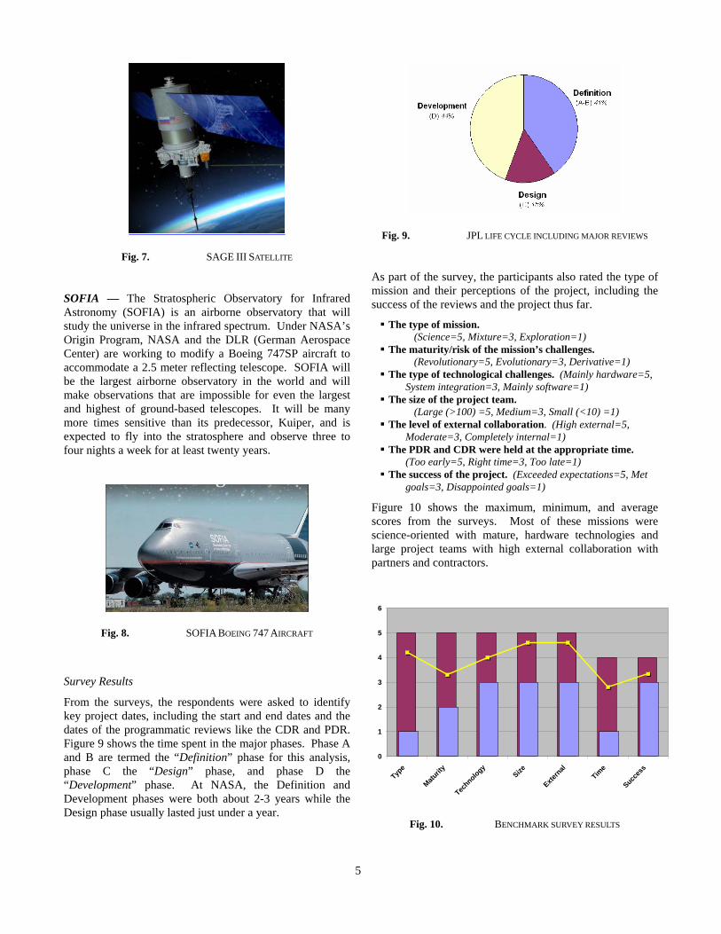
SAGE — Stratospheric Aerosol and Gas Experiment (SAGE) III is a satellite-borne instrument with a role in the Earth Observing System to provide global, long-term measurements of key components of the Earth’s atmosphere. It has become increasingly clear that human activities have created atmospheric issues including global warming and declining levels of ozone. The most important of these are the vertical distribution of aerosols and ozone. In addition, SAGE will provide unique measurements of temperature and profiles of trace gases such as water vapor and nitrogen dioxide.
5
Fig. 7. SAGE III SATELLITE
SOFIA — The Stratospheric Observatory for Infrared Astronomy (SOFIA) is an airborne observatory that will study the universe in the infrared spectrum. Under NASA’s Origin Program, NASA and the DLR (German Aerospace Center) are working to modify a Boeing 747SP aircraft to accommodate a 2.5 meter reflecting telescope. SOFIA will be the largest airborne observatory in the world and will make observations that are impossible for even the largest and highest of ground-based telescopes. It will be many more times sensitive than its predecessor, Kuiper, and is expected to fly into the stratosphere and observe three to four nights a week for at least twenty years.
Fig. 8. SOFIA BOEING 747 AIRCRAFT
Survey Results
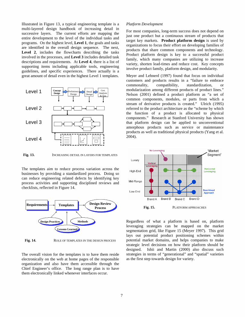
From the surveys, the respondents were asked to identify key project dates, including the start and end dates and the dates of the programmatic reviews like the CDR and PDR. Figure 9 shows the time spent in the major phases. Phase A and B are termed the “Definition” phase for this analysis, phase C the “Design” phase, and phase D the “Development” phase. At NASA, the Definition and Development phases were both about 2-3 years while the Design phase usually lasted just under a year.
Fig. 9. JPL LIFE CYCLE INCLUDING MAJOR REVIEWS
As part of the survey, the participants also rated the type of mission and their perceptions of the project, including the success of the reviews and the project thus far.
The type of mission. (Science=5, Mixture=3, Exploration=1)
The maturity/risk of the mission’s challenges. (Revolutionary=5, Evolutionary=3, Derivative=1)
The type of technological challenges. (Mainly hardware=5, System integration=3, Mainly software=1)
The size of the project team. (Large (>100) =5, Medium=3, Small (<10) =1)
The level of external collaboration. (High external=5, Moderate=3, Completely internal=1)
The PDR and CDR were held at the appropriate time. (Too early=5, Right time=3, Too late=1)
The success of the project. (Exceeded expectations=5, Met goals=3, Disappointed goals=1)
Figure 10 shows the maximum, minimum, and average scores from the surveys. Most of these missions were science-oriented with mature, hardware technologies and large project teams with high external collaboration with partners and contractors.
0
1
2
3
4
5
6
Type
Maturit
y
Technology
Size
Extern
alTim
e
Succes
s
Fig. 10. BENCHMARK SURVEY RESULTS

6
A product definition tool, the Project Priority Matrix (Ishii 2004) forces a team to agree on the goals of a project upfront. The matrix begins by identifying constrained factor (e.g., hard limit on time-to-market, hard budget/cost target, a new level of features/functions). Next, the priority to be optimized is determined (e.g., quicker time-to-market, minimize cost, maximize features/functions). The remaining item must then be accepted. Figure 11 shows the cumulative priorities identified by the missions benchmarked.
Con
stra
in
Opt
imiz
e
Acc
ept
Feature 4 1 1
Cost 2 3 1
Time 1 2 2
Fig. 11. AGGREGATED PROJECT PRIORITY RESULTS
Most missions were rated as feature constrained, cost optimize, and time accept, though most everyone surveyed said it was really constrained by all three, with one person even prioritizing their mission as such.
Interview Comments — In addition to general insight on development at NASA, the participants described the key system-level PDR and CDR reviews they experienced for their projects. They generally believed the reviews were held at appropriate times. For the most part, the teams were more content with the PDR review. Usually the documentation was good and the project was on-time at that milestone. However, they found it difficult to assess the proper time to have the CDR, particularly as the assumption of the serial nature of development did not factor the pace of various components.
In particular, the effectiveness of reviews on the lower sub-system and instrument levels were cited to be a major issue. Both the PDR and CDR failed to capture instrument and sub-system level issues that later surfaced. The teams tried to incorporate more technical “table top” subsystem reviews prior to the main meetings, and some would even insist on having delta-CDR reviews for each instrument. Though the reviewers were technically strong, there was not enough time to thoroughly and sufficiently assess the technical issues at these reviews. These results were consistent with previous studies (Chao et al. 2004) that identified Project QFD (Chao and Ishii 2004b) as an aid in product definition and resource allocation.
Other issues were related to the programmatic and even political nature of the reviews. Many of the participants
believed that the reviewers often focused their energy on issues that were not as relevant to the success of the mission. Some even cited competitive resentment by members whose projects were not chosen instead or those that didn’t understand some of the technical interactions and even international issues.
3. DISCUSSION AND RECOMMENDATIONS
Comparison with industry practices
Industry organizations face some common challenges as NASA. Though the range in the complexity and cost of the products designed in their new product development may vary greatly, some organizations have similar high reliability and complexity but low volume issues. In response, many organizations have implemented a number of product development practices which are relevant to non-commercial domains. Stanford University’s collaboration with industry partners such as GE, ABB, Toshiba, Sun, and GM as well as other government laboratories like the Stanford Linear Accelerator Center (SLAC) has allowed extensive survey and benchmark of their practices, including the use of process templates, platform design, and portfolio management, which will be detailed here.
Engineering Process Templates
Used in organizations like aerospace and aircraft engine companies, an engineering process template defines the key engineering steps and activities required to design and verify a part, component, module, or system such that it meets the specified technical requirements. It is a roadmap of what needs to be done. A series of templates can connect the high level New Product Introduction (NPI) guide with detailed level Design Practices. It is not, however, a set of detailed instructions on “how to do it.”
NPI / EDC GUIDE(High Level Program Details)
Roadmap
Strategy
Tactics
Low
High
Alti
tude
Engineering Process Templates(Specific Process Details)
Technical Resources(In-depth Technical Details)- Design Practices- Lessons Learned- Technical Memorandums- Etc.
Fig. 12. ENGINEERING DESIGN ARCHITECTURE
7
Illustrated in Figure 13, a typical engineering template is a multi-layered design handbook of increasing detail in successive layers. The current efforts are mapping the entire development to the level of the individual tasks and programs. On the highest level, Level 1, the goals and tasks are identified in the overall design sequence. The next, Level 2, includes the flowcharts describing the tasks involved in the processes, and Level 3 includes detailed task descriptions and requirements. At Level 4, there is a list of supporting items including applicable tools, engineering guidelines, and specific experiences. There actually is a great amount of detail even in the highest Level 1 templates.
PreliminaryDesign
DetailDesign
Cert.Analysis& Test
ConceptDesign
PreliminaryDesign
PreliminaryDesign
DetailDesignDetailDesign
Cert.Analysis& Test
Cert.Analysis& Test
ConceptDesignLevel 1
Level 2
Level 3
Level 4
Fig. 13. INCREASING DETAIL IN LAYERS FOR TEMPLATES
The templates aim to reduce process variation across the businesses by providing a standardized process. Doing so can reduce engineering related defects by identifying key process activities and supporting disciplined reviews and checklists, reflected in Figure 14.
Requirements Templates Design ReviewProcess
Design Practices Methods
Lessons Learned
Fig. 14. ROLE OF TEMPLATES IN THE DESIGN PROCESS
The overall vision for the templates is to have them reside electronically on the web at home pages of the responsible organization and also have them accessible through the Chief Engineer’s office. The long range plan is to have them electronically linked whenever interfaces occur.
Platform Development
For most companies, long-term success does not depend on just one product but a continuous stream of products that target key markets. Product platform design is used by organizations to focus their effort on developing families of products that share common components and technology. Product platform design is key to a successful product family, which many companies are utilizing to increase variety, shorten lead-times and reduce cost. Key concepts involve product family, platform design, and modularity.
Meyer and Lehnerd (1997) found that focus on individual customers and products results in a “failure to embrace commonality, compatibility, standardization, or modularization among different products of product lines.” Nelson (2001) defined a product platform as “a set of common components, modules, or parts from which a stream of derivative products is created.” Ulrich (1995) referred to the product architecture as the “scheme by which the function of a product is allocated to physical components.” Research at Stanford University has shown that platform design can be applied to unconventional amorphous products such as service or maintenance products as well as traditional physical products (Yang et al. 2004).
Fig. 15. PLATFORM APPROACHES
Regardless of what a platform is based on, platform leveraging strategies can be mapped on the market segmentation grid, like Figure 15 (Meyer 1997). This grid lays out potential product positioning schemes within potential market domains, and helps companies to make strategic level decisions on how their platform should be designed. Ishii and Martin (2000) also discuss such strategies in terms of “generational” and “spatial” varieties as the first step towards design for variety.
8
Revenue
Time Time
Investment
I->L MRDO LP
Investment
I->L MR
Revenue
DO LP
Investment
TimeI->L MR
Revenue
DO LP
Revenue
Time Time
Investment
I->L MRDO LP
Investment
I->L MR
Revenue
DO LP
Investment
TimeI->L MR
Revenue
DO LP
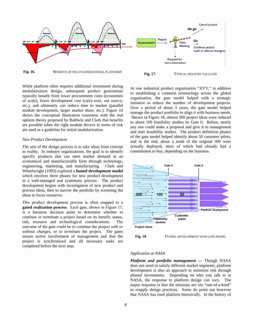
Fig. 16. BENEFITS OF MULTI-GENERATIONAL PLATFORMS
While platform often requires additional investment during modularization design, subsequent product generations typically benefit from lower procurement costs (economies of scale), lower development cost (carry-over, out source, etc.), and ultimately can reduce time to market (parallel module development, larger market share, etc.). Figure 16 shows the conceptual illustration consistent with the real options theory proposed by Baldwin and Clark that benefits are possible when the right module drivers in terms of risk are used as a guideline for initial modularization.
New Product Development
The aim of the design process is to take ideas from concept to reality. In industry organizations, the goal is to identify specific products that can meet market demand in an economical and manufacturable form through technology, engineering, marketing, and manufacturing. Clark and Wheelwright (1993) explored a funnel development model which involves three phases for new product development in a well-managed and systematic process. The product development begins with investigation of new product and process ideas, then to narrow the portfolio by screening the ideas to focus resources.
This product development process is often mapped to a gated realization process. Each gate, shown in Figure 17, is a business decision point to determine whether to continue or terminate a project based on its benefit, status, risk, resource and technological considerations. The outcome of the gate could be to continue the project with or without changes, or to terminate the project. The gates ensure active involvement of management and that the project is synchronized and all necessary tasks are completed before the next step.
Fig. 17. TYPICAL INDUSTRY TOLLGATE
At one industrial product organization “XYY,” in addition to establishing a common terminology across the global organization, the gate model helped with a strategic initiative to reduce the number of development projects. Over a period of about 3 years, the gate model helped manage the product portfolio to align it with business needs. Shown in Figure 18, almost 300 project ideas were reduced to about 100 feasibility studies by Gate 0. Before, nearly any one could make a proposal and give it to management and start feasibility studies. The product definition phases of the gate model helped identify about 50 customer pilots, and in the end, about a tenth of the original 300 were actually deployed, most of which had already had a commitment to buy, depending on the business.
Fig. 18. FUNNEL DEVELOPMENT WITH GATE MODEL
Application at NASA
Platform and portfolio management — Though NASA does not need to satisfy different market segments, platform development is also an approach to minimize risk through phased investments. Depending on who you talk to at NASA, the response to platform design can vary. The major response is that the missions are too “one-of-a-kind” to reapply design practices. Some do point out however that NASA has used platform historically. In the history of

9
JPL, a number of platforms, including Explorer, Ranger, and Mariner have been developed. Current missions are platform oriented in that they use the same launch capabilities, less so in terms of the mission design.
Usually the generation of these platforms involved only the modification of one sub-system or minor upgrades. The heritage of these missions is more in the concept rather than the execution. Perhaps one or two sub-system hardware will be continued. Generally speaking, these considerations are done from a cost-competitive environment point-of-view in identification of the cheapest way to execute the mission consistent with space science priorities. If the sub-system can be purchased off-the-shelf, then so be it. The mission attempt to minimize the insertion of new technology while meeting the requirements. The issue is that most commercial parts can not be used as they can not meet specifications such as radiation and vibration involved in space flight.
The challenge is in understanding what is being inherited when hardware is being re-used. The design heritage is a part of the verification and validation program as well. Part of the PDR and CDR process, for example, is to review the design heritage. Though NASA has worked to capture the lessons learned from failure, through reference databases like the Lessons Learned Information System, a reference database of different failures, defects, and other events from NASA projects and missions, design practices and process templates do not seem to be used at all. Records that are available, such as requirements documents and specifications, are often difficult to find and some times only archived with paper copies, and not even accessible electronically. To better understand the heritage, not only does the engineering process need to be captured better through process templates, best practices, and lessons learned, accessibility to this knowledge must be improved.
With directed funding, NASA management can more closely specify project portfolio direction and coverage. However, at NASA now, the development of new missions can seem like a zero-sum game. New projects and proposals can be competitive with the need to go through several stages of approvals and proposals of Notice of Intents (NOI’s). A competitive environment is not necessarily a bad thing, as long as the competition is fair and the benchmarks or metrics for evaluation reflect the overall organization goals. Because these missions and projects are often developed as such, there is not always a strong synergy between projects. Rather than have top-down push of projects, researchers in NASA must competitively apply for funding, some times competing externally with industry organizations or university laboratories. When grants are given, NASA has less control over the quality and direction of the research unless a NASA co-investigator is involved. If the portfolio could be better managed by the organization and a platform approach taken, the organization could ensure better science coverage.
The response of most NASA personnel to the suggestion of more platform development concepts and a portfolio management method like funnel development was positive. Many were familiar with the concepts already and didn’t understand why NASA hadn’t taken such approaches. Though some felt there would be challenges, it was more in overcoming the culture than the technical challenges.
Process management — As a comparison, the time spent in each phase was compared with a similar, large-scale effort spent a global, industrial products organization. Figure 19 shows the time spent in each phase at NASA compared with an industrial products and services organization, “XYY.” This chart shows the extreme schedule pressure between the PDR and CDR for NASA missions. For this reason, it is extremely important that the product and mission definition to be complete.
0%
5%
10%
15%
20%
25%
30%
35%
40%
45%
50%
Definition Design Development
NASAXYY
Fig. 19. COMPARISON OF PHASES OF DEVELOPMENT
One key difference to note is that some times in the NASA life-cycle, the Development phase includes the operation of the mission while industry gate approaches do not include the consumer or customer usage in its mapping. In industry experience, case studies at XYY revealed that hardware projects spent more time in definition phase while software times put more time into the design phase because of dynamic, changing requirements (Chao and Ishii 2004a). At a third organization, the allocation between the phases varied greatly. In this gated organization, the Definition phase is not really measured as it is the “fuzzy front end” while the Design phase is about 6 months and the Development phase from launch to certification ran about 24-28 months.
In the context of Figure 19, one project manager believed that 30% of the design should be completed before the PDR and that 20-25% of the total effort in terms of costs should be before development. Due to recent changes in the organization of the NASA financial system, there was some

10
chaos and uncertainty with budget. However, this is also an opportunity to improve the system. Currently, the view is too many projects are funded partially, rather than choosing the right projects and funding them fully. One project manager even suggested a further tightening and focus on the bottom line, even hiring professional costing experts. If projects in the portfolio are overrun by more than 15%, then the managers should go to a cancellation view
Rapid Spacecraft Development Office — One NASA group which is taking a modular/platform development approach is the Rapid Spacecraft Development Office (RSDO). The RSDO is a flight mission support office at the Goddard Space Flight Center. The RSDO is a Government-wide agent for the rapid procurement of pre-qualified domestic and foreign commercial spacecraft. Major missions that have developed via RSDO delivery orders include QuickToms, QuickScat, ICESat, Coriolis, SWIFT, and GLAST. The RSDO significantly reduces the spacecraft procurement time and mission implementation risk. The RSDO spacecraft are made available under firm fixed price core contracts and are purchased via Delivery Orders. Spacecraft design studies can be particularly useful to find the best payload accommodation or is in need of solidifying mission and interface requirements prior to release of a spacecraft contract.
The RSDO maintains a catalog of the available spacecraft. The catalog currently includes 21 spacecraft from 8 aerospace companies, modifiable to meet specific requirements. Collectively they have a payload mass and power capability ranging from 10 kg/10 W to approximately 800 kg/800 W. All cataloged spacecraft designs must have been built-tested and, mated- and interface-tested with a launch vehicle. Currently, all catalog spacecraft have successfully performed on orbit. The catalog includes pre-priced options for design capability and services enhancements. The spacecraft procurement can be completed in 60 to 90 days. All spacecraft delivery orders include full prime contractor services including program and quality management, systems engineering, spacecraft build and test, interface integration and ICD development, payload integration and test support, observatory testing, delivery to launch site, launch vehicle integration support, and on-orbit checkout. In addition to a spacecraft, the contract provides for the procurement of payload accommodation studies, mission operations support, launch vehicle/launch services, sustaining engineering, and spacecraft components/subsystems.
4. CONCLUSIONS
Since the Apollo program that exemplified the extraordinary technical and engineering ability of NASA, the organization has kept the same “can-do” culture and perhaps been resistant to modify it at all. In the 1990’s,
NASA Chief Daniel S. Golden hoped to achieve quality management approaches such as those advocated by W. Edwards Deming. The agency of “first-of-a-kind” challenges was critical of the radical changes proposed. The change of NASA Administrators as well as the decreasing budgets resulted in what the Columbia Accident Investigation Board (CAIB) referred to as a phase of “continuous turmoil.” With the “faster, better, cheaper” approach and the downsizing of the agency, NASA was forced to remove the “checks and balances” and change its engineering practices. For example, historically, NASA has employed two engineering teams, one contractor and one government, to cross check each other and prevent catastrophic errors. Though recognized to be expensive, it has been called the “single most important factor” in mission success. However, recent budget cuts meant this could not be done as often.
Structured practices observed and developed in industry and academia are not often well-accepted by other organizations which didn’t develop them “in-house.” The response is often like that expressed by the NASA CAIB saying it is “arguable whether these business principles can readily be applied to a government agency operating under civil service rules and in a politicized environment.” Just as Frederick Taylor’s principles were some times misused by employers in the 19th century to extract more work from employees at less pay, quality and reliability principles must be appropriately developed and applied with considerations of the government bureaucracies.
Certainly, the goal of industry organizations and NASA is not perfectly aligned. The goal of NASA is and should be to promote scientific research and explore the leading edge, rather than to turn a profit. However, initiatives taken in industry are not always geared simply towards profits at the cost of quality, reliability, and efficiency. The success of new product development initiatives and platform and portfolio management methods have been proven in industry, but at the same time, they must be properly modified and customized to the problems, organizational structure, and technology unique to NASA. In addition, the motivation of these methods must be clarified. Efficiency is not more important than safety; rather, an efficient process allows more effort and resources to be spent on such critical issues.
This report described a perspective of development life-cycle and even development culture observed at NASA through interviews and surveys of missions, including current projects such as Aura, CALIPSO, Kepler, SAGE and SOFIA. NASA’s life-cycle model, like the gate approaches, is used to understand and mitigate risk and synchronize project work. Being a government agency, NASA deals with unique bureaucracies unlike those in industry. In response to that, most managers and engineers don’t want to add any more levels of complexity when not required. Because of NASA’s “one-of-a-kind” and “first-of-a-kind” viewpoint on its developments, the agency has

11
not fully embraced some techniques proven in industry such as the use of process templates, platform development, and portfolio management. With better understanding of not only the execution but motivation for the current development life-cycle, both NASA and other organizations can better improve and error-proof their design process. By having a strong and consistent development process, both the process and the system reviewed can be better understood. An organization can then more effectively and efficiently implement and even error-proof design.
ACKNOWLEDGEMENTS
We sincerely appreciate the assistance of Francesca Barrientos, Matt Bohm, and Mike Van Wie, and the cooperation of John Baker, Obie Bradley, Ted Brown, John Cox, Debra Dajon, Dennis Dillman, Pam Empert, Ron Johnson, Paul Keas, Gregory Smith, David Swenson, Kathy Tulua, Larry Webster, and Chris Wiltsee. Thanks also to Gene Wiggs and Klaus-Dieter Hildebrandt. Special thanks to Engineering for Complex Systems Program at NASA Ames Research Center and Mission Critical Technologies.
REFERENCES
[1] Baldwin, C.Y., and Clark, K.B., Design Rules, The Power of Modularity, Vol. I, The MIT Press, Cambridge, MA, 2000.
[2] Chao, L.P., and Ishii, K., 2004a, “Product Platform Design and the Gate Model: Lessons from Industry Case Studies.” Proceedings of ASME International Mechanical Engineering Congress and Exposition: DFM, Anaheim, CA.
[3] Chao, L.P., and Ishii, K., 2004b, "Design Process Error-Proofing: Project Quality Function Deployment," Proceedings of the ASME Design Engineering Technical Conference: DFM, Salt Lake City, UT.
[4] Chao, L.P., Tumer, I., and Ishii, K., 2004, "Design Process Error-Proofing: Engineering Peer Review Lessons from NASA," Proceedings of the ASME Design Engineering Technical Conference, Salt Lake City, UT.
[5] Clark, K.B., and Wheelwright, S.C., 1993, Managing New Product and Process Development: Text and Cases, The Free Press, New York.
[6] Gehman, H.W., et. al., 2003, “Columbia Accident Investigation Board Report,” National Aeronautics and Space Administration, Volume I, August.
[7] Huber, T.E., (ed.), 1992, “The NASA Mission Design Process.” NASA Engineering Management Council. 22 Dec. 1992.
[8] Iannota, B., 2002, “Seeing stars with SOFIA,” Aerospace America, American Institute of Aeronautics and Astronautics, June.
[9] Ishii, K., (ed.), 2004, ME317 Design for Manufacturability Course Reader, Stanford University, Stanford, CA.
[10] Martin, M.V., and Ishii, K., 2000, “Design for Variety: A Methodology for Developing Product Platform Architectures,” Proceedings of the ASME DETC: DFM, Baltimore, MD.
[11] Meyer, M.H., and Lehnerd, A.P., 1997, The Power of Product Platforms: Building Value and Cost Leadership, the Free Press, New York, NY.
[12] Meyer, M.H., 1997, “Realize Your Product Lines Through Continuous Platform Renewal,” Research Technology Management, 40(2), pp. 17-28.
[13] Nelson, S.A. II, Parkinson, M.B., and Papalambros, P.Y., 2001, “Multicriteria Optimization in Product Platform Design,” Journal of Mechanical Design, Vol. 123, No. 2, pp. 199-204.
[14] Quinn, J., 1994, “Flight P/FR’s and the Design Review Process.” Jet Propulsion Laboratory, D-11381, National Aeronautics and Space Administration.
[15] Robertson, D., and Ulrich, K., 1998, “Planning for product platforms,” Sloan Management Review: 19-31.
[16] Rose, J., 2003, “Project Reviews (D-10401), Rev. B.” JPL Rules! DocID 35163, National Aeronautics and Space Administration, April 23.
[17] Simpson, T.W., 1998, “A Concept Exploration Method for Product Family Design,” Ph.D. Dissertation, George W. Woodruff School of Mechanical Engineering, Georgia Institute of Technology, Atlanta, GA.
[18] Ulrich, K., 1995, “The role of product architecture in the manufacturing firm,” Research Policy, 24 (3): 419-440.
[19] Vaughan, D., 1996, The Challenger Launch Decision, The University of Chicago Press, Chicago.
[20] Yang, T., Beiter, K., and Ishii, K., 2004, “Product Platform Development: An approach for products in the conceptual stages of design.” Proceedings of ASME International Mechanical Engineering Congress and Exposition: DFM, Anaheim, CA.
[21] CNN.com, “Investigator worried NASA culture won’t change.”
http://www.cnn.com/2003/TECH/space/08/01/sprj.colu.shuttle.investigation.ap/index.html
[22] CNN.com, “NASA promises to break culture of silence”
http://www.cnn.com/2003/TECH/space/07/27/sprj.colu.nasa.culture.ap/index.html
[23] CNN.com, “NASA shakes up shuttle management.” http://www.cnn.com/2003/TECH/space/07/03/nasa.shakeup.ap/index.html
[A] CoMITS http://m-20.arc.nasa.gov/pls/cms_user/about
[B] Aura

12
http://eos-chem.gsfc.nasa.gov [C] CALIPSO
http://www-calipso.larc.nasa.gov [D] Kepler
http://www.kepler.arc.nasa.gov [E] SAGE
http://www-sage3.larc.nasa.gov/ [F] SOFIA
http://sofia-usra.arc.nasa.gov/ [G] Lessons Learned Information System
http://llis.nasa.gov/llis/llis/llis.html [H] Rapid Space Development Office
http://rsdo.gsfc.nasa.gov/
BIOGRAPHY
Lawrence Chao earned his BS in Mechanical Engineering at the Massachusetts Institute of Technology and MS in
Mechanical Engineering Design at Stanford University. He has worked at and with organizations including General Electric, ABB, NASA, and General Motors. He is currently a Ph.D. candidate and research assistant with the Manufacturing Modeling Laboratory of
Stanford University's Department of Mechanical Engineering Design Division under Professor Kosuke Ishii. His research focus is on "design process error-proofing" developing tools, methods, and strategies to understand, predict, and prevent product development errors.
Dr. Irem Y. Tumer has been with the Computational Sciences Division at NASA Ames Research Center since
1998. Her research interests focus on formal design methods, risk-based design, risk mitigation, and failure analysis and fault detection systems, with the overall goal to improve the state-of-the-art in designing reliable and robust NASA mission-enabling systems. She is a Level 3 project manager, managing
projects ranging from risk characterization and optimization to model based risk analysis. She received her PhD in Mechanical Systems & Design from The University of Texas at Austin.
Dr. Kosuke Ishii earned his BSME at Sophia University, Tokyo, MSME at Stanford University, and Masters in Control Engineering at Tokyo Institute of Technology. After serving Toshiba Corporation as a design engineer, he returned to Stanford and completed his PhD in Mechanical Design. He currently holds the rank of
full professor at Stanford University, serves as the director of the Manufacturing Modeling Laboratory, and focuses his research on structured product development methods, commonly known as "Design for X."