designing gear in catia v5
TRANSCRIPT

DESIGNING GEAR IN CATIA V5 Author’s Note: This is step by step guide how to create gear using CATIA. I'm not CATIA expert. Someone might find that CATIA doesn't have much with TCP/IP and FreeBSD. I coulnd't find much about gear design using GOOGLE or YAHOO. Since I enjoy learing and practicing what I learn, I also enjoy s haring that with others (often seen on overnet/edonkey: please share :) don't be selfish. Here is step by step guide how to make spur gear using CATIA. Note that this was inspired by documen t I have found at website www.piovision.com (credits go to t he unknown designer). But let's start. This document assumes that you hav e basic CATIA experience. Also, this document assumes that you know basic spur gear geometry. Here is excellent document from www.bostongear.com in case you are not familiar. Some basic notations : rb - base cylinder radius r - pitch circle radius rk - outside circle radius rf - root radius a - pressure angle (20deg) m - modulo (in our example 20) m=p/3.14159 where p is circular pitch 2r=m*z z - number of teeth (in our example 20) When you start CATIA, go to TOOLS->OPTIONS->Infrastructure-> Part Infrastructure and in Display select Paramteres and Relations .

Then in Options->General in Parameters and Measures select With value and With formula in Parameters Tree View .
Now it is time to go to Generative Shape Design :
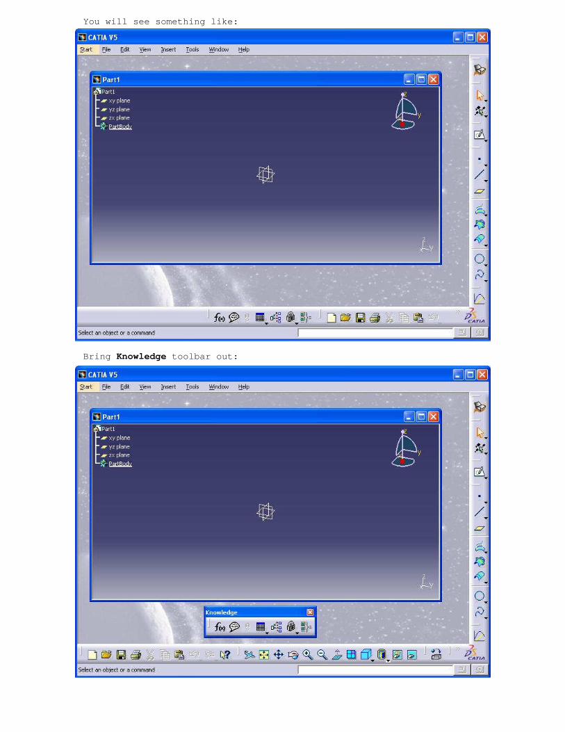
You will see something like:
Bring Knowledge toolbar out:

Then by clicking on arrow pointed down near table i con: Fog and f(x) are two most important things you will use for Gea r Design:
Now it is time to enter some basic parameters that define gear This is done by clicking at f(x) icon:

And then when you see dialog box: Formulas: Part1 fist select Parameter type (real, length or angle) click new Parameter of type and then edit value. You can do t his until all parameters are entered.
When you enter parameters it is time to enter some formulas. For, r, rb, rk and rf we enter formulas by naming t hem and by clicking Add Formula. Formula editor will appear:

After typing all formulas and expanding specificati on tree you will see something like this:
It is time to add laws that will define our involut e. Click on fog icon, name law x add parameters, t and x select the ir types and add law:

Same should be done for y. This law will help us to create points that define spline for our involute. Involut e is line that is trajectory of point belonging to line that is always tangent to base gear cylinder. It is used for tooth profile. If gears had profiles formed by straight lines they wouldn't work.
After expanding specification tree you should be ab le to see something like this:

Now it is time to start creating our points for inv olute spline. Click on point icon, select xy plane for support an d when asked to enter H and V cordinates right button click shou ld bring menu where you should chose edit formula:
You will be prompted by edit formula dialog. Type i n: Relations\x .Evaluate(0)
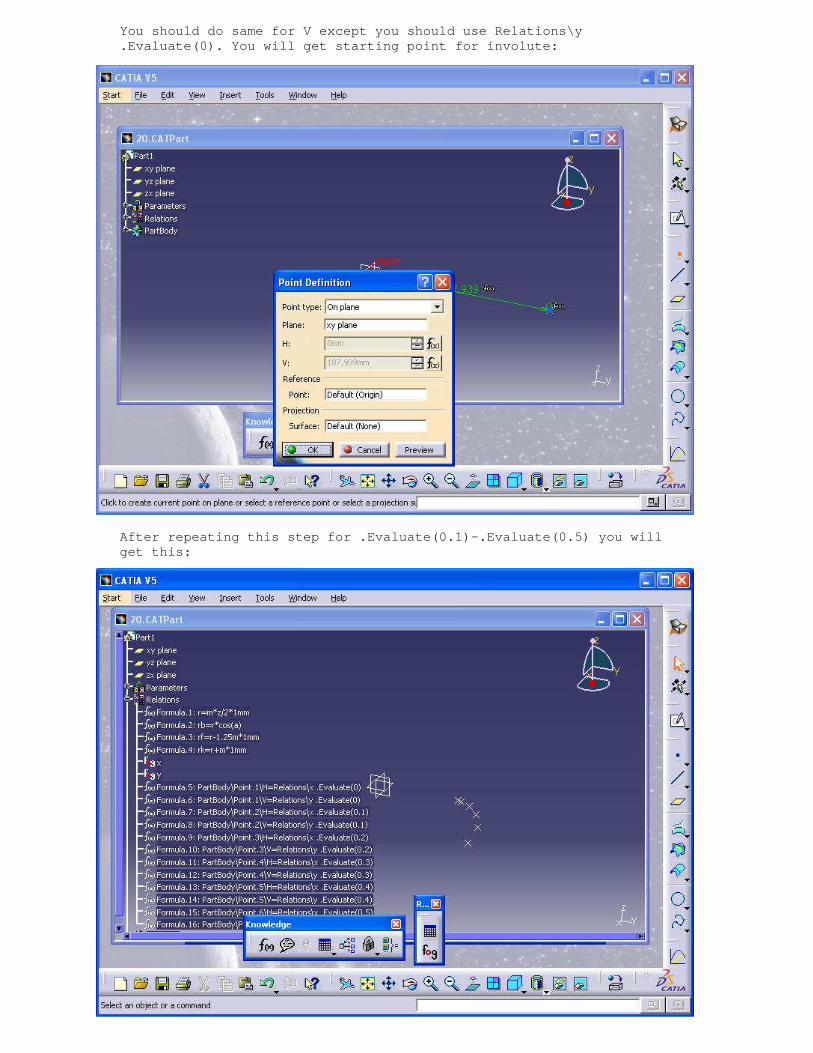
You should do same for V except you should use Rela tions\y .Evaluate(0). You will get starting point for invol ute:
After repeating this step for .Evaluate(0.1)-.Evalu ate(0.5) you will get this:
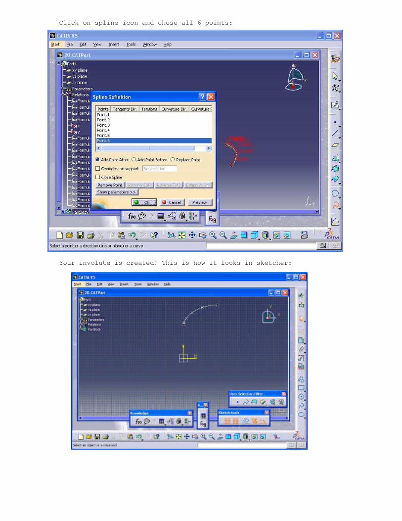
Click on spline icon and chose all 6 points:
Your involute is created! This is how it looks in s ketcher:

From this point everything is more or less simple. Create base cirle by clicking on cirle icon. Right click on radius and chose rb from formula edi tor:
Now it is time to extrapolate our involute. For len gth also right click and chose formula (rb-rf)*1.5

You can use View-> zoom and pan to see what actuall y you are doing. Create plane. Use formula: inv(360/z)/4. You will g et -4.5deg angle offset from ZY plane.
After this create rf circle and from insert menu us e corner to create corner. Corner dialog will appear:

This is what you should get:
Now use trim and result should be:

It is time for symmetry. Tooth starts to get shape:
Create rk circle and use trims to get tooth shape:
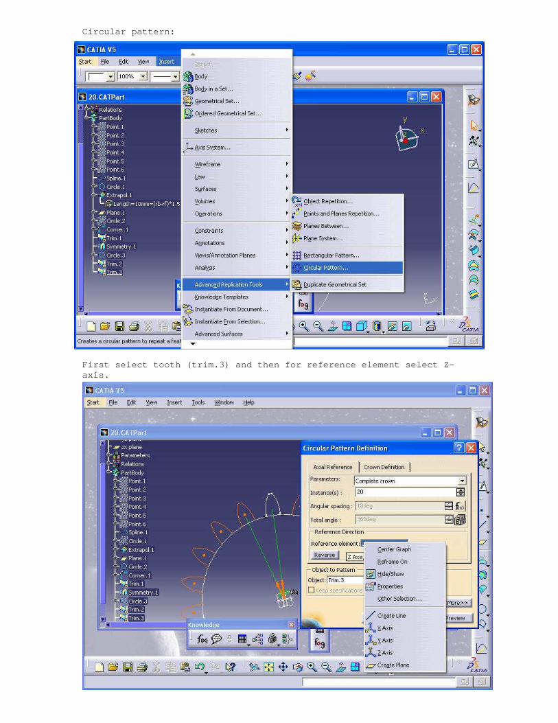
Circular pattern:
First select tooth (trim.3) and then for reference element select Z-axis.

Gear is almost done now it is time for joining all teeth: Turn off check manifold and check consistency:
Apply one more trim and here is our gear in normal plane:

So in case that you want all process as. CATPart please send me the mail I will send you the. CATPart for this gear