designing solar pv systems ( utility scale)
TRANSCRIPT

Designing Solar PV Systems ( Utility Scale)

Module 1 : Solar Technology Basics
Module 2: Solar Photo Voltaic Module Technologies
Module 3: Designing Solar PV Systems (Rooftops)
Module 4: Designing Solar PV Systems (Utility Scale )
Module 5: Financial Analysis
Module 6: DPR (Detailed Project Report) & EPC
Module 7: The present Solar industry scenario and the future

THE PLANT
Technology Selection
Layout and Shading
Design Optimization
Electrical Design
The Plant Design
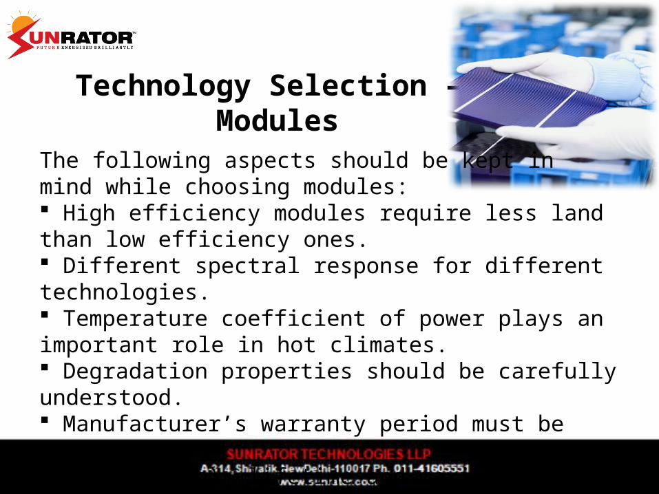
Technology Selection – Modules
The following aspects should be kept in mind while choosing modules: High efficiency modules require less land than low efficiency ones. Different spectral response for different technologies. Temperature coefficient of power plays an important role in hot climates. Degradation properties should be carefully understood. Manufacturer’s warranty period must be looked upon. Cost (Rs/Wp), lifetime and maximum system voltage should be considered.

Technology Selection – Inverters
Size plays a very important role for the inverter connection concept. For utility-scale power plants, central inverters are preferred.
High efficiency A wide MPP rangeThe grid code which affects the inverter sizing and technology, is required for controlling the reactive power.

Technology Selection – Inverters (contd.)
Inverters with high reliability has low downtime including low maintenance and repair costs.
For different module specification, string or multi-string inverters are recommended for minimizing the mismatch loses.
For sites with different shading conditions or orientations, string inverters are more suitable.
Criteria like plant monitoring, data logging and remote control must be taken into account.
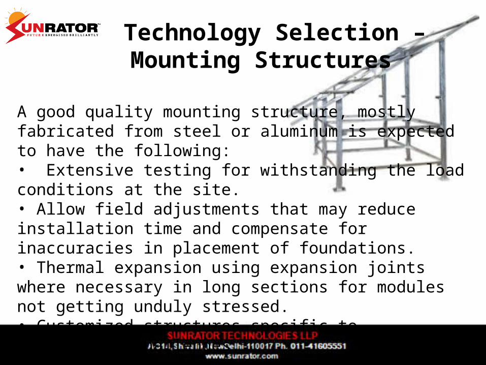
Technology Selection – Mounting Structures
A good quality mounting structure, mostly fabricated from steel or aluminum is expected to have the following:• Extensive testing for withstanding the load conditions at the site.• Allow field adjustments that may reduce installation time and compensate for inaccuracies in placement of foundations. • Thermal expansion using expansion joints where necessary in long sections for modules not getting unduly stressed.• Customized structures specific to engineering challenges.

Layout and Shading – Tilt Angle & Orientation
To generate the maximum energy, the modules should be tilted at an angle so that the sun hits it at a perpendicular angle at all times.
Optimum orientation – True SouthEast orientation-Receive sunlight only before noon.West orientation-Receive sunlight only after noon.

Layout and Shading – Inter Row Spacing
α, the shading limit angle is the solar elevation angle beyond which there is no inter-row shading on the modules. If the elevation of the sun is lower than α then a proportion of the module will be shaded. Alongside, there will be an associated loss in energy yield. The shading limit angle may be reduced either by reducing the tilt angle β or increasing the row pitch d.
Image: Schletter Gmbh

Electrical DesignDC System – PV array design
• Maximum number of modules in a string Voc (module) x Nmax < Vmax (Inverter, DC)
• Minimum number of modules in a string Vmpp (module) x Nmin > Vmpp (Inverter, min)
•Voltage Optimization
• Number of Strings

Electrical DesignDC System – Inverter SizingFollowing factors must be considered when sizing an inverter:• The maximum Voc in the coldest daytime temperature must be less than the inverter maximum DC input voltage.• The inverter must be able to safely withstand the maximum array current.•The minimum Voc in the hottest daytime temperature must be greater than the inverter DC turn-off voltage.• The maximum inverter DC current must be greater than the PV array/s current.• The inverter MPP range must include PV array MPP points at different temperatures.

Electrical DesignDC System – Cable Selection and Sizing
Following factors must be considered when sizing cables:
• The cable voltage rating
• The current carrying capacity of the cable
• The minimization of cable losses

Electrical DesignAC System – AC Cabling
Following factors must be considered when designing the cabling:
• The cable must be rated for the maximum expected voltage.• The conductor should be able to pass the operating and short circuit currents safely.• The conductor should be sized appropriately to ensure that losses produced by the cable are within acceptable limits.• The conductors should be sized to avoid voltage drop outside statutory limits and equipment performance.• Insulation should be adequate for the environment of installation.• Either copper or aluminium conductors should be chosen.• Number of cores (single or multiple) should be chosen accordingly.• Earthing should be properly designed.

Electrical DesignAC System – AC Switchgear
Considerations must be given to switchgears which are :
• In accordance with IEC and national standards.• Options for secured off/ earth positions.• Rated for operational, short circuit currents and correct operational voltage.• Remote switching capability for HV switchgear.• Suitable earthing.

Electrical DesignAC System – Transformer selection and sizing
Transformers are required for providing suitable voltage levels for transmission across the site and export to the grid.Transformers can also loose energy through magnetising currents in the
core. These losses are known as iron and cooper losses. Minimising the losses will increase the energy supplied to the grid and thus enhance the revenue of the power plant.

Electrical DesignAC System – Substation
Metering: To measure the export of power, tariff metering is required. The meter provided at the substation or at the point of connection to the grid has inputs from the current as well as voltage transformer.
Data Monitoring / SCADA
Auxiliary Equipments: LV power supplies, diesel generators, lighting, water supplies, drainage, safety systems etc.

Electrical DesignAC System – Lighting and Surge protection
• Array frame lighting• System earthing (DC conductor earthing)• Inverter earthing• Lightning and surge protection.

Optimizing the system design
• Reducing the system losses for better plant performance.• Balancing annual yield and economic return.• Proper technology selection and prior simulation for better analysis and optimization.• Thorough technical due diligence for mitigating performance issues.
