designing with gabions & mattresses - leading uk … walling_design_manual.pdfdesigning of river...
TRANSCRIPT

Volume 3A Reference Guide for the
Designing of River and Coastal Gabion Protection Works
Designing with Gabions & Mattresses
Registered Office: Unit 5, The Cobden Centre, Folly Brook Road, Emerald Park, Emersons Green, Bristol BS16 7FQEnviromesh is a trading name of Cerana Limited. Registered in England No. 5065615

Contents
CONDITIONS & LIMITATIONS PAGE 1
INTRODUCTION PAGE 2
WHAT ARE GABION AND GABION MATTRESSES? PAGE 3
WELDED MESH GABIONS PAGE 4
WOVEN MESH GABIONS PAGE 5
WOVEN MESH GABION MATTRESSES PAGE 6
FILLING MATERIALS PAGES 7 - 8- Gabions- Gabion Mattresses
DESIGN: MATTRESS PROTECTION PAGE 9
SLOPING REVETMENTS PAGES 10 - 12
STEPPED REVETMENTS & SCOUR PAGES 13 - 18PROTECTION
OUTFALLS PAGES 19 - 20
CHANNEL LININGS AND DROP STRUCTURES PAGES 21 - 24
GROYNES PAGES 25 - 26
SPECIFICATIONS PAGES 27 - 34- woven mesh zinc/PVC coated mattresses- gabion 27 system- welded mesh gabion 39 system - 3mm- welded mesh gabion 39 system - 4mm- welded mesh gabion 39 system - 3/4mm- welded mesh gabion 39 system - 5mm- woven mesh zinc coated gabions- woven mesh zinc/PVC coated gabions

Conditions & Limitations
The copyright, design right or other intellectual property in this guide and the products set out herein shall as between Cerana Limited, trading under the Trade Mark of Enviromesh and any customer or potential customer of Enviromesh be the property of Enviromesh.
This publication is intended as a general overview of the subjects dealt with and is not intended and should not be used as a substitute for taking detailed and specific advice in any specific situation. The recommendation and advice given in this booklet is given withoutliability on the part of Enviromesh or its employees and should not be relied upon for any particular action or inaction.
Enviromesh shall not be liable to compensate any other party for any loss, including any consequential loss, arising out of any inaccuracies in or omissions from this guide.
It is the responsibility of all parties to satisfy themselves that the designs, calculations and specifications set out in proposals submitted by Enviromesh are correct and no responsibility is accepted by Enviromesh for the accuracy of the designs and specificationsincluded in such proposals.
EnviromeshGarner Street Business ParkEtruria Stoke-on-TrentStaffordshireST4 7BH
Tel: 0044 (0) 845 136 0101Fax: 0044 (0) 845 136 0202Email: [email protected]: www.enviromeshgabions.com
1

Introduction
Gabions and gabion mattresses have long been used as a system for erosion protection on inland water courses.
Typical applications are as follows:
Channel liningsBank and bed protectionCulvert headwall inlet and outlet structuresProtection around bridge piersOutfall protectionRiver training worksFish habitats
Similarly gabions and gabion mattresses have been used on coastal protection schemes.
Typical applications are:
Top of the beach protection Sloping revetmentsGabion wallingBeach replenishment
Water is a powerful force and unless the protection schemes are correctly designed, then potential failure can occur.
2
What are Gabion and Gabion Mattresses?
The term gabion, refers to a modular containment system that enables rock, stone or other inert materials to be used as a construction material.
The modules or cages as they are known, are formed of wire mesh fabric panels, jointed to form square or rectangular shaped units. The main difference between a gabion and a gabion mattress is in the ratio of plan area to height:
A gabion is a box shape, where the height is normally between 0.5m and 1.0m.
A gabion mattress is a unit that has a large plan area compared to its height. These are normally supplied in heights of between 0.17m to 0.5m.
The units are pre-assembled in the factory to form a flat pack system.
These flat packs are then supplied to the customer and formed into the final shaped module on site with the necessary lacing wire or ‘C’ rings as required. Each module has to be connected to adjacent modules to form a monolithic structure.
The types of mesh used must be of a non ravelling type such as welded steel wire mesh or hexagonal woven wire mesh and provided with corrosion protection to suit the required exposure conditions.
Although gabion mattresses can be manufactured from a welded mesh, this mesh is not as flexible as that manufactured from double twist hexagonal woven wire. Erosion protection schemes generally require units that are flexible, hence it is recommended that the hexagonal woven wire mesh gabion mattresses are used.
3

Welded Mesh GabionsThese gabions are manufactured from a square mesh, normally of opening size 76.2mm x 76.2mm where the longitudinal wires are welded to the cross wires at there intersection points. This type of fabric manufacture produces a dimensionally stable mesh.
This mesh, produced in panels or rolls, is then cut into the required panel sizes to form the flat pack unit. This is done by clipping the face, rear, side and diaphragm panels (intermediate dividing panels) to the base panel so that they can rotate to be folded flat. The lid may be clipped to the front or back panel or left loose dependant upon the unit size.
Units can be manufactured in any multiple of the mesh size, but are normally supplied as standard sizes to the industry. Welded mesh gabions can be readily modified on site by cutting the mesh back to the next transverse mesh wire.
Welded mesh gabions are available in a number of wire diameters to suit the application or can be manufactured in a combination of mesh-wire specifications to provide economy in supply.
The resultant gabions flexibility is dependant upon the choice of wire diameter.
WELDED MESH GABION OPENED OUT FLAT PACK
GABION FORMED INTO BOX SHAPE ON SITE
4

Woven Mesh GabionsThese gabions are manufactured from a mesh that has a hexagonal opening which is formed by twisting pairs of wire together with one and a half turns (sometimes referred to as triple or double twist).
This type of mesh production is continuous. To form panels, the mesh is guillotined across the weave and the cut ends of the wire are wrapped around a heavier wire to form a selvedge end.
The unit is factory fabricated from one main panel which forms the front, base, rear and lid of the unit with additional panels connected to the base section of the main panel to form the diaphragm and end panels. Dependant upon the manufacturer, the mesh orientation is normally either with the weave horizontal or vertical on the face panel and the connection of the ends and diaphragm to the base is via a spiral wire or pairs of twisted wires, twisted together around the base mesh.
This type of mesh is a flexible mesh as it can articulate about the twists. It is normally manufactured from a 2.7mm wire diameter. The coatings are either galvanised only, galvanised and PVC coated or galvanised and HDPE coated. The dimension between the twists is a nominal 80mm.
HEXAGONAL MESH GABION OPENED OUT FLAT PACK
GABION FORMED INTO BOX SHAPE ON SITE
5

Woven Mesh Gabion MattressesThese gabions are manufactured from a mesh that has a hexagonal opening which is formed by twisting pairs of wires together with one and a half turns (sometimes referred to as triple or double twist).
This type of mesh production is continuous. To form panels, the mesh is guillotined across the weave and the cut ends of the wire are wrapped around a heavier wire to form a selvedge end.
The unit is factory fabricated from one main panel which forms the front, base, rear of the unit with additional panels connected to the base section of the main panel to form the diaphragms. The mesh orientation is normally with the weave running along the length of the unit. The lid is supplied as a separate panel.
This type of mesh is a flexible mesh as it can articulate about the twists. It is normally manufactured from a 2.0mm wire diameter woven into a 60mm x 80mm mesh. The coatings are either galvanised only or galvanised and PVC coated. The dimension between the twists is a nominal 60mm.
6
GABION MATTRESS FORMED INTO BOX SHAPE ON SITE
Filling MaterialsGabionsThe selection of rock or stone fill is very important as the performance of gabion structures are dependant not only upon the type of unit but also the infill.
Gabion units generally used as retaining walls along rivers:
Grading of fillGabion fill is normally a graded fill of between 100mm to 200mm in diameter with a nominal 6% of the stone being smaller or larger.The grading can be tightened from 80mm to 150mm providing the control of the grading is good. Stones smaller than the mesh will not be contained by it.The grading is important to ensure that voids within the gabions are minimised, otherwise settlements can occur.
Angularity of fillThe more angular the gabion fill, the better is the interlock of the stone within the gabion. This results in less deformation of the face and reduced internal movement under water flow or wave action. Limiting the movement of contained stone reduces the possibility of abrasion to the protected coating.
Rounded stoneThis has little interlock and results in greater deformation of the face. It also means that the fill within the cell is more fluid and abrasion of the protective coatings to the wire is more probable .
With a rounded fill, heavier guage wires are required to reduce the deformation. It isrecommended to use 4.0mm diameter wire for gabion 27 system and 5.0mm wire diameter for gabion 39 system. It is not recommended to use woven wire gabions manufactured from 2.70mm wire diameter.
Crushed concreteAlthough angular in shape, these do tend to become rounded. They do have greater interlock than rounded stones and therefore 4.0mm welded wire mesh should be specified.
Quarried stoneThis is normally angular and is the preferable fill as the interlock is very good.
Blocky stone or flat stoneWhen machined filled, these stones can result in large voids being present, ultimately leading to settlements. Care should be taken when machine filling to minimise large voids.
Ideally, all gabions should be fair faced (hand packed on the exposed faces). Where the cost of quarried rock fill is high, the gabions can be filled with 2 types of fill, a quarried rock or block stone for the exposed face with a cheaper stone fill behind. To assist in placing of differing fills, an additional cell can be incorporated normally set back 300mm from the face during gabion manufacture to assist in the construction.
7

Filling Materials
Gabion Mattresses
Gabion Mattresses generally used as a sloping revetment along rivers:
Grading of fill Gabion fill is normally a graded fill of between 100mm to 200mm in diameter with a nominal 6% of the stone being smaller or larger.The grading is important to ensure that voids within the unit are minimised otherwise movement of the stone fill can occur.
Angularity of fill The more angular the fill, the better interlock and the less possibility of stone movement within the unit. Limiting possible movement in the contained stone reduces possible abrasion of the protective coatings.
Rounded stoneThese have little interlock and therefore stone movement of the fill can occur. This type of fill is not recommended.
Crushed concreteAlthough angular in shape, this fill tends to become rounded and is therefore not recommended.
Quarried stoneThis is normally angular and is the preferred fill as the interlock is very good.
Blocky stone or flat stoneThis is not suited to gabion mattresses as large voids can be present resulting in stone movement.
8

Design: Mattress ProtectionGabions used as retaining structures along water courses or as headwalls require designing to resist the soil and external forces. Please refer to ‘Volume 1 - A Reference Guide for the Designing of Mass Gravity Gabion Walls’ for the design procedures.
The designer should be aware of the potential for the retained soils to be saturated after flood conditions in the water course or from the effects of tidal flows. For saturated soils, the design density is taken as the saturated density and it is recommended that the phi value be reduced to 70% of its normal value.
Wherever gabions are used in a water environment, a non woven type of geotextileshould be placed behind and below the gabion structure.
For gabion mattresses used as either channel linings, sloping revetments, bed protection or scour protection, the design is empirical and based on historical use. The purpose of the mattress is to reduce the water velocity of the stream as the depth increases so that at the interface with the bed the velocity is such that it will not displace the soil particles. As a precautionary measure, a geotextile separator membrane with a pore size smaller than the soil particle size should always be placed below the mattress. It is normally recommended to use a non woven type of geotextile.
The following table gives typical unit depth requirements for soil types and water velocity (laminar, turbulent flow conditions and where eddie currents exist).
Determination of gabion mattress depths:
Flow Water Unit depths (m) Conditions Velocity
Fine grained Cohesive Coarse grained m/s soils soils soils
Laminar Flow 0 to 2 0.23 0.23 0.23 2 to 4 0.3 0.23 0.23 4 to 6 0.5 0.3 0.3 < 6 0.5 0.45 0.5
Turbulent Flow 0 to 2 0.3 0.3 0.23 2 to 4 0.3 0.3 0.3 4 to 6 0.5 0.5 0.5 < 6 0.5 0.5 0.5
Locations where 0.5 0.5 0.5 eddies and 0.5 0.5 0.5 whirlpools occur 0.5 0.5 0.5
Note: Where mattress unit depths are 0.5m, the mattress units are formed from 0.5m deep Gabions.
9

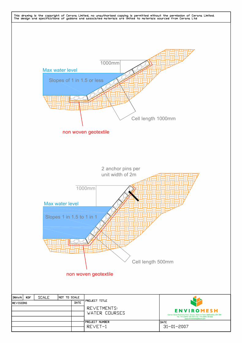
Sloping RevetmentsWater Courses: (See Drawing REVET 1)
A gabion mattress is laid to the slope and should normally extend 1.0m above the maximum anticipated flood level in the water course.For standard gabion mattresses, the maximum slope of the revetment should not exceed 1 in 1.5. The reason for this is to prevent stone migration down the mattress within the cell compartments (the 2.0m dimension of the unit runs along the slope and the 1m cell width runs down the slope). Where the slope of the required revetment is between a grade of 1 in 1.5 and 1 in 1, then it is recommended to position additional diaphragms within the mattress to reduce the cell width to 0.5m down the slope. This limits the potential for stone migration down steeper slopes. Due to the steep angle, it is recommended that 2 number anchor pins per 2.0m run of revetment be installed to prevent the possibility of the entire mattress sliding.It is not recommended to construct a sloping revetment with slopes that are steeper than 1 in 1. Reveting a steep slope in this way should only be considered where the bank is stable otherwise a stepped revetment or a retaining structure should be designed.As with all structures in water courses or for use in coastal protection schemes, mattress toe protection or a gabion toe is required to prevent under scour (See Drawing REVET 4 and REVET 6).
.Coastal Protection: (See Drawing REVET 2)
All gabions used in coastal protection works must be PVC coated and their use is limited to the following situations:
Top of the beach defence and not subjected to constant wave action As a secondary defenceIn sheltered estuary locations
Gabions must not be considered as a main defence when subjected to continual wave action. A gabion mattress is laid to the slope and should normally extend 2.0m above the maximum tide level to allow for run up. Where it is not possible to extend the mattress to the required length due to the height of the bank, the revetment should extend over the crest of a sufficient width and with an embedded gabion below to prevent erosion at the crest through overtopping. For standard gabion mattresses, the maximum slope of the revetment should not exceed 1 in 2.5 for a mattress depth of 0.3m and 1 in 2 for 0.5m deep gabion units used as a revetment.Non woven geotextiles (not spun bonded) should be used underneath all revetments.As with all structures used in water courses or as coastal protection schemes, a mattress toe protection or gabion toe is required to prevent under scour (See Draw-ing REVET 4 and REVET 6).
10
1000mm
Slopes of 1 in 1.5 or less
Slopes 1 in 1.5 to 1 in 1
Max water level
1000mm
non woven geotextile
non woven geotextile
Cell length 500mm
Cell length 1000mm
2 anchor pins per unit width of 2m
Max water level
Garner Street Business Park, Etruria, Stoke-on-Trent, Staffordshire, ST4 7BH Tel: +44 (0)845 136 0101 Fax: +44 (0)845 136 0202
www.enviromeshgabions.com

For slopes of 1 in 2.5 or less mattress depth 300mm
For slopes greater than 1 in 2.5 AND equal to or less than1 in 1gabion units 500mm deep
1500
mm
free
boar
d1000mm
Mean High Water
non woven geotextile
300
Mean High Water
non woven geotextile
Gabion 1m X 0.5m embedded at the crest to prevent scour when embankment isovertopped.
Revetment with adequate free board
Revetment where freeboard is insufficient
For slopes of 1 in 2.5 or less mattress depth300mm
For slopes greater than 1 in 2.5 AND equal to orless than 1 in 1gabion units 500mm deep
Garner Street Business Park, Etruria, Stoke-on-Trent, Staffordshire, ST4 7BH Tel: +44 (0)845 136 0101 Fax: +44 (0)845 136 0202
www.enviromeshgabions.com

Stepped Revetments & Scour ProtectionStepped Revetments: (See Drawing REVET 3)
The following applies to both water courses and coastal protection.
Stepped revetments are used to protect embankments against erosion where they are steeper than 45 degrees. The embankment must be stable in its own right. Stepped revetments are not an alternative to gabion retaining walls where stability is required.
In constructing stepped revetments, the construction must follow the cut line and slope. If areas require filling greater than 0.5m wide behind the stepped revetment, the solution should be a retaining structure and not a stepped revetment.
The stepped revetment is created by offsetting each course from the course below,normally 0.5m to the full height of the unit. Each course should have a unit width of at least 1.5 times the unit depth so that the overhang at the rear is not greater than the unit depth. Thereby the unit above bears down onto the unit below by at least twice the unit depth.
For example, a stepped revetment formed using 0.5m deep units stepped back at 0.5m requires unit widths of 1.5m minimum.
A geotextile separator should be placed behind and below the structure to prevent leaching of fine soil particles.
As with all structures used in water courses or as coastal protection schemes, a mattress toe protection or gabion toe is required to prevent under scour (See Drawing REVET 4 and REVET 6).
13

Slopes 45 to 60 degrees
1000mm
non woven geotextile
Max water level
STEPPED REVETMENTS
REVET 3
Garner Street Business Park, Etruria, Stoke-on-Trent, Staffordshire, ST4 7BH Tel: +44 (0)845 136 0101 Fax: +44 (0)845 136 0202
www.enviromeshgabions.com
15
Stepped Revetments & Scour ProtectionScour Protection:
For retaining structures in water environments, unless the bed material is non erodable, then scour will occur. Although this cannot be readily prevented, the structure must be adequately protected against under scour.
There are two main principle methods of dealing with under scour:
Mattress Toe Protection: (See Drawing REVET 4 and REVET 6)
At the toe of the embankment revetment, a mattress should be provided on the bed to move the effects of the scour away from the toe. The length of toe mattress provided for most soils is 1 to 1.5 times the anticipated scour depth. Where soils are extremely erodable or it is a very fast flowing river, then further advice should be sought from Enviromesh.
If the toe protection is to a coastal scheme, then the length of protection is normally increased to 2 to 3 times the expected scour or beach level variation movement.
Gabion Toe Protection: (See Drawing REVET 5 and REVET 6)
Gabion toe protection entails embedding a gabion to a sufficient depth, greater than the anticipated scour depth or beach level variation.
A geotextile separator should be placed behind and below the scour protection to prevent leaching of fine soil particles.

non woven geotextile
non woven geotextile
Mattress protection as installed
Mattress protection after scour occurs
scour depth
1.5 to 2 times the scourdepth
MATTRESS TOE PROTECTION
REVET 4
Garner Street Business Park, Etruria, Stoke-on-Trent, Staffordshire, ST4 7BH Tel: +44 (0)845 136 0101 Fax: +44 (0)845 136 0202
www.enviromeshgabions.com

non woven geotextile
Gabion scour protection as installed
Gabion toe protection after scour occurs
non woven geotextile
depth of embedded gabion must be greater than theanticipated scour depth
1.5 x scourdepth
scour depth
Gabion toe scour protectionGarner Street Business Park, Etruria, Stoke-on-Trent, Staffordshire, ST4 7BH
Tel: +44 (0)845 136 0101 Fax: +44 (0)845 136 0202www.enviromeshgabions.com
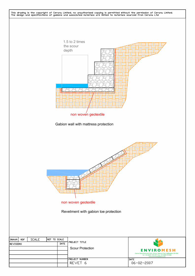
non woven geotextile
Gabion wall with mattress protection
non woven geotextile
Revetment with gabion toe protection
1.5 to 2 times the scourdepth
Scour ProtectionGarner Street Business Park, Etruria, Stoke-on-Trent, Staffordshire, ST4 7BH
Tel: +44 (0)845 136 0101 Fax: +44 (0)845 136 0202www.enviromeshgabions.com

19
Outfalls
The following information applies to free flow outfall pipes and culverts, discharging at or near bed level.
For pumped discharge outfalls or outfalls discharging at a height above the bed, advice should be sought from Enviromesh.
Discharge from pipes into water courses, results in localised formation of eddie currents and turbulent conditions.
These conditions result in a powerful erodable force, therefore protection locally at the discharge point is required.
The protection required is generally a mattress laid to the bed as an apron and should extend sufficient distance upstream and downstream in the water course and also extend out into the stream. The mattress must be laid on a geotextile separator (See Drawing RIVER STRUCTURES 1).
The limits of the protection depend on the discharge velocities from the pipe, the discharge angle of the pipe and the flow conditions in the water course. As a guide the protection should not be less than given in the following table:
Outfall discharge protection recommendations
DISCHARGE MATTRESS BED PROTECTION PROTECTION PROTECTION PIPE PROTECTION UPSTREAM OF DOWNSTREAM OF LENGTH INTO
DIAMETER DEPTH DISCHARGE POINT DISCHARGE POINT WATER COURSE
(m) (m) (m) (m) (m)
0.15 TO 0.3 0.3 1 1 1
0.3 TO 0.5 0.5 1.5 1.5 1.5
0.5 TO 1 0.5 1.5 1.5 2

wingwalls
headwall
apron protection
counter weir
stilling pool
Headwall with counter weir
Section through headwall with counter weir
apron protection
counter weir
headwall
stilling pool
wingwalls
geotextile
RIVER STRUCTURESOUTFALL WITH COUNTER WEIR
RIVER STRUCTURES 1
Garner Street Business Park, Etruria, Stoke-on-Trent, Staffordshire, ST4 7BH Tel: +44 (0)845 136 0101 Fax: +44 (0)845 136 0202
www.enviromeshgabions.com

21
Channel Linings and Drop StructuresWhere water courses are diverted and the soils are erodable, it is necessary to fully line the channel. The method of determining the required depth of mattress protection is as outlined on Page 9 of this guide.
A geotextile separator should be placed beneath the mattress to prevent leaching of the bed and bank soil particles.
The formed channel may be trapezoidal, rectangular or a combination of both, dependant on whether there are land take problems (See Drawing CHANNEL 1).
Where the channel has sloping sides, reference should be made to the criteria on maximum slopes for revetments. If the channel is to have vertical or near vertical sides, then the gabion section forming the channel side should be designed as a retaining structure.
Occasions may arise where the gradient of the water course is steep, giving rise to high velocities in the channel. It may be necessary to reduce the hydraulic gradient through introducing drop structures or weirs. The effect of these is to reduce the energy at each drop and to slacken the gradient. On extremely steep slopes, a series of drops in very close proximity are constructed. This type of structure is known as a cascade(See Drawings RIVER STRUCTURES 2 and 3).
For drop structures or weirs with a large change in level, then a counter weir with a stilling basin may be required to dissipate the energy.
If the water course is in a location where a high bed load is transported, then the crest of the weir or the steps of the cascade may require protection with concrete to prevent abrasion of the mesh.
Weirs are normally rectangular or trapezoidal in section with the structure keyed into the bank to prevent the structure being outflanked. The depth of scour protection depth required immediately down stream should be a minimum of 0.5m thick.

Diaphragms on the bank to run parallelto the bank.
Diaphragms on the bed to be across the flow
Mattress protection to a trapezoidal channel.
Gabion and mattress protection to rectangular channel
Diaphragms on the bed to be across the flow
CHANNEL LININGS
CHANNEL-1
Garner Street Business Park, Etruria, Stoke-on-Trent, Staffordshire, ST4 7BH Tel: +44 (0)845 136 0101 Fax: +44 (0)845 136 0202
www.enviromeshgabions.com

Section through weir
apron protection
counter weir
WEIR
stilling pool
wingwalls
GEOTEXTILE
Reducing the hydraulic gradient with steps
GEOTEXTILE
Gabion matress units
WEIRS AND DROP STRUCTURES
RIVER STRUCTURES 2
Garner Street Business Park, Etruria, Stoke-on-Trent, Staffordshire, ST4 7BH Tel: +44 (0)845 136 0101 Fax: +44 (0)845 136 0202
www.enviromeshgabions.com

geotextile
Mattress bed protection
Mattress bed protection
Stepped gabion units inclined at 6 degrees to horizontal to form cascade.
Side wall not shown for clarity
RIVER STRUCTURES 3
Garner Street Business Park, Etruria, Stoke-on-Trent, Staffordshire, ST4 7BH Tel: +44 (0)845 136 0101 Fax: +44 (0)845 136 0202
www.enviromeshgabions.com

25
Groynes:River Groynes:
Groynes are structures that extend from the river bank out into the water course. Their purpose is to divert the flow away from the river bank to prevent its erosion. A series of groynes along a bank will encourage deposition of bed material between the groynes, raising the bed level adjacent to the river bank.
At the head of the groyne, the bed scours which results in deepening of the river beyond the limit of the groyne.
Stub or short groynes are often constructed to improve fish habitat in a river as deep pools are formed at the head of the groyne.
The spacing of the groynes to achieve the desired result is dependant on the river regime.
Where the bed is very stable, the effect of deepening the main channel may be limited.
A scour protection apron is required around the groyne so that the scour does not undermine the groyne itself (See Drawing RIVER STRUCTURES 4).
Sea Groynes:
The purpose of sea groynes is to prevent erosion of the foreshore by causing deposition of beach material between the groynes. The groynes, as with river groynes, require an apron protection to prevent scour undermining the groyne itself.
Normally gabions are not recommended in a regular wave zone, but in the case of sea groynes this will occur. The type of gabion to be used for sea gabions must always be the PVC coated flexible woven mesh type. This is because the groyne may be distorted and requires the flexible mesh for the unit to maintain its integrity. It is very important that the units are well packed and constructed otherwise the gabion infill could abrade the protective PVC coating.
In the long term as the beach replenishment is established, it may require the groyne to be increased in height. This can be achieved by adding another course of gabions. A classic example of a very successful sea groyning scheme is at Hunstanton in Norfolk.
The use of sea groynes should be limited to sandy beaches. Shingle or rocky beaches will result in abrasion of the mesh coatings..

GROYNES
RIVER STRUCTURES 4 07-02-2007
Garner Street Business Park, Etruria, Stoke-on-Trent, Staffordshire, ST4 7BH Tel: +44 (0)845 136 0101 Fax: +44 (0)845 136 0202
www.enviromeshgabions.com
Groyne example
The head of the groyne has a greater area of mattress scour protection than the leg of the groyne.

Garner Street Business Park, Etruria, Stoke-on-Trent, Staffordshire, ST4 7BHTel: +44 (0)845 136 0101 Fax: +44 (0)845 136 0202
www.enviromeshgaions.com
WOVEN HEXAGONAL MESH MATTRESS SPECIFICATION
2.0/3.0mm Wire Diameter Galvanised and PVC CoatedMattresses shall comply with the following specifications
MANUFACTURE: Mattresses shall be manufactured from double twist hexagonal woven wire mesh in accordance with EN 10223-3:1998.
Diaphragms to be at nominal 1m centres on the unit length.
MESH SIZE: The mesh openings shall be hexagonal and of a nominal dimension of 60mm x 80mm.
MESH WIRE: The nominal wire mesh diameter for the body of the mattress shall be 2.0mm in diameter and of a nominal 2.70mm for the edge selvedge wire.All wire shall be in accordance with BS EN 10218-2:1997.The tensile strength falls within a range of 350 to 575 N/mm2
CORROSION Wire shall be zinc coated to BS EN10244-2 2001.PROTECTION: An additional extruded u-PVC coating of nominal 0.5mm radial thickness is
applied over the galvanised wire.
JOINTING: Mattresses shall be provided with lacing wire or stainless steel “C” rings for site assembly. The lacing wire shall be of a nominal wire diameter of 2.2mm (all in accordance with the corrosion protection specified) for final jointing.
ROCKFILL: Mattress fill shall be a hard, durable and non frost susceptible (rock or stone type) having a minimum dimension not less than the mesh opening and a maximum dimension of 200mm.
CONSTRUCTION: All rock fill shall be packed tightly to minimize voids and the rockfill on the exposed face of the gabion is to be hand packed.
Adjacent units are to be jointed with a continuous lacing or pneumatically closed with “C” rings one every other mesh opening on all joints.
Units shall be filled such that the mesh lid bears down onto the rock fill. The lid shall be wired down or “C” ringed as above on all joints and across the diaphragms.
SPEC 13: 09-02-2007
27
Registered Office: Unit 5, The Cobden Centre, Folly Brook Road, Emerald Park, Emersons Green, Bristol BS16 7FQEnviromesh is a trading name of Cerana Limited. Registered in England No. 5065615

Garner Street Business Park, Etruria, Stoke-on-Trent, Staffordshire, ST4 7BHTel: +44 (0)845 136 0101 Fax: +44 (0)845 136 0202
www.enviromeshgabions.com
WELDED MESH GABION SPECIFICATIONGabion 27 System – Galfan Coated
Gabions shall comply with the following specifications
MANUFACTURE: Gabions shall be manufactured from a hard drawn steel wire formed into a bi-axial mesh grid by electrically welding the cross wires at every intersection. The weld strength is to be 70% of the ultimate tensile strength of the wire. Gabions are to be factory assembled with stainless steel clips (minimum one every third mesh opening) connecting side panels and diaphragms to the base panel and the lid to the face panel. Diaphragms are to be at 686mm centres within the unit and a maximum of 1.38m across the width.
MESH SIZE: The mesh openings shall be square and of a nominal dimension of 76.2mm on the grid.
MESH WIRE: The nominal wire diameter shall be 3.0mm for the base, ends, diaphragm and the lid on the upper most unit and a 4.0mm diameter wire for the front and rear panels. All wire is in accordance with BS EN 10218-3: 1997 and of a tensile strength within the range of 540-770 N/mm2.
CORROSION Wire shall be galfan coated (95% Zn / 5% Al) in accordance with PROTECTION: BS EN 10244-2:2001.
JOINTING: Gabions shall be provided with lacing wire and helical spirals for site assembly. The lacing wire shall be of a nominal wire diameter of 2.2mm and the helicals of 3.00mm (all in accordance with the corrosion protection specified) for final jointing.
ROCKFILL: Gabion fill shall be a hard durable and non frost susceptible (rock or stone type) having a minimum dimension of not less than the mesh opening and a maximum dimension of 200mm.
CONSTRUCTION: All rock fill shall be packed tightly to minimize voids and the rock fill on the exposed face of the gabion is to be hand packed. Corner bracing ties 2 per face and rear cell at mid height on 686mm high units and at 4 per face and rear cell at third heights on 1m high units. Adjacent units are to be jointed with helical spirals on the vertical joints and laced on the horizontal joints at the front and rear of coursed joints.Units shall be filled such that the mesh base of the unit above bears onto the rock fill. The lid shall be wired down on all joints and across the diaphragms.
Above jointing is supplied as standard, the following alternatives are also acceptable:
Pneumatically closed galfan coated “C” rings for horizontal jointing at 1 ring every other mesh.
SPEC 1: 29-01-2007
28
Registered Office: Unit 5, The Cobden Centre, Folly Brook Road, Emerald Park, Emersons Green, Bristol BS16 7FQEnviromesh is a trading name of Cerana Limited. Registered in England No. 5065615

Garner Street Business Park, Etruria, Stoke-on-Trent, Staffordshire, ST4 7BHTel: +44 (0)845 136 0101 Fax: +44 (0)845 136 0202
www.enviromeshgabions.com
WELDED MESH GABION SPECIFICATION Gabion 39 System - 3.00mm Wire Diameter - Galfan Coated
Gabions shall comply with the following specifications
MANUFACTURE: Gabions shall be manufactured from a hard drawn steel wire formed into a bi-axial mesh grid by electrically welding the cross wires at every intersection. The weld strength is to be 70% of the ultimate tensile strength of the wire. Gabions are to be factory assembled with stainless steel clips (minimum one every third mesh opening) connecting side panels and diaphragms to the base panel and the lid to the face panel.Diaphragms to be at nominal 1m centres on the unit length, except for 1.5m long gabions which have no internal diaphragm.
MESH SIZE: The mesh openings shall be square and of a nominal dimension of 76.2mm on the grid.
MESH WIRE: The nominal wire diameter shall be 3.0mm in accordance with BS EN 10218-2 1997. The tensile strength falls within a range of 540-770 N/mm2.
CORROSION Wire shall be galfan coated (95% Zn / 5% Al) in accordance with BS EN 10244-2:PROTECTION: 2001.
JOINTING: Gabions shall be provided with lacing wire for site assembly. The lacing wire shall be of a nominal wire diameter of 2.2mm (all in accordance with the corrosion protection specified) for final jointing.
ROCKFILL: Gabion fill shall be a hard durable and non frost susceptible (rock or stone type) having a minimum dimension not less than the mesh opening and a maximum dimension of 200mm.
CONSTRUCTION: All rock fill shall be packed tightly to minimize voids and the rock fill on the exposed face of the gabion is to be hand packed. Internal windlass bracing ties are to be incorporated at 2 per 1sqm of face at 1/3rd & 2/3 intervals for 1m high units and 1 placed centrally for 0.5m high units. The adjacent gabion units are to be tied together with continuous lacing on the vertical joints as well as horizontally at the front and rear of coursed joints. The units shall be filled such that the mesh lid bears down onto the rock fill. The lid shall be wired down on all joints and across the diaphragms.
Above jointing and internal bracing is supplied as standard. The following alternatives are also acceptable:
Full height helicals in 3.0mm galfan coated wire for vertical jointingPneumatically closed galfan coated “C” rings for vertical and horizontal jointing at 1 ring every other mesh opening.Galfan coated preformed corner bracing ties 4 per m2 of face.
SPEC 2: 29-01-2007
29
Registered Office: Unit 5, The Cobden Centre, Folly Brook Road, Emerald Park, Emersons Green, Bristol BS16 7FQEnviromesh is a trading name of Cerana Limited. Registered in England No. 5065615

Garner Street Business Park, Etruria, Stoke-on-Trent, Staffordshire, ST4 7BHTel: +44 (0)845 136 0101 Fax: +44 (0)845 136 0202
www.enviromeshgabions.com
WELDED MESH GABION SPECIFICATION Gabion 39 System - 4.00mm Wire Diameter - Galfan Coated
Gabions shall comply with the following specifications
MANUFACTURE: Gabions shall be manufactured from a hard drawn steel wire formed into a bi-axial mesh grid by electrically welding the cross wires at every intersection. The weld strength is to be 70% of the ultimate tensile strength of the wire. Gabions are to be factory assembled with stainless steel clips (minimum one every third mesh opening) connecting side panels and diaphragms to the base panel and the lid to the face panel.Diaphragms to be at nominal 1m centres on the unit length, except for 1.5m long gabions which have no internal diaphragm.
MESH SIZE: The mesh openings shall be square and of a nominal dimension of 76.2mm on the grid.
MESH WIRE: The nominal wire diameter shall be 4.0mm in accordance with BS EN 10218-2 1997. The tensile strength falls within a range of 540-770 N/mm2.
CORROSION Wire shall be galfan coated (95% Zn / 5% Al) in accordance with BS EN 10244-2:PROTECTION: 2001.
JOINTING: Gabions shall be provided with lacing wire for site assembly. The lacing wire shall be of a nominal wire diameter of 2.2mm (all in accordance with the corrosion protection specified) for final jointing.
ROCKFILL: Gabion fill shall be a hard durable and non frost susceptible (rock or stone type) having a minimum dimension not less than the mesh opening and a maximum dimension of 200mm.
CONSTRUCTION: All rock fill shall be packed tightly to minimize voids and the rock fill on the exposed face of the gabion is to be hand packed. Internal windlass bracing ties are to be incorporated at 2 per 1sqm of face at 1/3rd & 2/3 intervals for 1m high units and 1 placed centrally for 0.5m high units. The adjacent gabion units are to be tied together with continuous lacing on the vertical joints as well as horizontally at the front and rear of coursed joints. The units shall be filled such that the mesh lid bears down onto the rock fill. The lid shall be wired down on all joints and across the diaphragms.
Above jointing and internal bracing is supplied as standard. The following alternatives are also acceptable:
Full height helicals in 3.0mm galfan coated wire for vertical jointingPneumatically closed galfan coated “C” rings for vertical and horizontal jointing at 1 ring every other mesh opening.Galfan coated preformed corner bracing ties 4 per m2 of face.
SPEC 3: 29-01-2007
30
Registered Office: Unit 5, The Cobden Centre, Folly Brook Road, Emerald Park, Emersons Green, Bristol BS16 7FQEnviromesh is a trading name of Cerana Limited. Registered in England No. 5065615

Garner Street Business Park, Etruria, Stoke-on-Trent, Staffordshire, ST4 7BHTel: +44 (0)845 136 0101 Fax: +44 (0)845 136 0202
www.enviromeshgabions.com
WELDED MESH GABION SPECIFICATION Gabion 39 System - 3.00/4.00mm Wire Diameter - Galfan Coated
Gabions shall comply with the following specifications
MANUFACTURE: Gabions shall be manufactured from a hard drawn steel wire formed into a bi-axial mesh grid by electrically welding the cross wires at every intersection. The weld strength is to be 70% of the ultimate tensile strength of the wire. Gabions are to be factory assembled with stainless steel clips (minimum one every third mesh opening) connecting side panels and diaphragms to the base panel and the lid to the face panel.Diaphragms to be at nominal 1m centres on the unit length, except for 1.5m long gabions which have no internal diaphragm.
MESH SIZE: The mesh openings shall be square and of a nominal dimension of 76.2mm on the grid.
MESH WIRE: The nominal wire diameter shall be 3.0mm for the lid, base, back and internal panels and from a 4.00mm wire diameter for the face panel, all in accordance with BS EN 10218-2 1997. The tensile strength falls within a range of 540-770 N/mm2.
CORROSION Wire shall be galfan coated (95% Zn / 5% Al) in accordance with BS EN 10244-2:PROTECTION: 2001.
JOINTING: Gabions shall be provided with lacing wire for site assembly. The lacing wire shall be of a nominal wire diameter of 2.2mm (all in accordance with the corrosion protection specified) for final jointing.
ROCKFILL: Gabion fill shall be a hard durable and non frost susceptible (rock or stone type) having a minimum dimension not less than the mesh opening and a maximum dimension of 200mm.
CONSTRUCTION: All rock fill shall be packed tightly to minimize voids and the rock fill on the exposed face of the gabion is to be hand packed. Internal windlass bracing ties are to be incorporated at 2 per 1sqm of face at 1/3rd & 2/3 intervals for 1m high units and 1 placed centrally for 0.5m high units. The adjacent gabion units are to be tied together with continuous lacing on the vertical joints as well as horizontally at the front and rear of coursed joints. The units shall be filled such that the mesh lid bears down onto the rock fill. The lid shall be wired down on all joints and across the diaphragms.
Above jointing and internal bracing is supplied as standard. The following alternatives are also acceptable:
Full height helicals in 3.0mm galfan coated wire for vertical jointingPneumatically closed galfan coated “C” rings for vertical and horizontal jointing at 1 ring every other mesh opening.Galfan coated preformed corner bracing ties 4 per m2 of face.
SPEC 4: 29-01-2007
31
Registered Office: Unit 5, The Cobden Centre, Folly Brook Road, Emerald Park, Emersons Green, Bristol BS16 7FQEnviromesh is a trading name of Cerana Limited. Registered in England No. 5065615

Garner Street Business Park, Etruria, Stoke-on-Trent, Staffordshire, ST4 7BHTel: +44 (0)845 136 0101 Fax: +44 (0)845 136 0202
www.enviromeshgabions.com
WELDED MESH GABION SPECIFICATION Gabion 39 System - 5.00mm Wire Diameter - Galfan Coated
Gabions shall comply with the following specifications
MANUFACTURE: Gabions shall be manufactured from a hard drawn steel wire formed into a bi-axial mesh grid by electrically welding the cross wires at every intersection. The weld strength is to be 70% of the ultimate tensile strength of the wire. Gabions are to be factory assembled with stainless steel clips (minimum one every third mesh opening) connecting side panels and diaphragms to the base panel and the lid to the face panel.Diaphragms to be at nominal 1m centres on the unit length, except for 1.5m long gabions which have no internal diaphragm.
MESH SIZE: The mesh openings shall be square and of a nominal dimension of 76.2mm on the grid.
MESH WIRE: The nominal wire diameter shall be 5.0mm in accordance with BS EN 10218-2 1997. The tensile strength falls within a range of 540-770 N/mm2.
CORROSION Wire shall be galfan coated (95% Zn / 5% Al) in accordance with BS EN 10244-2:PROTECTION: 2001.
JOINTING: Gabions shall be provided with lacing wire for site assembly. The lacing wire shall be of a nominal wire diameter of 2.2mm (all in accordance with the corrosion protection specified) for final jointing.
ROCKFILL: Gabion fill shall be a hard durable and non frost susceptible (rock or stone type) having a minimum dimension not less than the mesh opening and a maximum dimension of 200mm.
CONSTRUCTION: All rock fill shall be packed tightly to minimize voids and the rock fill on the exposed face of the gabion is to be hand packed. Internal windlass bracing ties are to be incorporated at 2 per 1sqm of face at 1/3rd & 2/3 intervals for 1m high units and 1 placed centrally for 0.5m high units. The adjacent gabion units are to be tied together with continuous lacing on the vertical joints as well as horizontally at the front and rear of coursed joints. The units shall be filled such that the mesh lid bears down onto the rock fill. The lid shall be wired down on all joints and across the diaphragms.
Above jointing and internal bracing is supplied as standard. The following alternatives are also acceptable:
Full height helicals in 3.0mm galfan coated wire for vertical jointingPneumatically closed galfan coated “C” rings for vertical and horizontal jointing at 1 ring every other mesh opening.Galfan coated preformed corner bracing ties 4 per m2 of face.
SPEC 5: 29-01-2007
32
Registered Office: Unit 5, The Cobden Centre, Folly Brook Road, Emerald Park, Emersons Green, Bristol BS16 7FQEnviromesh is a trading name of Cerana Limited. Registered in England No. 5065615

Garner Street Business Park, Etruria, Stoke-on-Trent, Staffordshire, ST4 7BHTel: +44 (0)845 136 0101 Fax: +44 (0)845 136 0202
www.enviromeshgabions.com
WOVEN HEXAGONAL MESH GABION SPECIFICATION
2.70mm Wire Diameter Galvanised CoatedGabions shall comply with the following specifications
MANUFACTURE: Gabions shall be manufactured from double twist hexagonal woven wire mesh in accordance with BS EN 10223-3:1998.
Diaphragms to be at nominal 1m centres on the unit length, except for 1.5m long gabions which have no internal diaphragm.
MESH SIZE: The mesh openings shall be hexagonal and of a nominal dimension of 80mm x 100mm.
MESH WIRE: The nominal wire mesh diameter for the body of the gabion shall be 2.70mm in diameter and of a nominal 3.40mm for the edge selvedge wire.All wire shall be in accordance with BS EN 10218-2:1997.The tensile strength falls within a range of 350 to 575 N/mm2.
CORROSION Wire shall be zinc coated to BS EN10244-2:2001PROTECTION:
JOINTING: Gabions shall be provided with lacing wire or ‘C’ for site assembly. The lacing wire shall be of a nominal wire diameter of 2.2mm (all in accordance with the corrosion specified) for final jointing.
ROCKFILL: Gabion fill shall be a hard durable and non frost susceptible (rock or stone type) having a minimum dimension not less than the mesh opening and a maximum dimension of 200mm.
CONSTRUCTION: All rock fill shall be packed tightly to minimize voids and the rock fill on the exposed face of the gabion is to be hand packed. Internal windlass bracing ties are to be incorporated at 2 per 1sqm of face at 1/3rd & 2/3 intervals for 1m high units and 1 placed centrally for 0.5m high units. The adjacent gabion units are to be tied together with continuous lacing on the vertical joints as well as horizontally at the front and rear of coursed joints. Alternatively ‘C’ rings may be used with a pneumatic tool with one being placed every other mesh space.The units shall be filled such that the mesh lid bears onto the rock fill. The lid shallbe wired down or “C” ringed as above on all joints and across the diaphragms.
SPEC 6: 29-01-2007
33
Registered Office: Unit 5, The Cobden Centre, Folly Brook Road, Emerald Park, Emersons Green, Bristol BS16 7FQEnviromesh is a trading name of Cerana Limited. Registered in England No. 5065615

Garner Street Business Park, Etruria, Stoke-on-Trent, Staffordshire, ST4 7BHTel: +44 (0)845 136 0101 Fax: +44 (0)845 136 0202
www.enviromeshgabions.com
WOVEN HEXAGONAL MESH GABION SPECIFICATION
2.70 / 3.70mm Wire Diameter Galvanised and PVC CoatedGabions shall comply with the following specifications
MANUFACTURE: Gabions shall be manufactured from double twist hexagonal woven wire mesh in accordance with BS EN 10223-3:1998.
Diaphragms to be at nominal 1m centres on the unit length, except for 1.5m long gabions which have no internal diaphragm.
MESH SIZE: The mesh openings shall be hexagonal and of a nominal dimension of 80mm x 100mm.
MESH WIRE: The nominal wire mesh diameter for the body of the gabion shall be 2.70mm in diameter and of a nominal 3.40mm for the edge selvedge wire.All wire shall be in accordance with BS EN 10218-2:1997.The tensile strength falls within a range of 350 to 575 N/mm2.
CORROSION Wire shall be zinc coated to BS EN10244-2:2001.PROTECTION: An additional extruded u-PVC coating of nominal 0.5mm radial thickness is
applied over the galvanised wire.
JOINTING: Gabions shall be provided with lacing wire or ‘C’ for site assembly. The lacing wire shall be of a nominal wire diameter of 2.2mm (all in accordance with the corrosion specified) for final jointing.
ROCKFILL: Gabion fill shall be a hard durable and non frost susceptible (rock or stone type) having a minimum dimension not less than the mesh opening and a maximum dimension of 200mm.
CONSTRUCTION: All rock fill shall be packed tightly to minimize voids and the rock fill on the exposed face of the gabion is to be hand packed. Internal windlass bracing ties are to be incorporated at 2 per 1sqm of face at 1/3rd & 2/3 intervals for 1m high units and 1 placed centrally for 0.5m high units. The adjacent gabion units are to be tied together with continuous lacing on the vertical joints as well as horizontally at the front and rear of coursed joints. Alternatively ‘C’ rings may be used with a pneumatic tool with one being placed every other mesh space.The units shall be filled such that the mesh lid bears onto the rock fill. The lid shall be wired down or “C” ringed as above on all joints and across the diaphragms.
SPEC 7: 29-01-2007
34
Registered Office: Unit 5, The Cobden Centre, Folly Brook Road, Emerald Park, Emersons Green, Bristol BS16 7FQEnviromesh is a trading name of Cerana Limited. Registered in England No. 5065615

CONTACTS:
Roger Farmer Mob: +44 (0) 7725 244 636Technical Director Email: [email protected]
Neil Holmes Mob: +44 (0) 7725 244 637Commercial Director Email: [email protected]
20/02/07 Edition 1
Garner Street Business Park, Etruria, Stoke-on-Trent,Staffordshire, ST4 7BH
Tel: +44 (0) 845 136 0101 Fax: +44 (0) 845 136 0202
www.enviromeshgabions.com
Registered Office: Unit 5, The Cobden Centre, Folly Brook Road, Emerald Park, Emersons Green, Bristol BS16 7FQEnviromesh is a trading name of Cerana Limited. Registered in England No. 5065615