development and statistical characterization of slug in
TRANSCRIPT

Mechanics & Industry 16, 307 (2015)c© AFM, EDP Sciences 2015DOI: 10.1051/meca/2015007www.mechanics-industry.org
Mechanics&Industry
Development and statistical characterization of slugin two-phase flow along horizontal pipeline
I. Belgacem1,a, Y. Salhi1, M. Hammoudi1, E.K. Si-Ahmed1,2 and J. Legrand2
1 Laboratoire de Mecanique des Fluides Theorique et Appliquee, Faculte de physique, U.S.T.H.B, Alger, Algerie2 GEPEA, Universite de Nantes, CNRS, UMR 6144, CRTT-BP406, 44602 Saint-Nazaire, France
Received 6 April 2014, Accepted 9 December 2014
Abstract – In many industrial processes, the presence of liquid and gas mixtures creates a slug flow. Thiskind of regime is observed when slug’s liquid blocks the whole pipeline and moves as a coherent massdownstream at a velocity approximately equal to the gas velocity. The aim of this study is to providestatistical information on slug in two-phase flow in horizontal pipe. Experiments were conducted in a pipeof 0.04 m diameter and a length of 14 m. First of all, a flow regime map is compiled for air/water twophase flows. Data on pressure gradient, slug frequency and liquid holdup are presented. It was found thatmean slug frequency clearly increases as the superficial liquid velocity increases but it weakly depends onthe superficial gas velocity.
Key words: Slug / stratified transition / pressure gradient / liquid holdup / frequency / transitionalvelocity
Nomenclature
J Superficial velocity of phase j (m.s−1)
d Pipe diameter (m)
t Time (s)
f Slug frequency (1/s)
x Distance from the inlet (m)
X Liquid volume fraction
V Velocity of elongated bubble
H/D Liquid holdup
St Strouhal number
Sub and super scripts
max Maximum value
l For liquid
g For gas
t Translational
m Mixture
1 Introduction
Two-phase gas/liquid flows occur in numerous piecesof engineering equipment’s such as boiler, condensers,
a Corresponding author:[email protected]
reactor, heat exchanger and oil/gas pipelines. In gas-liquid flow the two phases can be distributed in differ-ent configurations, recognized as flow patterns. Each flowpattern in a system depends on the operational variables(gas and liquid flow rates), geometry (pipe diameter andinclination angle), and physical properties of the fluids.In horizontal and near horizontal pipelines, flow patternsare usually classified into the following categories, strat-ified (smooth and wavy), intermittent (plug and slug),annular, and dispersed bubble.
Of all flow patterns encountered in field operations,slug flow is the dominant one in horizontal and near hor-izontal pipelines, and is also the most complicated one.Classical flow maps (e.g. [1–3]), show that the intermit-tent regime exists for a wide range of gas and liquid flowrates in a horizontal two-phase flow configuration. It ischaracterized by an alternate flow of liquid slugs andgas pockets, resulting in an inherently unsteady hydrody-namic behavior. All the important design variables, suchas gas and liquid velocity profiles, liquid holdup distri-bution, and pressure drop vary axially and radially andexhibit fluctuations, even when the inlet liquid and gasflow rates are constant. This makes prediction of slugflow characteristics difficult and challenging. Therefore,such flow is considered as an extremely complicated flowpattern. The complexity evolves from the intermittencyof the flow and the large velocity gaps between the variousslug regions, also the phases usually have very different
Article published by EDP Sciences

I. Belgacem et al.: Mechanics & Industry 16, 307 (2015)
Fig. 1. Schematic representation of basic slug unit.
properties and can be arranged in a variety of geometri-cal pattern in the duct. In Figure 1 the phase’s distribu-tion of gas and liquid encountered in slug flow is depictedschematically.
Several studies have been carried out during the pastfifty years in an attempt to describe slug flow in horizon-tal pipelines. The earliest attempt to model horizontalslug flow was by Kordyban [4]. Slugs were visualized assliding at the gas phase velocity over a liquid film withno interaction between the slugs and the film. The slugunit consists of large gas bubbles flow alternately withliquid slugs at randomly fluctuating frequency [5]. Theliquid slug may be either of pure liquid or aerated as aresult of gas entrainment (in the form of small dispersedbubbles) from the large bubbles [6,7]. Many authors haveaddressed the mechanism of slug formation and estab-lished approximate criteria for the transition from strati-fied to slug flow. Visual observations of wave growth andslug formation show that the slugs are formed from longwaves, when they become large enough to bridge the pipecross-section via a classical Kelvin-Helmholtz instabilityto occupy the entire pipe cross section [3,8–11], or/and byaccumulation of liquid at valleys of irregular terrains [12].Wave coalescence has also been observed as an importantmechanism in the slug formation, especially at high gasflow rates in horizontal pipes [13].
Despite a large amount of research focused on pre-dicting the transition boundaries between two phase flowregimes and in particular the behavior of slugs, there arestill large holes in our understanding. Therefore, this workwas undertaken to provide statistical informations of two-phase flow in horizontal tube especially for slug flow pat-tern. At first, it aims to build a flow regime map. Then,the development of slug and some parameters includingpressure, frequency, and liquid holdup are investigated.
1.1 Experimental facility and measurement techniques
The experiments were conducted in a horizontal pipeof 0.04 m diameter and a 14 m length. The experimen-tal setup used to detect slugs is sketched in Figure 2;our experimental loop is adapted to generate a gas-liquidtwo phase flow concurrently. It operates in closed cir-cuit for the liquid component, open for the gas compo-nent. The liquid flow is provided by a centrifugal No-ryle pump, the nominal operating point gives a volumeflow-rate 10 m3.h−1 for a delivery height of 9 m. Theair is provided from a compressor. Both fluids air/water
Fig. 2. Description of the experimental setup. 1: compressor,2: liquid tank, 3: Frame, 4: liquid-gas separator, 5: centrifu-gal pump, 6: liquid by pass line, 7: Liquid debimeter, 8: Gasdebimeter, 9: liquid-gas mixer, 10: visual section, 11: Testsection.
arrive in a cylindrical mixing chamber which is fed thepipe made of Plexiglas with the resulting two-phase com-ponent. Prior to the experiments, we first set the hori-zontal line; to avoid transition which is due to the effectof the inclination of the pipe [14]. Therefore, it is im-perative to remove all traces of oil in the air using airfilters to maintain good experimental conditions. Visual-ization of the flow regime is achieved at 7m from the inletof the pipe using a Canon HG20 camera (1920 × 1080full HD24 bits/s) with high resolution. Gas flow mea-surement is performed by two Rota meters VMRP010092and VMRP010083 type, our measuring range lies between10 l.mn−1 up to 400 l.mn−1, while the liquid rate rangingfrom 10 l.mn−1 to 68 l.mn−1 is measured by an ultrasonicflow meter type PT878 portable.
2 Results and discussion
2.1 Flow regime map
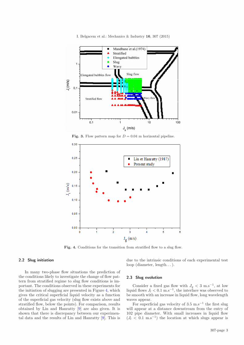
In order to enhance the confidence level of our experi-mental investigation, a flow regime map was compiled. Inindustrial applications the prediction of flow regimes inhorizontal multiphase pipe flow is important for reliabledesign of transportation system. In this work, detectionof flow was carried using two methods visualization andwall pressure fluctuations analysis [15]. For given superfi-cial water velocity (Jl) a range of superficial air velocities(Jg) was swept, the flow regime determination was carriedvisually. Figure 3 exhibits the predicted flow regime type(shown as points) on a flow regime map in comparisonto the Mandhane et al. [2] transition lines for horizontalflow.
Following the flow regime map, a study of the char-acteristics of slug flow in the 0.04 m pipeline was carriedout.
307-page 2
I. Belgacem et al.: Mechanics & Industry 16, 307 (2015)
Fig. 3. Flow pattern map for D = 0.04 m horizontal pipeline.
Fig. 4. Conditions for the transition from stratified flow to a slug flow.
2.2 Slug initiation
In many two-phase flow situations the prediction ofthe conditions likely to investigate the change of flow pat-tern from stratified regime to slug flow conditions is im-portant. The conditions observed in these experiments forthe initiation of slugging are presented in Figure 4, whichgives the critical superficial liquid velocity as a functionof the superficial gas velocity (slug flow exists above andstratified flow, below the points). For comparison, resultsobtained by Lin and Hanratty [9] are also given. It isshown that there is discrepancy between our experimen-tal data and the results of Lin and Hanratty [9]. This is
due to the intrinsic conditions of each experimental testloop (diameter, length. . . ).
2.3 Slug evolution
Consider a fixed gas flow with Jg < 3 m.s−1, at lowliquid flows Jl < 0.1 m.s−1, the interface was observed tobe smooth with an increase in liquid flow, long wavelengthwaves appear.
For superficial gas velocity of 3.5 m.s−1 the first slugwill appear at a distance downstream from the entry of102 pipe diameter. With small increases in liquid flow(Jl < 0.1 m.s−1) the location at which slugs appear is
307-page 3

I. Belgacem et al.: Mechanics & Industry 16, 307 (2015)
Fig. 5. Video images of slug formation.
much closer to the inlet. In addition, more than one slugexists in the pipe at a given time. Figure 5 shows theevolution of slug for Jl = 0.18 m.s−1 and Jg = 4.5 m.s−1.
2.4 Pressure variation
Pressure gradients were measured with a capacitivedifferential pressure transducer. The taps were placed at5.29 m from the entrance of the test section. Measure-ments of the pressure fluctuations according to the super-ficial gas velocity, presented in Figure 6, prove that thereduction in Jg is accompanied by a progressive reductionin the amplitude of the pressure fluctuation. Analysis ofthe signals of pressure shows that the fall of pressure ofthe film zone between two slugs can be neglected com-pared with that produced in the zone of mixture [16].
2.5 Slug frequency
The frequency of slugging defined as the number ofslugs passing a stationary observer per unit time was de-termined by treatment of the electric signal tension deliv-ered by the piezoelectric pressure pick-up using a methodsimilar to that proposed by Lin and Hanratty [9], Fanet al. [17] and Wood and Hanratty [11]. According tothese authors the arrival of a slug in a point is accom-panied by a sudden increase in the level of liquid as well
(a)
(b)
Fig. 6. Evolution of the pressure for various superficial gasvelocities. (a) Jl = 0.18 m.s−1; Jg = 0.79 m.s−1. (b) Jl =0.18 m.s−1; Jg = 1.83 m.s−1.
as pressure. Knowing the linear relation which binds thepressure to the electric tension delivered by the sensor,it follows from there that the peaks of tension observedreveal the passage of the slugs. Consequently, the count-ing of the peaks for one duration of 272 (s) enabled usto measure the frequencies of the slugs. It should be no-ticed that the results obtained by this method were cor-roborated by counting the slugs during the visioning ofthe videos recorded simultaneously with the acquisitionof the signal delivered by the sensor. Figures 7a and 7bshow clearly that slug frequency increases as the superfi-cial liquid velocity increases but it weakly depends on thesuperficial gas velocity.
The measured slug frequency data at x/D = 132.24are calculated with dimensionless parameters and plottedin Figure 7c, in which the Strouhal number St is shown asa function of the liquid volume fraction Xl. It is observedthat the relation can be correlated by the equation of thefollowing form, as reported by Fossa et al. [18].
St =0.05Xl
1 − 1.675Xl + 0.768X2l
(1)
307-page 4

I. Belgacem et al.: Mechanics & Industry 16, 307 (2015)
(a) (b)
(c)
Fig. 7. (a) Frequency of the slugs according to the superficial gas velocity for various superficial liquid velocities. (b) Frequencyof the slugs according to the superficial liquid velocity for various superficial gas velocities. (c) Correlation of slug frequencymeasured. Comparison with the correlation of Fossa et al. [18].
2.6 Holdup of slug
Figure 8 shows measurements of liquid holdup (H/D)at a distance x/D = 132.24 for a superficial liquid velocityJl = 0.14 m.s−1 and three superficial gas velocities.
The H/D measured with the pressure probes does notreach a value of unity when a slug passes because of thepresence of gas bubbles. The average value of (H/D)maxis ∼0.8.
2.7 Translational velocity of elongated bubble
The translational velocity of elongated bubble (Vt) asa function of the local mixture velocity (Vm) is shown inFigure 9. It is observed that the mean value of Vt increaseslinearly with the mixture velocity. The measured trans-lational velocities of elongated bubble are compared withthe predicted values from the model proposed by Nicklinet al. [19] with good agreement.
Vt = C0 Vm + V0 (2)
3 Conclusion
In this work, an experimental study of the slug flowin horizontal pipe is presented. The interest was focusedin the mechanical aspect by measuring the variations ofpressure at time of slug’s passage, and in the physicalaspect by determination of the flow parameters.
The following conclusions may be drawn:
– The reduction in superficial gas velocity is accompa-nied by a progressive reduction in the amplitude ofthe fluctuations in pressure.
– The slug frequency is not variant with the pressure.– The frequency of the slug’s increases linearly with the
superficial liquid velocities and it is weakly affected bythe superficial gas velocity.
– The mean value of the translational velocity of elon-gated bubble increases linearly with the mixture ve-locity.
The characteristic parameters, such as translational ve-locity of elongated bubble, liquid slug holdup, and slugfrequency determined in this study agree quite well withthe correlation in literature.
307-page 5

I. Belgacem et al.: Mechanics & Industry 16, 307 (2015)
(a) (b)
(c)
Fig. 8. Holdup measurements at x/D = 132.24 for Jl = 0.14 m.s−1. (a) Measurements for Jg = 2.19 m.s−1. (b) Measurementsfor Jg = 2.65 m.s−1. (c) Measurements for Jg = 3.95 m.s−1.
Fig. 9. Translational velocity of elongated bubble as a function of mixture velocity: comparison of measurements with Nicklinet al. [19] model.
307-page 6

I. Belgacem et al.: Mechanics & Industry 16, 307 (2015)
References
[1] O. Baker, Simultaneous flow of oil and gas, Oil Gas J. 53(1954) 185–195
[2] J.M. Mandhane, G.A. Gregory, K. Aziz, A flow pat-tern map for gas-liquid flow in horizontal pipes, Int. J.Multiphase Flow 1 (1974) 537–553
[3] Y. Taitel, A.E. Dukler, A model for predicting flow regimetransitions in horizontal and near horizontal gas-liquidflow, AIChE J. 22 (1976) 47–55
[4] E. Kordyban, T. Ranov, Mechanism of slug formation inhorizontal two-phase flow, Trans. ASME, J. Basic Eng.92 (1970) 857–864
[5] B.D. Woods, E.T. Hurlburt, T.J. Hanratty, Mechanismof slug formation in downwardly inclined pipes, Int. J.Multiphase Flow 26 (2000) 977–998
[6] O.J. Nydal, S. Pintus, P. Andreussi, Statistical character-ization of slug flow in horizontal pipes, Int. J. MultiphaseFlow 18 (1992) 439–453
[7] P. Andreussi, A. Minervini, A. Paglianti, Mechanisticmodel of slug flow in near-horizontal pipes, AIChE J.39 (1993) 1281–1291
[8] E.S. Kordyban, Some details of developing slugs in hori-zontal two-phase flow, AIChE J. 31 (1985) 802–806
[9] P.Y. Lin, T.J. Hanratty, Detection of Slug Flow fromPressure Measurements, Int. J. Multiphase Flow 13(1987) 13–21
[10] N. Andritsos, T.J. Hanratty, Interfacial Instabilitiesfor Horizontal Gas-liquid Flows in Pipelines, Int. J.Multiphase Flow 13 (1987) 583–603
[11] B.D. Woods, T.J. Hanratty, Influence of Froude numberon physical processes determining frequency of sluggingin horizontal gas-liquid flows, Int. J. Multiphase Flow 25(1999) 1195–1223
[12] E. Al-Safran, C. Sarica, H.-Q. Zhang, J. Brill,Investigation of slug flow characteristics in the valley of ahilly-terrain pipeline, Int. J. Multiphase Flow 31 (2005)337–357
[13] B.D. Woods, Z. Fan, T.J. Hanratty, Frequency and devel-opment of slugs in a horizontal pipe at large liquid flows,Int. J. Multiphase flow 32 (2006) 902–925
[14] Y. Salhi, E.K. Si-Ahmed, J. Legrand, G. Degrez, Stabilityanalysis of inclined stratified two-phase gas-liquid flow,Nucl. Eng. Design 240 (2010) 1083–1096
[15] I. Belgacem, Y. Salhi, E.K. Si-Ahmed, J. Legrand, J.M.Rosant, Experimental investigation of slug pattern ina horizontal two-phase flow, WIT Trans. Eng. Sci. 19(2013) 423–434
[16] Y. Taitel, A.E. Dukler, A Model For Slug FrequencyDuring Gas-liquid Flow in Horizontal and Near-Horizontal Gas-Liquid Flow, Int. J. Multiphase Flow 19(1977) 829–838
[17] Z. Fan, F. Lusseyran, T.J. Hanratty, Initiation of slugsin horizontal gas-liquid flows, AIChE J. 39 (1993) 1741–1753
[18] M. Fossa, G. Guglielmini, A. Marchitto, Intermittentflow parameters from void fraction analysis, Flow Meas.Instrum. 14 (2003) 161–168
[19] D.J. Nicklin, M.A. Wilkes, J.F. Davison, Two-phase flowin vertical tubes, Trans. Inst. Chem. Eng. 40 (1962) 61–68
307-page 7