development kit for the rfid exercise book
TRANSCRIPT

Development KitFor the PIC® MCU
Exercise Book
RFID January 2007
Custom Computer Services, Inc.Brookfield, Wisconsin, USA262-522-6500Copyright © 2007 Custom Computer Services, Inc.Al rights reserved worldwide. No part of this work may be reproduced or copied in any form Custom Computer Services, Inc.
by any means-electronic, graphic or mechanical, including photocopying, recording, taping or proudly supports the Microchip
information retrieval systems-without writ en permission.PIC® and PICmicro® are registered trademarks of Microchip Technology Inc. in the USA and in other countries.
brand with highly optimizedC compilers and embeddedsoftware development tools.

1 UNPACKING AND INSTALLATION
Inventory Use of this kit requires a PC with Windows 95, 98, ME, NT, 2000 or XP. The PC must
have a spare 9-Pin Serial or USB port, a CD-ROM drive and 75 MB of disk space.
The diagram on the fol owing page shows each component in the RFID kit. Ensure everyitem is present.
Software Insert the CD into the computer and wait for the installation program to start.
If your computer is not set up to auto-run CDs, then select Start>Run and enter
D:\SETUP1.EXE where D: is the drive letter for your CD drive.
Click on Install and use the default settings for al subsequent prompts by clickingNEXT, OK, CONTINUE…as required.
Identify a directory to be used for the programs in this booklet. The install program wil
have created an empty directory c:\program fi les\picc\projects that may be used forthis purpose.
Select the compiler icon on the desktop. In the PCW IDE, click Help>About and verifya version number is shown for the IDE and PCM to ensure the software was installedproperly. Exit the software.
Hardware Connect the PC to the ICD(6) using the USB cable.(1) Connect the prototyping board (11)
to the ICD using the modular cable. Plug in the DC adaptor (12) to the power socket andplug it into the prototyping board (11). The fi rst time the ICD-U40 is connected to the PC,
Windows wil detect new hardware. Install the ICD-U40 driver from the CD or websiteusing the new hardware wizard. The driver needs to be installed properly before thedevice can be used.
The LED should be dimly il uminated on the ICD-U to indicate the unit is connected properly.
Run the fol owing program: Start>Programs>PIC-C>ICD. If a communication erroroccurs, select a different COMM port until the ICD is discovered. See Chapter 3 forassistance.
Select Check COMM, then Test ICD, then Test Target. If al tests pass, the hardware isinstalled properly.
Disconnect the hardware until you are ready for Chapter 3. Always disconnect the powerto the Prototyping board before connecting/disconnecting the ICD or changing thejumper wires to the Prototyping board.(1)ICS-S40 can also be used in place of ICD-U40. Connect it to an available serial port on the PC using the9 pin serial cable. There is no driver required for S40.
CCS, Inc.

1 Carrying case
2 Exercise booklet
1
RFID
3 CD-ROM of the C compiler (optional)
4 Serial PC to Prototyping board cable
5 Modular ICD to Prototyping board cable
6 ICD unit for programming and debugging
7 USB (or Serial) PC to ICD cable
8 RFID board to adapter board cable
9 Transponders
10 RS-232 to RS-485 adapter board
11 RFID reader board
12 DC Adapter (9VDC)
RFID Exercise Book

2 USING THE INTEGRATED DEVELOPMENT ENVIRONMENT (IDE)
Editor
Open the PCW IDE. If any fi les are open, click File>Close All
Click File>Open>Source File. Select the fi le: C:\Program Files\PICC\Examples\Ex_
stwt.c
Scrol down to the bottom of this fi le. Notice the editor displays comments, preprocessordirectives and C keywords in different colors.
Move the cursor over the Set_timer0 and click. Press the F12 key. Notice a help fi le
description for set_timer0 appears. The cursor may be placed on any keyword or built-infunction and F12 wil fi nd help for that item.
Review the editor’s special functions by clicking on Edit. The IDE allows various standard
cut, paste, and copy functions.
Review the editor option settings by clicking on Options. The IDE al ows selection of the
tab size, editor colors, font and more. Click on Options>Toolbar to select which iconswill appear on the toolbars.
Compiler Use the drop-down box under Compile to select the compiler. CCS offers different
compilers for each family of Microchip parts. Al the exercises in this booklet are for the
PIC16F876A chip, a 14-bit opcode part. Make sure PCM 14 bit is selected in the drop-
down box under the Compiler tab.
The main program compiled is always shown in the bottom of the IDE. If the fi le you wantto compile is not shown, then click on the tab of the fi le you want to compile. Right click in
the editor and select Make fi le project.
Click Options>Project Options>Include Files… and review the list of directoriesthe compiler uses to search for included fi les. The install program should have put twodirectories in this list: devices and drivers.
Normally the fi le formats need not be changed and global defi nes are not used in these
exercises. To review these settings, click Options>Project Options>Output Files and
Options>Project Options>Global Defi nes.
Click Compile>Compile, F9, or the compile icon to compile a project. Notice thecompilation box shows the fi les created and the amount of ROM and RAM used by thisprogram. Press any key to remove the compilation box.
CCS, Inc.

Viewer Click Compile>Symbol Map. This file shows how the RAM in the microcontrol er
is used. Identifiers that start with @ are compiler-generated variables. Notice somelocations are used by more than one item. This is because those variables are notactive at the same time.
Click Compile>C/ASM list. This file shows the original C code and the assemblycode generated for the C. Scrol down to the line:
int _ count=INTS _ PER _ SECOND;
Notice there are two assembly instructions generated. The first loads 4C into the Wregister. INTS_PER_SECOND is #defined in the file to 76. 4C hex is 76 decimal. Thesecond instruction moves W into a memory. Switch to the Symbol Map to find thememory location where int_count is located.
Click View>Data Sheet, then OK. This brings up the Microchip data sheet for themicroprocessor being used in the current project.
Click here for the file menu. Files
and Projects are created, opened, or closed using this menu.
Place cursor here for slide out boxes.
slide out boxes. Al of the current project’s source and output files can be seen here.
Compile ribbon.
Place cursor over each icon
and press F1 for help.
Click the help icon for
the help menu. The technical support wizard and download manager are accessed using
this menu.
RFID Exercise Book


3 COMPILING AND RUNNING A PROGRAM
Open the PCW IDE. If there are any fi les open , click File>Close All.
Click File>New and enter in the fi lename EX3.C.
Enter in the fol owing source code then Compile.
#fuses HS,NOWDT,NOPROTECT,NOLVP,NOBROWNOUT,PUT#include <16F876A.h>
#use delay(clock=20000000)
#defi ne GREEN_LED PIN_C3
CCS, Inc.
#defi ne YELLOW_LED PIN_C4
#defi ne RED_LED PIN_C5
void main() {
while(TRUE) {
output_low(GREEN_LED);
delay_ms(1000);
output_high(GREEN_LED);
delay_ms(1000);
}
}
The fi rst three lines of the source code defi ne the hardware environment. The microcontrol er being used is the PIC16F876A running at 20MHz.
Click on View>Valid Fuses to read about the dif erent fuse settings. Fuses control the microcontrol er’s confi guration word.
The #defi ne is used to enhance the readability by referring toGREEN_LED in the program instead of PIN_C3.
The statement while(TRUE) is a simple way to create a loop that neverstops. Infi nite loops are very common in main for embedded systems.
The statement delay_ms(1000); is a one second delay (1000mil iseconds).

N O
T E
S

Connect the ICD to the Prototyping board using the modular cable, and connect the ICD to the PC using the 9-pin serial cable for ICD-S or the USB cable for ICD-U. Power up the Prototyping board. Verify the LED on the ICD is dimly illuminated. If usingICD-S40 and the COMM port box does not list the port, check that no other programshave opened that port.
Click on Tools>ICD to download the program to the RFID board. Once completed, thegreen LED should flash, one second on and one second off.
Highlight everything above void main(). Click Edit>Paste to file. Name the file rfid.h.
This header file is used in the remaining example programs.
RFID Exercise Book
4 DEBUGGING
Open rfi d.h and insert #device ICD=TRUE on the line after #include <16F876A.h> to
compile in debug mode.
Create ex4.c, type in the fol owing source code, right click in the editor and select Make
fi le project, then compile.
#include “rfi d.h”
int8 sum(int8 a, int8 b) {
return a+b;
}
void main() {
int8 x = 2, y = 3;
while(TRUE) {
x = sum(x, y);
}
}
Start the debugger by clicking Debug>Enable Debugger. After the program is
loaded onto the RFID board, click the step-over icon until the yel ow arrow passes
x = sum(x, y). Each click causes a line of code to be executed. Clicking the step-overicon on x = sum(x, y) causes the entire function to be executed in one click.
Click the single step icon a few times. The arrow should point at return a+b. The
single step icon causes the debugger to step into the function. Press the single step
icon a couple more times to return to main.
Click the Watches tab, then click the add icon to add a watch. Enter x or choose x
from the list of variables and click Add Watch. The current value of x is shown. Continue
to press the step-over and single step icons to see the value of x change. Notice
how the value of x is not displayed when it is inside the sum() function because it is not
available in the source code at this time.
CCS, Inc.

Click the go icon to allow the program to run normally. Click the stop icon to halt
execution. The debugger arrow wil point to where the program was halted.
In the editor, click on return a+b to move the cursor to that line. Click the Breaks tab
and click the add icon to set a breakpoint. The program wil be halted every time this
line of code is reached. Click the go icon . The debugger wil stop at the breakpoint.
Practice setting breakpoints at different locations to learn how they work.
Click Compile>C/ASM List. Find the line with the debugger arrow. Notice one assembly
instruction was already executed and the arrow has passed the breakpoint. This is a side
effect of the debugger. Sometimes breakpoints slip by one ASM instruction.
Click the step-over and single step icons a few times. Notice that the debugger is
stepping through one assembly instruction per click, instead of one entire C line.
Change return a+b to return a-b and recompile. Step over the call to sum and examine
the value of x. The int data type by default is not signed, so x cannot be the expected –1.
The modular arithmetic works like a car odometer in reverse, only in binary. For example,
00000001 minus 1 is 00000000; subtract another 1 to get 11111111, or decimal 255.
Press the reset button and step up to x = sum(x, y). Click the Eval tab. This pane
allows a one-time expression evaluation. Type in x+y and click Eval to see the debuggercalculate the result. The complete expression may also be put in the watches pane. Now
enter y=1 and click Eval. If the “Keep side effects” checkbox is checked, this expression
will change the value of y. Check “Keep side effects” and click Eval again. Click the
Watches tab. Then step over the call to sum to verify that the value of x was calculated
with the new value of y.
Set a break point at x = sum(x, y) then click the Break Log tab. Check the Log checkbox,
make sure break 1 is selected, and enter x in the edit box. Press the go icon . Each
time the breakpoint is reached, the debugger wil retrieve the value of x, add it to the log,
and continue execution.
Remove #device ICD=TRUE from rfid.h before continuing the remaining exercises.
RFID Exercise Book

5 RS-232 AND RS-485
RS-232 is a popular point-to-point, asynchronous communication protocol used on most
PCs and many embedded systems. Two signal wires transmit and receive data while athird ground wire is used for reference voltage. Both microcontol ers included in the kithave built-in hardware to buffer serial data. The 16F876A uses C6 for transmitting andC7 for receiving while the 16F627A uses B2 and B1. The compiler is able to use any pin,
but wil take advantage of the built-in hardware when available.
The fol owing line of code includes RS-232 support into the RS-232 to RS-485 adapter:
#use rs232(baud=9600, xmit=PIN _ B2, rcv=PIN _ B1)
RS-232 sends a series of bits at the hardware level. The baud= option specifi es howmany bits are sent per second. The bit stream, as specifi ed above, is a start bit (always 0), 8 data bits (lsb fi rst) and a stop bit (always 1). The data line then remains at the logic1 level. The number of bits may be changed with a bits= option. A 0 is represented asa positive voltage (+3V to +12V) and a 1 is represented as a negative voltage (-3V to–12V). Since the microcontrol er outputs only 0V and 5V, a level converter is requiredto interface to standard RS-232 devices such as a PC. A popular converter chip is theMAX232. See the schematic on the back cover for details.
RS-485 is also an asynchronous communication protocol, but it differs from RS-232 inmany ways. Primarily, it al ows for multiple points to be connected to the same signalwires. In half duplex or b-directional mode, one twisted pair is used for both transmittingand receiving. To send a bit over the network, one of the wires is set to a high state andthe other is set to a low state over a –7V to +12V range. The receiving device subtractsline voltages. If the difference is greater than 200mV, a bit has been sent. When adevice is not transmitting, it set its outputs for high impedance. The voltage differenceacross the twisted pair is then less than 200mV. RS-485 transmissions are achievableover longer distances than RS-232 due to the twisted pair usage. If noise is incurred,both wires wil be affected because the voltage difference is stil detectable. The twistedpair also provides noise cancel ation to prevent emitting interference to other nearbycommunication wires.
There is a variety of software methods for handling RS-485 communication. The driversincluded with the CCS compiler use carrier detection. Before attempting to send amessage, the bus is checked for activity. If signals are present, the device waits until thevoltage levels are in the idle state.
Each device on the network is assigned a unique address. When sending a message,the address and message size are included with a parity check to ensure integrity. Adevice only accepts messages sent to its specifi c address.
CCS, Inc.

The RS-232 to RS-485 adapter board, included in the kit, comes preprogrammed with aconversion program. Any message it receives from RS-485 is sent to the PC’s RS-232port. Characters from the PC are sent to address 0x11. See ex_RS232_485.c in theexamples directory for the source code.
The fol owing example is for the RFID board. It gets characters over the RS-485 busfrom the adapter board to change the color of its bicolor LED. Create a new fi le calledex5.c and enter the fol owing source code:
#include “rfi d.h”
#defi ne RS485_ID 0x11
#defi ne RS485_USE_EXT_INT FALSE
#defi ne ADAPTER_RS485_ID 0x7F
#include <rs485.c>
int8 msg[32];
typedef enum {OFF, GREEN, RED} LEDcolor;
void twoColorLED(LEDcolor color) {
switch(color) {
case OFF:
output_low(PIN_A3);
output_low(PIN_A5);
break;
case GREEN:
output_high(PIN_A3);
output_low(PIN_A5);
break;
case RED:
output_low(PIN_A3);
output_high(PIN_A5);
break;
}
void RS485send(char* s) {}
for(size=0; s[size]!=’\0’; ++size); int8 size;
// Find message size

rs485_wait_for_bus(FALSE);
while(!rs485_send_message(ADAPTER_RS485_ID, size, s)) {
delay_ms(RS485_ID);
}
(continued...)}
RFID Exercise Book

5 RS-232 AND RS-485 (CONT.)
(continued...)
char RS485getc() {
rs485_get_message(msg, TRUE);
return msg[2];
}
void main() {
output_low(GREEN_LED); // Show power is on
rs485_init();
sprintf(msg, “(O)ff, (G)reen, or (R)ed\n\r”);
RS485send(msg);
switch(toupper(RS485getc())) { while(TRUE) {
case ‘O’: twoColorLED(OFF); break;
case ‘G’: twoColorLED(GREEN); break;
case ‘R’: twoColorLED(RED); break;
}
}
}
Connect the 9-pin serial cable, to RS-232; to the RS-485 adapter board, and to the PC.
Click Tools>Serial Port Monitor within the PCW IDE. Confi gure the COMM port by
clicking Confi guration>Set port options. Set the baud rate to 9600, parity to none,data bits to 8, stop bits to 1, and fl ow control to none. Make sure the correct COMM portis selected.
CCS, Inc.

Compile the program and download it to the RFID board. Once the program is running, ,a message wil display in SIOW,
Click on SIOW and press O, G, or R to change the color of the LED.
Before moving on to the next exercise, open the rfid.h file and add the three #define
statements from the ex5.c program. The enum and functions from ex5.c are likely to bereused in future programs. In order to use this code in other sources, highlight lines from
start point to endpoint. Click Edit>Paste to File. Name the file utilities.c
and click Save.
RFID Exercise Book

6 RFID TECHNOLOGY
Although Radio Frequency Identifi cation (RFID) technology is a few decades old, it hasbecome more widely used in recent years due to diminishing cost restraints. Previously, itwas not feasible to attach expensive, disposable transponders to consumer products. Theywere mainly utilized in situations where they could be reused, such as assembly lines. Thebasic RFID system is composed of three parts: transponders, antennas, and control ers.
TranspondersA transponder consists of an Integrated Circuit (IC) and an antenna. The IC can range fromthe size of a fi ngernail to a fl ake of pepper. Antennas are usually made from a coil of wiresurrounding the IC.
There are two different approaches to powering transponders. An active transpondercontains its own power source for retaining information and communication. A passivetransponder relies on being powered through its antenna coil by the carrier frequency of theradio signal. Waves power the transponder either through backscatter or inductive coupling.The system in this kit uses inductive coupling. When the oscil ating radio waves match theoscillating frequency of the transponder’s antenna coil circuit, enough voltage is induced topower its IC and transmit signals. Passive devices normally contain an EEPROM to preservetheir information while not powered. These transponders do not require maintenancebecause there is no battery to replace.Transponders come in a few package types. The package included in the kit is called atag. The other package types are labels and printed circuit boards (PCB). Labels are idealfor mass production, low cost applications in a tame environment. Tags can be used in awider variety of situations because they are durable against heat, chemicals, dirt, and water.PCBs are normally utilized in permanent installations, such as pallet tracking, where they arereused and more information needs to be stored.
EM4102Key Fob
R/WTag
EM4102ISO Card
EM4150
CCS, Inc.

Transponders also come in read-only or read/write models. The read-only type usually
has less storage available. They are useful for tracking items or animals. Since there areso many IDs available with a small number of bits, it is easy to uniquely identify every itemwith its own ID. For example, there are over 4 bil ion different ID numbers in 32 bits. Read/write transponders are useful for small remote databases and more intel igent trackingsystems. Each item can have every location written to its transponder. This al ows servicetechnicians and customer support to handle problems more accurately. They also helpcontrol manufacturing processes by writing specific assembly instructions and quality controlinformation on each part. Sometimes it may be necessary to protect the data to preventunwanted reads. Some transponders offer read, write, and password protection, while others
encrypt data to prevent a different reader from intercepting a transmission and decoding it.This kit uses parts from EM Microelectronics. Transponders available include:
Part #
Card EM4102
EM4100
Read-Only Read/Write Rectifier Contactless Anti-
X X
X X
Collision Encryption
EM4056
EM4450/4550
EM4025/4125
EM4055
EM4083
EM4469
EM4170
X
X
X
X
X
X
X
X
X
X
X
X
X
X
X
RFID Exercise Book


6 RFID TECHNOLOGY (CONT.)
AntennasThe antenna is a very important part of designing an RFID system. The size, shape, andquality of the antenna directly infl uence communication distance and circuit board design.Generally, as the size of the antenna increases, so does the reading distance. Similarly,a transponder with a larger antenna is readable at a greater distance. The driver circuitdesigned to operate at the resonant frequency depends on the antenna’s attributes.There are two things to remember when designing an antenna. First, fi eld strength for thesmall loop antennas decreases proportionately to 1/r3 where r is the distance from the coil.This means that the effectiveness of an antenna falls quickly over a greater distance andthere wil be a point when transponders are suddenly unreadable. Second, high poweredantennas are not always a solution to reading distance. The FCC has regulations and ICscan handle only so much antenna voltage.
ControllersA control er is the device in charge of handling all the communication. It drives the resonatingfrequency of the antenna and monitors signal fl uctuations to detect nearby transponders.Most control ers are also connected to an external device with a different communicationprotocol, such as RS-232 or RS-485, to pass along information.When an antenna and a control er are combined into one unit, a reader is created. TheRFID board included in the kit is an example of a reader. Readers can operate over multiplefrequency spectrums; among the most common are 50 to 500kHz, 13.56mHz, and 0.9 to2.5GHz. Each spectrum has its benefi ts and downfalls. The low frequency RFID systems arevery reliable and allow for cheap, low speed systems.They are perfect for access control and similar situations where slow data transfer rates overshort ranges are acceptable.
CCS, Inc.

There are a few different ways for an RFID system to modulate radio signals. FM changesthe carrier frequency, PM changes the phase, and AM changes the amplitude. Sometechniques using these modulations are frequency shift key (FSK), phase shift key (PSK),and amplitude shift key (ASK). The technique used by the RFID board in the kit is a specialtype of ASK known as on/off key (OOK), which completely modulates the antenna voltageto send a ‘0’. Data is transmitted to the reader using Manchester encoding. The carrierfrequency also acts as a clock for synchronous communication. This protocol is described indetail in Chapter eight, Read/Write Transponder.
BenefitsThere are many benefits to using an RFID system over other predominant methods.Barcodes require optical readers, which require maintenance, are more prone to damage,and do not work wel in direct sunlight. Barcodes themselves cannot contain nearly as muchinformation as a transponder and require a line of sight to the reader. Magnetic strip cardswear out and need to be replaced and their readers have mechanical parts that also requireperiodic service. Transponders only need to be within the reading range and are readableeven when placed inside packages. They also have a higher reading success rate. For thesereasons, many companies are switching to RFID for logistics and inventory control.
RFID Exercise Book

7 READ ONLY TRANSPONDER
The EM4102 transponder included in the kit is a read-only device. It contains 64 bits of
information consisting of a 9-bit header, 40 data bits (D), 10 row-parity bits (P), 4 column-parity bits (C), and one stop bit. When the transponder coil is close enough to a 125kHzRF signal to power the IC, it will continuously send the 64 bit stream, one bit every 64 RFperiods. It starts by sending nine 1s to create a header, then a pattern of four data bitsfol owed by one row-parity bit. The last fi ve bits are column-parity and a 0 for the stopbit. Of the 40 bits of data, the fi rst eight are version bits or a customer ID number. Theremaining 32 bits offer over 4 billion unique tag ID numbers.
1 1 1 1 1
D
D
D
D
D
D
D
D
D
D
C
1
D
D
D
D
D
D
D
D
D
D
C
1
D
D
D
D
D
D
D
D
D
D
C
1
D
D
D
D
D
D
D
D
D
D
C
1
P
P
P
P
P
P
P
P
P
P
0
The example program for the RFID board continuously searches for data from an
EM4102 transponder and sends it to the adapter board. The function read_4102()expects a pointer to a 5 byte array. The fol owing diagram depicts how read_4102()stores data in the array.
Customer ID Tag ID Tag ID Tag ID Tag ID
The fi rst byte contains the customer ID, which is fol owed by the 32 tag ID bits. The most
signifi cant tag ID bit is not defi ned in the data sheet for the EM4102. This means thebytes can be converted to a 32 bit number in any order. Just be sure to convert in thesame way every time.

CCS, Inc.

Open the rfi d.h fi le created in Chapter 3 and insert #device *=16 on the line after
#include <16F876A.h>. The compiler will use 16-bit RAM addresses, thereby al owingmore memory to be used.
Create a fi le called ex7.c and type in the fol owing source code:
#include “rfi d.h”
#include <em4095.c> // Controls the reader IC
#include <em4102.c> // Allows reading 4102 transponders
#include <rs485.c>
int8 msg[32];
#include “utilities.c”
void main() {
int8 customerCode;
int32 tagNum;
rf_init(); // Initialize the RF reader
rf_powerUp(); // Power up the antenna
rs485_init(); // Initialize RS485 communication
output_low(GREEN_LED); // Show the board is powered and ready
if(read_4102(msg)) { for(;;) {
customerCode = msg[0];
tagNum = make32(msg[1], msg[2], msg[3], msg[4]);
sprintf(msg, “Customer Code: %u\n\r”, customerCode);
sprintf(msg, “Tag Number: %lu\n\n\r”, tagNum); RS485send(msg);
RS485send(msg);
}
}
}
Compile the program and download it to the RFID board. Open SIOW and confi gure
it in the same way as in Chapter 5. Take an EM4102 transponder and place it near theRFID board. The customer code and tag ID number should be displayed in the terminalwindow. Rotate the transponder from parallel to perpendicular relative to the antennaand compare reading distances. The reader should be able to fi nd a parallel transponder

about three inches away.
Write down the Customer Code and the Tag Number.
RFID Exercise Book

8 RFID APPLICATION EXAMPLE
Append the fol owing two functions to utilities.c:
int8 RS485getInt() {
for(i=0; (s[i]=RS485getc()) != ‘\r’ && i<5; ++i); int8 i, s[5];
return atoi(s);
}
int32 RS485getI32() {
for(i=0; (s[i]=RS485getc()) != ‘\r’ && i<11; ++i); int8 i, s[11];
return atoi32(s);
}
Create ex8.c and type in the fol owing source code:
#include<..\rfi d.h>
#include<em4095.c> //Controls the reader IC
#include<em4102.c> //Allows reading 4102 transponders
#include<rs485.c>
#include<stdlib.h>
int8 msg[32];
#include “..\utilities.c”
void main()
{
int8 customerCode, code;
int32 tagNum, tag_ID;
rf_init();
rf_powerUp();
rs485_init();
//Initialize the RF reader
//Power up the antenna
//Initialize RS485 commuication
CCS, Inc.

out
put
_lo
w(
YE
LLOW_LED); //Show program is running
sprintf(msg, “Enter the customer code: “);
RS485send(msg);
code = RS485getInt();
(Continued...)

sprintf(msg, “\n\n\r”);(Continued)
RS485send(msg);
sprintf(msg, “Enter the tag ID: “);
RS485send(msg);
tag_ID = RS485getI32();
sprintf(msg, “\n\n\rScanning...”);
RS485send(msg);
for(;;)
if(read_4102(msg)) { {
customerCode = msg[0];
tagNum = make32(msg[1], msg[2], msg[3], msg[4]);
if(customerCode == code && tagNum == tag_ID) {
output_high(RED_LED);
output_low(GREEN_LED); //Light green LED if match made
output_high(GREEN_LED); } else {
output_low(RED_LED); //Light red LED if no match made
}
delay_ms(2000);
output_high(GREEN_LED);
//Wait 2s and then turn off LEDs
output_high(RED_LED);
}
}
}
Compile the program and download it to the RFID board. When prompted, enter thecustomer code and tag ID number written down in the last exercise of one of thetransponders. Then take a turn holding each EM4102 transponder over the antenna.When the program fi nds a transponder matching the data entered, it wil light the greenLED for two seconds. If a non-matching transponder is held over the antenna, the redLED wil be lit for two seconds.
This behavior is an example of how RFID technology can be applied. If the system wasexpanded it could easily be modifi ed to serve as an access control system. Insteadof just lighting a LED, the system could also unlock a door for the transponders that it

recognizes. RFID can also be used for inventory control systems. These systems useantennas with a long range that activate an alarm when they recognize if a product that ispart of the inventory has not been sold or is scheduled to move.
RFID Exercise Book

9 READ/WRITE TRANSPONDER
The second type of transponder included in the kit is the EM4150. Through a variety
of commands, its internal EEPROM can be read, written, password-protected, read-protected, and write-protected. It holds 1024 bits arranged in 32 words of 32 bits. Threeof the words are reserved:
• The fi rst word contains the login password.• The second word controls read/write protection.• Broadcasted data and password protection enabling are confi gured in the third word.
Together, these three words customize the information available to transponder readers.In addition to the 1024 bits of EEPROM, there are two laser burned words. A deviceserial and identifi cation number are located at addresses 32 and 33, respectively.
Communication packets on the EM4150 are organized into a similar row and columnstructure. A total of 45 bits are used to send 32 bits of data. Eight data bits are fol owedby one parity bit, a row of column bits, and a stop bit. Reading and writing use the samestructure. The fol owing fi gure details a packet of data.
D0 D1 D2 D3 D4 D5 D6 D7 P0
D8 D9 D10 D11 D12 D13 D14 D15 P1
D16 D17 D18 D19 D20 D21 D22 D23 P2
D24 D25 D26 D27 D28 D29 D30 D31 P3
C0 C1 C2 C3 C4 C5 C6 C7 0
When the EM4150 becomes powered by the RF fi eld, it begins to broadcast words in
the format described above. Before transmitting each word, it sends two listen windows.The listen window pattern consists of two half bit period pulses, a two- bit period pulse,and two one-bit period pulses. The graph below shows two listen windows. One listenwindow is between the vertical dashed lines.
CCS, Inc.

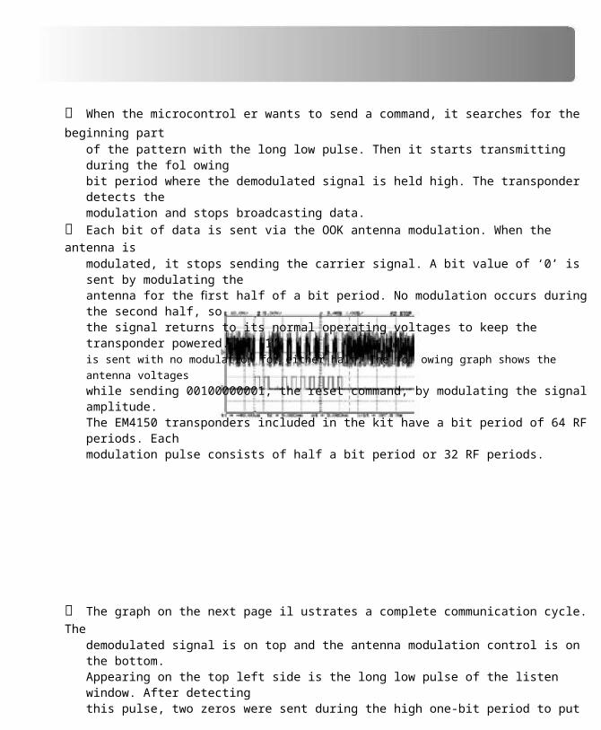
When the microcontrol er wants to send a command, it searches for the beginning partof the pattern with the long low pulse. Then it starts transmitting during the fol owingbit period where the demodulated signal is held high. The transponder detects themodulation and stops broadcasting data.
Each bit of data is sent via the OOK antenna modulation. When the antenna ismodulated, it stops sending the carrier signal. A bit value of ‘0’ is sent by modulating theantenna for the first half of a bit period. No modulation occurs during the second half, sothe signal returns to its normal operating voltages to keep the transponder powered. A ‘1’is sent with no modulation for either half. The fol owing graph shows the antenna voltages
while sending 00100000001, the reset command, by modulating the signal amplitude.The EM4150 transponders included in the kit have a bit period of 64 RF periods. Eachmodulation pulse consists of half a bit period or 32 RF periods.
The graph on the next page il ustrates a complete communication cycle. Thedemodulated signal is on top and the antenna modulation control is on the bottom.Appearing on the top left side is the long low pulse of the listen window. After detectingthis pulse, two zeros were sent during the high one-bit period to put the transponder intolisten mode. The next eight bits are the command, which are fol owed by a parity bit. Thesend time is located between the two vertical dashed lines. Notice the extra time at theend when a ‘1’ was sent for parity. To complete the process, the transponder validatesthe command and sends an acknowledgment (ACK). The reader detects the emittedpattern to confirm a successful transmission. The ACK pattern begins within the secondlow pulse after the second vertical line and ends with the last high pulse.
RFID Exercise Book

9 READ/WRITE TRANSPONDER
(CONT.)
Create ex9.c and type in the fol owing source code:
#include <rfi d.h>
#include <rs485.c>
#include <em4095.c>
#include <em4150.c>
#include <stdlib.h>
int8 msg[32];
#include “utilities.c”
void main() {
int8 err;
int32 temp;
rs485_init();
rf_init(); // Initialize the RF reader
output_low(GREEN_LED); // Show the board is powered and ready
sprintf(msg, “\n\n\rR,W: “);for(;;) { // Choose read or write
RS485send(msg);
(continued...)

CCS, Inc.

(continued...)switch(toupper(RS485getc())) {
case ‘R’:
sprintf(msg, “\n\rAddress (0-33): “); // Get an address
if((err = read_4150(msg, RS485getInt())) == ERR_OK) {RS485send(msg);
temp = make32(msg[3], msg[2], msg[1], msg[0]);
sprintf(msg, “\n\rData: %lu”, temp);
RS485send(msg);
break;}
sprintf(msg, “\n\rAddress (0-33): “); // Get an addresscase ‘W’:
RS485send(msg);
temp = RS485getInt();
sprintf(msg, “\n\rData: “); // Get data to write
err = write_4150(RS485getI32(), temp); RS485send(msg);
break;
default: continue;
switch(err) {}
case ERR_OK: sprintf(msg, “\n\rOK”); break;
case ERR_LIW: sprintf(msg, “\n\rLIW”); break;
case ERR_NAK: sprintf(msg, “\n\rNAK”); break;
case ERR_PARITY: sprintf(msg, “\n\rPARITY”); break;
} RS485send(msg);
}
}
Compile the program and download it to the RFID board. Once running, place anEM4150 transponder near the antenna and test the program. The characters sent tothe RFID board wil not be displayed without local echo enabled in SIOW. Since thetransponder is new, al EEPROM should fi rst contain 0. Try reading addresses 32 and 33to see the device serial and identifi cation numbers.
The last switch statement examines the error code returned by the transponder functions.

Different error codes are available to let software know what is causing a problem andhandle it as necessary.
RFID Exercise Book

10 ADVANCED READ/WRITETRANSPONDER
As mentioned in the previous chapter, the read/write transponder included in the kit
offers read, write, and password protection. Create a fi le called EX10.C, copy over al the
source code from EX8.C, and add the fol owing input options:
sprintf(msg, “\n\rPassword: “);case ‘L’:
RS485send(msg);
err = login_4150(RS485getI32());
break;
sprintf(msg, “\n\rOld PW: “);case ‘C’:
RS485send(msg);
temp = RS485getI32();
sprintf(msg, “\n\rNew PW: “);
// Get login password
// Get old password
// Get new password
err = setPassword_4150(temp, RS485getI32()); RS485send(msg);
break;
sprintf(msg, “\n\rFirst: “);case ‘P’: // First read protected word
RS485send(msg);
temp = RS485getInt();
sprintf(msg, “\n\rLast: “); // Last read protected word
err = readProtect_4150(temp, RS485getInt()); RS485send(msg);
case ‘E’: err = PWprotect_4150(TRUE); break; break;
case ‘D’: err = PWprotect_4150(FALSE); break;
case ‘T’: err = reset_4150(); break;
Add the fol owing cases to the error-checking switch statement:
case ERR_NAK_OLDPW: sprintf(msg, “\n\rNAK OPW”); break;
case ERR_NAK_NEWPW: sprintf(msg, “\n\rNAK NPW”); break;
case ERR_LIW_NEWPW: sprintf(msg, “\n\rLIW NPW”); break;

CCS, Inc.

Change sprintf (msg, “\n\n\rR,W: “); to include L,C,P,E,D,T.
Compile the program and download it to the control er board. Place an EM4150
transponder near the antenna and press ‘L’ to login. The default password is zero. Oncea successful login has occurred, the read-protected region may be modified. Press ‘P’and read protect five through ten. Write some data to address seven and read it back.Move the transponder away from the antenna so it loses power, then return it to the RFfield. A read to address seven will return zero. Write some data to address six and readit back. It will also read zero. Log back in, and read addresses six and seven again. Thisdemonstration shows how read protection works. It al ows a write to occur anytime, butdata can only be read after a successful login. Write-protection works a little differently.In order to change the data in a write-protected word, write-protection must first beremoved from that address.
While logged in, press ‘E’ to enable password-protection, then ‘T’ to reset. A reset issimilar to removing and replacing the transponder from the RF field. Now an error wiloccur when trying to write to any location. Log back in to gain write access and try writingsome data once more.
Try experimenting on your own. Be careful not to lose the password if it is changed. Openem4150.c and explore some other options as wel .
RFID Exercise Book

11 ANTI-COLLISION
The transponders provided in the kit only permit one transponder in the RF fi eld at a time.
They always broadcast data while powered and respond to every command they receive.When two or more transmit at the same, their signals wil interfere with each other,preventing any communication. Try reading the read/write transponder with the read-onlytransponder in the fi eld at the same time to witness the effect. The single transponderscheme is suffi cient for many applications, such as access control; however, sometimesit is necessary to read multiple transponders at once. Some example situations includereading an entire pallet of items or a continuous stream of packages.
There are many algorithms for handling multiple transponders in a single RF fi eld, aslong as the transponders support anti-col ision. Some algorithms work better for certainsituations. Described below is one algorithm for read-only anti-col ision and one for read/write anti-col ision.
This method is suited for read-only transponders. Each transponder contains a randomnumber clock generator and a random number clock counter. Unlike the transpondersin the kit, these do not transmit when powered until they see a gap in the RF fi eld. Atthis time, they begin their random number generation, wait for a given period, thenbegin to transmit. Upon seeing the second gap, they stop their random number circuitand save the current number. Each gap in the RF fi eld causes the saved number tobe decremented. Once it reaches zero, the transponder transmits its data. Since eachtransponder has a different random number, there are no col isions. The reader controlscommunication by providing the RF gaps. If the reader notices a col ision while reading,it ignores the data and provides another gap. Otherwise the reader attempts to readthe data until successful, and then sends another gap. It would be very diffi cult tosynchronize two-way communication with this method, so a different approach is usedfor some read/write transponders.
One read/write algorithm begins with all transponders enabled at power on. Whentransponders are enabled they wil respond to commands, but not continuouslybroadcast. The process starts with the reader sending a read command. If the readernotices a col ision, it starts the arbitration process by sending the arbitration command.Each tag responds with its least signifi cant address bit. The tags with a ‘0’ respondimmediately and tags with a ‘1’ wait a moment before sending; this avoids col isions.The reader checks if it received a 0, 1, or 0 and 1. If the reader reads a 0, it respondswith a 0. If it received only a 1, it responds with a 1. The transponders that sent amatching address bit continue the process by sending their next address bit. The cyclecontinues until the most signifi cant address bit is read. The entire process identifi es theaddress of one transponder. The reader disables this transponder and continues to fi ndaddresses until no more col isions occur. Now the reader can enable a transponder andcommunicate without interference.
CCS, Inc.


12 RFID RESOURCES
There are many websites with great information about RFID technology, products, and design. Many manufacturers provide product information along with technology descriptions.
The RFID Handbook is located at www.rfi d-handbook.com. This is an in-depth book discussing everything about RFID. The site offers a forum and a free preview of one chapter in the book.The RFID Journal is located at www.rfi djournal.com. This site contains RFID news, case studies, ideas, and opinions. Some articles are free, while others require a paid subscription.
EM Microelectronic is located at www.emmicroelectronics.com. Manufacturers of transponders in this kit. See their website for datasheets, application guides, different transponders, and other information.
Escort Memory Systems is located at www.ems-rfi d.com. They are another company that offers information about RFID and a variety of transponders and readers.
RFID Updates are located at www.rfi dupdate.com. This site contains daily news posting related to RFID.
RFID Talk is located at www.rfi dtalk.com. This site is a forum discussing design advice, news, jobs, and general information about RFID.
Links to RFID privacy articles are located at www.rfi dprivacy.org. This site provides articles and information that explore the issue of privacy as RFID becomes more integrated into our society.
On The Web
Comprehensive list of PICmicro®
Development tools and information
Microchip Home Page
CCS Compiler/Tools Home Page
www.pic-c.com/links
www.microchip.com
www.ccsinfo.com
CCS Compiler/Tools Software Update Page www.ccsinfo.com
click: Support → Downloads
C Compiler User Message Exchange
Device Datasheets List
C Compiler Technical Support
www.ccsinfo.com/forum
www.ccsinfo.com
click: Support → Device Datasheets
RFID Exercise Book

EMULATORS
Other Development Tools
The ICD used in this booklet uses two I/O pins on the chip to communicate with a small debugprogram in the chip. This is a basic debug tool that takes up some of the chip’s resources (I/Opins and memory). An emulator replaces the chip with a special connector that connects to a unitthat emulates the chip. The debugging works in a simulator manner except that the chip has all ofits normal resources, the debugger runs faster and there are more debug features. For examplean emulator typically will allow any number of breakpoints. Some of the emulators can break onan external event like some signal on the target board changing. Some emulators can break onan external event like some that were executed before a breakpoint was reached. Emulators costbetween $500 and $3000 depending on the chips they cover and the features.
DEVICE PROGRAMMERS The ICD can be used to program FLASH chips as was done in these exercises. A stand alonedevice programmer may be used to program all the chips. These programmers will use the .HEXfile output from the compiler to do the programming. Many standard EEPROM programmers doknow how to program the Microchip parts. There are a large number of Microchip only deviceprogrammers in the $100-$200 price range. Note that some chips can be programmed once(OTP) and some parts need to be erased under a UV light before they can be re-programmed(Windowed). CCS offers the Mach X which is a stand-alone programmer and can be used as anin-circuit debugger.
PROTOTYPING BOARDS There are a large number of Prototyping boards available from a number of sources. Somehave an ICD interface and others simply have a socket for a chip that is externally programmed. Some boards have some advanced functionality on the board to help design complex software.For example, CCS has a Prototyping board with a full 56K modem on board and a TCP/IP stackchip ready to run internet applications such as an e-mail sending program or a mini web server.Another Prototyping board from CCS has a USB interface chip, making it easy to start developing
USB application programs.
SIMULATORS A simulator is a program that runs on the PC and pretends to be a microcontroller chip. A simulator offers all the normal debug capability such as single stepping and looking at variables,however there is no interaction with real hardware. This works well if you want to test a mathfunction but not so good if you want to test an interface to another chip. With the availability of lowcost tools, such as the ICD in this kit, there is less interest in simulators. Microchip offers a freesimulator that can be downloaded from their web site. Some other vendors offer simulators as apart of their development packages.
RFID Board
���
�����
�����
������
������
��
��
��
��
��
��
����
���
���
��
����
�
������
�����������
�������������

��������������������
������������
��
��
��
����
����
������������������������������������������������������������
RS
-
48
5 Board���������
������������ �
���������

