rfid asd kit+library asd kit+library uhf rfid simulations - identification performance in dependence...
TRANSCRIPT

CISC Semiconductor Design+Consulting GmbH | Lakeside B07, 9020 Klagenfurt, Austria | www.cisc.at
RFID ASD Kit+Library
UUHHFF RRFFIIDD SSiimmuullaattiioonnss --
IIddeennttiiffiiccaattiioonn ppeerrffoorrmmaannccee iinn
ddeeppeennddeennccee oonn UUIIII ssiizzee
EVALUATION REPORT
Project: UMIC0901
Document No: UMIC0901-R20
Issue: 2009-12-10

Project: UMIC0901
Evaluation Report Doc. No.: UMIC0901-R20
Issue: 2009-12-10
UHF RFID Simulations - Identification performance in dependence on UII size
© 2009 CISC Semiconductor Design+Consulting GmbH Page 2 of 59
.
CONTENTS
1 EXECUTIVE SUMMARY 4
2 INTRODUCTION 4
3 SIMULATION SETUP 5
3.1 Simulation Architecture Description 5
3.2 Command Sequence 5
3.3 Parameter Settings 7
3.3.1 General Parameters 7
3.3.2 Batch Packages 9
4 TERMS AND DEFINITIONS 10
4.1 Terms 10
4.2 Abbreviations 11
5 RESULT EVALUATION 11
5.1 Homogeneous Tag Populations 11
5.1.1 Batch 1 11 5.1.1.1 Full Detection Time 11 5.1.1.2 Full Read Time 13 5.1.1.3 All Data Received 15 5.1.1.4 Anticollision Rate 17
5.1.2 Batch 2 19 5.1.2.1 Full Detection Time 19 5.1.2.2 Full Read Time 21 5.1.2.3 All Data Received 23 5.1.2.4 Anticollision Rate 24
5.1.3 Batch 3 26 5.1.3.1 Full Detection Time 26 5.1.3.2 Full Read Time 26 5.1.3.3 All Data Received 29 5.1.3.4 Anticollision Rate 30
5.1.4 Batch 4 32 5.1.4.1 Full Detection Time 32 5.1.4.2 Full Read Time 33 5.1.4.3 All Data Received 34 5.1.4.4 Anticollision Rate 35

Project: UMIC0901
Evaluation Report Doc. No.: UMIC0901-R20
Issue: 2009-12-10
UHF RFID Simulations - Identification performance in dependence on UII size
© 2009 CISC Semiconductor Design+Consulting GmbH Page 3 of 59
.
5.2 Mixed Tag Populations 37
5.2.1 Description of the Mixed Setup 37
5.2.2 Batch 5 37 5.2.2.1 Full Detection Time 37 5.2.2.2 Anticollision Rate 38
5.3 Further Observations and Implications 39
5.3.1 Reading User Memory at Different Link Rates 39
5.3.2 Different UII Lengths affecting the Overall Throughput 42
5.3.3 Possible Further Areas of Interest 43
6 CONCLUSION 44
7 ANNEX: SIMULATION RESULTS 45
7.1 Overview 45
7.1.1 Batch 1 45
7.1.2 Batch 2 46
7.1.3 Batch 3 48
7.1.4 Batch 4 49
7.1.5 Batch 5 50
7.2 Detailed Result Format Description 50
7.2.1 Files Created During the Simulation 50
7.2.2 Files Created After the Simulation for the Purpose of Evaluation 51
8 ANNEX: CORRELATION TO COMMERCIAL PRODUCTS 52
9 ANNEX: GLOBAL UHF RFID REGULATIONS 53
10 REFERENCES 56
11 DISCLAIMER 58
12 REVISION HISTORY 58

Project: UMIC0901
Evaluation Report Doc. No.: UMIC0901-R20
Issue: 2009-12-10
UHF RFID Simulations - Identification performance in dependence on UII size
© 2009 CISC Semiconductor Design+Consulting GmbH Page 4 of 59
.
1 EXECUTIVE SUMMARY
Based on simulations executed with the CISC RFID ASD Kit+Library for the UHF frequency range, the following key statements can be made in respect to the ISO/IEC 18000-6Amd1 Type C air interface under
consideration of ISO/IEC 15962 data syntax:
• Throughput in terms of Anticollision Rate degrades by approximately 30% if the UII length is
increased from 96 bits to 240 bits in the US regulatory dense interrogator environment. This has also a severe impact on mixed population environments of tags with 96 bit UII and 240 bit UII.
• User Memory can only be read in the course of tag anti-collision, which means that User Memory
handling always means significant decrease of application performance versus an application that requires no use of user memory.
• If User Memory needs to be supported for application specific reasons anyway, then the UII should
be kept short in order to have fast Anticollision Rate for mixed populations of tags and for those
tags where the read of the user memory can be skipped. For tags where the User Memory needs to be read in any case, there is no difference between having information in the UII memory bank
(MB01) or User Memory bank (MB11).
2 INTRODUCTION
This report contains the description and detailed analysis of the RFID communication simulations carried out for Michelin according the project offer DMIC0901-P1 issued by CISC Semiconductor.
The project covers the simulation and evaluation of a defined subset of the ISO/IEC 18000-6Amd1 Type C specification for UHF RFID (equivalent to EPCglobal Class-1 Generation-2) with focus on performance
considerations related to varying amounts of data stored in memory banks 012 and 112.
The structure of this report is as follows:
First, the simulation setup including the architecture of the selected simulation environment, simulated
command sequences and chosen parameter settings is described. The simulation setup is partitioned in several batch packages for convenience.
Second, terms and abbreviations required for understanding the simulation results provided in the following sections are explained.
Third, the simulation results are evaluated and conclusions are drawn.
Finally, an overview about the raw simulation output data is provided as an annex to this document and a brief description of the additional raw simulation data to be delivered under the scope of this project is
given.

Project: UMIC0901
Evaluation Report Doc. No.: UMIC0901-R20
Issue: 2009-12-10
UHF RFID Simulations - Identification performance in dependence on UII size
© 2009 CISC Semiconductor Design+Consulting GmbH Page 5 of 59
.
3 SIMULATION SETUP
3.1 Simulation Architecture Description
Based on the protocol implementations available in the CISC Application and System Design (ASD) Library a
customized simulation model was built on top of The MathWorks Matlab® and Simulink® according to the following basic concepts:
• Support of variable UII memory bank size
• Support of variable User memory bank size
• Flexible definition of the interrogator command sequence and tag response handling
o Adaptation of the implemented anticollision algorithm
� i.e. support of additional read access handling
o Adaptation of the corresponding tag state machine
Refer to www.cisc.at/asd for more details regarding the CISC RFID ASD Kit+Library.
3.2 Command Sequence
In order to enable evaluation of a pure tag inventory aiming at detecting all tags illuminated by
the RF field of the interrogator as well as more sophisticated scenarios combining tag inventory
with read access, the following command sequences have been simulated:
1. Inventory only (interrogator stops after receiving the UII)
o Select
o Query
o RN16
o Anticollision (QueryAdjust/QueryRep/NAK), if required
o ACK
o PC + UII + CRC16
2. Inventory + read access to user memory bank (read whole MB112 at once)
o Select
o Query
Project: UMIC0901
Evaluation Report Doc. No.: UMIC0901-R20
Issue: 2009-12-10
UHF RFID Simulations - Identification performance in dependence on UII size
© 2009 CISC Semiconductor Design+Consulting GmbH Page 6 of 59
.
o RN16 (or interference)
o Anticollision (QueryAdjust/QueryRep/NAK), if required
o ACK
o PC + UII + CRC16
o Req_RN
o RN16 handle
o Read
o Content of User Memory
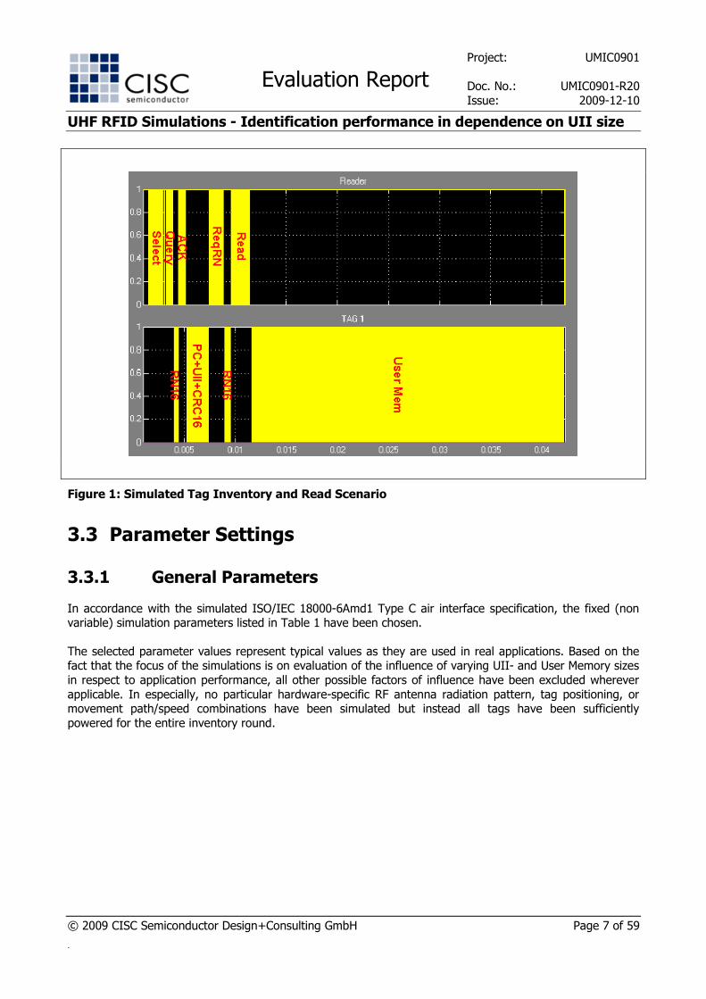
Figure 1 shows the mentioned sequence of interrogator commands and tag responses in
overview. In this particular example, a single tag is queried by the interrogator and no anti-collision
handling is required.
Project: UMIC0901
Evaluation Report Doc. No.: UMIC0901-R20
Issue: 2009-12-10
UHF RFID Simulations - Identification performance in dependence on UII size
© 2009 CISC Semiconductor Design+Consulting GmbH Page 7 of 59
.
Figure 1: Simulated Tag Inventory and Read Scenario
3.3 Parameter Settings
3.3.1 General Parameters
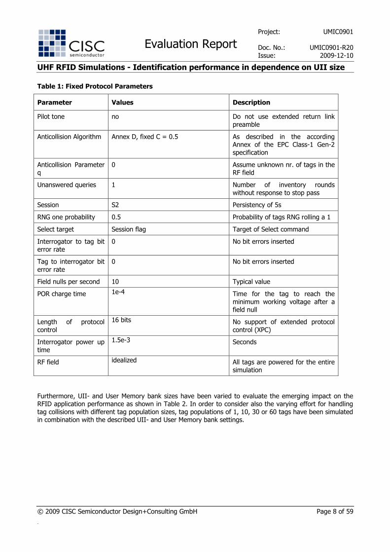
In accordance with the simulated ISO/IEC 18000-6Amd1 Type C air interface specification, the fixed (non variable) simulation parameters listed in Table 1 have been chosen.
The selected parameter values represent typical values as they are used in real applications. Based on the fact that the focus of the simulations is on evaluation of the influence of varying UII- and User Memory sizes
in respect to application performance, all other possible factors of influence have been excluded wherever
applicable. In especially, no particular hardware-specific RF antenna radiation pattern, tag positioning, or movement path/speed combinations have been simulated but instead all tags have been sufficiently
powered for the entire inventory round.
Project: UMIC0901
Evaluation Report Doc. No.: UMIC0901-R20
Issue: 2009-12-10
UHF RFID Simulations - Identification performance in dependence on UII size
© 2009 CISC Semiconductor Design+Consulting GmbH Page 8 of 59
.
Table 1: Fixed Protocol Parameters
Parameter Values Description
Pilot tone no Do not use extended return link
preamble
Anticollision Algorithm Annex D, fixed C = 0.5 As described in the according Annex of the EPC Class-1 Gen-2
specification
Anticollision Parameter q
0 Assume unknown nr. of tags in the RF field
Unanswered queries 1 Number of inventory rounds
without response to stop pass
Session S2 Persistency of 5s
RNG one probability 0.5 Probability of tags RNG rolling a 1
Select target Session flag Target of Select command
Interrogator to tag bit error rate
0 No bit errors inserted
Tag to interrogator bit
error rate
0 No bit errors inserted
Field nulls per second 10 Typical value
POR charge time 1e-4
Time for the tag to reach the
minimum working voltage after a field null
Length of protocol
control
16 bits No support of extended protocol
control (XPC)
Interrogator power up
time
1.5e-3
Seconds
RF field idealized All tags are powered for the entire simulation
Furthermore, UII- and User Memory bank sizes have been varied to evaluate the emerging impact on the RFID application performance as shown in Table 2. In order to consider also the varying effort for handling
tag collisions with different tag population sizes, tag populations of 1, 10, 30 or 60 tags have been simulated in combination with the described UII- and User Memory bank settings.

Project: UMIC0901
Evaluation Report Doc. No.: UMIC0901-R20
Issue: 2009-12-10
UHF RFID Simulations - Identification performance in dependence on UII size
© 2009 CISC Semiconductor Design+Consulting GmbH Page 9 of 59
.
Table 2: Variable Protocol Parameters
Parameter Values
UII Memory (MB 012)
User Memory (MB 112)
Sum
128 0 128
272 0 272
272 240 512
272 728 1000
128 144 272
128 384 512
Memory bank sizes
(in bits)
128 872 1000
1
10
30
Number of tags in the RF field
60
Please note that under the scope of this document always the full content of the according memory bank is quoted when referring to the UII- or User Memory. In detail, this means that a
UII Memory size of 128 bits corresponds to a 96-bit UII whereas a UII Memory Size of 272 bits corresponds to a 240-bit UII, see also 4.2.
Note: In case of MB112 = 0, the simulated command sequence does not include Req_RN nor Read. It is assumed that the interrogator inspects the UMI indicator to determine that no user memory is supported.
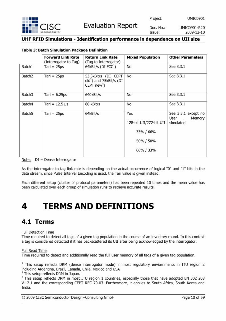
3.3.2 Batch Packages
To simplify the start and stop of the single simulation runs and to provide a convenient way of automatic simulation result evaluation, the different parameter setups have been partitioned in several different batch
simulation packages, see Table 3.
Project: UMIC0901
Evaluation Report Doc. No.: UMIC0901-R20
Issue: 2009-12-10
UHF RFID Simulations - Identification performance in dependence on UII size
© 2009 CISC Semiconductor Design+Consulting GmbH Page 10 of 59
.
Table 3: Batch Simulation Package Definition
Forward Link Rate (Interrogator to Tag)
Return Link Rate (Tag to Interrogator)
Mixed Population Other Parameters
Batch1 Tari = 25µs 64kBit/s (DI FCC1) No See 3.3.1
Batch2 Tari = 25µs 53.3kBit/s (DI CEPT old2) and 75kBit/s (DI
CEPT new3)
No See 3.3.1
Batch3 Tari = 6.25µs 640kBit/s No See 3.3.1
Batch4 Tari = 12.5 µs 80 kBit/s No See 3.3.1
Batch5 Tari = 25µs 64kBit/s Yes
128-bit UII/272-bit UII
33% / 66%
50% / 50%
66% / 33%
See 3.3.1 except no
User Memory
simulated
Note: DI = Dense Interrogator
As the interrogator to tag link rate is depending on the actual occurrence of logical "0" and "1" bits in the
data stream, since Pulse Interval Encoding is used, the Tari value is given instead.
Each different setup (cluster of protocol parameters) has been repeated 10 times and the mean value has been calculated over each group of simulation runs to retrieve accurate results.
4 TERMS AND DEFINITIONS
4.1 Terms
Full Detection Time
Time required to detect all tags of a given tag population in the course of an inventory round. In this context a tag is considered detected if it has backscattered its UII after being acknowledged by the interrogator.
Full Read Time
Time required to detect and additionally read the full user memory of all tags of a given tag population.
1 This setup reflects DRM (dense interrogator mode) in most regulatory enviornments in ITU region 2
including Argentina, Brazil, Canada, Chile, Mexico and USA 2 This setup reflects DRM in Japan. 3 This setup reflects DRM in most ITU region 1 countries, especially those that have adopted EN 302 208
V1.2.1 and the corresponding CEPT REC 70-03. Furthermore, it applies to South Africa, South Korea and India.
Project: UMIC0901
Evaluation Report Doc. No.: UMIC0901-R20
Issue: 2009-12-10
UHF RFID Simulations - Identification performance in dependence on UII size
© 2009 CISC Semiconductor Design+Consulting GmbH Page 11 of 59
.
Anticollision Time Time from the first tag detection until the last tag detection as logged by the interrogator.
Anticollision Rate
Theoretical number of tags that can be inventoried per second in a given RFID setup, calculated by using
the following expression: Total number of detections/Anticollision Time. All Data Received Time
Under the scope of this document this term denotes the time until all data stored on the tag has been
received by the interrogator. If the data is split between the UII- and the User Memory this requires backscattering of the UII Memory content as well as a separate read of the User Memory content. This key
figure is not at default implemented in the CISC RFID ASD Kit+Library products and has been added manually.
4.2 Abbreviations
ACR = Anticollision Rate (Tags/s)
FDT = Full Detection Time (s)
FRT = Full Read Time (s)
ADR = All data received (s)
UII Mem = UII memory bank (MB 012) size in bits; Comprises the full content of this memory bank, i.e.
CRC-16 checksum, Protocol Control (PC) bits, and the UII itself
Usr Mem = User memory bank (MB 112) size in bits
5 RESULT EVALUATION
5.1 Homogeneous Tag Populations
5.1.1 Batch 1
Batch simulation package 1 is a typical setup as it is used in FCC4 governed Dense Interrogator Mode
environments.
5.1.1.1 Full Detection Time
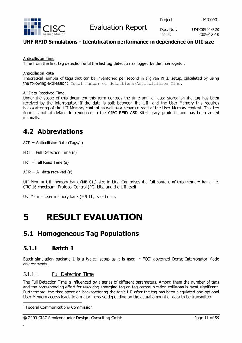
The Full Detection Time is influenced by a series of different parameters. Among them the number of tags and the corresponding effort for resolving emerging tag on tag communication collisions is most significant.
Furthermore, the time spent on backscattering the tag's UII after the tag has been singulated and optional
User Memory access leads to a major increase depending on the actual amount of data to be transmitted.
4 Federal Communications Commission

Project: UMIC0901
Evaluation Report Doc. No.: UMIC0901-R20
Issue: 2009-12-10
UHF RFID Simulations - Identification performance in dependence on UII size
© 2009 CISC Semiconductor Design+Consulting GmbH Page 12 of 59
.
Figure 2 shows how the time for detecting all tags within a population changes with the different UII- and
User Memory sizes.
Full Detection Time (all Tags detected, Link Rates: 25µs - 64kBit/s)
0
0.5
1
1.5
2
2.5
3
128 128 128 128 128 128 128 128 272 272 272 272 272 272 272 272
0 144 240 384 728 872 1776 1920 0 144 240 384 728 872 1776 1920
UII mem (bits)
Usr mem (bits)
Tim
e (s
) 1 Tag
10 Tags
30 Tags
60 Tags
Figure 2: Time Required to Detect all Tags
Additionally, Figure 3 is providing a detailed view on the data series regarding small tag populations of 1 and 10 tags respectively. It is visible that in case of simulating just 1 Tag, the only visible increase in respect to
the Full Detection Time is due to the increasing the UII length since the Full Detection Time is measured only until the last tag has transmitted its UII and the extra time to additionally read out its User Memory is
not considered per definition.
Project: UMIC0901
Evaluation Report Doc. No.: UMIC0901-R20
Issue: 2009-12-10
UHF RFID Simulations - Identification performance in dependence on UII size
© 2009 CISC Semiconductor Design+Consulting GmbH Page 13 of 59
.
Full Detection Time (Zoom: 1 Tag simulated, Link Rates: 25µs - 64kBit/s)
0
0.001
0.002
0.003
0.004
0.005
0.006
0.007
0.008
0.009
0.01
128 128 128 128 128 128 128 128 272 272 272 272 272 272 272 272
0 144 240 384 728 872 1776 1920 0 144 240 384 728 872 1776 1920
UII mem (bits)Usr mem (bits)
Tim
e (s
)
Step caused by transmission of longer UII
Full Detection Time (Zoom: 10 Tags simulated, Link Rates: 25µs - 64kBit/s)
0
0.05
0.1
0.15
0.20.25
0.30.35
0.4
0.45
0.5
128 128 128 128 128 128 128 128 272 272 272 272 272 272 272 272
0 144 240 384 728 872 1776 1920 0 144 240 384 728 872 1776 1920
UII mem (bits)Usr mem (bits)
Tim
e (s
)
Figure 3: Time Required to Detect all Tags - Details
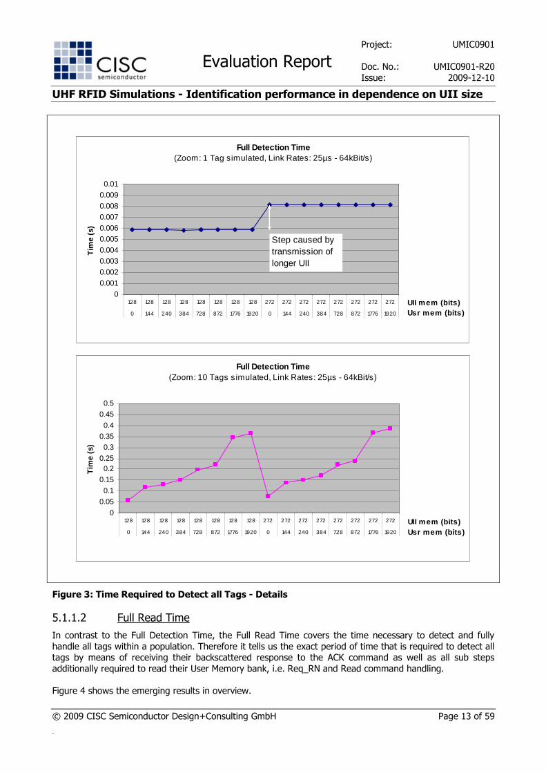
5.1.1.2 Full Read Time
In contrast to the Full Detection Time, the Full Read Time covers the time necessary to detect and fully
handle all tags within a population. Therefore it tells us the exact period of time that is required to detect all tags by means of receiving their backscattered response to the ACK command as well as all sub steps
additionally required to read their User Memory bank, i.e. Req_RN and Read command handling.
Figure 4 shows the emerging results in overview.
Project: UMIC0901
Evaluation Report Doc. No.: UMIC0901-R20
Issue: 2009-12-10
UHF RFID Simulations - Identification performance in dependence on UII size
© 2009 CISC Semiconductor Design+Consulting GmbH Page 14 of 59
.
Full Read Time (all Tags detected and Usr Mem read, Link Rates: 25µs - 64kBit/s)
0
0.5
1
1.5
2
2.5
3
128 128 128 128 128 128 128 128 272 272 272 272 272 272 272 272
0 144 240 384 728 872 1776 1920 0 144 240 384 728 872 1776 1920
UII mem (bits)
Usr mem (bits)
Tim
e (s
) 1 Tag
10 Tags
30 Tags
60 Tags
Figure 4: Time Required for Reading the User Memory of all Tags
If the results of Figure 4 are compared to the results of Figure 2, the extra-effort for reading the User Memory bank becomes obvious.
Figure 5 shows the comparison for the single tag scenario, where no anti-collision handling additionally
affects the results. The worst possible scenario in respect to the simulated parameter settings shows an additional time of 694% related to the Full Detection Time for reading the content of a User Memory of 1920
bits. Results for smaller User Memory banks show a smaller but still significant impact.

Project: UMIC0901
Evaluation Report Doc. No.: UMIC0901-R20
Issue: 2009-12-10
UHF RFID Simulations - Identification performance in dependence on UII size
© 2009 CISC Semiconductor Design+Consulting GmbH Page 15 of 59
.
Full Detection Time vs. Full Read Time(Zoom: 1 Tag simulated, Link Rates: 25µs - 64kBit/s)
0
0.005
0.01
0.015
0.020.025
0.030.035
0.04
0.045
0.05
128 128 128 128 128 128 128 128 272 272 272 272 272 272 272 272
0 144 240 384 728 872 1776 1920 0 144 240 384 728 872 1776 1920
UII mem (bits)Usr mem (bits)
Tim
e (s
)
All tags read
All tags detected
Additional time for reading user mem (+694%)
Figure 5: Difference between Full Detection Time and Full Read Time
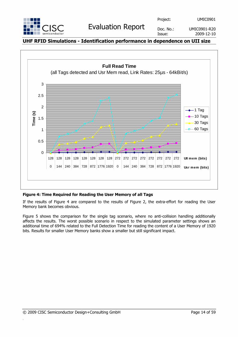
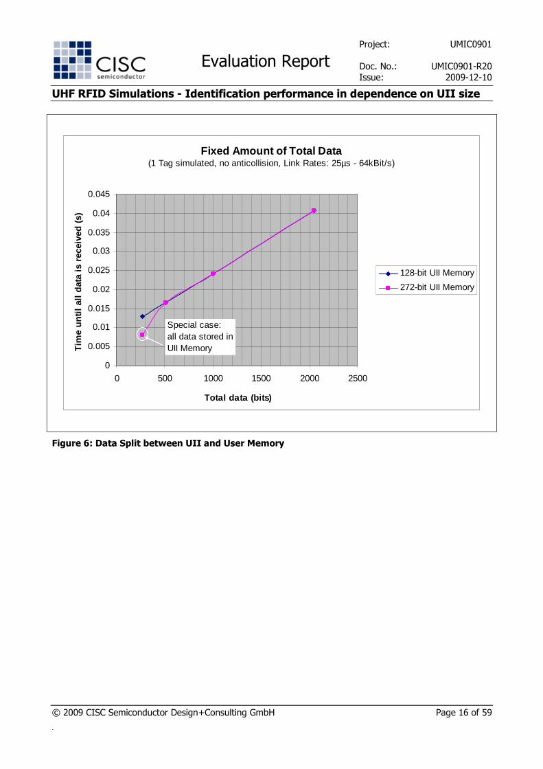
5.1.1.3 All Data Received
In some application scenarios a major design issue is to decide whether to put all data into the UII Memory or to split the data between UII Memory and User Memory, if possible.
Based on the results presented in the previous two sub-sections, we are able to investigate the time until all
data is received by the interrogator if a fixed total amount of data is assumed that is distributed between the two different memory banks. Figure 6 shows the results obtained for the batch simulation package 1.
In case of simulating a total amount of 272 bits of data, a major difference between the two different UII length settings is visible. If the 272 bits of application data are stored exclusively in the UII Memory no
further read access to the tag's User Memory is required. In this particular case the All Data Received Time equals the Full Detection Time and a major speedup is visible compared to the case where a 128-bit UII
Memory is assumed and the remaining 144 bits have to be stored in the User Memory (compare first data
points of the two series in Figure 6). This gap is caused by the extra time for requesting an access handle and issuing a separate Read command.
In all other cases, data is stored in the UII Memory as well as in the User Memory and results show that in this case no major difference between the simulations carried out with 128 and 272 bits of UII Memory can
be found. In other words, as soon as some data needs to be put into the User Memory the access method to
this memory bank itself causes some overhead that cannot be avoided. However, this overhead becomes less significant if the overall amount of data to be read increases. There is no major difference if some small
amount of user data is appended directly to the UII and the major amount of data is store in the User Memory and needs to be read separately, or if all user data is stored in the User Memory bank.
Project: UMIC0901
Evaluation Report Doc. No.: UMIC0901-R20
Issue: 2009-12-10
UHF RFID Simulations - Identification performance in dependence on UII size
© 2009 CISC Semiconductor Design+Consulting GmbH Page 16 of 59
.
Fixed Amount of Total Data (1 Tag simulated, no anticollision, Link Rates: 25µs - 64kBit/s)
0
0.005
0.01
0.015
0.02
0.025
0.03
0.035
0.04
0.045
0 500 1000 1500 2000 2500
Total data (bits)
Tim
e un
til a
ll da
ta is
rec
eive
d (s
)
128-bit UII Memory
272-bit UII Memory
Special case: all data stored in UII Memory
Figure 6: Data Split between UII and User Memory
Project: UMIC0901
Evaluation Report Doc. No.: UMIC0901-R20
Issue: 2009-12-10
UHF RFID Simulations - Identification performance in dependence on UII size
© 2009 CISC Semiconductor Design+Consulting GmbH Page 17 of 59
.
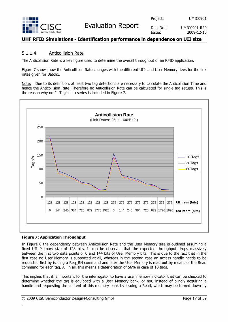
5.1.1.4 Anticollision Rate
The Anticollision Rate is a key figure used to determine the overall throughput of an RFID application.
Figure 7 shows how the Anticollision Rate changes with the different UII- and User Memory sizes for the link
rates given for Batch1.
Note: Due to its definition, at least two tag detections are necessary to calculate the Anticollision Time and hence the Anticollision Rate. Therefore no Anticollision Rate can be calculated for single tag setups. This is
the reason why no "1 Tag" data series is included in Figure 7.
Anticollision Rate(Link Rates: 25µs - 64kBit/s)
0
50
100
150
200
250
128 128 128 128 128 128 128 128 272 272 272 272 272 272 272 272
0 144 240 384 728 872 1776 1920 0 144 240 384 728 872 1776 1920
UII mem (bits)
Usr mem (bits)
Tag
s/s 10 Tags
30Tags
60Tags
Figure 7: Application Throughput
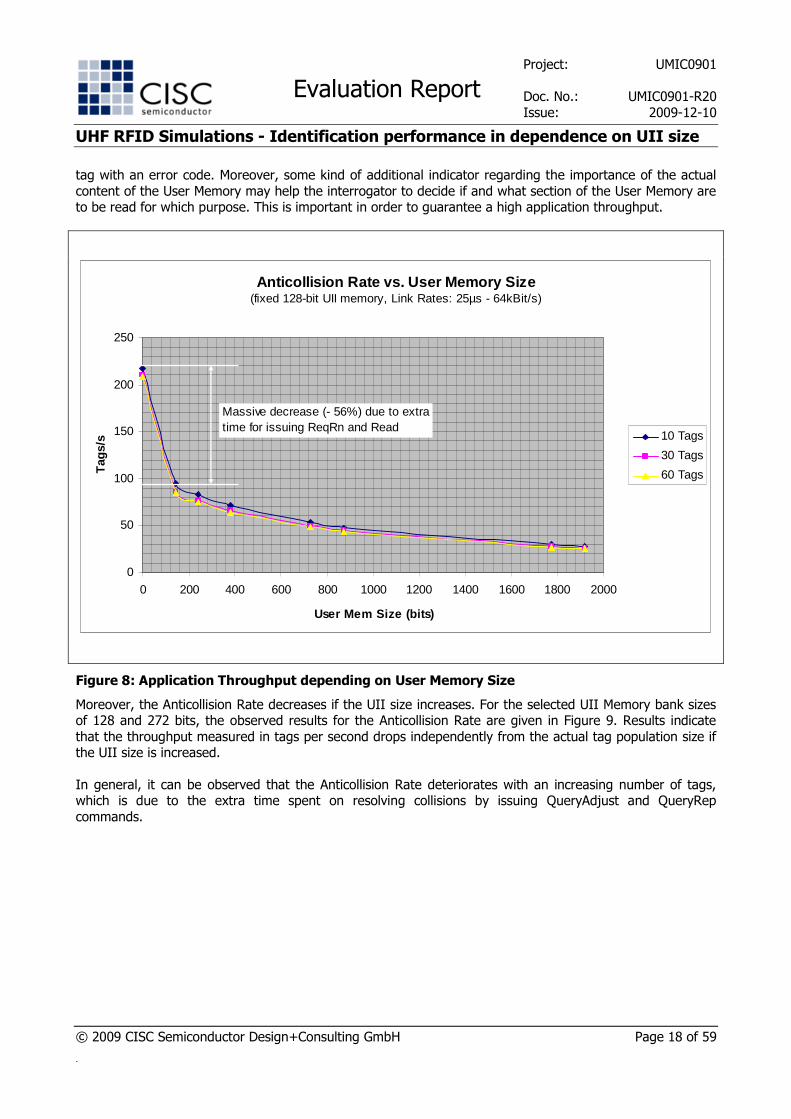
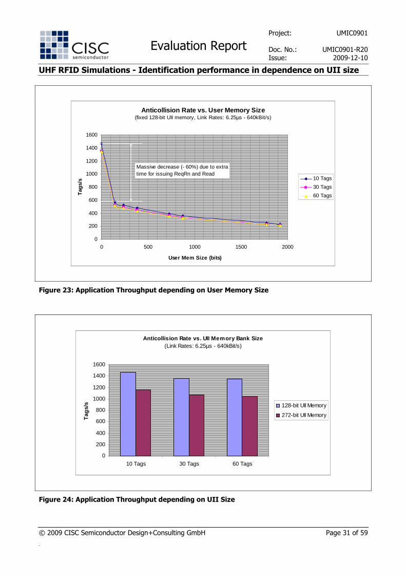
In Figure 8 the dependency between Anticollision Rate and the User Memory size is outlined assuming a fixed UII Memory size of 128 bits. It can be observed that the expected throughput drops massively
between the first two data points of 0 and 144 bits of User Memory bits. This is due to the fact that in the
first case no User Memory is supported at all, whereas in the second case an access handle needs to be requested first by issuing a Req_RN command and later the User Memory is read out by means of the Read
command for each tag. All in all, this means a deterioration of 56% in case of 10 tags.
This implies that it is important for the interrogator to have a user memory indicator that can be checked to
determine whether the tag is equipped with a User Memory bank, or not, instead of blindly acquiring a handle and requesting the content of this memory bank by issuing a Read, which may be turned down by
Project: UMIC0901
Evaluation Report Doc. No.: UMIC0901-R20
Issue: 2009-12-10
UHF RFID Simulations - Identification performance in dependence on UII size
© 2009 CISC Semiconductor Design+Consulting GmbH Page 18 of 59
.
tag with an error code. Moreover, some kind of additional indicator regarding the importance of the actual
content of the User Memory may help the interrogator to decide if and what section of the User Memory are to be read for which purpose. This is important in order to guarantee a high application throughput.
Anticollision Rate vs. User Memory Size(fixed 128-bit UII memory, Link Rates: 25µs - 64kBit/s)
0
50
100
150
200
250
0 200 400 600 800 1000 1200 1400 1600 1800 2000
User Mem Size (bits)
Tag
s/s 10 Tags
30 Tags
60 Tags
Massive decrease (- 56%) due to extra time for issuing ReqRn and Read
Figure 8: Application Throughput depending on User Memory Size
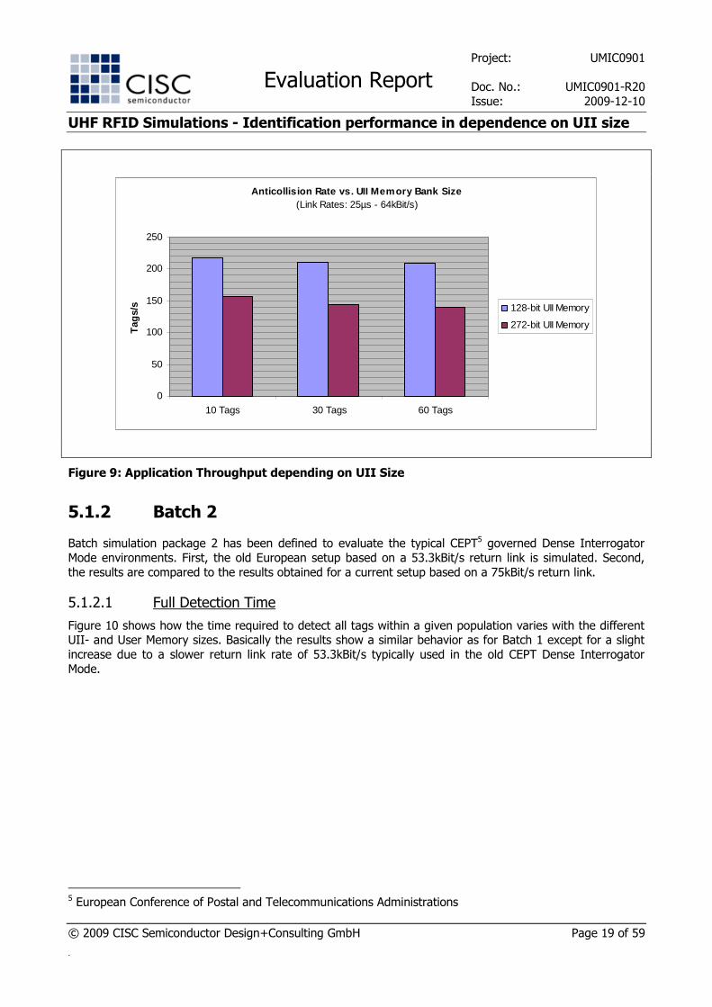
Moreover, the Anticollision Rate decreases if the UII size increases. For the selected UII Memory bank sizes of 128 and 272 bits, the observed results for the Anticollision Rate are given in Figure 9. Results indicate
that the throughput measured in tags per second drops independently from the actual tag population size if the UII size is increased.
In general, it can be observed that the Anticollision Rate deteriorates with an increasing number of tags, which is due to the extra time spent on resolving collisions by issuing QueryAdjust and QueryRep
commands.
Project: UMIC0901
Evaluation Report Doc. No.: UMIC0901-R20
Issue: 2009-12-10
UHF RFID Simulations - Identification performance in dependence on UII size
© 2009 CISC Semiconductor Design+Consulting GmbH Page 19 of 59
.
Anticollision Rate vs. UII Memory Bank Size(Link Rates: 25µs - 64kBit/s)
0
50
100
150
200
250
10 Tags 30 Tags 60 Tags
Tag
s/s 128-bit UII Memory
272-bit UII Memory
Figure 9: Application Throughput depending on UII Size
5.1.2 Batch 2
Batch simulation package 2 has been defined to evaluate the typical CEPT5 governed Dense Interrogator
Mode environments. First, the old European setup based on a 53.3kBit/s return link is simulated. Second,
the results are compared to the results obtained for a current setup based on a 75kBit/s return link.
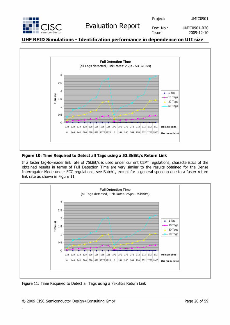
5.1.2.1 Full Detection Time
Figure 10 shows how the time required to detect all tags within a given population varies with the different UII- and User Memory sizes. Basically the results show a similar behavior as for Batch 1 except for a slight
increase due to a slower return link rate of 53.3kBit/s typically used in the old CEPT Dense Interrogator
Mode.
5 European Conference of Postal and Telecommunications Administrations
Project: UMIC0901
Evaluation Report Doc. No.: UMIC0901-R20
Issue: 2009-12-10
UHF RFID Simulations - Identification performance in dependence on UII size
© 2009 CISC Semiconductor Design+Consulting GmbH Page 20 of 59
.
Full Detection Time (all Tags detected, Link Rates: 25µs - 53.3kBit/s)
0
0.5
1
1.5
2
2.5
3
128 128 128 128 128 128 128 128 272 272 272 272 272 272 272 272
0 144 240 384 728 872 1776 1920 0 144 240 384 728 872 1776 1920
UII mem (bits)
Usr mem (bits)
Tim
e (s
) 1 Tag
10 Tags
30 Tags
60 Tags
Figure 10: Time Required to Detect all Tags using a 53.3kBit/s Return Link
If a faster tag-to-reader link rate of 75kBit/s is used under current CEPT regulations, characteristics of the
obtained results in terms of Full Detection Time are very similar to the results obtained for the Dense Interrogator Mode under FCC regulations, see Batch1, except for a general speedup due to a faster return
link rate as shown in Figure 11.
Full Detection Time (all Tags detected, Link Rates: 25µs - 75kBit/s)
0
0.5
1
1.5
2
2.5
3
128 128 128 128 128 128 128 128 272 272 272 272 272 272 272 272
0 144 240 384 728 872 1776 1920 0 144 240 384 728 872 1776 1920
UII mem (bits)
Usr mem (bits)
Tim
e (s
) 1 Tag
10 Tags
30 Tags
60 Tags
Figure 11: Time Required to Detect all Tags using a 75kBit/s Return Link
Project: UMIC0901
Evaluation Report Doc. No.: UMIC0901-R20
Issue: 2009-12-10
UHF RFID Simulations - Identification performance in dependence on UII size
© 2009 CISC Semiconductor Design+Consulting GmbH Page 21 of 59
.
5.1.2.2 Full Read Time
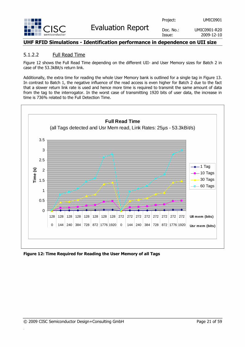
Figure 12 shows the Full Read Time depending on the different UII- and User Memory sizes for Batch 2 in case of the 53.3kBit/s return link.
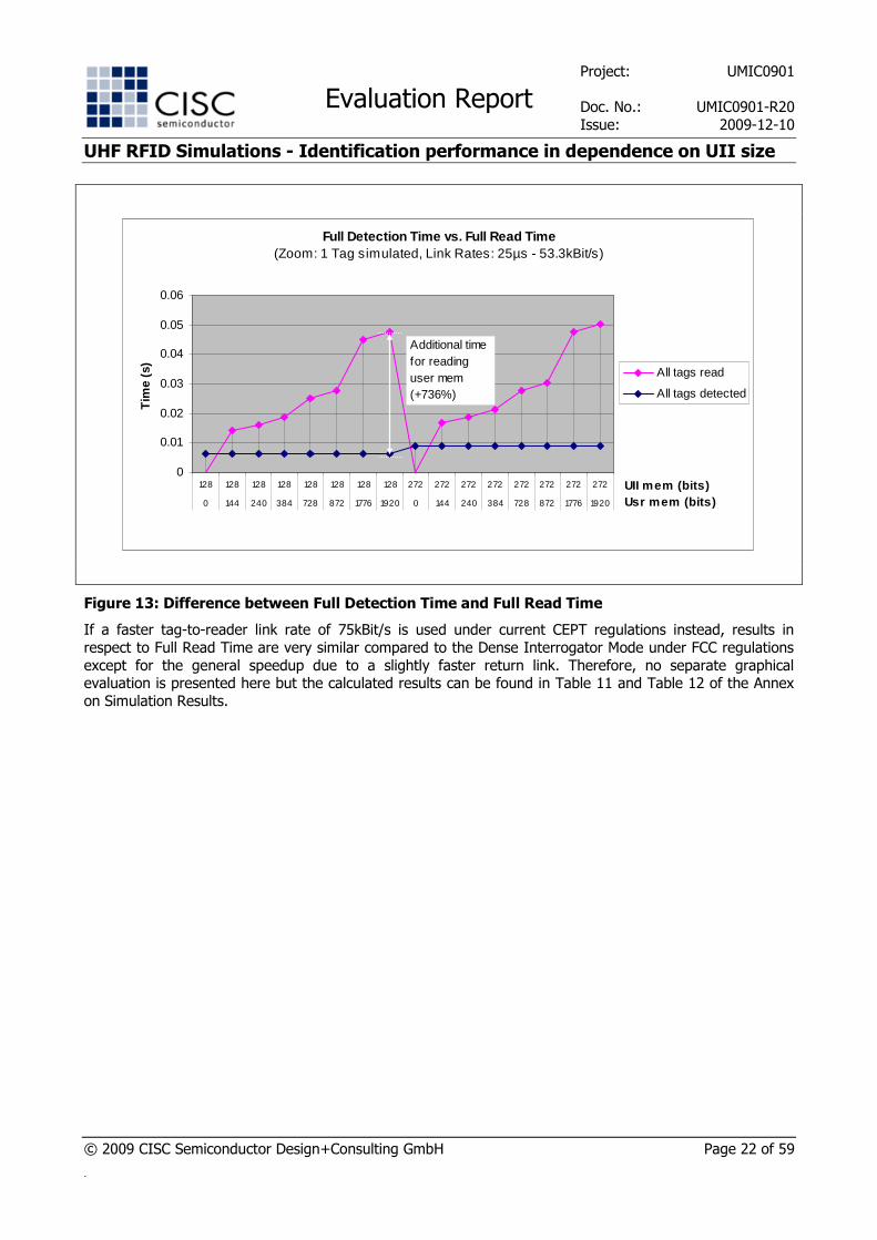
Additionally, the extra time for reading the whole User Memory bank is outlined for a single tag in Figure 13.
In contrast to Batch 1, the negative influence of the read access is even higher for Batch 2 due to the fact that a slower return link rate is used and hence more time is required to transmit the same amount of data
from the tag to the interrogator. In the worst case of transmitting 1920 bits of user data, the increase in time is 736% related to the Full Detection Time.
Full Read Time (all Tags detected and Usr Mem read, Link Rates: 25µs - 53.3kBit/s)
0
0.5
1
1.5
2
2.5
3
3.5
128 128 128 128 128 128 128 128 272 272 272 272 272 272 272 272
0 144 240 384 728 872 1776 1920 0 144 240 384 728 872 1776 1920
UII mem (bits)
Usr mem (bits)
Tim
e (s
) 1 Tag
10 Tags
30 Tags
60 Tags
Figure 12: Time Required for Reading the User Memory of all Tags
Project: UMIC0901
Evaluation Report Doc. No.: UMIC0901-R20
Issue: 2009-12-10
UHF RFID Simulations - Identification performance in dependence on UII size
© 2009 CISC Semiconductor Design+Consulting GmbH Page 22 of 59
.
Full Detection Time vs. Full Read Time(Zoom: 1 Tag simulated, Link Rates: 25µs - 53.3kBit/s)
0
0.01
0.02
0.03
0.04
0.05
0.06
128 128 128 128 128 128 128 128 272 272 272 272 272 272 272 272
0 144 240 384 728 872 1776 1920 0 144 240 384 728 872 1776 1920
UII mem (bits)Usr mem (bits)
Tim
e (s
)
All tags read
All tags detected
Additional time for reading user mem (+736%)
Figure 13: Difference between Full Detection Time and Full Read Time
If a faster tag-to-reader link rate of 75kBit/s is used under current CEPT regulations instead, results in
respect to Full Read Time are very similar compared to the Dense Interrogator Mode under FCC regulations
except for the general speedup due to a slightly faster return link. Therefore, no separate graphical evaluation is presented here but the calculated results can be found in Table 11 and Table 12 of the Annex
on Simulation Results.
Project: UMIC0901
Evaluation Report Doc. No.: UMIC0901-R20
Issue: 2009-12-10
UHF RFID Simulations - Identification performance in dependence on UII size
© 2009 CISC Semiconductor Design+Consulting GmbH Page 23 of 59
.
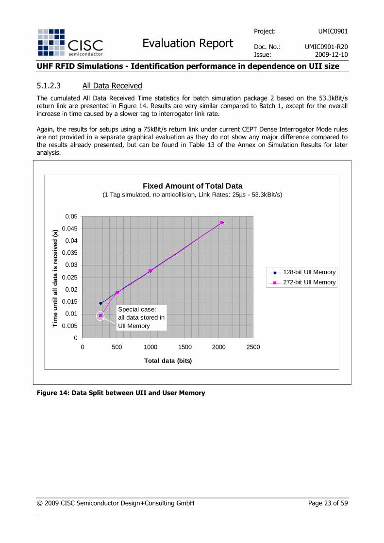
5.1.2.3 All Data Received
The cumulated All Data Received Time statistics for batch simulation package 2 based on the 53.3kBit/s return link are presented in Figure 14. Results are very similar compared to Batch 1, except for the overall
increase in time caused by a slower tag to interrogator link rate.
Again, the results for setups using a 75kBit/s return link under current CEPT Dense Interrogator Mode rules are not provided in a separate graphical evaluation as they do not show any major difference compared to
the results already presented, but can be found in Table 13 of the Annex on Simulation Results for later analysis.
Fixed Amount of Total Data (1 Tag simulated, no anticollision, Link Rates: 25µs - 53.3kBit/s)
0
0.005
0.01
0.015
0.02
0.025
0.03
0.035
0.04
0.045
0.05
0 500 1000 1500 2000 2500
Total data (bits)
Tim
e un
til a
ll da
ta is
rec
eive
d (s
)
128-bit UII Memory
272-bit UII Memory
Special case: all data stored in UII Memory
Figure 14: Data Split between UII and User Memory
Project: UMIC0901
Evaluation Report Doc. No.: UMIC0901-R20
Issue: 2009-12-10
UHF RFID Simulations - Identification performance in dependence on UII size
© 2009 CISC Semiconductor Design+Consulting GmbH Page 24 of 59
.
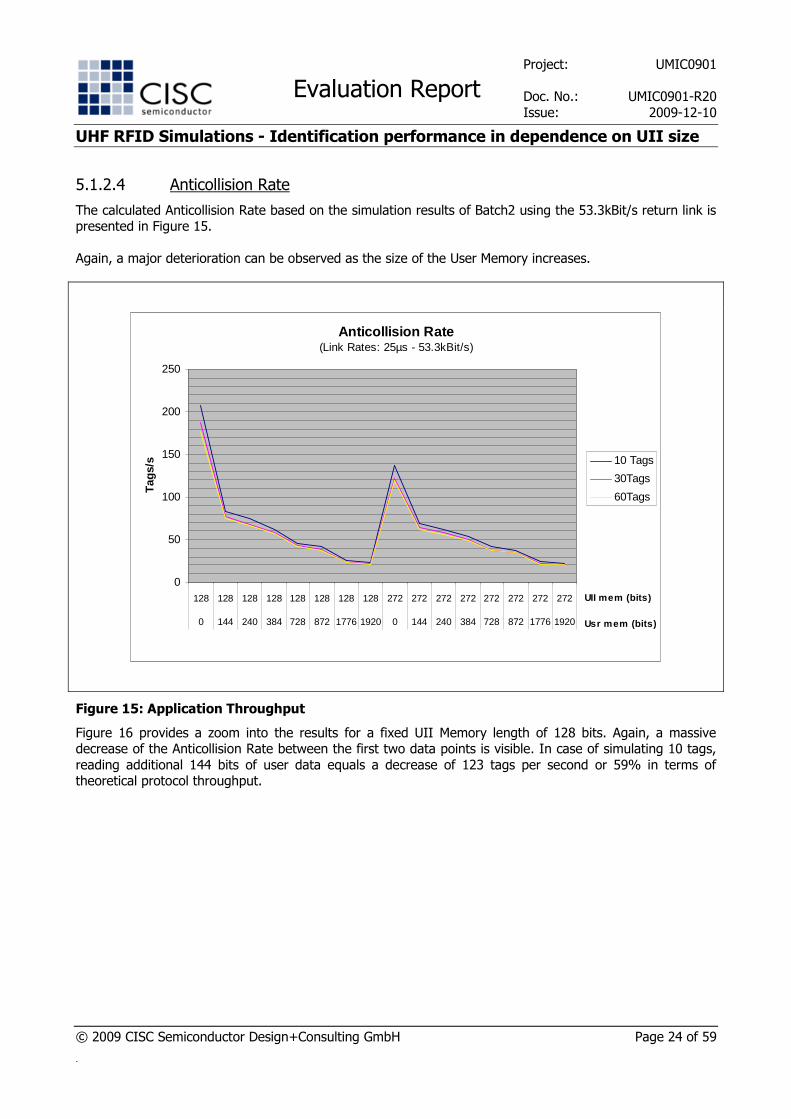
5.1.2.4 Anticollision Rate
The calculated Anticollision Rate based on the simulation results of Batch2 using the 53.3kBit/s return link is presented in Figure 15.
Again, a major deterioration can be observed as the size of the User Memory increases.
Anticollision Rate(Link Rates: 25µs - 53.3kBit/s)
0
50
100
150
200
250
128 128 128 128 128 128 128 128 272 272 272 272 272 272 272 272
0 144 240 384 728 872 1776 1920 0 144 240 384 728 872 1776 1920
UII mem (bits)
Usr mem (bits)
Tag
s/s 10 Tags
30Tags
60Tags
Figure 15: Application Throughput
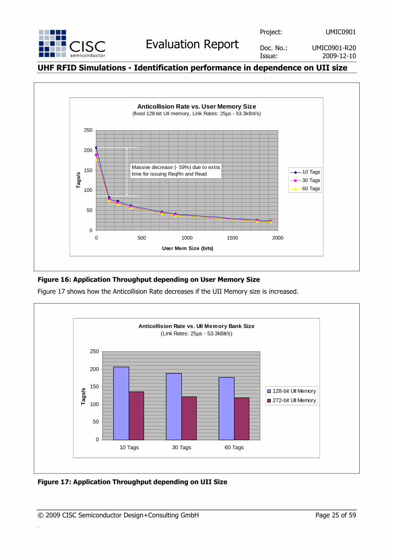
Figure 16 provides a zoom into the results for a fixed UII Memory length of 128 bits. Again, a massive decrease of the Anticollision Rate between the first two data points is visible. In case of simulating 10 tags,
reading additional 144 bits of user data equals a decrease of 123 tags per second or 59% in terms of theoretical protocol throughput.
Project: UMIC0901
Evaluation Report Doc. No.: UMIC0901-R20
Issue: 2009-12-10
UHF RFID Simulations - Identification performance in dependence on UII size
© 2009 CISC Semiconductor Design+Consulting GmbH Page 25 of 59
.
Anticollision Rate vs. User Memory Size(fixed 128-bit UII memory, Link Rates: 25µs - 53.3kBit/s)
0
50
100
150
200
250
0 500 1000 1500 2000
User Mem Size (bits)
Tag
s/s 10 Tags
30 Tags
60 Tags
Massive decrease (- 59%) due to extra time for issuing ReqRn and Read
Figure 16: Application Throughput depending on User Memory Size
Figure 17 shows how the Anticollision Rate decreases if the UII Memory size is increased.
Anticollision Rate vs. UII Memory Bank Size(Link Rates: 25µs - 53.3kBit/s)
0
50
100
150
200
250
10 Tags 30 Tags 60 Tags
Tag
s/s 128-bit UII Memory
272-bit UII Memory
Figure 17: Application Throughput depending on UII Size
Project: UMIC0901
Evaluation Report Doc. No.: UMIC0901-R20
Issue: 2009-12-10
UHF RFID Simulations - Identification performance in dependence on UII size
© 2009 CISC Semiconductor Design+Consulting GmbH Page 26 of 59
.
In case of the faster return link of 75.5kBit/s please refer to Table 11 and Table 12 of the Annex on
Simulation Results.
5.1.3 Batch 3
Batch simulation package 3 has been selected to simulate a high performance UHF RFID setup with high
forward and return link rates. This setup uses a 4 times higher forward data rate and a 10 times higher return link data rate than batch simulation package 1. This section contains an overview of the emerging results. Additionally, a comparison of Batch 1 and Batch 3 can be found in Section 5.3.
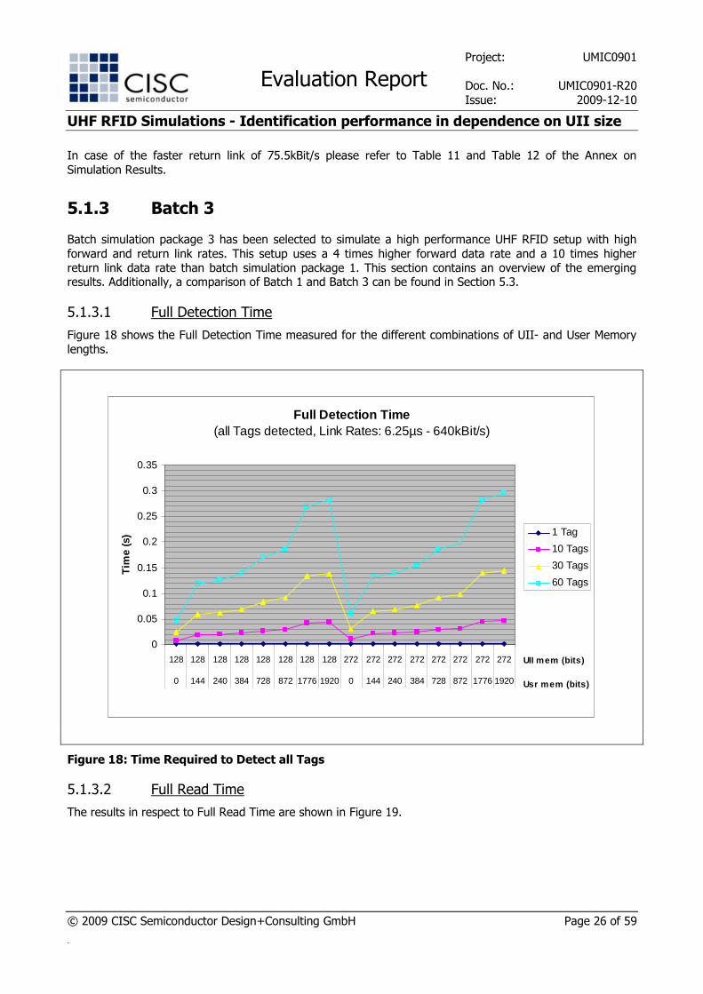
5.1.3.1 Full Detection Time
Figure 18 shows the Full Detection Time measured for the different combinations of UII- and User Memory
lengths.
Full Detection Time (all Tags detected, Link Rates: 6.25µs - 640kBit/s)
0
0.05
0.1
0.15
0.2
0.25
0.3
0.35
128 128 128 128 128 128 128 128 272 272 272 272 272 272 272 272
0 144 240 384 728 872 1776 1920 0 144 240 384 728 872 1776 1920
UII mem (bits)
Usr mem (bits)
Tim
e (s
) 1 Tag
10 Tags
30 Tags
60 Tags
Figure 18: Time Required to Detect all Tags
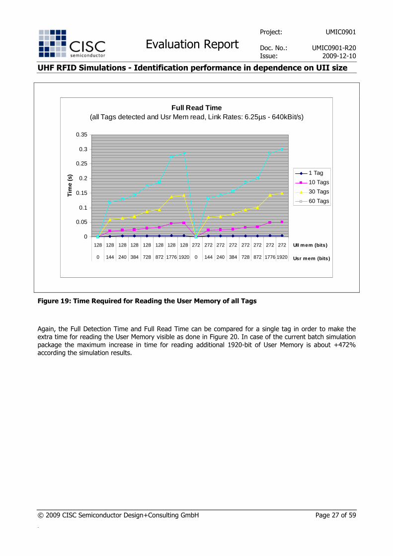
5.1.3.2 Full Read Time
The results in respect to Full Read Time are shown in Figure 19.
Project: UMIC0901
Evaluation Report Doc. No.: UMIC0901-R20
Issue: 2009-12-10
UHF RFID Simulations - Identification performance in dependence on UII size
© 2009 CISC Semiconductor Design+Consulting GmbH Page 27 of 59
.
Full Read Time (all Tags detected and Usr Mem read, Link Rates: 6.25µs - 640kBit/s)
0
0.05
0.1
0.15
0.2
0.25
0.3
0.35
128 128 128 128 128 128 128 128 272 272 272 272 272 272 272 272
0 144 240 384 728 872 1776 1920 0 144 240 384 728 872 1776 1920
UII mem (bits)
Usr mem (bits)
Tim
e (s
) 1 Tag
10 Tags
30 Tags
60 Tags
Figure 19: Time Required for Reading the User Memory of all Tags
Again, the Full Detection Time and Full Read Time can be compared for a single tag in order to make the extra time for reading the User Memory visible as done in Figure 20. In case of the current batch simulation
package the maximum increase in time for reading additional 1920-bit of User Memory is about +472% according the simulation results.

Project: UMIC0901
Evaluation Report Doc. No.: UMIC0901-R20
Issue: 2009-12-10
UHF RFID Simulations - Identification performance in dependence on UII size
© 2009 CISC Semiconductor Design+Consulting GmbH Page 28 of 59
.
Full Detection Time vs. Full Read Time(Zoom: 1 Tag simulated, Link Rates: 6.25µs - 640kBit/s)
0
0.001
0.002
0.003
0.004
0.005
0.006
128 128 128 128 128 128 128 128 272 272 272 272 272 272 272 272
0 144 240 384 728 872 1776 1920 0 144 240 384 728 872 1776 1920
UII mem (bits)Usr mem (bits)
Tim
e (s
)
All tags read
All tags detected
Additional time for reading user mem (+472%)
Figure 20: Difference between Full Detection Time and Full Read Time
Project: UMIC0901
Evaluation Report Doc. No.: UMIC0901-R20
Issue: 2009-12-10
UHF RFID Simulations - Identification performance in dependence on UII size
© 2009 CISC Semiconductor Design+Consulting GmbH Page 29 of 59
.
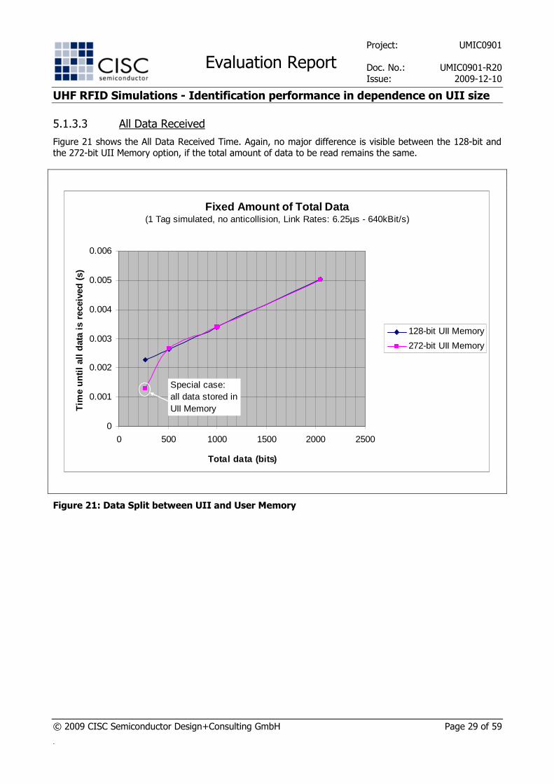
5.1.3.3 All Data Received
Figure 21 shows the All Data Received Time. Again, no major difference is visible between the 128-bit and the 272-bit UII Memory option, if the total amount of data to be read remains the same.
Fixed Amount of Total Data (1 Tag simulated, no anticollision, Link Rates: 6.25µs - 640kBit/s)
0
0.001
0.002
0.003
0.004
0.005
0.006
0 500 1000 1500 2000 2500
Total data (bits)
Tim
e un
til a
ll da
ta is
rec
eive
d (s
)
128-bit UII Memory
272-bit UII Memory
Special case: all data stored in UII Memory
Figure 21: Data Split between UII and User Memory

Project: UMIC0901
Evaluation Report Doc. No.: UMIC0901-R20
Issue: 2009-12-10
UHF RFID Simulations - Identification performance in dependence on UII size
© 2009 CISC Semiconductor Design+Consulting GmbH Page 30 of 59
.
5.1.3.4 Anticollision Rate
The Anticollision Rate for the current simulation package is presented in Figure 22, Figure 23, and Figure 24.
Anticollision Rate(Link Rates: 6.25µs - 640kBit/s)
0
200
400
600
800
1000
1200
1400
1600
128 128 128 128 128 128 128 128 272 272 272 272 272 272 272 272
0 144 240 384 728 872 1776 1920 0 144 240 384 728 872 1776 1920
UII mem (bits)
Usr mem (bits)
Tag
s/s 10 Tags
30Tags
60Tags
Figure 22: Application Throughput
Project: UMIC0901
Evaluation Report Doc. No.: UMIC0901-R20
Issue: 2009-12-10
UHF RFID Simulations - Identification performance in dependence on UII size
© 2009 CISC Semiconductor Design+Consulting GmbH Page 31 of 59
.
Anticollision Rate vs. User Memory Size(fixed 128-bit UII memory, Link Rates: 6.25µs - 640kBit/s)
0
200
400
600
800
1000
1200
1400
1600
0 500 1000 1500 2000
User Mem Size (bits)
Tag
s/s 10 Tags
30 Tags
60 Tags
Massive decrease (- 60%) due to extra time for issuing ReqRn and Read
Figure 23: Application Throughput depending on User Memory Size
Anticollision Rate vs. UII Memory Bank Size(Link Rates: 6.25µs - 640kBit/s)
0
200
400
600
800
1000
1200
1400
1600
10 Tags 30 Tags 60 Tags
Tag
s/s 128-bit UII Memory
272-bit UII Memory
Figure 24: Application Throughput depending on UII Size
Project: UMIC0901
Evaluation Report Doc. No.: UMIC0901-R20
Issue: 2009-12-10
UHF RFID Simulations - Identification performance in dependence on UII size
© 2009 CISC Semiconductor Design+Consulting GmbH Page 32 of 59
.
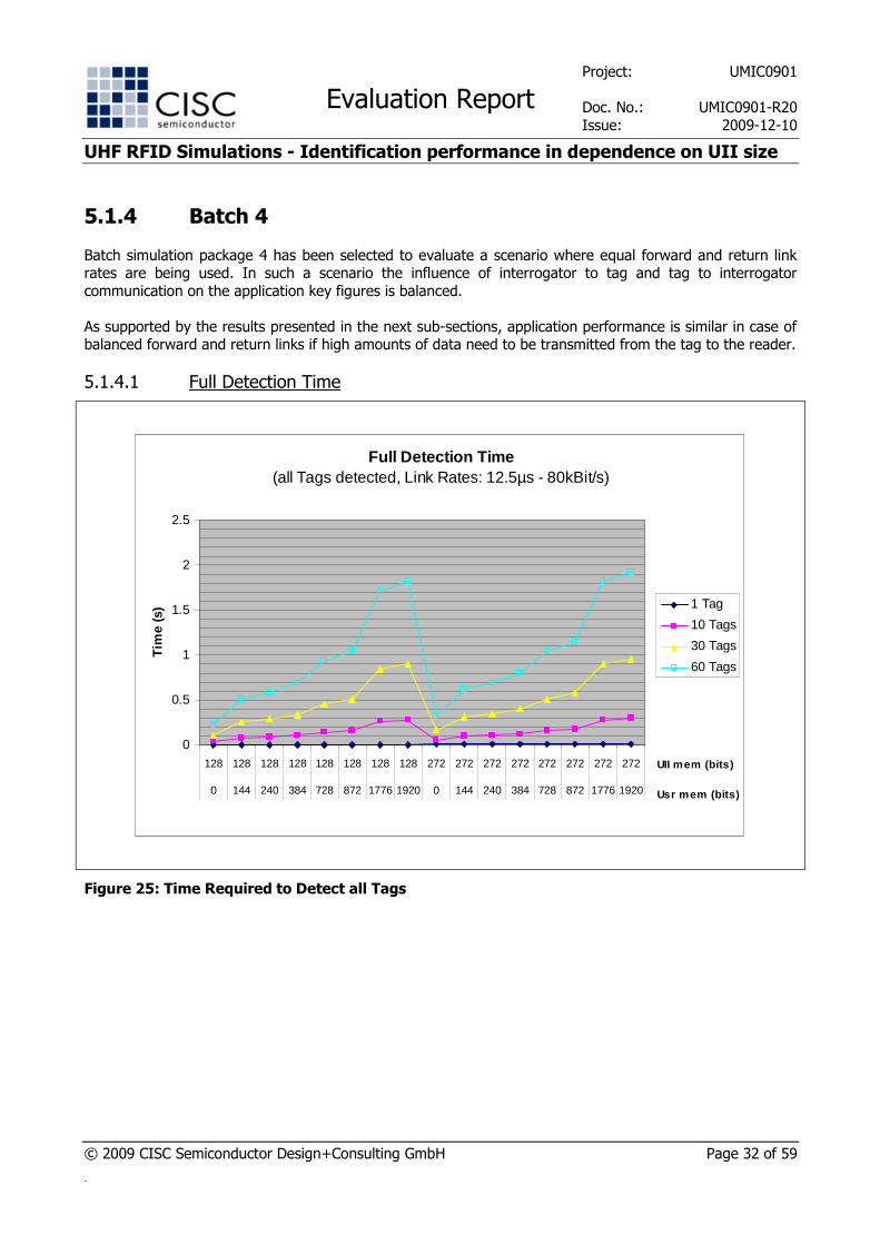
5.1.4 Batch 4
Batch simulation package 4 has been selected to evaluate a scenario where equal forward and return link rates are being used. In such a scenario the influence of interrogator to tag and tag to interrogator
communication on the application key figures is balanced.
As supported by the results presented in the next sub-sections, application performance is similar in case of balanced forward and return links if high amounts of data need to be transmitted from the tag to the reader.
5.1.4.1 Full Detection Time
Full Detection Time (all Tags detected, Link Rates: 12.5µs - 80kBit/s)
0
0.5
1
1.5
2
2.5
128 128 128 128 128 128 128 128 272 272 272 272 272 272 272 272
0 144 240 384 728 872 1776 1920 0 144 240 384 728 872 1776 1920
UII mem (bits)
Usr mem (bits)
Tim
e (s
) 1 Tag
10 Tags
30 Tags
60 Tags
Figure 25: Time Required to Detect all Tags
Project: UMIC0901
Evaluation Report Doc. No.: UMIC0901-R20
Issue: 2009-12-10
UHF RFID Simulations - Identification performance in dependence on UII size
© 2009 CISC Semiconductor Design+Consulting GmbH Page 33 of 59
.
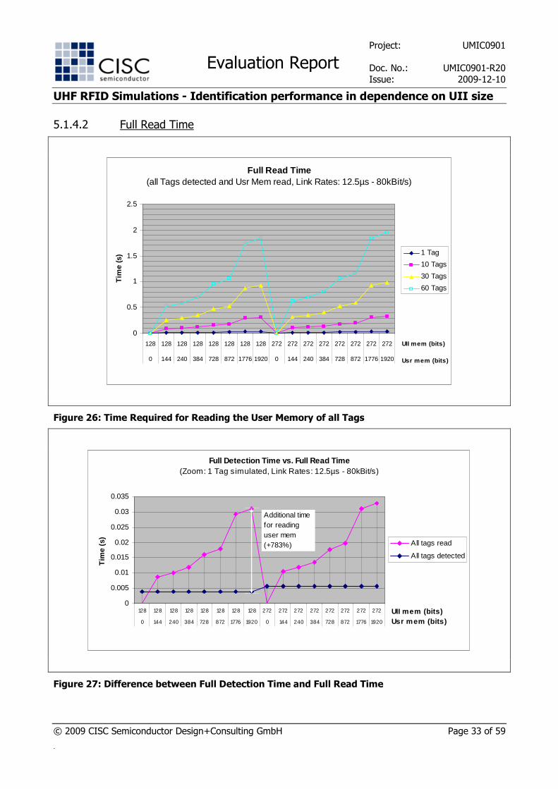
5.1.4.2 Full Read Time
Full Read Time (all Tags detected and Usr Mem read, Link Rates: 12.5µs - 80kBit/s)
0
0.5
1
1.5
2
2.5
128 128 128 128 128 128 128 128 272 272 272 272 272 272 272 272
0 144 240 384 728 872 1776 1920 0 144 240 384 728 872 1776 1920
UII mem (bits)
Usr mem (bits)
Tim
e (s
) 1 Tag
10 Tags
30 Tags
60 Tags
Figure 26: Time Required for Reading the User Memory of all Tags
Full Detection Time vs. Full Read Time(Zoom: 1 Tag simulated, Link Rates: 12.5µs - 80kBit/s)
0
0.005
0.01
0.015
0.02
0.025
0.03
0.035
128 128 128 128 128 128 128 128 272 272 272 272 272 272 272 272
0 144 240 384 728 872 1776 1920 0 144 240 384 728 872 1776 1920
UII mem (bits)Usr mem (bits)
Tim
e (s
)
All tags read
All tags detected
Additional time for reading user mem (+783%)
Figure 27: Difference between Full Detection Time and Full Read Time

Project: UMIC0901
Evaluation Report Doc. No.: UMIC0901-R20
Issue: 2009-12-10
UHF RFID Simulations - Identification performance in dependence on UII size
© 2009 CISC Semiconductor Design+Consulting GmbH Page 34 of 59
.
5.1.4.3 All Data Received
Fixed Amount of Total Data (1 Tag simulated, no anticollision, Link Rates: 12.5µs - 80kBit/s)
0
0.005
0.01
0.015
0.02
0.025
0.03
0.035
0 500 1000 1500 2000 2500
Total data (bits)
Tim
e un
til a
ll da
ta is
rec
eive
d (s
)
128-bit UII Memory
272-bit UII Memory
Special case: all data stored in UII Memory
Figure 28: Data Split between UII and User Memory
Project: UMIC0901
Evaluation Report Doc. No.: UMIC0901-R20
Issue: 2009-12-10
UHF RFID Simulations - Identification performance in dependence on UII size
© 2009 CISC Semiconductor Design+Consulting GmbH Page 35 of 59
.
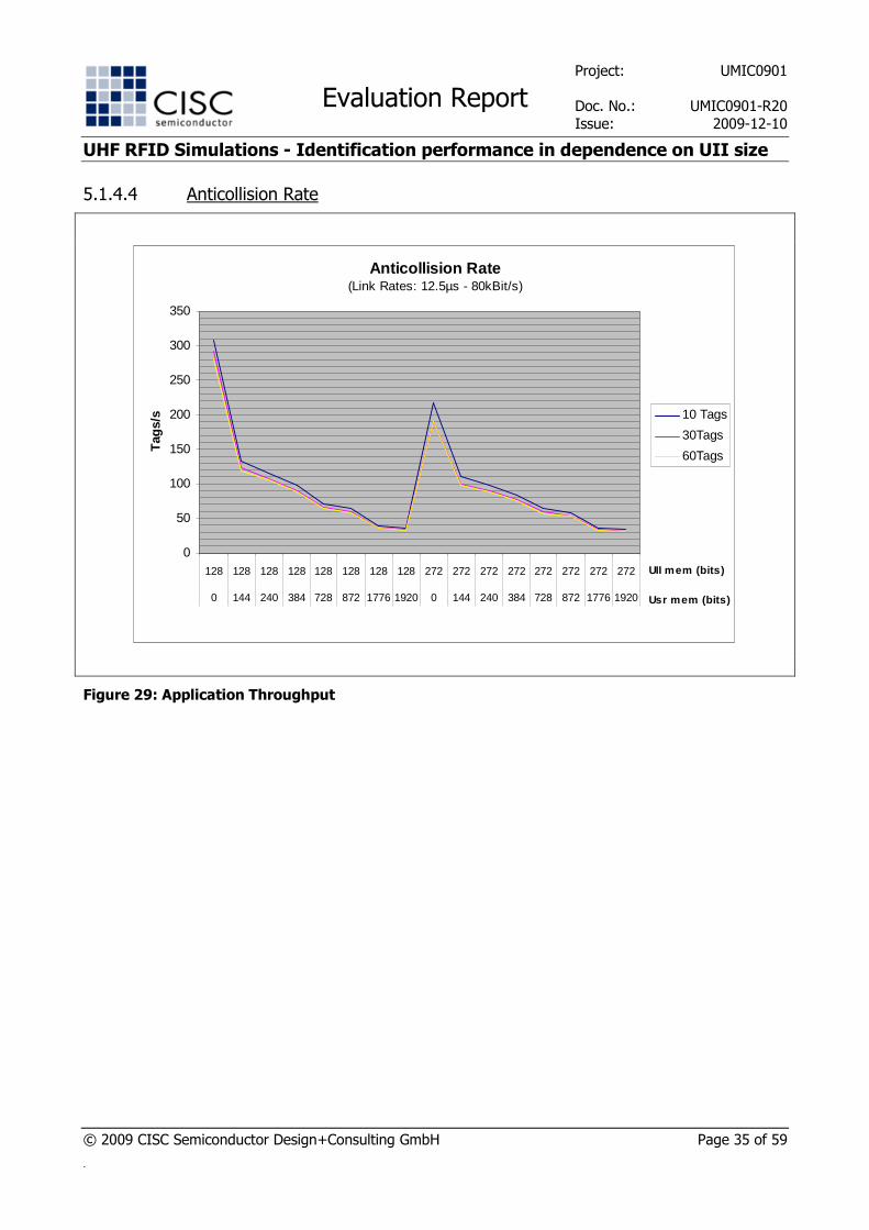
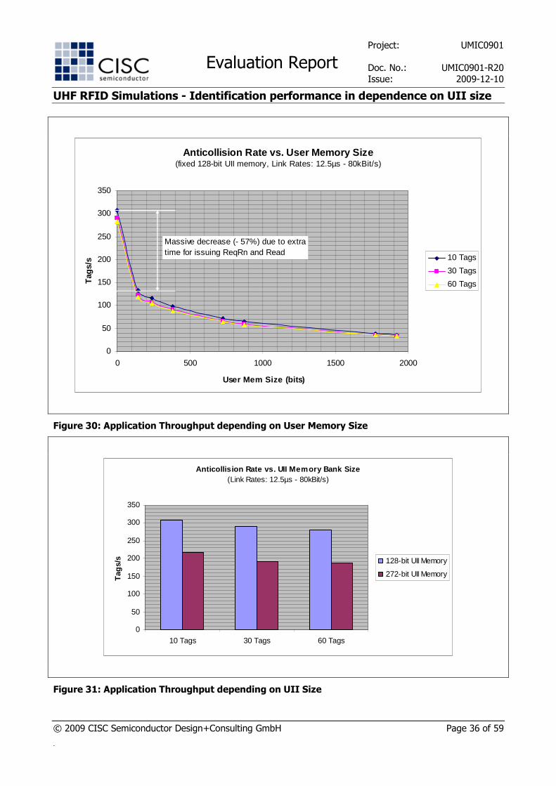
5.1.4.4 Anticollision Rate
Anticollision Rate(Link Rates: 12.5µs - 80kBit/s)
0
50
100
150
200
250
300
350
128 128 128 128 128 128 128 128 272 272 272 272 272 272 272 272
0 144 240 384 728 872 1776 1920 0 144 240 384 728 872 1776 1920
UII mem (bits)
Usr mem (bits)
Tag
s/s 10 Tags
30Tags
60Tags
Figure 29: Application Throughput
Project: UMIC0901
Evaluation Report Doc. No.: UMIC0901-R20
Issue: 2009-12-10
UHF RFID Simulations - Identification performance in dependence on UII size
© 2009 CISC Semiconductor Design+Consulting GmbH Page 36 of 59
.
Anticollision Rate vs. User Memory Size(fixed 128-bit UII memory, Link Rates: 12.5µs - 80kBit/s)
0
50
100
150
200
250
300
350
0 500 1000 1500 2000
User Mem Size (bits)
Tag
s/s 10 Tags
30 Tags
60 Tags
Massive decrease (- 57%) due to extra time for issuing ReqRn and Read
Figure 30: Application Throughput depending on User Memory Size
Anticollision Rate vs. UII Memory Bank Size(Link Rates: 12.5µs - 80kBit/s)
0
50
100
150
200
250
300
350
10 Tags 30 Tags 60 Tags
Tag
s/s 128-bit UII Memory
272-bit UII Memory
Figure 31: Application Throughput depending on UII Size
Project: UMIC0901
Evaluation Report Doc. No.: UMIC0901-R20
Issue: 2009-12-10
UHF RFID Simulations - Identification performance in dependence on UII size
© 2009 CISC Semiconductor Design+Consulting GmbH Page 37 of 59
.
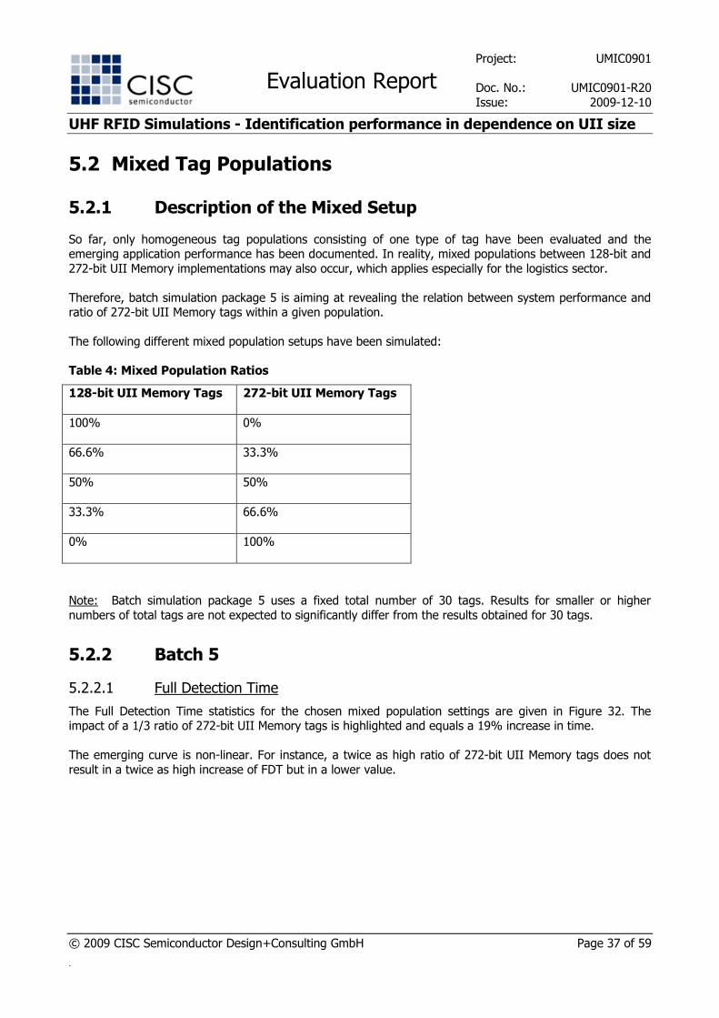
5.2 Mixed Tag Populations
5.2.1 Description of the Mixed Setup
So far, only homogeneous tag populations consisting of one type of tag have been evaluated and the emerging application performance has been documented. In reality, mixed populations between 128-bit and
272-bit UII Memory implementations may also occur, which applies especially for the logistics sector.
Therefore, batch simulation package 5 is aiming at revealing the relation between system performance and ratio of 272-bit UII Memory tags within a given population.
The following different mixed population setups have been simulated:
Table 4: Mixed Population Ratios
128-bit UII Memory Tags 272-bit UII Memory Tags
100% 0%
66.6% 33.3%
50% 50%
33.3% 66.6%
0% 100%
Note: Batch simulation package 5 uses a fixed total number of 30 tags. Results for smaller or higher
numbers of total tags are not expected to significantly differ from the results obtained for 30 tags.
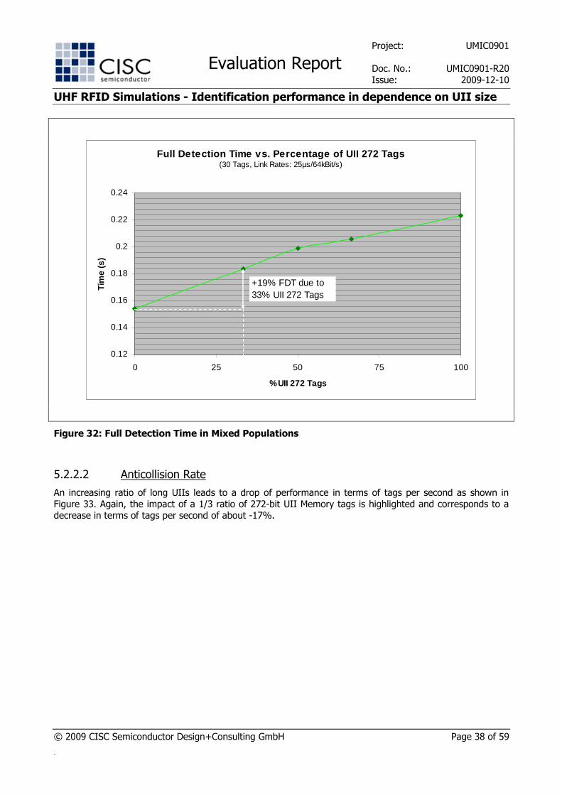
5.2.2 Batch 5
5.2.2.1 Full Detection Time
The Full Detection Time statistics for the chosen mixed population settings are given in Figure 32. The impact of a 1/3 ratio of 272-bit UII Memory tags is highlighted and equals a 19% increase in time.
The emerging curve is non-linear. For instance, a twice as high ratio of 272-bit UII Memory tags does not
result in a twice as high increase of FDT but in a lower value.
Project: UMIC0901
Evaluation Report Doc. No.: UMIC0901-R20
Issue: 2009-12-10
UHF RFID Simulations - Identification performance in dependence on UII size
© 2009 CISC Semiconductor Design+Consulting GmbH Page 38 of 59
.
Full Detection Time vs. Percentage of UII 272 Tags(30 Tags, Link Rates: 25µs/64kBit/s)
0.12
0.14
0.16
0.18
0.2
0.22
0.24
0 25 50 75 100
% UII 272 Tags
Tim
e (s
)
+19% FDT due to33% UII 272 Tags
Figure 32: Full Detection Time in Mixed Populations
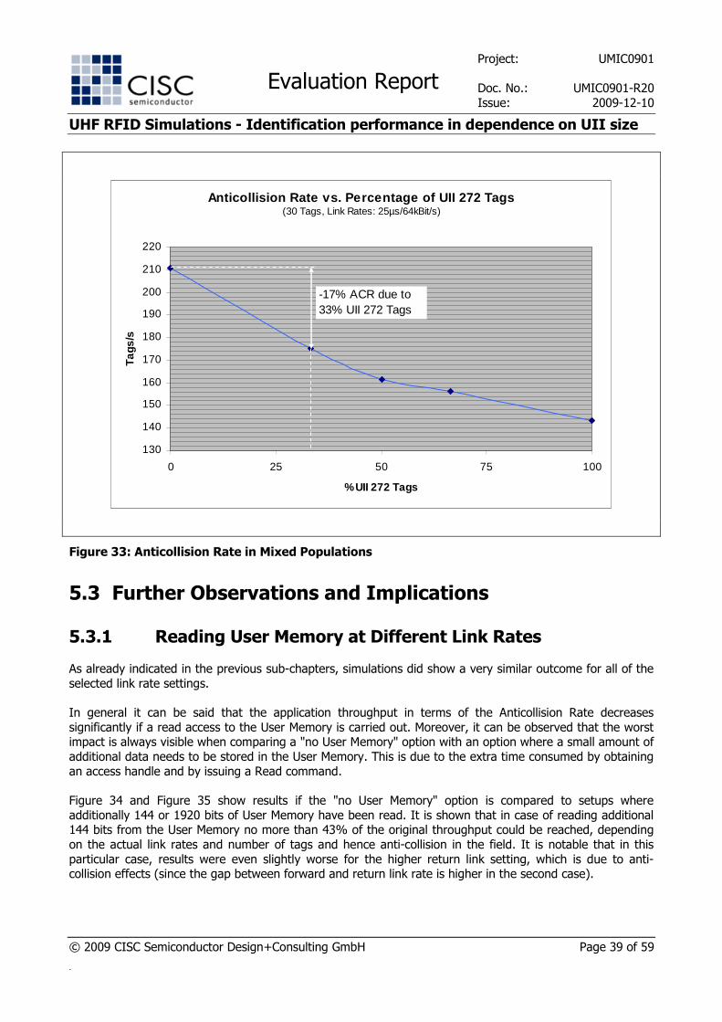
5.2.2.2 Anticollision Rate
An increasing ratio of long UIIs leads to a drop of performance in terms of tags per second as shown in
Figure 33. Again, the impact of a 1/3 ratio of 272-bit UII Memory tags is highlighted and corresponds to a decrease in terms of tags per second of about -17%.
Project: UMIC0901
Evaluation Report Doc. No.: UMIC0901-R20
Issue: 2009-12-10
UHF RFID Simulations - Identification performance in dependence on UII size
© 2009 CISC Semiconductor Design+Consulting GmbH Page 39 of 59
.
Anticollision Rate vs. Percentage of UII 272 Tags(30 Tags, Link Rates: 25µs/64kBit/s)
130
140
150
160
170
180
190
200
210
220
0 25 50 75 100
% UII 272 Tags
Tags
/s
-17% ACR due to33% UII 272 Tags
Figure 33: Anticollision Rate in Mixed Populations
5.3 Further Observations and Implications
5.3.1 Reading User Memory at Different Link Rates
As already indicated in the previous sub-chapters, simulations did show a very similar outcome for all of the
selected link rate settings.
In general it can be said that the application throughput in terms of the Anticollision Rate decreases
significantly if a read access to the User Memory is carried out. Moreover, it can be observed that the worst impact is always visible when comparing a "no User Memory" option with an option where a small amount of
additional data needs to be stored in the User Memory. This is due to the extra time consumed by obtaining
an access handle and by issuing a Read command.
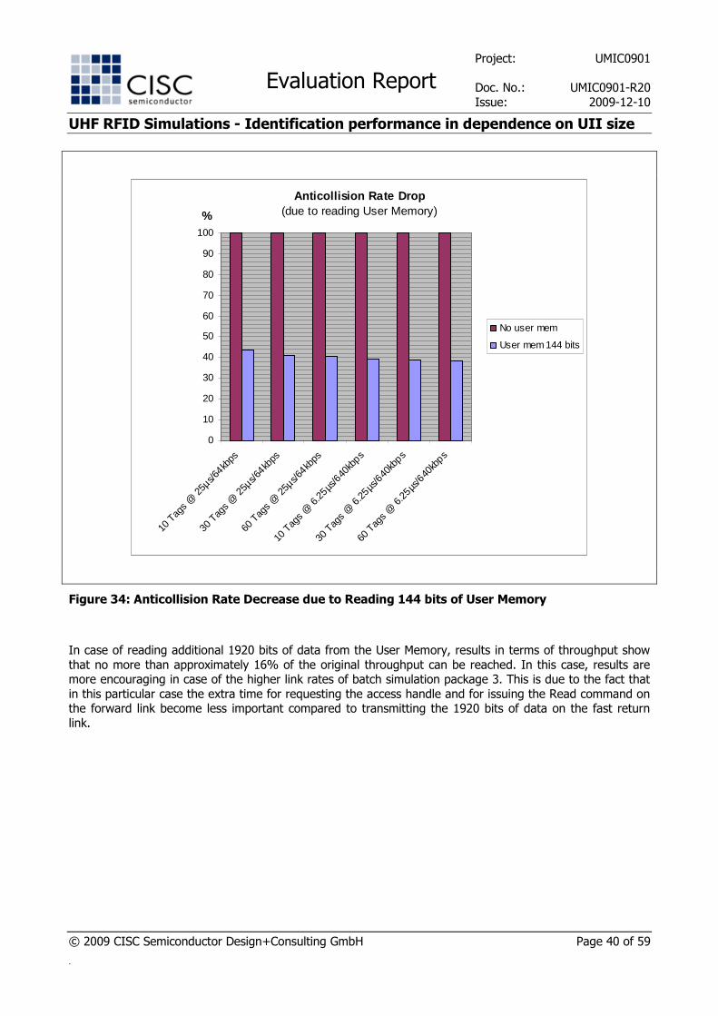
Figure 34 and Figure 35 show results if the "no User Memory" option is compared to setups where
additionally 144 or 1920 bits of User Memory have been read. It is shown that in case of reading additional 144 bits from the User Memory no more than 43% of the original throughput could be reached, depending
on the actual link rates and number of tags and hence anti-collision in the field. It is notable that in this
particular case, results were even slightly worse for the higher return link setting, which is due to anti-collision effects (since the gap between forward and return link rate is higher in the second case).
Project: UMIC0901
Evaluation Report Doc. No.: UMIC0901-R20
Issue: 2009-12-10
UHF RFID Simulations - Identification performance in dependence on UII size
© 2009 CISC Semiconductor Design+Consulting GmbH Page 40 of 59
.
Anticollision Rate Drop (due to reading User Memory)
0
10
20
30
40
50
60
70
80
90
100
10 T
ags @
25µ
s/64kb
ps
30 T
ags @
25µ
s/64kb
ps
60 T
ags @
25µ
s/64kb
ps
10 T
ags
@ 6
.25µs
/640
kbps
30 T
ags
@ 6
.25µs
/640
kbps
60 T
ags
@ 6
.25µs
/640
kbps
%
No user mem
User mem 144 bits
Figure 34: Anticollision Rate Decrease due to Reading 144 bits of User Memory
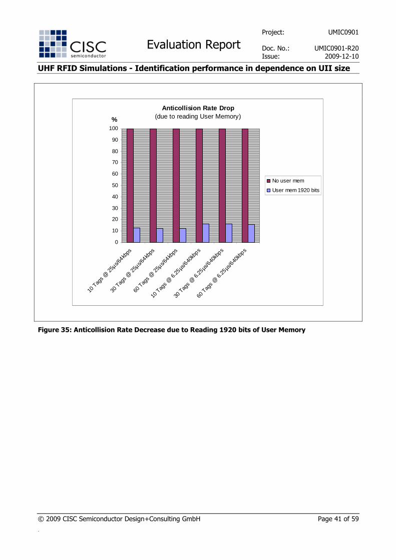
In case of reading additional 1920 bits of data from the User Memory, results in terms of throughput show
that no more than approximately 16% of the original throughput can be reached. In this case, results are more encouraging in case of the higher link rates of batch simulation package 3. This is due to the fact that
in this particular case the extra time for requesting the access handle and for issuing the Read command on the forward link become less important compared to transmitting the 1920 bits of data on the fast return
link.
Project: UMIC0901
Evaluation Report Doc. No.: UMIC0901-R20
Issue: 2009-12-10
UHF RFID Simulations - Identification performance in dependence on UII size
© 2009 CISC Semiconductor Design+Consulting GmbH Page 41 of 59
.
Anticollision Rate Drop (due to reading User Memory)
0
10
20
30
40
50
60
70
80
90
100
10 T
ags @
25µ
s/64kb
ps
30 T
ags @
25µ
s/64kb
ps
60 T
ags @
25µ
s/64kb
ps
10 T
ags
@ 6
.25µs
/640
kbps
30 T
ags
@ 6
.25µs
/640
kbps
60 T
ags
@ 6
.25µs
/640
kbps
%
No user mem
User mem 1920 bits
Figure 35: Anticollision Rate Decrease due to Reading 1920 bits of User Memory
Project: UMIC0901
Evaluation Report Doc. No.: UMIC0901-R20
Issue: 2009-12-10
UHF RFID Simulations - Identification performance in dependence on UII size
© 2009 CISC Semiconductor Design+Consulting GmbH Page 42 of 59
.
When comparing options where read access to the User Memory is required and only the amount of data
varies, the observed impact of reading some extra bytes is less significant.
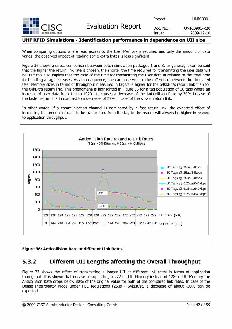
Figure 36 shows a direct comparison between batch simulation packages 1 and 3. In general, it can be said
that the higher the return link rate is chosen, the shorter the time required for transmitting the user data will be. But this also implies that the ratio of the time for transmitting the user data in relation to the total time
for handling a tag decreases. As a consequence, one can observe that the difference between the simulated
User Memory sizes in terms of throughput measured in tags/s is higher for the 640kBit/s return link than for the 64kBit/s return link. This phenomena is highlighted in Figure 36 for a tag population of 10 tags where an
increase of user data from 144 to 1920 bits causes a decrease of the Anticollision Rate by 70% in case of the faster return link in contrast to a decrease of 59% in case of the slower return link.
In other words, if a communication channel is dominated by a fast return link, the expected effect of
increasing the amount of data to be transmitted from the tag to the reader will always be higher in respect to application throughput.
Anticollision Rate related to Link Rates(25µs - 64kBit/s vs. 6.25µs - 640kBit/s)
0
200
400
600
800
1000
1200
1400
1600
128 128 128 128 128 128 128 128 272 272 272 272 272 272 272 272
0 144 240 384 728 872 17761920 0 144 240 384 728 872 17761920
UII mem (bits)
Usr mem (bits)
Tag
s/s
10 Tags @ 25µs/64kbps
30 Tags @ 25µs/64kbps
60 Tags @ 25µs/64kbps
10 Tags @ 6.25µs/640kbps
30 Tags @ 6.25µs/640kbps
60 Tags @ 6.25µs/640kbps
-59%
-70%
Figure 36: Anticollision Rate at different Link Rates
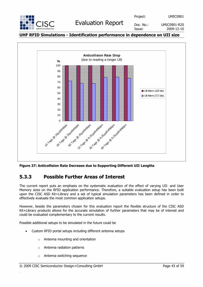
5.3.2 Different UII Lengths affecting the Overall Throughput
Figure 37 shows the effect of transmitting a longer UII at different link rates in terms of application throughput. It is shown that in case of supporting a 272-bit UII Memory instead of 128-bit UII Memory the
Anticollision Rate drops below 80% of the original value for both of the compared link rates. In case of the
Dense Interrogator Mode under FCC regulations (25µs - 64kBit/s), a decrease of about -30% can be expected.
Project: UMIC0901
Evaluation Report Doc. No.: UMIC0901-R20
Issue: 2009-12-10
UHF RFID Simulations - Identification performance in dependence on UII size
© 2009 CISC Semiconductor Design+Consulting GmbH Page 43 of 59
.
Anticollision Rate Drop (due to reading a longer UII)
0
10
20
30
40
50
60
70
80
90
100
10 T
ags @
25µ
s/64kb
ps
30 T
ags @
25µ
s/64kb
ps
60 T
ags @
25µ
s/64kb
ps
10 T
ags
@ 6
.25µs
/640
kbps
30 T
ags
@ 6
.25µs
/640
kbps
60 T
ags
@ 6
.25µs
/640
kbps
%
UII Mem 128 bits
UII Mem 272 bits
Figure 37: Anticollision Rate Decrease due to Supporting Different UII Lengths
5.3.3 Possible Further Areas of Interest
The current report puts an emphasis on the systematic evaluation of the effect of varying UII- and User Memory sizes on the RFID application performance. Therefore, a suitable evaluation setup has been built
upon the CISC ASD Kit+Library and a set of typical simulation parameters has been defined in order to effectively evaluate the most common application setups.
However, beside the parameters chosen for this evaluation report the flexible structure of the CISC ASD
Kit+Library products allows for the accurate simulation of further parameters that may be of interest and could be evaluated complementary to the current results.
Possible additional setups to be simulated in the future could be
• Custom RFID portal setups including different antenna setups
o Antenna mounting and orientation
o Antenna radiation patterns
o Antenna switching sequence

Project: UMIC0901
Evaluation Report Doc. No.: UMIC0901-R20
Issue: 2009-12-10
UHF RFID Simulations - Identification performance in dependence on UII size
© 2009 CISC Semiconductor Design+Consulting GmbH Page 44 of 59
.
• Custom pallet movement paths including varying movement speeds
• Interrogator to Tag and Tag to Interrogator bit error rates
• Random field null insertion
• Anticollision algorithm variations
• Different inventory sessions and persistency
• Mixed protocol tag populations
• …
Furthermore, environmental effects can be captured by means of the CISC RFID Field Recorder and
recorded location specific field data can be used as an input to simulations carried out with the CISC RFID ASD Kit+Library.
6 CONCLUSION
Based on the simulations carried out with CISC RFID ASD Kit+Library, a series of general implications can be
drawn for the use of UHF RFID tags according ISO/IEC 18000-6 Type C and User Memory use according ISO/IEC 15962.
First, it has to be outlined that application performance in terms of tags per second is directly dependent on the overall amount of data to be transmitted from the interrogator to the tag and vice versa. As a
consequence, transmission of a longer UII and additional read access to the tag's user memory correspond
to a significant decrease in performance. As a consequence, the proper use of the user-memory indicator (UMI, bit 15h of UII memory bank (MB01)) in the inventory algorithm implemented on the interrogator side
is important to avoid unnecessary read attempts to this optional memory bank that might not exist on each tag, which may lead to unnecessary communication steps. Especially for mixed populations, additionally to
the UMI bit, it is also recommended to check the NSI (bits 17h to 1Fh of MB01), which includes the AFI (bits
18h to 1Fh of MB01), any maybe even parts of the UII itself before deciding to the read the User Memory content.
Second, it has been shown that assuming a fixed amount of data that needs to be read there is no need to append part of this data to the UII for transmission in the response to the ACK command, if some more data
needs to be read from the User Memory in a separate step later on. However, if it is possible to keep the overall amount of application specific data very small, it can perfectly make sense to transmit it subsequent
to the UII.
Third, it has been shown that the occurrence of longer UII tags within a tag population slows down the application in terms of the Anticollision Rate depending on the actual ration of such tags.
Last but not least, it has to be considered that the higher the number of total tags in the field the higher the effort for singulating those tags by means of anti-collision will be, i.e. if the number of tags is not known in
advance by the interrogator and the q-parameter can not be set accordingly, and hence the time for reading
data from the tag plays a less dominant role in such cases.
Project: UMIC0901
Evaluation Report Doc. No.: UMIC0901-R20
Issue: 2009-12-10
UHF RFID Simulations - Identification performance in dependence on UII size
© 2009 CISC Semiconductor Design+Consulting GmbH Page 45 of 59
.
7 ANNEX: SIMULATION RESULTS
7.1 Overview
7.1.1 Batch 1
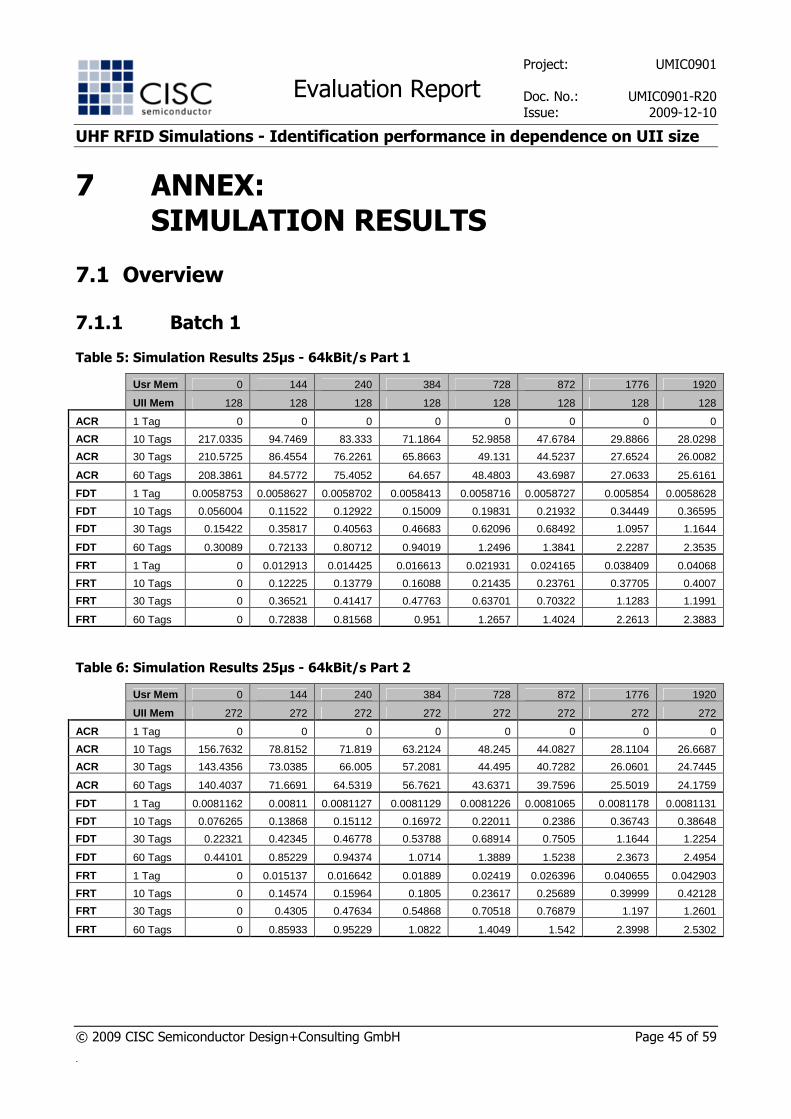
Table 5: Simulation Results 25µs - 64kBit/s Part 1
Usr Mem 0 144 240 384 728 872 1776 1920
UII Mem 128 128 128 128 128 128 128 128
ACR 1 Tag 0 0 0 0 0 0 0 0
ACR 10 Tags 217.0335 94.7469 83.333 71.1864 52.9858 47.6784 29.8866 28.0298
ACR 30 Tags 210.5725 86.4554 76.2261 65.8663 49.131 44.5237 27.6524 26.0082
ACR 60 Tags 208.3861 84.5772 75.4052 64.657 48.4803 43.6987 27.0633 25.6161
FDT 1 Tag 0.0058753 0.0058627 0.0058702 0.0058413 0.0058716 0.0058727 0.005854 0.0058628
FDT 10 Tags 0.056004 0.11522 0.12922 0.15009 0.19831 0.21932 0.34449 0.36595
FDT 30 Tags 0.15422 0.35817 0.40563 0.46683 0.62096 0.68492 1.0957 1.1644
FDT 60 Tags 0.30089 0.72133 0.80712 0.94019 1.2496 1.3841 2.2287 2.3535
FRT 1 Tag 0 0.012913 0.014425 0.016613 0.021931 0.024165 0.038409 0.04068
FRT 10 Tags 0 0.12225 0.13779 0.16088 0.21435 0.23761 0.37705 0.4007
FRT 30 Tags 0 0.36521 0.41417 0.47763 0.63701 0.70322 1.1283 1.1991
FRT 60 Tags 0 0.72838 0.81568 0.951 1.2657 1.4024 2.2613 2.3883
Table 6: Simulation Results 25µs - 64kBit/s Part 2
Usr Mem 0 144 240 384 728 872 1776 1920
UII Mem 272 272 272 272 272 272 272 272
ACR 1 Tag 0 0 0 0 0 0 0 0
ACR 10 Tags 156.7632 78.8152 71.819 63.2124 48.245 44.0827 28.1104 26.6687
ACR 30 Tags 143.4356 73.0385 66.005 57.2081 44.495 40.7282 26.0601 24.7445
ACR 60 Tags 140.4037 71.6691 64.5319 56.7621 43.6371 39.7596 25.5019 24.1759
FDT 1 Tag 0.0081162 0.00811 0.0081127 0.0081129 0.0081226 0.0081065 0.0081178 0.0081131
FDT 10 Tags 0.076265 0.13868 0.15112 0.16972 0.22011 0.2386 0.36743 0.38648
FDT 30 Tags 0.22321 0.42345 0.46778 0.53788 0.68914 0.7505 1.1644 1.2254
FDT 60 Tags 0.44101 0.85229 0.94374 1.0714 1.3889 1.5238 2.3673 2.4954
FRT 1 Tag 0 0.015137 0.016642 0.01889 0.02419 0.026396 0.040655 0.042903
FRT 10 Tags 0 0.14574 0.15964 0.1805 0.23617 0.25689 0.39999 0.42128
FRT 30 Tags 0 0.4305 0.47634 0.54868 0.70518 0.76879 1.197 1.2601
FRT 60 Tags 0 0.85933 0.95229 1.0822 1.4049 1.542 2.3998 2.5302
Project: UMIC0901
Evaluation Report Doc. No.: UMIC0901-R20
Issue: 2009-12-10
UHF RFID Simulations - Identification performance in dependence on UII size
© 2009 CISC Semiconductor Design+Consulting GmbH Page 46 of 59
.
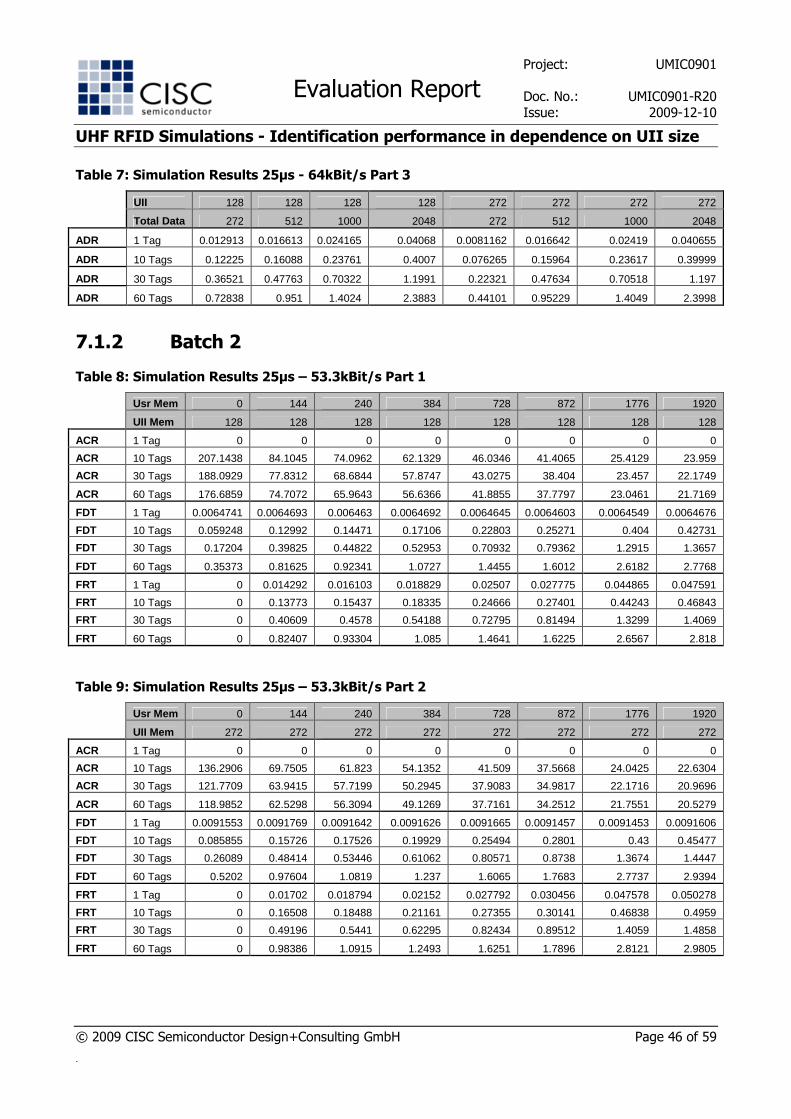
Table 7: Simulation Results 25µs - 64kBit/s Part 3
UII 128 128 128 128 272 272 272 272
Total Data 272 512 1000 2048 272 512 1000 2048
ADR 1 Tag 0.012913 0.016613 0.024165 0.04068 0.0081162 0.016642 0.02419 0.040655
ADR 10 Tags 0.12225 0.16088 0.23761 0.4007 0.076265 0.15964 0.23617 0.39999
ADR 30 Tags 0.36521 0.47763 0.70322 1.1991 0.22321 0.47634 0.70518 1.197
ADR 60 Tags 0.72838 0.951 1.4024 2.3883 0.44101 0.95229 1.4049 2.3998
7.1.2 Batch 2
Table 8: Simulation Results 25µs – 53.3kBit/s Part 1
Usr Mem 0 144 240 384 728 872 1776 1920
UII Mem 128 128 128 128 128 128 128 128
ACR 1 Tag 0 0 0 0 0 0 0 0
ACR 10 Tags 207.1438 84.1045 74.0962 62.1329 46.0346 41.4065 25.4129 23.959
ACR 30 Tags 188.0929 77.8312 68.6844 57.8747 43.0275 38.404 23.457 22.1749
ACR 60 Tags 176.6859 74.7072 65.9643 56.6366 41.8855 37.7797 23.0461 21.7169
FDT 1 Tag 0.0064741 0.0064693 0.006463 0.0064692 0.0064645 0.0064603 0.0064549 0.0064676
FDT 10 Tags 0.059248 0.12992 0.14471 0.17106 0.22803 0.25271 0.404 0.42731
FDT 30 Tags 0.17204 0.39825 0.44822 0.52953 0.70932 0.79362 1.2915 1.3657
FDT 60 Tags 0.35373 0.81625 0.92341 1.0727 1.4455 1.6012 2.6182 2.7768
FRT 1 Tag 0 0.014292 0.016103 0.018829 0.02507 0.027775 0.044865 0.047591
FRT 10 Tags 0 0.13773 0.15437 0.18335 0.24666 0.27401 0.44243 0.46843
FRT 30 Tags 0 0.40609 0.4578 0.54188 0.72795 0.81494 1.3299 1.4069
FRT 60 Tags 0 0.82407 0.93304 1.085 1.4641 1.6225 2.6567 2.818
Table 9: Simulation Results 25µs – 53.3kBit/s Part 2
Usr Mem 0 144 240 384 728 872 1776 1920
UII Mem 272 272 272 272 272 272 272 272
ACR 1 Tag 0 0 0 0 0 0 0 0
ACR 10 Tags 136.2906 69.7505 61.823 54.1352 41.509 37.5668 24.0425 22.6304
ACR 30 Tags 121.7709 63.9415 57.7199 50.2945 37.9083 34.9817 22.1716 20.9696
ACR 60 Tags 118.9852 62.5298 56.3094 49.1269 37.7161 34.2512 21.7551 20.5279
FDT 1 Tag 0.0091553 0.0091769 0.0091642 0.0091626 0.0091665 0.0091457 0.0091453 0.0091606
FDT 10 Tags 0.085855 0.15726 0.17526 0.19929 0.25494 0.2801 0.43 0.45477
FDT 30 Tags 0.26089 0.48414 0.53446 0.61062 0.80571 0.8738 1.3674 1.4447
FDT 60 Tags 0.5202 0.97604 1.0819 1.237 1.6065 1.7683 2.7737 2.9394
FRT 1 Tag 0 0.01702 0.018794 0.02152 0.027792 0.030456 0.047578 0.050278
FRT 10 Tags 0 0.16508 0.18488 0.21161 0.27355 0.30141 0.46838 0.4959
FRT 30 Tags 0 0.49196 0.5441 0.62295 0.82434 0.89512 1.4059 1.4858
FRT 60 Tags 0 0.98386 1.0915 1.2493 1.6251 1.7896 2.8121 2.9805
Project: UMIC0901
Evaluation Report Doc. No.: UMIC0901-R20
Issue: 2009-12-10
UHF RFID Simulations - Identification performance in dependence on UII size
© 2009 CISC Semiconductor Design+Consulting GmbH Page 47 of 59
.
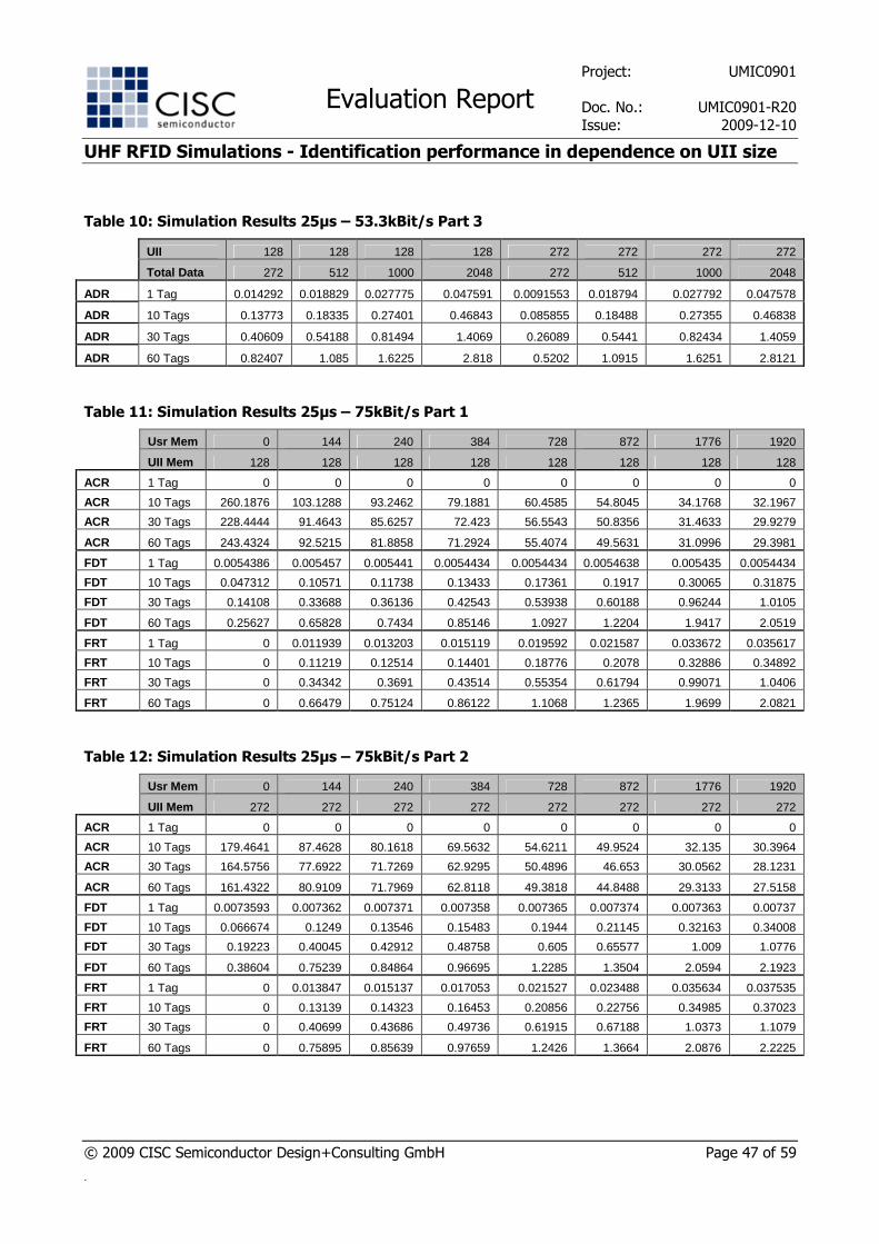
Table 10: Simulation Results 25µs – 53.3kBit/s Part 3
UII 128 128 128 128 272 272 272 272
Total Data 272 512 1000 2048 272 512 1000 2048
ADR 1 Tag 0.014292 0.018829 0.027775 0.047591 0.0091553 0.018794 0.027792 0.047578
ADR 10 Tags 0.13773 0.18335 0.27401 0.46843 0.085855 0.18488 0.27355 0.46838
ADR 30 Tags 0.40609 0.54188 0.81494 1.4069 0.26089 0.5441 0.82434 1.4059
ADR 60 Tags 0.82407 1.085 1.6225 2.818 0.5202 1.0915 1.6251 2.8121
Table 11: Simulation Results 25µs – 75kBit/s Part 1
Usr Mem 0 144 240 384 728 872 1776 1920
UII Mem 128 128 128 128 128 128 128 128
ACR 1 Tag 0 0 0 0 0 0 0 0
ACR 10 Tags 260.1876 103.1288 93.2462 79.1881 60.4585 54.8045 34.1768 32.1967
ACR 30 Tags 228.4444 91.4643 85.6257 72.423 56.5543 50.8356 31.4633 29.9279
ACR 60 Tags 243.4324 92.5215 81.8858 71.2924 55.4074 49.5631 31.0996 29.3981
FDT 1 Tag 0.0054386 0.005457 0.005441 0.0054434 0.0054434 0.0054638 0.005435 0.0054434
FDT 10 Tags 0.047312 0.10571 0.11738 0.13433 0.17361 0.1917 0.30065 0.31875
FDT 30 Tags 0.14108 0.33688 0.36136 0.42543 0.53938 0.60188 0.96244 1.0105
FDT 60 Tags 0.25627 0.65828 0.7434 0.85146 1.0927 1.2204 1.9417 2.0519
FRT 1 Tag 0 0.011939 0.013203 0.015119 0.019592 0.021587 0.033672 0.035617
FRT 10 Tags 0 0.11219 0.12514 0.14401 0.18776 0.2078 0.32886 0.34892
FRT 30 Tags 0 0.34342 0.3691 0.43514 0.55354 0.61794 0.99071 1.0406
FRT 60 Tags 0 0.66479 0.75124 0.86122 1.1068 1.2365 1.9699 2.0821
Table 12: Simulation Results 25µs – 75kBit/s Part 2
Usr Mem 0 144 240 384 728 872 1776 1920
UII Mem 272 272 272 272 272 272 272 272
ACR 1 Tag 0 0 0 0 0 0 0 0
ACR 10 Tags 179.4641 87.4628 80.1618 69.5632 54.6211 49.9524 32.135 30.3964
ACR 30 Tags 164.5756 77.6922 71.7269 62.9295 50.4896 46.653 30.0562 28.1231
ACR 60 Tags 161.4322 80.9109 71.7969 62.8118 49.3818 44.8488 29.3133 27.5158
FDT 1 Tag 0.0073593 0.007362 0.007371 0.007358 0.007365 0.007374 0.007363 0.00737
FDT 10 Tags 0.066674 0.1249 0.13546 0.15483 0.1944 0.21145 0.32163 0.34008
FDT 30 Tags 0.19223 0.40045 0.42912 0.48758 0.605 0.65577 1.009 1.0776
FDT 60 Tags 0.38604 0.75239 0.84864 0.96695 1.2285 1.3504 2.0594 2.1923
FRT 1 Tag 0 0.013847 0.015137 0.017053 0.021527 0.023488 0.035634 0.037535
FRT 10 Tags 0 0.13139 0.14323 0.16453 0.20856 0.22756 0.34985 0.37023
FRT 30 Tags 0 0.40699 0.43686 0.49736 0.61915 0.67188 1.0373 1.1079
FRT 60 Tags 0 0.75895 0.85639 0.97659 1.2426 1.3664 2.0876 2.2225
Project: UMIC0901
Evaluation Report Doc. No.: UMIC0901-R20
Issue: 2009-12-10
UHF RFID Simulations - Identification performance in dependence on UII size
© 2009 CISC Semiconductor Design+Consulting GmbH Page 48 of 59
.
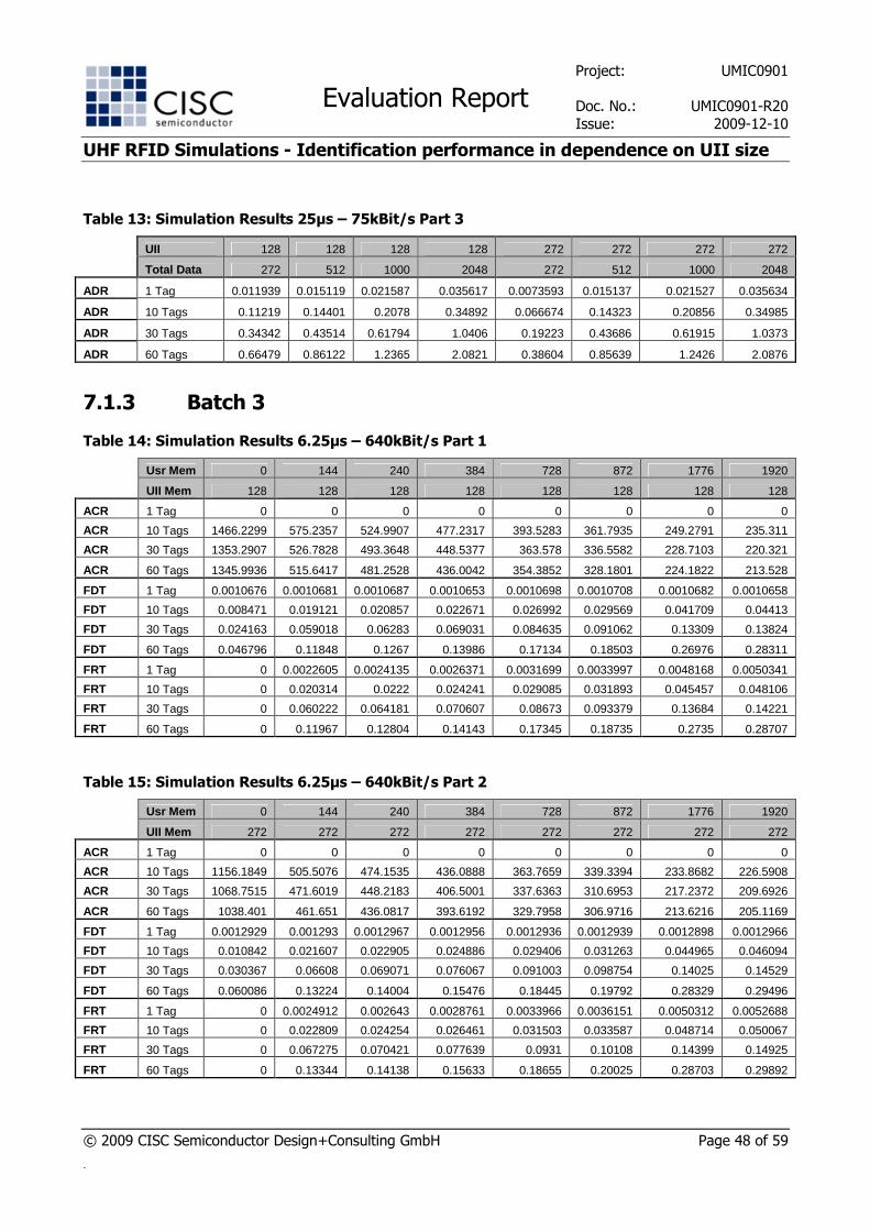
Table 13: Simulation Results 25µs – 75kBit/s Part 3
UII 128 128 128 128 272 272 272 272
Total Data 272 512 1000 2048 272 512 1000 2048
ADR 1 Tag 0.011939 0.015119 0.021587 0.035617 0.0073593 0.015137 0.021527 0.035634
ADR 10 Tags 0.11219 0.14401 0.2078 0.34892 0.066674 0.14323 0.20856 0.34985
ADR 30 Tags 0.34342 0.43514 0.61794 1.0406 0.19223 0.43686 0.61915 1.0373
ADR 60 Tags 0.66479 0.86122 1.2365 2.0821 0.38604 0.85639 1.2426 2.0876
7.1.3 Batch 3
Table 14: Simulation Results 6.25µs – 640kBit/s Part 1
Usr Mem 0 144 240 384 728 872 1776 1920
UII Mem 128 128 128 128 128 128 128 128
ACR 1 Tag 0 0 0 0 0 0 0 0
ACR 10 Tags 1466.2299 575.2357 524.9907 477.2317 393.5283 361.7935 249.2791 235.311
ACR 30 Tags 1353.2907 526.7828 493.3648 448.5377 363.578 336.5582 228.7103 220.321
ACR 60 Tags 1345.9936 515.6417 481.2528 436.0042 354.3852 328.1801 224.1822 213.528
FDT 1 Tag 0.0010676 0.0010681 0.0010687 0.0010653 0.0010698 0.0010708 0.0010682 0.0010658
FDT 10 Tags 0.008471 0.019121 0.020857 0.022671 0.026992 0.029569 0.041709 0.04413
FDT 30 Tags 0.024163 0.059018 0.06283 0.069031 0.084635 0.091062 0.13309 0.13824
FDT 60 Tags 0.046796 0.11848 0.1267 0.13986 0.17134 0.18503 0.26976 0.28311
FRT 1 Tag 0 0.0022605 0.0024135 0.0026371 0.0031699 0.0033997 0.0048168 0.0050341
FRT 10 Tags 0 0.020314 0.0222 0.024241 0.029085 0.031893 0.045457 0.048106
FRT 30 Tags 0 0.060222 0.064181 0.070607 0.08673 0.093379 0.13684 0.14221
FRT 60 Tags 0 0.11967 0.12804 0.14143 0.17345 0.18735 0.2735 0.28707
Table 15: Simulation Results 6.25µs – 640kBit/s Part 2
Usr Mem 0 144 240 384 728 872 1776 1920
UII Mem 272 272 272 272 272 272 272 272
ACR 1 Tag 0 0 0 0 0 0 0 0
ACR 10 Tags 1156.1849 505.5076 474.1535 436.0888 363.7659 339.3394 233.8682 226.5908
ACR 30 Tags 1068.7515 471.6019 448.2183 406.5001 337.6363 310.6953 217.2372 209.6926
ACR 60 Tags 1038.401 461.651 436.0817 393.6192 329.7958 306.9716 213.6216 205.1169
FDT 1 Tag 0.0012929 0.001293 0.0012967 0.0012956 0.0012936 0.0012939 0.0012898 0.0012966
FDT 10 Tags 0.010842 0.021607 0.022905 0.024886 0.029406 0.031263 0.044965 0.046094
FDT 30 Tags 0.030367 0.06608 0.069071 0.076067 0.091003 0.098754 0.14025 0.14529
FDT 60 Tags 0.060086 0.13224 0.14004 0.15476 0.18445 0.19792 0.28329 0.29496
FRT 1 Tag 0 0.0024912 0.002643 0.0028761 0.0033966 0.0036151 0.0050312 0.0052688
FRT 10 Tags 0 0.022809 0.024254 0.026461 0.031503 0.033587 0.048714 0.050067
FRT 30 Tags 0 0.067275 0.070421 0.077639 0.0931 0.10108 0.14399 0.14925
FRT 60 Tags 0 0.13344 0.14138 0.15633 0.18655 0.20025 0.28703 0.29892
Project: UMIC0901
Evaluation Report Doc. No.: UMIC0901-R20
Issue: 2009-12-10
UHF RFID Simulations - Identification performance in dependence on UII size
© 2009 CISC Semiconductor Design+Consulting GmbH Page 49 of 59
.
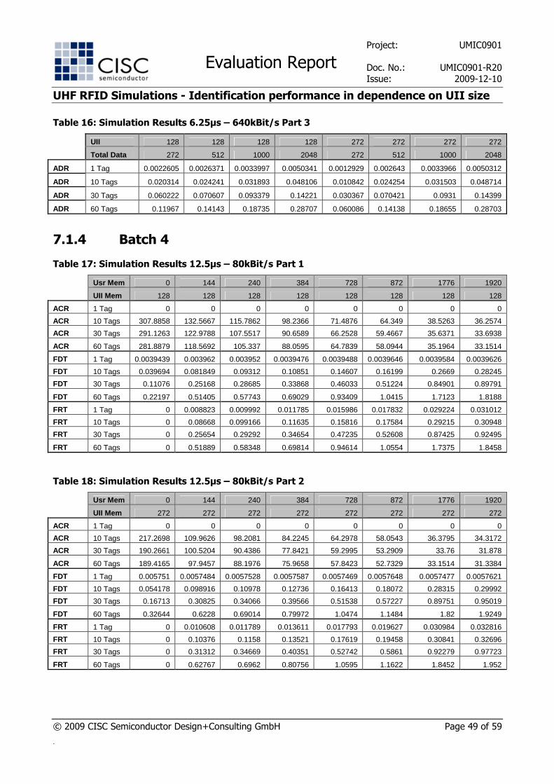
Table 16: Simulation Results 6.25µs – 640kBit/s Part 3
UII 128 128 128 128 272 272 272 272
Total Data 272 512 1000 2048 272 512 1000 2048
ADR 1 Tag 0.0022605 0.0026371 0.0033997 0.0050341 0.0012929 0.002643 0.0033966 0.0050312
ADR 10 Tags 0.020314 0.024241 0.031893 0.048106 0.010842 0.024254 0.031503 0.048714
ADR 30 Tags 0.060222 0.070607 0.093379 0.14221 0.030367 0.070421 0.0931 0.14399
ADR 60 Tags 0.11967 0.14143 0.18735 0.28707 0.060086 0.14138 0.18655 0.28703
7.1.4 Batch 4
Table 17: Simulation Results 12.5µs – 80kBit/s Part 1
Usr Mem 0 144 240 384 728 872 1776 1920
UII Mem 128 128 128 128 128 128 128 128
ACR 1 Tag 0 0 0 0 0 0 0 0
ACR 10 Tags 307.8858 132.5667 115.7862 98.2366 71.4876 64.349 38.5263 36.2574
ACR 30 Tags 291.1263 122.9788 107.5517 90.6589 66.2528 59.4667 35.6371 33.6938
ACR 60 Tags 281.8879 118.5692 105.337 88.0595 64.7839 58.0944 35.1964 33.1514
FDT 1 Tag 0.0039439 0.003962 0.003952 0.0039476 0.0039488 0.0039646 0.0039584 0.0039626
FDT 10 Tags 0.039694 0.081849 0.09312 0.10851 0.14607 0.16199 0.2669 0.28245
FDT 30 Tags 0.11076 0.25168 0.28685 0.33868 0.46033 0.51224 0.84901 0.89791
FDT 60 Tags 0.22197 0.51405 0.57743 0.69029 0.93409 1.0415 1.7123 1.8188
FRT 1 Tag 0 0.008823 0.009992 0.011785 0.015986 0.017832 0.029224 0.031012
FRT 10 Tags 0 0.08668 0.099166 0.11635 0.15816 0.17584 0.29215 0.30948
FRT 30 Tags 0 0.25654 0.29292 0.34654 0.47235 0.52608 0.87425 0.92495
FRT 60 Tags 0 0.51889 0.58348 0.69814 0.94614 1.0554 1.7375 1.8458
Table 18: Simulation Results 12.5µs – 80kBit/s Part 2
Usr Mem 0 144 240 384 728 872 1776 1920
UII Mem 272 272 272 272 272 272 272 272
ACR 1 Tag 0 0 0 0 0 0 0 0
ACR 10 Tags 217.2698 109.9626 98.2081 84.2245 64.2978 58.0543 36.3795 34.3172
ACR 30 Tags 190.2661 100.5204 90.4386 77.8421 59.2995 53.2909 33.76 31.878
ACR 60 Tags 189.4165 97.9457 88.1976 75.9658 57.8423 52.7329 33.1514 31.3384
FDT 1 Tag 0.005751 0.0057484 0.0057528 0.0057587 0.0057469 0.0057648 0.0057477 0.0057621
FDT 10 Tags 0.054178 0.098916 0.10978 0.12736 0.16413 0.18072 0.28315 0.29992
FDT 30 Tags 0.16713 0.30825 0.34066 0.39566 0.51538 0.57227 0.89751 0.95019
FDT 60 Tags 0.32644 0.6228 0.69014 0.79972 1.0474 1.1484 1.82 1.9249
FRT 1 Tag 0 0.010608 0.011789 0.013611 0.017793 0.019627 0.030984 0.032816
FRT 10 Tags 0 0.10376 0.1158 0.13521 0.17619 0.19458 0.30841 0.32696
FRT 30 Tags 0 0.31312 0.34669 0.40351 0.52742 0.5861 0.92279 0.97723
FRT 60 Tags 0 0.62767 0.6962 0.80756 1.0595 1.1622 1.8452 1.952
Project: UMIC0901
Evaluation Report Doc. No.: UMIC0901-R20
Issue: 2009-12-10
UHF RFID Simulations - Identification performance in dependence on UII size
© 2009 CISC Semiconductor Design+Consulting GmbH Page 50 of 59
.
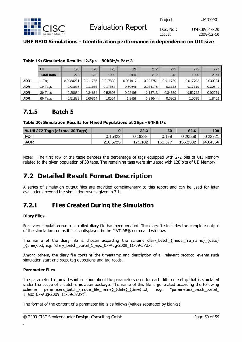
Table 19: Simulation Results 12.5µs – 80kBit/s Part 3
UII 128 128 128 128 272 272 272 272
Total Data 272 512 1000 2048 272 512 1000 2048
ADR 1 Tag 0.0088231 0.011785 0.017832 0.031012 0.005751 0.011789 0.017793 0.030984
ADR 10 Tags 0.08668 0.11635 0.17584 0.30948 0.054178 0.1158 0.17619 0.30841
ADR 30 Tags 0.25654 0.34654 0.52608 0.92495 0.16713 0.34669 0.52742 0.92279
ADR 60 Tags 0.51889 0.69814 1.0554 1.8458 0.32644 0.6962 1.0595 1.8452
7.1.5 Batch 5
Table 20: Simulation Results for Mixed Populations at 25µs - 64kBit/s
% UII 272 Tags (of total 30 Tags) 0 33.3 50 66.6 100 FDT 0.15422 0.18384 0.199 0.20558 0.22321 ACR 210.5725 175.182 161.577 156.2332 143.4356
Note: The first row of the table denotes the percentage of tags equipped with 272 bits of UII Memory related to the given population of 30 tags. The remaining tags were simulated with 128 bits of UII Memory.
7.2 Detailed Result Format Description
A series of simulation output files are provided complimentary to this report and can be used for later evaluations beyond the simulation results given in 7.1.
7.2.1 Files Created During the Simulation
Diary Files
For every simulation run a so called diary file has been created. The diary file includes the complete output
of the simulation run as it is also displayed in the MATLAB® command window.
The name of the diary file is chosen according the scheme diary_batch_{model_file_name}_{date}
_{time}.txt, e.g. “diary_batch_portal_1_epc_07-Aug-2009_11-09-37.txt".
Among others, the diary file contains the timestamp and description of all relevant protocol events such
simulation start and stop, tag detections and tag reads.
Parameter Files
The parameter file provides information about the parameters used for each different setup that is simulated
under the scope of a batch simulation package. The name of this file is generated according the following scheme parameters_batch_{model_file_name}_{date}_{time}.txt, e.g. “parameters_batch_portal_
1_epc_07-Aug-2009_11-09-37.txt”.
The format of the content of a parameter file is as follows (values separated by blanks):
Project: UMIC0901
Evaluation Report Doc. No.: UMIC0901-R20
Issue: 2009-12-10
UHF RFID Simulations - Identification performance in dependence on UII size
© 2009 CISC Semiconductor Design+Consulting GmbH Page 51 of 59
.
SimGroup FirstSim LastSim NrTags ParametersString
where "ParametersString" contains short description of the parameters used in the current simulation group
"SimGroup". Each simulation group consists of 10 single simulations from "FirstSim" up to "LastSim", which
are later cumulated for the purpose of result evaluation.
The link rates information included in the parameter string is encoded as follows:
• 3 = 12.5µs - 80kBit/s
• 6 = 6.25µs - 640kBit/s
• 7 = 25µs - 53.3kBit/s
• 8 = 25µs - 64kBit/s
• A = 25µs - 75kBit/s
The UII- and User Memory sizes are always given in bits and refer to the contents of the whole memory banks.
7.2.2 Files Created After the Simulation for the Purpose of Evaluation
Parsed Diary Files
For each batch simulation package a derivate of the original diary file is available. The name of this file is
parsed_{diaryfile}.txt, e.g. “parsed_diary_batch_portal_1_epc_07-Aug-2009_11-09-37.txt”.
This file contains the parsed tag detections in the following format (values separated by blanks):
SimNr Antenna TimeOfDetection TotalDetections DifferentDetections
where "Antenna" is always 1 (since no antenna switching is simulated) and "TimeOfDetection" is the exact
time of the tag detection in seconds measured from the begin of the simulation until the occurrence of the
event.
Tag Detections Evaluation File
The tag detections evaluation file is named eval_{diaryfile}.txt, e.g. “eval_diary_batch_portal_1_epc_07-Aug-2009_11-09-37.txt”, and is created as an auxiliary evaluation file during result evaluation.
It contains the following evaluation data (values separated by blanks):
SimNr FirstTag LastTag FullDetectionTime AnticollisionTime ↓ TotalDetections DifferentDetections AnticollisionRate
Tag Detections Result File
Project: UMIC0901
Evaluation Report Doc. No.: UMIC0901-R20
Issue: 2009-12-10
UHF RFID Simulations - Identification performance in dependence on UII size
© 2009 CISC Semiconductor Design+Consulting GmbH Page 52 of 59
.
The tag detections result file contains the performance key figures calculated in respect to tag detections for
the current batch simulation package and is named according the scheme result_{diaryfile}.txt, e.g. “result_diary_batch_portal_1_epc_07-Aug-2009_11-09-37.txt”.
The tag detections result file contains the following data for each simulation package:
SimGroup FirstTag NrValues LastTag NrValues FullDetectionTime NrValues AnticollisionTime NrValues TotalDetections NrValues DifferentDetections NrValues AnticollisionRate NrValues
where "NrValues" always denotes the number of single simulation runs that have been taken into account for the previous averaged value. For the given simulation setup this will always be 10 since the RF field is
always on and all tags are detected in each single simulation run.
Tag Reads Evaluation File
The tag reads evaluation file is an auxiliary file used for evaluation of the tag read events and is named
according the scheme eval_readUsrAll_{diaryfile}.txt, e.g. “eval_readUsrAll_diary_batch_portal_1_epc_07-Aug-2009_11-09-37.txt”
It contains data according the following structure (values separated by blanks):
SimNr AllTagsReadTimeStamp
where "AllTagsReadTimeStamp" is the exact point of time where all tags in the simulation have been detected and their user memory has been fully read by the interrogator.
Tag Reads Result File
The tag reads result file contains the performance key figure calculated in respect to tag reads for the
current batch simulation package and is named according the scheme result_ readUsrAll_{diaryfile}.txt, e.g. “result_readUsrAll_diary_batch_portal_1_epc_07-Aug-2009_11-09-37.txt”.
It contains data according the following structure (values separated by blanks):
SimGroup AllTagsReadTimeStamp NrValues
8 ANNEX: CORRELATION TO COMMERCIAL PRODUCTS
The simulation results have been compared to measurement results at the following measurement events and furthermore extended in-house measurements:
� ISO/IEC 18000-6 Type C artifact demonstration, Klagenfurt, Austria, December 1st, 2005
� ETSI RFID Tests Unna, Germany, September 2006
Project: UMIC0901
Evaluation Report Doc. No.: UMIC0901-R20
Issue: 2009-12-10
UHF RFID Simulations - Identification performance in dependence on UII size
© 2009 CISC Semiconductor Design+Consulting GmbH Page 53 of 59
.
� ISO evaluation report on interoperability of ISO 18000-6C, iP-X and TOTAL, October 2006
� ETSI Plugtest™ RFID Interoperability Event, Düsseldorf, Germany, 11-15 June 2008
� ETSI Plugtest™ RFID Interoperability Event, Beijing, China 20-24 April 2009
This resulted in evaluations of the following readers in respect to [EPC C1G2] and [ISO 18000-6C]:
� Feig LRU 1000
� Feig LRU 2000
� Impinj Speedway
� Intermec IF4
� Kathrein RRUI4
� Sirit INfinity™ 510 UHF Reader
� ThingMagic Astra
This resulted in evaluations of the following tags in respect to [EPC C1G2] and [ISO 18000-6C]:
� Monza 1a
� Alien Higgs
� NXP UCODE EPC G2X
� Monza 2
The measurement results with these products confirmed the implementation of our simulation software,
showing a match of results for same protocol options and settings of data rates in dependence of
regulations requirements.
9 ANNEX:
GLOBAL UHF RFID REGULATIONS
UHF RFID regulations are usually dominated by 3 facts:
1) RF transmit power (P)
2) Transmit channel (TX) bandwidth
3) Receive channel (RX) bandwidth
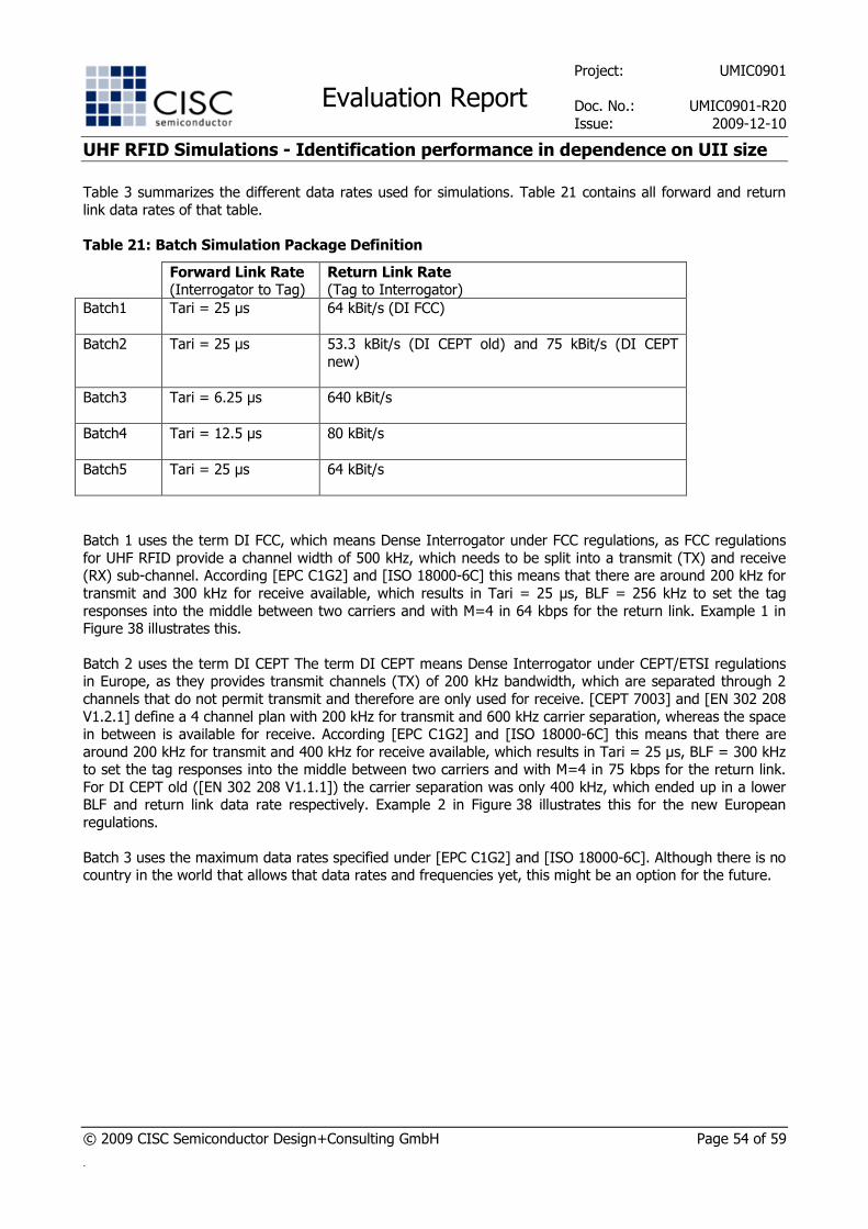
Project: UMIC0901
Evaluation Report Doc. No.: UMIC0901-R20
Issue: 2009-12-10
UHF RFID Simulations - Identification performance in dependence on UII size
© 2009 CISC Semiconductor Design+Consulting GmbH Page 54 of 59
.
Table 3 summarizes the different data rates used for simulations. Table 21 contains all forward and return
link data rates of that table.
Table 21: Batch Simulation Package Definition
Forward Link Rate (Interrogator to Tag)
Return Link Rate (Tag to Interrogator)
Batch1 Tari = 25 µs 64 kBit/s (DI FCC)
Batch2 Tari = 25 µs 53.3 kBit/s (DI CEPT old) and 75 kBit/s (DI CEPT
new)
Batch3 Tari = 6.25 µs 640 kBit/s
Batch4 Tari = 12.5 µs 80 kBit/s
Batch5 Tari = 25 µs 64 kBit/s
Batch 1 uses the term DI FCC, which means Dense Interrogator under FCC regulations, as FCC regulations
for UHF RFID provide a channel width of 500 kHz, which needs to be split into a transmit (TX) and receive (RX) sub-channel. According [EPC C1G2] and [ISO 18000-6C] this means that there are around 200 kHz for
transmit and 300 kHz for receive available, which results in Tari = 25 µs, BLF = 256 kHz to set the tag
responses into the middle between two carriers and with M=4 in 64 kbps for the return link. Example 1 in Figure 38 illustrates this.
Batch 2 uses the term DI CEPT The term DI CEPT means Dense Interrogator under CEPT/ETSI regulations in Europe, as they provides transmit channels (TX) of 200 kHz bandwidth, which are separated through 2
channels that do not permit transmit and therefore are only used for receive. [CEPT 7003] and [EN 302 208
V1.2.1] define a 4 channel plan with 200 kHz for transmit and 600 kHz carrier separation, whereas the space in between is available for receive. According [EPC C1G2] and [ISO 18000-6C] this means that there are
around 200 kHz for transmit and 400 kHz for receive available, which results in Tari = 25 µs, BLF = 300 kHz to set the tag responses into the middle between two carriers and with M=4 in 75 kbps for the return link.
For DI CEPT old ([EN 302 208 V1.1.1]) the carrier separation was only 400 kHz, which ended up in a lower BLF and return link data rate respectively. Example 2 in Figure 38 illustrates this for the new European
regulations.
Batch 3 uses the maximum data rates specified under [EPC C1G2] and [ISO 18000-6C]. Although there is no country in the world that allows that data rates and frequencies yet, this might be an option for the future.
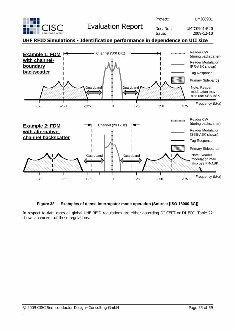
Project: UMIC0901
Evaluation Report Doc. No.: UMIC0901-R20
Issue: 2009-12-10
UHF RFID Simulations - Identification performance in dependence on UII size
© 2009 CISC Semiconductor Design+Consulting GmbH Page 55 of 59
.
0 125-125Frequency (kHz)
250 375-250-375
Example 1: FDMwith channel-boundary backscatter
Channel (500 kHz)
Reader Modulation(PR-ASK shown)
Tag Response
Primary Sidebands
GuardbandGuardband
Reader CW(during backscatter)
Note: Reader modulation may also use SSB-ASK
Example 2: FDM with alternative-channel backscatter
0 125 250-125-250Frequency (kHz)
Channel (200 kHz)
Reader Modulation(SSB-ASK shown)
Tag Response
Primary Sidebands
Reader CW(during backscatter)
Note: Reader modulation may also use PR-ASK
375-375
GuardbandGuardband
Figure 38 — Examples of dense-interrogator mode ope ration (Source: [ISO 18000-6C])
In respect to data rates all global UHF RFID regulations are either according DI CEPT or DI FCC. Table 22
shows an excerpt of those regulations.
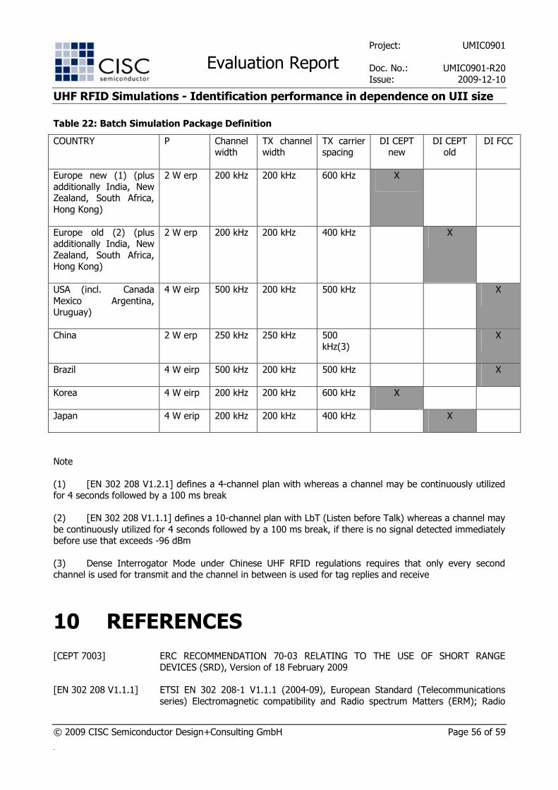
Project: UMIC0901
Evaluation Report Doc. No.: UMIC0901-R20
Issue: 2009-12-10
UHF RFID Simulations - Identification performance in dependence on UII size
© 2009 CISC Semiconductor Design+Consulting GmbH Page 56 of 59
.
Table 22: Batch Simulation Package Definition
COUNTRY P Channel width
TX channel width
TX carrier spacing
DI CEPT new
DI CEPT old
DI FCC
Europe new (1) (plus
additionally India, New Zealand, South Africa,
Hong Kong)
2 W erp 200 kHz 200 kHz 600 kHz X
Europe old (2) (plus additionally India, New
Zealand, South Africa, Hong Kong)
2 W erp 200 kHz 200 kHz 400 kHz X
USA (incl. Canada
Mexico Argentina, Uruguay)
4 W eirp 500 kHz 200 kHz 500 kHz X
China 2 W erp 250 kHz 250 kHz 500
kHz(3)
X
Brazil 4 W eirp 500 kHz 200 kHz 500 kHz X
Korea 4 W eirp 200 kHz 200 kHz 600 kHz X
Japan 4 W erip 200 kHz 200 kHz 400 kHz X
Note
(1) [EN 302 208 V1.2.1] defines a 4-channel plan with whereas a channel may be continuously utilized for 4 seconds followed by a 100 ms break
(2) [EN 302 208 V1.1.1] defines a 10-channel plan with LbT (Listen before Talk) whereas a channel may
be continuously utilized for 4 seconds followed by a 100 ms break, if there is no signal detected immediately before use that exceeds -96 dBm
(3) Dense Interrogator Mode under Chinese UHF RFID regulations requires that only every second channel is used for transmit and the channel in between is used for tag replies and receive
10 REFERENCES
[CEPT 7003] ERC RECOMMENDATION 70-03 RELATING TO THE USE OF SHORT RANGE
DEVICES (SRD), Version of 18 February 2009
[EN 302 208 V1.1.1] ETSI EN 302 208-1 V1.1.1 (2004-09), European Standard (Telecommunications
series) Electromagnetic compatibility and Radio spectrum Matters (ERM); Radio
Project: UMIC0901
Evaluation Report Doc. No.: UMIC0901-R20
Issue: 2009-12-10
UHF RFID Simulations - Identification performance in dependence on UII size
© 2009 CISC Semiconductor Design+Consulting GmbH Page 57 of 59
.
Frequency Identification Equipment operating in the band 865 MHz to 868 MHz
with power levels up to 2 W; All parts
[EN 302 208 V1.2.1] ETSI EN 302 208-1 V1.2.1 (2008-04), European Standard (Telecommunications
series) Electromagnetic compatibility and Radio spectrum Matters (ERM); Radio Frequency Identification Equipment operating in the band 865 MHz to 868 MHz
with power levels up to 2 W; All parts
[EPC C1G2] EPCglobal™ EPC™ Radio-Frequency Identity Protocols Class-1 Generation-2 UHF RFID Protocol for Communications at 860-960 MHz Version 1.2.0
[FCC 15.247] FCC PART 15 - RADIO FREQUENCY DEVICES, release of July 10, 2008, Section 15.247
[ISO/IEC 15962] Information technology -- Radio frequency identification (RFID) for item
management -- Data protocol: data encoding rules and logical memory functions
[ISO/IEC 18000-6REV1] Information technology -- Radio frequency identification for item management --
Part 6: Parameters for air interface communications at 860 MHz to 960 MHz
[ISO/IEC 18000-6:2004/Amd1:2006] Extension with Type C and update of Types A and B
[ISO 18000-6C] ISO/IEC 18000-6 Information technology — Radio frequency identification for item management — Part 6: Parameters for air interface communications at 860 MHz to
960 MHz, Amendment 1
[TDS 1.4] EPCglobal™ Tag Data Standards Version 1.4
[TDS 1.5] EPCglobal™ Tag Data Standards Version 1.5
[UMIC0901-R1] Evaluation Report UMIC0901-R1: UHF RFID Simulations - Identification performance in dependence on UII size"
Project: UMIC0901
Evaluation Report Doc. No.: UMIC0901-R20
Issue: 2009-12-10
UHF RFID Simulations - Identification performance in dependence on UII size
© 2009 CISC Semiconductor Design+Consulting GmbH Page 58 of 59
.
11 DISCLAIMER
Data sheet status
Objective specification This data sheet contains target or goal specifications for product development.
Preliminary specification This data sheet contains preliminary data; supplementary data may be published later.
Product specification This data sheet contains final product specifications.
Limiting values
Limiting values given are in accordance with the Absolute Maximum Rating System (IEC 134). Stress
above one or more of the limiting values may cause permanent damage to the device. These are stress
ratings only and operation of the device at these or at any other conditions above those given in the Characteristics section of the specification is not implied. Exposure to limiting values for extended periods
may affect device reliability.
Application information and User Manuals
Where application or use information is given, it is advisory and does not form part of the specification.
These products are not designed for use in life support appliances, devices, or systems where malfunction of
these products can reasonably be expected to result in personal injury. CISC Semiconductor Design+Consulting GmbH customers using or selling these products for use in such applications do so on
their own risk and agree to fully indemnify CISC Semiconductor Design+Consulting GmbH for any damages
resulting from such improper use or sale.
12 REVISION HISTORY
Table 23: Revision History
REVISION DATE PAGE DESCRIPTION
1.0 16.09.2009 Initial version.
1.1 02.12.2009 Editorial updates.
2.0 10.12.2009 Combining report and annexes into one document
NOTES
© CISC Semiconductor Design+Consulting GmbH. All rights reserved. Reproduction in whole or in parts is prohibited without the prior written consent of the copyright owner. The information presented in this document does not form part of any quotation or contract, is believed to be accurate and reliable and may be changed without notice. No liability will be accepted by the publisher for any consequence of its use. Publication thereof does not convey or imply any license under patent or other industrial or intellectual property rights.
SyAD® and CISC RFID Field Recorder® are registered trademarks of CISC Semiconductor. Other products or brand names are trademark or registered trademarks of their respective holders.
CISC Semiconductor Design+Consulting GmbH | Lakeside B07, 9020 Klagenfurt, Austria | www.cisc.at
About CISC Semiconductor
CISC Semiconductor Design+Consulting GmbH is a design and consulting service company for industries
developing embedded microelectronic systems with extremely short Time-To-Market cycles. Our core competences are: System design, modeling, simulation, verification and optimization of heterogeneous
embedded microelectronic systems with a particular focus on Automotive and RFID systems. Our customers are coming from Semiconductor, Automotive, and RFID industry.
The company was founded in 1999 and is 100% private owned. CISC is managed by an international team
of highest skilled experts. Our main office is situated in Klagenfurt, Austria (close to well known Wörthersee) at the heart of the Alpe-Adria-Region. We are proud to be able to conduct our international business from
this part of the world and also enjoy our life with our families and friends within this beautiful nature.
Being an independent company CISC furthermore is able to provide non CAD/CAE market driven technology
for individual customer solutions. CISC offers commercial tools and techniques for simulation based system development of embedded microelectronic systems including RFID systems.