development of a design and performance...
TRANSCRIPT

T. Katsura *1 K. Nagano*1 S. Takeda *1 T. Ibamoto *1
S. Narita *1 Y.Nakamura *2 N. Homma *3
*1 Hokkaido University*2 Nippon Steel Corporation*3 Hokkaido Electric Power Co., Inc
1/33
DEVELOPMENT OF A DESIGN AND PERFORMANCE PREDICTION TOOL FOR
THE GROUND SOURCE HEAT PUMP SYSTEM

Background 2/33
The Kyoto protocol became effective at 16th February 2005CO2 emissions reduction target of Japan 6%
The number of the GSHP systems installed in Japan is increasing rapidly
05
1 01 52 02 53 03 54 0
1981
1983
1985
1987
1989
1991
1993
1995
1997
1999
2001
2003
Uni
ts
Markets of the GSHP in Japan
The GSHP system has been remarked as a system with large potential for reduction of CO2 emission.
2004
T. Katsura, et al. IEAs 10th Energy Conservation Thermal Energy Storage Conference Ecostock’2006, New Jersey, USA, 2006. 6. 2

Background 3/33
When the GSHP system is installed, a design tool is required.The tool is used for…
no design tool in Japan
Determination of length of the ground heat exchanger
?
Demonstration of installing effect of the GSHP system
Oilboiler
GSHP system
?CO
2em
issi
ons
We developed a design tool for the GSHP system
T. Katsura, et al. IEAs 10th Energy Conservation Thermal Energy Storage Conference Ecostock’2006, New Jersey, USA, 2006. 6. 2

Advantages of the developed tool
1. User friendly data input procedure and graphical output
5. Including database of CO2 emissions, costs, and lifetimes for LCA
2. Short time calculation according to hourly heating and cooling loads(Calculation time is approx. 1 minute for calculation of two years’ operation)
6. High speed calculation algorithm for heat extraction or injection of the multiple ground heat exchangers buried in random layout
3. Calculation of internal thermal resistance in a borehole for tube geometric arrangement by the boundary element method (BEM)
4. Calculation of the heat carrier fluid in the ground heat exchanger with large diameter
T. Katsura, et al. IEAs 10th Energy Conservation Thermal Energy Storage Conference Ecostock’2006, New Jersey, USA, 2006. 6. 2
4/33

Examples of the input and output screens and windows(1) Input windows
(2) Output windows
Calculations are carried out. Then right window is displayed
Output window examples
T. Katsura, et al. IEAs 10th Energy Conservation Thermal Energy Storage Conference Ecostock’2006, New Jersey, USA, 2006. 6. 2
5/33

Calculation of ground temperature
Nomenclature a: Thermal diffusivity [m2/s], Jx: xth-order Bessel function of first kind, q’ : Heat flux [W/m2], r: Radius [m], T: Temperature [oC], t: Time [h], u: Characteristic value, Yx: xth-order Bessel function of second kindSubscripts b: Borehole surface, s: Soil Greek letters λ: Thermal conductivity [W/m/K]
Ts0
Ts
Ts0
Ts
rprp
Ground temperature calculation applying the cylindrical heat source theory
Infinite solid
hollow cylinder
Infinite solid
hollow cylinder
qboqbo
Theoretical solution of the ground temperature variation Ts according to radius rand uncertain time t
The developed tool uses an approximate expression of this response for making superposition Fast calculation
duruYruJu
ruJurYruYurJeq
TTbobo
bobotusa
s
boss ∫
+−
−−=∞
−
021
21
2
101020 )]()([
)()()()()1(2πλ
X
Vertical ground heat excahgner
6/33

Calculation of the GSHP system operation
Heat capacity change: ΔQb
T1out
T1in
Tb
Heat extraction from ground heat exchanger: Q1
Compressor power: E
Ts
T2out
Heat extraction from ground: Qbo
Flow rate: mb
Heat load: Q2
T2in
rrTbo
s =
Overall heat transfer coefficient : Kbo-out
Heat capacity change: ΔQb
T1out
T1in
Tb
Heat extraction from ground heat exchanger: Q1
Compressor power: E
Ts
T2out
Heat extraction from ground: Qbo
Flow rate: mb
Heat load: Q2
T2in
rrTbo
s =
Overall heat transfer coefficient : Kbo-out
Calculation diagram of a typical GSHP system
1
1 Radiator
1
1 Radiator
2
2 Heat pump unit
2
2 Heat pump unit
3 3 Ground heat exchanger
3 3 Ground heat exchanger
Nomenclature T: Temperature [oC]Subscripts bo: Borehole surface, b: Heat carrier fluid (antifreeze solution or water), in: Inlet of heat pump unit, out: Outlet of heat pump unit, 1: Primary side, 2: Secondary side
T. Katsura, et al. IEAs 10th Energy Conservation Thermal Energy Storage Conference Ecostock’2006, New Jersey, USA, 2006. 6. 2
7/33

Example of temperature distribution calculated by BEMSingle U-tube(λbo=1.8W/m/K)
Double U-tube(λbo=1.8W/m/K)
1.0
0.0
0.2
0.4
0.6
0.832 52
120
32 72
120
32 52
120
32 72
120
Nomenclature Rb: Borehole thermal resistance [m2/K/W]
Rbo=2.23×10⁻² m2/W/K Rbo=1.35×10⁻² m2/W/K
Rbo=1.52×10⁻² m2/W/K Rbo=7.58×10⁻³ m2/W/K
Case 1 Case 2
Case 1 Case 2
T. Katsura, et al. IEAs 10th Energy Conservation Thermal Energy Storage Conference Ecostock’2006, New Jersey, USA, 2006. 6. 2
8/33
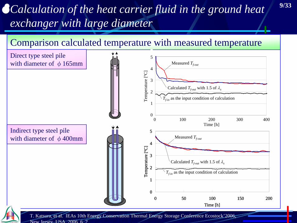
Calculation of the heat carrier fluid in the ground heat exchanger with large diameterComparison calculated temperature with measured temperature
Calculated Tf-out with 1.5 of λs
Tf-in as the input condition of calculation
0 100 200 300 400Time [h]
5
4
3
2
1
0
Tem
pera
ture
[ºC
]
Measured Tf-out
Calculated Tf-out with 1.5 of λs
Tf-in as the input condition of calculation
0 100 200 300 400Time [h]
5
4
3
2
1
0
Tem
pera
ture
[ºC
]
Measured Tf-out
0
1
2
3
4
5
0 50 100 150 200Time [h]
Tem
pera
ture
[ºC
]
Calculated Tf-out with 1.5 of λs
Tf-in as the input condition of calculation
Measured Tf-out
0
1
2
3
4
5
0 50 100 150 200Time [h]
Tem
pera
ture
[ºC
]
Calculated Tf-out with 1.5 of λs
Tf-in as the input condition of calculation
Measured Tf-out
Direct type steel pilewith diameter of φ165mm
Indirect type steel pilewith diameter of φ400mm
T. Katsura, et al. IEAs 10th Energy Conservation Thermal Energy Storage Conference Ecostock’2006, New Jersey, USA, 2006. 6. 2
9/33

Life cycle analysis of the GSHP system
Life cycle analysis•Life cycle assessment•Estimation of life cycle cost
These are estimated by
Total initial + Total running
Lifetime
Electric power consumption
(Calculated by the GSHP system operation )
This tool can also compare the GSHP system with conventional systems (ex.Oil boiler system, ASHP)
Energy consumptionCO2 emission
A database of CO2 emissions, costs, andlifetimes for LCA is included in the tool
T. Katsura, et al. IEAs 10th Energy Conservation Thermal Energy Storage Conference Ecostock’2006, New Jersey, USA, 2006. 6. 2
10/33

Calculation for multiple ground heat exchangers
Input window of pipe arrangement of multiple ground heat exchangers
HP
2m
Steel foundation pile used as ground heat exchanger
Header
2m2m
2m 2m 2m 2m 2m
Piping route of CASE1 Piping route of CASE2
Input
T. Katsura, et al. IEAs 10th Energy Conservation Thermal Energy Storage Conference Ecostock’2006, New Jersey, USA, 2006. 6. 2
11/33

Examples of the calculation results
Difference of temperature distributions according to pipe arrangement
Elapsed time of 3000 h (Mar.7th) Elapsed time of 5000 h (May. 30th)
Piping route
CASE1 CASE1 CASE1
CASE2 CASE2 CASE2
Elapsed time of 7000 h (Aug. 21st)
1
15.015.0
10.010.0
10.010.0
15.015.0
15.015.0
10.010.0
10.010.0
15.015.0 15.015.0
15.015.015.015.0
15.015.0 15.015.0
15.015.0
20.020.0
20.020.0
23
4
5
1
23
4
5
5 10 15 20Temperature [oC]
T. Katsura, et al. IEAs 10th Energy Conservation Thermal Energy Storage Conference Ecostock’2006, New Jersey, USA, 2006. 6. 2
12/33

Advantages of the developed tool
1. User friendly data input procedure and graphical output
5. Including database of CO2 emissions, costs, and lifetimes for LCA
2. Short time calculation according to hourly heating and cooling loads(Calculation time is approx. 1 minute for calculation of two years’ operation)
6. High speed calculation algorithm for heat extraction or injection of the multiple ground heat exchangers buried in random layout
3. Calculation of internal thermal resistance in a borehole for tube geometric arrangement by the boundary element method (BEM)
4. Calculation of the heat carrier fluid in the ground heat exchanger with large diameter
T. Katsura, et al. IEAs 10th Energy Conservation Thermal Energy Storage Conference Ecostock’2006, New Jersey, USA, 2006. 6. 2
13/33
Especially effective to evaluate the performance of the GSHP system, which is From these advantages, this tool is…
the large systems and the energy pile systems

Today’s topics 14/33
1. Calculation of temperatures of the ground and the heat carrier fluid in the GSHP system for the multiple ground heat exchangers
• High speed calculation algorithm of the ground temperature for heat extraction or heat injection of multiple ground heat exchangers• Calculation method of temperature of the heat carrier fluid in the GSHP system for pipe arrangement of the ground heat exchangers
2. Comparison of performance of the GSHP system
• Piping route
• Numbers of the parallel and serial circuits
• Number of the ground heat exchangers (But the total lengths are the same)
• Method of calculation (Detailed method and simplified method)
The calculated conditions are changed for the comparison items
T. Katsura, et al. IEAs 10th Energy Conservation Thermal Energy Storage Conference Ecostock’2006, New Jersey, USA, 2006. 6. 2
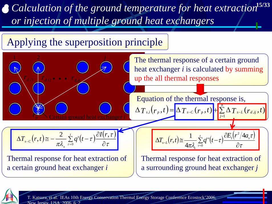
Calculation of the ground temperature for heat extraction or injection of multiple ground heat exchangers
15/33
Applying the superposition principle1 2 j
Certain ground heat exchanger i
rd,ijrd,i2rd,i1 ・・・
rp
1 2 j
Certain ground heat exchanger i
rd,ijrd,i2rd,i1 ・・・
rp
The thermal response of a certain ground heat exchanger i is calculated by summing up the all thermal responses
Equation of the thermal response is, ( ) ∑ ∆+∆=∆
=−−
n
jijdLspCspis trTtrTtrT
1,, ),(),(,
( ) ( ) ( )∑
∂∂
−−≅∆=
−
t
sCs
rItqtrT0
,'2,τ τ
ττπλ ( ) ( ) ( )
∑∂
∂−≅∆
=−
ts
sLs
arEtqtrT
0
21 4
''4
1,τ τ
ττ
πλ
Thermal response for heat extraction of a certain ground heat exchanger i
Thermal response for heat extraction of a surrounding ground heat exchanger j
T. Katsura, et al. IEAs 10th Energy Conservation Thermal Energy Storage Conference Ecostock’2006, New Jersey, USA, 2006. 6. 2

Non-dimensional thermal response for heat extraction of a certain ground heat exchanger i
Non-dimensional thermal response for heat extraction of a surrounding ground heat exchanger j
Applying superposition of the approximated thermal response for the cylindrical heat source
Approximating the superposed thermal response for the line heat source
( ) ( ) ( )∑
∂∂
−=∆=
−−
*
0* *
********* ,
,t
CsCs
rTtqtrT
τ ττ
τ ( ) ( ) ( )∑
∂∂
−=∆=
−−
*
0* *
********* ,,
tLs
Ls
rTtqtrTτ τ
ττ
Approximate equation (t* ≥ 1.0 )( ) ( ) ( )
( )∑∂
∂−+∑∆≅∆
=
−
=−−
*
1* 2**
2******
1
**** ,1,t
Csn
iLisLs r
rTtqTtrTτ τ
ττ
The ground temperature can be calculated with acceptable precision and speed to be used as a tool for designing of the GSHP system
Calculation of the ground temperature for heat extraction or injection of multiple ground heat exchangers
16/33
Ts* : Non-dimensional temperature (= 2πλsΔTs / rp / q’’) [-], t* : Fourier number (= at / rp
2) [-], q* : Non-dimensional heat flux (= q / q0) [-], q0 : Unit heat flux (=1) [W/m2],
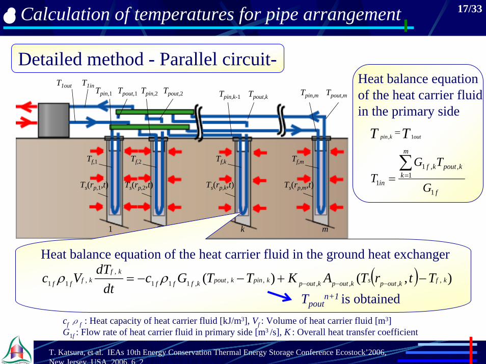
Calculation of temperatures for pipe arrangement 17/33
Detailed method - Parallel circuit-Tpin,1 Tpin,2 Tpin,k-1 Tpin,m Tpout,m
1 2 k m
Ts(rp,1,t) Ts(rp,2,t) Ts(rp,k,t) Ts(rp,m,t)
Tf,1 Tf,2 Tf,k Tf,m
Tpout,1 Tpout,2 Tpout,k
T1inT1out
( ) ),()( ,,,,,,,111
,,11 kfkoutpskoutpkoutpkpinkpoutkfff
kfkfff TtrTAKTTGc
dtdTVc −+−−= −−−ρρ
Heat balance equation of the heat carrier fluid in the ground heat exchanger
Tpoutn+1 is obtained
TT outkpin 1, =
f
m
kkpoutkf
in G
TGT
1
1,,1
1
∑==
Heat balance equation of the heat carrier fluid in the primary side
T. Katsura, et al. IEAs 10th Energy Conservation Thermal Energy Storage Conference Ecostock’2006, New Jersey, USA, 2006. 6. 2
cfρf : Heat capacity of heat carrier fluid [kJ/m3], Vf : Volume of heat carrier fluid [m3]G1f : Flow rate of heat carrier fluid in primary side [m3 /s], K : Overall heat transfer coefficient
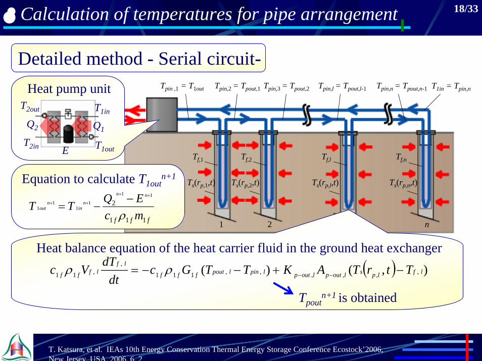
Calculation of temperatures for pipe arrangement 18/33
Detailed method - Serial circuit-Tpin ,1 = T1out Tpin,3 = Tpout,2Tpin,2 = Tpout,1 Tpin,l = Tpout,l-1 Tpin,n = Tpout,n-1 T1in = Tpin,n
1 2 l n
Ts(rp,1,t) Ts(rp,2,t) Ts(rp,l,t) Ts(rp,n,t)
Tf,1 Tf,2 Tf,l Tf,n
Q2 Q1
E T1out
T1inT2out
T2in
Heat pump unit
fff mcEQTT
nn
nin
nout
111
211
11
11
ρ
++
++ −−=
Equation to calculate T1outn+1
( ) ),()( ,,,,,,111
,,11 lflpsloutploutplpinlpoutfff
lflfff TtrTAKTTGc
dtdTVc −+−−= −−ρρ
Tpoutn+1 is obtained
Heat balance equation of the heat carrier fluid in the ground heat exchanger
T. Katsura, et al. IEAs 10th Energy Conservation Thermal Energy Storage Conference Ecostock’2006, New Jersey, USA, 2006. 6. 2

Calculation of temperatures for pipe arrangement 19/33
Simplified method
Heat pump
1
Supply and return header
2 3 … n - 1 n1
2
…
m - 1
m
Heat pump
1
Supply and return header
2 3 … n - 1 n1
2
…
m - 1
m
A. Serial circuit The ground heat exchangers are
regarded as a ground heat exchanger whose length is equal to the total length of the ground heat exchangers
B. Parallel circuit The flow rate is divided into according number of the parallel circuit
From A and B, the following equation is obtained as respects all circuits
( ) ),()( 111
1111 fpsoutpoutpoutinf
ff
ffff TtrTnAKTT
mG
cdt
dTnVc −+−−= −−ρρ
T. Katsura, et al. IEAs 10th Energy Conservation Thermal Energy Storage Conference Ecostock’2006, New Jersey, USA, 2006. 6. 2

Comparison of performance of the GSHP system 20/33
Heat loss coefficient:2.33W/m2/K
Floor area: 130m2
Initial ground temperature: 16.5 oC Soil heat capacity: 3000 kJ/m3
Soil thermal conductivity: 1.0 W/m/K
Location : Tokyo, Japan
Cooling period: Apr.23rd - Nov.2ndHeating period: Nov.3rd - Apr.22nd
Heating load: 28.2 GJ(Maximum load: 6.6 kW) Cooling load: 10.0 GJ(Maximum load: 6.3 kW)
Room conditionHeating periodTemperature: 20oCCooling period Temperature: 26oCHumidity: 50%
Calculated subject
T. Katsura, et al. IEAs 10th Energy Conservation Thermal Energy Storage Conference Ecostock’2006, New Jersey, USA, 2006. 6. 2

Comparison of performance of the GSHP system 21/33
Hourly variation of heat load
Nov. 3rd Feb. 3rd May. 3rd Aug. 3rd Nov. 2ndNov. 3rd Feb. 3rd May. 3rd Aug. 3rd Nov. 2nd
-8
-6
-4
-2
0
2
4
6
8
Hea
t loa
d [k
W]
Heating period Cooling period
Heating load
Cooling load
Heating load: 28.2 GJ(Maximum load: 6.6 kW) Cooling load: 10.0 GJ(Maximum load: 6.3 kW)
T. Katsura, et al. IEAs 10th Energy Conservation Thermal Energy Storage Conference Ecostock’2006, New Jersey, USA, 2006. 6. 2

Calculated conditions 22/33
Pipe arrangement(Parallel × Serial)
Method forcalculation
CASE1 4 × 5 Detailed methodCASE2 4 × 5 Detailed methodCASE3 20 × 1 Detailed methodCASE4 1×1 (Borehole) Detailed methodCASE5 4 × 5 Simplified method
T. Katsura, et al. IEAs 10th Energy Conservation Thermal Energy Storage Conference Ecostock’2006, New Jersey, USA, 2006. 6. 2

23/33Comparison items
HP
2m
Header
2m2m
2m 2m 2m 2m 2m
CASE 1
Piping route: CASE1 vs. CASE2
CASE 2
Steel foundation pile used as ground heat exchanger
HP
2m
Header
2m2m
2m 2m 2m 2m 2m
1
2 3 4
5 5
4 3 2
1
T. Katsura, et al. IEAs 10th Energy Conservation Thermal Energy Storage Conference Ecostock’2006, New Jersey, USA, 2006. 6. 2

Comparison item 24/33
CASE 1: Numbers of the parallel × serial circuits are 4 × 5
Numbers of the parallel and serial circuits : CASE1 vs. CASE3
CASE 1: Multiple ground heat exchangers of 8 m × 20 (= 160 m)
Number of the ground heat exchangers : CASE1 vs. CASE4
CASE 3: All ground heat exchangers are connected in parallel
CASE 1: Calculated by the detailed method
Method of calculation : CASE1 vs. CASE5
CASE 4: A single ground heat exchanger with length of 160 m
CASE 5: Calculated by the simplified method
T. Katsura, et al. IEAs 10th Energy Conservation Thermal Energy Storage Conference Ecostock’2006, New Jersey, USA, 2006. 6. 2

25/33An example of calculation results
Operating condition (temperature variations*) of the third year
-10
0
10
20
30
40
50
Tem
pera
ture
[o C]
Nov.3rd Feb.3rd May.3rd Aug.3rd Nov. 2ndNov.3rd Feb.3rd May.3rd Aug.3rd Nov. 2nd
T2out
T1out
Tp-outave
Heating Period Cooling Period
T1out
T2outTp-outave
*Temperatures of each part
T1in
T1out
T2out
Tp-out
T1in
T1out
T2out
Tp-out
Minimum temperature:-0.4oC Temperatures are recovered
The GSHP system can operate for a long term
T. Katsura, et al. IEAs 10th Energy Conservation Thermal Energy Storage Conference Ecostock’2006, New Jersey, USA, 2006. 6. 2

Comparison between CASE1 and CASE2 26/33
Changes of temperature distribution in the ground surrounding piles
Elapsed time of 3000 h (Mar.7th) Elapsed time of 5000 h (May. 30th)
Piping route
CASE1 CASE1 CASE1
CASE2 CASE2 CASE2
Elapsed time of 7000 h (Aug. 21st)
1
15.015.0
10.010.0
10.010.0
15.015.0
15.015.0
10.010.0
10.010.0
15.015.0 15.015.0
15.015.015.015.0
15.015.0 15.015.0
15.015.0
20.020.0
20.020.0
23
4
5
5
43
2
1
5 10 15 20Temperature [oC]
1
2 3 4
5 1
2 3 4
5
5
43
2
1 5
43 2
1
Temperature decrement: Almost even
Temperature decrement: Pile1 is the largest
Temperature increment: Pile1 is the largest
Temperature increment: Pile1 is the largest
Ground temperature is decreased
Effect of heat extraction is still leftT. Katsura, et al. IEAs 10th Energy Conservation Thermal Energy Storage Conference Ecostock’2006, New Jersey, USA, 2006. 6. 2

Comparison between CASE1 and CASE2 27/33
Integrating amounts of heat extraction and injection of each pile
-1.5
-1.0
-0.5
0.0
0.5
1.0
1.5
Am
ount
of h
eat e
xtra
ctio
n [G
J]
Pile2, Pile1, Pile 3, Pile 4, Pile5 from top to bottom
Total amount of heat extraction:5.65GJTotal amount of heat injection :2.87GJ
Heating Period Cooling Period
Pile2, Pile3, Pile 4, Pile 1, Pile5 from top to bottom
Nov.3rd Feb.3rd May.3rd Aug.3rd Nov.2ndNov.3rd Feb.3rd May.3rd Aug.3rd Nov.2nd-1.5
-1.0
-0.5
0.0
0.5
1.0
1.5
Am
ount
of h
eat e
xtra
ctio
n [G
J] Total amount of heat extraction:5.65GJTotal amount of heat injection :2.87GJ
Nov.3rd Feb.3rd May.3rd Aug.3rd Nov.2ndNov.3rd Feb.3rd May.3rd Aug.3rd Nov.2nd
Heating Period Cooling Period
Pile5, Pile1, Pile 4, Pile 3, Pile2 from top to bottom
Pile4, Pile5, Pile 3, Pile 2, Pile1 from top to bottom
Difference: Large Difference: Small
Difference: LargeDifference: Small
1. Seasonal thermal storage effect appearsThese results indicate…
2. Total amounts of heat extraction are the same although the ones of individual piles differ depending on the piping route
T. Katsura, et al. IEAs 10th Energy Conservation Thermal Energy Storage Conference Ecostock’2006, New Jersey, USA, 2006. 6. 2

Comparison between CASE1 and CASE2 28/33
Performance of the GSHP system
AverageCOP
AverageSCOP
AverageCOP
AverageSCOP
CASE1 5.0 4.0 5.6 3.6CASE2 5.0 4.0 5.6 3.6CASE3 4.9 3.9 5.5 3.5CASE4 5.4 4.2 5.3 3.4CASE5 5.0 4.0 5.6 3.6
Heating Period Cooling Period
These results indicate…
In this calculated condition, difference of the performance of the GSHP system for the piping route is hardly occurred
T. Katsura, et al. IEAs 10th Energy Conservation Thermal Energy Storage Conference Ecostock’2006, New Jersey, USA, 2006. 6. 2

Comparison between CASE1 and CASE3 29/33
Performance of the GSHP system
These results indicate…Laminar flow of the heat carrier fluid yields reduction of heat extractionor injection and performance decrement of the GSHP system
AverageCOP
AverageSCOP
AverageCOP
AverageSCOP
CASE1 5.0 4.0 5.6 3.6CASE2 5.0 4.0 5.6 3.6CASE3 4.9 3.9 5.5 3.5CASE4 5.4 4.2 5.3 3.4CASE5 5.0 4.0 5.6 3.6
Heating Period Cooling Period
It’s desirable to arrange the piping route to keep the turbulent flowT. Katsura, et al. IEAs 10th Energy Conservation Thermal Energy Storage Conference Ecostock’2006, New Jersey, USA, 2006. 6. 2

Comparison between CASE1 and CASE4 30/33
Performance of the GSHP system
These results indicate…The GSHP with multiple ground heat exchangers can operate with highefficiency as well as the system with a single ground heat exchanger
AverageCOP
AverageSCOP
AverageCOP
AverageSCOP
CASE1 5.0 4.0 5.6 3.6CASE2 5.0 4.0 5.6 3.6CASE3 4.9 3.9 5.5 3.5CASE4 5.4 4.2 5.3 3.4CASE5 5.0 4.0 5.6 3.6
Heating Period Cooling Period
The GSHP system has potential to be popular in warm region in Japan
T. Katsura, et al. IEAs 10th Energy Conservation Thermal Energy Storage Conference Ecostock’2006, New Jersey, USA, 2006. 6. 2

Comparison between CASE1 and CASE5 31/33
Performance of the GSHP system
These results indicate…
The simplified method provides high advantage from the viewpoint ofprecision and computational speed for evaluation of the GSHP system
AverageCOP
AverageSCOP
AverageCOP
AverageSCOP
CASE1 5.0 4.0 5.6 3.6CASE2 5.0 4.0 5.6 3.6CASE3 4.9 3.9 5.5 3.5CASE4 5.4 4.2 5.3 3.4CASE5 5.0 4.0 5.6 3.6
Heating Period Cooling Period
T. Katsura, et al. IEAs 10th Energy Conservation Thermal Energy Storage Conference Ecostock’2006, New Jersey, USA, 2006. 6. 2

Summary 32/33
1. Calculation algorithm of temperatures for pipe arrangement of the multiple ground heat exchangers is shown• High speed calculation algorithm of the ground temperature for heat extraction or heat injection of multiple ground heat exchangers• Calculation method of the heat carrier fluid in the GSHP system for pipe arrangement of the ground heat exchangers
T. Katsura, et al. IEAs 10th Energy Conservation Thermal Energy Storage Conference Ecostock’2006, New Jersey, USA, 2006. 6. 2
Summary 33/33
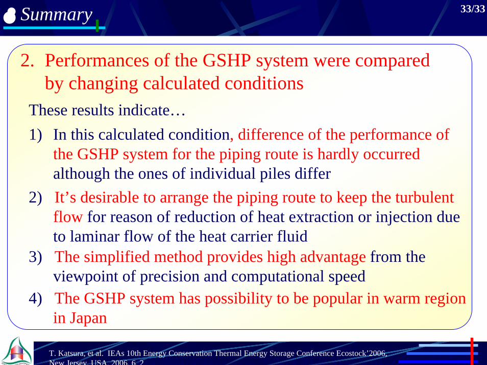
2. Performances of the GSHP system were compared by changing calculated conditions
These results indicate…1) In this calculated condition, difference of the performance of
the GSHP system for the piping route is hardly occurred although the ones of individual piles differ
2) It’s desirable to arrange the piping route to keep the turbulent flow for reason of reduction of heat extraction or injection due to laminar flow of the heat carrier fluid
3) The simplified method provides high advantage from the viewpoint of precision and computational speed
4) The GSHP system has possibility to be popular in warm region in Japan
T. Katsura, et al. IEAs 10th Energy Conservation Thermal Energy Storage Conference Ecostock’2006, New Jersey, USA, 2006. 6. 2

Thank you for your attention !!

Comparison between temperatures of the calculation and measurement in field experiments
Work Shop of Annex29, 2005-05-30, Las Vegas, USAK. Nagano, T. Katsura, S. Takeda et al.
35/25
In experiment room
To outside To outside
Heat pump Fan-coil
Experiment room
Flow sensor Electromagnetic flow meterF T Pt-100
Steel pile
Water
Brine (Acid organic type 40 %)
U-tube (PE100)
External diameter: 140 mm
8m
Internal diameter: 130 mm
External diameter: 32 mm
Internal diameter: 25 mm
Schematic diagram of the field experiments
Comparison between temperatures of the calculation and measurement in field experiments
Work Shop of Annex29, 2005-05-30, Las Vegas, USAK. Nagano, T. Katsura, S. Takeda et al.
36/25
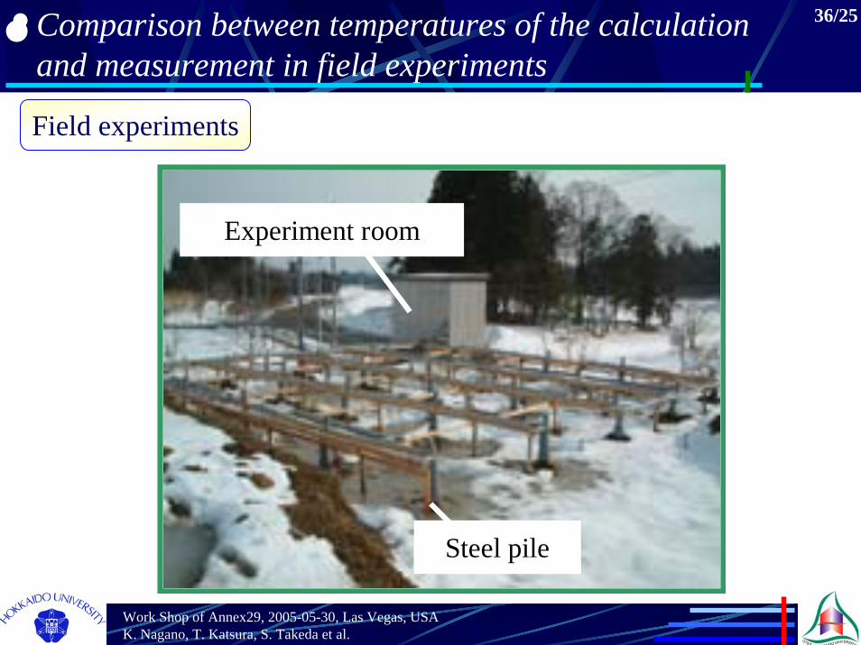
Field experiments
Experiment room
Steel pile
Comparison between temperatures of the calculation and measurement in field experiments
Work Shop of Annex29, 2005-05-30, Las Vegas, USAK. Nagano, T. Katsura, S. Takeda et al.
37/25
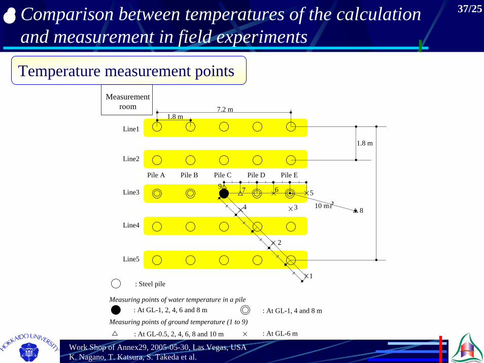
Temperature measurement points
Line4
Line1
Line2
Line3
Line5
1.8 m
Measurement room
7 6 5
4 3
2
1
8
: At GL-1, 2, 4, 6 and 8 m
: At GL-0.5, 2, 4, 6, 8 and 10 m
1.8 m7.2 m
: At GL-1, 4 and 8 m
: At GL-6 m
: Steel pile
Measuring points of water temperature in a pile
Measuring points of ground temperature (1 to 9)
9
10 m
Pile A Pile B Pile C Pile D Pile E
Comparison between temperatures of the calculation and measurement in field experiments
Work Shop of Annex29, 2005-05-30, Las Vegas, USAK. Nagano, T. Katsura, S. Takeda et al.
38/25
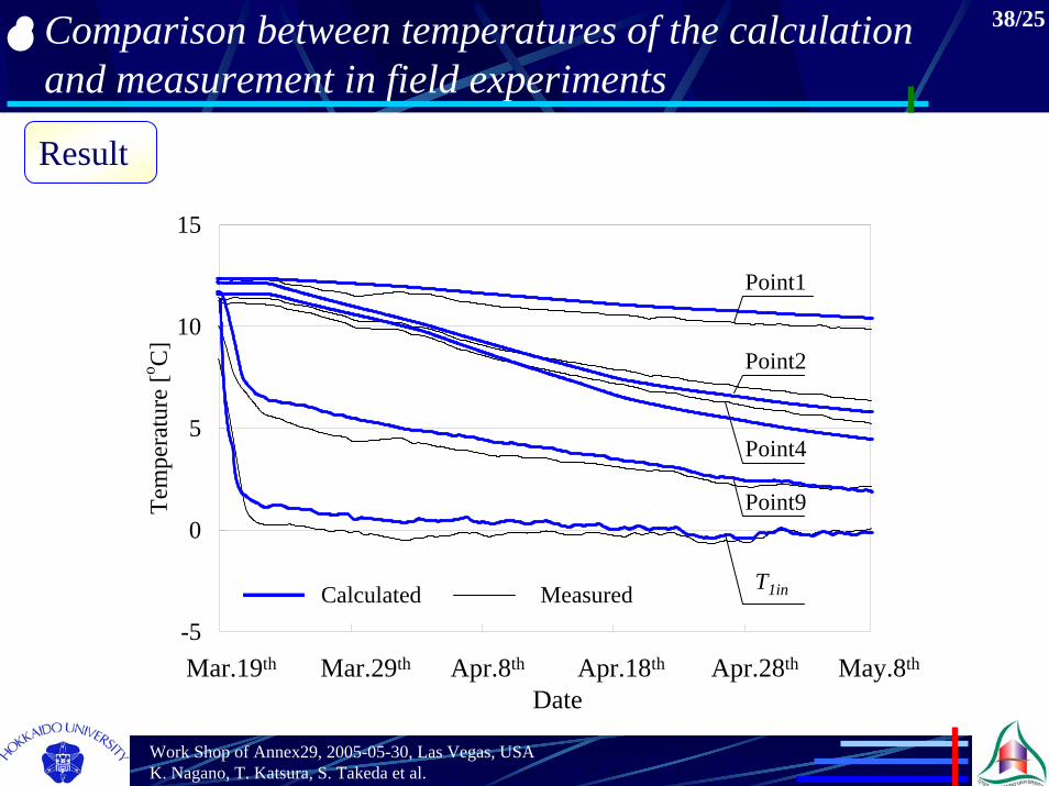
Result
DateMar.19th Mar.29th Apr.8th Apr.18th Apr.28th May.8th
-5
0
5
10
15
Tem
pera
ture
[o C]
MeasuredCalculated T1in
Point9
Point4
Point2
Point1