development of a performance-based design approach and
TRANSCRIPT

Louisiana State UniversityLSU Digital Commons
LSU Master's Theses Graduate School
2003
Development of a performance-based designapproach and related loads for facilities designatedas essential during a hurricane eventJoffrey Elliott EasleyLouisiana State University and Agricultural and Mechanical College, [email protected]
Follow this and additional works at: https://digitalcommons.lsu.edu/gradschool_theses
Part of the Civil and Environmental Engineering Commons
This Thesis is brought to you for free and open access by the Graduate School at LSU Digital Commons. It has been accepted for inclusion in LSUMaster's Theses by an authorized graduate school editor of LSU Digital Commons. For more information, please contact [email protected].
Recommended CitationEasley, Joffrey Elliott, "Development of a performance-based design approach and related loads for facilities designated as essentialduring a hurricane event" (2003). LSU Master's Theses. 3581.https://digitalcommons.lsu.edu/gradschool_theses/3581

DEVELOPMENT OF A PERFORMANCE-BASED DESIGN APPROACH AND RELATED LOADS FOR FACILITIES
DESIGNATED AS ESSENTIAL DURING A HURRICANE EVENT
A Thesis
Submitted to the Graduate Faculty of the Louisiana State University and
Agricultural and Mechanical College in partial fulfillment of the
requirements for the degree of Master of Science in Civil Engineering
in
The Department of Civil and Environmental Engineering
by Joffrey Elliott Easley
B.S., Louisiana State University, 2000 May 2003

ACKNOWLEDGEMENTS There are a number of people that need to be thanked for assistance in the
development of this thesis. The author would first like to thank the Board of Regents of the
State of Louisiana, who provided funding, in the form of a Graduate Fellowship, which
allowed the author the opportunity to further his education and obtain his Master’s Degree.
The author would also like to thank Dr. Marc Levitan, his advisor, who has been very helpful
in the realization of this thesis. Additional gratitude is extended to the other members of the
author’s graduate committee; Dr. Steve Cai, Dr. Dante Fratta, and Dr. Ivor, van Heerden.
Thanks are also given to the other members of the faculty of LSU for their assistance in
furthering the author’s education. Gratefulness is also extended to the author’s coworkers at
GEC, Inc., who have provided him the freedom to finish this thesis. The author would also
like to thank Mr. Joey Coco, who was helpful in the initial development of this thesis.
Last, but certainly not least, the author would like to thank his family. The author
would first like to extend a heartfelt thanks to his wife, who has been very understanding and
helpful during the completion of his thesis and who has given a great deal of love and
support to help in the completion of this thesis. Also, the author would like to thank his
loving parents, John and Judy Easley, who have always been there to provide the love and
guidance needed to achieve whatever goals their children set. The author would also like to
thank his sister, Kim Easley, for her never-failing love.
ii

TABLE OF CONTENTS ACKNOWLEDGEMENTS…………………………………………………………………...ii LIST OF TABLES……………………………………………………………………………vi LIST OF FIGURES…………………………………………………………………………viii ABSTRACT…………………………………………………………………………………...x CHAPTER 1: INTRODUCTION…………………………………………………………….1
1.1 Background…………………………………………………………………………1 1.2 Problem Statement………………………………………………………………….2 1.3 Goals and Objectives……………………………………………………………….3
CHAPTER 2: LITERATURE REVIEW……………………………………………………..7
2.1 The Hurricane Event………………………………………………………………..7 2.1.1 Life Cycle……………………………………………………………………...7 2.1.2 The Mature Hurricane………………………………………………………..11
2.2 Performance-Based Design………………………………………………………..16 2.2.1 Background…………………………………………………………………..16 2.2.2 Existing Performance-Based Design Manuals……………………………….18 2.2.3 Consequence-Based Engineering – A New Form of Performance-Based
Design………………………………………………………………………..28 2.2.4 Summary……………………………………………………………………..29
2.3 Wind, Wind Load, and Load Combinations………………………………………30 2.3.1 ANSI A58.1-1982……………………………………………………………30 2.3.2 ASCE 7-88…………………………………………………………………...30 2.3.3 ASCE 7-93…………………………………………………………………...34 2.3.4 ASCE 7-95…………………………………………………………………...35 2.3.5 ASCE 7-98…………………………………………………………………...39 2.3.6 ASCE 7-02…………………………………………………………………...44 2.3.7 Additional Recent Research on Hurricane Wind Speed, Distributions, and
Load Factors………………………………………………………………….44 2.3.8 Summary……………………………………………………………………..48
2.4 Inland Decay of Hurricane Wind Speeds………………………………………….48 2.5 Windborne Debris…………………………………………………………………63
2.5.1 Windborne Debris and Flight Characteristics………………………………..64 2.5.2 Debris Impact Resistance…………………………………………………….67 2.5.3 Debris Impact Criteria of Various Codes and Standards…………………….69
2.6 Rainfall and Rain Load……………………………………………………………74 2.6.1 Rainfall Rate…………………………………………………………………74 2.6.2 Rain Load…………………………………………………………………….74
2.7 State of the Practice of Hurricane Shelter Design and Assessment……………….75 2.7.1 Design of Hurricane Shelters………………………………………………...75 2.7.2 Assessment of Hurricane Shelters…………………………………………...79
CHAPTER 3: FORMULATION OF DESIGN GUIDELINES……………………………..81
iii

3.1 Introduction………………………………………………………………………..81 3.2 Performance Criteria for Essential Facilities……………………………………...83
3.2.1 Types of Essential Facilities…………………………………………………83 3.2.2 Development of Performance Criteria……………………………………….85 3.2.3 Performance Criteria Survey…………………………………………………85 3.2.4 Survey Results……………………………………………………………….89 3.2.5 Recommended Performance Criteria………………………………………...89
3.3 Determination of Hurricane Wind Loads…………………………………………97 3.3.1 Design Wind Speeds…………………………………………………………97
3.3.1.1 Rationale for Choosing Hurricane Categories as Design Event…………97 3.3.1.2 Wind Speeds at the Coastline……………………………………………99 3.3.1.3 Reduction of Hurricane Wind Speeds Inland……………………………99
3.3.2 Directionality Factor………………………………………………………..105 3.3.3 Site Exposure……………………………………………………………….106 3.3.4 Enclosure Classification…….………………………………………………111 3.3.5 Importance Factor…………………………………………………………..113
3.4 Rain Load………………………………………………………………………...113 3.5 Load Factors and Load Combinations…………………………………………...114
3.5.1 Wind Load Factor Methodology and Guidelines…………………………...114 3.5.2 Rain Load Factor Methodology and Guidelines……………………………117 3.5.3 Load Combinations…………………………………………………………117
3.6 Debris Impact Guidelines………………………………………………………..119 3.7 Flooding, Mass Care, and Other Design Considerations………………………...124 3.8 Summary of Design Guidelines………………………………………………….129
3.8.1 Select the Design Hurricane Event…………………………………………129 3.8.2 Determine Required Performance Criteria Based on Facility Use…………130 3.8.3 Determine Wind Loads……………………………………………………..131
3.8.3.1 Wind Speed at Coast……………………………………………………131 3.8.3.2 Wind Speed Inland…………………………………………………...…131 3.8.3.3 Directionality Factor……………………………………………………132 3.8.3.4 Site Exposure…………………………………………………………...133 3.8.3.5 Enclosure Classification………………………………………………...133 3.8.3.6 Importance Factor………………………………………………………133
3.8.4 Rain Load…………………………………………………………………...133 3.8.5 Flood Load………………………………………………………………….134 3.8.6 Load Factors and Load Combinations……………………………………...134 3.8.7 Debris Considerations………………………………………………………135 3.8.8 Other Flooding and Mass Care Considerations…………………………….135
CHAPTER 4: COMPARISON TO EXISTING PRACTICE……………………………...137 CHAPTER 5: CONCLUSIONS…………………………………………………………...146
5.1 Summary and Conclusions………………………………………………………146 5.2 Recommendations for Future Research………………………………………….150
REFERENCES……………………………………………………………………………..152
iv

v
APPENDIX: PERFORMANCE-BASED DESIGN SURVEY…………………………….159 VITA………………………………………………………………………………………..169

LIST OF TABLES Table 2.1 – Stages of Life of a Tropical System (for storms that strike the mainland of the United States)………………………………………………………………………………….8 Table 2.2 – Saffir/Simpson Hurricane Scale…………………………………………………..9 Table 2.3 – Expected Damage by Hurricane Category………………………………………10 Table 2.4 – Earthquake Design Levels………………………………………………………20 Table 2.5 – Damage Control and Building Performance Levels Recommended for Earthquake Rehabilitation……………………………………………………………………22 Table 2.6 – Structural Performance Levels and Associated Damage………………………..23 Table 2.7 – Maximum Level of Damage to be Tolerated Based on Performance Groups and Design Event Magnitudes…………………………………………………………………....25 Table 2.8 – MRI Associated with Each Design Event……………………………………….27 Table 2.9 – Assumptions Made by Georgiou, et al. (1983) for Monte Carlo Simulations…..37 Table 2.10 – Factors for Reducing Hurricane Wind Speeds Over Land…………………….49 Table 2.11 – Pressure Deficit vs. Time After Landfall………………………………………60 Table 2.12 – Threshold of Flight for Various Shaped Objects………………………………65 Table 2.13 –Diameter of Compact Objects (roof gravel) Transported for a Given Wind Speed…………………………………………………………………………………………65 Table 2.14 – Flight Times and Distance Traveled for Two Objects…………………………66 Table 2.15 – Debris Impact Test Criteria for Department of Energy Critical Facilities…….74 Table 3.1 – Essential Facility Classifications………………………………………………..84
Table 3.2 – Definition of Damage Levels for Various Building Systems/Components……..86 Table 3.3 – Survey Results ………………………………………………………………….90
Table 3.4 – Averages of the Survey Results…………………………………………………93
Table 3.5 – Recommended Performance Criteria……………………………………………94
Table 3.6 – Maximum Wind Speeds for Saffir-Simpson Hurricane Categories…………….99
vi

vii
Table 3.7 – Wind Speed Adjustment Factors Using Data Presented by Ho, et al. (1987)…102
Table 3.8 – Internal Pressure Coefficients for Buildings, GCpi…………………………….111 Table 3.9 – Recommended Load Factor for Wind Load suggested by Various Authors…..114 Table 3.10 – Missile Flight Times and Distance Traveled for a 12' long 2"x4"……………122 Table 3.11 – Comparison of Existing Test Standard (ASTM) to Test Standard Suggested Herein……………………………………………………………………………………….123 Table 3.12 – Required Performance when Subjected to the Design Hurricane Event……..130
Table 3.13 – Design Wind Speed at the Hurricane Coast…………………………………..131
Table 4.1 – Comparison of the Recommendations Given Herein and in ASCE 7-02……...137 Table 4.2 – Increase in Kz due to a Change in Site Exposure from B to C………………...139
Table 4.3 – Comparison of Proposed Design Wind Speeds and Their Impacts on Wind Loads with ASCE 7-02 Values on the Gulf Coast (peak gust speeds at 33 ft over open terrain)…140 Table 4.4 - Variation in Design Pressures on the MWFRS with a Change in the Enclosure Classification………………………………………………………………………………..143 Table 4.5 - Variation in Design Pressures on the C & C with a Change in the Enclosure Classification………………………………………………………………………………..144

LIST OF FIGURES Figure 2.1 – Hurricane Structure…………………………………………………………….12 Figure 2.2 – Wind Field of Hurricane Andrew………………………………………………12 Figure 2.3 – Variation of Wind Speed with Height and Surface Roughness……………..…14 Figure 2.4 – Mean Wind Speed Profiles of Hurricanes……………………………………...14 Figure 2.5 – Gustiness of the Wind………………………………………………………….15 Figure 2.6 – Variation of Central Pressure with Wind Speed in the Atlantic Ocean………..16 Figure 2.7 – Recommended Performance Objectives for Buildings………………………...20 Figure 2.8 – Reduction of Wind Speeds of Hurricane Carla………………………………...50 Figure 2.9 – Reduction of Wind Speeds of Hurricane Camille…………………………...…51 Figure 2.10 – Reduction of Wind Speeds for Hurricane Celia………………………………52 Figure 2.11 – Adjustment Factor of Hurricane Wind Speeds for the Gulf Coast region vs. Time Since Landfall………………………………………………………………………….54 Figure 2.12 (a) – Estimated Fastest-Mile Hurricane Wind Speeds Blowing From Any Direction at 10 m Above Ground in Open Terrain Near the Coastline and (b) – at 200 km Inland………………………………………………………………………………………...56 Figure 2.13 – Mileposts Designations Used by Batts………………………………………..57 Figure 2.14 – Mean Hourly Hurricane Surface Wind Speeds for Various MRI…………….59 Figure 2.15 – Filling Constant vs. Central Pressure Difference at Landfall for the Gulf of Mexico region………………………………………………………………………………..61 Figure 2.16 – Maximum 1-Minute Hurricane Surface Winds (knots) vs. Distance Inland (for a Hurricane with a Maximum Sustained Wind Speed of 90 knots and a Forward Speed of 8 knots)…………………………………………………………………………………………63 Figure 2.17 – Wind Speed Map Used in FEMA 361 and FEMA 320……………………….77 Figure 3.1 – Average Number of Years Between Occurrences of a Hurricane with Maximum Winds of: Box (a) - greater than 74 mph and Box (b) - greater than 125 mph………………98 Figure 3.2 – Wind Speed Adjustment Factor vs. Time Since Landfall…………………….101
Figure 3.3 – Wind Speed Adjustment Factor vs. Distance Inland………………………….104
viii

ix
Figure 3.4 – Damage Sustained during Hurricane Andrew………………………………...108
Figure 3.5 – Example of Exposure B Terrain Unlikely to Change to Exposure C even During a Major Hurricane…………………………………………………………………………..110 Figure 3.6 – Example of Exposure B Terrain that may Need to be Considered as Exposure C for Extreme Hurricane Design Events……………………………………………………...110 Figure 3.7 – Suggested Reduction Factors for Distance Inland (Gulf Coast Region)……...132
Figure 4.1 – Comparison of Design Wind Speeds for Different Design Hurricanes with ASCE 7-02 Design Wind Speed Along the TX-LA Border………………………………..142

ABSTRACT
Historically, shelters and other facilities designated as “essential” during hurricanes
have experienced unacceptable damage during recent hurricanes, exposing the occupants to
uncomfortable and dangerous conditions. One of the reasons for this is the lack of standards
or design guidelines addressing the special considerations required for such facilities.
A new approach to the design of essential facilities in hurricane regions is proposed.
The goal of this work is to create a tool for improving the safety and serviceability of
evacuation shelters and other critical facilities utilized during hurricane events. This is
achieved by developing a new philosophy based on selection of a design hurricane event of a
specific intensity, corresponding to a Hurricane Category (on the Saffir-Simpson scale). This
design basis provides critical information to emergency managers for making evacuation and
sheltering decisions. Performance-based design criteria were then developed for five
different types of “essential” facilities based on their required function before, during, and
after the hurricane event. Loads and load combinations consistent with the design hurricane
event were also developed. The specific factors addressed include; design wind speed,
directionality factor, site exposure, enclosure classification, importance factor, rain load,
flood load, load factors and load combinations, and debris impact. Also addressed were
other special considerations, such as the flooding hazards and mass care issues. A
comparison was made between the design recommendations presented in this thesis and
current practice.
Several aspects of this thesis are geographically unique, including the hurricane
filling rate after landfall, flooding issues, and rainfall issues. Specific recommendations for
these factors were made only for the Gulf Coast region of the United States. The same
methodology could, however, be applied to any region of the country exposed to hurricanes.
x

CHAPTER 1: INTRODUCTION
1.1 Background
Many hurricane shelters and other facilities designated as “essential” during hurricane
events have experienced unacceptable damage during recent hurricanes. This has drawn the
attention of both the emergency management and design communities to the design of these
types of facilities. The lack of standards addressing the special considerations that must be
implemented when designing essential facilities has resulted in the occupants of these
facilities being exposed to unfavorable conditions during and after the hurricane event, and in
some cases lives have been placed in jeopardy. Post-hurricane building performance
assessments have been very beneficial for documenting the types of damage these facilities
suffer.
The damage sustained during Hurricane Georges, which struck the Mississippi Gulf
Coast in September of 1998, was well documented by these building performance
assessments. Some of the damage discovered by post-hurricane damage assessments will be
described in the following paragraphs.
Nearly 14,700 people in Mississippi chose to weather Hurricane Georges inside
shelters. The structural soundness of many of these facilities was inadequate in many
instances, causing danger to the occupants. After Georges ripped the roofs off two shelters,
residents were required to move to new shelters. Strong winds tore the roof off the
Mississippi Gulf Coast Community College gymnasium in Gautier, MS, forcing
approximately 400 residents to flee. Also, some buildings on the campus experienced
interior damage due to rainwater entering the buildings through damaged roofs. In
Pascagoula, an apparent tornado destroyed the roof of Trent Lott Middle School, where
approximately 90 people were seeking shelter. Residents had no choice but to remain in the
1

shelter, however (Rekenthaler, 1998; Kolker, 1998; FEMA, 1999a; Associated Press, 1998;
CNN, 1998a). Also, the roof was “twisted off” of the Marathon High School cafeteria
allowing water to flood the building (SRCC, 1998).
Other critical facilities experienced significant damage from Hurricane Georges,
putting the residents inside these facilities at risk. The roof of Singing River Hospital, a
regional medical center in Pascagoula, MS, was severely damaged, causing patient rooms,
delivery rooms, and other sectors to be evacuated. Residents of the Plaza Nursing Center in
Pascagoula were required to be relocated after several inches of water flooded the facility due
to openings in the building’s flat roof. The residents were required to remain in the flooded
building for hours until a facility was located that could handle the special needs of the 110
bedridden patients. The patients, along with their beds, medicines, and other necessary
items, had to be transported to Spring River Hospital by ambulances and school buses
(FEMA, 1999a; CNN, 1998b).
The roofing systems of essential facilities also faired poorly during Hurricane Hugo,
which struck South Carolina in September of 1989. The roofs of all twenty fire stations and
all five police stations in the town of Charleston, SC suffered roof damage. Of the seventy
school facilities, which are commonly used as hurricane shelters, forty-nine of them had roof
damage (ASCE, 1990).
1.2 Problem Statement
As shown by the previous examples, facilities designated as essential during
hurricane events have experienced damage during recent hurricanes. One of the reasons for
this is that, historically, essential facilities have not been designed specifically for hurricane
impacts; rather existing buildings have been assessed for their ability to perform satisfactorily
enough to meet the functionality requirements needed during the hurricane event. Also, until
2

recently, there have not been design guidelines available that address the special planning
and design considerations of a facility with a secondary function as an essential facility
during a hurricane event. The design guidelines that are currently available result in a
building designed to resist an ultimate (tornadic) wind event, which, in many cases, is not
feasible for facilities to be used in hurricanes due to economic or other considerations.
The current method of determining loads on a facility, whether it is an ordinary or an
essential facility, is based on an acceptable probability of failure. For locations along the
hurricane coast, the design wind speed is the wind speed corresponding to the 500 year Mean
Recurrence Interval (MRI) divided by a factor of 1.225. This results in a MRI that varies
depending on location, but is always in excess of 50 years. For an essential facility, the
design wind speed is increased by the use of a 1.15 Importance Factor.
Once the design loads have been determined, the building is designed using the
governing building code. The design recommendations given in most building codes are
based on a prescriptive design approach, which bases the design on a “no damage” approach
when the facility is exposed to its design event (Harris, 2002 and Hamburger, 2002). This
type of design methodology is not adequate when designing facilities designated as essential
during hurricane events because the special planning and design considerations specific to
these types of facilities are not addressed using this method.
1.3 Goals and Objectives
A new approach to the design of facilities designated as essential during hurricane
events is proposed. The overall goal of this thesis is to create a tool to help improve the
safety and serviceability of hurricane evacuation shelters and other essential facilities utilized
during hurricane events. This will be achieved by developing a more rational design
philosophy appropriate for the design of facilities designated as essential during a hurricane
3

event. This new philosophy will entail defining a new design event, developing a set of
performance standards, establishing a set of design criteria, and developing design guidelines
to be utilized during the planning and design stages of one of these facilities. The specific
objectives that will be addressed are:
1) Define a new design event. Instead of designing an essential facility based on a wind
speed or flood event corresponding to a given MRI, it is proposed that these facilities
be designed based upon a hurricane of a given strength (based on the Saffir-Simpson
Hurricane Scale) chosen by the building owner. Considerations for selection of the
design hurricane include shelter demand, the available budget, and other
considerations deemed important. The associated loads for the design hurricane can
then be determined and the building designed accordingly. Then, when a given
hurricane is approaching, the building owner can identify which buildings have been
designed to meet their intended function for the approaching hurricane and manage
the emergency preparedness operations accordingly.
2) Develop a performance-based design approach appropriate for essential facilities. A
set of performance standards will be developed by first identifying the different types
of “essential” facilities and categorizing them according to their use before, during,
and after the hurricane event. The required performance levels of each of these
categories will then be established. For example, a hospital building does not need to
perform to the same level as a building used to store emergency response and
recovery equipment. This type of approach allows for the most efficient design.
Also, the performance-based design approach allows for the use of the latest products
in the design of the facility. These two concepts allow for the best, most up-to-date,
and most efficient design of buildings designated as essential during a hurricane
4

event. The performance standards will be developed through a detailed literature
survey along with the results of a survey given to members of the emergency
management community.
3) Develop appropriate design loads and load combinations consistent with objectives
one and two. The specific topics that will be addressed are:
a. Formulate a method for determining the design wind speed to use for the
design of the Main Wind Force Resisting System (MWFRS) and the
Components and Cladding (C&C). This will be based on the design hurricane
event and distance inland.
b. Determine the appropriate directionality factor.
c. Provide guidelines on the correct site exposure.
d. Determine the appropriate enclosure classification for use in selection of the
internal pressure coefficient.
e. Determine the appropriate Importance Factor.
f. Determine the appropriate rain load.
g. Determine the appropriate load factors and load combinations to be used for
design.
4) Provide guidance on appropriate debris loads and impact resistance.
5) Provide guidance on other special considerations that must be addressed when
designing essential facilities, such as the flooding hazards associated with a hurricane
event and mass care issues.
6) Compare design recommendations with current practice.
This thesis presents a general methodology for the design of facilities designated as
essential during a hurricane event. Several aspects are geographically unique, including the
5

6
filling rate, flooding issues, and rainfall issues. Specific recommendations for these factors
will be made only for the Gulf Coast region of the United States. The same methodology
could, however, be applied to any region of the country where the design wind speed is
controlled by hurricane events.

CHAPTER 2: LITERATURE REVIEW
2.1 The Hurricane Event
2.1.1 Life Cycle
• Formation
The hurricane is the same meteorological event as a severe tropical cyclone and a
typhoon. The only real difference between these storms is the body of water over which they
are formed. Most hurricanes are formed in the warm waters of the Atlantic Ocean, between
the Tropic of Capricorn and the Tropic of Cancer, which are located 23 degrees, 27 minutes
south and north of the equator, respectively (Pielke, Jr., et al., 1997). Many hurricanes begin
in low-pressure regions of the atmosphere assembled with a group of thunderstorms.
• Growth
Air has a tendency to move towards the center of the low-pressure region (and away
from the high pressure). The rotation of the Earth tends to deflect the air such that it rotates
around the low-pressure system counterclockwise in the Northern Hemisphere and clockwise
in the Southern Hemisphere. This is known as the Coriolis Effect. In order for the system to
develop into a tropical storm or hurricane, Pielke, Jr., et al. (1997) gives several criteria that
must be met:
o The surface temperature of the ocean must be greater than approximately 79o F so that ample moisture and heat can be supplied into the low-pressure system. This is needed to sustain thunderstorm development.
o The vertical wind shear must be less than approximately 17 mph between the upper
and lower troposphere (the region of the atmosphere that extends outward about 7 to 10 miles from the Earth’s surface, where, generally, temperature decreases rapidly with altitude, clouds form, and convection is active). This keeps the developing thunderstorms over the low-pressure region.
o The storm’s position must be greater than approximately 5o latitude from the equator.
Near the equator, low and high-pressure systems tend not to rotate.
7

o High-pressure must develop in the upper troposphere above the surface low. This high-pressure ensures that air is evacuated from the cyclone, allowing surface pressures to continue to drop.
• Stages of Life
The stages of life of a tropical cyclone, the term given to all circulating weather
systems that form over water, are shown in Table 2.1. The definitions given in Table 2.1 are
for tropical systems that strike the mainland of the United States. The names given in
parentheses are the names for the same event located in different parts of the world. The
term “surface winds” in Table 2.1 and in all other places in this thesis are measured at a
height of 33’ (10 m). The wind speeds given in Table 2.1 are over open water.
Table 2.1 – Stages of Life of a Tropical System (for storms that strike the mainland of the United States)
Tropical Low (Tropical Wave) A surface low-pressure system in the tropical latitudes
Tropical Disturbance
A tropical low along with a cluster of thunderstorms that have, at most, only a weak surface wind circulation and one closed isobar
Tropical Depression
A tropical low with maximum sustained 1-minute surface winds of less than 39 mph circulating around the center of the low
Tropical Storm A tropical cyclone with maximum sustained surface winds between 39 and 74 mph.
Hurricane A tropical cyclone with sustained surface winds 74 mph or greater.
• Hurricane Classification
Hurricanes are classified by their intensity. The scale currently used in the United
States is the Saffir/Simpson Hurricane Scale, which was developed in the 1970’s by Robert
Simpson, a meteorologist and director of the National Hurricane Center, and Herbert Saffir, a
consulting engineer in Dade County Florida (Pielke Jr., et al., 1997). The Saffir/Simpson
Hurricane Scale has five categories, Category 1 through 5, with a Category 1 hurricane being
the least intense and a Category 5 hurricane being the most intense. The Saffir/Simpson
8

Hurricane Scale is shown in Table 2.2. Hurricane categories are assigned based on
maximum wind speeds. The values of central pressure and storm surge are typical values
associated with each storm category. The wind speed shown in Table 2.2 is a one-minute
sustained wind speed at 33 ft (10 m) height over open water. The magnitude of damage
expected for a hurricane of a given intensity is given in Table 2.3.
Table 2.2 – Saffir/Simpson Hurricane Scale
Wind Speed Central Pressure Surge Damage Category (mph) (m/s) (inches Hg) (millibars) (feet) (meters) Potential 1 74-94 33.1-42.0 ≥ 28.94 ≥ 980 4-5 1.2-1.5 Minimal 2 94-110 42.0-49.6 28.50-28.94 965-979 6-8 1.8-2.4 Moderate 3 110-130 49.6-58.1 27.91-28.49 945-964 9-12 2.7-3.7 Extensive 4 130-155 58.1-69.3 27.17-27.90 920-944 13-18 3.9-5.5 Extreme 5 >155 >69.3 <27.17 <920 >18 >5.5 Catastrophic
• Decay
While a large number of atmospheric conditions must be met for a storm to develop
into a hurricane, once it reaches hurricane intensity it becomes a very persistent weather
feature. Pielke Jr., et al. (1997) state that once a tropical cyclone has reached hurricane
intensity it will not weaken unless:
o The vertical wind shear grows too large.
o The hurricane passes over land or relatively cold water, at which time the hurricane’s source of heat and moisture is reduced.
o Dry, cool air, which retards thunderstorm development, is transported into the hurricane.
o The high-pressure in the upper troposphere is replaced by a cyclonic circulation,
which, instead of evacuating air, adds air to the hurricane system.
9

Table 2.3 – Expected Damage by Hurricane Category (NHC, 1993)
Wind: Damage primarily to shrubbery, trees, poorly constructed signs, and unanchored mobile homes. No significant damage to other structures. Category
1 Storm surge: Low-lying coastal roads inundated, minor pier damage, some small craft in exposed anchorages torn from moorings. Wind: Considerable damage to shrubbery and tree foliage; some trees blown down. Extensive damage to poorly constructed signs. Major damage to exposed mobile homes. Some damage to roofing materials of buildings; some window and door damage. No major damage to buildings. Category
2 Storm surge: Coastal roads and low-lying escape routes made impassable by rising water 2 to 4 hours before arrival of hurricane center. Considerable damage to piers. Marinas flooded. Small craft in unprotected anchorage torn from moorings. Evacuations of some shoreline residences and low-lying island areas required. Wind: Foliage torn from trees; large trees blown down. Practically all poorly constructed signs blown down. Some damage to roofing materials of buildings; some window and door damage. Some structural damage to small buildings. Mobile homes destroyed.
Category 3
Storm surge: Serious flooding at coast and many small structures near coast destroyed; large structures near coast damaged by battering waves and floating debris. Low-lying escape routes made impassable by rising water 3 to 5 hours before hurricane center arrives. Flat terrain 5 ft or less above sea level flooded inland 8 miles or more. Evacuation of low-lying residences within several blocks of shoreline possibly required. Wind: Shrubs and trees blown down; all signs down. Extensive damage to roofing materials, windows and doors. Complete failure of roofs on many small residences. Complete destruction of mobile homes.
Category 4
Storm surge: Flat terrain 10 ft or less above sea level flooded inland as far as 6 miles. Major damage to lower floors of structures near shore due to flooding and battering by waves and floating debris. Low-lying escape routes made impassable by rising waters 3 to 5 hours before hurricane center arrives. Major erosion of beaches. Massive evacuation of all residences within 500 yards of shore possibly required, and of single-story residences on low ground within 2 miles of shore. Wind: Shrubs and trees blown down; considerable damage to roofs of buildings; all signs down. Very severe and extensive damage to windows and doors with extensive shattering of glass components. Complete failure of roofs on many residences and industrial buildings. Some complete building failures. Small buildings overturned or blown away. Complete destruction of mobile homes. Category
5 Storm surge: Major damage to lower floors of all structures less than 15 ft above sea level within 500 yards of shore. Low-lying escape routes made impassable by rising water 3 to 5 hours before hurricane center arrives. Massive evacuation of residential areas on low ground within 5 to 10 miles of shore possibly required.
10

2.1.2 The Mature Hurricane
• Wind Field
As shown in Figure 2.1, the mature hurricane can be a very large force of nature. It
consists of a large vortex that can be hundreds of miles in diameter, with winds that spiral
inward toward the eye at approximately 15o - 20o, as shown in Figure 2.2. As the wind speed
increases inside a hurricane, it becomes more difficult for the wind to reach the center of the
storm. This happens because the centrifugal force (the force that tends to impel an object
outward from the center of rotation) becomes too large as the stronger winds spiral towards
the center of the storm (Pielke Jr., et al., 1997). This leads to the formation of an eye, as
shown in Figure 2.1. A typical diameter of the eye of a mature hurricane is 20 miles, but can
be much smaller or larger. A hurricane with a smaller eye is generally more intense than a
hurricane with a larger eye. The winds are very calm inside the eye of a mature hurricane.
The highest winds in a hurricane are found at the edge of the eye, called the eye wall. The
winds generally diminish with increasing distance extending outward from the eye wall,
except for the strong winds generally found in rain bands. The wind field of a typical
hurricane is shown in Figure 2.2. The highest wind speeds relative to the ground are almost
invariably found on the right side of a hurricane, relative to the direction of movement. This
is due to the additive effect of the forward movement of the storm and the counterclockwise
circulation of the wind.
• Variation of Wind Speed with Height
In general, the wind speeds increase with height above the earth’s surface. This is
because obstructions (trees, buildings, waves, etc.) retard the movement of air close to the
earth’s surface, which causes a reduction of the wind speed. This is true over both land and
water. At some height above the surface, the movement of air is no longer affected by
11

Figure 2.1 – Hurricane Structure (NOAA, 2002a)
Figure 2.2 – Wind Field of Hurricane Andrew (NOAA, 2002b)
12

obstructions. This height, which is a function of the surface roughness, is called the gradient
height. Above the gradient height, the wind speed is relatively constant. This unobstructed
wind speed is called the gradient wind speed.
• Variation of Wind Speed with Surface Roughness
The roughness of the surface the hurricane is passing over has an enormous effect on
the wind speed. The rougher the surface, the more it retards the movement of air below the
gradient height. Figure 2.3 shows how the wind speed in extratropical events differs with
both height above the ground and surface roughness. Currently, hurricanes are assumed to
have the same wind profile. Recent research, however, has shown that this might not be
correct. Franklin, et al. (2000) showed that the unique wind structure of hurricanes may
create a wind profile that is quite different from that of extratropical wind events. The
researchers also determined that the wind profile of hurricane events may differ depending
on the radial distance from the center of the storm. Using the results of dropsonde data from
seventeen hurricanes from 1997 to 1999, the researchers established mean wind speed
profiles for eyewall and outer vortex locations of hurricanes. The findings (normalized by
the flight-level wind speed) are shown in Figure 2.4.
• Gustiness of the Wind
The flow of air is an inherently turbulent phenomenon. Wind speed can be thought of
as having two components, the mean wind speed and the fluctuating component of wind
speed. This fluctuating component is called turbulence, and is caused by two things, the
convective movement of the air (meteorological turbulence) and the ground roughness
(mechanical turbulence). The mechanical turbulence increases in rougher terrain and
decreases with increasing height above the ground. It is assumed that above the gradient
13

Figure 2.3 – Variation of Wind Speed with Height and Surface Roughness (Texas Tech University, 2002)
Figure 2.4 – Mean Wind Speed Profiles of Hurricanes (Franklin, et al., 2000)
14

height the mechanical component can be neglected. Figure 2.5 shows the gustiness of
hurricane winds. During extreme wind events, it is generally assumed that mechanical
turbulence dominates.
Figure 2.5 – Gustiness of the Wind (NWS, 1999)
• Pressure Field
Central pressure is a good measure of the intensity of a hurricane. In general, the
lower the central pressure, the higher the wind speed of the hurricane. The average relation
between wind speed and central pressure for Atlantic hurricanes is shown in Figure 2.6. Of
course, this relationship does not hold true in all hurricanes; individual storms will vary from
this relationship. For example, for two hurricanes with the same central pressure, a smaller
storm will have higher winds than a large one because the horizontal pressure difference
(which drives the winds) is more compact (Pielke, et al., 1997).
15

• Distribution
The lowest pressure is found in the eye of a hurricane and increases radially from the
eye until atmospheric pressure is reached. In a severe hurricane, such as a Category 5 storm,
the central pressure can be as low as approximately 900 millibars (mb), or about 10% lower
than typical atmospheric pressure of approximately 1000 mb.
Figure 2.6 – Variation of Central Pressure with Wind Speed in the Atlantic Ocean, reproduced from Pielke, et al. (1997) 2.2 Performance-Based Design
2.2.1 Background
Performance-Based Design is a relatively new methodology that was developed
initially for the design of structures in earthquake prone areas. The idea behind Performance-
Based Design is to design a structure such that it meets a certain predetermined performance
level when exposed to the “design event.” Also, some publications specify a certain
16

performance level when the building is subjected to an “ultimate event.” The ultimate event
is the maximum event that can reasonably be expected to be experienced by the building,
whether it is an earthquake, a hurricane, or any other type of event. The performance level
used for the design of a given structure is based on a number of factors, including the danger
to individuals inside the building during the design event, the function of the facility, the
importance of the structure to society as a whole, along with any other relevant
considerations. By contrast, prescriptive design, which is the design approach used in most
current codes and standards, deems a design to be acceptable as long as it meets certain
criteria that have been shown to work in the past (Harris, 2002 and Hamburger, 2002). One
of the advantages of a performance-based design approach over a prescriptive design
approach is that it more easily allows for the use of the latest technology and innovative
products and methods in order to solve a design problem. It also allows for the design of
structures using different desired performance levels based on the functional classification of
the building, which results in a much more efficient and in many cases economical design.
Much of the research that has been done related to performance-based design started
with work aimed at reducing the damage to structures and the danger to loss of life during an
earthquake event. Much of this research was performed through the National Earthquake
Hazards Reduction Program (NEHRP). The four agencies that receive funding through
NEHRP are: the Federal Emergency Management Agency (FEMA), the National Institute of
Standards and Technology (NIST), the National Science Foundation (NSF), and the United
States Geological Survey (USGS).
17

2.2.2 Existing Performance-Based Design Manuals
• Vision 2000 – Performance-Based Seismic Engineering of Buildings The goal of Vision 2000 (SEAOC, 1995) is to assist designers in designing a building
such that not only is the goal of life safety during an earthquake event met, but the building is
also able to withstand the forces of the earthquake and reach the desired performance state
after the earthquake.
Four performance levels are defined:
o Fully Operational o Operational o Life-safe o Near Collapse
The definition of each of the performance levels is as follows (SEAOC, 1995):
o Fully Operational – A performance level in which no damage has occurred. If a building responds to an earthquake within this performance level, the consequences to the building user community are negligible. The building remains safe to occupy and it is expected that post-earthquake damage inspectors utilizing the ATC-20 methodology (described in the following note) would post the building with a green placard. The building is occupiable and all equipment and services related to the building’s basic occupancy and function are available for use. In general, repair is not required.
o Operational – A performance level in which moderate damage to nonstructural elements and contents, and light damage to structural elements has occurred. The damage is limited and does not compromise the safety of the building for occupancy. Post-earthquake damage inspectors utilizing the ATC-20 methodology would be expected to post the building with a green placard. It would be available for occupancy for its normal intended function immediately following the earthquake, however, damage to some contents, utilities and nonstructural components may partially disrupt some normal functions. Back-up systems and procedures may be required to permit continued use. Repairs may be instituted at the owners’ and tenants’ convenience.
o Life-safe – A performance level (damage state) in which moderate damage to structural and nonstructural elements and contents has occurred. The structure’s lateral stiffness and ability to resist additional lateral loads has been reduced, possibly to a great extent, however, some margin against collapse remains. No major falling debris hazards have occurred. Egress from the building is not substantially impaired, albeit elevator and similar electrical and mechanical devices may not function. In the
18

worst case, post-earthquake damage inspectors, using the ATC-20 methodology, would be expected to post such a building with a yellow placard. In such cases the building would not be available for immediate post-earthquake occupancy. The building would probably be repairable, although it may not be economically practical to do so.
o Near Collapse – An extreme damage state in which the lateral and vertical load resistance of the building have been substantially compromised. Aftershocks could result in partial or total collapse of the structure. Debris hazards may have occurred and egress may be impaired, however, all significant vertical load carrying elements (beams, columns, slabs, etc.) continue to function. In the worst case, post-earthquake damage inspectors, using ATC-20 methodology, would be expected to post such a building with a red placard. The building will likely be unsafe for occupancy and repair may not be technically or economically feasible.
* Note: ATC-20 (ATC, 1989) provides post-earthquake building investigators a set
of procedures and guidelines to follow in order to make an “on-the-spot” determination of the
suitability of occupancy and use of a building after an earthquake. A green placard
designates the building as being safe to occupy. A yellow placard designates the building as
being damaged and limits the occupancy and use of the building accordingly. A red placard
designates the building as being unsafe to occupy and prohibits entry into the building.
The Vision 2000 document uses three different building use classifications and four
earthquake design levels. The definitions of use classifications follow and the earthquake
design levels are shown in Table 2.4.
o Safety Critical Facilities – Facilities which contain large quantities of hazardous materials, which would cause an unacceptable risk to the public if they were released.
o Essential/Hazardous Facilities – Facilities that are critical to post-earthquake
operations, including hospitals, police stations, fire stations, communications centers, emergency control centers and shelters for emergency response vehicles.
o Basic Facilities – All buildings that do not fit into one of the other two categories.
19

Table 2.4 – Earthquake Design Levels (SEAOC, 1995) Earthquake Design Level Recurrence Interval Probability of Exceedance
Frequent 43 years 50% in 30 years Occasional 72 years 50% in 50 years
Rare 475 years 10% in 50 years Very Rare 970 years 10% in 100 years
The recommended performance objectives for buildings in each category are shown
in Figure 2.7. Acceptable damage levels to various building systems and components to
meet each performance level are also given. The items covered are: vertical and horizontal
structural components, architectural elements, mechanical/electrical/plumbing systems, and
building contents.
Figure 2.7 – Recommended Performance Objectives for Buildings, reproduced from SEAOC (1995)
20

• FEMA 356 and 357 (Prestandard and Commentary for the Seismic Rehabilitation of Buildings)
FEMA 356 and 357 are the replacements to FEMA 273 and 274, which were also
known as NEHRP Guidelines for Seismic Rehabilitation of Buildings. FEMA 356 (FEMA,
2000b) defines building performance as “…the safety afforded building occupants during
and after the event; the cost and feasibility of restoring the building to pre-earthquake
condition; the length of time the building is removed from service to effect repairs; and
economic, architectural, or historic impact on the larger community.” The performance is a
direct relationship to the damage sustained by the building in a design event. When
designing a building using FEMA 356 as a guide, the first thing that has to be done is to
decide upon a rehabilitation objective. In order to meet the rehabilitation objective, the
building must perform to a certain level in an earthquake event. In order to determine the
performance of the building in an earthquake, FEMA 356 separates building components into
two categories, structural and nonstructural. A Target Building Performance Level, which
corresponds to a combination of a Structural Performance Level and a Nonstructural
Performance Level, is then decided upon.
The Structural Performance Levels are:
o S-1 – Immediate Occupancy o S-3 – Life Safety o S-5 – Collapse Prevention o S-6 – Not Considered
There are also two intermediate Structural Performance Ranges. They are:
o S-2 – Damage Control Range o S-4 – Limited Safety Range
The Nonstructural Performance Levels are:
o N-A – Operational o N-B – Immediate Occupancy
21

o N-C – Life Safety o N-D – Hazards Reduced o N-E – Nonstructural Performance Not Considered
The Structural Performance Levels and the Nonstructural Performance Levels can be
combined in any number of ways to reach a desired Target Building Performance Level or
Range. The Target Building Performance Levels are shown in Table 2.5. The number in the
Target Performance Level denotes the Structural Performance Level and the letter denotes
the Nonstructural Performance Level. For example, the Collapse Prevention Level (5-E)
corresponds to Structural Performance Level S-5 and Nonstructural Performance Level N-E.
Table 2.5 – Damage Control and Building Performance Levels Recommended for Earthquake Rehabilitation (reproduced from FEMA, 2000b)
So that a designer can know the allowable damage to a building component for each
performance level, a large number of structural and nonstructural building components and
corresponding maximum allowed damage to satisfy each performance level are given in
tables. The structural elements are separated into two categories:
22

o Vertical Elements o Horizontal Elements
The nonstructural elements are separated into three categories:
o Architectural Components o Mechanical, Electrical, and Plumbing Systems/Components o Contents
An example of performance levels and associated damage is shown in Table 2.6 for three
types of structural elements.
Table 2.6 – Structural Performance Levels and Associated Damage (reproduced from FEMA, 2000b)
23

• ICC Performance Code for Buildings and Facilities
The ICC Performance code (ICC, 2001) places all buildings into one of four
Performance Groups. The Performance Group of a building corresponds with the Category
(I, II, III, or IV) of the building as defined in Table 1-1 in ASCE 7-02, entitled
“Classification of Buildings and Other Structures for Flood, Wind, Snow, and Earthquake
Loads” (ASCE, 2002). Category I buildings are classified as structures that “represent a low
hazard to human life in the event of failure,” such as minor storage facilities and agricultural
facilities. Category III buildings are defined as structures that “represent a substantial hazard
to human life in the event of failure,” such as school facilities. Category IV buildings are
defined as essential facilities, such as hospitals, fire, rescue, and police stations. Category II
includes all buildings that do not fit into any of the other Categories. For example, if a
building falls into Category I in Table 1-1 of ASCE 7-02, then the building is in Performance
Group I.
For various magnitudes of the design event under consideration, there is an allowable
level of impact (mild, moderate, high, severe) to buildings in each of the Performance
Groups (I, II, III, IV). The magnitude of the design event is broken into four levels; small
(frequent), medium (less frequent), large (rare), and very large (very rare). The Mean
Recurrence Interval (MRI) associated with each design event is different depending upon the
type of hazard.
The choice of recurrence interval corresponding to each magnitude of design event is
to be decided upon by the designer. The relationship between the allowed level of damage to
a building in each of the four Performance Groups for each magnitude of design event is
shown in Table 2.7, followed by definitions of the impact levels. The Mean Recurrence
24

Interval (MRI) associated with each design event is different depending on the type of
hazard, as shown in Table 2.8.
Table 2.7 – Maximum Level of Damage to be Tolerated Based on Performance Groups and Design Event Magnitudes, reproduced from the International Performance Code for Buildings and Facilities (ICC, 2001)
The impact levels are defined as:
Mild Impact o Structural Damage. There is no structural damage and the building or facility is
safe to occupy.
o Nonstructural Systems. Nonstructural systems needed for normal building or facility use and emergency operation are fully operational.
o Occupant Hazards. Injuries to building or facility occupants are minimal in
number and minor in nature. There is a very low likelihood of single- or multiple life loss. (1,2)
o Overall Extent of Damage. Damage to building or facility contents is minimal
in extent and minor in cost. (1)
o Hazardous Materials. Minimal hazardous materials are released to the environment.
25

Moderate Impact o Structural Damage. There is moderate structural damage, which is repairable;
some delay in re-occupancy can be expected.
o Nonstructural Systems. Nonstructural systems needed for normal building or facility use and emergency operation are fully operational, although some cleanup and repair may be needed. Emergency systems remain fully functional.
o Occupant Hazards. Injuries to building or facility occupants may be locally
significant, but general moderate in numbers and in nature. There is a low likelihood of single life loss, very low likelihood of multiple life loss. (1,2)
o Overall Extent of Damage. Damage to building or facility contents may be
locally significant, but is generally moderate in extent and cost. (1,2)
o Hazardous Materials. Some hazardous materials are released to the environment, but the risk to the community is minimal. No emergency relocation is necessary.
High Impact
o Structural Damage. There is significant damage to structural elements, but no
large falling debris; repair is possible. Significant delays in re-occupancy can be expected.
o Nonstructural Systems. Nonstructural systems needed for normal building or
facility use are significantly damaged and inoperable; egress routes may be impaired by light debris; emergency systems may be significantly damaged, but remain operational.
o Occupant Hazards. Injuries to building or facility occupants may be locally
significant with a high risk to life, but are generally moderate in numbers and nature. There is a moderate likelihood of single life loss, with a low probability of multiple life loss. (1,2)
o Overall Extent of Damage. Damage to building or facility contents may be
locally total and generally significant. (1,2)
o Hazardous Materials. Hazardous materials are released to the environment with localized relocation needed for buildings and facilities in the immediate vicinity.
Severe Impact
o Structural Damage. There is substantial structural damage, but all significant
components continue to carry gravity load demands. Repair may not be technically possible. The building or facility is not safe for ere-occupancy, as re-occupancy could cause collapse.
26

o Nonstructural Systems. Nonstructural systems needed for normal building or
facility use may be completely nonfunctional. Egress routes may be impaired; emergency systems may be substantially damaged and nonfunctional.
o Occupant Hazards. Injuries to building or facility occupants may be high in
numbers and significant in nature. Significant risk to life may exist. There is a high likelihood of single life loss and a moderate likelihood of multiple life loss. (1,2)
o Overall Extent of Damage. Damage to building or facility contents may be
total. (1,2)
o Hazardous Materials. Significant hazardous materials are released to the environment, with relocation needed beyond the local vicinity.
1. Applies only to hazard-related loads.
2. The nature of the applied load (i.e., fire hazard) may result in higher levels of
expected injuries and damage in localized areas, whereas the balance of the areas may sustain fewer injuries and less damage.
Table 2.8 – MRI Associated with Each Design Event (ICC, 2001)
Type of Hazard Magnitude of Design Event Wind Flood
Small 50 years 100 years Medium 75 years 500 years
Large 100 years See note below Very Large 125 years See note below
Rain Drainage System MRI
(years) Storm Duration
(minutes) Small Primary 25 60 Small Secondary 25 15
Medium Primary 50 60 Medium Secondary 50 15
Large Primary 100 60 Large Secondary 100 15
Very Large Primary 100 30 Very Large Secondary 100 10
Note: Floods of greater mean return periods shall be determined on a site-specific basis.
27

2.2.3 Consequence-Based Engineering - A New Form of Performance-Based Design The earthquake engineering community has recently introduced a new design
approach (Abrams and Beavers, 2002) for building structures located in earthquake hazard
areas. This new design approach is called Consequence-Based Engineering and it is in some
ways similar to the Performance-Based design approach, but applied at a systems level. The
purpose of Consequence-Based Engineering is to “provide engineers with a new framework
for minimizing losses due to property damage, human life, and business interruption, that
implicitly considers system-related losses when prescribing mitigation actions.” In other
words, this design approach looks at minimizing monetary loss to the building owner and all
“stakeholders” from an earthquake or other natural hazard, considering not only the
performance of the structure itself, but also the ability to continue with “business as usual” as
soon as possible after the event with as little interruption as possible. In order to achieve this
goal, four processes are outlined in order to define the possible consequences of a natural
hazard and ways to reduce the impact of these consequences. These four processes are
described below:
• Rapid Assessment
The first step of the rapid assessment is to define the system of interest. Second, a
rapid estimate of the consequences of the natural hazard is performed. Third, the acceptable
consequences of the natural hazard are defined. The results of this are used to decide if the
consequences of the natural hazard are such that a more detailed study needs to be performed
and if major system changes are likely.
• Decision Making
28

In the decision making process, it is determined if the consequences determined in the
rapid assessment are acceptable and if not, what steps need to be taken to rectify the
situation.
• Damage Synthesis
The damage synthesis process is a detailed study performed using the latest research
and knowledge of the natural hazard event and building performance, and the resulting
impact on the system of interest. The damage synthesis process is designed to be very
flexible so that the latest knowledge of the above-mentioned parameters can be input into the
model.
• Consequence Minimization
During the consequence minimization process, all of the various system options are
studied to determine the system that will be most beneficial to the building owner and the
stakeholders.
2.2.4 Summary
As described on the previous pages, performance-based design is a relatively new
design concept that has received much attention from the earthquake engineering community
in recent years. Performance-based designs generally result in a more economical building
design by allowing for the use of the latest technology, materials, and construction practices
(Harris, 2002). Also, the performance-based design approach generally results in a more
efficient design by allowing for different levels of damage depending on the relative
importance of the building. Several precodes, codes, and standards have been written within
the past few years that are committed solely to the performance-based design approach. The
general concepts outlined in these documents are adapted to create a set of guidelines for the
29

performance-based design of facilities designated as essential during a hurricane event, as
shown in Chapter 3.
2.3 Wind, Wind Load, and Load Combinations
Following is a review of the development of wind loads and load combinations used
in the ASCE 7 standard (Minimum Design Loads for Buildings and Other Structures)
throughout the years, with emphasis on aspects that pertain to hurricane winds. The intent of
this review is to give an overview of the advances in the knowledge of the effect of wind on
structures (with special emphasis on the effect of hurricane winds) and how this has affected
the design of structures against the effects of wind. Also included is an overview of selected
papers that were not referenced in the ASCE 7 standard but provide additional information
on hurricane winds.
2.3.1 ANSI A58.1-1982
The precursor to the ASCE 7 standard was produced by the American National
Standards Institute (ANSI) and was entitled ANSI A58.1, Minimum Design Loads for
Buildings and Other Structures. The wind load chapter and the load combinations in the
1982 version (ANSI, 1982) were not changed in the 1988 version (ASCE, 1988), produced
by ASCE. The information provided in the review of ASCE 7-88 in the following section
can also be applied to ANSI A58.1-1982.
2.3.2 ASCE 7-88
The ASCE 7-88 (ASCE, 1988) provisions concerning the wind loads on structures are
discussed in the following section. Information regarding load factors and load
combinations, as is the case throughout this thesis, refers to those used for strength design.
No reference is made to allowable stress design, which is now obsolete.
30

• Basic Wind Speed Definition
The basic wind speed is defined as the fastest-mile wind speed at 33 ft (10 meters)
above the ground in terrain Exposure C (open terrain with scattered obstructions) and
associated with an annual probability of occurrence of 0.02. Expressed another way, each
year there is a 1/50 (2%) probability of the design wind speed being exceeded.
• Inland Wind Speeds
The data used by ASCE 7-88 to determine the design wind speed for the region of the
United States not affected by hurricane winds, also called the extratropical region, was
described in a publication by Simiu, et al. (1980) entitled “Extreme Wind Speeds at 129
Airport Stations.” The data from 129 airport stations with long, reliable wind records was
used to formulate an empirical model to determine the statistics on the extreme wind speeds
of the inland United States. It is important to note that none of the stations were subjected to
hurricane winds. Therefore, this data is only to be used in extratropical regions of the United
States. The data presented is meant to be used as a tool to evaluate the design wind speed for
a given inland area. The results of this paper lead the researchers to conclude that the
extreme wind speeds experienced by inland regions of the United States are best defined by a
Fisher-Tippett Type I extreme value distribution. The paper points out that some stations
seemed to have a Type II probability distribution, but this is likely due to sampling errors.
• Wind Speeds at the Hurricane Coast
Researchers recognized that a difference existed between extratropical and hurricane
winds. At the time, however, the correct extreme probability distribution of hurricane winds
was not yet known. The design wind speeds used in this edition of the Standard for the
hurricane-prone regions of the United States were determined using research performed by
Batts, et al. (1980). The Batts paper takes a great deal of information known about hurricane
31

winds and applies it to produce a number of probabilistic models defining the various
characteristics of a hurricane, including maximum gradient wind speed, wind speeds at 10 m
above the ocean surface, storm decay, reduction of wind speeds due to friction over land, and
dependence of wind speeds upon averaging times. They then broke the hurricane coastline
into a number of “mileposts,” spaced at 100 nautical miles (approximately 115 statute miles),
and ran a large number of Monte Carlo simulations (based on the assumed probabilistic
models) to determine extreme wind speeds for the hurricane-prone coast of the United States.
Based on the results of the Monte Carlo simulation it was found that the best
probabilistic model for fitting 1-min hurricane winds was the Weibull distribution with tail
length parameter (g) of 4, as opposed to an Extreme Value Type I distribution. Design
fastest-mile wind speeds for the entire hurricane coast of the United States (defined as the
region from the coastline to 200 km inland) were then proposed. An important note is that
the storm decay was found to be very weak at milepost 650 (in the vicinity of New Orleans.)
It was assumed that this was due in part to the configuration of the coastline. They suggest
that the probabilistic models be refined to account for this.
• Importance Factor
The Importance Factor is used to adjust the design wind speed depending upon the
Mean Recurrence Interval (MRI) chosen for the building being designed. The MRI used for
design is selected based on the relative danger to life safety resulting from a collapse of the
building. ASCE 7-88 gives two values for the Importance Factor, an importance factor to
use at locations 100 miles and farther inland from a hurricane oceanline and a factor to use at
the hurricane oceanline, with linear interpolation allowed for sites located in between. The
importance factor used at the hurricane coastline is higher than the one used inland. This is to
32

account for the fact that a difference exists in the probability distributions of extratropical and
hurricane winds.
• Load Factor
The wind load factor used in ASCE 7-88 was obtained from Ellingwood, et al.
(1980). The main purpose of the researchers was “to recommend a methodology and set of
load factors and corresponding load definitions for use in the A58 Standard which would be
appropriate for all types of building materials”. The basic idea was to get a uniform level of
safety against failure for all loadings and building materials. A summary of the procedure
used to determine the load factors and load combinations presented by Ellingwood follows:
1) An analysis of the level of safety achieved by the use of the existing standards and specifications was performed.
2) The reliability index (b) achieved by using the available design guides was
investigated and a b value to be used was chosen. It was found that a b value of 2.5 was appropriate for use in load combinations involving wind load. The reliability index is defined as a measure of the probability of failure of a structure.
3) The appropriate load factors and load combinations using the desired reliability index
(b) were determined.
Fastest-mile wind speeds were used for the analysis. The wind speed was assumed to
have a Type I extreme value distribution. The wind load used in the load combinations is the
result of the 50 year MRI wind speed, which was based on data from seven sites: Baltimore,
MD; Detroit, MI; St. Louis, MO; Austin, TX; Tucson, AZ; Rochester, NY; and Sacramento,
CA. All of the sites were inland and were chosen because they “span the range of data
reported and provide broad geographical representation.” None of the sites were exposed to
hurricane winds. The load factor included a reduction factor of 0.85 to account for wind
directionality effects, which accounts for “the reduced probability that the maximum wind
speed will occur in a direction most unfavorable to the response of (the) building.” The
33

results of the research were directly integrated into ASCE 7 and are shown in the next
section.
• Load Combinations
Load combinations for strength design methods are listed below. Equation (4)
maximizes wind effects when they act in the same direction as gravity and equation (6)
maximizes wind effects when they counteract gravity. The load factor on the live load (L) in
load combinations (3), (4), and (5) shall equal 1.0 for areas designated as places of public
assembly, garages, and any other areas where the live load exceeds 100 lb/ft2. Also, the
Standard requires that the structural influence of F, H, P, and T loads be accounted for by the
following factored loads: 1.3F, 1.6H, 1.2P, and 1.2T.
1. 1.4D 2. 1.2D + 1.6L + 0.5(Lr or S or R) 3. 1.2D + 1.6(Lr or S or R) + (0.5L or 0.8W) 4. 1.2D + 1.3W + 0.5L + 0.5(Lr or S or R) 5. 1.2D + 1.5E + (0.5L or 0.2S) 6. 0.9D – (1.3W or 1.5E)
where:
D = dead load E = earthquake load F = loads due to fluids with well-defined pressures and maximum heights L = live load Lr = roof live load S = snow load R = rain load, except ponding H = loads due to the weight and lateral pressure of soil and water in soil P = loads, forces, and effects due to ponding T = loads due to movement (shrinkage, settlement, etc.) W = wind load
2.3.3 ASCE 7-93
All aspects of the wind load portion of ASCE 7-93 (ASCE, 1993) remained the same
as the 1988 version.
34

2.3.4 ASCE 7-95
• Basic Wind Speed Definition
In ASCE 7-95 (ASCE, 1996) the definition of the basic wind speed was changed
from fastest-mile to the 3-second gust speed at 33 ft (10 m) above the ground in Exposure C
and associated with a 50 year MRI. The use of the 3-second gust wind speed required the
changing of a number of the wind parameters used in the Standard.
• Basic Wind Speed Map
The difference in the probability distributions of extratropical and hurricane winds is
handled differently in ASCE 7-95. The separate Importance Factor in ASCE 7-88 for
buildings located in the hurricane region was removed and the effects were accounted for in
the Basic Wind Speed Map instead. Also accounted for in the basic wind speed map was the
difference in the gust factor for extratropical and hurricane regions.
• Inland Wind Speeds
The inland portion of basic wind speed map was produced from research performed
by Peterka (1992). This research was intended to reduce the sampling error of 50 year wind
speeds used in design due to the short data records of many of the sites. The assumption was
made that the variation in the fifty year design wind speeds for small inland areas of the
country with similar wind climates is due primarily to sampling error caused by short wind
records and, in order to prove this assumption, an area in the Midwestern United States that
exhibited an unexplained variation in the 50 year design wind speed was chosen for study.
The area was composed of 29 weather stations with the same wind climate and exposure (all
were located at airports). A wind map for the area enclosed by the 29 weather stations was
then produced from the 924 years of data from the superstation along with 10,000 years of
data produced by a random function generator with the same Type I distribution as the data
35

from the superstation. The author concluded that the wind speed map produced by creating
contours between each individual station was not correct due to sampling error. The author
also concluded that combining similar wind stations into a “superstation” greatly reduced the
sampling error and therefore gave a better representation of the actual 50 year design wind
speed. It was suggested that applying this type of procedure over the entire interior region of
the United States had the potential to greatly reduce the variability in the design wind speed
due to sampling error. This “superstation” philosophy for getting inland design wind speeds
was applied to the entire inland United States to produce the map for the design wind speed
of that region.
• Wind Speeds at the Hurricane Coast
The hurricane-prone region of the basic wind speed map was produced by
synthesizing the data and models of Batts (1980), described in Section 2.2.2, Georgiou, et al.
(1983), and Vickery and Twisdale (1995a). The intention of the Georgiou work was to
improve the prediction of the design wind speeds for the hurricane-prone regions of the
United States through the use of a new hurricane model.
Design wind speeds for regions of the United States dominated by hurricanes are
predicted by the use of simulation techniques. This is done because the small number of
hurricane events and the relatively small landmass exposed to the effects of a hurricane event
would result in extremely high sampling errors if wind records were used to determine design
wind speeds. A “Monte Carlo” simulation is used, which entails using computer techniques
to pass a large number of different hurricane events over the hurricane coastline to determine
the wind speed corresponding to various return periods. This technique requires simulation
of both the frequency characteristics and the wind field characteristics of hurricanes. Table
2.9 summarizes the assumptions that were made in the Georgiou, et al. (1983) model.
36

Table 2.9 – Assumptions Made by Georgiou, et al. (1983) for Monte Carlo Simulations
Parameter Probability Distribution Function Representation Used in the Simulation
Annual Occurrence Rate Poisson Minimum Approach Distance Polynomial
Approach Angle Von Mises Central Pressure Difference Weibull
Radius of Maximum Winds Log-normal (conditionally dependent upon the CPD)
Translation Velocity Log-normal It was found that the Weibull distribution was best for modeling the Central Pressure
Difference (CPD). The previous models of the CPD, which did not use the Weibull
distribution, tended to overestimate the mean hourly extreme wind speed by approximately
10%. Also, the researchers pointed out that the rate of the rate of decrease of the gradient
wind of a hurricane once it makes landfall is affected primarily by the CPD and not by the
change in surface roughness, which mainly affects the surface wind.
The results of research by Vickery and Twisdale (1995a) were also used in ASCE 7-
95 to determine the design wind speeds for the hurricane coast of the United States. These
researchers produced a new hurricane model, the intent of which was to make new
predictions of hurricane wind speeds in coastal regions and in inland regions of the United
States. The researchers chose a number of hurricane-prone locations and a series of Monte
Carlo simulations were performed using the latest hurricane wind field and filling models.
All of the necessary hurricane parameters used in the hurricane model were chosen based on
the most recent data and these parameters were then input into an updated Monte Carlo
hurricane simulation model. The wind field model was based on work done by Shapiro
(1983) entitled “The Asymmetric Boundary Layer Flow Under a Translating Hurricane.”
The filling model used was presented in a separate paper by Vickery and Twisdale (1995b),
37

which also described the wind field. The 50-year and 100-year MRI wind speeds were found
and compared to values obtained by previous researchers. The authors compared their results
with those of Batts, et al. (1980), which were used in the previous versions of ASCE 7, and
found that the Batts results tended to overestimate the hurricane wind speeds inland. Another
important difference between the Vickery and Twisdale (1995a) results and the results
obtained by Batts is the higher wind speeds along the coastline from New Orleans to the
Florida panhandle that Vickery and Twisdale obtained. It was also found that as the MRI of
the hurricane winds increased the difference between the Shapiro and Batts hurricane wind
field models became larger, with the Shapiro model yielding higher wind speeds. Vickery
and Twisdale also found that for an MRI of 50 to 100 years, the hurricane winds have almost
no effect at distances greater than 100 km (62 miles) inland. They also suggest that if the
MRI exceeds 100 years, however, the effects of the hurricane winds at distances greater than
100 km inland needs to be investigated, a factor that has been addressed since the publication
of their paper.
• Importance Factor
As mentioned earlier, ASCE 7-95 only has one importance factor. The higher
importance factor used in ASCE 7-88 for the hurricane region was incorporated into the basic
wind speed map.
• Load Factor
The wind load factor in ASCE 7-95 was obtained from NBS SP 577 (Ellingwood,
1980), which was unchanged from the previous edition.
• Load Combinations
The six load combinations for strength design in ASCE 7-95 were modified slightly
from the previous edition. Flood loads (Fa) were included for the first time. The definitions
38

for all other terms in the load combination equations were provided in Section 2.3.2. The
Standard states the following, “The structural effects of Fa shall be investigated in design
using the same load factors as used for L (live load) in the basic combinations of 2 and 4.
The structural effects of Fa shall also be included when investigating the overturning and
sliding in the basic combination 6 using a load factor of 0.5 when wind also occurs and 1.6
when acting alone.” Other changes are highlighted in red. Note the change in sign in
combination 6, which allowed for the use of a single and consistent sign convention for all
loads (with loads in the gravity direction commonly taken as positive and uplift loads as
negative).
1. 1.4D 2. 1.2(D + F + T) + 1.6(L + H) + 0.5(Lr or S or R) 3. 1.2D + 1.6(Lr or S or R) + (0.5L or 0.8W) 4. 1.2D + 1.3W + 0.5L + 0.5(Lr or S or R) 5. 1.2D + 1.0E + 0.5L + 0.2S 6. 0.9D + (1.3W or 1.0E)
2.3.5 ASCE 7-98
• Basic Wind Speed Definition
The definition of the basic wind speed in ASCE 7-98 (ASCE, 2000) was not changed
from the previous edition of ASCE 7. See Section 2.3.4 for an explanation of the basic wind
speed.
• Basic Wind Speed Map (Including the Inland and Hurricane Regions)
The wind speed map used in ASCE 7-98 was updated from the 1995 version based on
the results of the latest research by Peterka and Shahid (1998) and Vickery, et al. (2000a and
2000b). Peterka and Shahid (1998) presented a new design wind speed map for the entire
United States, including both the coastal and extratropical regions, to be used in the 1998
edition of ASCE 7. The new map included the effects of the use of a 3-second averaging
39

time (as was done in ASCE 7-95) and new wind speed records that had become available
since the 1995 edition. The Vickery, et al. maps presented contours to be used along the
hurricane prone areas of the coast.
In the extratropical region, Peterka and Shahid used the superstation-type analysis
used in the 1995 edition, which combined stations with similar winds to form
“superstations.” This had the effect of decreasing the sampling error and gave a more
accurate design wind speed. This procedure was performed on extratropical 3-second gust
data from 487 stations assuming a Type I extreme value distribution.
In the hurricane region, the design wind speeds presented by Peterka and Shahid
(1998) were updated to account for the hurricane importance factor and were based on Monte
Carlo simulations that used the statistical parameters of hurricanes assumed in Batts, et al.
(1980), Georgiou, et al. (1983), and Vickery and Twisdale (1995a and 1995b). Peterka and
Shahid (1998) used the assumptions inherent in each of these papers to establish a set of
contours that most closely matched the results of previous work. For the inland speed of
hurricane winds, a compromise was made between the work done by Batts, et al. (1980),
which was slow to reduce hurricane winds inland, and the work done by Vickery and
Twisdale (1995a and 1995b), which reduced inland hurricane winds more rapidly. The
hurricane region of the basic wind speed map in ASCE 7-98 was also updated based on
research by Vickery, et al. (2000a and 2000b). The authors used the latest data on hurricane
winds to produce the best models for the predication of hurricane winds. Maps were given in
Vickery, et al. (2000b) containing wind speeds corresponding to MRIs of 50, 100, and 500
years for the hurricane-prone regions of the United States.
Peterka and Shahid (1998) used different curves to adjust the wind speed to the 3-
second averaging time wind speed. For the extratropical regions of the United States, they
40

used the Durst curve. For the hurricane region, however, research by Krayer and Marshall
showed that hurricane winds are gustier than extratropical winds. This was accounted for by
Peterka and Shahid when converting the averaging times for the hurricane regions. The
Krayer-Marshall curve was also used by Vickery, et al. (2000b) for adjusting hurricane winds
for different averaging times. ASCE 7-98, however, suggests that the Durst curve be used
for both extratropical and hurricane regions. This appears to be a contradiction between
some of the data ASCE 7-98 used in making their maps and the recommendations that are
made in the standard.
• Wind Directionality Factor
All previous versions of the ASCE 7 standard included a reduction factor of 0.85 in
the wind load factor to account for the reduced probability of the worst wind coming from
the worst direction. This reduction factor is a “Wind Directionality Factor.” The wind
directionality factor was separated out of the wind load factor in ASCE 7-98 and was
presented in a separate table, allowing values of the wind directionality factor to be based on
the shape of the structure being designed.
• Importance Factor
The use of different importance factors for hurricane-prone regions was brought back
in ASCE 7-98. The only situation in which they are different, however, is for structures
designed using an MRI of 25 years. Although the importance factors for the hurricane and
non-hurricane regions are different, their use in their respective regions will result in
approximately the same level of risk. The difference stems from the fact that, while the same
type of probability distribution of wind speeds corresponding to long MRI events can be
assumed to be the same for both the hurricane and extratropical regions, the same can not be
said for wind speeds corresponding to a 25 year MRI.
41

• Load Factors
The load factors, with the sole exception being the earthquake load factor, were all
derived from NBS SP 577 (Ellingwood, 1980), which was discussed previously. There is a
good discussion of NBS SP 577 in Galambos, et al. (1982) and in Ellingwood, et al. (1982).
Although derived from NBS SP 577, the wind load factor used in ASCE 7-98 is not the same
as the one suggested by that publication. It was increased from 1.3 to 1.6, for the following
reasons:
o The wind directionality factor of 0.85 discussed in Ellingwood (1981) and in NBS SP 577 (Ellingwood, 1980) has been removed from the cumulative distribution function (c.d.f.) of the wind load factor and has been added to the wind load portion of ASCE 7-98 to allow for the latest knowledge of how different structures react differently to wind. This change increased the wind load factor from 1.3 to approximately 1.53.
o The value of 1.3 computed in NBS SP 577 (Ellingwood, 1980) for the wind load
factor and used in all previous editions of ASCE 7 did not account for hurricane winds; all of the data used to arrive at the load factor was from extratropical regions (Ellingwood, 1981). There is a good discussion on the wind load factor in the hurricane region in Ellingwood and Tekie (1999). Ellingwood and Tekie pointed out the deficiencies of using the 1.3 load factor used in all previous versions of ASCE 7 and points out the following issues of contention about the 1.3 load factor:
1. The use of a reliability index of 2.5 for load combinations involving wind load
as compared to 3.0 for load combinations involving only gravity loads is called into question. It is questioned if this gives a lower level of reliability when wind load governs the design.
2. The directionality factor being included in the load factor is questioned. It is
suggested that the directionality factor be removed from the load factor and made to be a stand-alone value so that it can be accounted for on a case by case basis, as was done in ASCE 7-98.
3. The wind pressures used in the design of the Main Wind Force Resisting
System (MWFRS) and the Components and Cladding (C&C) are questioned. 4. The probability model used in NBS SP 577(Ellingwood, 1980) to determine
the load factor is called into question. The load factor used was a Fisher-Tippett Type I extreme value distribution, while later research suggests that a Type III distribution (Weibull) might be a better representation of hurricane winds.
42

Ellingwood and Tekie (1999) also concluded the following:
o The wind load variability is higher for hurricane-prone regions.
o For the load case where wind load controls the design (with no account for directionality) the wind load factor should be between 1.5 and 1.6 to achieve the same reliability as the load case where live load controls the design.
o For buildings within 10 km of the coastline, it appears that the wind load factor
should be between 1.6 and 1.7. This is due to the increased coefficient of variation of hurricane winds as compared to extratropical winds.
An interesting note on page 246 of ASCE 7-98 says: “Of the uncertainties affecting
the wind load factor, the variability in wind speed has the strongest influence (Ellingwood
and Tekie, 1999), such that changes in the coefficient in variation in all other factors by 25%
gives less than a 5% change in load factor.”
• Load Combinations
The main changes in the load combinations were the increase of the wind load factor
from 1.3 to 1.6 as shown in the following equations, and changes in the flood load
combinations. The changes from the 1995 edition are shown in red.
1. 1.4(D + F) 2. 1.2(D + F + T) + 1.6(L + H) + 0.5(Lr or S or R) 3. 1.2D + 1.6(Lr or S or R) + (0.5L or 0.8W) 4. 1.2D + 1.6W + 0.5L + 0.5(Lr or S or R) 5. 1.2D + 1.0E + 0.5L + 0.2S 6. 0.9D + (1.6W or 1.0E)
For definitions, see Sections 2.3.2 and 2.3.4. For structures located in a Special Flood
Hazard Area, which is defined as an area in the floodplain subject to a 1% or greater chance
of flooding in any given year, the standard specifies that the following load combinations
shall be considered:
1. In V Zones or Coastal A Zones, 1.6W in combinations (4) and (6) shall be replaced
by 1.6W+ 2.0Fa. V Zones are defined as the area “extending from offshore to the
43

inland limit of a primary frontal dune along an open coast, and any other area which
is subject to high velocity wave action from storms or seismic sources.” Coastal A
Zones are areas “landward of a V Zone or landward of an open coast without mapped
V Zones.” The primary source of flooding must be from storm surges or the like, not
riverine flooding.
2. In Non-coastal A Zones, 1.6W in combinations (4) and (6) shall be replaced by 0.8W
+ 1.0Fa. Non-coastal A Zones are areas where the primary source of flooding is from
riverine sources or ponding, not from storm surge.
2.3.6 ASCE 7-02
The calculation of design wind pressures on structures changed very little in ASCE 7-
02 (ASCE, 2002) from ASCE 7-98. The primary changes are to the Exposure Categories and
in the definition of debris impact resistant glazing. Specifically, Exposure Category A was
completely eliminated and the definition of Exposure Categories B and C were modified.
Also, in order for an opening component to be deemed “debris impact resistant” ASCE 7-02
requires that the component meet the requirements of ASTM E 1886 and ASTM 1996
(ASTM, 2001; ASTM, 1997). A new load combination was also added. The new load
combination is 0.9D + 1.0E + 1.6H, which only affects buildings subject to earthquakes.
2.3.7 Additional Recent Research on Hurricane Wind Speed, Distributions, and Load Factors
Simiu (1995) provided an overview of the current knowledge about high-speed wind
events. Simiu pointed out that, due to the complex nature of wind, the current state of
practice when determining wind load factors to be used in design is to use traditional values
that have worked in the past, a practice commonly referred to as “calibration against current
practice.” Due to advances in the understanding and modeling of wind events, Simiu stated
that it is now questionable if the traditional values are conservative enough, especially for
44

hurricane events. A few key points were addressed by Simiu concerning the calculation of
wind loads due to extreme wind events, including the effects of turbulence and wind
directionality. Also, a number of different methods used to determine wind loads resulting
from extreme wind speeds were discussed. Simiu made a very interesting comment, that if
nominal loads (50 year MRI) are of concern, the type of probability distribution used makes
little difference (less than 5%), but if the extreme loads or load factors are of concern, the use
of the incorrect distribution can have a large effect on the results obtained. Simiu suggests
that extreme wind speeds may be best fit by a reverse Weibull distribution due to the fact that
the reverse Weibull has a finite upper tail, just as wind speeds do.
Simiu, et al. (1998) again stated that the reverse Weibull distribution is best for
extreme wind speeds in both the hurricane and non-hurricane regions, but the type of
distribution used for nominal wind loads makes little difference. Also, the researchers stated
that the use of the wind directionality factor of 0.85 for structures with long MRI may be
unconservative. The researchers also stated that using the wind speed map given in ASCE 7-
93 for the hurricane regions of the United States can lead to inconsistent MRIs when
compared to the MRI obtained using the map for extratropical regions.
Simiu, et al. (1998) also addressed the wind load factor. The wind load factor used in
ASCE 7 was determined from results obtained from extratropical regions. The researchers
determined that the use of the same load factor for the hurricane regions of the United States
is questionable. Even with the use of the “hurricane importance factor”, which was included
in the basic wind speed map of ASCE 7, the MRI of the ultimate wind load (wind load
causing collapse) in the hurricane-prone regions of the United States are much shorter than
the ultimate wind load for the extratropical regions.
45

Simiu and Heckert (1998) used the “peaks over threshold” approach for estimating
extreme winds specifically hurricane winds, taking wind directionality effects into account.
They found that for wind events with very large MRI the effects of directionality need to be
considered, or the design may not be conservative enough. They also found that for a
structure designed using ASCE 7-95; the MRI of the design wind speed for hurricane regions
was much lower than the MRI of the design wind speed in extratropical regions, which they
suggest may play a role in the large losses incurred during hurricane events.
One of the things Rigato, et al. (2001) addressed was the inadequacy of using the 0.85
wind directionality factor proposed by ASCE 7-98 for many buildings located in hurricane
prone regions. For wind events with long MRIs (on the order of 500 years or more) the use
of the 0.85 wind directionality factor recommended by ASCE 7-98 underestimates the wind
load on the structure. A value of 0.95 is recommended until more research can be done.
Whalen and Simiu (1998) suggested that the wind load factor used in ASCE 7-95
results in structures in the hurricane-prone region being placed at a higher risk than those in
the extratropical region and that for this reason, the wind load factor for buildings in the
hurricane regions of the United States should be increased. They also suggested that the
reverse Weibull extreme value distribution is best when modeling extreme winds, instead of
the Type I distribution. Wind directionality effects were not taken into account in this paper.
Heckert, et al. (1998) addressed the apparent increase in the level of risk of a building
along the hurricane coast when subjected to the design wind speed using ASCE 7-95 as
compared to a building located in the extratropical regions of the country. They used a
reverse Weibull (finite upper tail) distribution in order to model extreme winds, as was used
in ASCE 7-95. In order to determine the wind speed corresponding to a given MRI, the
researchers broke the United States into a number of “Mileposts” spaced at 100 nautical mile
46

intervals, and the tail length parameter, c, and the mean hourly wind speed, Xr, was
determined for MRIs of 25, 50,100, 1000, and 2000 years. From their research, the authors
stated that the risk level for buildings located in hurricane-prone regions and extratropical
regions of the country are inconsistent when designed using the wind speed map in ASCE 7-
95. More specifically, buildings located in the hurricane-prone region are placed at a higher
level of risk. It was determined that the MRI of the ultimate wind speed for buildings along
the hurricane coast designed using ASCE 7-95 would be on the order 500 years, while the
MRI of the ultimate wind speed for a building in the extra-tropical regions would be two
orders of magnitude greater. It was suggested that the load factor in ASCE 7-95 be increased
to account for this difference. No recommendation was given; however, as to what the
amount the load factor should be increased.
Kriebel, et al. (1997) performed a reliability study using the latest information on
hurricane characteristics. It was found that in order to achieve a reliability index of
approximately 2.5, as is done in NBS SP 577, the load factor on hurricane winds is required
to equal 1.8.
Minciarelli, et al. (2001) pointed out the fact that the safety indices for wind loads are
currently not the same as those for dead and live loads in load combinations. One of the
things the researchers attempted to do was determine the required wind load factor in order
for wind loads to have the same safety indices as dead and live loads. Also, the increased
uncertainty for hurricane winds as opposed to extratropical winds is not taken into account in
ASCE 7-98. This paper determined the required wind load factor accounting for knowledge
uncertainties. They found that, without consideration for wind directionality factors, the
correct wind load factor for hurricane winds should be approximately 2.15.
47

2.3.8 Summary
The knowledge gained through research the past twenty or thirty years has greatly
advanced the field of wind engineering. Much has been learned about the characteristics of
high-wind events, particularly hurricanes. This knowledge has been reflected in each edition
of ASCE 7, leading to much more efficient and safer structures, in general. As shown by
data presented previously, however, the design methodology suggested by this thesis for
designing structures designated as essential during hurricane events requires a deviation from
some of the parameters presented by ASCE 7.
2.4 Inland Decay of Hurricane Wind Speeds
For areas along the Gulf Coast and the hurricane-prone regions of the Atlantic Coast
of the United States, the design wind speeds are based on winds produced by hurricane
events. An inspection of ASCE 7-02 will show that the design wind speed for coastal
regions is a maximum at the coastline and decreases with distance inland from the coast, until
the hurricane winds are no longer strong enough to affect the design wind speed. The wind
speeds associated with a hurricane decrease once the hurricane strikes the coast. This is due
to:
o Once the hurricane makes landfall, the source of its energy (the warm, moist waters of the Gulf of Mexico and the Atlantic Ocean) is cut off.
o The increased friction over the land as compared to the open water causes the
wind speed to be reduced.
The rate of decay of hurricane winds once the storm makes landfall has been a topic of much
interest and research over the years. A discussion of the state of the practice of predicting the
rate of decay of a hurricane once it makes landfall follows.
One of the first papers to address the filling of hurricanes over land was Malkin
(1959). He provided reduction factors for reducing the maximum winds of a hurricane after
48
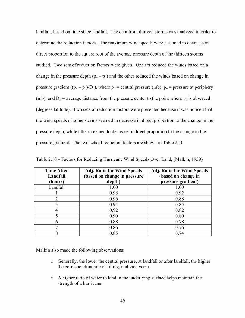
landfall, based on time since landfall. The data from thirteen storms was analyzed in order to
determine the reduction factors. The maximum wind speeds were assumed to decrease in
direct proportion to the square root of the average pressure depth of the thirteen storms
studied. Two sets of reduction factors were given. One set reduced the winds based on a
change in the pressure depth (pn – po) and the other reduced the winds based on change in
pressure gradient ((pn – po)/Dn), where po = central pressure (mb), pn = pressure at periphery
(mb), and Dn = average distance from the pressure center to the point where pn is observed
(degrees latitude). Two sets of reduction factors were presented because it was noticed that
the wind speeds of some storms seemed to decrease in direct proportion to the change in the
pressure depth, while others seemed to decrease in direct proportion to the change in the
pressure gradient. The two sets of reduction factors are shown in Table 2.10
Table 2.10 – Factors for Reducing Hurricane Wind Speeds Over Land, (Malkin, 1959)
Time After Landfall (hours)
Adj. Ratio for Wind Speeds (based on change in pressure
depth)
Adj. Ratio for Wind Speeds (based on change in pressure gradient)
Landfall 1.00 1.00 1 0.98 0.92 2 0.96 0.88 3 0.94 0.85 4 0.92 0.82 5 0.90 0.80 6 0.88 0.78 7 0.86 0.76 8 0.85 0.74
Malkin also made the following observations:
o Generally, the lower the central pressure, at landfall or after landfall, the higher the corresponding rate of filling, and vice versa.
o A higher ratio of water to land in the underlying surface helps maintain the strength of a hurricane.
49

The reduction of the peak gust wind speeds of a hurricane after landfall for three
hurricane events since Malkin’s study was given in Goldman, et al. (1974). The results of
Goldman’s research, along with a comparison to Malkin’s work are shown in Figures 2.8,
2.9, and 2.10.
Figure 2.8 – Reduction of Wind Speeds of Hurricane Carla, reproduced from Goldman, et al. (1974)
50

Figure 2.9 – Reduction of Wind Speeds of Hurricane Camille, reproduced from Goldman, et al. (1974)
51

Figure 2.10 – Reduction of Wind Speeds for Hurricane Celia, reproduced from Goldman, et al. (1974)
In summary, Goldman’s research determined the reduction factor for the peak gust
wind speed of a hurricane event after landfall to be approximately 0.90, 0.80, and 0.70 for
52

locations 50, 100, and 150 km inland, respectively. As shown in Figures 2.8, 2.9, and 2.10,
the values for the reduction factors agree somewhat with Malkin’s reduction factors. It is
pointed out, however, that there are large local differences, which are not accounted for by
Malkin’s factor, and which should be accounted for in the future. Goldman also pointed out
that the wind speed in Hurricane Celia, which struck Corpus Christi Bay, actually increased
once the hurricane made landfall. This is assumed to have occurred due to the added time
over water because the hurricane entered the coastline at the bay, along with the impact the
warm, shallow water had on feeding the hurricane.
Schwerdt, et al. (1979) also addressed the filling of a hurricane once it makes landfall.
The researchers broke the United States into three separate regions and developed a different
formula for decreasing the sustained wind speeds due to filling as a hurricane moves inland.
For the Gulf Coast region (Region A), the following equation was given for calculating the
reduction factor of the hurricane wind speeds. Note that the formula depends on the time
since landfall only, and does not account for the size of the hurricane or the forward speed of
the hurricane.
)00013.035.( 2tt
C
I eWW +−=
where W = overland wind speed at some specified time after landfall (friction effects not
considered); W = the overwater wind speed at landfall; and t = time, in hours. A graph of
the results of this formula is shown in Figure 2.11. It is important to note that this equation
does not address the effect of surface friction on the filling of hurricane winds. Also, the
reduction factor presented was for sustained winds, not peak gust wind speeds, as was the
case in Malkin (1959).
I
C
53

0.1
0.2
0.3
0.4
0.5
0.6
0.7
0.8
0.9
10 5 10 15 20 25 30
Hours After Landfall
Adj
ustm
ent F
acto
r
Figure 2.11 – Adjustment Factor of Hurricane Wind Speeds for the Gulf Coast region vs. Time Since Landfall, reproduced from Schwerdt, et al. (1979)
Another publication that addressed the filling rate of hurricane winds is Batts, et al.
(1980). When determining the rate of decay of a hurricane once it makes landfall, the
researchers assumed the decay of the hurricane was a function of the decrease in the
difference between the pressure at the center and the outer edge of the hurricane. (i.e., the
difference between the pressure at the outer edge of the storm and at the center of the storm
decreases once the storm makes landfall). The relationship was assumed to be:
tptp ]sin1[02.0)( max φ+−∆=∆
where t = travel time in hours (t at landfall = 0); )(tp∆ and maxp∆ in inches of Hg; and φ =
angle between the track of the hurricane and the coast (from 0 to 180 degrees).
Also noted in Batts, et al. (1980) was the fact that the wind speeds associated with a
hurricane are reduced at landfall due to the increased friction of the surface of the land as
54

compared to the open ocean exposure. Batts referenced the following sources that discuss
this topic:
o (Revised Standard Project Hurricane Criteria for the Atlantic and Gulf Coasts of the United States, Memorandum HUR 7-120, U.S. Department of Commerce, NOAA, June, 1972) estimated a value of 0.78 for reducing overwater hurricane strength wind speeds to overland wind speeds.
o (Bietry, J., Sacree, C., and Simiu, E., “Mean Wind Profiles and Change of Terrain
Rougness,” Journal of the Structural Division, ASCE, Vol. 104, NO. ST10, Proc. Paper 14099, Oct., 1978, pp. 1585-1595) assumed the following relationship between the 10-minute mean wind speed of overland and overwater winds at a height of 10 meters:
o
w
l
zpV
V10ln*2.0
1)10()10(=
where the values of the reduction factor (p) and the roughness coefficient ( ) were assumed to be 0.83 and 0.005 m respectively, yielding a reduction factor of 0.79. Batts, et al. (1980) eventually selected a conservative value of 0.85 as the reduction factor between the 10-minute mean wind speed of overland and overwater (at a height of 10 m). This value was conservatively taken to be greater than the value obtained using the preceding equation, due to the fact that the similarity relationships used to formulate that equation were for geostrophic winds, which do not represent the winds in a hurricane.
oz
Batts, et al. (1980) also presented fastest-mile hurricane wind speeds at the coastline
and at 200 km (124 miles) inland corresponding to various Mean Recurrence Intervals
(MRIs). This is shown in Figures 2.12 (a) and (b). Linear interpolation is allowed for
locations between these points. The coastal locations corresponding to the mileposts are
shown in Figure 2.13. It was found that the results obtained using their decay model differed
from those obtained by Malkin (1959) by only approximately 2%. Also, it was found that
hurricanes decayed very slowly as they moved inland at milepost 650 (the New Orleans
area). It was suggested that this may be due to the large bodies of water near the coastline
and that future research needs to be performed on these types of locations.
55

(a)
(b)
Figure 2.12 (a) – Estimated Fastest-Mile Hurricane Wind Speeds Blowing From Any Direction at 10 m Above Ground in Open Terrain Near the Coastline and (b) – at 200 km Inland, reproduced from Batts, et al. (1980)
56

Figure 2.13 – Mileposts Designations Used by Batts, reproduced from Batts, et al. (1980)
Georgiou, et al. (1983) used significantly different models than Batts, et al. (1980) for
the central pressure difference and rate of decay. The rate of filling in Georgiou’s research
was assumed to be a function of a filling parameter ( ) that varies depending upon the
coastal region in which the structure is located. The filling parameter accounts for the
decrease in the central pressure difference and also accounts for the change in the wind
profile of the hurricane as it makes landfall and moves inland. The following formula is
Df
57

suggested for determining the filling rate of mean hourly hurricane winds in the coastal
region from New Orleans, LA to Apalachicola, FL (the Gulf Coast region):
2)(1
1
D
o
fdp
p
+=
∆∆
where Dp = central pressure difference, Dpo = central pressure difference at landfall, d =
distance traveled inland after landfall (km), and (filling parameter) = 150 for the Western
Gulf Coast (Tampico, Mexico to Houston, TX) and 350 for the Mid Gulf Coast (from New
Orleans, LA to Apalachicola, FL (no units). It should be noted that this model used distance
inland as the measurement of decay, instead of time since landfall, as is the case with many
other cited sources.
Df
The wind speeds corresponding to various mean recurrence intervals calculated using
the model presented in Georgiou, et al. (1983) were given for the entire Gulf Coast and part
of the Atlantic Coast. These results are shown in Figure 2.14 along with comparisons with
the results obtained by Batts, et al. (1980). Georgiou’s results match rather closely with Batts
results in the Atlantic Coast region as well as the Gulf Coast region from New Orleans to the
Florida peninsula. Batts results are approximately 10-15% less than Georgiou’s over the
Florida peninsula.
Georgiou et al. (1983) also noted that “An important observation concerning the
behavior of tropical cyclones making landfall is that, at least for the first 10 to 15 hours,
gradient wind speeds are substantially affected only by the change to the central pressure and
not by surface changes which serve mainly to decrease surface wind speeds.”
58

Figure 2.14 – Mean Hourly Hurricane Surface Wind Speeds for Various MRI, reproduced from Georgiou, et al. (1983)
Research by Ho, et al. (1987) also addressed the rate of fill of hurricanes, but did not
give a suggestion as to how the filling of hurricane winds affects the wind speed. This paper
divided the coastline of the United States into three regions; Region A (the Gulf Coast),
Region B (the Florida peninsula), and Region C (the Atlantic Coast) and gives a rate of fill,
which is based on the pressure deficit at landfall, for time since landfall. It is important to
note that the regions are similar to those used by Schwerdt, et al. (1979), but are not identical.
Only the findings for Region A (the Gulf Coast) will be discussed here, as this is the only
region covered by this thesis. The filling rate for Region A as the hurricane moves inland is
shown in Table 2.11 for various initial (land falling) central pressure deficits.
59

Table 2.11 – Pressure Deficit vs. Time After Landfall, from Ho, et al. (1987) Time After
Landfall (hrs)
Pressure Deficit (mb)
0 40 60 80 85 90 95 100 105 110 2 34 51 68 72 76 78 80 81 82 4 30 44 59 63 66 67 68 69 70 6 26 40 53 56 58 59 60 61 62 8 22 34 45 48 50 51 52 53 54 10 20 30 40 42 44 45 46 47 47 12 18 27 36 38 39 40 41 41 42 14 16 24 32 34 35 36 36 36 36 16 14 21 28 30 31 32 32 32 32 18 12 19 25 26 27 28 28 28 28
A new hurricane wind model and wind filling model was defined in Vickery and
Twisdale (1995b). The wind field model is based on work done by Shapiro (1983). Three
different wind filling models were used based on the region of the coast; Gulf Coast, Florida
peninsula, and Atlantic Coast subject to hurricanes. The filling model used takes into
account the fact that more intense hurricanes fill more rapidly than weak hurricanes. The
basic form of the model is:
)exp()( atptp o −×∆=∆
where is the central pressure difference at landfall; t is the time since landfall in hours
and the filling constant (a) is equal to:
op∆
ε+∆+= oo paaa 1
where and are filling rate constants that vary depending on the region of the country
and e is a normally distributed error term with a mean of zero. The variation of the filling
constant (a) versus the central pressure difference at landfall is shown in Figure 2.15. An
oa 1a
60

interesting thing to note is that, for the Gulf Coast region, the filling model best matched the
observed data if a two hour delay was incorporated into the model.
Figure 2.15 – Filling Constant vs. Central Pressure Difference at Landfall for the Gulf of Mexico region, reproduced from Vickery and Twisdale (1995)
Vickery and Twisdale’s results were compared to storm data and the results of other
wind field and filling models. Their results were found to be slightly conservative for the
Gulf Coast, while the Batts, et al. (1980) model was very conservative and that the
conservatism increased with distance inland. They noted that the design wind speed (50 year
MRI) appears to be influenced by hurricane events as far as 200 km (124 miles) inland using
61

the Batts model, while their model limits the influence of hurricanes on the design wind
speed to approximately 100 km (62 miles) inland.
Kaplan and DeMaria (1995) developed a model to calculate the maximum sustained
1-minute surface wind speed (MSSW) of a hurricane, based on distance inland, as it moves
inland,
CeVRVVtV tbob −−+= −α)()(
where, for the Gulf Coast region, V(t) = maximum sustained 1-minute surface wind speed
(MSSW, in knots1), V = background wind speed = 26.7 Kt, R = a reduction factor to account
for the rapid decrease in wind speed as soon as the hurricane makes landfall = 0.9, V =
maximum 1-minute sustained wind speed just before landfall, a = a decay constant = 0.095
h
b
o
-1, and C is a correction factor for distance inland, given by:
bDDmC
o
+= )][ln(
where, for the Gulf Coast region, m )(1 tttc o −= , )(1 tttdb o −= , c1 = 0.0109 kt*h-2, d1 =
0.0503 kt*h-2, to = 50 hours, and t = time since landfall (hours), D = distance inland (km), and
Do = 1 km.
Using this formula they examined different category hurricanes, moving at different
speeds, and determined an envelope of the maximum wind speeds along the coast due to the
given storm. The results were then plotted on a map of the coastal United States, an example
of which is shown in Figure 2.16. The wind speeds shown are the maximum 1-min surface
winds (in knots).
1 Abbreviated as Kt. 1 Kt = 1 nautical mile/hour = 1.15 mph = .514 m/s
62

Figure 2.16 – Maximum 1-Minute Hurricane Surface Winds (knots) vs. Distance Inland (for a Hurricane with a Maximum Sustained Wind Speed of 90 knots and a Forward Speed of 8 knots), reproduced from Kaplan and DeMaria (1995) 2.5 Windborne Debris
Debris impact is a very important design consideration for any structure that is
designed to resist a hurricane event. Many types of objects, including gravel, 2” x 4”
wooden members, and sheets of plywood can be picked up and carried by hurricane-force
winds. The consequences of impact of these types of objects to the building envelope can be
quite extreme. If a building envelope component is not designed to resist the penetration of
windborne debris, the debris and/or the building component(s) that are carried with it, can
severely injure anyone inside the building. It is also possible for debris penetration to lead to
a complete collapse of a structure. If the building envelope on the windward face of a
structure is breached, positive internal pressurization will result, which increases the uplift on
the roof and the negative pressure on the leeward wall of the building. Also, a breach in the
63

building envelope allows wind and water to enter the structure, causing damage to the
building interior and contents. There are documented cases where the monetary damage to
contents due to wind and rain entering the building have exceeded the value of the structure,
while the building itself experienced little damage. This is often the case for an office
building that has a large number of its windows broken by flying roof gravel.
2.5.1 Windborne Debris and Flight Characteristics
The debris generated by high-wind events can be classified into three primary
categories: (1) Lightweight – roof gravel, etc; (2) Medium weight – timber plank, etc; and (3)
Heavyweight – utility poles, automobiles, etc (McDonald and Bailey, 1985). The most
important missile parameters relative to impact of a building component are the types of
missiles anticipated, the speed of the missile, and the length the missile travels. There has
been a great deal of research performed to determine the flight characteristics of windborne
debris. Much of this research has focused on windborne debris generated by tornados, but
there has recently been more research performed on windborne debris generated by
hurricanes. Research was performed by Lee and Wills (2002) on three different types of
objects (compact objects representative of roof gravel, rod-like objects representative of 2” x
4” timber planks, and sheet materials representative of plywood sheeting) in order to
determine their theoretical flight characteristics in hurricane events. Their findings are
shown in the following Tables. Also, Lee and Wills (2002) determined the minimum wind
speed at which an 8’ long 2” x 4” wooden member would be lifted off of the ground to be
approximately 70 mph. It was not clear what the averaging time of the wind speed discussed
in both of these papers was. A paper by Wills, et al. (2002) also has information on the flight
characteristics of wind borne debris. Table 2.12 gives the formulas given by Wills, et al.
(2002) for the threshold of flight for various shaped objects. Table 2.13 gives the wind speed
64

at which a compact object (such as roof gravel) would be picked up in a wind speed (Will, et
al., 2002).
Table 2.12 – Threshold of Flight for Various Shaped Objects, from Wills, et al. (2002)
Type of Object Threshold of Flight (U2)
Compact (roof gravel) glCIU Fam *)/)(/(22 ρρ=
Rod-Like (2” x 4” wooden members) gdCIU Fam *)/)(/(2/2 ρρπ=
Sheet Materials (Plywood Sheeting) gtCIU Fam *)/)(/(22 ρρ=
where: rm = material density; ra = air density; I = fixity parameter based on attachment of
the object (an object resting on the ground has I = 1.0); CF = force coefficient of the object; l
= typical dimension of the object; d = equivalent diameter; t = thickness; g = acceleration of
gravity
Table 2.13 –Diameter of Compact Objects (roof gravel) Transported for a Given Wind Speed, reproduced from Wills, et al. (2002)
Wind Speed (m/s) Material Size (mm)
10 Wood 12
10 Stone 2
20 Wood 50
20 Stone 9
40 Wood 200
40 Stone 37
65

Holmes (2001) made the following suggestions concerning distance traveled by
windborne debris:
Time (in seconds) taken to accelerate from 0 to : mv
+−= )1ln()1( kUT
kUTUD
where: )( m
m
vUkUv−
=T
where D is in meters; T is in seconds; = missile speed (m/s); U = wind speed (m/s); mv
)2/()( lCk mDa ρρ= (with units of 1/m); ra = density of air (kg/m3); CD = coefficient of drag
(no units); rm = density of object (kg/m3); l = length of object (meters)
Table 2.14 shows the time taken and the distance traveled for a steel ball and a timber
missile to reach a given speed for a wind speed of 32 m/s. In discussion with Holmes, it was
determined that the averaging time of the wind speed is not a peak gust wind speed, but
rather a sustained wind speed on the order of one to ten minutes.
Table 2.14 – Flight Times and Distance Traveled for Two Objects, reproduced from Holmes (2001)
Object/Final Speed Time Taken (seconds) Distance Traveled (m)
Steel Ball* to 20 m/s 5.4 71
Steel Ball* to 30 m/s 49 1270
Timber Piece* to 20 m/s 69 910
Timber Piece* to 30 m/s 625 16300
*Steel Ball – 8 mm diameter and 2 gram mass *Timber Piece – 50 mm x 100 mm cross section, 1.6 m long; and weighing 4 kg
66

One of the first recommendations made for the missile speed to use for testing
building envelope components against the effects of medium weight debris impact was by
Minor, et al. (1978). Minor suggested a 12’ long 2” x 4” wooden member traveling at ½ of
the design wind speed of the building be used for testing the impact resistance of building
envelope components. Wills, et al. (2001) and Lee and Wills (2002) made this same
suggestion.
2.5.2 Debris Impact Resistance
Much research has been performed on the impact resistance of materials most
commonly used in residential and commercial construction to determine the protection
afforded occupants of a building subjected to flying debris generated in a high-wind event.
These tests all entail firing various projectiles representative of the types of missiles common
in the debris field of a high wind event.
A large amount of research has been performed over the years of the most common
types of wall construction. Many researchers have tested the impact resistance of concrete
masonry walls (commonly referred to as CMU walls). McDonald and Bailey (1985);
McDonald (1990); McDonald (1992) used a compressed air cannon at Texas Tech University
to fire 2” x 4” missiles at different types of walls to test their debris impact resistance. Both
reinforced and unreinforced CMU walls as well as the typical residential wall type (wood
stud wall with brick veneer cladding) were tested to determine their debris impact resistance.
The stud wall results won’t be discussed herein because they are not commonly found in
commercial or industrial buildings, which is the focus of this thesis.
Hollow 8” unreinforced masonry walls were found to be perforated by 2” x 4”
wooden missiles traveling at only 65 mph. Also, the back of the 8” CMU broke into many
large pieces (some of them weighting as much as 2 lb), which could be a deadly threat to
67

people on the other side of the wall. This lead the researchers to the conclusion that
unreinforced masonry walls were not proficient at stopping the typical missile found in a
high wind event. When all of the cells of the 8” CMU were grouted and reinforced with #4
rebar the wall became essentially impervious to the effects of the missile. At test speeds of
up to 130 mph the missile was destroyed when it struck the wall, but the wall was not
damaged. Also, 12” CMU walls were tested, with results very similar to the 8” wall, leading
the researchers to make the following conclusions:
o All cells must be grouted and reinforced to stop the missile at high speeds. If the missile hits an unreinforced cell, the wall will be penetrated.
o The use of grout only will stop the missile, but the wall will experience a great deal of
cracking. o The use of horizontal reinforcement has no impact resistance benefit. o The shape of the nose of the missile had little effect. o A missile impacting the wall at 45o tends to glance off the wall without causing
damage.
Concrete panels were also tested by McDonald (1992) to determine their impact
resistance. It was found that an unreinforced 4” thick concrete wall panel is able to resist
penetration from a 15 lb 2”x4” wooden member traveling at speeds exceeding 130 mph, but
it will experience a great deal of cracking. Placing #4 rebar at 12” on center spacing each
direction prevented the cracking. The use of thicker wall panels and higher impact speeds
caused the missile to be destroyed.
Glazing is vulnerable to debris impact not only from large debris such as 2” x 4”
wooden missiles, but also to small missiles, such as roof gravel. Research has shown that the
three most common types of glass (annealed, heat strengthened, and fully tempered) are all
vulnerable to impact from small missiles (Minor, et al., 1978, Minor, 1994). The most
common type of small missile found in high-wind events is roof gravel with a weight of
68

between 0.5 g and 5.0 grams (Minor, 1994). There are many products available, including
laminated glass and various types of shutters systems, which increase the debris impact
resistance of glass openings.
2.5.3 Debris Impact Criteria of Various Codes and Standards
Debris impact resistance is an important consideration when designing for hurricanes.
There are a number of different codes and standards that have established criteria for building
envelope components to be deemed “debris impact resistant.”
• ASTM E 1886–97 and ASTM E 1996-01
ASTM E 1886–97 (ASTM, 1997) and its companion specification, ASTM E 1996-01
(ASTM, 2001) outline a procedure to determine the debris impact resistance and subsequent
cyclic pressure loading resistance of building envelope components. Depending upon the
installed height of the component above the ground and the Wind Zone classification of the
building, the components are subjected to small and/or large missile impacts followed by
cyclic pressure loading. The missiles used in the procedure are described below:
o Small Missile – “A solid steel ball having a mass of 2 g (0.004 lb) + 5 %, with an 8-mm (5/16-in.) nominal diameter, and an impact speed between 0.40 and 0.75 of the basic wind speed (3-s gust in accordance with ANSI/ASCE 7).”
o Large Missile – “A No. 2 or better Southern Yellow Pine or Douglas Fir 2 x 4 in.
lumber having an American Lumber Standard Committee accredited agency mark having a mass of between 2050 g + 100 g (4.5 + 0.25 lb) and 6800 g + 100 g (15.0 + 0.25 lb) and having a length between 1.2 m + 100mm (4 ft + 4 in.) and 4.0 m + 100 mm (13.2 ft + 4 in.) and an impact speed between 0.10 and 0.55 of the basic wind speed (3-s gust in accordance with ANSI/ASCE 7).”
Three separate test specimens are subjected to the missile impact test(s) and each are
impacted at different locations. If one of the test specimens fails, the component is rejected.
To be deemed acceptable, after the required testing, there must be no tears longer than 5” or
any openings that a 3” diameter sphere can pass.
69

o For all heights, components on a building located in Wind Zone 1 and Wind Zone 2 must withstand impact from a 9.0 lb, 8 ft. long wooden member with 2” x 4” nominal dimensions traveling at 50 ft/s.
o Components less than 30’ high on a building located in Wind Zone 3 must withstand
impact from a 9.0 lb, 8 ft. long wooden member with 2” x 4” nominal dimensions traveling at 80 ft/s.
o Components greater than 30’ high on a building located in Wind Zone 3 must
withstand impact from a 9.0 lb, 8 ft. long wooden member with 2” x 4” nominal dimensions traveling at 50 ft/s.
Wind Zone 1 is defined as a location having a basic wind speed between 110 mph and
120 mph; Wind Zone 2 is defined as a location having a basic wind speed between 120 mph
and 130 mph and located at distances greater than one mile from the coast; and Wind Zone 3
is defined as a location having a basic wind speed greater than 130 mph or a basic wind
speed greater than 120 mph and within one mile of the coast. If the components pass the
requirements of the small and/or large missile impact test, the performance of the building
envelope components must also be tested for cyclic static air pressure loading resistance after
completion of the missile impact test(s). The cyclic pressure loading sequence requires that
the impacted component be subjected to a series of pressure fluctuations and continue to
remain unbreached. The magnitude of the pressure the component is subjected to is
determined by the engineer based upon the pressure resistance needed for design. For an
“Essential Facility”, which includes hospitals with emergency treatment facilities, fire and
police stations, emergency shelters, and emergency response facilities, all building envelope
components must withstand impact from both large and small missiles.
• ASCE 2002
ASCE 7-02 (ASCE, 2002) requires that all components of the building envelope for a
structure located in “wind borne debris regions” that is not classified as being open during a
high wind event must be “Impact Resistant” or have an “Impact Resistant Covering”. It
70

requires that for a building envelope component to be defined as “Impact Resistant”, it must
pass the requirements of ASTM E 1886 - 97 and its companion Specification ASTM E 1996
- 01. The wind borne debris regions are defined as areas within hurricane prone regions
located: 1) in areas where the basic wind speed is 120 mph or greater or 2) within one mile of
the coastal mean high water line where the basic wind speed is 110 mph or greater and in
Hawaii.
• Texas Department of Insurance Standard TDI 1-98
TDI 1-98 (TDI, 1998) was produced in order to “minimize public and private losses
due to wind and windborne debris damage to impact protective systems and exterior opening
systems.” The test program consists of three identical specimens tested for large and/or
small missile impact resistance and cyclic pressure loading. For a component to be deemed
acceptable, at least two of the three specimens must pass the criteria of this standard.
Components other than impact protective systems with openings larger than 3/16” need not
be tested for the small missile impact resistance if they pass the large missile impact
resistance test.
In order for a building envelope component to be deemed to pass the large missile
impact test, it must withstand impact from a 7 ft. long Southern Pine or Douglas Fir-Larch
with nominal dimensions of 2” x 4” and weighing between 9 and 9.5 lbs traveling at
approximately 50 ft/s (34 mph). In order for a building envelope component to be deemed to
pass the small missile impact test, it must withstand impact from 10 spherical steel balls each
weighing 2 grams traveling at approximately 130 ft/s (89 mph). Components are also
required to pass a cyclic wind pressure loading sequence after passing the debris impact test.
The missile impact tests and cyclic pressure tests are different if the building
envelope component is defined as an impact protective system or an exterior opening system.
71

Impact protective systems are defined as components that are placed over the exterior
opening system, either temporarily or permanently. Examples include shutters, plywood, etc.
Exterior opening systems are defined as systems that may be breached in a high wind event,
such as doors, windows, etc.
• Florida Building Code 2001
The Florida Building Code (SBCCI, 2001) requires that all building envelope
components located up to and including 30’ above the ground are required to pass the large
missile impact test, in which the specimen is impacted with a 9 lb. wooden member having
nominal dimensions of 2” x 4” traveling at 50 ft/s. Building envelope components located at
heights greater than 30’ above the ground are required to pass the small missile impact test,
in which the specimen is impacted with 10 solid steel balls, each weighing 2 grams, traveling
at 130 ft/s. Glazing components that pass the missile impact test(s) are also required to pass
a cyclic wind pressure loading test to be deemed acceptable.
• FEMA 361 – Design and Construction Guidance for Community Shelters
FEMA 361 (FEMA, 2000a) is intended to be used for the design of community
shelters in high wind events. It is intended primarily for the design of tornado shelters. The
wind speed used for the design of buildings in FEMA 361 is considered to be an ultimate
wind speed, therefore the debris impact requirements must also be for an ultimate event. All
building envelope components must be able to withstand being breached by a 12’ long, 15 lb.
wooden member with nominal dimensions of 2” x 4”, traveling 100 mph for missiles
traveling horizontally and 67 mph for missiles traveling vertically.
• Standard for the Design, Construction, and Performance of Storm Shelters The publication entitled “Standard for the Design, Construction, and Performance of
Storm Shelters” (NSSA, 2001) was produced by the National Storm Shelter Association
72

(NSSA) and is intended to be a further developed into “A Storm Shelter Industry Standard.”
The standard uses ultimate wind speeds and references FEMA 361 (FEMA, 2000a) for debris
impact requirements.
• National Performance Criteria for Tornado Shelters
The publication entitled “National Performance Criteria for Tornado Shelters”
(FEMA, 1999b) was produced by FEMA to give designers a set of guidelines to follow when
designing tornado shelters. The standard uses ultimate wind speeds and references FEMA
361 debris impact requirements.
• Guidelines for Design and Evaluation of Department of Energy Facilities Subjected to Natural Hazard Phenomenon The Department of Energy (DOE) of the United States has issued publication
containing a set of criteria on debris impact requirements that must be met for any energy
facility. The publication is called “Guidelines for Design and Evaluation of Department of
Energy Facilities Subjected to Natural Hazard Phenomenon” (UCLR 15910.) Two different
sets of criteria are given depending upon the relative importance of the building. Also, the
requirements are different for buildings subject to tornadic winds. The recommendations
given by UCRL 15910 are shown in Table 2.15. A High Hazard Facility is defined as a
facility in which a failure would result in life threatening consequences to the public
surrounding the site. A failure of a Moderate Hazard Facility would result in life threatening
consequences to workers surrounding the facility. For comparison purposes, a failure of a
Low Hazard Facility would result in life threatening consequences to workers in the local
area of the facility.
73

Table 2.15 – Debris Impact Test Criteria for Department of Energy Critical Facilities, from McDonald (1992) Moderate Hazard Facility High Hazard Facility
Straight Winds 15 lb 2x4 timber plank
@ 50 mph (horiz) max height 30 ft
15 lb 2x4 timber plank @ 50 mph (horiz) max height 50 ft
Tornadoes
15 lb 2x4 timber plank @ 100 mph (horiz), 70 mph (vert)
max height 50 ft
75 lb 3” dia. steel pipe @ 50 mph (horiz), 35 mph (vert)
max height 75 ft
15 lb 2x4 plank @ 150 mph (horiz), 100 mph (vert)
max height 200 ft
75 lb 3” dia. steel pipe @ 75 mph (horiz), 50 mph (vert)
max height 100 ft
3000 lb automobile @ 25 mph rolls and tumbles
2.6 Rainfall and Rain Load
2.6.1 Rainfall Rate
The current rate of rainfall used by many building codes for the design of a building
is the 1-hour, 100-year Mean Recurrence Interval (MRI) rainfall rate. This is the rate of rain
that falls in one hour that has a 1/100 chance of being exceeded each year. This rainfall rate
was determined using rainfall associated with extratropical rain events. Research into
rainfall rates of past tropical events and extratropical events appears to indicate that design
rainfall rates associated with hurricane events has not been proven to be statistically different
from that of extratropical events (Schoner and Molansky, 1956; Hershfield, 1961; NOAA,
1977; Grymes, 2002; and Faiers, et al., 1997).
2.6.2 Rain Load
The most common method of calculating rain load on the roof of a building is the
method given in ASCE 7-02. The ASCE 7-02 method of determining the Rain Load is
outlined in the following equation:
74

R = 5.2(ds + dh)
where:
o R = rain load on the undeflected roof, in lb/ft2. The phrase “undeflected roof” means that the deflections from loads (including dead load) are not considered when determining the amount of rain on the roof. i.e., this load does not take into account the effects of ponding. The structure must be designed such that ponding does not occur.
o ds = depth of water on the undeflected roof up to the inlet of the secondary drainage
system when the primary drainage system is blocked (i.e., the static head), in inches. The static head is simply the distance to the secondary drainage system. For example, if the secondary drains are 2” from the roof surface, ds = 2”.
o dh = additional depth of water on the undeflected roof above the inlet of the secondary
drainage system at its design flow (i.e., the hydraulic head), in inches. The hydraulic head is a function of a number of factors; the rainfall intensity used for design, the area of roof each drain is assumed to empty, and the type and area of the drainage system used. For example, for a given size drain, the hydraulic head will increase as the rainfall intensity and/or the area the drain empties increases.
2.7 State of the Practice of Hurricane Shelter Design and Assessment
2.7.1 Design of Hurricane Shelters
There are relatively few codes or standards that address the planning and design of
facilities to be used as shelters during high wind events. Two such publications were
produced by the Federal Emergency Management Agency (FEMA) and are entitled “Taking
Shelter From the Storm: Building a Safe Room Inside Your House,” also known as FEMA
320 (FEMA, 1999c) and “Design and Construction Guidance for Community Shelters,” also
known as FEMA 361 (FEMA, 2000a). As the names suggest, FEMA 320 provides a set of
guidelines for the design of small shelters to be constructed within a single-family residence,
while FEMA 361 provides a set of guidelines for the design of a community shelter to be
used to protect a large number of people. Although both of these publications address
hurricane and tornado events, the main focus is the design of tornado shelters. Some of the
75

important guidelines and recommendations given by these publications are given in the
following paragraphs.
• Wind Speed
The design wind speed used in both publications is selected to provide the occupants
of the shelter “near-absolute protection from death and injury.” This means that no matter
the magnitude of the wind event, the occupants of the shelter are deemed to be safe. This
gives individuals a place to go for any wind event, but results in a very expensive design.
The wind speed used for design by both publications, though applicable to hurricane wind
events, is controlled primarily by the wind speeds generated by tornadoes. This level of
protection is mandated for a tornado shelter because the wind speed associated with a tornado
can change very rapidly, and if someone is going to seek shelter in the structure, it is
imperative that the structure remains standing if the tornado intensifies. See Figure 2.17 for
the design wind speed used by these publications. For a hurricane shelter, however, the wind
speed to be anticipated at the shelter location for a given hurricane event can be predicted
ahead of time. This enables the designer to design a structure for any given hurricane
intensity. When a hurricane is approaching, a decision can be made as to the suitability of a
structure to be used as a hurricane shelter based on the hurricane intensity used during the
design process.
• Debris Impact
Along with being able to withstand the high winds associated with an extreme wind
event, all components of a structure also have to be able to resist penetration by flying debris.
For a residential shelter, this is the case that will most likely control the design of the shelter
due to the small wall area. For a community shelter, however, the large wall areas cause
higher wind pressures, which usually controls design. For large and small shelters, the loads
76

Figure 2.17 – Wind Speed Map Used in FEMA 361 and FEMA 320, from FEMA (1999c)
produced by both the design wind speed and the debris impact loading must be investigated
and designed and the structure designed accordingly. FEMA gives the following criteria for
debris impact resistance:
o The test member must be able to withstand the impact from a 15-lb wood 2”x4” (nominal) member, typically 12’ long, traveling at 100 mph for horizontally traveling missiles and 67 mph for vertically traveling missiles and striking the test specimen at a 90o angle.
o All components of the shelter (walls, roof, doors, windows, etc.) must be able to
withstand the above criteria. Several recommendations are given as to the best way to ensure that each component is sufficient.
77

• Additional Considerations
Along with the design wind speed and debris impact, there are a number of other
considerations that must be taken into account. Some of these include:
o Is the shelter in an area that is susceptible to flooding? If so, the shelter must be
designed accordingly. If possible, the shelter should be moved outside of the
flood area.
o Is the shelter in a seismically active area? If so, the building must be designed
accordingly.
• Human Factors
It is important that due consideration is given to the fact that individuals will be
sheltering inside the facility during a high wind event. FEMA 320 (FEMA, 1999c), suggests
that a minimum of 10 ft2 per person be provided in a residential shelter. FEMA 361 (FEMA,
2000a) suggests that 20 ft2 per person be provided for a length of stay of only a few days, but
if the length of stay is anticipated to be longer, that 40 ft2 per person be provided in a
community shelter. Also, the local building code should be checked to ensure that all of its
requirements are met.
In 1999, as part of the state of Florida Statewide Emergency Shelter Plan, the state of
Florida produced a set of design criteria that were required to be met when designing an
educational facility entitled “Public Shelter Design Criteria” (Florida Dept. of Education,
1999). The purpose of the guidelines was to decrease the shelter deficit of the state by
designing all educational facilities that were being built such that they could be used as
shelters in the event of a hurricane event. Some of the recommendations of the publication
are given in the following bullet list:
78

o The entire structure is to be designed using ASCE 7-93 (ASCE, 1993) as a minimum.
o It was suggested that the portion of the structure to be used as a shelter be
designed using a wind speed of 40 mph greater than that given by ASCE 7-93, with an Importance Factor (I) of 1.0.
o All building envelope components were required to resist penetration from flying
debris.
In 2002, Lee County, Florida produced their own set of hurricane shelter guidelines,
entitled “Lee County Emergency Shelter Guidelines and Criteria” (Lee County, FL, 2002).
Relevant structural design considerations of this publication are:
o ASCE 7 procedures are to be used with a design wind speed of 150 mph peak gust.
o Importance Factor (I) of 1.0 is to be used for design.
In 2001, the state of Florida also produced a new building code (SBCCI, 2001) with
assistance from the SBCCI that was intended to improve the performance of structures that
are subjected to hurricane strikes. Different guidelines were given depending on location
from the coast and many other considerations. This was also done by the state of Texas. In
1998, Texas adopted the “Building Code for Windstorm Resistant Construction” (TDI,
1998). Two sets of guidelines were given depending on if the structure was located inward
or seaward of an imaginary line dividing the hurricane coastal area an inland areas.
2.7.2 Assessment of Hurricane Shelters
In October of 1997 the state of Louisiana, with help from the University of Florida
School of Building Construction, released a document entitled “Hurricane
Evacuation Shelter Selection Guidelines,” (LOEP, 1997) the purpose of which was to aid in
the selection of existing facilities to be used as hurricane shelters. Fifteen different building
planning and design issues are considered. A least risk decision making process is then used
79

80
to determine the suitability of using the building as a hurricane evacuation shelter. The
fifteen building facets to be considered are:
o Storm Surge Inundation o Rainfall Flooding / Dam Considerations o Hazardous Materials and Nuclear Power Plant Consideration o Lay-Down Hazard Exposure o Wind and Debris Exposure o Wind Design Verification o Construction Type / Loadpath Verification o Building Condition o Exterior Wall Construction o Fenestrations and Window Protection o Roof Construction / Roof Slope o Roof Open Span o Roof Drainage / Ponding o Interior Safe Space o Life Safety / Emergency Power
Each of the previously mentioned building facets are investigated and categorized
in one of three different categories: Preferred, Acceptable, or Marginal. Based upon the
overall results from the least risk decision making process, it is then determined if the
building is able to be used “As Is”, if the building can be used with some modifications, or if
the building is not suitable for use.
Another publication that addresses the selection of viable hurricane shelters is
“Standards for Hurricane Evacuation Shelter Selection,” (ARC, 2002) which is produced by
the American Red Cross. This publication gives guidelines on the following topics:
o Surge Inundation o Rainfall Flooding o High Winds o Hazardous Materials o Interior Building Safety Criteria During Hurricane Conditions
A least risk decision making process is then used to determine the suitability of the
building for use as a hurricane shelter based on how well the building meets the previously
mentioned topics.

CHAPTER 3: FORMULATION OF DESIGN GUIDELINES 3.1 Introduction
Historically, buildings, including facilities designated as essential in a hurricane
event, have been designed using a probabilistic approach. Buildings designed using this
approach have a certain probability against failure when subjected to the anticipated loads.
The acceptable probability of failure is based on a great deal of research along with input
from the general public on the acceptable probability of structural collapse. For buildings
located in hurricane prone regions, the wind speed used for design is the wind speed
corresponding to a 500 year Mean Recurrence Interval (MRI) divided by a factor of 1.225.
For a facility designated as essential, the wind speed is increased by an Importance Factor of
1.15 to increase the MRI. After all of the anticipated loads have been determined, the loads
are combined in the appropriate load combinations to get the overall loads on each
component of the structure. Once the loads to be used for design have been determined, all
components of the building are designed. Currently, almost all building codes are based on a
prescriptive design approach, which results in a “no damage” design when the facility is
subjected to the design event (Harris, 2002 and Hamburger, 2002).
Another option available for designing facilities designated as essential in a hurricane
event is to use a publication produced by the Federal Emergency Management Agency
(FEMA) entitled Design and Construction Guidance for Community Shelters, otherwise
known as FEMA 361. The wind speed presented in this publication is an “extreme” wind
speed with a very small chance of ever being exceeded, i.e., a very long MRI, on the order of
2,000 to 10,000 years, depending on location. This gives shelter inhabitants “near absolute”
protection from any wind event, but results in a very expensive building. There are also
other publications that address the design of hurricane shelters (FEMA, 2000c; FEMA,
81

1999c; FEMA and Texas Tech, 1999; NSSA, 2001). All of these publications, however,
produce an “ultimate event” design as well.
There have recently been guidelines produced outlining procedures to be used when
designing hurricane shelters in the state of Florida. In 1999, the state began requiring that
any new educational facilities have an area designated to be used as a hurricane shelter. It
was highly recommended by the 1999 “State Requirements for Educational Facilities”
(Florida Department of Education, 1999) that the wind speed used for design of these
facilities be the wind speed from the ASCE 7 map plus 40 mph. Recently, Lee County in
Florida produced a hurricane shelter design guideline (Lee County, 2002) specifying a design
wind speed of 150 mph peak gust for hurricane shelters.
This thesis proposes a totally different approach for the design of facilities designated
as essential during a hurricane event. When designing a new essential facility, the building
owner can select the hurricane strength to be used as the design event for a given facility
based on the shelter demand, the available budget, and any other relevant considerations.
The associated loads for the design hurricane event can then be determined and the building
designed accordingly. Then, when a hurricane is approaching, the building owner will have
a much clearer understanding of the strength of the building relative to the strength of the
approaching hurricane, and manage the emergency preparedness operations accordingly.
For a given hurricane approaching the coast, the approximate wind speed is known.
The MRI of the wind speed associated with the approaching hurricane is of little concern to
emergency managers. The hurricane is coming and the probability associated with the winds
of that hurricane event does not matter. The only thing that matters is that the building
performs up to the desired design objective when exposed to the hurricane about to strike.
82

Since there are several types of essential facilities, which are required to perform
different functions before, during, and after a hurricane event, all facilities designated as
essential need not perform to the same level for a given hurricane event. For example, a
building used to store equipment for emergencies during the hurricane does not need to
perform to the same level as a hospital that is required to be fully operational during and after
the hurricane event. In order to produce the most economical design for each of the building
use classifications, a different design approach from the “no damage” approach used by most
building codes is required. A performance-based design approach is proposed for facilities
designated as essential during a hurricane event. Each type of essential facility is assigned a
required performance level, and the building is then designed to meet these performance
requirements.
This type of approach allows for the most efficient building design. The use of the
building before, during, and after the hurricane, as well as the building owner’s desired
design hurricane event, can be taken into account in the planning and design of the structure.
Also, the performance-based design approach allows for the use of the latest products in the
design of the building. These two aspects of the performance-based design approach make it
ideal for the design of essential facilities because it allows for the best, most cutting-edge,
and most efficient structural design. This thesis will provide structural engineers and
architects a document to use as a reference when building a structure designated as an
essential facility during a hurricane event using the previously-mentioned design philosophy.
3.2 Performance Criteria for Essential Facilities
3.2.1 Types of Essential Facilities
Five different categories of essential facilities have been identified for use during
hurricane events, as shown in Table 3.1. The facility categories were decided upon based on
83

the use of the facility during and after the hurricane event and the corresponding relative
performance level required by the facility. The five facility categories and the associated
buildings in each category were determined by first reviewing existing Performance-based
Design standards (SEAOC, 1995; FEMA, 2000b; ICC, 2001), which were discussed in
Section 2.2 of this thesis. Next, the recommendations made by these standards were
modified to reflect the special use requirements of facilities utilized during hurricane events.
The determinations made were then reviewed by experts in the field of emergency
management operations (Sean Fontenot – Assistant Division Chief of the Louisiana Office of
Emergency Preparedness (LOEP) and Dr. Walter Maestri, III – Director of the Jefferson
Parish OEP). It is important to recognize that, in most instances, the use of the building
during and after the hurricane event is a secondary function of the facility.
Table 3.1 – Essential Facility Classifications
Essential Facility Classification
Description
Function Critical Facilities Facilities that must remain operational before, during, and after the hurricane event. Examples include emergency operations centers and certain hospitals.
Base of Operations for Response
Buildings that house emergency response functions needed in the immediate wake of the hurricane, but do not necessarily need to remain fully operational at the height of the storm. A fire station would generally fit in this category.
Hurricane Shelter Intended to provide a safe place to go during the hurricane and a place to stay for some length of time after the storm has passed.
Refuge of Last Resort
Intended for people who did/could not evacuate or travel to a shelter, but do not wish to remain in their homes. It may or may not be safer than their homes. There is no minimum implied level of safety as there is in a shelter.
Emergency Equipment/Supplies
Storage Facility
A facility used to house equipment and supplies needed for emergency response and recovery beginning immediately after the storm event. Different from the other four building categories above, it is not intended to be occupied during the hurricane, but individuals will be going inside after the hurricane in order to retrieve the stored materials.
84

3.2.2 Development of Performance Criteria
For each Essential Facility Classification, the allowed level of damage to the various
components of the building for the design event of the building must be determined. The
building systems investigated and the damage levels considered are shown in Table 3.2.
Also shown in Table 3.2 are the graduations in the various levels of danger to life safety of
people inside one of the facilities. The building systems suggested by existing Performance-
based Design standards (SEAOC, 1995; FEMA, 2000b; ICC, 2001) were reviewed and
modified to account for the special needs of facilities utilized during hurricane events. The
Primary Structural System is defined as girders, load bearing walls, wind bracing, and
columns. Not included in the Primary Structural System are secondary structural elements,
such as roof joists, girts, etc. These are considered part of the roof and wall systems. The
Building Envelope consists of the roof cladding, glazed openings, doors, wall cladding, roof
joists, girts, etc. It should be noted that the performance of the building envelope has a direct
impact on the damage to the interior of the building. The building envelope was broken into
two different systems; Windows/Doors and Roof and Wall Systems. The damage levels and
the definitions associated with each damage level were determined by reviewing existing
Performance-based Design standards and modifying them as appropriate for hurricane
facilities.
3.2.3 Performance Criteria Survey
A survey was given to members of the emergency management community to
determine appropriate levels of building damage and danger to occupants for a building in
each of the five essential facility classifications. The survey was developed by first giving a
trial version to peers of the author. Feedback was received and a final version was created.
A description of the final layout of the survey follows (the complete survey is given in
85

Table 3.2 – Definition of Damage Levels for Various Building Systems/Components
System Damage Levels Severe – Injuries to building occupants may be high in numbers and significant in nature. Significant risk to life may exist. There is a high likelihood of single life loss and a moderate likelihood of multiple life loss. High – Injuries to building occupants may be locally significant with a high risk to life, but are generally moderate in numbers and nature. There is a moderate likelihood of single life loss, with a low probability of multiple life loss. Moderate – Injuries to building occupants may be locally significant, but generally moderate in numbers and in nature. There is a low likelihood of single life loss, very low likelihood of multiple life loss.
Overall Danger to Life Safety
Mild – Injuries to building occupants are minimal in numbers and minor in nature. There is a very low likelihood of single- or multiple life loss. Severe – Building is near collapse. Little residual strength or stiffness left in the structure. Rehabilitation to achieve pre-storm load-carrying capability likely to be impossible or impractical for economic or other reasons. The building is likely a complete loss. Moderate – Some residual strength and stiffness left in the structure. Rehabilitation to achieve pre-storm load-carrying capability likely to be very costly. Light – Structure retains most of its pre-storm strength and stiffness. Little rehabilitation needed to achieve pre-storm load-carrying capacity.
Primary Structural
System Damage
None to Very Light – Little to no damage to the structural components. Structure possesses pre-storm load-carrying capacity with very little or no rehabilitation. Severe - Most of the windows and doors are completely destroyed. Many door openings blocked or impassable. Replacement of many opening components required. Building interior experiences significant damage in areas adjacent to failed exterior. Moderate - Significant damage to some opening components. Many doors and windows are breached. Some opening components are able to be repaired, while many must be replaced. Most door openings free of obstructions. Some damage to the building interior due to wind and water entering through the failed opening. Light - Opening components experience little damage. Openings able to be returned to their pre-hurricane functionality with minor repair or replacement. Very little damage to the building interior.
Building Envelope Damage:
Windows/ Doors
None to Very Light - Little or no damage to any of the opening components. The damage which does occur has no effect on use of building and repair of the opening components does not interfere with the use of the building. Damage to the opening components is mainly cosmetic in nature. No damage to the building interior.
(table cont.)
86

Severe - Most cladding/ roofing components either removed or completely destroyed. Repair likely to be impractical for economic or other reasons. Replacement probably needed. Large holes likely in the roof and/or walls. Major wind and water penetration of structure, causing a great deal of damage to the interior and contents. Moderate - Small cladding/roofing elements removed or destroyed. Many of the larger elements retain most of their functionality, but may be damaged beyond repair. Large holes possible and small holes likely in the roof and/or walls. Some damage to the building interior due to wind and water entering the structure. Light - Roofing/cladding components remain functional, but some components must be replaced in order for building envelope to function the same as it did before the storm. Small holes possible in the roof and/or walls, allowing water to leak into the building. Very little damage to the building interior.
Building Envelope Damage: Roof and
Wall Systems
None to Very Light - Almost no damage to the roofing/cladding components. Functionality of the roofing/cladding components remains the same after the event as it was before the event with little or no repair or replacement. No damage to the building interior. Severe - Many to most of the components are out of order and some damaged beyond repair and require replacement. Moderate - A small percentage of the components are in working order. Primary lighting likely to be non-operational. Emergency lighting is in working order during and after the event. Replacement or repair of some components required. Very Light – No significant damage. Components not necessarily operational during the event, but are ready to be reactivated immediately after the storm. Emergency lighting in working order during and after the event.
Mechanical and
Plumbing Systems Damage:
Electrical/ Lighting Systems
None - All components remain fully operational during and after the event. Severe - Many to most of the components are out of order and some damaged beyond repair and require replacement. Some components may be lost due to wind. Moderate - A small percentage of the HVAC system is in working order. Replacement or repair of some components required. Very Light – No significant damage. Components not necessarily operational during the event, but are ready to be reactivated immediately after the storm.
Mechanical and
Plumbing Systems Damage: HVAC
Equipment None - All components remain fully operational during and after the event. Severe - Many to most of the components are out of order and some damaged beyond repair and require replacement. Moderate - A small percentage of the plumbing system is in working order. Replacement or repair of some components required. Very Light – No significant damage. Components not necessarily operational during the event, but are ready to be reactivated immediately after the storm.
Mechanical and
Plumbing Systems Damage:
Plumbing Systems None - All components remain fully operational during and after the event.
87

Appendix A). The first page of the survey described the five different facility categories.
The second page was intended to obtain information about the people filling out the survey.
It included a section for the survey participant to give his/her profession, experience with
sheltering, and Parish/City. Each of the next seven pages was devoted to the seven topics to
be decided upon (six building systems and overall life safety). Definitions were given for
building components considered to be a part of the primary structural system and the building
envelope. The various damage levels for each system were given along with a table for the
survey participant to select what he/she believes to be the appropriate damage level for each
of the five facility classifications. Also provided on each sheet was a place for any additional
notes that the survey participant felt a desire to provide.
The survey was given to two different sets of individuals. The survey was first given
to a group of people who attended a Shelter Assessment Training Workshop in St. Tammany
Parish that was given by Dr. Marc Levitan of the LSU Hurricane Center on June 27, 2002.
Twelve individuals took part in the survey. Most of the respondents were from the
emergency management community, but many had little or no experience with sheltering.
There were also four people from the engineering and architecture community, as well as a
building official. The survey was given out again on July 2, 2002 to twenty-four individuals
that attended the Southeastern Louisiana Hurricane Task Force meeting at Lafreniere Park in
Metairie. Again, almost all of the survey participants were employed in emergency
management, but the respondents of this survey had much more experience in shelter
management and selection. Also taking part in the survey were a police officer, two people
in the medical profession, and two Red Cross workers. In both instances, a brief overview of
the reasoning behind the survey was given. Also, assistance was given to any individuals
88

with questions about the survey. Respondents were given approximately thirty minutes to
complete the survey.
It is important to realize that this is an initial survey. There was no research
performed on survey format in order to achieve the best answers. Also, the sample size was
small. It can also be expected that there will be a degree of bias from the survey participants
due to the high storm surge associated with hurricane events in coastal Louisiana (where the
participants were from).
3.2.4 Survey Results
The results of the survey are shown in Table 3.3. The numbers in the boxes represent
the numbers of respondents that chose that damage level for each facility classification. The
symbols #1 and #2 represent the results from the first and second time the survey was given
out, respectively and the third number is the total number of survey participants that chose
each damage level. The damage level with the most responses (the Mode) for each facility
category is shaded. The damage level descriptions can be obtained from Table 3.2. It should
be pointed out that some people left some of the boxes blank, therefore there will not be the
same total number of responses every time. A box left blank was not deemed to be the same
as someone filling in the “Not Sure” box.
3.2.5 Recommended Performance Criteria
The recommended performance of each of the building components/systems for a
facility in each of the five essential facility classifications is shown in Table 3.5. Also shown
is the allowed danger to the building occupants. The recommendations agree closely with
the data obtained from the survey results. For descriptions of the damage levels, see Table
3.2.
89

Table 3.3 – Survey Results
Building Component/
System and Levels of Damage
Investigated
Function Critical
Base of Operations
for Response
Hurricane Shelter
Refuge of Last Resort
Emergency Equipment/
Supplies Storage Facility*
Primary Structural System #1 #2 T #1 #2 T #1 #2 T #1 #2 T #1 #2 T
Severe 0 0 0 0 0 0 1 0 1 2 0 2 0 0 0 Moderate 1 1 2 1 1 2 2 0 2 4 3 7 5 11 16
Light 3 4 7 5 15 20 4 10 14 5 13 18 5 6 11 None to Very Light 7 16 23 5 4 9 4 10 14 0 3 3 0 3 3
Not Sure 0 0 0 0 1 1 0 1 1 0 2 2 1 1 2 Windows/Doors
Severe 0 0 0 0 0 0 2 0 2 3 0 3 2 0 2 Moderate 3 1 4 4 3 7 2 3 5 5 8 13 2 10 12
Light 3 6 9 4 11 15 5 12 17 3 10 13 5 8 13 None to Very Light 5 13 18 3 6 9 2 4 6 0 1 1 0 0 0
Not Sure 0 1 1 0 1 1 0 2 2 0 2 2 1 2 3 Roof and Wall Systems
Severe 0 1 1 0 1 1 2 0 2 3 1 4 1 1 2 Moderate 3 2 5 4 5 9 2 3 5 2 4 6 2 9 11
Light 3 6 9 4 10 14 3 11 14 5 13 18 5 9 14 None to Very Light 5 11 16 3 4 7 4 5 9 1 1 2 1 1 2
Not Sure 0 1 1 0 1 1 0 2 2 0 2 2 1 1 2 Electrical/Lighting Systems
Severe 0 0 0 1 0 1 1 0 1 1 1 2 2 7 9 Moderate 3 2 5 1 4 5 2 7 9 7 13 20 3 9 12
Very Light 1 6 7 6 12 18 5 11 16 2 6 8 3 5 8 None 7 13 20 2 5 7 2 2 4 0 0 0 2 0 2
Not Sure 0 0 0 1 0 1 1 1 2 1 1 2 1 0 1 HVAC Equipment
Severe 0 1 1 0 1 1 1 3 4 2 4 6 1 9 10 Moderate 1 2 3 2 7 9 3 4 7 5 9 14 5 6 11
Very Light 4 6 10 7 8 15 5 12 17 3 7 10 2 5 7 None 6 12 18 1 6 7 1 2 3 0 0 0 2 1 3
Not Sure 0 1 1 1 0 1 1 1 2 1 2 3 1 1 2 Plumbing Systems
Severe 0 0 0 0 1 1 1 1 2 2 2 4 2 9 11 Moderate 0 2 2 1 3 4 3 3 6 7 9 16 3 4 7
Very Light 5 4 9 7 10 17 4 11 15 1 6 7 1 4 5 None 6 13 19 2 5 7 2 3 5 0 2 2 3 1 4
Not Sure 0 0 0 1 0 1 1 1 2 1 0 1 1 1 2 (table cont.)
90

Danger to Life Safety Severe 0 1 1 0 1 1 1 0 1 2 1 3 0 2 2
High 2 2 4 0 0 0 3 0 3 2 5 7 2 8 10 Moderate 1 1 2 4 11 15 1 7 8 7 8 15 4 5 9
Mild 8 13 21 7 6 13 6 3 9 0 3 3 4 3 7 Note Sure 0 3 3 0 2 2 0 3 3 0 3 3 1 2 3
*The danger to life safety in this case is from individuals entering the building after the storm in order to retrieve the needed equipment.
The results obtained each time the survey was handed out were fairly similar. The
overall results matched closely with anticipated results and also matched closely, in most
instances, to the damage levels believed to be acceptable by the author. As mentioned
earlier, the second audience was more experienced in hurricane shelter management and
selection, which lead to slightly less scatter in the responses. One set of results from the first
survey issuance had to be discarded because it appeared that the respondent was confused.
The greatest amount of scatter was found in the responses to the “Danger to Life Safety”
category. A few people seemed to be confused, as indicated by the results, although the
overall results follow closely with the results of other categories. A definite trend can be
seen in the results. The allowed level of damage decreases as the intended function of the
facility becomes more critical. As anticipated, the results obtained for the Function Critical
facilities suggested almost no damage would be accepted to any of the building
components/systems. Also, the threat to loss of life for an individual inside of a Function
Critical facility was very low. The performance of building envelope components
(windows/doors and roof and wall systems) was quite important to survey respondents, due
perhaps to the perceived danger to building occupants and the consequences of envelope
failure. The required performance of the mechanical systems (electrical/lighting, HVAC
91

equipment, and plumbing systems) dropped off quickly, however, as the facility
classification became less critical.
In order to have another method to view the results of the survey, a numerical average
was computed for each building component/ system for each essential facility classification.
Each damage level was assigned a numerical value, with the damage level corresponding to
the most damage being assigned a number (3) and the damage level corresponding to the
least damage being assigned a number (0), as shown in Table 3.4. The number in the box
represents the average value of the response for each building component/ system for each
essential facility classification.
The recommended performance levels to be used for the design of facilities in each of
the essential facility classifications were determined primarily by using the results of the
surveys that were distributed to members of the emergency management community.
Engineering judgment was used in some instances. Also, the performance levels suggested
by existing Performance-based design standards (SEAOC, 1995; FEMA, 2000b; ICC, 2001)
for facilities similar to the types discussed in this thesis were taken into account when
choosing the recommended performance level.
In most instances, the recommended performance level corresponded to the results of
the survey. This was especially the case for the Function Critical and Base of Operations
categories. There were particular instances, however, where the recommendations deviated
from the results of the survey. In these instances, engineering judgment was used to
determine the recommended performance level. These cases will be addressed in the
following paragraphs.
92

Table 3.4 – Averages of the Survey Results
Building Component/ System and Levels of Damage Investigated Function
Critical
Base of Operations
for Response
Hurricane Shelter
Refuge of Last Resort
Emergency Equipment/
Supplies Storage Facility*
Primary Structural System Severe (3)
Moderate (2) Light (1)
None to Very Light (0)
0.34 0.77 0.68 1.27 1.43
Windows/Doors Severe (3)
Moderate (2) Light (1)
None to Very Light (0)
0.55 0.94 1.10 1.60 1.59
Roof and Wall Systems Severe (3)
Moderate (2) Light (1)
None to Very Light (0)
0.71 1.13 1.00 1.40 1.45
Electrical/Lighting Systems Severe (3)
Moderate (2) Very Light (1)
None (0)
0.53 1.00 1.23 1.80 1.90
HVAC Equipment Severe (3)
Moderate (2) Very Light (1)
None (0)
0.59 1.13 1.39 1.87 1.90
Plumbing Systems Severe (3)
Moderate (2) Very Light (1)
None (0)
0.43 0.97 1.18 1.76 1.93
Danger to Life Safety Severe (3)
High (2) Moderate (1)
Mild (0)
0.46 0.62 0.81 1.36 1.25
*The danger to life safety in this case is from individuals entering the building after the storm in order to retrieve the needed equipment.
93

Table 3.5 – Recommended Performance Criteria
Building Component/
System and Levels of Damage
Investigated
Function Critical
Base of Operations
for Response
Hurricane Shelter
Refuge of Last Resort
Emergency Equipment/
Supplies Storage Facility*
Primary Structural System Severe
Moderate * Light * * *
None to Very Light * Windows/Doors
Severe Moderate * *
Light * * None to Very Light * Roof and Wall Systems
Severe Moderate * *
Light * * None to Very Light * Electrical/Lighting Systems
Severe Moderate * *
Very Light * * None *
HVAC Equipment Severe * *
Moderate Very Light * *
None * Plumbing Systems
Severe * * Moderate
Very Light * * None *
Danger to Life Safety Severe
High * * Moderate * *
Mild * *The danger to life safety in this case is from individuals entering the building after the storm in order to retrieve the needed equipment.
94

Although the mode for the allowed damage to the Roof and Wall Systems category
matched the damage level recommended (“None to Very Light”) for the Base of Operations
for Response category, the average was closer to “Light.” The “None to Very Light” damage
level was recommended because it was determined that the amount of damage associated
with the “Light” damage level (water entering the building through small holes) may keep
the building from being able to meet its intended function. Also, the recommendation made
by this thesis and the survey result were different for Roof and Wall Systems for the Refuge
of Last Resort category and the Emergency Equipment/ Supplies Storage Facility. Although
the survey results deemed the appropriate damage level to be “Light,” it is the recommended
by this thesis that the “Moderate” damage level by used. An investigation of the averages for
these two categories will reveal that they are almost one-half-point higher than the Hurricane
Shelter category. It is the feeling of this author that there needs to be some type of difference
between the performance of the Refuge and the Hurricane Shelter categories, therefore the
“Moderate” damage level was chosen for design.
The “Danger to Life Safety” category produced conflicting results for many essential
facility categories. This was the case for the Hurricane Shelter. Although the mode and
recommendation were different, the average of the responses was closer to the
recommendation made by this thesis. Due to this fact along with the fact that the Moderate
level was deemed to be more appropriate for a Hurricane Shelter, the Moderate level was
chosen for design. Also, the recommended danger level was higher than the survey results
for the Refuge of Last Resort category. The recommended danger was chosen to be High,
while the survey results determined it to be Moderate. The average of the Refuge category,
however, was over one-half-point higher than the Hurricane Shelter category. For this
reason, the High danger level was chosen. It is believed that the Emergency Management
95

community would prefer a performance that can not feasibly be provided given economical
and other considerations.
The recommendations made for the HVAC category for the Refuge of Last Resort
and the Emergency Equipment/ Supplies Storage categories were higher than that suggested
by the survey results. The higher damage level (Severe) was chosen because it was
determined that there is no need for the HVAC to be operational for either of these facility
classifications. This is also the case for the Plumbing Systems for the Refuge of Last Resort.
The Severe damage level was chosen even though the survey results suggested Moderate. It
is the feeling of the author that the Emergency Managers desire more than can be provided
economically and feasibly for the Refuge of Last Resort category.
It is important to realize that the recommendations given in this thesis are intended to
be a minimum Performance Criteria and special cases may require that the recommendations
be modified to fit the specific needs of a given facility. Also, the primary function of the
facility being designed may require that more stringent performance criteria be implemented.
No recommendations are given as to how to meet the required performance levels
suggested for the various building components. The design methodologies presented in
current building codes can be used for the design of components with a damage level of
“None” or “None to Very Light” using the recommended analysis procedures outlined by
this thesis. For the other damage levels, more research needs to be performed to determine
how the performance levels would be achieved. There has been much research along these
lines performed by the Earthquake Engineering community.
96

3.3 Determination of Hurricane Wind Loads
3.3.1 Design Wind Speeds
3.3.1.1 Rationale for Choosing Hurricane Categories as Design Event
This thesis presents a new methodology for determining the design wind speed of
facilities designated as essential during a hurricane event. The design wind speed in ASCE
7-02 (ASCE, 2002) for critical facilities located along the hurricane coast corresponds to a
Mean Recurrence Interval (MRI) of approximately 100 years (the Importance Factor of 1.15
for critical facilities converts the MRI of the wind speed given in the design wind speed map
from approximately 50 to 100 years). What is proposed is to choose the design wind speed
based not on a desired MRI, but on a selected hurricane category (based on the Saffir-
Simpson Hurricane Scale) that it is determined the facility would be designed to resist.
Section 2.1.1 of this thesis has a discussion of the Saffir-Simpson Hurricane Scale.
There are a number of reasons for using hurricane of specific intensity as the design
events. This design methodology allows for facilities to be designed based on the needs of
the building owner. For example, if it is determined that there exists a need for the facility to
be designed to resist the impact of a Category 4 hurricane, then it can be designed
accordingly. If it is determined that the building only needs to be designed to resist a
Category 3 hurricane, however, this can also be accomplished. This design methodology
also makes the decisions about which facilities are to be utilized during a hurricane event
much easier. Since the maximum wind speed of a specific hurricane can be estimated from
the Saffir-Simpson Hurricane Scale assigned to the storm, a decision can be made as the
hurricane is approaching as to whether or not to use the facility.
Another consideration that should go into the choice of the hurricane category used
for design is the probability of occurrence (MRI) associated with a hurricane of a given
97

intensity for the facility location. The number of years between hurricane strikes for various
locations along the hurricane coastline of the United States is shown in Figure 3.1. Boxes (a)
and (b) in Figure 3.1 are comparable to the MRI associated with a Category 1-3 and a
Category 4-5 hurricane, respectively.
Figure 3.1 – Average Number of Years Between Occurrences of a Hurricane with Maximum Winds of: Box (a) - greater than 74 mph and Box (b) - greater than 125 mph (Simpson and Riehl, 1981)
98

3.3.1.2 Wind Speeds at the Coastline
The wind speeds given in the Saffir-Simpson hurricane scale are maximum sustained
wind speeds (1-minute averaging time). To design a facility using the Saffir-Simpson
hurricane scale as the basis for the design wind speed, the wind speed given in the table must
be converted into a peak gust wind speed. The conversion of sustained wind speed to gust
speed is shown in Table 3.6. Also shown is the wind speed reduction due to the hurricane
passing over land. The “Over Land” wind speed is the wind speed to use for design
purposes. If a building owner determines that the building is to be designed for a Saffir-
Simpson Category 3 hurricane, the wind speed at the coastline to use for design would be
156 mph, as taken from Table 3.6.
Table 3.6 – Maximum Wind Speeds for Saffir-Simpson Hurricane Categories, (Vickery, et al., 2000b)
Maximum Sustained Wind
Speed Over Water
Maximum Gust Speed Over Water
Maximum Gust Speed Over Land,
zo=0.1 ft (0.03 m)
Saffir-Simpson Category (mph) (m/s) (mph) (m/s) (mph) (m/s)
1 74-94 33.1-42.0 91-116 40.6-51.9 82-108 36.8-48.1 2 94-110 42.0-49.6 116-140 51.9-61.7 108-130 48.1-58.1 3 110-130 49.6-58.1 140-165 61.7-72.7 130-156 58.1-69.7 4 130-155 58.1-69.3 165-195 72.7-87.3 156-191 69.7-85.5 5 >155 >69.3 >195 >87.3 >191 >85.5
3.3.1.3 Reduction of Hurricane Wind Speeds Inland
The winds associated with a hurricane event decrease as the hurricane makes landfall
and moves inland. There are a couple of reasons for this. First, the hurricane loses its source
of energy; the warm, moist waters of the body of water the hurricane is traveling over.
Second, the increased surface friction of the land as compared to the water causes the surface
level wind speed to be decreased. The first determination that must be made when estimating
99

the amount the winds of a hurricane will decrease once the hurricane makes landfall is the
location of the coastline. Due to the fact that the hurricane may cause extensive flooding
and/or tidal surge, the coastline should not be assumed to be the coastline observed from an
aerial photograph or map. Because much of the usual coastline could be covered with water
from storm surge, the hurricane will continue receiving energy from the water. Also, the
surface friction of the land once it is covered with water is not as high as if it was dry, which
means the hurricane winds do not decrease as fast. The coastline should be the location of
the maximum extent of storm surge flooding during the design hurricane event. One way
this can be determined is from a SLOSH model (NWS, 2001). The SLOSH Model (Sea,
Lake, and Overland Surges from Hurricanes) is a mathematical model that was developed by
the National Weather Service to calculate potential surge heights from hurricanes. From the
SLOSH model, the location where the land is determined to no longer be underwater is the
new “coastline.” This results in the coastline being farther inland for a severe storm than for a
minimal hurricane. The shortest distance from the new coastline to the building location is
now the distance “inland” that the building is located.
Once the “coastline” has been determined, the correct rate of decay model for the
hurricane winds must be determined. There have been a number of papers that address this
issue, as discussed in the literature review. A comparison of these is shown in Figure 3.2. It
is important to realize that these papers dealt with different wind speed averaging times.
Some papers adjusted the peak wind speed, while others adjusted the sustained winds. It is
assumed in this thesis that the gust factor (the ratio of peak gust wind speed to the mean wind
speed) does not vary with distance inland.
100

Windspeed Adjustment Factor vs Time Comparison of All Papers0.4
0.5
0.6
0.7
0.8
0.9
10 2 4 6 8 10 12 14 16 18 20 22 24
Time Since Landfall (hrs)
Adj
. Fac
tor
Malkin (1959) Based on PressureDepth ChangeOonce HurricaneMakes Landfall Malkin (1959) Based on PressureGradient Change Once HurricaneMakes LandfallSchwerdt (1979)
Ho (1987) For Hurricanes withPressure Deficit of 85 mb and Lessat LandfallHo (1987) For Hurricanes withPressure Deficit of 100 mb atLandfallHo (1987) For Hurricanes withPressure Deficit of 110 mb atLandfallKaplan (1995) For a 90 knotWindspeed at Landfall
ASCE 7-02
Figure 3.2 – Wind Speed Adjustment Factor vs. Time Since Landfall
It is important to realize that the adjustment factors presented in Figure 3.2 are to be
used only for the Gulf Coast region of the United States. The adjustment factors that were
suggested for use by Malkin (1959) were presented previously in this thesis in Table 2.10.
The Schwerdt (1979) suggested adjustment factors were also presented previously in Figure
2.11. As presented earlier, Ho, et al. (1987) did not present wind speed adjustment factors,
but suggested values to use for the change in hurricane pressure deficits due to overland
filling once the hurricane makes landfall, which was shown in Table 2.11 of this thesis. In
order to determine a wind speed adjustment factor using the data presented by Ho, it was
assumed that the wind speed decreased with the square root of the of the pressure deficit at a
specified time over the pressure deficit at landfall, as was assumed by Schwerdt (1979). The
resulting wind speed adjustment factors using this assumption are shown in Table 3.7. The
101

wind speed adjustment factor presented in Figure 3.2 as suggested by Kaplan and DeMaria
(1995) is the same as the one discussed in Section 2.4 of this thesis. The Kaplan and
DeMaria model contains a 0.9 reduction factor at landfall to account for the effect of the
increased surface roughness of the land as compared to the open water, where the maximum
winds are measured. This effect is accounted for by using the “Maximum Gust Speed Over
Land” column of Table 3.5 as the input to the model. Therefore, the 0.9 adjustment factor
was removed from the Kaplan and DeMaria model plotted in Figure 3.2.
Table 3.7 – Wind Speed Adjustment Factors Using Data Presented by Ho, et al. (1987)
Pressure Deficit at Landfall Up to 85 mb 100 mb 110 mb Time After
Landfall (hours) Wind Speed Adjustment Factor 0 1.000 1.000 1.000 2 0.922 0.894 0.863 4 0.861 0.825 0.798 6 0.812 0.775 0.751 8 0.749 0.721 0.701 10 0.706 0.678 0.654 12 0.670 0.640 0.618 14 0.632 0.600 0.572 16 0.592 0.566 0.539 18 0.556 0.529 0.505
As can be seen in Figure 3.2, most publications produce similar results for the
adjustment factor of wind speeds of a hurricane once it makes landfall. The Kaplan and
DeMaria model, in general, reduces the wind speed the fastest, while Malkin’s model, based
on pressure depth change once the hurricane makes landfall, produces the slowest rate of
wind speed decay.
The most beneficial way to present the appropriate decay of hurricane winds for
facilities designated as essential during hurricane events is not with time since landfall, but
with distance inland. In order to do this, a reasonable maximum forward speed for the design
102

hurricane must be determined. This was done by analyzing the maximum forward speed
used by other publications. The forward speed used by the SLOSH model (NWS, 2001) to
represent the “FAST” hurricane for the Gulf Coast is 15 mph. The Kaplan and DeMaria
model used a forward speed of 16 Kt (18.4 mph) to represent a fast forward speed, which
represents the 90th percentile of the distribution of forward hurricane speeds at landfall. It is
important to realize that the dataset used by Kaplan and DeMaria included the entire
hurricane coast of the United States. An investigation of historical records shows that, on
average, forward speeds in the Gulf Coast are slightly less than for other regions Keim and
Grymes, 2002). Therefore, a forward speed of 15 mph is used in this thesis for the
determination of the decrease in hurricane wind speeds along the Gulf Coast after landfall.
The resulting adjustment factor for the decay models shown in Figure 3.2 based on distance
inland and using a forward speed of 15 mph is presented in Figure 3.3.
Also in Figure 3.3, the reductions in wind speed suggested by the publications
presented in Figure 3.2 will be compared to the wind speed map given in ASCE 7-02 (ASCE,
2002) in two locations, the Texas-Louisiana border and the Louisiana-Mississippi border.
The wind speed map in ASCE 7-02 at the Louisiana-Texas coast has a wind speed at the
coastline of approximately 130 mph with the 120, 110, 100, and 90 mph contours located
approximately 15, 30 60, and 115 miles inland, respectively. At the Louisiana-Mississippi
border, the wind speed at the coast is approximately 140 mph with the 130, 120, 110, 100,
and 90 mph contours located approximately 30, 50, 75, 135, and 200 miles inland,
respectively.
103

Windspeed Adjustment Factor vs Distance Inland0.5
0.6
0.7
0.8
0.9
10 25 50 75 100 125 150 175 200
Distance Inland (miles)
Adj
. Fac
tor
Malkin (1959) Based on Pressure DepthChange After Landfall Malkin (1959) Based on Pressure GradientChange After LandfallGoldman (1974)
Schwerdt (1979)
Ho (1987) For Hurricanes with PressureDeficit of 85 mb and Less at LandfallHo (1987) For Hurricanes with PressureDeficit of 100 mb at LandfallHo (1987) For Hurricanes with PressureDeficit of 110 mb at LandfallKaplan (1995) For a 90 knot Windspeed atLandfallASCE 7-02 (TX-LA)
ASCE 7-02 (MS-AL)
Figure 3.3 – Wind Speed Adjustment Factor vs. Distance Inland
It is the suggestion of the author of this thesis that the rate of decay used for design
follow relatively closely with the decay rate presented in ASCE 7-02, which represents the
current state of practice. It is suggested that the wind speed reduction using the data from
Ho, et al. (1987) with a forward speed of 15 mph be used for design. This publication
follows the contours presented by ASCE 7-02 rather closely and allows for the use of
different wind speed adjustment factors depending on the intensity of the hurricane. The
curve for hurricanes with a pressure deficit of up to 85 mb should be used for all hurricanes
up to a Saffir-Simpson Category 3, the 100 mb curve should be used for Category 4
hurricanes, and the 110 mb curve should be used for Category 5 storms. Although the decay
rate presented by Ho does not vary with the size or the forward speed of the hurricane, for a
104

forward speed of 15 mph, the model appears match closely with ASCE 7-02. Also, it should
be pointed out that this decay rate did not account for the effect of increased surface friction
once the hurricane makes landfall. The effect of friction on reducing the wind speed was
accounted for, however, in the wind speed used at the coast. Also, until further research has
been performed, it is suggested that the design wind speed used for any facility designated as
essential during a hurricane event be no less than that given in ASCE 7-02.
3.3.2 Directionality Factor
The purpose of the directionality factor applied to the design wind speed of a given
building is to account for the reduced probability of the worst wind coming from the worst
direction. The directionality factor suggested by ASCE 7-02 for both the Main Wind Force
Resisting System (MWFRS) and the Components and Cladding (C&C) of regularly shaped
buildings is 0.85. There has been research performed over the last few years, however,
which suggests that, for buildings subjected to hurricane events, a higher directionality factor
should be used.
The origin of the directionality factor used in ASCE 7-02 goes back to research done
by Ellingwood (1980). All of the data used in this research was for extratropical regions of
the United States. None of the sites were subject to hurricane winds. The results of the
research determined that the correct directionality factor to be used for design was 0.85. This
factor was included in the wind load factor in all versions of ASCE 7 before ASCE 7-98. In
ASCE 7-98 the directionality factor was moved outside of the wind load factor such that the
varying behavior of different types of buildings and structures could be taken into account.
The value of 0.85 was given for the MWFRS and the C&C of regularly shaped buildings.
Since that time, however, research has been performed that determined this value may not be
conservative enough for buildings subjected to wind events corresponding to long MRIs,
105

such as hurricane events. Simiu and Heckert (1998) and Simiu, et al. (1998) determined that
for wind events corresponding to long MRIs the use of 0.85 for the directionality factor
resulted in a design that was unconservative. It was suggested by Simiu and Heckert (1998)
that this might be one of the reasons such severe damage is done by hurricane events.
Rigato, et al. (2001) also determined that, for wind speeds corresponding to long MRIs, the
use of 0.85 for the directionality factor results in a design that is “only marginally
conservative.” Using the results of many computer simulations of typical rectangular steel-
framed buildings, the researchers suggested that a directionality factor of 0.95 be used for the
design of buildings subjected to wind speeds corresponding to long MRIs. FEMA 361 and
NSSA (2001) suggest the use of a wind directionality factor of 1.0 for the design of
structures using their publications due to the highly variable winds of a tornado or hurricane
event.
Since buildings designed using this publication are generally not designed for 50 year
MRI wind speeds, but rather wind speeds corresponding to much longer MRIs, it is
suggested that a wind directionality factor of 0.95 be used for the design of buildings
designated as essential during a hurricane event following the recommendation of Rigato, et
al. (2001). The value of 1.0 suggested by FEMA 361 and NSSA (2001) was not used
because those publications are intended mainly for the design of tornado shelters. The winds
of a tornado change direction much more rapidly than those of a hurricane, and therefore the
probability of the worst winds corresponding with the worst building orientation are greater
for a tornado than for a hurricane.
3.3.3 Site Exposure
The correct site exposure to use for the design of a facility designated as essential
during a hurricane event is questioned. The site exposure categories were greatly changed in
106

ASCE 7-02 as compared to previous versions of ASCE 7. The new definitions of the site
exposures are defined in the following bullet list.
o Exposure A, which was the site exposure used for large city centers with many tall buildings in previous versions of ASCE 7, was done away with in ASCE 7-02. The authors concluded that the extreme variability of the wind around large buildings disallowed the use of this exposure.
o Exposure B is to be used in areas where Surface Roughness B is prevalent in the
upwind direction for at least 2630 feet or 10 times the height of the building, whichever is greater, unless the mean roof height of the building is thirty feet or less, in which case Surface Roughness B must prevail in the upwind direction for only 1500 feet. Surface Roughness B is defined as urban and suburban areas, wooded areas, and other locations with numerous closely spaced obstructions having the size of single family dwellings or larger.
o Exposure C is to be used when Exposures B and D can not be applied. Surface
Roughness C is defined as open terrain with scattered obstructions having heights generally less than 30 ft, including flat open country and the shoreline of hurricane prone regions.
o Exposure D is to be used where Surface Roughness D prevails in the upwind
direction for a distance of at least 5000 feet, or 10 times the height of the building, whichever is greater. Surface Roughness D is defined as flat, unobstructed areas and water surfaces outside of hurricane prone regions. This corresponds to salt flats, smooth mud flats, and open bodies of water that are not located in hurricane regions. ASCE 7-02 states that if a building is located in a transition zone between two
Site Exposure classifications that the Exposure classification causing the greatest wind loads
is to be used for the design of the building, unless a rational method presented in recognized
literature is used to determine the correct Exposure. One possible method of interpolating
between Exposures is given in the commentary of ASCE 7-02.
When designing a building along the hurricane coast, the possible Exposure
Classifications are Exposure B and C (unless an interpolation is performed.) If it is
determined that the Exposure for a facility designated as essential during a hurricane event is
Exposure B, then the designer needs to consider if it will be Exposure B during the design
hurricane event. For buildings nominally in Exposure B, if the design wind speed at the
107

building site is high, what is the likelihood that the surrounding buildings or trees will be
destroyed or removed by the hurricane winds? Would the destruction of these buildings or
trees result in the surrounding Exposure changing from B to C? An example of the type of
damage experienced during Hurricane Andrew is shown in Figure 3.4. The pre-storm
exposure classification of the neighborhood shown would have been B, but at some point
during the storm, the hurricane winds and debris destroyed most of the homes and trees,
changing the effective exposure to C.
Figure 3.4 – Damage Sustained during Hurricane Andrew (NOAA, 2003)
Publications that address the design of hurricane shelters suggest that no matter the
location of the building, the building be designed using Exposure C (FEMA, 2000a; NSSA,
2001). These publications, however, result in an “ultimate” design, which means that the
building is designed to resist the forces of almost any wind event, even tornados. This design
108

methodology results in extremely high design wind speeds, which it can be assumed will
destroy most buildings and trees, therefore the building should be classified as being located
in an open area.
For the design of a building based on a hurricane of a certain intensity, the choice of
the Exposure classification to use for design becomes a bit more complicated. For a building
nominally located in Exposure B, it would be conservative to use Exposure C for design, but
in many cases this would result in an overly designed and overly expensive building. For
example, a building located near the coastline designed using a strong Category 3 hurricane
as the design event may be subjected to Exposure B winds because it is not likely that a
hurricane of this intensity would destroy all of the surrounding buildings. However, if the
same building were designed using a Category 5 hurricane as the design event, Exposure C
may be more appropriate to use since a hurricane of this intensity is more likely to destroy
many of the surrounding facilities. The decision of which Exposure classification to use
should be made using sound engineering judgment, based on a number of factors including:
the intensity of the design wind speed at the building location; density, size, and type of
construction of the surrounding buildings; and any other considerations the engineer feels
need to be addressed.
For example, consider a building located in the lower portion of each of Figures 3.5
and 3.6. Both figures are examples of Exposure B terrain (ASCE, 2002). In Figure 3.5, the
substantial nature of the surrounding buildings makes it likely that although they may
experience significant damage, the buildings themselves will still be standing even after a
Category 4 or 5 hurricane. In contrast, many of the homes and trees that create the Exposure
B classification in Figure 3.6 may be destroyed in an extreme hurricane, changing the
exposure from B to C.
109

Figure 3.5 – Example of Exposure B Terrain Unlikely to Change to Exposure C even During a Major Hurricane (photo reproduced from ASCE, 2002)
Figure 3.6 – Example of Exposure B Terrain that may Need to be Considered as Exposure C for Extreme Hurricane Design Events (photo reproduced from ASCE, 2002)
110

3.3.4 Enclosure Classification
The purpose of the Internal Pressure Coefficient (GCpi) in ASCE 7 is to account for
loads on a building due to differences between internal pressure and atmospheric pressure.
ASCE 7-02 (ASCE, 2002) defines three internal pressure coefficients, which depend on the
enclosure classification of the building, as shown in Table 3.8.
Table 3.8 – Internal Pressure Coefficients for Buildings, GCpi (ASCE, 2002)
Enclosure Classification GCpi
Open Buildings 0.00
+0.55 Partially Enclosed Buildings -0.55 +0.18 Enclosed Buildings -0.18
The plus and minus signs in Table 3.8 signify pressures acting towards and away
from the internal surface, respectively. Both cases must be investigated to determine which
case produces the greatest load on a given member. The definitions of the three enclosure
classifications follow (ASCE, 2002):
o Open Buildings: A building having each wall at least 80 % open.
o Partially Enclosed Buildings: In order for a building to be deemed partially enclosed, both of the following conditions must be met:
1. The total area of openings in a wall that receives positive external pressure
exceeds the sum of the areas of openings in the balance of the building envelope (walls and roof) by more than 10%.
2. The total area of openings in a wall that receives positive external pressure
exceeds 4 ft2 or 1% of the area of that wall, whichever is smaller, and the percentage of openings in the balance of the building envelope des not exceed 20%.
o Enclosed Building: A building that does not comply with the requirements for open
or partially enclosed buildings.
111

For buildings located in the hurricane-prone regions, ASCE 7-02 requires that unless
openings in a building have debris impact resistant coverings, the building must be designed
as being partially enclosed. ASCE 7-02 defines impact resistant glazing as glazing that “has
been shown by testing in accordance with ASTM E 1886 (ASTM, 1997) and ASTM E 1996
(ASTM, 2001) or other approved test methods to withstand the impact of wind borne
missiles likely to be generated in wind borne debris regions during design winds.” Any
building designed using this thesis will be located in a wind borne debris region, which is
defined by ASCE 7-02 as areas within hurricane prone regions located: 1) within one mile of
the coast mean high water line where the basic wind speed is equal to or greater than 110
mph and in Hawaii, or 2) in areas where the basic wind speed is equal to or greater than 120
mph. This requirement is specified to account for the likelihood of a building envelope
component being breached by flying debris in a hurricane event. Publications that address
the design of hurricane shelters, FEMA 361 (FEMA, 2000a) and NSSA (2001), suggest that
a building to be used as a community shelter or other essential function be designed as being
Partially Enclosed, even if the building envelope openings are debris impact resistant. This
provides the building with an added level of safety against failure should the envelope
become breached by flying debris.
Given the importance of preventing penetration of the building by wind, debris, and
rain, this thesis suggests requiring debris impact resistant openings. The simultaneous use of
the Partially Enclosed building classification is also suggested for the proposed method. The
use of the Partially Enclosed classification provides an additional factor of safety against
failure if the building envelope is breached. As will be discussed later in this thesis, the
current debris impact testing requirements are not currently adequate for extreme design
wind speeds. It is the opinion of the author that more stringent debris impact requirements
112

are needed for a facility designated as essential during a hurricane with extreme design wind
speeds.
3.3.5 Importance Factor
The Importance Factor in ASCE 7-02 (ASCE, 2002) is used to adjust the design wind
speed of a building based upon the relative danger to life safety resulting from a collapse of
the building. Essentially, the MRI of the design wind speed (for buildings not in hurricane
regions) is increased from 50 years to 100 years for buildings that pose an above average
danger to live safety, while the MRI is decreased to 25 years for buildings that pose a below
average danger to live safety. Due to the fact that a design wind speed is chosen when using
this publication, an Importance Factor of 1.0 should be used for design. This same
recommendation was made in FEMA 361 (FEMA, 2000a) and in NSSA (2001).
3.4 Rain Load
From conversations with the state climatologist of Louisiana, Mr. Jay Grymes, along
with research into rainfall rates of past tropical events (Keim, 2002), it was determined that
the design rainfall rate associated with a hurricane event is not significantly different from
that of a severe extratropical event and is not correlated with Saffir-Simpson Hurricane
Category. Therefore, it is suggested that the rainfall rate used in the International Building
Code (ICC, 2000), which is a one-hour, 100 year MRI event, be used for design purposes of
facilities designated as essential during a hurricane event. Also, the recommendations made
by the International Building Code in terms of the guidelines to follow when designing the
primary and secondary drainage systems are followed. Special attention must be paid to the
drainage system utilized for flat or nearly flat roofs to ensure that if the primary drainage
system becomes inoperable, either from debris or any other means, that the secondary
113

drainage system is sufficient to handle the design rain event so that the rain load the roof
experiences does not exceed the design rain load.
3.5 Load Factors and Load Combinations
3.5.1 Wind Load Factor Methodology and Guidelines
The use of the wind load factor provided in ASCE 7-02 for the case where wind
controls the design is not appropriate for the proposed method. Higher wind load factors are
required to achieve the desired reliability against failure for buildings located on the
hurricane coast. This is particularly the case for hurricane winds speeds corresponding to
long MRI events, i.e., a Category 4 or 5 hurricane. A summary of the suggestions made by
various researchers is shown in Table 3.9.
Table 3.9 – Recommended Load Factor for Wind Load suggested by Various Authors
Author Recommended Load Factor
Comments/Applicability
Ellingwood (1980) 1.3 No adjustment for directionality. Extratropical winds only.
Ellingwood and Tekie (1999)
1.5-1.6
1.6-1.7
L.F. to achieve same reliability against failure due to wind loads as gravity loads. L.F. for buildings located within 10 km (6.2 miles) of the coast.
Kriebel (1997) 1.8
L.F. to achieve same reliability as NBS 577 provided for gravity loads.
Minciarelli (2001)
1.55
2.15
L.F. for extratropical regions considering knowledge uncertainties. L.F. for hurricane regions considering knowledge uncertainties.
The use of a higher wind load factor than the 1.6 provided for in ASCE 7-02 is
suggested. There have recently been a number of publications that make the same
recommendation, which were outlined in the literature review and summarized in Table 3.9.
From a thorough investigation of the assumptions used in the papers, the results of the
114

research, and the conclusions and recommendations made, the recommended load factor to
use for the design of facilities designated as essential in a hurricane event was determined to
be 1.8. The reasoning behind the use of this value follows.
The wind load factor used in all ASCE standards until the release of ASCE 7-98 was
based on research performed by Ellingwood (1980), which determined that the correct wind
load factor was 1.3. This factor included a 0.85 reduction factor to account for wind
directionality effects, or the reduced probability of the worst winds coming from the most
unfavorable direction for the building. Also, this wind load factor did not differentiate
between extratropical and hurricane winds. All wind data used in the research was from
extratropical wind events.
In ASCE 7-98, the wind load factor was increased from 1.3 to 1.6. There are a couple
of reasons for this. For one thing, the wind directionality factor of 0.85 used in Ellingwood
(1980) was taken out to allow for the use of different wind directionality factors depending
on the building geometry. This change alone increased the wind load factor from 1.3 to 1.53.
Also, the wind load factor in ASCE 7-98 was updated to account for the difference in
extratropical and hurricane winds, a consideration that was not accounted for in Ellingwood
(1980). Research performed in Ellingwood and Tekie (1999) was used to determine the
correct wind load factor accounting for these considerations. Ellingwood and Tekie
determined that in order to achieve the same reliability against failure due to wind loading as
to gravity loading, and removing the 0.85 wind directionality factor, the wind load factor
should be increased to between 1.5 and 1.6 for buildings located at a distance of greater than
10 km (6.2 miles) from a hurricane-prone coast. Also, Whalen and Simiu (1998) suggested
that the wind load factor used in ASCE 7-95 resulted in structures in the hurricane-prone
region of the United States being placed at a higher risk than those in the extratropical region.
115

The researchers suggested that the wind load factor for buildings subjected to hurricane
winds should be increased. The same recommendation was also made in Simiu and Heckert
(1998). For all of these reasons, the wind load factor was increased from 1.3 to 1.6 in ASCE
7-98. ASCE 7-98 did not take the suggestion given in Ellingwood and Tekie (1999),
however, which said for buildings located within 10 km (6.2 miles) of the hurricane
coastline, the wind load factor should be increased to between 1.6 and 1.7 to account for the
increased coefficient of variation of hurricane winds as compared to extratropical winds.
Other research has been performed that suggests that the wind load factor used in
ASCE 7-98 and currently in ASCE 7-02 may be too low for buildings located on the
hurricane coastline of the United States. Kriebel, et al. (1997) determined that for the case
where wind load controls the design of a building, the wind load factor should equal 1.8 in
order for the building to have the same reliability index as if live load controlled the design.
Minciarelli, et al. (2001) pointed out the fact that the safety indices used in ASCE 7-98 for
wind loads are not the same as those for gravity loads. Also, the researchers state that the
increased knowledge uncertainties associated with hurricane winds as opposed to
extratropical winds were not taken into account in ASCE 7-98. They found that, without
consideration for wind directionality factors, the correct wind load factor for buildings
subjected to hurricane winds should be approximately 2.15. By contrast, the load factor they
suggested for buildings in which extratropical events control the design was 1.55. The
increased load factor for building subjected to hurricane winds was primarily due to the
increased knowledge uncertainties associated with hurricane events.
From the previous discussion, it would appear that a better wind load factor to use for
the design of facilities designated as essential in a hurricane event is 1.8. From the
publications listed in Table 3.5, it would appear that the load factor to apply to the wind load
116

factor for a building located along the hurricane coast is required to be in the 1.6 to 1.8 range
order to have the same reliability against failure due to wind load as to gravity loads. The
wind load factor of 1.8 suggested by this publication from Kriebel et al. (1997) appears to
better account for the differences in extratropical and hurricane winds as opposed to the wind
load factor suggested by ASCE 7-02, without being overly conservative. The 2.15 wind load
factor suggested by Minciarelli (2001) was not chosen for use by this publication because
this value accounts for the increased knowledge uncertainties associated with a hurricane as
opposed to an extratropical event, a factor that needs more research to prove the correctness
of the assumptions made in the paper. The fact that the design wind speed in the proposed
method is selected based on hurricane category rather than Mean Recurrence Interval; there
is less “uncertainty” in the wind speed, which is the most important element of the load
factor.
3.5.2 Rain Load Factor Methodology and Guidelines
An investigation was performed on the adequacy of using the rain load factor
presented by ASCE 7-02 when rain load controls the design. After performing this
investigation, it is the suggestion of this thesis that the rain load factor in ASCE 7-02 remains
unchanged. The rainfall associated with a tropical event was assumed to not be significantly
different from that of an extratropical event; therefore no change in the load factor is needed.
3.5.3 Load Combinations
The load factors provided in ASCE 7-02 are:
1. 1.4(D + F) 2. 1.2(D + F + T) + 1.6(L + H) + 0.5(Lr or S or R) 3. 1.2D + 1.6(Lr or S or R) + (0.5L or 0.8W) 4. 1.2D + 1.6W + 0.5L + 0.5(Lr or S or R) 5. 1.2D + 1.0E + 0.5L + 0.2S 6. 0.9D + (1.6W or 1.0E) 7. 0.9D + 1.0E + 1.6H
117

See Sections 2.3.2 and 2.3.4 of this thesis for definitions. For structures located in a Special
Flood Hazard Area, ASCE 7-02 specifies that the following load combinations shall also be
considered:
1. In V-Zones or Coastal A-Zones, 1.6W in combinations (4) and (6) shall be replaced by 1.6W+ 2.0Fa.
2. In Noncoastal A-Zones, 1.6W in combinations (4) and (6) shall be replaced by 0.8W
+ 1.0Fa. The definitions of the different flood zones was given in Section 2.3.5 of this thesis.
The suggested modifications to be made to these load combinations when designing
facilities designated as essential during hurricane events are shown in the following bullet
list. The terms that have been changed by this thesis are shown in red.
o Load Combination (1): Load combination (1) maximizes the effect of dead load on a structure. No change is suggested in this load combination.
o Load Combination (2): Load combination (2) maximizes the effect of live load on a
structure. The load combination suggested for the design of essential facilities is:
1.2(D + F + T) + 1.6(L + H) + (0.5Lr or 0.5S or 1.6R) It is suggested that the rain load factor in this load combination be increased from 0.5 to 1.6 to account for the increased probability of the design rain event occurring simultaneously with the design live load.
o Load Combination (3): Load combination (3) maximizes the effect of roof loads on a structure. It is suggested that a new load combination, called Load Combination (3’), shown next, be investigated along with Load Combination (3).
1.2D + 1.6R + (1.0L or 1.8W)
In ASCE 7-02, the live load factor must be increased from 0.5 to 1.0 for places of public assembly. It could be argued that only shelters and refuges should be defined as places of public assembly. It is the belief of the author, however, that the other types of facilities (hospitals, emergency operations centers, fire stations, etc.) are likely to be used as defacto shelters if the need arises. Due to the increased probability of the design wind event and the design rain event occurring at the same time, it is suggested that the wind load factor used for the case where wind load controls design be used in the case where the rain load controls design. As was pointed out in Section 3.5.1, it is suggested that the wind load factor be increased to 1.8.
118

o Load Combination (4): Load combination (4) maximizes the effect of wind load on a structure. It is suggested that a new load combination, called Load Combination (4’), shown next, be investigated along with Load Combination (4).
1.2D + 1.8W + 1.0L + (0.5Lr or 1.6R)
As discussed previously, it is suggested that the wind load factor be increased to 1.8. Also, it is required that the live load factor be increased to 1.0 because the facility is a place of public assembly. It is also suggested that the rain load factor be increased to account for the increased probability of the design rain event and design wind event occurring simultaneously. Also, for buildings located in Special Flood Hazard Areas, the following load combination must be investigated:
1. For buildings located in V-Zones or Coastal A-Zones, the 1.8W shall be replaced by 1.8W+2.0Fa
2. For buildings located in Noncoastal A-Zones, 1.8W shall by replaced by
0.8W+1.0Fa.
o Load Combination (5): Load combination (5) maximizes the effects of an earthquake on a building. No changes are suggested to this load combination.
o Load Combination (6): Load combination (6) maximizes the effects of uplift caused
by wind. The load combination suggested for design is:
0.9D + (1.8W or 1.0E)
The only change suggested is the increase of the wind load factor from 1.6 to 1.8, which was addressed previously. The effects of flood loads also have to be included. This is the same as was described in Load Combination (4).
o Load Combination (7): Load combination (7) maximizes the effects of uplift caused by earthquake events. No changes are suggested to this load combination.
3.6 Debris Impact Guidelines
Wind-borne debris impact is a major cause of much of the damage many facilities
experience during hurricane events and is a serious danger to building occupants. The
breaching of the building envelope has many detrimental consequences and can even lead to
a total building collapse. A breach in the building envelope results in internal pressurization
of the building, which can double the uplift forces on the roof and the outward acting
pressure on leeward and side walls, and in some cases lead to a complete collapse of the
119

building. Also, a breach in the building envelope can cause severe interior and contents
damage, which can be more costly than the structural damage the building sustains. The
occupants of the building are also endangered because they are subjected to wind and flying
debris.
The debris impact guidelines for a facility designated as essential during a hurricane
event need to be determined. There are a number of different recommendations made
depending on the many factors, including the use of the building, the location of the building,
and many others. ASTM recommends that, for an “essential facility” located within one mile
of the coast, all building envelope components be able to withstand impact from a 9 lb 2” x
4” wooden member traveling 80 ft/s (55 mph) if located at a height of less than 30’ and
traveling 50 ft/s (34 mph) if located at a height of greater than 30’ (ASTM 2001). The 2001
Florida Building Code (SBCCI, 2001) mandates that all building envelope components
located at a height of less than 30’ be able to withstand impact from a 9 lb 2” x 4” wooden
member traveling at 50 ft/s (34 mph) and that all building envelope components located at a
height of greater than 30’ be able to withstand impact from 10 steel balls each weighing 2
grams traveling at 130 ft/s (89 mph). FEMA 361 (FEMA, 2000a), which is used to design a
structure using the ultimate wind event as the design event, requires all building envelope
components be able to withstand impact from a 15 lb 2” x 4” wooden member traveling at
100 mph.
When determining the missile speed to use for the testing of building envelope
components to be used in facilities designated as essential during a hurricane event, there are
a number of considerations that must be made. One of these is the missile type to use for
testing. The most common missile tested is a 2” x 4” wooden member with a length of
between 9’ and 15’, depending on the publication. The most common recommendation for
120

building envelope components of “essential facilities” and the like is a 12’ long 2” x 4”
wooden member. Another important consideration is the wind speed at which a missile in a
high wind event can be picked up and transported. Research performed by Wills, et al.
(1992) determined that a 2” x 4” wooden member can be transported at a wind speed of
approximately 70 mph. Therefore, at a wind speed any lower than 70 mph, this type of
flying debris would not be a concern. This means, however, that all hurricane events have
the possibility of transporting 2” x 4” missiles.
There has been much research performed to determine the flight characteristics of
debris generated by high wind events, as was outlined in the literature review. The time for a
missile to reach a given speed, for a given wind speed, and the distance the missile travels in
this time using the equations given in Holmes (2001) and described in Section 2.51. are
shown in Table 3.10. The following values were input into the Holmes equations in order to
produce Table 3.10:
o Density of air = 1.2 kg/m3 o Density of wooden member = 500 kg/m3 o Coefficient of drag = 1.0
Many researchers (Minor, 1978; Wills, et al., 2002; and Lee and Wills, 2002) have
suggested that a missile flight speed of ½ the design wind speed (1-minute averaging time)
be used for building envelope component testing purposes. As a check to these
recommendations, the equations suggested by Holmes (2001), as shown in Table 3.10, to
determine the distance a missile travels to reach a given speed results in a distance traveled of
approximately one kilometer for a 12’ long 2” x 4” wooden missile to reach approximately ½
of the one-minute averaging time wind speed.
121

Table 3.10 – Missile Flight Times and Distance Traveled for a 12' long 2"x4" *The first row represents the time (in seconds) for the missile to reach the designated velocity for the given wind speed. *The second row represents the distance (in meters) the missile travels in this time
Missile Speed (first row is m/s, second row is ft/s, and third row is mph) Wind Speed
13.4 15.7 17.9 20.1 22.4 24.6 26.8 29.1 31.3 33.5 35.8 38.0 40.2 42.5 44.73-sec 1-min 1-min 44.0 51.3 58.7 66.0 73.3 80.7 88.0 95.3 102.7 110.0 117.3 124.7 132.0 139.3 146.7(mph) (m/s) (mph) 30.0 35.0 40.0 45.0 50.0 55.0 60.0 65.0 70.0 75.0 80.0 85.0 90.0 95.0 100.0
38 48 61 76 95 119 109 40.2 90288 439 647 935 1338 1911 33 42 52 65 80 99 123115
42.5 95
250 377 551 787 1109 1554 218229 37 45 56 68 83 102 127121
44.7 100
219 328 475 672 935 1291 1779 246126 32 40 49 59 71 87 106 130127
46.9 105
194 288 414 580 800 1091 1481 2011 274723 29 35 43 52 62 74 90 108 133133
49.2 110
172 255 364 507 692 935 1254 1678 2251 304121 26 32 38 46 54 65 77 92 111 136139
51.4 115
154 227 323 446 606 811 1077 1424 1881 2496 334119 23 28 34 41 48 57 67 80 95 114 138145
53.6 120
139 204 288 396 534 710 935 1224 1599 2090 2747 364717 21 26 31 36 43 50 59 69 82 97 116 140151
55.9 125
126 184 259 354 475 628 820 1065 1377 1779 2305 3004 395816 19 23 28 33 38 45 52 61 72 84 99 118 142157
58.1 130
115 167 234 319 425 559 726 935 1199 1534 1964 2524 3265 427414 18 21 25 30 35 40 47 54 63 73 86 101 120 144163
60.4 135
105 152 212 288 383 501 647 828 1055 1338 1697 2154 2747 3531 459412 15 18 21 25 29 33 38 44 50 58 67 77 89 104175
64.8 145
89 128 177 239 315 409 524 664 835 1046 1306 1628 2033 2546 320711 14 17 19 23 26 30 35 40 45 52 59 68 79 91181
67.1 150
82 118 163 219 288 372 475 600 751 935 1160 1437 1779 2207 274711 13 15 18 21 24 28 32 36 41 47 53 61 70 80187
69.3 155
76 109 150 202 264 341 433 544 679 842 1039 1278 1571 1933 2384
122

From all of the relevant considerations to be investigated when determining the
correct missile parameters to use for the testing of building envelope components of
facilities designated as essential during a hurricane event, the following recommendations
are made:
o Any building envelope component must be able to withstand impact from a 12’ long 2” x 4” wooden missile traveling at ½ the 1-minute averaging time wind speed.
o The requirement for the component to be deemed to have passed the impact test
depends on the use classification of the building. For example, the requirement for a building classified as a Function Critical facility is far more stringent than that of a building classified as a refuge. For the requirement that the component must meet, see the Performance-based Design Guidelines section of this thesis.
o There are no small missile impact requirements suggested by this paper. As long
as the building envelope component is deemed to pass the above requirement, it is assumed that it will be able to resist any type of small missile impact.
A comparison of the recommended debris impact guidelines to current practice
was performed. Specifically, the recommendation made by this paper was compared to
ASTM E-1996 (ASTM, 2001). The results of this comparison are shown in Table 3.11.
It is important to realize that the missile used by ASTM E-1996 is an 8’ long missile,
while this thesis suggests a 12’ long missile.
Table 3.11 – Comparison of Existing Test Standard (ASTM) to Test Standard Suggested Herein
ASTM Missile
Designation
ASTM Missile
Test Speed (ft/s)
Corresponding One-Minute Wind Speed
(ft/s)
Corresponding One-Minute Wind Speed
(mph)
Corresponding 3-Second Design Wind Speed*
(mph)
D 50 100 68 82 E 80 160 109 131
* Note: This column shows the equivalent 3-second design wind speed required to generate a missile having the speed used in ASTM testing.
123

As is shown by Table 3.11, the impact speed a component is required to resist
using current debris impact resistance standards would only be appropriate up to design
wind speeds of approximately 130 mph using the suggestion of this thesis. A design
wind speed of 130 mph would be the wind speed for a building located on the coast that
was designed to resist a Category 2 hurricane. It is the recommendation of this thesis
that, at least until more testing standards are produced, that any building envelope
component of a facility designated as essential during a hurricane event be tested using
ASTM Missile Level E.
3.7 Flooding, Mass Care, and Other Design Considerations
Items that must be addressed in the planning stages of a building designated as
essential during a hurricane event include, the flood potential of the site, mass care
considerations, access issues, and any other special circumstances that are present. These
topics are not the focus of this research, but they are considered important and this thesis
will provide some guidance. Specifically this paper will summarize some of the
guidelines given in a few of the available publications that present specific guidelines on
these issues.
• Flooding
Flooding, both from rainfall and from storm surge, is a serious concern when
planning and designing a facility to be used during a hurricane event, especially in South
Louisiana. The current method of determining if a building is flood prone is to use the
Flood Insurance Rate Maps (FIRM maps) that are produced by FEMA. These maps give
the areas expected to be flooded and the expected height of the flood waters during a 100
year MRI rainfall event. Since this thesis specifies building requirements to resist a
124

hurricane of a certain intensity, and not just the loads with a certain probability, this
design methodology is generally not acceptable for the design of facilities designated as
essential during a hurricane. It is suggested that more research needs to be performed on
the rainfall associated with hurricanes of various intensities. At this time, it is the
recommendation of this thesis that essential faculties to be utilized during hurricanes be
sited outside of the 100 year MRI rainfall event as given by the FEMA FIRM maps.
Consideration should be given to increasing this requirement to the 500 year MRI for the
most essential facilities, such as hospitals and emergency management operations
facilities.
Essential emergency facilities to be utilized during hurricanes must also be
investigated for flooding from storm surge. It is suggested that in order to determine if a
building is going to be flooded due to storm surge during the design hurricane event, the
design hurricane event should be input into a storm surge modeling package such as
SLOSH (NWS, 2001), which was described in Section 3.3.1.3, or ADCIRC (Notre
Dame, 2003), which developed by the University of Notre Dame, and the resulting storm
surge model results must be investigated at the building site. It is suggested that if the
results of the storm surge model show that the building will be inundated by storm surge
flood waters during the design hurricane that the building should be either raised or
moved.
If the facility can not be sited such that the threat of storm surge flooding is
avoided, then special considerations must be made. Most importantly, the building must
be designed to resist the forces caused by storm surge flood waters and the debris that is
transported along with it. Guidance on flood loads and designing buildings for flood
125

resistance is given in ASCE 7-02 (ASCE, 2002), ASCE 24-98 (ASCE, 1998), and
Kriebel et al. (1997). Also, if a building is expected to flood, special consideration must
be paid to ensure the welfare of the people inside of the building. If the building is to
house people during and after the hurricane event, the portions of the building expected
to flood should not be considered usable.
It is very important that the people that are to be inside of a flooding building
have a means of escape from the facility and that there is a place for them to go once they
are outside of the building. One of the most common methods of egress is through a
specially designed hatch. The area that the escape hatch opens onto must also be taken
into account. There must be an area large enough for the people to gather. This may lead
to the use of a flat roof. If it is expected that people will be gathered on the roof, then a
suitable roof should designed in the initial design stages. There must also by a way for
rescue personnel to be able to transport the occupants away from the flooding facility
after the hurricane event. Also, depending on the performance criteria of the building,
the utilities may be required to resist the damaging effects of flood waters. This may
entail raising the utilities off of the ground, separating the first and second floor utilities
or any other means deemed acceptable.
• Area Surrounding the Building
Special consideration must also be given to the area surrounding the building site.
Specifically, the potential debris field around the building must be investigated. If there
are any areas surrounding the building that require special consideration during the
building design process, such as pipe yards or the like, the impact such an item could
have on the building in the event of a hurricane must be addressed. The presence of any
126

items that could fall on the building in a high wind event, also known as a lay-down
hazard, must be addressed in the building design. A common type of object that could
pose a lay-down hazard is a radio or cellular phone tower. Another important
consideration is the presence of any objects that could roll into the building in high wind
event, also known as a rollover hazard. Such would include manufactured houses or
buildings (such as portable classrooms often found at schools), other small buildings, or
vehicles. If there are rollover hazards present, this must be considered during the
building design process.
• Mass Care Considerations
Due consideration must be given to the needs of people who will shelter inside a
building designated as essential in a hurricane event. The only mass care consideration
that will be addressed in this paper is the required space per shelter occupant. FEMA 361
- Design and Construction Guidance for Community Shelters (FEMA, 2000a) suggests
that for a hurricane shelter 20 ft2 per person be provided for if the length of stay is
anticipated to be only a few days, but if the length of stay is anticipated to be longer than
a few days that 40 ft2 per person be provided. Obviously, for other facilities, such as
emergency management facilities, etc, the spacing will be that required for normal
operations. FEMA also notes that if the shelter occupancy exceeds the normal operating
occupancy, the emergency escape requirements of the Building Code may not be met. If
this is the case, this should be addressed with building code officials.
The American Red Cross also produces a publication addressing hurricane
sheltering entitled “ARC 4496 – Standards for Hurricane Evacuation Shelter Selection”
(ARC, 2002). ARC 4496 suggests that for a hurricane evacuation shelter a minimum of
127

40 ft2 be provided per person. On a short-term basis, however, this number is allowed to
be reduced to 15 ft2 per person. The 1992 version of ARC 4496 suggested that the
minimum spacing on a short term basis be 20 ft2 per person. Another publication by the
American Red Cross, “ARC 3041 – Mass Care-Preparedness and Operations” (ARC,
1998) also gives space requirements for sheltering. ARC 3041 suggests that 40-60 ft2 of
sleeping space be provided per person for a sheltering event that is expected to last a few
days. This publication also recommends 1 toilet per 40 persons (6 toilets per 200 people
and 14 per 500 people). The “National Performance Criteria for Tornado Shelters”
produced by FEMA and Texas Tech (FEMA, 1999b) suggests that for tornado shelters,
the following spacing requirements be met:
Adults …………………………. 5 ft2 per person standing Adults …………………………. 6 ft2 per person seated Children (under the age of 10) ... 5 ft2 per person Wheelchair Bound Persons …… 10 ft2 per person Bed-Ridden Persons ………….. 30 ft2 per person
It should be remembered that tornados are very short-lived events as compared to
hurricanes, so the spacing requirements for a tornado shelter are less than those of a
hurricane shelter.
Based on the literature reviewed, it appears that 10 ft2 – 15 ft2 per person is
appropriate for short term events (such as a tornado) and 40 ft2 – 60 ft2 per person is
required for events that are expected to require people to shelter for a few days (such as a
hurricane).
128

• Other Considerations
There are other mass care considerations that need to be addressed during the
planning process other than the required space needed per anticipated shelter occupant.
Some of these include:
o Power Supply o Water Supply o Air Handling (ventilation) o Sewerage o Feeding of the shelter occupants o Requirements of individuals with special needs o Any other relevant considerations for the building.
Guidance on all of these issues can be found in FEMA 361 (FEMA, 2000a), ARC
4496 (ARC, 2002), ARC 3041 (ARC 1998), and other publications produced by FEMA
and the American Red Cross. It is wise to consult with local emergency management
officials about decisions made concerning any of the previously-mentioned
considerations before they are implemented into the design of the building. For any
building designated as essential during a hurricane event, there must be a plan addressing
the use and functionality of the building before, during, and after the hurricane event.
This plan must be well-known by all of the usual occupants of the building as well as
individuals that will be inside the building during and after the hurricane event.
3.8 Summary of Design Guidelines
3.8.1 Select the Design Hurricane Event
The first step in the design of a facility designated as essential using the
guidelines presented in this thesis is the selection of the design hurricane event. The
selected design hurricane is based on the Saffir-Simpson Hurricane Scale and is chosen
by the building owner. Based on sheltering and emergency response needs, budget, and
129

any other relevant considerations, the building owner, in consultation with the architect
and/or engineer, should select a Hurricane Category (1-5) for design. See Section 3.3.1.1
of this thesis for a discussion on the selection of the Design Hurricane Event.
3.8.2 Determine Required Performance Criteria Based on Facility Use
Based upon the use of the facility, the required performance of the various
building components/systems when subjected to the design hurricane event must next be
investigated. The required performance is different depending upon the function of the
building during the hurricane event. The definitions of the facility types, building
components/systems, and damage levels can be found in Section 3.2 of this thesis. The
required performance of the various building components/systems in each of the essential
facility classifications is shown in Table 3.12. See Section 3.2 of this thesis for a
discussion on the performance criteria.
Table 3.12 – Required Performance When Subjected to the Design Hurricane Event
Building Component/
System and Levels of Damage
Investigated
Function Critical
Base of Operations
for Response
Hurricane Shelter
Refuge of Last Resort
Emergency Equipment/
Supplies Storage Facility*
Primary Structural System
None to Very Light Light Light Light Moderate
Windows/Doors None to Very Light Light Light Moderate Moderate
Roof and Wall Systems
None to Very Light Light Light Moderate Moderate
Electrical/Lighting Systems None Very Light Very Light Moderate Moderate
HVAC Equipment None Very Light Very Light Severe Severe Plumbing Systems None Very Light Very Light Severe Severe
Danger to Life Safety Mild Moderate Moderate High High
*The danger to life safety in this case is from individuals entering the building after the storm in order to retrieve the needed equipment.
130

3.8.3 Determine Wind Loads
3.8.3.1 Wind Speed at Coast
The wind speed at the coast used for design for a storm in each Hurricane
Category used corresponds to the strongest storm that is still classified as a given
category. The wind speed at the coastline (peak gust at 10 m height, Exposure C) for
each Saffir-Simpson Hurricane Category is shown in Table 3.13. See Section 3.3.1.2 for
a discussion on the wind speed at the hurricane coast.
Table 3.13 – Design Wind Speed at the Hurricane Coast
Design Hurricane Event
(Saffir-Simpson Category)
Design Wind Speed to be Used at Hurricane Coast
(peak gust at 10m height, exposure C) (mph)
1 108 2 130 3 156 4 191 5 Chosen by Building Owner in Consultation
with Architect and/or Engineer
3.8.3.2 Wind Speed Inland
The design wind speed at the building site must be reduced from the value given
for the hurricane coast according to the distance of the facility inland. The reduction
factors used to determine the reduction of hurricane wind speeds inland are shown in
Figure 3.7. The reduction factor shown is only applicable for buildings located in the
Gulf Coast region. Reduction factors for other hurricane-prone regions of the United
States, such as the Atlantic Coast and Florida, can be developed as discussed in Section
3.3.1 of this thesis. It is important to realize that in no instance may the design wind
speed for a given location be less than the design wind speed given by the Design Wind
131

Speed Map in ASCE 7-02 (ASCE, 2002). See Section 3.3.1.3 for a discussion of the
reduction in hurricane wind speed inland.
Windspeed Adjustment Factor vs Distance Inland0.5
0.6
0.7
0.8
0.9
1.00 25 50 75 100 125 150 175 200
Distance Inland (miles)
Adj
. Fac
tor
Suggested Adjustment Factor For Cat I-IIIHurricanes
Suggested Adjustment Factor For Cat IVHurricanes
Suggested Adjustment Factor For Cat VHurricanes
Figure 3.7 – Suggested Reduction Factors for Distance Inland (Gulf Coast Region)
3.8.3.3 Directionality Factor
The Directionality Factor (Kd) is recommended to be set at 0.95, as opposed to a
value of 0.85 used in ASCE 7-02 (ASCE, 2002). This is because research has shown that
a value of 0.85 may not be conservative enough for long MRI events, such as hurricanes.
See Section 3.3.2 of this thesis for a discussion of the Directionality Factor.
132

3.8.3.4 Site Exposure
For a building nominally located in Exposure B, it is suggested that the use of this
site exposure for the design of essential hurricane facilities be carefully considered. The
extreme wind speeds associated with a hurricane event have the potential of destroying
surrounding buildings or removing trees, which could change the Exposure classification
of the building during the design hurricane event to Exposure C. The decision as to
whether or not change the exposure is based on the wind speed at the building site, not
the wind speed at the coastline. See Section 3.3.3 for a discussion of the Site Exposure.
3.8.3.5 Enclosure Classification
The enclosure classification recommended for design is Partially Enclosed. This
results in an Internal Pressure Coefficient (GCpi) of +/- 0.55. This value is recommended
for design, even if the building has debris impact resistant coverings, because the
uncertainty that the coverings will provide full protection, and the consequences
associated with a breach in the envelope, are severe. See Section 3.3.4 of this thesis for a
discussion on Enclosure Classification.
3.8.3.6 Importance Factor
The Importance Factor (I) recommended for design is 1.0. The value of 1.15
provided by ASCE 7-02 (ASCE, 2002) is to increase the MRI associated with the design
wind speed, a factor that does not need to be applied with the recommended design
philosophy. See Section 3.3.5 for a discussion of the Importance Factor.
3.8.4 Rain Load
No change is suggested in the rain load. No research has been found showing a
difference in maximum hurricane and extratropical rainfall rates used for design
133

purposes, therefore no change is suggested at this time. See Section 3.4 of this thesis for
a discussion on the rain load associated with hurricanes.
3.8.5 Flood Load
Flood elevations used to determine flood loads from storm surge should be based
on the maximum flood levels expected during the design hurricane event. These flood
elevations could be determined using the SLOSH model (NWS, 2001) or the ADCIRC
model (Notre Dame, 2003). Other storm surge flooding models could be used, but
enough scenarios would need to be run to provide an “envelope” of worst case flood
elevations per storm category. See Section 3.7 of this thesis for a discussion on the
flooding associated with hurricanes.
3.8.6 Load Factors and Load Combinations
The following list outlines the recommended changes to the load factors and/or
combinations given in ASCE 7-02. No change is recommended to Load Combination (1)
given in ASCE 7-02. It is recommended that Load Combinations (2) and (6) in ASCE be
replaced with Load Combination (2) and (6a) and (6b), respectively, as shown in the
following list. Also, it is suggested that in addition to Load Combinations (3) and (4)
given in ASCE 7-02, Load Combinations (3’) and (4a’) and (4b’) be investigated. See
Section 3.5 for a discussion of Load Factors and Load Combinations.
(2) 1.2(D + F + T) + 1.6(L + H) + (0.5Lr or 0.5S or 1.6R) (3’) 1.2D + 1.6(Lr or R) + (1.0L or 1.8W) (4a’)* 1.2D + 1.8W + 2.0Fa + 1.0L + (0.5Lr or 1.6R) (4b’)* 1.2D + 0.8W + 1.0Fa + 1.0L + (0.5Lr or 1.6R) (6a)* 0.9D + ((1.8W + 2.0Fa) or 1.0E)
134

(6b)* 0.9D + ((0.8W + 1.0Fa) or 1.0E) * Equations (4a) and (6a) are used if the building is located in a V-Zone or a Coastal A-Zone. Equations (4b) and (6b) are used if the building is located in a Noncoastal A-Zone. 3.8.7 Debris Considerations
It is suggested that any building envelope component be debris impact resistant or
have a debris impact resistant covering. These components or coverings must be able to
withstand impact from a 12’ long 2” x 4” wooden missile traveling at ½ the 1-minute
averaging time wind speed. The requirement for the component to be deemed to have
passed the impact test depends on the use classification of the building. For example, the
requirement for a building classified as a Function Critical facility is far more stringent
than that of a building classified as a refuge. For the requirement that the component
must meet, see the Performance-based Design Guidelines section of this paper. If there
are no more stringent testing programs available than ASTM E-1996 (ASTM, 2001), then
use Missile Level E for approval purposes. See Section 3.6 of this thesis for a discussion
on debris impact.
3.8.8 Other Flooding and Mass Care Considerations
All of the recommendations given in Section 3.7 of this thesis concerning
flooding, mass care, and siting considerations must also be included in the planning and
design process. Wherever possible, the building should be sited such that flooding does
not occur when the building is exposed to its design hurricane event. If flooding is not
avoidable, however, the necessary issues associated with the building flooding must be
considered. This includes, but is not limited to, structural design considerations, mass
care considerations, and utility considerations. Also, the building must have adequate
135

136
provisions (such as food, water, toiletries, and sleeping spaces) for the individuals that are
to be inside of the building during the hurricane event.

CHAPTER 4: COMPARISON TO EXISTING PRACTICE
The recommendations made in this thesis were compared to the current state of
practice. Table 4.1 summarizes the major changes effecting estimation of wind loads by the
method proposed in this thesis and ASCE 7-02.
Table 4.1 – Comparison of the Recommendations Given Herein and in ASCE 7-02
ASCE 7-02 Recommendation Directionality Factor (Kd) 0.85 0.95
Importance Factor (I) 1.15 1.0
Design Wind Speed (V)
Based on MRI between 70 and 90 years
Based on Max Wind Speed Associated with each Saffir-Simpson Category
Exposure Classification
Open
Exposure C Exposure C (no change)
Suburban or Wooded
Exposure B
Use Exposure C if expected damage is such that C would be more representative of conditions at some point during the storm.
Enclosure Classification
“Either/Or” provisions – either provide debris impact protection or design for full internal pressurization
“And” provisions – provide debris impact protection and design for full internal pressurization
Debris Missile speed varies with region Missile speed varies with design wind speed
Load Factor on Wind 1.6 1.8
A comparison was performed between the resulting velocity pressure achieved using
the recommendations presented by this thesis and the values given in ASCE 7-02. The
velocity pressure used in ASCE 7-02 is defined as:
IVKKKq dztzz200256.0= (lb/ft2)
137

where: Kz = Velocity Pressure Exposure Coefficient Kzt = Topographic Factor Kd = Directionality Factor V = Design Wind Speed (mph) I = Importance Factor
No information was found in the literature suggesting that topographic effects would
be different in hurricane and non hurricane wind events, therefore no changes are
recommended in Kzt. Recent research findings from dropwind sonde data have shown that
the vertical velocity profile can be quite different in hurricanes from the currently assumed
models. However, there is currently not enough data to justify a change in the Velocity
Pressure Exposure Coefficient (Kz) at this time. In cases where the exposure would change
from B to C, because of high levels of damage, this would result in a significant increase in
Kz and therefore the wind load, which increases in linear proportion to Kz. The impacts of
requiring a change in exposure category are shown in Table 4.2. This thesis suggests a
different value for the Directionality Factor (Kd) and the Importance Factor (I) as compared
to ASCE 7-02, as shown in Table 4.1. The values for the Directionality Factor are for the
Main Wind Force Resisting System and the Components and Cladding of a building.
Another factor affecting the wind load is the change in the wind load factor.
Although the wind load factor is part of the load combinations, it in effect becomes a linear
multiplier on the wind load. The net effect of the recommended values to be used for Kd, I,
and the wind load factor is rather small. Excluding the velocity term and changes in the
internal pressure coefficient (considered later), the ratio of the factored wind loads for the
method presented in this thesis and ASCE 7-02 is: (0.95/0.85)*(1.0/1.15)*(1.8/1.6) = 1.093,
or a 9.3% higher factored wind load, where the bracketed terms represent the ratio of
(recommended value/ASCE 7-02 value) for Directionality Factor, Importance Factor, and
wind load factor, respectively.
138

Table 4.2 – Increase in Kz due to a Change in Site Exposure from B to C
Kz Exposure B* Exposure C Percent Increase* Height
(ft) Case 1 Case 2 Cases 1 and 2 Case 1 Case 2 0 0.70 0.57 0.85 21.43 49.12 15 0.70 0.62 0.85 21.43 37.10 20 0.70 0.66 0.90 28.57 36.36 25 0.70 0.94 34.29 30 0.70 0.98 40.00 40 0.76 1.04 36.84 50 0.81 1.09 34.57 60 0.85 1.13 32.94 70 0.89 1.17 31.46 80 0.93 1.21 30.11 90 0.96 1.24 29.17 100 0.99 1.26 27.27 120 1.04 1.31 25.96 140 1.09 1.36 24.77 160 1.13 1.39 23.01 180 1.17 1.43 22.22 200 1.20 1.46 21.67 250 1.28 1.53 19.53 300 1.35 1.59 17.78 350 1.41 1.64 16.31 400 1.47 1.69 14.97 450 1.52 1.73 13.82 500 1.56 1.77 13.46
Note: Case 1 is used for all Components and Cladding and the MWFRS in low-rise
buildings. Case 2 is used for the MWFRS for building designed using the method for buldings all any height.
* Cases 1 and 2 are identical for heights greater than or equal to 25 feet.
The factor causing the biggest potential difference in wind loads between ASCE 7-02
and this thesis is in the wind speed used for design. The ASCE 7-02 speed is compared to
the proposed design wind speeds for a few select locations in Table 4.3. Under no
circumstances is the design wind speed chosen to be less than that specified in ASCE 7-02.
139

Table 4.3 – Comparison of Proposed Design Wind Speeds and Their Impacts on Wind Loads with ASCE 7-02 Values on the Gulf Coast (peak gust speeds at 33 ft over open terrain)
Location of Interest
ASCE Wind Speed (mph)
Design Hurricane
Wind Speed Percent Change in Wind Load
from ASCE 7-02
Category I 108 -48% Category II 130 -25%
Category III 156 +8%
Highest Wind Speed per
ASCE 7-02 (South FL and
South LA)
150 Category IV 191 +62%
Category I 108 -25% Category II 130 +8% Category III 156 +56%
Lowest Wind Speed per by ASCE 7-02
(Central LA)
125
Category IV 191 +133% Category I 108*0.76 = 82 -17%
Category II 130*0.76 = 99 +21% Category III 156*0.76 = 119 +75%
+90 mph Contour at LA-
TX Line
90 (115 miles
inland) Category IV 191*0.73 = 139 +139% + Note: The reduction factors determined for the inland location were determined using Figure 3.7.
Since the proposed design event is the “strongest” hurricane in each category, that
results in a step change in design speed at various locations along the coast. If ASCE 7-02
wind speeds are used as a minimum speed, that means that for any region with ASCE 7-02
design speeds between 109 and 130 mph, the minimum design hurricane should be a
Category 2 with 130 mph winds. Similarly, coastal areas with wind speeds from 131 to150
mph (maximum ASCE 7-02 speed anywhere), the minimum design event is a Category 3
hurricane with 156 mph winds. The recommended minimum design events corresponding to
the ASCE wind speeds in Table 4.3 are shown in bold.
From the comparison shown in Table 4.3, it can be seen that for a building located on
the coast where the design wind speed is 125 mph (as given in ASCE 7-02), the minimum
wind speed required for design using this thesis is 130 mph (corresponding to a Category II
140

hurricane). This results in an increase in the factored load of (130/125)2*1.093 = 1.18, or an
increase of 18%. The squared term represents the effect of changes in design wind speed and
the second term represents the increase do to the combined effect of changes in Kd, I, and the
load factor. Similarly, for a building located anywhere along the coast with an ASCE 7-02
design wind speed of 131 mph, the minimum wind speed allowed for design is 156 mph.
This results in an increase in the factored wind load of (156/131)2*1.093 = 1.55, or an
increase of 55%. The minimum increase would occur at a location on the coast where the
design wind speed given in ASCE 7-02 is 130 mph, which actually covers much of the coast.
In this case, the only difference in the wind load would be due to the changes in Kd, I, and the
load factor, which results in an increase of 9.3%, as presented previously.
Another helpful way to compare the proposed design wind speeds and ASCE 7-02
speeds is shown in Figure 4.1. Here, the wind speeds for each design hurricane are compared
to ASCE 7-02 wind speeds versus distance inland. ASCE 7-02 wind speeds shown are for a
line normal to the coast, along the Louisiana-Texas border. It is important to realize that the
ASCE 7-02 decay rate varies somewhat with location along the Gulf Coast, so the ASCE 7-
02 wind speeds shown at various distances inland would not necessary correspond with other
locations along the coast.
The effects of the enclosure recommendations also need to be investigated. ASCE 7-
02 uses an “Either/Or” provision for facilities located in wind borne debris regions – either
provide debris impact protection or design for full internal pressurization. This thesis
recommends an “And” provision – the facility is to have debris impact resistant envelope
components and is to be designed for full internal pressurization. For a facility already
having debris impact resistant envelope components, this change results in an increase in the
ASCE 7-02 Internal Pressure Coefficient from +/- 0.18 to +/- 0.55. For a building without
141

Wind Speed vs. Distance Inland
40
60
80
100
120
140
160
180
200
0 25 50 75 100 125 150
Distance Inland (miles)
Win
d Sp
eed
(mph
)
Cat 1Cat 2Cat 3Cat 4ASCE 7-02
Figure 4.1 – Comparison of Design Wind Speeds for Different Design Hurricanes with ASCE 7-02 Design Wind Speed Along the TX-LA Border
debris impact resistant envelope components, the use of the Partially Enclosed designation
makes no difference in the loads, since ASCE 7-02 requires that a building located in a
hurricane prone region without debris impact resistant envelope components be designed as
Partially Enclosed in the first place. It would, however, require “upgrading” the envelope
components to be impact resistant.
The effect of changing from Enclosed to Partially Enclosed is seen in the calculation
of the design pressure. For the Main Wind Force Resisting System (MWFRS), Equation
6.17 in ASCE 7-02 defines the design pressure as:
p = qGCp – qi(GCpi)
For the Components and Cladding (C & C), Equation 6.22 in ASCE 7-02 defines the design
pressure as:
142

143
p = qh[(GCp)– (GCpi)]
where p = design pressure (psf); q = velocity pressure (psf); qh = velocity pressure evaluated
at a given height (psf); G = gust effect factor; Cp = external pressure coefficient; qi = internal
velocity pressure; (GCpi) = internal pressure coefficient
For purposes of comparison, it will be assumed that qh = qi = q, which is commonly
the case for low-rise buildings, and G is taken as 0.85. The relative effects of a change in the
internal pressure coefficient (GCpi) can be analyzed for various surfaces of the building by
selecting the largest and smallest external pressure coefficients for typical cases and
combining these with each internal pressure coefficient (+/-0.18 and +/-0.55) to give a range
in variation. This analysis is shown in Tables 4.4 and 4.5. It is likely that a change in the
Enclosure Classification and the resulting change in the Internal Pressure Coefficient would
be experienced for most buildings designed using this thesis. This is because if the essential
facility was designed using ASCE 7-02 the openings would most likely be protected, which
would allow for the use of an Enclosed classification and a smaller internal pressure
coefficient as compared to the Partially Enclosed classification requirement of thesis.
Table 4.4 - Variation in Design Pressures on the MWFRS with a Change in the Enclosure Classification
Controlling GCpi Pressure Building Surface Cp
* Enclosed Partially Enclosed Enclosed Partially
Enclosed
Percent Increase
Windward Wall +0.8 -0.18 -0.55 +0.86q +1.23q 43%
Leeward Wall -0.2 +0.18 +0.55 -0.35q -0.72q 106%
Middle of Flat Roof -0.3 +0.18 +0.55 -0.44q -0.81q 84%
* Cp value from ASCE 7-02 Figure 6.6 Note: Plus and minus signs signify pressures acting toward and away from the surfaces, respectively.

144
Table 4.5 - Variation in Design Pressures on the C & C with a Change in the Enclosure Classification
Controlling GCpi Pressure Building Surface GCp
* Enclosed Partially Enclosed
Enclosed Partially Enclosed
Percent Increase
Middle of Windward
Wall +0.7 -0.18 -0.55 +0.88q +1.25q 42%
Middle of Leeward
Wall -0.8 +0.18 +0.55 -0.98q -1.35q 38%
Uplift, Middle of Flat Roof
-0.9 +0.18 +0.55 -1.08q -1.45q 34%
Uplift, Corner of Flat Roof
-1.1 +0.18 +0.55 -1.28q -1.65q 29%
*GCp values from ASCE 7-02 Figure 6.11 Assuming a Large Effective Wind Area (worst case) Note: Plus and minus signs signify pressures acting toward and away from the surfaces, respectively.
The effect of the increased design pressure has a tremendous impact on the design of
the Components and Cladding elements. The increase does not significantly effect the design
of the MWFRS, however, except for the uplift on the entire roof or gable frame structure.
The effect of the modified load combinations also needs to be investigated. The
increase in the wind pressure due to the change in the wind load factor has already been
addressed. The increased load factor on the rain load for the cases where wind and live load
are the maximized loads, while a significant increase, is not anticipated to produce a
substantial increase in overall design loads. This is because the rain load, as compared to the
wind and live loads, is generally modest in magnitude. The recommendation that all of these
facilities be considered as defacto shelters, and therefore be considered as places of public
assembly, would result in an increase in the load factor for live load in Load Combination

145
numbers (3), (4), and (5). This change may result in a significant gravity load increase for
some facilites.
The changes in the debris impact requirements were outlined in Chapter 3 and will
not be discussed here.

CHAPTER 5: CONCLUSIONS
5.1 Summary and Conclusions
The unacceptable damage experienced by facilities designated as essential during
hurricane events has lead members of the design community, as well as the general public, to
question the current method of design of these types of facilities. The goal of this thesis was
to provide a tool for designers of facilities designated as essential during hurricane events to
use to improve the safety and serviceability of these facilities. In order to achieve this goal, a
more rational design philosophy was developed for the design of these facilities. The
following objectives were achieved:
1) A new method for determining the design event was adopted. The basis of this method is
to select a hurricane of a specific category (from the Saffir-Simpson Hurricane Scale) that
the owner chooses the building be designed to withstand. The building should then be
designed to resist all of the hazards associated with a hurricane of that intensity. The
current design wind speed given in ASCE 7-02 is the wind speed associated with an
acceptable probability of failure. A design wind speed based on Hurricane Category has
several advantages: First, it allows the building owner to choose the design level of the
facility based on shelter demand and available budget. Second, it makes emergency
management operations easier and more reliable. For a given hurricane approaching the
coast, emergency management personnel can review the design basis of each facility and
compare it to the forecast hurricane intensity at landfall, providing crucial information to
help make evacuation and sheltering decisions.
2) A performance-based design methodology for essential facilities was developed. Such an
approach was used because it allows for different levels of damage depending on the use
of the functionality requirements of the building, resulting in a much more efficient
146

design. The performance-based design approach also allows for the use of the latest
available analysis and design methods, as well as building construction products. This
objective consisted of the following tasks:
a) Five different types of essential facilities were identified, through contact with
emergency management officials, based on required usage before, during, and after
the hurricane event.
b) Appropriate performance levels for each of the five facility types when subjected to
their design event were determined, through the use of a survey given to members of
the emergency management community.
3) Methods for assessing design loads and load combinations consistent with objectives one
and two were developed. Specific changes to current practice (ASCE 7-02) include:
a) The Directionality Factor (Kd) was modified. The value of 0.85 used for buildings in
ASCE 7-02 was changed to 0.95, reflecting the higher value more appropriate for
longer recurrence interval design events.
b) Guidance was given on selecting the site exposure used in analyzing wind loads.
Buildings located nominally in Exposure B (urban, suburban, and wooded) must be
evaluated - considering if the surrounding roughness elements are likely to remain
standing during the design hurricane. If not, Exposure C should be used.
c) The enclosure classification was required to be Partially Enclosed, even if the
building envelope includes debris impact resistant coverings, due to the extreme
increase in loads caused by a breach in the building envelope. This results in an
Internal Pressure Coefficient (GCpi) of plus and minus 0.55, even if the building
envelope includes debris impact resistant coverings.
147

d) The Importance Factor (I) of 1.15 required by ASCE 7-02 for the design of essential
facilities was changed to 1.0. This was done because the current Importance Factor
adjusts the MRI of the design wind speed, a factor that is not needed using the
guidelines presented in this thesis.
e) The determination of the design wind speed was changed.
i) At the coast, the maximum wind speed for each hurricane category was used,
converted to peak gust over land at 10m height. Values for Category 1-4
hurricanes are 108 mph, 130 mph, 156 mph, and 191 mph, respectively.
ii) For inland locations, peak gust values at the coastline are reduced using decay
models. These were developed as a function of distance inland.
f) Several revised load factors and load combinations were recommended in Section
3.5. These were based on the special considerations that must be addressed when
dealing with a facility subject to the effects of a hurricane. Specific changes include:
i) Increasing the load factor on wind from 1.6 to 1.8 to achieve the same probability
against failure due to winds in a hurricane event as to gravity loads.
ii) Increasing the load factor on rain in several combinations from 0.5 to 1.6 to
account for the potential simultaneous action of the design rain load and the
design live or wind load.
iii) Use of 1.0 factor on live load in place of 0.5, by interpreting any facility
designated as essential during a hurricane event as a defacto shelter, and therefore
a place of public assembly.
4) A set of guidelines was presented on the debris impact requirements of essential facilities.
The specific objectives addressed are:
148

a) It was suggested that debris impact resistant coverings or windows should be used on
all openings in the building envelope. Also, the building envelope itself should be
debris impact resistant.
b) A suggested missile speed to be used for design purposes was given. The missile test
speed should be a function of the wind speed associated with the design hurricane
event.
c) A comparison was made between the current impact standards and the
recommendation made herein. Guidance was given on the use of current impact
standards as it relates to the recommendations given in this thesis.
5) Guidance was given on other considerations to be addressed when designing essential
facilities; such as the flooding hazards associated with a hurricane event and mass care
issues.
6) A comparison was made between the design pressure resulting from the use of the
recommendations given in this thesis to the current state of practice.
a) The change in the directionality factor, importance factor, and wind load factor
combined to cause a 9.3% increase in the factored wind load.
b) The change in the design wind speed potentially causes the most variation from the
ASCE 7-02 wind load. Depending upon the hurricane category chosen for design and
distance inland, the resulting wind speed could possibly be smaller than that of ASCE
7-02 or much greater. It is recommended, however, that under no circumstances may
the wind speed used for design be less than that recommended by ASCE 7-02.
c) A change in the site exposure causes a significant of change in the design wind load.
A jump from Exposure B to C increases Kz, and subsequently the wind load, by as
much as 40%, depending on the height of the building.
149

150
d) A change in the enclosure classification from Enclosed to Partially Enclosed, which
results in a change in the Internal Pressure Coefficient from +/-0.18 to +/-0.55,
increases the magnitude of the design pressure on the walls and roof very
significantly.
5.2 Recommendations for Future Research
The following recommendations are made concerning future research:
• The methodology presented in this thesis concerning the reduction of hurricane wind speed inland should be expanded to hurricane-prone regions beyond the Gulf Coast.
• A more in-depth survey to determine appropriate performance levels should be
performed. Some of the improvements that could be made to the survey are: o More participants should be included in the survey. o Participants from other areas of the hurricane coast should be included in the
survey. o Research should be performed on the best way to present a survey. o More engineers and architects should be included in the survey.
• Specific recommendations concerning building design practices could be made.
Specifically, design guidelines should be given on how to meet the required performance level.
• More research should be performed on the probability associated with a hurricane of
a given intensity striking different locations along the hurricane coast. This knowledge could be used for making better decisions about the hurricane category to use for design.
• More research should be performed on the reduction of hurricane winds with distance
inland. Specifically, how the reduction is effected by hurricane size, forward speed, wind speed, and orientation to the coast.
• More research should be performed on the forward speed of hurricanes. Specifically,
the effect of the intensity and size of the hurricane, the body of water the hurricane is over, and the angle at which the hurricane strikes the coast should be more thoroughly investigated.
• More research should be performed on the directionality factor associated with
hurricane events. The effect of the increased turbulence associated with hurricane
151
events and the increased MRI associated with extreme hurricanes on the directionality factor needs to be investigated.
• More research should be performed on the effect of extreme hurricane winds on
suburban and wooded areas to determine if there might be a need to design essential faculties for Exposure C when the facility would nominally be located in Exposure B.
• The rate of rainfall associated with hurricane events needs to be more closely
investigated. • More research needs to be performed on the wind load factor for hurricane winds to
determine if a higher wind load factor might be needed. • A new method of testing and approving debris impact resistant coverings needs to be
implemented. Specifically, there needs to be a relative performance level given. For example, there should be a score given differentiating components that barely meet the debris impact requirements as compared to components that perform much better when tested.
• The storm surge and rainfall flooding associated with hurricanes of various intensities
needs to be more thoroughly researched in order to obtain more detailed and more accurate storm surge and rainfall flood elevations. Also, mitigation strategies against flooding hazards should be further investigated.
• Current publications have a wide variability in the mass care consideration of space
requirements per person for hurricane shelters. More research is needed in this area. • The effects of the long duration of extreme winds of a hurricane need to be
investigated. Specifically, how the long duration of high winds affect the performance of a building, compared with the short duration of high winds in an extratropical event, needs to be investigated.
• The resulting design using this thesis needs to be compared more thoroughly with
current practice for various areas of the hurricane coast. • The results of this thesis should be calibrated against existing practice in order to
determine what the minimum recommended wind speed and wind load should be.

REFERENCES Abrams, D.P. and Beavers, J.E. (2002). “A New Engineering Paradigm: Consequence-Based Engineering,” on the web at http://mae.ce.uiuc.edu. ANSI. (1982). “American National Standard, Minimum Design Loads for Buildings and Other Structures,” ANSI A58.1-1982, American National Standards Institute, New York, NY. ARC. (1998). “Mass Care-Preparedness and Operations,” ARC 3041, American Red Cross, Washington, DC. ARC. (2002). “Standards for Hurricane Evacuation Shelter Selection,” ARC 4496, American Red Cross, Washington, DC. ASCE. (1990). “Hurricane Hugo One Year Later,” proceedings of a Symposium and Public Forum, American Society of Civil Engineers, Charleston, SC, September 13-15. ASCE. (1988). “Minimum Design Loads for Buildings and Other Structures,” ASCE Standard 7-88, American Society of Civil Engineers, Reston, VA. ASCE. (1993). “Minimum Design Loads for Buildings and Other Structures,” ASCE Standard 7-93, American Society of Civil Engineers, Reston, VA. ASCE. (1996). “Minimum Design Loads for Buildings and Other Structures,” ASCE Standard 7-95, American Society of Civil Engineers, Reston, VA. ASCE. (1998). “Flood Resistant Design and Construction,” ASCE 24-98, American Society of Civil Engineers, Reston, VA. ASCE. (2000). “Minimum Design Loads for Buildings and Other Structures,” ASCE Standard 7-98, American Society of Civil Engineers, Reston, VA. ASCE. (2002). “Minimum Design Loads for Buildings and Other Structures,” ASCE Standard 7-02, American Society of Civil Engineers, Reston, VA. Associated Press. (1998). “Hurricane Blasts Into Gulf Coast,” The Michigan Daily, on the web at http://www.pub.umich.edu/daily/1998/sep/09-29-98/news/news2.html. ASTM. (1997). “Standard Test Method for Performance of Exterior Windows, Curtain Walls, Doors, and Storm Shutters Impacted by Missile(s) and Exposed to Cyclic Pressure Differentials,” ASTM E 1886 – 97, American Society for Testing and Materials, West Conshohocken, PA, 1084-1091. ASTM. (2001). “Standard Specification for Performance of Exterior Windows, Curtain Walls, Doors, and Storm Shutters Impacted by Windborne Debris in Hurricanes,” ASTM E 1996 – 01, American Society for Testing and Materials, West Conshohocken, PA, 1327-1332.
152

ATC. (1989). “Procedures for Postearthquake Safety Evaluation of Buildings,” ATC-20, Applied Technology Council, Arlington, VA. Batts, M.E., Russell, and L.R., Simiu, E. (1980). “Hurricane Wind Speeds in the United States,” Journal of the Structural Division, American Society of Civil Engineers, Vol. 106, No. ST10, 2001-2016. CNN. (1998a). “Georges to Linger on Land,” on the web at http://www.cnn.com/WEATHER/9809/28/georges.03/. CNN. (1998b). “Georges Deluges Gulf Coast,” on the web at http://www.cnn.com/WEATHER/9809/28/georges.05/. Ellingwood, B. Galambos, T.V., MacGregor, F.C., and Cornell, C.A. (1980). “Development of a Probability Based Load Criterion for American National Standard A58: Building Code Requirements for Minimum Design Loads in Buildings and Other Structures,” NBS SP 577, National Bureau of Standards, Washington, DC. Ellingwood, B.R. (1981). “Wind and Snow Load Statistics for Probabilistic Design,” Journal of Structural Engineering, American Society of Civil Engineers, Vol. 107, No. ST7, 1345-1350. Ellingwood, B.R. and Tekie, P.B. (1999). “Wind Load Statistics for Probability-Based Structural Design,” Journal of Structural Engineering, American Society of Civil Engineers, Vol. 125, No. 4, 453-463. Ellingwood, B.R., MacGregor, J.G., Galambos, T.V., and Cornell, C.A. (1982). “Probability Based Load Criteria: Load Factors and Load Combinations,” Journal of Structural Engineering, American Society of Civil Engineers, Vol. 108, No. ST5, 978-997. Faiers, G.E., Keim, B.D., and Muller, R.A. (1997). “Rainfall Frequency/Magnitude Atlas for the South-Central United States,” SRCC Technical Report 97-1, Louisiana State University, Baton Rouge, LA. FEMA and Texas Tech. (1999). “National Performance Criteria for Tornado Shelters,” Federal Emergency Management Agency, Washington, DC. FEMA. (1999a). “Hurricane Georges…In the Gulf Coast,” FEMA 338, Federal Emergency Management Agency, Washington, DC. FEMA. (1999b). “National Performance Criteria for Tornado Shelters,” Federal Emergency Management Agency, Washington, D.C. FEMA. (1999c). “Taking Shelter From the Storm: Building a Safe Room Inside Your House,” FEMA 320, Federal Emergency Management Agency, Washington, DC. FEMA. (2000a). “Design and Construction Guidance for Community Shelters,” FEMA 361, Federal Emergency Management Agency, Washington, D.C.
153

FEMA. (2000b). “Prestandard and Commentary for the Seismic Rehabilitation of Buildings,” FEMA 356, Federal Emergency Management Agency, Washington, D.C. FEMA. (2000c). Wind Engineering Course Notes, Multi-Hazard Building Design Summer Institute (MBDSI), Federal Emergency Management Agency, Emmittsburg, MD, July 24-28. Florida Department of Education. (1999). “Public Shelter Design Criteria,” Appendix B of the State Requirements for Educational Facilities (SREF), Tallahassee, FL. Franklin, J.L., Black, M.L., and Valde, K. (2000). “Eyewall Wind Profiles in Hurricanes Determined by GPS Dropwindsondes,” on the web at http://www.nhc.noaa.gov/aboutwindprofile.shtml. Galambos, T.V., Ellingwood, B., MacGregor, J.G., and Cornell, C.A. (1982). “Probability Based Load Criteria: Assessment of Current Design Practice,” Journal of Structural Engineering, American Society of Civil Engineers, Vol. 108, No. ST5, 959-977. Georgiou, P.N., Davenport, A.G., and Vickery, B.J. (1983). “Design Wind Speeds in Regions Dominated by Tropical Cyclones,” Journal of Wind Engineering and Industrial Aerodynamics, Elsevier Science, Vol. 13, 139-152. Goldman, J. and Ushijima, T. (1974). “Decrease in Hurricane Winds After Landfall,” Journal of the Structural Division, American Society of Civil Engineers, Vol. 100 No. ST1, 129-141. Grymes, J. (2002). Private Communication, Louisiana State Climatologist. Harris, J.R. (2002). “Performance-Based Structural Engineering: A Review,” seminar notes from the 2002 Structures Congress, Denver, CO. Hamburger, R.O. (2002). “Performance-Based Earthquake Engineering,” seminar notes from the 2002 Structures Congress, Denver, CO. Heckert, N.A., Simiu, E., and Whalen, T. (1998). “Estimates of Hurricane Wind Speeds by “Peaks Over Threshold Method,” Journal of Structural Engineering, American Society of Civil Engineers, Vol. 124, No. 4, 445-449. Hershfield, D.M. (1961). “Rainfall Frequency Atlas of the United States for Durations from 30 Minutes to 24 Hours and Return Periods from 1 to 100 Years,” Technical Paper No. 40, United States Department of Commerce, Washington, D.C. Ho, F.P., Su, J.C., Hanevich, K.L., Smith, R.J., and Richards, F.P. (1987). “Hurricane Climatology for the Atlantic and Gulf Coasts of the United States,” NOAA Technical Report NWS 38, National Oceanic and Atmospheric Administration, Silver Spring, MD. Holmes, J.D. (2001). Wind Loading of Structures, Spon Press, London.
154

ICC. (2000). “International Building Code,” International Code Council, Falls Church, VA. ICC. (2001). “ICC Performance Code for Buildings and Facilities,” International Code Council, Falls Church, VA. Kaplan, J. and DeMaria, M. (1995). “A Simple Empirical Model for Predicting the Decay of Tropical Cyclone Winds after Landfall,” Journal of Applied Meteorology, American Meteorological Society, Vol. 34, Issue 11, 2499-2512. Keim, B. and Grymes, J. (2002). Conversation on Forward Hurricane Speeds and Investigation of an Unpublished Spreadsheet by Dr. Keim on Hurricane Characteristics (including forward speed and rainfall), Louisiana State University, December 13, 2002. Kolker, C. (1998). “Georges Slams into Gulf Coast, Forces Extensive Evacuations,” on the web at http://www-tech.mit.edu/V118/N45/georges.45w.html. Kriebel, D.L., Mehta, K.C., Smith, D.A. (1997). “An Investigation of Load Factors for Flood and Combined Wind and Flood (Phase II Project Report), a report submitted to the American Society of Civil Engineers and the Federal Emergency Management Agency. Lee County, Florida. (2002). “Lee County Emergency Shelter Guidelines and Criteria.” Lee, B.E. and Wills, J. (2002). “The Vulnerability of Fully Glazed High Rise Buildings in Tropical Cyclones,” Journal of Architectural Engineering, American Society of Civil Engineers, No. 2, 42-48. LOEP. (1997). “Hurricane Evacuation Shelter Selection Guidelines: Student Manual,” prepared by Gulf States Hurricane Task Force in Cooperation with The University of Florida/School of Building Construction, Louisiana Office of Emergency Preparedness, Baton Rouge, LA. Malkin, W. (1959). “Filling and Intensity Changes in Hurricanes Over Land,” National Hurricane Research Project, Vol. 34, United States Weather Bureau, Washington, DC. McDonald, J.R. (1990). “Impact Resistance of Common Building Materials to Tornado Missiles,” Journal of Wind Engineering and Industrial Aerodynamics, Elsevier Science, Vol. 36, 717-724. McDonald, J.R. (1992). “Determination of Windborne Missile Design Parameters,” proceedings of the 24th Joint Meeting of the US-Japan Cooperative Program in Natural Resources, Panel on Wind and Seismic Effects, Gaithersburg, MD May 19-22, 447-457. McDonald, J.R. and Bailey, J.R. (1985). “Impact Resistance of Masonry Walls to Tornado-Generated Missiles,” proceedings of the Third North American Masonry Conference, The University of Texas at Arlington, June 3-5, 84-1 through 84-11.
155

Minciarelli, F., Gioffre, M., Grigoriu, M., and Simiu, E. (2001). “Estimates of Extreme Wind Effects and Wind Load Factors: Influence of Knowledge Uncertainties” Probabilistic Engineering Mechanics, Elsevier Science, Vol. 16, 331-340. Minor, J.E., Beason, W.L., and Harris, P.L. (1978). “Designing for Windborne Missiles in Urban Areas,” Journal of the Structural Division, American Society of Civil Engineers, Vol. 104, 1749-1759. Minor, J.E. (1994). “Windborne Debris and the Building Envelope,” Journal of Wind Engineering and Industrial Aerodynamics, Elsevier Science, Vol. 53, 207-227. NHC. (1993). “Lessons of Hurricane Andrew,” proceedings of the 15th Annual National Hurricane Conference, Orlando, Florida, April 13-16. NOAA. (1977). “Five- to 60-Minute Precipitation Frequency for the Eastern and Central United States,” NOAA Technical Memorandum NWS HYDRO-35, National Oceanic and Atmospheric Administration, Silver Spring, MD. NOAA. (2002a). on the web at http://hurricanes.noaa.gov/prepare/structure.htm, National Oceanic and Atmospheric Administration, Silver Spring, MD. NOAA. (2002b). on the web at http://www.aoml.noaa.gov/hrd/Storm_pages/andrew1992/andrew_1200.html, National Oceanic and Atmospheric Administration, Silver Spring, MD. NOAA. (2003). on the web at http://www.photolib.noaa.gov/historic/nws/index.html, National Oceanic and Atmospheric Administration, Silver Spring, MD. Notre Dame. (2003). “ADCIRC: Advanced Circulation Model for Coastal Ocean Hydrodynamics,” computer software, University of Notre Dame. NSSA. (2001). “National Storm Shelter Association Standard for the Design, Construction, and Performance of Storm Shelters,” proposed as a forerunner for A Storm Shelter Industry Standard, National Storm Shelter Association, Lubbock, TX. NWS. (1999). http://nwsilm.wilmington.net/tropics/past_storms/1995_1999/1999/floyd/ilmwind.html, National Weather Service, Wilmington, NC. NWS. (2001). “SLOSH – Sea, Lake, and Overland Surges from Hurricanes,” computer software, National Weather Service, Silver Spring, MD. Peterka, J.A. (1992). “Improved Extreme Wind Prediction for the United States,” Journal of Wind Engineering and Industrial Aerodynamics, Elsevier Science, Vol. 41, No. 44, 533-541. Peterka, J.A. and Shahid, S. (1998). “Design Gust Wind Speeds in the United States,” Journal of Structural Engineering, American Society of Civil Engineers, Vol. 124, No. 2, 207-214.
156

Pielke Jr., R.A. and Pielke Sr., R.A. (1997). Hurricanes, their Nature and Impacts on Society, John Wiley & Sons, Chichester, England. Rekenthaler, D. (1998). “Hurricane Georges Rakes Gulf Coast with Epic Rains, 174 mph Winds,” DisasterRelief.org, http://www.disasterrelief.org/Disasters/980928Georges19/. Rigato, A., Chang, P., Simiu, E. (2001). “Database-Assisted Design, Standardization, and Wind Direction Effects” Journal of Structural Engineering, American Society of Civil Engineers, Vol. 127, No. 8, 855-860. SBCCI. (2001). “Florida Building Code 2001,” Southern Building Code Congress International, Birmingham, AL. Schoner, R.W. and Molansky, S. (1956). “Rainfall Associated with Hurricanes,” National Hurricane Research Project, Report No. 3, United States Weather Bureau and United States Corp of Engineers, Washington, D.C. Schwerdt, R.W., Ho, F.P., and Watkins, R.R. (1979). “Meteorological Criteria for Standard Project Hurricane and Probable Maximum Hurricane Windfields, Gulf and East Coasts of the United States,” NOAA Technical Report NWS 23, National Oceanic and Atmospheric Administration, Silver Spring, MD. SEAOC. (1995). “Vision 2000 – Performance Based Seismic Engineering of Buildings,” Volumes I and II, Structural Engineers Association of California, Sacramento, CA. Shapiro, L.J. (1983). “The Asymmetric Boundary Layer Flow Under a Translating Hurricane,” Journal of Atmospheric Science, American Meteorological Society, Vol. 40, No. 8, 1984-1989. Simiu, E., Changery, M.J., and Filliben, J.J. (1980). “Extreme Wind Speeds at 129 Airport Stations,” Journal of the Structural Division, American Society of Civil Engineers, Vol. 106, No. ST4, 809-817. Simiu, E. (1995). “Estimation of Extreme Wind Speeds,” proceedings of the 9th International Conference on Wind Engineering, January 9-13, 109-123. Simiu, E., Heckert, N.A., and Whalen, T.M. (1998). “Mean Recurrence Intervals of Ultimate Wind Loads,” proceedings of the 17th International Conference on Offshore Mechanics and Arctic Engineering, ASME. Simiu, E. and Heckert, N.A. (1998). “Wind Direction and Hurricane-Induced Ultimate Wind Loads,” Journal of Wind Engineering and Industrial Aerodynamics, Elsevier Science, Vol. 74, No. 76, 1037-1046. Simpson, R.H. and Riehl, H. (1981). The Hurricane and Its Impact, Louisiana State University Press, Baton Rouge, LA.
157

158
SRCC. (1998). “NWS Hurricane Georges Damage Reports from Miami, FL,” on the web at http://www.dnr.state.sc.us/climate/sercc/products/tropical/1998/georges/georges98_mia_damage.html. TDI. (1998). “Building Code for Windstorm Resistant Construction,” TDI – 1-98, Texas Department of Insurance, Austin, TX. Texas Tech University. (2002). Wind Effects on Structures, on the web at www.wind.ttu.edu/index.html. Vickery, P.J. and Twisdale, L.A. (1995a). “Prediction of Hurricane Wind Speeds in the United States,” Journal of Structural Engineering, American Society of Civil Engineers, Vol. 121, No. 11, 1691-1699. Vickery, P.J. and Twisdale, L.A. (1995b). “Wind-Field and Filling Models for Hurricane Wind-Speed Predictions,” Journal of Structural Engineering, American Society of Civil Engineers, Vol. 121, No. 11, 1700-1709. Vickery, P.J., Skerlj, P.F., and Twisdale, L.A. (2000a). “Hurricane Wind Field Model for Use in Hurricane Simulations,” Journal of Structural Engineering, American Society of Civil Engineers, Vol. 126, No. 10, 1203-1221. Vickery, P.J., Skerlj, P.F., and Twisdale, L.A. (2000b). “Simulation of Hurricane Risk in the U. S. Using Empirical Track Model” Journal of Structural Engineering, American Society of Civil Engineers, Vol. 126, No. 10, 1222-1237. Whalen, T.M. and Simiu, E. (1998). “Assessment of Wind Load Factors for Hurricane-Prone Regions,” Structural Safety, Elsevier Science, Vol. 20, 271-281. Wills, J.A.B., Lee, B.E., and Wyatt, T.A. (2002). “A Model of Wind-Borne Debris Damage,” Journal of Wind Engineering and Industrial Aerodynamics, Elsevier Science, Vol. 90, 555-565.

APPENDIX: PERFORMANCE-BASED DESIGN SURVEY The following pages are the Performance-Based Design survey that was given in
order to determine acceptable damage levels to various building systems/components for
facilities with different use classifications.
159

Survey of Desired Performance Criteria for Buildings Designated as “Special Use” During a Hurricane Event
The LSU Hurricane Center is conducting a survey to determine the acceptable levels of damage to structures designated as Special Use during a hurricane event when subjected to their Design Event, and still be deemed to have performed its intended function successfully. The design event is the hurricane category that the building is designed to “resist.” Five types of special use facilities are described below:
• Function Critical Facilities that must remain operational before, during, and after the hurricane event. Examples include hospitals and emergency operations centers. • Base of Operations For Response Buildings that house emergency response functions needed in the immediate wake of the hurricane, but do not necessarily need to remain fully operational at the height of the storm. A fire station would generally fit in this category. • Hurricane Shelter Intended to provide a safe place to go during the hurricane and a place to stay for some length of time after the storm has passed. • Refuge of Last Resort Intended for people who did/could not evacuate or travel to a shelter, but do not wish to remain in their homes. It may or may not be safer than their homes. There is no minimum implied level of safety as there is in a shelter. • Emergency Equipment/Supplies Storage Facility A facility used to house equipment and supplies needed for emergency response and recovery beginning immediately after the storm event. Different from the other 4 building categories above, it is not intended to be occupied during the hurricane, but individuals will be going inside after the hurricane in order to retrieve the stored materials.
Thank you for your participation in this survey. The results will be used to develop improved engineering and architectural design criteria for hurricane shelters and other special use facilities. For more information contact the LSU Hurricane Center at 225/578-4813 or [email protected] Please return to Dr. Marc Levitan LSU Hurricane Center Suite 3513 CEBA Building Louisiana State University
Baton Rouge, LA 70803 Or fax to 225/578-7646
160

Survey Participant Information
Profession: _ Engineering _ Architecture _ Emergency Management _ Other: ________________________________________ Parish/City: ________________________________________________________ Experience with Sheltering:
• Shelter Management: _ High _ Low _ None
• Shelter Selection: _ High _ Low _ None
• Shelter Design: _ High _ Low _ None OPTIONAL If you wish to receive additional information about shelter assessment, selection, and design, please provide the following.
Name: _________________________________________________________ Organization: ________________________________________________________ Address: ________________________________________________________ Address: ________________________________________________________ Phone: ________________________________________________________ E-mail: ________________________________________________________
Thank you for your help with this important project!
161

Danger to Life Safety _ Severe – Injuries to building occupants may be high in numbers and significant in nature.
Significant risk to life may exist. There is a high likelihood of single life loss and a moderate likelihood of multiple life loss.
_ High – Injuries to building occupants may be locally significant with a high risk to life, but
are generally moderate in numbers and nature. There is a moderate likelihood of single life loss, with a low probability of multiple life loss.
_ Moderate – Injuries to building occupants may be locally significant, but generally moderate
in numbers and in nature. There is a low likelihood of single life loss, very low likelihood of multiple life loss.
_ Mild – Injuries to building occupants are minimal in numbers and minor in nature. There is
a very low likelihood of single- or multiple life loss.
Allowed Danger
Function Critical
Base of Ops Shelter Refuge E.M. Storage*
Severe High
Moderate Mild
Not Sure * The danger to life safety in this case is from individuals entering the building after the storm in order to retrieve the needed equipment. Additional Notes: _________________________________________________________________ ________________________________________________________________________________ ________________________________________________________________________________
162

Primary Structural System Damage Primary Structural System elements include girders, load bearing walls, wind bracing, and columns. Not included in the Primary Structural System are secondary structural elements, such as roof joists, girts, etc. These are considered part of the roof and wall systems. _ Severe – Building is near collapse. Little residual strength or stiffness left in the structure.
Rehabilitation to achieve pre-storm load-carrying capability likely to be impossible or impractical for economic or other reasons. The building is likely a complete loss.
_ Moderate – Some residual strength and stiffness left in the structure. Rehabilitation to
achieve pre-storm load-carrying capability likely to be very costly. _ Light – Structure retains most of its pre-storm strength and stiffness. Little rehabilitation
needed to achieve pre-storm load-carrying capacity. _ None to Very Light – Little to no damage to the structural components. Structure possesses
pre-storm load-carrying capacity with very little or no rehabilitation.
Allowed Damage
Function Critical
Base of Ops Shelter Refuge E.M. Storage
Severe Moderate
Light None to Very Light
Not Sure Additional Notes: _________________________________________________________________ ________________________________________________________________________________ ________________________________________________________________________________
163

Building Envelope Damage The building envelope consists of the roof cladding, glazed openings, doors, wall cladding, roof joists, girts, etc. It should be noted that the performance of the building envelope has a direct impact on the damage to the interior of the building. Windows/Doors Damage _ Severe - Most of the windows and doors are completely destroyed. Many door openings
blocked or impassable. Replacement of many opening components required. Building interior experiences significant damage in areas adjacent to failed exterior.
_ Moderate - Significant damage to some opening components. Many doors and windows are
breached. Some opening components are able to be repaired, while many must be replaced. Most door openings free of obstructions. Some damage to the building interior due to wind and water entering through the failed opening.
_ Light - Opening components experience little damage. Openings able to be returned to their
pre-hurricane functionality with minor repair or replacement. Very little damage to the building interior.
_ None to Very Light - Little or no damage to any of the opening components. The damage
which does occur has no effect on use of building and repair of the opening components does not interfere with the use of the building. Damage to the opening components is mainly cosmetic in nature. No damage to the building interior.
Allowed Damage
Function Critical
Base of Ops Shelter Refuge E.M. Storage
Severe Moderate
Light None to Very Light
Not Sure Additional Notes: _________________________________________________________________ ________________________________________________________________________________ ________________________________________________________________________________
164

Building Envelope Damage (cont.) Roof and Wall Systems Damage _ Severe - Most cladding/ roofing components either removed or completely destroyed.
Repair likely to be impractical for economic or other reasons. Replacement probably needed. Large holes likely in the roof and/or walls. Major wind and water penetration of structure, causing a great deal of damage to the interior and contents.
_ Moderate - Small cladding/roofing elements removed or destroyed. Many of the larger
elements retain most of their functionality, but may be damaged beyond repair. Large holes possible and small holes likely in the roof and/or walls. Some damage to the building interior due to wind and water entering the structure.
_ Light - Roofing/cladding components remain functional, but some components must be
replaced in order for building envelope to function the same as it did before the storm. Small holes possible in the roof and/or walls, allowing water to leak into the building. Very little damage to the building interior.
_ None to Very Light - Almost no damage to the roofing/cladding components. Functionality
of the roofing/cladding components remains the same after the event as it was before the event with little or no repair or replacement. No damage to the building interior.
Allowed Damage
Function Critical
Base of Ops Shelter Refuge E.M. Storage
Severe Moderate
Light None to Very Light
Not Sure Additional Notes: _________________________________________________________________ ________________________________________________________________________________ ________________________________________________________________________________ 165

Mechanical and Plumbing Systems Damage
Electrical/Lighting Systems Damage _ Severe - Many to most of the components are out of order and some damaged beyond repair
and require replacement. _ Moderate - A small percentage of the components are in working order. Primary lighting
likely to be non-operational. Emergency lighting is in working order during and after the event. Replacement or repair of some components required.
_ Very Light – No significant damage. Components not necessarily operational during the
event, but are ready to be reactivated immediately after the storm. Emergency lighting in working order during and after the event.
_ None - All components remain fully operational during and after the event.
Allowed Damage
Function Critical
Base of Ops Shelter Refuge E.M. Storage
Severe Moderate Very Light
None Not Sure
Additional Notes: _________________________________________________________________ ________________________________________________________________________________ ________________________________________________________________________________
166

Mechanical and Plumbing Systems Damage (cont.) Heating, Ventilation, and Air Conditioning (HVAC) Equipment Damage _ Severe - Many to most of the components are out of order and some damaged beyond repair
and require replacement. Some components may be lost due to wind. _ Moderate - A small percentage of the HVAC system is in working order. Replacement or
repair of some components required. _ Very Light – No significant damage. Components not necessarily operational during the
event, but are ready to be reactivated immediately after the storm. _ None - All components remain fully operational during and after the event.
Allowed Damage
Function Critical
Base of Ops Shelter Refuge E.M. Storage
Severe Moderate Very Light
None Not Sure
Additional Notes: _________________________________________________________________ ________________________________________________________________________________ ________________________________________________________________________________
167

168
Mechanical and Plumbing Systems Damage (cont.) Plumbing Systems Damage _ Severe - Many to most of the components are out of order and some damaged beyond repair
and require replacement. _ Moderate - A small percentage of the plumbing system is in working order. Replacement or
repair of some components required. _ Very Light – No significant damage. Components not necessarily operational during the
event, but are ready to be reactivated immediately after the storm. _ None - All components remain fully operational during and after the event.
Allowed Damage
Function Critical
Base of Ops Shelter Refuge E.M. Storage
Severe Moderate Very Light
None Not Sure
Additional Notes: _________________________________________________________________ ________________________________________________________________________________ ________________________________________________________________________________

VITA
Joffrey Elliott Easley, the son of John and Judy Easley, was born on January 22,
1977, in Baton Rouge, Louisiana. He grew up in Easleyville, Louisiana, and graduated from
Oak Forest Academy in Amite, Louisiana. After High School, he attended Louisiana State
University, where he was awarded the Louisiana State University Honor’s Scholarship. He
earned his bachelor of science degree in Civil and Environmental Engineering from
Louisiana State University in May, 2000, and was wed to Moira Leigh Taylor later in the
same month. He was awarded the Board of Regents fellowship and began his graduate
program in August, 2000. He will receive the degree of Master of Science in Civil
Engineering from the Department of Civil and Environmental Engineering in May, 2003.
169