development of a shock gage and self acting fuze for ... · acting fuze for weapons and safety...
TRANSCRIPT
Development of a Shock Gage and Self Acting Fuze for Weapons and Safety Systems
Activation
Program Overview OBJECTIVE: - DEVELOP AN ULTRA LOW COST SHOCK GAGE TO MEASURE DYNAMIC PRESSURE, IMPULSE, MEDIA DENSITY AND CONDUCTIVITY - DEVELOP A SELF POWERED FUZE TO ACTIVATE DETONATORS AND SQUIBS UPON RECEIPT OF SHOCK WAVE FROM AN EXPLOSIVE EVENT

Definitions:
• Shock: A very rapid spatial change (jump) in environmental conditions of pressure, temperature, and density; similar to the sense of an approaching storm front but on the Quantum Scale.
• Treacle: The ionized mass a shock wave drags behind it. From the British word for Molasses.
• B-Field: Invisible lines of magnetic flux and similar to guitar strings, which when plucked by a Treacle mass, vibrate and separate charge
• MACH: Speed (velocity) of a Shock Wave in unitless units expressed as a ratio to the speed of sound of the surrounding environment.
• Alfvén Wave: The B-Field vibration generated on the Treacle Mass that moves electrical charge.
Chaotic Near Field Near Field constructively reinforces forming
singular shock event called Far Field

Example Application of Shock Sensor/Fuze • HA Consulting’s AIO (All in One) Sensor/Fuze Unit to protect military vehicle occupants
from buried IEDs.
• A Magnetogasdynamics (MGD) Constant Area Generator Device senses shock and utilizes energy contained in the shock to fire squibs or detonators and deploy air bags, seat strokers or countermeasures such as back blasts in less than 200 microseconds.
3/8” X 3/4“ AIO
An example sensor/fuze application of special interest is
sympathetic simultaneity of munition arrays providing a force
multiplier via energy focusing. This game changer will
revolutionize explosive weapon deployment.
Example Application of Shock Sensor/Fuze
c Circular Array Detonated Synchronously with Center Charge Shock Wave Power
s
V
Breach
0.24 0.242 0.244 0.246 0.248 0.25 0.252-2
0
2
4
B=0.273 Tesla; Va=250m/s
B=0.244 Tesla; Va=220m/s
Vpa = 663; Vs=913 P = (663)(913)(1)(0.00014503) = 88 psi
o Vpa Vs
Vpa = 617; Vs=837 P = (617)(837)(1)(0.00014503) = 75 psi
o Vpa Vs
Vs (Shock Vel.) = Va (Alfvén Vel.) + Vpa (Particle Vel.)
o = Air Density in front of 1st Received Pulse
Va = Predetermined Constant related to B Field = Alfven Wave Velocity
Dis
con
tin
uit
y
Mass
1Kg/m3
Pulse Train: Sensor measures first pulse were the atmospheric conditions in front of pulse
are known.
o
RPG
RPG-7
Vs = Vp (peak voltage)/ ((B)(d)) P = Dynamic Pressure
Measurements Inside Fireball
s
V
-0.005 -0.004 -0.003 -0.002 -0.001 0-0.2
-0.15
-0.1
-0.05
0
0.05
0.1
0.15
0.2
0.25
0.3 B=0.257 Tesla; Va=238m/s Impulse = 5.95 psi*ms
B=0.257 Tesla; Va=238m/s Impulse = 3.18 psi*ms
Vpa = 663; Vs=913 P = (51)(289)(1)(0.00014503) = 2.14 psi
o Vpa Vs
Vpa = 617; Vs=837 P = (34)(272)(1)(0.00014503) = 1.35 psi
o Vpa Vs
Vs (Shock Vel.) = Va (Alfvén Vel.) + Vpa (Particle Vel.)
o = Air Density in front of 1st Received Pulse
Va = Predetermined Constant related to B Field = Alfven Wave Velocity
Dis
con
tin
uit
y
Mass
1Kg/m3
Pulse Train: Sensor measures first pulse were the atmospheric conditions in front of pulse
are known.
o
RPG Launcher
RPG Launcher
Vs = Vp (peak voltage)/ ((B)(d)) P = Dynamic Pressure
Tests 1 and 2 Determination of Physiological
Response
Measurements indicate 1% Probability of Level 2 Ear Damage
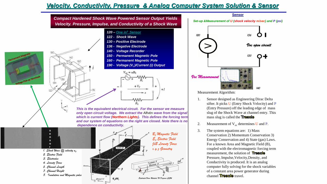
Velocity, Conductivity, Pressure & Analog Computer System Solution & Sensor
Sensor
Set-up &Measurement of U (shock velocity m/sec) and P (psi)
Compact Hardened Shock Wave Powered Sensor Output Yields
Velocity. Pressure, Impulse, and Conductivity of a Shock Wave
120 – One in3 Sensor
122 - Shock Wave
130 – Positive Electrode
136 - Negative Electrode
140 - Voltage Recorder
150 - Permanent Magnetic Pole
160 - Permanent Magnetic Pole
190 - Voltage (Vt )/Current (i) Output
B0 Magnetic Field
E0 Electric Field
JxB Lorentz Force
x,y,z Geometry
i
5. Channel Length
7. Channel Height
8. Insulators and Magnetic poles
1. Shock Wave @ velocity u0
2. Electric Field
3. Electrodes
4. Lorentz Force
Voc& Vt
120
130
136
140
Voc open circuit
Measurement Algorithm:
1. Sensor designed as Engineering Dirac Delta
sifter. It picks U (Entry Shock Velocity) and P
(Entry Pressure) off the leading edge of mass
slug of the Shock Wave at channel entry. This
mass slug is called the
2. Measurement of Voc determines U and P.
3. The system equations are: 1) Mass
Conservation 2) Momentum Conservation 3)
Energy Conservation and 4) State (gas) Laws.
For a known Area and Magnetic Field (B),
coupled with the electromagnetic forcing term
measurement, the solution of
Pressure, Impulse,Velocity,Density, and
Conductivity is produced. It is an analog
computer fully solving for the shock variables
of a constant area power generator during
channel travel.
Voc Measurement
This is the equivalent electrical circuit. For the sensor we measure
only open circuit voltage. We extract the Alfvén wave from the signal
which is current flow (Northern Lights). This defines the forcing term
and our system of equations on the right are closed. Note there is no
dependence on conductivity.
s
e
n
s
o
r
Vparticle
VAlfvén
Dis
co
ntin
uity
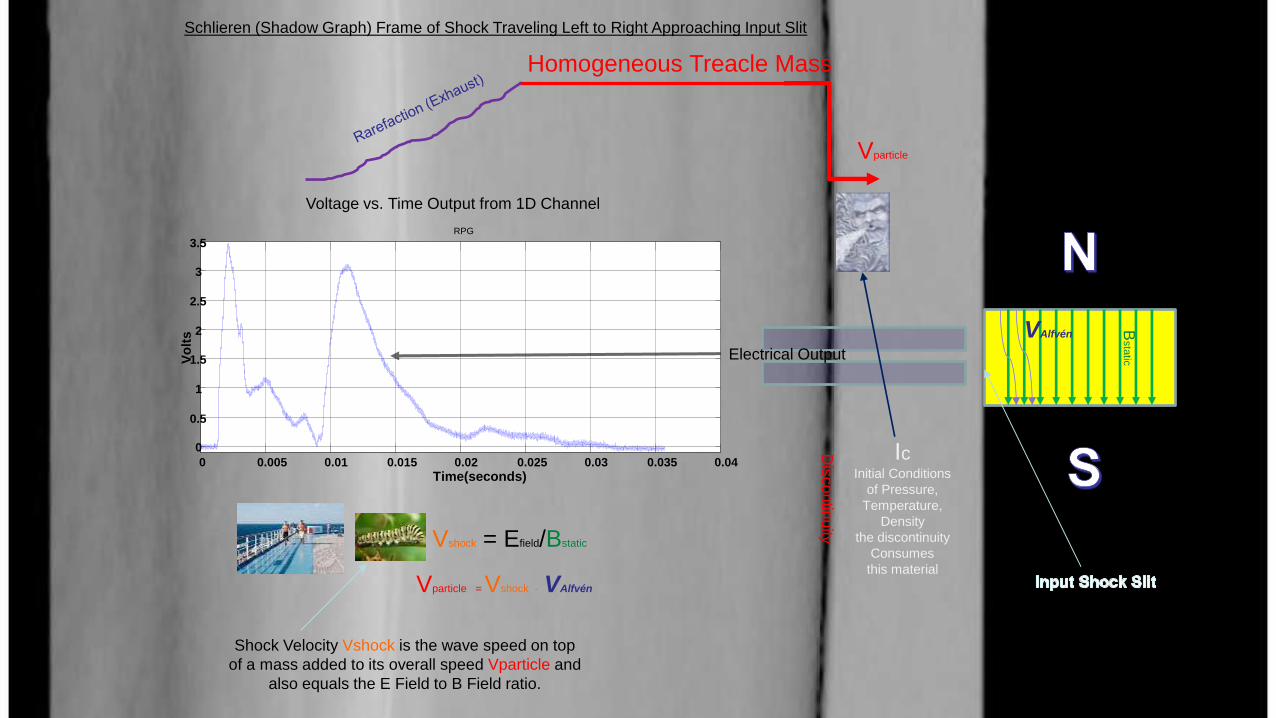
Homogeneous Treacle Mass
Vshock = Efield/Bstatic
Bsta
tic
Vparticle = Vshock - VAlfvén
Ic Initial Conditions
of Pressure,
Temperature,
Density
the discontinuity
Consumes
this material
Voltage vs. Time Output from 1D Channel
Shock Velocity Vshock is the wave speed on top
of a mass added to its overall speed Vparticle and
also equals the E Field to B Field ratio.
Schlieren (Shadow Graph) Frame of Shock Traveling Left to Right Approaching Input Slit
Electrical Output
0 0.005 0.01 0.015 0.02 0.025 0.03 0.035 0.04
0
0.5
1
1.5
2
2.5
3
3.5
Time(seconds)
Vo
lts
RPG
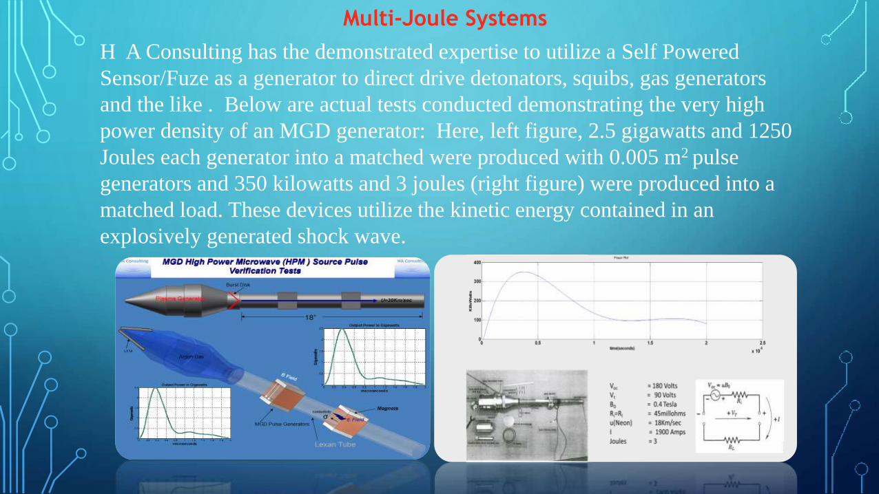
Multi-Joule Systems
H A Consulting has the demonstrated expertise to utilize a Self Powered
Sensor/Fuze as a generator to direct drive detonators, squibs, gas generators
and the like . Below are actual tests conducted demonstrating the very high
power density of an MGD generator: Here, left figure, 2.5 gigawatts and 1250
Joules each generator into a matched were produced with 0.005 m2 pulse
generators and 350 kilowatts and 3 joules (right figure) were produced into a
matched load. These devices utilize the kinetic energy contained in an
explosively generated shock wave.
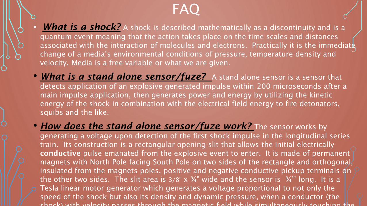
FAQ
• What is a shock? A shock is described mathematically as a discontinuity and is a
quantum event meaning that the action takes place on the time scales and distances
associated with the interaction of molecules and electrons. Practically it is the immediate
change of a media’s environmental conditions of pressure, temperature density and
velocity. Media is a free variable or what we are given.
• What is a stand alone sensor/fuze? A stand alone sensor is a sensor that
detects application of an explosive generated impulse within 200 microseconds after a
main impulse application, then generates power and energy by utilizing the kinetic
energy of the shock in combination with the electrical field energy to fire detonators,
squibs and the like.
• How does the stand alone sensor/fuze work? The sensor works by
generating a voltage upon detection of the first shock impulse in the longitudinal series
train. Its construction is a rectangular opening slit that allows the initial electrically
conductive pulse emanated from the explosive event to enter. It is made of permanent
magnets with North Pole facing South Pole on two sides of the rectangle and orthogonal,
insulated from the magnets poles, positive and negative conductive pickup terminals on
the other two sides. The slit area is 3/8” x ¾” wide and the sensor is ¾’’ long. It is a
Tesla linear motor generator which generates a voltage proportional to not only the
speed of the shock but also its density and dynamic pressure, when a conductor (the
shock) with velocity passes through the magnetic field while simultaneously touching the
pickup terminals. Tesla, using rigid body conductors, turned this phenomenon into its
rotational equivalent that we know today as the industry standard motor generator.
•
•
FAQ What is the value of the sensor output and in the event there is no free charge (no conductivity) in the shock media would there be no output from the sensor? The sensor as constructed with a ¼ Tesla B Field produces 1.5Volts/Mach. In the event there is no free charge in the media there would be no output during media transit through the magnetic field. However this is not a possibility as the physics of a discontinuity prohibits the situation where free electrons (charge) could not exist. The question is whether or not the sensor’s output is dependent on the amount of charge which is expressed as media conductivity in mohs/meter. The sensor follows theTesla per unit equation which states: Open Circuit Voltage = B(field)*Media Velocity. As this definition of open circuit voltage is the measurement of voltage into an infinite resistance, in the limit, an infinite resistance would require 1/infinity conductivity or one electron. Tesla’s equation therefore satisfies the limit. Practically though measurements are subject to stray capacitance, inductance, and wiring resistance and measurement input impedances. These additional parameters call for additional current over one electron. The standard oscilloscope measurement is a 1 Megohm load with a 15 pfarad capacitor in parallel, a long way from infinity. 10X and 100X probes, which resemble more the input to a Field Effect Transistor, are 10 Megohm and 100 Megohm again with 15 pfarad capacitors in parallel. HA Consulting has made unequivocal that the practical call for current from standard circuits would not affect the linearity of the sensor measurement.
•
•
FAQ Quantum arguments aside it is still hardly intuitive that a system that requires conductivity has no conductivity dependence. How can this be? There is conductivity dependence and it is as described physical call for current constraints, but there is also direct dependence in the power output of the device. Again Tesla’s expanded formulation states power output is a function of the square of the product of both media velocity and B Field, but only up to a certain value of conductivity. After that it is not dependent on conductivity rather linear with velocity but still dependent on the B Field squared. This left the fluid dynamics theorists’cold for some 60 years and it was not until the late 1960’s that a full and proper theory of a compressible media’s transit through a B field was published (REF: Electromagnetodynamics of Fluids – Chapter 11 – by Hughes and Young). To adequately describe the two fluid flow phases and their dependence on conductivity the fluid theorists crafted the unitless Magnetic Reynolds Number which is linearly dependent on the product of conductivity and fluid flow velocity. It conveniently turns out that the boundary between dependence and independence of conductivity is a Magnetic Reynolds Number of 1.
BACK UP SLIDES SHOWING SENSOR
MEASUREMENTS AND AN ANALOG
• Falling chain analog
• 4Kg C4
• Shape Charge
• 250 # explosive charge

Falling Chain Analog to Explosive Detonation
and ----------Impulse Accumulation An explosive event burns a solid material producing gases. However in the case of an explosive event the term burning carries a different
meaning than thought of when applied to the burning of a common solid material such as wood. The end effects are the same in that both
produce gases and heat, but at a highly different rate. Explosive theory holds that there are two different states in the chemical reaction
rate (the rate of change from a solid to a gas) in an explosive material. Deflagration, sometimes called burning, but not to be confused
with the burning of everyday material, is a slower event than detonation of solid material by about an order of magnitude. The chemical
reaction rate of detonation is in the range of 5 to 10 kilometers per second ( Km/sec). This very high reaction rate is the reason a
detonated explosive event is so much more energetic than the burning of everyday solids or even deflagration of the material, as kinetic
energy goes by the square of the rate or speed of the reaction. When an explosive detonates it produces a train of impulses of different
amplitude pressure and time. If allowed to progress in open air the slower pulses of lower pressure amplitudes are overtaken by the faster
pulses of higher pressure amplitudes and constructively interact forming one major event called a shock which propagates in the open air
media. This is called the far field of an explosive event and occurs outside the visible fireball witnessed in the detonation of explosives.
Inside the fireball is called the near field of an explosive event. It is chaotic and defined by many impulses spaced in time with different
pressure amplitudes and durations. In the case of an underbody event the action takes place in the near field as this train of impulses stack up
(accumulate) on the intervening underbody forming one main impulse applied to the body and defined as t=0. The action is best explained
with the following analog. Each pulse in the near field
resulting from the detonation
of an explosive is analogous
to a chain with different size
links falling on a platform.
The left figure shows the
links accumulating on a
platform, stacking up,
forming one main impulse
and transferring momentum
to the platform body. To the
right is the graph of the event
as the links accumulate
pressure over time. The area
under the curve is the main
impulse.
0 0.002 0.004 0.006 0.008 0.01 0.012 0.014 0.016 0.018-16
-14
-12
-10
-8
-6
-4
-2
0
2
4
0 0.5 1 1.5 2 2.5 3 3.5
x 10-5
-25
-20
-15
-10
-5
0
5
2.19 2.195 2.2 2.205 2.21 2.215 2.22 2.225
x 105
-14
-12
-10
-8
-6
-4
-2
0
2
4
0.8 1 1.2 1.4 1.6 1.8
x 10-3
-12
-10
-8
-6
-4
-2
0
2
B=0.252 Tesla; Va=225m/s B=0.265 Tesla; Va=250m/s B=0.256 Tesla; Va=225m/s B=0.272 Tesla; Va=243m/s
Vp = 2068; Vs=2293 P = (3703)(3953)(1)(0.00014503) = 2123psi
Vp = 2068; Vs=2293 P = (2068)(2293)(1)(0.00014503) = 688psi
Vp = 2068; Vs=2293 P = (2319)(2544)(1)(0.00014503) = 855psi
Vp = 2068; Vs=2293 P = (2236)(2479)(1)(0.00014503) = 804psi
Vo
lts
seconds
Pv
Pv
Pv D
isco
nti
nu
ity
Mass
1Kg/m3
Vs (Shock Vel.) = Va (Alfvén Vel.) + Vp (Particle Vel.)
o = Air Density in front of 1st Pulse Va = Predetermined Constant related to B Field
o Vp Vs
Pulse Train: Sensor measures first pulse only were the atmospheric conditions in front of pulse
are known.
o Vs = Pv / ((B)(d))
~4Kg C4 Ron Lundgren
HA Consulting
8653 W Rowland Place
Littleton, Co 80128
[email protected] 505-980-5458 (text me here)
AIO
2
AIO
1 AIO
4
AIO
3
Low Cost Measurement of Pressure Inside Occupant Enclosures i.e., Buses, Trains

s
V
-0.0006 -0.0002 0.0002 0.0006 0.001 0.0014-2
0
2
4
6
8
10B=0.272 Tesla; Va=260m/s
Vp = 1485; Vs=1745 P = (1485)(1745)(1)(0.00014503) = 376psi
Dis
con
tin
uit
y
Mass
1Kg/m3
Vs (Shock Vel.) = Va (Alfvén Vel.) + Vp (Particle Vel.)
o = Air Density in front of 1st Pulse Va = Predetermined Constant related to B Field
o Vp Vs
Pulse Train: Sensor measures first pulse only were the atmospheric conditions in front of pulse
are known.
o Vs = Pv / ((B)(d))
~12# TNT Cased
Ron Lundgren
HA Consulting
8653 W Rowland Place
Littleton, Co 80128
[email protected] 505-980-5458 (text me here)
Vo
lts
seconds
Detonation
40”
Pressure Surrounding a Cased Explosive Event for Collateral Damage Estimates
HOW IT WORKS IN THE FIELD W/EXPLOSIVES SENSOR OUTPUT FROM 250# SENSOR @ 16’
B=0.318 TESLA; FIRST LINK SHOCK VELOCITY = 16 VOLTS = 2475M/SEC; SENSOR
DETECTS BLAST CONSERVATIVELY 125 MICROSECONDS BEFORE IT STARTS TO
DESTRUCT; SENSOR MOUNTED MASS ~ 75 POUNDS
s
V
-0.001 0 0.001 0.002 0.003 0.004 0.005 0.006 0.007-10
-7.5
-5
-2.5
0
2.5
5
7.5
10
12.5
15
17.5
20
Fir
st
Chain
Lin
k