development of handling qualities criteria for … verde center #217 - 2075 palos verdes dr. north -...
TRANSCRIPT
VISTA VERDE CENTER #217 - 2075 PALOS VERDES DR. NORTH - LOMITA, CA 90717 - (310) 325-7255 - FAX 325-7234
DEVEOPMENT OF HANDLING QUALITIESCRITERIA FOR ROTORCRAFT WITH
EXTERNALLY SLUNG LOADS
Roger H. HohHoh Aeronautics, Inc.
Lomita, CA
Robert K. HeffleyRobert Heffley Engineering
Palo Alto, CA
ABSTRACTHandling qualities criteria have been developedfor cargo helicopters carrying externally slungloads in the degraded visual environment.These consist of quantitative criteria, as well asguidelines for qualitative flight test evaluations.The work was accomplished during severalsimulation programs conducted on the NASAAmes Vertical Motion Simulator.
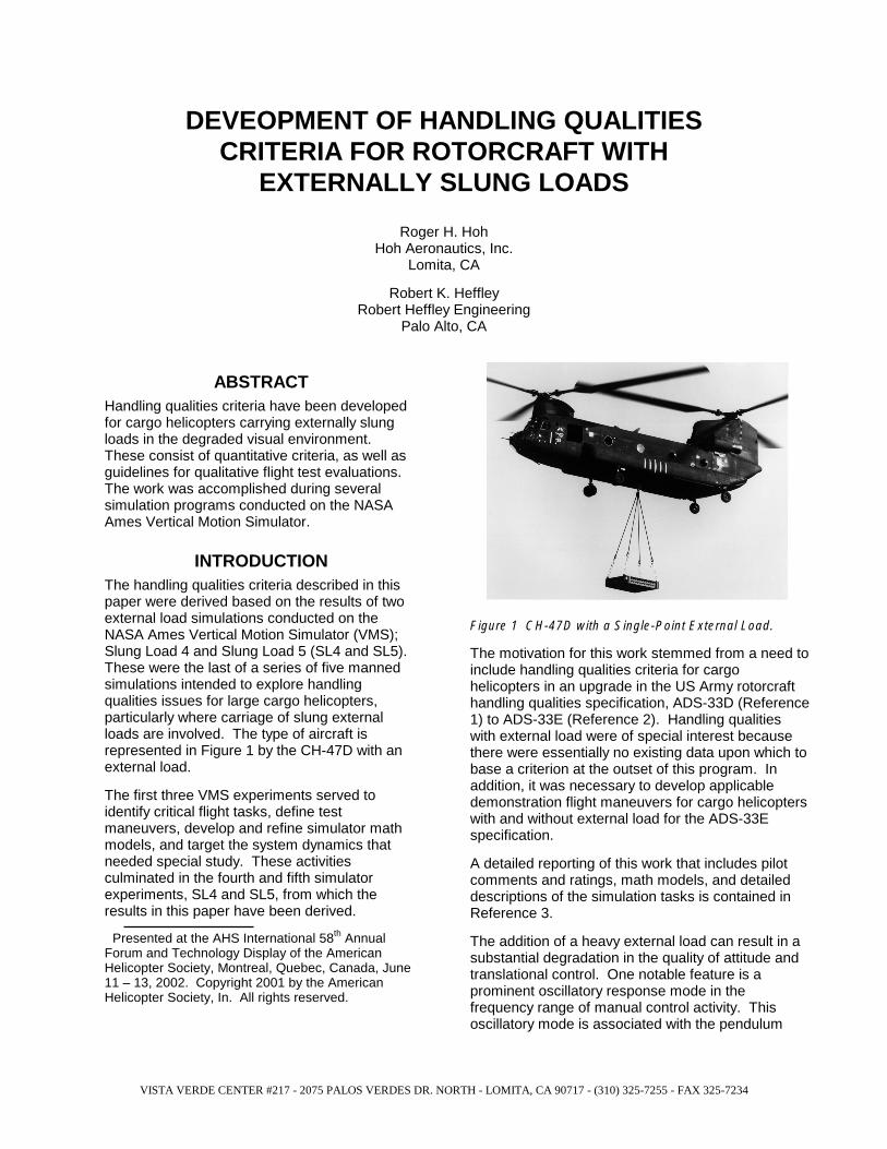
INTRODUCTIONThe handling qualities criteria described in thispaper were derived based on the results of twoexternal load simulations conducted on theNASA Ames Vertical Motion Simulator (VMS);Slung Load 4 and Slung Load 5 (SL4 and SL5).These were the last of a series of five mannedsimulations intended to explore handlingqualities issues for large cargo helicopters,particularly where carriage of slung externalloads are involved. The type of aircraft isrepresented in Figure 1 by the CH-47D with anexternal load.
The first three VMS experiments served toidentify critical flight tasks, define testmaneuvers, develop and refine simulator mathmodels, and target the system dynamics thatneeded special study. These activitiesculminated in the fourth and fifth simulatorexperiments, SL4 and SL5, from which theresults in this paper have been derived.
Presented at the AHS International 58th AnnualForum and Technology Display of the AmericanHelicopter Society, Montreal, Quebec, Canada, June11 – 13, 2002. Copyright 2001 by the AmericanHelicopter Society, In. All rights reserved.
Figure 1 CH-47D with a Single-Point External Load.
The motivation for this work stemmed from a need toinclude handling qualities criteria for cargohelicopters in an upgrade in the US Army rotorcrafthandling qualities specification, ADS-33D (Reference1) to ADS-33E (Reference 2). Handling qualitieswith external load were of special interest becausethere were essentially no existing data upon which tobase a criterion at the outset of this program. Inaddition, it was necessary to develop applicabledemonstration flight maneuvers for cargo helicopterswith and without external load for the ADS-33Especification.
A detailed reporting of this work that includes pilotcomments and ratings, math models, and detaileddescriptions of the simulation tasks is contained inReference 3.
The addition of a heavy external load can result in asubstantial degradation in the quality of attitude andtranslational control. One notable feature is aprominent oscillatory response mode in thefrequency range of manual control activity. Thisoscillatory mode is associated with the pendulum

action of the load, and couples with thefundamental response of the basic airframe-Stability-Command-Augmentation-System(SCAS) system. Because of this, a fundamentalunderstanding of the dynamics of external loadsas they relate to aircraft handling is essential todevelopment of criterion parameters. Much ofthe existing literature on external loads wasproduced during the 1970’s, and treats mainlythe matter of describing the dynamics. Theeffect of an externally slung load on handlingqualities, particularly in terms of contemporarymetrics and standards, has not been studied indetail prior to this effort.
The Attitude Bandwidth Criterion has been foundto be an effective means to ensure that theshort-term attitude response is sufficiently crispand predictable to maneuver with adequateaggressiveness and precision, when flyingwithout an external load (see References 2, and3). The hypothesis of the SL4 and SL5 pilotedsimulator experiments was to test theapplicability of Attitude-Bandwidth type criteriawhen a heavy external load is attached.Analyses of the simulation data and pilotcommentary revealed that the bandwidth of thetranslational rate response is a better handlingqualities metric than attitude bandwidth forhelicopters with external loads.
OVERVIEW OF SIMULATIONAll simulations to support this program wereconducted on the NASA Ames Vertical MotionSimulator (VMS) facility at Moffett Field, CA.This facility provides large-amplitude motion, afour-window ESIG-2000 visual system, and ageneric cockpit with controls and instrumentsrepresentative of a large cargo helicopter.
The aircraft math model was based on the CH-47D Chinook airframe and propulsion system.The flight control system was modified to reflecta generic attitude-command/attitude-hold(ACAH) Response-Type in pitch and roll. AnAltitude-Hold system (HH) was alsoimplemented and used for all data runs. Theuse of ACAH + HH is consistent with therequirement for Response-Type in ADS-33D/Efor flight in a degraded visual environment(DVE). Specifically, when the useable cueenvironment (UCE) is greater than 1, ADS33D/E requires an ACAH+HH Response-Typefor Level 1 handling qualities. The simulationvisual scene was measured using thetechniques in ADS-33D/E, resulting in UCE = 2
(albeit very close to UCE=1), which is judged to bedue to a lack of sufficient fine grained texture (seeReference 5).
The UCE=2 rating implies that a Rate Response-Type, that is normally rated as Level 1, would receivehandling qualities ratings (HQRs) consistent withLevel 2 due to a lack of adequate visual cueing.
The NASA Ames Vertical Motion Simulator iscapable of a reasonably valid representation ofexternal load operations by virtue of its largeamplitude motion system. However, even with thelarge field-of-view visual, and large amplitude lateraland vertical motion, the cueing was somewhatcompromised compared to the real world. Motioncues have a significant impact on the pilot’simpressions of the swinging load, and even with themaximum possible motion gains, the actualaccelerations at the cockpit were approximately 1/10of those experienced in the real world. Nonetheless,the pilots commented that the motions wererepresentative of their experience in carryingexternal loads, and that the motion was beneficial inthe conduct of their evaluations.
The pilots were not able to see the load, andtherefore had to deduce what the load was doingfrom motion and visual cues. The hover altitude wasfixed at 50 ft so that the visual cues were constantfor all runs. This artifact resulted in the longer slingsbeing partially under ground. The pilots were notable to observe this artifact.
The motion gains in simulation SL5 were appreciablyhigher than in simulation SL4. This resulted from amotion gain optimization process that concentratedon the Precision Hover maneuver in SL5. SL4 tasksincluded Precision Hover, Normal Departure Abort,and Lateral Reposition (See Reference 3). The VMScab was oriented to maximize longitudinal motion forthe Normal Departure Abort, and was re-oriented 90degrees to maximize lateral motion for the PrecisionHover and Lateral Reposition. Only the PrecisionHover Maneuver was accomplished in SL5, becausethe results of SL4 indicated that this was the mostcritical maneuver. The reason for this is that theeffect of the swinging load is most noticeable whenattempting to accomplish very precise positioncontrol. All of the data correlations in this paper arebased on the Precision Hover task. The pilot ratingsfor the precision hover, and for other maneuvers aregiven in Reference 3.
All of the results discussed herein are based on ahigh density load suspended from a single point at ordirectly below the helicopter center-of-gravity (c.g.).Load aerodynamics were not simulated.

QUANTITATIVE CRITERIAThe quantitative handling-qualities criteria forrotorcraft with external loads, that resulted fromthis study, are presented in this section. Furtherwork should be accomplished to verify thesecriteria in a flight test environment. Such testingshould also examine the ability to reliablymeasure the criterion parameters. This workshould be accomplished before the quantitativecriteria are included as an update to ADS-33E(Reference 2). Once included in ADS 33, it isexpected that the quantitative criteria would beused in lieu of the Attitude Bandwidth criteria forconfigurations with an external load.
In addition to the quantitative criteria, flight testmaneuvers and performance criteria weredeveloped for cargo helicopters with externalload. These maneuvers and performancecriteria are given in Reference 3 and have beenincluded in ADS-33E.
The quantitative criteria apply to low speed andhover operations in the DVE with UCE = 2. If theoperational missions do not require carrying anexternal load in the DVE, it is not necessary tomeet the quantitative criteria for external loads.
The external-load bandwidth criteria provideguidance as to what is required to obtain Level 1pilot ratings with load-on in the DVE, in additionto meeting the load-off handling qualities criteriain ADS-33. These external-load criteria arebased on the assumption that the basicrotorcraft without an external load is Level 1. It iscautioned that the combination of not meetingthe external-load criteria, and a rotorcraft that isLevel 2, load-off, will probably result in Level 3handling qualities in the DVE.
The effect of the external load on handlingqualities was found to be a strong function of theLoad Mass Ratio - the ratio of the mass of theload to the mass of the helicopter plus load( TotalL mm / ). The effect of an external load on
helicopter handling qualities was found to besignificant when the Load-Mass-Ratio is equal toor greater than 0.33 of the total mass, i.e.,
33.0/ ≥TotalL mm .
The handling qualities criteria specific torotorcraft with external load are defined in termsof two parameters - Translational RateBandwidth and Load-Coupling.
The horizontal translation Bandwidths shall be asfollows for Level 1.
sec/59.0
sec/44.0
radLateral
radalLongitudin
Y
X
BW
BW
≥
≥
&
&
ω
ω
The frequency range of favorable load-coupling shallbe as follows for Level 1.
sec/73.0
sec/39.0
radLateral
radalLongitudin
Y
X
L
L
≥∆
≥∆
ωω
Not meeting these criteria will result in handlingqualities that are no worse than Level 2 with anexternally slung load in the DVE, as long as the load-off handling qualities are Level 1. There is no Level2-3 limit that is specifically due to external load.
The translational rate Bandwidth and Load-Couplingparameters are presented in detail in subsequentsections of this paper.
It is recognized that it may be difficult to obtain Bodeplots of translational rate-to-cyclic response withsufficient accuracy and resolution to accuratelymeasure these parameters. Therefore, it isacceptable to use an analytically derived Bode plot ifthe math model used to generate the Bode plot hasbeen shown to correlate with flight data for input-output responses other than the translational rate tocyclic. For example, if the analytically derived Bodeplots for pitch and roll attitude to cyclic inputs (withexternal load) is well correlated with flight test data,the math model may be assumed to be acceptableto calculate the translational-rate criterionparameters.
QUALITATIVE TESTING WITHEXTERNAL LOAD
Testing with external loads should be accomplishedwith 33.0/ =TotalL mm or the maximum load that willbe used for operational missions, whichever is less.In addition, external load testing should beaccomplished in the DVE, unless this is not part ofthe required operational missions. Therecommended maneuvers are given in Reference 3
The existence of an external load will degradehandling qualities, and it was not found to bepractical to require Level 1 as defined by averaged
HQRs less than 3.5 ( 5.3≤HQR ) for heavy loads.The simulations conducted in this program indicatedthat no combination of SCAS and sling geometryresulted in average ratings of better than 4 for
33.0/ =TotalL mm . On that basis, the requirementfor Level 1 during tests with external loads in the

DVE, with 33.0/ =TotalL mm , is relaxed so that the
average HQR ( HQR ) must be no greater than 4(compared to 3.5 load-off). The rationale for thisis that an HQR of 4 requires desiredperformance and some increased workload isunavoidable with a heavy external load in theDVE.
If 33.0/ >TotalL mm , the simulation studiesshowed that the ratings degrade linearly withincreasing Load Mass Ratio (shown later inFigure 11). The caveat being that the averagedratings did not exceed 6.5 for any of the testedcases. That is, the effect of a heavy swingingload never caused problems severe enough tobe classified as Level 3 (as long as the load-offhandling qualities were rated as Level 1).
Conversely it was shown that for load massratios less than 0.25, the effect of the load wasreduced to the point where averaged HQRs of3.5 or better were achievable. On the basis ofthose results, the maximum allowable averagedHQR as a function of load mass ratio is asfollows:
33.0/ >TotalL mmFor
−+≤ )33.0(2.50.4
Total
L
m
mHQR
33.0/25.0 ≤≤ TotalL mmFor - 0.4≤HQR
25.0/ ≤TotalL mmFor - 5.3≤HQR
In addition to testing for acceptable handlingqualities, it should be determined that any loadoscillations that occur during deceleration tohover are damped quickly enough so that theydo not interfere with the ability of the groundcrew to safely detach the load without damagingit, in a reasonable period of time.
DEVELOPMENT OF QUANTITATIVECRITERIA
The quantitative criteria developed in this studyapply to low speed and hover tasks, i.e., taskswhere the groundspeed is, for the most part,under 45 kts. The criteria are based on thePrecision Hover task as accomplished in twosimulations (SL4 and SL5). Other moreaggressive tasks were accomplished in SL4(Lateral Reposition, and Normal Depart/Abort)as described in Reference 3). The pilot ratingdata and commentary from SL4 indicated that
the Precision Hover task was the most critical task interms of handling qualities. That was because theperturbations that resulted from the swinging loadwere much more noticeable and intrusive whentrying to accomplish a precision station-keeping task.The SL5 simulation focused entirely on the PrecisionHover task.
The Precision Hover task included a moderatelyaggressive deceleration from a 6 to 10 kt.translation. This tended to excite the load, and thepilot was allowed 13 seconds to stabilize thehelicopter plus load oscillation for desiredperformance, and 18 seconds for adequateperformance. Desired performance required that thepilot maintain longitudinal and lateral position, withwithin a 3 ft hover box and altitude within 4 ft. for 30seconds. Adequate performance relaxed the hoverposition to a 6 ft box, and altitude to within 6 ft. for 30seconds.
Analysis of simulation data (SL4 and SL5) forvariations in external load and flight control systemcharacteristics has shown that pilot opinion wasstrongly impacted by changes in the characteristicsof the longitudinal and lateral translational velocityresponse. This is in contrast to the load-off casewhere pilot opinion is best correlated with attituderesponse characteristics. Without an external load,the attitude and translational rate responses arehighly correlated. This is not the case with anexternal load, where the phasing between thetranslational rate and attitude responses is highlydependent on the sling geometry, load-mass, andflight control system.
Recall that the basic hypothesis that was used toguide the development of test configurations for thisexperiment was that the Attitude Bandwidth criteriafor load-off could be extended to load-on.Considerable analysis was accomplished in anattempt to correlate the pilot rating data with variousdefinitions of Attitude Bandwidth (see Reference 3,Appendix E). This was ultimately not successful,which led to correlation efforts using thecharacteristics of the surge and sway (translationalvelocity yandx && ) responses.1
Good position control is dependent the ability of thepilot to precisely control speed. It follows that thecriteria development effort can be focused on an
1 The correlation of pilot rating data with surge and swaycharacteristics was also suggested by pilot commentary thatindicated significant concern with those degrees of freedom(see Reference 3).

analysis of the cxtox && loop closure. That is, the
shape of the frequency response ofδδ // yandx && can be quantified, and correlated
with pilot opinion and ratings from the SL4 andSL5 simulation experiments. These dynamicscan be related to physical characteristics suchas sling geometry (e.g., hook-to-c.g. distanceand sling length) and flight control systemcharacteristics.
A quantitative criterion could not be derived forRate Response-Types with an external load, soit is necessary to check the handling qualitiesusing specified flight test maneuvers as providedin References 2 or 3, and the pilot ratingguidelines noted above in the section onQualitative Testing With External Load.
The development of quantitative criteria forexternal loads with Rate Response-Types wasnot possible because the simulation visualenvironment was measured to be UCE = 2(using the techniques in ADS-33D/E). Pilotedevaluations of a Level 1 Rate System with thenominal load, resulted in HQRs of 7 – 8. Thisverified that the simulation environment wasUCE=2, because it is well known that Level 1handling qualities are possible with RateResponse Types in UCE=1. The remainder ofthis development pertains to an ACAHResponse-Type.
A typical frequency response and root locus plotthat describes the longitudinal velocity responseto longitudinal cyclic input is shown in Figure 2for a helicopter without a load. The effect ofadding an external load that is suspended from asingle point is shown in Figure 3. Comparison ofthe dynamics in Figures 2 and 3 reveal that theshort-period mode ( spω ) is only slightly affected,
and that the primary effect of the load on thesurge response is described by the addition of alightly damped pole-zero complex pair1.
The effect of increasing the pilot gain, Kpilot, isindicated by the root locus plots in Figures 2band 3b. These plots indicate the followingresults.
• An increase in xT&/1 which defines thefundamental speed and path response
1 The generic effect of external load on the lateral axis isvery similar to the longitudinal axis and is therefore notdiscussed separately.
(Load on and off). Higher values of
xT&/1 allow for a more predictable velocityresponse and hence a more stable positionloop closure.
• Decrease in damping of the short periodmode (load on and off).
• The load-mode pole (PLω ) is driven towards
decreased damping and eventually unstable(load-on only).
Good handling qualities would be expected to existwhen the pilot is able to augment the basic pathmode, xT&/1 , without driving the short period mode
( spω ) and/or load-mode (pLω ) poles to unacceptably
low damping or unstable.
Figure 2 Bode and Root Locus for Load-Off

Figure 3 Bode and Root Locus With Load On
It will be shown that the ability to augment xT&/1
to the level needed to accomplish the task isdefined by the Translational Rate Bandwidthparameters,
YX BWBW and&&
ωω 1. That is, low
Bandwidth is an indicator that the pilot loopclosure will result in low xT&/1 (and hence poorcontrol of speed and position). Bandwidth iseither limited by stability considerations, or by theload mode zero. The natural frequency of theload mode zero Lω is approximated by,
1 Bandwidth as used in this Report refers to theTranslational Rate Bandwidth unless otherwise noted.As with the attitude Bandwidth, it is defined as thefrequency for 45 degrees of phase margin and 6 dB ofgain margin.
totalmhelomslingl
gL /*
≅ω where slingl is the
length of the sling (hook to c.g. of load).
Note that when the load mass is much less than thetotal mass ( 1/ ≈totalhelo mm ), the load-mode zero has
the frequency of a classic pendulum, lg /=ω .
The load-mode pole always occurs in the vicinity ofthe load mode zero.
Without an external load, Bandwidth is defined inADS-33D/E as the frequency where the phasemargin is equal to 45 degrees, or the gain margin isequal to 2 (6 dB) in the attitude response. As anexample, the piloted crossover in Figure 2 is shownto occur at the bandwidth frequency (phase margin is45 degrees).
The effect of pilot gain on the crossover frequencycan be determined by noting that the crossoverfrequency occurs when 01 =+ GK pilot or
pilotKG /1−= (where G is δ/x& )2. We can
graphically determine the crossover frequency byplotting pilotK/1 and δ/x& on the same grid and
noting where they intersect. Normally there is oneintersection, and that is defined as the crossoverfrequency. The conventional definition of Bandwidthis when this crossover frequency occurs at –135 degof phase or 45 deg of phase margin (e.g., Figure 2).
For the external load case, the translational-rateresponse is used, and the additional mode inducedby the load results in several piloted crossoverfrequencies as shown in Figure 3. The “lowcrossover frequency” is akin to the classical pilotedcrossover illustrated in Figure 2. The “highcrossover frequency” occurs due to the load mode.The fact that the pilot gain-line (1/Kpilot) intersects theload mode peak, indicates that these dynamics arebeing excited. The phase margin for this highcrossover determines the load stability.
The concept of the “high crossover” allows theinclusion of load stability as a factor in the handlingqualities criteria. Without an external load,Bandwidth is defined by two parameters, gain andphase margin of the basic augmented aircraft.Adding the effect of an external load requires theaddition of two additional parameters. These are thegain and phase margin associated with the load
2 See Reference 6 for a more complete description of pilot-vehicle analysis procedures.
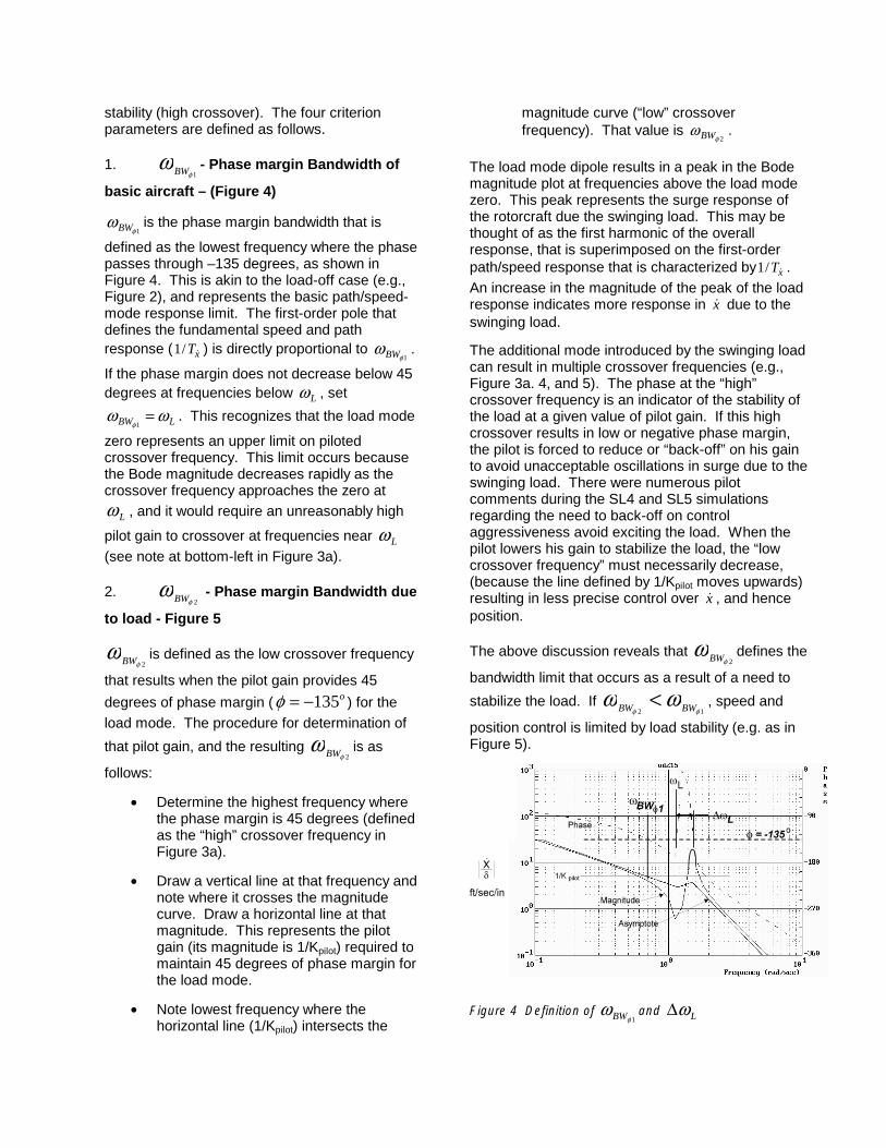
stability (high crossover). The four criterionparameters are defined as follows.
1.1φ
ω BW - Phase margin Bandwidth of
basic aircraft – (Figure 4)
1φωBW is the phase margin bandwidth that is
defined as the lowest frequency where the phasepasses through –135 degrees, as shown inFigure 4. This is akin to the load-off case (e.g.,Figure 2), and represents the basic path/speed-mode response limit. The first-order pole thatdefines the fundamental speed and pathresponse ( xT&/1 ) is directly proportional to
1φωBW .
If the phase margin does not decrease below 45degrees at frequencies below Lω , set
LBW ωωφ
=1
. This recognizes that the load mode
zero represents an upper limit on pilotedcrossover frequency. This limit occurs becausethe Bode magnitude decreases rapidly as thecrossover frequency approaches the zero at
Lω , and it would require an unreasonably high
pilot gain to crossover at frequencies near Lω(see note at bottom-left in Figure 3a).
2.2φ
ω BW - Phase margin Bandwidth due
to load - Figure 5
2φω BW is defined as the low crossover frequency
that results when the pilot gain provides 45
degrees of phase margin ( o135−=φ ) for theload mode. The procedure for determination of
that pilot gain, and the resulting2φ
ω BW is as
follows:
• Determine the highest frequency wherethe phase margin is 45 degrees (definedas the “high” crossover frequency inFigure 3a).
• Draw a vertical line at that frequency andnote where it crosses the magnitudecurve. Draw a horizontal line at thatmagnitude. This represents the pilotgain (its magnitude is 1/Kpilot) required tomaintain 45 degrees of phase margin forthe load mode.
• Note lowest frequency where thehorizontal line (1/Kpilot) intersects the
magnitude curve (“low” crossoverfrequency). That value is
2φω BW .
The load mode dipole results in a peak in the Bodemagnitude plot at frequencies above the load modezero. This peak represents the surge response ofthe rotorcraft due the swinging load. This may bethought of as the first harmonic of the overallresponse, that is superimposed on the first-orderpath/speed response that is characterized by xT&/1 .An increase in the magnitude of the peak of the loadresponse indicates more response in x& due to theswinging load.
The additional mode introduced by the swinging loadcan result in multiple crossover frequencies (e.g.,Figure 3a. 4, and 5). The phase at the “high”crossover frequency is an indicator of the stability ofthe load at a given value of pilot gain. If this highcrossover results in low or negative phase margin,the pilot is forced to reduce or “back-off” on his gainto avoid unacceptable oscillations in surge due to theswinging load. There were numerous pilotcomments during the SL4 and SL5 simulationsregarding the need to back-off on controlaggressiveness avoid exciting the load. When thepilot lowers his gain to stabilize the load, the “lowcrossover frequency” must necessarily decrease,(because the line defined by 1/Kpilot moves upwards)resulting in less precise control over x& , and henceposition.
The above discussion reveals that2φ
ω BW defines the
bandwidth limit that occurs as a result of a need to
stabilize the load. If12 φφ
ωω BWBW < , speed and
position control is limited by load stability (e.g. as inFigure 5).
Figure 4 Definition of1φ
ωBW and Lω∆

This was more common in the pitch axis,because the high moment of inertia in that axistended to suppress favorable coupling betweenthe load and pitch attitude (see subsequentdiscussion on Lω∆ ).
Figure 5 Definition of2φ
ωBW
3.1GBWω - Gain margin Bandwidth of
basic aircraft - Figure 6
This parameter is equivalent to the gain-marginbandwidth used for load-off handling qualities.
The definition of1GBWω is illustrated in Figure 6
and is calculated as follows.
1) Find the Bode magnitude that occurs atthe lowest frequency where the phase equalsminus180 deg (this is defined as the pilotcrossover for neutral stability; 1/Kpilot = G at thefrequency where o180−=φ )
2) Find the lowest crossover that occurs ifthe pilot reduces the gain calculated in step 1 by
1/2 or 2/Kpilot. This is1GBWω .
As an aside, note that this illustration uses thelateral response as an example. A longitudinalexample could just as easily have been used, asthe dynamics are the same.
4.2GBWω - Gain margin Bandwidth due
to load – (Figure 7)
This parameter defines the gain margin limitassociated with stabilization of the load mode. Itis the gain margin limit that goes along with the
2φω BW phase margin limit. The definition of
2GBWω is illustrated in Figure 7 and is calculated as
follows
1) Find the magnitude that occurs at thehighest frequency where the phase equals –180deg. This is the pilot gain (1/Kpilot) for neutral loadstability
2) Find the lowest crossover that occurs if thepilot reduces the gain calculated in step 1 by 1/2 or2/Kpilot. This is
2GBWω .
5. Lω∆ - Load Coupling Parameter –
(Figure 4)
The load coupling parameter, Lω∆ , defines the
range of frequencies where the phase of theswinging load results in damping of speed and pathexcursions. The mechanism is as follows. If theload swings forward, the momentum of the load willtend to increase the forward velocity. However, if theforward load swing causes the helicopter to pitch up,the horizontal component of the lift vector will opposethe increase in speed. If the net effect is to dampthe overall motion, the load coupling is said to befavorable. Such favorable load coupling manifestsas positive phase margin in the vicinity of the load-mode dipole.
Lω∆ is defined as the range of frequencies wherethe phase margin is equal to or greater than 45degrees, as shown in Figure 4.
Increasing the hook-to-c.g. distance below thevertical c.g. of the helicopter tends to improvefavorable load-mode coupling (larger Lω∆ ), becausethe effect of the swinging load on pitching moment isincreased. Conversely increasing the pitch momentof inertia tends to reduce Lω∆ since the aircraftdoes not pitch as much due to the applied momentof the swinging load.

Figure 6 Definition of1GBWω
Figure 7 Definition of2GBWω
TESTED CONFIGURATIONSThe SL4 and SL5 VMS simulations wereaccomplished to verify, or if necessary, modifythe hypothesis that the handling qualities ofhelicopters with external load can be specifiedusing an extension of the basic AttitudeBandwidth Criteria in ADS-33D. The requiredperturbations in Attitude Bandwidth wereachieved through systematic variations inexternal load parameters as well as a variablelag-lead filter in the flight control system. Theseparametric variations are summarized asfollows.
• Sling length from 20 to 150 ft
• Hook-to-c.g. distance from 0 to 21 ft(below the c.g.)
• Attitude-Command-Attitude-Hold(ACAH) flight control systems with loadoff Bandwidths of 2.6 rad/sec (ACAH1)2.0 rad/sec (ACAH2), and 1.17 rad/sec(ACAH3) and 0.7 rad/sec (ACAH4). The
gains were adjusted so that the pitch and rollbandwidths were identical in hover.
• Effect of lag-lead equalization on ACAH1and ACAH2
• Effect of ratio of load weight to helicopterweight. (load + helicopter weight was heldconstant at 46000 lbs). This included somecases with no load, which served as abaseline, and provided data for internallyloaded cargo helicopters (see Reference 3).
• Effect of variation in roll moment of inertia.Results of this are given in Reference 3.
A complete description of the configurations is givenin Reference 3.
CORRELATION WITH BANDWIDTH ANDLOAD COUPLING PARAMETERS
The pilot rating data from SL4 and SL5 for thePrecision Hover Task are plotted on a grid ofBandwidth vs. the Load Coupling Parameter, Lω∆ inFigures 8 and 9 for the nominal 16,000 lb load.
The pilot rating data indicates that with a load massratio of 0.33 or greater (16000 lb or greater load) itwas not possible to achieve the commonly accepted
definition of Level 1 ( 5.3≤HQR ) with any of theconfigurations. A review of the pilot commentaryreveals that this was due to the uncommandedmotions of the rotorcraft resulting from the swingingload. With lighter loads these motions were lessobjectionable, and average HQRs of 3.5 or betterwere common. The effect of load mass is furtherdiscussed in a subsequent section.
As discussed earlier, the Level 1-2 boundariesshown in Figures 8 and 9 were based on HQR=4.
With only one exception, the pilot ratings never wereworse than 6.5. Therefore, a Level 2-3 boundarycould not be derived. Decreasing Bandwidthresulted in a gradual degradation in HQR, whereasunfavorable load coupling was found to be moreobjectionable.

0 0.1 0.2 0.3 0.4 0.5 0.6 0.70
0.1
0.2
0.3
0.4
0.5
0.6
0.7
0.8
0.9
1
3.5
1103.5
120
4.3130
4.5140
4.5240
6.5217
5.6215
4.6214
3.9
210
4.1220
5.1230
4160
4.7165
6.4166
3.9
150
4.91557
156
3.7191
4.4192
ωBWx
(rad/sec)
∆ωLx
(rad
/sec
)
Leve
l 1
Leve
l 2
Load mass ratio = 0.33
HQR
Configuration
Figure 8 Correlation of Cooper-Harper Pilot RatingData for Longitudinal Axis
0 0.1 0.2 0.3 0.4 0.5 0.6 0.7 0.8 0.9 10
0.5
1
1.5
2
2.5
3
3.5110
3.51204.3
130
4.5140
4.5240
5.6215
4.6214
3.9210
4.1220
5.1230
4160
4.7165
6.4166
3.9150
4.9155
7156
ωBWy
(rad/sec)
∆ω
Ly
(ra
d/s
ec)
Leve
l 1
Leve
l 2
6.5217
Load mass ratio = 0.33
HQR
Configuration
3.7191
4.4192
Figure 9 Correlation of Cooper-Harper Pilot RatingData for Lateral Axis
The Level 1-2 boundaries shown in Figures 8 and 9provide a reasonably good separation for casesrated worse than HQR = 4 and those that were ratedbetter. Cases that are rated Level 2 and fall in theLevel 1 region in one axis, tend to fall in the Level 2region in the other axis. For example Case 230 fallsin the Level 1 region for the longitudinal axis and theLevel 2 region for the lateral axis. It is rated Level 2
( 1.5=HQR ).
The effects of sling geometry, load mass, and lag-lead compensation in the flight control system areisolated and discussed in the following paragraphs
EFFECT OF LOAD MASS RATIOAs would be expected, the load mass ratio (mass ofload divided by total mass) had a strong effect onhandling qualities. When excited, the swinging loadresulted in un-commanded translational motions,which were directly proportional to the Load MassRatio. A typical pilot comment for the precisionhover task follows:
“When I would bring it to a stop, and try to back outof the loop during a hover, the oscillations of theairframe would cause the aircraft to translate fore oraft or left or right, depending on which way the loadwas going, which would take the aircraft out of thedesired box.”
The load also disturbed the pitch and roll attitude asevidenced by the following pilot commentary.
“I put an input in and then the load would respondand I could feel a lateral acceleration, like I wasbeing pulled sideways. And then some time afterthat, it seemed like I would get a roll in the oppositedirection, kind of a stabilizing effect.”
These effects scale directly with the Load MassRatio since a heavier load contributes moremomentum to the system. As noted by the abovecomment, the effect of the load on the aircraftresponse can be favorable. This effect is capturedby the Load Coupling Parameter, Lω∆ .
Decreasing the weight of the load results in adecrease in the load coupling parameter in thelongitudinal and lateral axes. That is because alighter swinging load does not impose a sufficientlylarge moment on the rotorcraft to provide thestabilization noted above. This results in smallvalues of Lω∆ that are in the Level 2 region.However, the light load also does not disturb thehelicopter sufficiently for the pilot to be concerned sothat the HQRs are Level 1. Because of this, the

Level 1-2 boundaries derived in Figures 8 and 9only apply when the load mass ratio issufficiently large ( 33.0/ =TotalL mm ).
It is not possible to determine the effect ofincreasing TotalL mm / beyond 0.33 with
confidence from the available data. Only twoconfigurations with load weight greater than16000 lbs were investigated (Configurations 189and 290), and these were both rated as Level 2.
The configurations where load weight wasindependently varied (sling length and hook-to-c.g., held constant at nominal values) indicate anessentially linear trend in pilot rating vs. loadmass ratio as shown in Figure 11. The effect ofincreased attitude bandwidth (ACAH1 vs.ACAH2) appears to be unimportant for loadmass ratios greater than 0.18 for these “nominal”cases (i.e, 20 ft sling and 7 ft hook-to-c.g.distance).
Figure 11 Effect of Load Mass Ratio on HandlingQualities Ratings
These data indicate that pilot ratings degrade asan essentially linear function of increasing loadweight. It follows that the proposed quantitativecriteria apply only for the tested load weight,
33.0/ =TotalL mm . The criteria are too stringentfor lighter loads and too lenient for heavier loads.Until more comprehensive criteria aredeveloped, it will be necessary to determine thehandling qualities for lighter and heavier loadsusing the maneuvers in Reference 3. The HQRsobtained from such evaluations are allowed todegrade according to the formula in Figure 11when 33.0/ ≥TotalL mm .
The qualitative flight test criteria given aboveallows the average HQR to degrade with
increasing load mass ratio per the formula in Figure11 when 33.0/ >TotalL mm . Conversely, when
25.0/ ≤TotalL mm , the data in Figure 11 indicate thatthe HQRs should be no worse than 3.5.
From a design standpoint, meeting the quantitativecriteria developed herein for 33.0/ =TotalL mm ,provides reasonable assurance that the bestpossible handling qualities are achieved for all loadweights. The caveat being that for much heavierloads, the best possible handling qualities may notbe very good. For such cases, the pilots arerequired to “fly the load”. Pilots who fly very heavyloads refer to moving the helicopter over the load todamp the motion. It is normally not possible to dothis in the DVE, since the pilot cannot see the load(especially with night vision goggles). In that case,there seems no choice but to live with the increasedworkload and degraded performance. Meeting theBandwidth and Load Coupling criteria presentedabove ensures that the workload is as low aspossible.
EFFECT OF SLING LENGTHThe result obtained for variations in sling length areshown in Figure 12. These data indicate that thepilot commentary and ratings were not highlysensitive to sling length.

0.2 0.25 0.3 0.35 0.4 0.45 0.5 0.55 0.60.3
0.35
0.4
0.45
0.5
0.55
3.5
1103.5
120
4.3130
4.5140
4160
ωBWx
(rad/sec)
∆ωLx (
rad
/se
c)
Le
vel 1
Le
vel 2
a) Effect of Sling Length - Longitudinal Axis, ACAH1 Unless Otherwise Noted
0 0.1 0.2 0.3 0.4 0.5 0.6 0.7 0.8 0.9 10
0.5
1
1.5
2
2.5
3
3.5110
3.5120
4.3130
4.5140
4.5240
4160
ωBWy
(rad/sec)
∆ωLy
(rad
/sec
)
Leve
l 1
Leve
l 2
0.60
(ACAH2)
b) Effect of Sling Length - Lateral Axis, ACAH1 Unless Otherwise Noted
Lsling=31 ft
Lsling=20 ft
Lsling=48 ft
Lsling=79 ft
Lsling=150 ft
Lsling=54 ft
4.5240
(ACAH2)Lsling=54 ft
Lsling=20 ftLsling=48 ft
Lsling=31 ft
Lsling=79 ft
Lsling=150 ft
Figure 12 Effect of Sling Length
Longitudinal Axis – Increasing the sling lengthfrom 20 ft to 79 ft caused only small variations in
LXω∆ and Bandwidth (see Figure 12a). A
substantial increase in LXω∆ occurred when thesling length was increased to 150 ft(Configuration 140). The averaged pilot ratingsdid not vary significantly with sling length
( 5.3=HQR for 20 foot sling length and
5.4=HQR for 150 ft sling length). A detailedexamination of the data indicates a small butsteady degradation in pilot rating with increasingsling length. Case 160 (20 ft sling) received anumber of ratings of 3 and one 2.5. Case 140(150 ft sling) was frequently rated 4.5 to 5, andnever better than 3.5. The subtle nature of thedegradation with a long sling (due to decreased
lateral bandwidth) required a large number of runs toidentify.
There does not appear to be a handling-qualities cliffassociated with sling-length. There were numerouspilot comments that the system is well behaved if thepilot backs out of the loop (all sling lengths), whichwas due to the favorable load coupling ( Lω∆ ) thatexisted for all of the cases where sling length wasvaried.
All but one of the sling-length variation cases wererun with the higher attitude Bandwidth (ACAH1).Case (240) was run with a 54 ft sling and ACAH2
( 5.4=HQR ). Comparison with Configuration 120
(48 ft sling and ACAH1, with 5.3=HQR ) indicatesthat the effect of the attitude SAS is significant forlonger slings. This is discussed further under Effectof Higher Order Flight Control System and AttitudeBandwidth.
Lateral Axis – Increasing the sling length resulted ina monotonic decrease in bandwidth at approximatelyconstant LYω∆ (Figure 12b). The primary pilotcomplaint for Configuration 140 (150 ft sling) waslack of predictability, which is consistent with thedecreased lateral Bandwidth.
EFFECT OF HOOK-TO-C.G. DISTANCE,
hooklThe nominal value of hookl was 7 ft, which is thegeometry that is commonly used by the U.S. Armywhen carrying external loads on the CH-47. A rangeof hook-to-c.g. distances between 0 ft and 21 ft wastested. All of the hook-to-c.g. variations were runwith the lower attitude bandwidth system (ACAH2).
Increasing hookl from 0 to 21 ft resulted in acorresponding increase in the Load CouplingParameter, Lω∆ , from very low to very high valuesas shown in Figures 13a and 13b. This is a directresult of the increase in moment transmitted to therotorcraft from the swinging load as hookl isincreased. In the longitudinal axis, the translational

Figure 13 Effect of Hook-to-C.G. Distance
rate bandwidth increases steadily with hookl
(Figure13a), which would be expected to resultin improved handling qualities in that axis. In thelateral axis,
YBW &ω increases up to ftlhook 3≈ ,
and abruptly decreases for greater values(Figure 13b). The decrease in bandwidth for
ftlhook 7> would be expected to result indegraded pilot ratings (moves into Level 2 region
in Figure 13b). The actual degradations in theaverage HQR were somewhat less than might beexpected, based on the significant decrease inlateral Bandwidth ( BWyω ) shown in Figure 13b. This
is discussed below.
The decrease in Bandwidth in the lateral axis forftlhook 3> (Figure 13b) is due to gain margin
limiting. Configuration 220 is severely gain marginlimited, but surprisingly the averaged pilot ratings
( 1.4=HQR ) do not indicate a significant degradationin handling qualities1. The ratings from SL4 were5/2/3/4/4/5/5. For SL5 one rating of 4 was obtainedfrom the same pilot (W) who gave it a 2 on SL4. Areview of the pilot commentary provides someinsight. Pilots G and W gave the following ratingsand commentary for Configuration 220 in SL4.
Pilot G HQR=5
“I’ll just call it not predictable because of the effect ofthe load, and it varies depending on how much youdisturb it. I find that I’m trying very hard to enter anymaneuver in a way so as to not start the loadswinging. On a couple of my runs, one of themwhen I rolled out over the hover point, I did it justright so as I rolled out somehow I just damped theload right out and I couldn’t believe how good I didthat. And the next one was terrible, so it’s hard to beconsistent”.
Pilot W HQR = 2
“It was one steady smooth transition into the finalhover target with very little influence from the load onthe aircraft, very, very small perturbations. Felt morethan seen. And it didn’t require the pilot to get intothe loop, require myself to get into the loop to chasethem around a little bit, they were stable, you know,they weren’t divergent, I just pretty much stayed outof the loop and let the aircraft bounce around a littlebit. Some undesirable oscillations in roll”.
These comments suggest that the handlingproblems depend on how tightly the pilot is in theloop, which is classic for gain-margin limitedsystems. This can vary from run-to-run as noted byPilot G, who down-rated the configuration based onlack of consistency. Pilot W had an entire serieswhere he did not get into the loop tight enough toexpose the gain-margin limit problem. He did see ahint of the roll problem, but not enough to down-ratethe configuration.
1 The gain margin limiting was such that1GBWω was the
limiting parameter (e.g., see Figure 6).
0 0.1 0.2 0.3 0.4 0.5 0.6 0.7 0.8 0.9 10
0.1
0.2
0.3
0.4
0.5
0.6
0.7
0.8
0.9
6.5217
5.6215
4.6214
3.9210
4.1220
5.1230
ωBWx
(rad/sec)
∆ω
Lx (
rad
/se
c)
Leve
l 1
Leve
l 2
0 0.1 0.2 0.3 0.4 0.5 0.6 0.7 0.8 0.9 10
0.5
1
1.5
2
2.5
3
5.6215
4.6214
3.9210
4.1220
5.1230
ωBWy
(rad/sec)
∆ωLy
(ra
d/se
c)
b) Effect of Hook-to-c.g Distance on Lateral Axis, ACAH2
Leve
l 1
Leve
l 2
2176.5
a) Effect of Hook-to-c.g Distance on Longitudinal Axis, ACAH2
lhook = 7 ft
lhook = 5 ft
lhook = 2 ft
lhook = 0 ft
lhook = 14 ft
lhook = 21 ft
lhook = 21 ft
lhook = 14 ft
lhook = 7 ft
lhook = 5 ft
lhook = 2 ft
lhook = 0 ft

The Level 1 load coupling characteristics (high
Lω∆ ) cause Configuration 220 to be very wellbehaved if the pilot backs out of the loop (loadswing inherently stabilizes the motions).However, the Level 2 Bandwidth, due to gain-margin limiting in the lateral axis, makes theconfiguration susceptible to divergent oscillationsif the pilot tries to aggressively control position orspeed. The large spread in ratings (2 to 5) isindicative of a handling qualities problem that ishighly dependent on pilot technique, which canvary from run-to-run.
These results expose the subtle nature of gain-margin limited systems. The lesson to belearned is that configurations that exhibit lowbandwidth due to gain-margin, but are ratedfavorably by evaluation pilots, could indeed havemajor deficiencies. In such cases, the favorableratings would be because the pilots were notsufficiently aggressive during the evaluations toexpose the problem.
EFFECTS OF HIGHER ORDERFLIGHT CONTROL SYSTEM AND
ATTITUDE BANDWIDTHThese cases were achieved by adding lag/leadcompensation in front of the ACAH1 SAS ofCase 160 (nominal 20 ft sling) and Case 150 (50ft sling). The effect of additional lagcompensation is seen to cause a decrease in thetranslational rate Bandwidth (
XBW &ω ) and load
coupling ( Lω∆ ) in both the lateral and
longitudinal axes in Figure 14.
In all the lag-lead cases the lead inverse timeconstant was sec0.2/1 =LEADT .
The expected degradation in pilot ratings is seento occur as the configurations move away fromthe Level 1/2 boundaries, deeper into the regionof predicted Level 2 handling qualities.
These results illustrate that lags in the flightcontrol system can have a significant effect onhandling qualities with an external load. It wassurprising to find this result because the lag-leadcompensation did not adversely affect theattitude Bandwidth frequency. In fact, theoriginal intent of configurations 165 and 166 wasto achieve a similar attitude Bandwidth to theLevel 1 baseline configuration (210) by adding alag/lead to the high bandwidth configuration(160).
0 0.1 0.2 0.3 0.4 0.5 0.6 0.7 0.8 0.9 10
0.1
0.2
0.3
0.4
0.5
0.6
0.7
4160
4.7165
6.4166
3.9150
4.9155
7156
ωBWx
(rad/sec)
∆ωLx
(ra
d/se
c)
Leve
l 1
Leve
l 2
a) Effect of Flight Control System on Longitudinal Axis, ACAH1
0 0.1 0.2 0.3 0.4 0.5 0.6 0.7 0.8 0.9 10
0.5
1
1.5
4160
4.7165
6.4166
3.9150
4.9155
7156
ωBWy
(rad/sec)
∆ωLy
(ra
d/se
c) Leve
l 1
Leve
l 2
b) Effect of Flight Control System on Lateral Axis
HQR
Configuration
lsling = 50 ft
lsling = 20 ft
lsling = 20 ft
lsling = 50 ft
Figure 14 Effect of Lag-Lead in Flight Control System,ACAH1
Table 1 compares the load-on attitude bandwidth of210 with the lag/lead configurations 165 and 166. Itwas surprising to find that even though the pitch androll attitude bandwidths of 165 and 166 are equal toor greater than 210, the pilot ratings are noticeablydegraded. This was one of the scenarios that led toan understanding that the Bandwidth of the attituderesponse is not a consistently valid handling qualitiesparameter for external load configurations.
Config. 1/T - lag1/sec.
150 none155 1.6156 1.3160 none165 1.6166 1.3

Table 1 Effect of Control System Lag-Lead onAttitude Bandwidth and HQR (lsling = 20 ft.)
Config
)1
(
)1
(
LagT
LeadT
PitchAttitudeBandwidth
θω BW
rad/sec
RollAttitudeBandwidth
φω BW
rad/sec
Avg.
HQR
210 No filter 1.35 1.09 4.0
165 (2)/(1.6) 1.44 1.25 4.7
166 (2)/(1.3) 1.36 1.17 6.4
The effect of sling length was studied for the lag-lead configurations. The data plotted in Figure14 indicate that increasing the sling from 20 ft to50 ft resulted in a small decrease in thetranslational rate bandwidth for most cases. Theeffect of sling length is compared to the effect ofadding a lag-lead filter to the flight control systemin Table 2.
Table 2 Comparison of Effects of ControlSystem Lag and Sling Length
Config.
)1
(
)1
(
LagT
LeadT
Slinglength
ft.
Avg.HQR
150 No filter 50 3.9
160 No filter 20 4.0
155 (2)/(1.6) 50 4.9
165 (2)/(1.6) 20 4.7
156 (2)/(1.3) 50 7.0
166 (2)/(1.3) 20 6.4
Here it is seen that the effect of increasing thesling length from 20 ft to 50 ft is negligible whencompared to the effect of adding a lag/lead filterto the flight control system. This, even thoughthe lag-lead does not have a significant impacton the attitude bandwidth (Table 1).
COMPARISON OF LATERAL ANDLONGITUDINAL CRITERION
BOUNDARIESThe reason that the roll axis boundaries are morestringent than the pitch axis is not completelyunderstood. It is possible that the lateral task wasmore stringent than the longitudinal task for theprecision hover. That is because the hover cues forthe test course (see Reference 2 or 3) are somewhatmore sensitive to lateral deviations than longitudinaldeviations. Another possibility is that it is normal forhelicopters to have significantly higher pitch inertiathan roll inertia so that the pilots expect a moresluggish response in pitch.
SUMMARY AND CONCLUSIONSHandling qualities criteria have been developed forcargo helicopters carrying externally slung loads inthe degraded visual environment. If satisfied, thesecriteria provide assurance that the HQR will be 4 orbetter for operations in the DVE, and with a LoadMass Ratio of 0.33 or less. For lighter loads, flyingqualities were found to be less dependent on theload geometry and therefore the significance of thecriteria is less. For heavier loads, meeting thecriteria ensures the best possible handling qualities,albeit Level 2 for Load Mass Ratios greater than0.33.
Because the task of carrying a heavy load in theDVE with precision is inherently high workload, theLevel 1-2 boundary has been relaxed from a CooperHarper Handling Qualities Rating of 3.5 to 4.0.
Level 1 handling qualities in the DVE require astability augmentation system (SAS) that provides anattitude-command-attitude-hold + altitude hold(ACAH+HH) Response-Type with no external load(see ADS-33D/E). These tests verified that thisresult applies to an even greater extent whencarrying an external load. Therefore, the criteriadeveloped herein only ensure Level 1 handling in theDVE if an ACAH+HH SAS is used.
The quantitative criteria developed in this report arebased solely on piloted simulation. Some flight testverification is felt to be necessary before thesecriteria can be deemed sufficiently mature forinclusion into ADS-33. Until such verification can beaccomplished, it is suggested that the quantitativecriteria be used for design guidance.

References1. Anon, ADS-33D-PRF, AeronauticalDesign Standard, Handling QualitiesRequirements for Military Rotorcraft, UnitedStates Army Aviation and Troop Command,ADS-33D-PRF, 10 May 1996.
2. Anon, ADS-33E-PRF, AeronauticalDesign Standard, Performance Specification,Handling Qualities Requirements for MilitaryRotorcraft, United States Army Aviation andMissile Command, Aviation EngineeringDirectorate, Redstone Arsenal, Alabama, 21March 2000.
3. Hoh, Roger H., Robert K. Heffley, et. al.,Development of Handling Qualities Criteria forRotorcraft with Externally Slung Loads, U. S.Army AMCOM # AFDD/TR-02-A-004, April 2002.
4. Hoh, Roger H., David G. Mitchell, et. al.,Background Information and User’s Guide forHandling Qualities Requirements for MilitaryRotorcraft, USAAVSCOM Technical Report 89-A-008, December, 1989.
5. Hoh, Roger H., Handling QualitiesCriterion for Very Low Visibility Rotorcraft NOEOperations, AGARD CP 423, Amsterdam,October 1986.
6. McRuer, D.T. and E.S. Krendel,Mathematical Models of Human Pilot Behavior,AGARD – AG-188, January, 1974