digital microwave - download.e-bookshelf.de · digital microwave communication. ieee press 445 hoes...
TRANSCRIPT


DIGITAL MICROWAVECOMMUNICATION

IEEE Press445 Hoes Lane
Piscataway, NJ 08854
IEEE Press Editorial Board 2013John Anderson, Editor in Chief
Linda Shafer Saeid Nahavandi George ZobristGeorge W. Arnold David Jacobson Tariq SamadEkram Hossain Mary Lanzerotti Dmitry GoldgofOm P. Malik
Kenneth Moore, Director of IEEE Book and Information Services (BIS)
DIGITAL MICROWAVECOMMUNICATION
Engineering Point-to-PointMicrowave Systems
GEORGE KIZER
Copyright © 2013 by The Institute of Electrical and Electronics Engineers, Inc.
Published by John Wiley & Sons, Inc., Hoboken, New Jersey. All rights reserved
Published simultaneously in Canada
No part of this publication may be reproduced, stored in a retrieval system, or transmitted in any form or by anymeans, electronic, mechanical, photocopying, recording, scanning, or otherwise, except as permitted underSection 107 or 108 of the 1976 United States Copyright Act, without either the prior written permission of thePublisher, or authorization through payment of the appropriate per-copy fee to the Copyright Clearance Center,Inc., 222 Rosewood Drive, Danvers, MA 01923, (978) 750-8400, fax (978) 750-4470, or on the web atwww.copyright.com. Requests to the Publisher for permission should be addressed to the PermissionsDepartment, John Wiley & Sons, Inc., 111 River Street, Hoboken, NJ 07030, (201) 748-6011, fax (201)748-6008, or online at http://www.wiley.com/go/permission.
Limit of Liability/Disclaimer of Warranty: While the publisher and author have used their best efforts inpreparing this book, they make no representations or warranties with respect to the accuracy or completeness ofthe contents of this book and specifically disclaim any implied warranties of merchantability or fitness for aparticular purpose. No warranty may be created or extended by sales representatives or written sales materials.The advice and strategies contained herein may not be suitable for your situation. You should consult with aprofessional where appropriate. Neither the publisher nor author shall be liable for any loss of profit or any othercommercial damages, including but not limited to special, incidental, consequential, or other damages.
For general information on our other products and services or for technical support, please contact our CustomerCare Department within the United States at (800) 762-2974, outside the United States at (317) 572-3993 or fax(317) 572-4002.
Wiley also publishes its books in a variety of electronic formats. Some content that appears in print may not beavailable in electronic formats. For more information about Wiley products, visit our web site at www.wiley.com.
Library of Congress Cataloging-in-Publication Data:
Kizer, George M. (George Maurice), 1945-Digital microwave communication : engineering point-to-point microwave
systems / George Kizer.pages cm
ISBN 978-0-470-12534-2 (hardback)1. Microwave communication systems. 2. Digital communication. I. Title.TK7876.K548 2013621.382–dc23
2012048284
Printed in the United States of America
ISBN: 9780470125342
10 9 8 7 6 5 4 3 2 1
CONTENTS
Preface xv
Acknowledgments xvii
About the Author xix
1 A Brief History of Microwave Radio Fixed Point-to-Point (Relay)Communication Systems 1
1.1 In the Beginning, 11.2 Microwave Telecommunications Companies, 71.3 Practical Applications, 101.4 The Beat Goes On, 14
References, 16
2 Regulation of Microwave Radio Transmissions 20
2.1 Radio Frequency Management, 212.2 Testing for Interference, 282.3 Radio Paths by FCC Frequency Band in the United States, 292.4 Influences in Frequency Allocation and Utilization Policy within the
Western Hemisphere, 302.4.1 United States of America (USA), 302.4.2 Canada, 36
2.5 FCC Fixed Radio Services, 362.6 Site Data Accuracy Requirements, 412.7 FCC Antenna Registration System (ASR) Registration Requirements, 422.8 Engineering Microwave Paths Near Airports and Heliports, 44
2.8.1 Airport Guidelines, 46References, 47
3 Microwave Radio Overview 48
3.1 Introduction, 483.2 Digital Signaling, 503.3 Noise Figure, Noise Factor, Noise Temperature, and Front End Noise, 50
v
vi CONTENTS
3.4 Digital Pulse Amplitude Modulation (PAM), 533.5 Radio Transmitters and Receivers, 583.6 Modulation Format, 603.7 QAM Digital Radios, 653.8 Channel Equalization, 683.9 Channel Coding, 703.10 Trellis Coded Modulation (TCM), 723.11 Orthogonal Frequency Division Multiplexing (OFDM), 753.12 Radio Configurations, 76
3.12.1 Cross-Polarization Interference Cancellation (XPIC), 783.13 Frequency Diversity and Multiline Considerations, 823.14 Transmission Latency, 853.15 Automatic Transmitter Power Control (ATPC), 873.16 Current Trends, 87
3.16.1 TDM (or ATM) over IP, 873.16.2 TDM Synchronization over IP, 883.16.3 Adaptive Modulation, 893.16.4 Quality of Service (QoS) [Grade of Service (GoS) in Europe], 89References, 90
4 Radio Network Performance Objectives 96
4.1 Customer Service Objectives, 964.2 Maintenance Objectives, 964.3 Commissioning Objectives, 984.4 Design Objectives, 98
4.4.1 Quality, 984.4.2 Availability, 98
4.5 Differences Between North American and European Radio System Objectives, 994.5.1 North American Radio Engineering Standards (Historical
Bell System Oriented), 994.5.2 European Radio Engineering Standards (ITU Oriented), 99
4.6 North American Telecommunications System Design Objectives, 1004.7 International Telecommunications System Design Objectives, 100
4.7.1 Legacy European Microwave Radio Standards, 1024.7.2 Modern European Microwave Radio Standards, 102
4.8 Engineering Microwave Paths to Design Objectives, 1024.9 Accuracy of Path Availability Calculations, 106
4.9.1 Rain Fading, 1064.9.2 Multipath Fading, 1064.9.3 Dispersive Fading Outage, 1074.9.4 Diversity Improvement Factor, 107
4.10 Impact of Flat Multipath Variability, 1084.11 Impact of Outage Measurement Methodology, 1084.12 Impact of External Interference, 1094.13 Conclusion, 109
References, 110
5 Radio System Components 114
5.1 Microwave Signal Transmission Lines, 1155.2 Antenna Support Structures, 121
5.2.1 Lattice Towers, 1225.2.2 Self-Supporting Towers, 1225.2.3 Guyed Towers, 122
CONTENTS vii
5.2.4 Monopoles, 1245.2.5 Architecturally Designed Towers, 1255.2.6 Building-Mounted Antennas, 1265.2.7 Camouflaged Structures, 1265.2.8 Temporary Structures, 126
5.3 Tower Rigidity and Integrity, 1275.4 Transmission Line Management, 1275.5 Antennas, 1275.6 Near Field, 1375.7 Fundamental Antenna Limitations, 1435.8 Propagation, 1435.9 Radio System Performance as a Function of Radio Path Propagation, 145
5.9.1 Flat Fading, 1465.9.2 Dispersive Fading, 148
5.10 Radio System Performance as a Function of Radio Path Terrain, 1495.11 Antenna Placement, 1535.12 Frequency Band Characteristics, 1555.13 Path Distances, 1575.A Appendix, 159
5.A.1 Antenna Isotropic Gain and Free Space Loss, 1595.A.2 Free Space Loss, 1635.A.3 Antenna Isotropic Gain, 1645.A.4 Circular (Parabolic) Antennas, 1665.A.5 Square (Panel) Antennas, 1675.A.6 11-GHz Two-foot Antennas, 1685.A.7 Tower Rigidity Requirements, 169References, 172
6 Designing and Operating Microwave Systems 175
6.1 Why Microwave Radio? 1756.2 Radio System Design, 1756.3 Designing Low Frequency Radio Networks, 1796.4 Designing High Frequency Radio Networks, 182
6.4.1 Hub and Spoke, 1836.4.2 Nested Rings, 184
6.5 Field Measurements, 1856.6 User Data Interfaces, 1856.7 Operations and Maintenance, 202
6.7.1 Fault Management, 2036.7.2 Alarms and Status, 2066.7.3 Performance Management, 207
6.8 Maintaining the Network, 210References, 217
7 Hypothetical Reference Circuits 220
7.1 North American (NA) Availability Objectives, 2207.1.1 NA Bell System Hypothetical Reference Circuit-Availability Objectives, 2207.1.2 NA Telcordia Hypothetical Reference Circuit-Availability Objectives, 222
7.2 North American Quality Objectives, 2257.2.1 Residual BER, 2257.2.2 Burst Errored Seconds, 2257.2.3 DS1 Errored Seconds, 2257.2.4 DS3 Errored Seconds, 225
viii CONTENTS
7.3 International Objectives, 2257.3.1 International Telecommunication Union Availability Objectives, 228
7.4 International Telecommunication Union Quality Objectives, 2367.4.1 Legacy Quality Objectives, 2367.4.2 Current Quality Objectives, 240
7.5 Error-Performance Relationship Among BER, BBER, and SESs, 245References, 247
8 Microwave Antenna Theory 249
8.1 Common Parameters, 2518.2 Passive Reflectors, 252
8.2.1 Passive Reflector Far Field Radiation Pattern, 2538.2.2 Passive Reflector Near Field Power Density, 255
8.3 Circular (Parabolic) Antennas, 2568.3.1 Circular (Parabolic) Antenna Far Field Radiation Pattern, 2568.3.2 Circular (Parabolic) Antenna Efficiency, 2608.3.3 Circular (Parabolic) Antenna Beamwidth, 2618.3.4 Circular (Parabolic) Antenna Near Field Power Density, 2648.3.5 General Near Field Power Density Calculations, 2658.3.6 Circular Antenna Near Field Power Density Transitions, 2728.3.7 Circular Antenna Far Field Reference Power, 273
8.4 Square Flat Panel Antennas, 2748.4.1 Square Antenna Beamwidth, 2768.4.2 Square Near Field Power Density, 2798.4.3 Square Antenna Far Field Reference Power, 2888.4.4 Square Near Field Power Density Transitions, 289
8.5 Regulatory Near Field Power Density Limits, 2908.6 Practical Near Field Power Calculations, 290
8.6.1 A Parabolic Antenna Near Field Power Example Calculation, 2938.6.2 Safety Limits, 294
8.7 Near Field Antenna Coupling Loss, 2968.7.1 Antenna to Antenna Near Field Coupling Loss, 2968.7.2 Coupling Loss between Identical Antennas, 3008.7.3 Coupling Loss between Different-Sized Circular Antennas, 3008.7.4 Coupling Loss between Different-Sized Square Antennas, 3018.7.5 Parabolic Antenna to Passive Reflector Near Field Coupling Loss, 3028.7.6 Coupling Loss for Circular Antenna and Square Reflector, 3038.7.7 Coupling Loss for Square Antenna and Square Reflector
(Both Aligned), 3058.7.8 Back-to-Back Square Passive Reflector Near Field Coupling Loss, 306
8.A Appendix, 3078.A.1 Circular Antenna Numerical Power Calculations, 3078.A.2 Square Antenna Numerical Power Calculations, 3118.A.3 Bessel Functions, 315References, 318
9 Multipath Fading 320
9.1 Flat and Dispersive Fading, 3299.A Appendix, 338
9.A.1 Fading Statistics, 3389.A.2 DFM Equation Derivation, 3399.A.3 Characteristics of Receiver Signature Curves and DFM, 342References, 344
CONTENTS ix
10 Microwave Radio Diversity 348
10.1 Space Diversity, 35010.2 Dual-Frequency Diversity, 35410.3 Quad (Space and Frequency) Diversity, 35710.4 Hybrid Diversity, 35810.5 Multiline Frequency Diversity, 35810.6 Crossband Multiline, 36510.7 Angle Diversity, 366
10.7.1 Angle Diversity Configurations, 36810.7.2 Angle Diversity Performance, 371
10.A Appendix, 37210.A.1 Optimizing Space Diversity Vertical Spacing, 37210.A.2 Additional Optimization, 377References, 380
11 Rain Fading 384
11.1 Point (Single-Location) Rain Loss (Fade) Estimation, 38611.2 Path Rain-Fade Estimation, 39011.3 Point-to-Path Length Conversion Factor, 39811.4 Single-Location Rain Rate R, 39811.5 City Rain Rate Data for North America, 40711.6 New Rain Zones, 43011.7 Worst-Month Rain Rates, 43011.8 Point Rain Rate Variability, 43911.9 Examples of Rain-Loss-Dominated Path Designs, 44111.10 Conclusions, 44411.A Appendix, 446
11.A.1 North American City Rain Data Index, 446References, 458
12 Ducting and Obstruction Fading 461
12.1 Introduction, 46112.1.1 Power Fading, 463
12.2 Superrefraction (Ducting), 46512.3 Subrefraction (Earth Bulge or Obstruction), 46912.4 Minimizing Obstruction Fading, 471
12.4.1 Path Clearance (Antenna Vertical Placement) Criteria, 47112.5 Obstruction Fading Model, 47712.6 Obstruction Fading Estimation, 47912.7 Bell Labs Seasonal Parameter Charts, 48312.8 Refractivity Data Limitations, 48412.9 Reviewing the Bell Labs Seasonal Parameter Charts, 48512.10 Obstruction Fading Parameter Estimation, 48612.11 Evaluating Path Clearance Criteria, 48712.A Appendix: North American Refractivity Index Charts, 49012.B Appendix: Worldwide Obstruction Fading Data, 491
References, 511
13 Reflections and Obstructions 514
13.1 Theoretical Rough Earth Reflection Coefficient, 51413.1.1 Gaussian Model, 51613.1.2 Uniform Model, 517
x CONTENTS
13.2 Scattering from Earth Terrain, 51713.3 Practical Earth Reflection Coefficient, 51913.4 Reflection Location, 51913.5 Smooth Earth Divergence Factor, 52213.6 Reflections from Objects Near a Path, 52313.7 Fresnel Zones, 52513.8 Antenna Launch Angle (Transmit or Receive Antenna Takeoff Angle), 52713.9 Grazing Angle, 52713.10 Additional Path Distance, 52813.11 Estimating the Effect of a Signal Reflected from the Earth, 52813.12 Flat Earth Obstruction Path Loss, 52913.13 Smooth Earth Obstruction Loss, 52913.14 Knife-Edge Obstruction Path Gain, 53013.15 Rounded-Edge Obstruction Path Gain, 53113.16 Complex Terrain Obstruction Losses, 53213.A Appendix, 536
13.A.1 Smooth Earth Reflection Coefficient, 53613.A.2 Procedure for Calculating RH AND RV, 53613.A.3 Earth Parameters for Frequencies Between 100 kHz and 1 GHz, 53813.A.4 Earth Parameters for Frequencies Between 1 GHz and 100 GHz, 54013.A.5 Comments on Conductivity and Permittivity, 54113.A.6 Reflection Coefficients, 541References, 555
14 Digital Receiver Interference 559
14.1 Composite Interference (�T/T ) Criterion, 55914.2 Carrier-to-Interference Ratio (C/I) Criterion, 56014.3 Measuring C/I, 56014.4 Estimating C/I, 56114.5 Threshold to Interference (T/I) Criterion, 56214.6 Why Estimate T/I, 56314.7 T/I Estimation—Method One, 56414.8 T/I Estimation—Method Two, 56514.9 Conclusion, 56914.A Appendix, 569
14.A.1 Basic 10−6 Threshold for Gaussian (Radio Front End) Noise Only, 56914.A.2 Using a Spectrum Mask as a Default Spectrum Curve, 570
14.B Appendix: Receiver Parameters, 571References, 572
15 Network Reliability Calculations 573
15.1 Hardware Reliability, 57415.2 System Reliability, 577
15.2.1 Equipment in Series, 57715.2.2 Multiple Equipment in Parallel, 57815.2.3 Nested Equipment, 57915.2.4 Meshed Duplex Configuration, 579
15.3 Communication Systems, 57915.4 Application to Radio Configurations, 58015.5 Spare Unit Requirements, 58015.6 BER Estimation, 583
15.6.1 Time to Transmit N Digits, 585References, 585
CONTENTS xi
16 Path Performance Calculations 587
16.1 Path Loss, 58816.2 Fade Margin, 58916.3 Path Performance, 58916.4 Allowance for Interference, 59016.5 North American (NA) Path Performance Calculations, 590
16.5.1 Vigants–Barnett Multipath Fading (Barnett, 1972; Vigants, 1975)—NA, 59116.5.2 Cross-Polarization Discrimination Degradation Outages—NA, 59616.5.3 Space Diversity: Flat-Fading Improvement—NA, 59616.5.4 Space Diversity: Dispersive-Fading Improvement—NA, 59916.5.5 Dual Frequency Diversity: Flat-Fading Improvement—NA, 59916.5.6 Dual Frequency Diversity: Dispersive-Fading Improvement—NA, 60016.5.7 Quad (Space and Frequency) Diversity—NA, 60116.5.8 Hybrid Diversity—NA, 60116.5.9 Multiline Frequency Diversity—NA, 60116.5.10 Angle Diversity—NA, 60216.5.11 Upfading—NA, 60316.5.12 Shallow Flat Fading—NA, 603
16.6 International Telecommunication Union—Radiocommunication Sector (ITU-R) PathPerformance Calculations, 60416.6.1 Flat Fading—ITU-R, 60516.6.2 Dispersive Fading—ITU-R, 60616.6.3 Cross-Polarization Discrimination Degradation Outages—ITU-R, 60816.6.4 Upfading—ITU-R, 60916.6.5 Shallow Flat Fading—ITU-R, 60916.6.6 Space Diversity Improvement—ITU-R, 61016.6.7 Dual-Frequency Diversity Improvement—ITU-R, 61116.6.8 Quad (Space and Frequency) Diversity—ITU-R, 61116.6.9 Angle Diversity Improvement—ITU-R, 61316.6.10 Other Diversity Improvements—ITU-R, 614
16.7 Rain Fading and Obstruction Fading (NA and ITU-R), 61416.8 Comparing the North American and the ITU-R Flat-Fading Estimates, 614
16.8.1 Vigants–Barnett Flat-Fading Estimation for Bell Labs Path, 61416.8.2 ITU-R Flat-Fading Estimation for Bell Labs Path, 615
16.9 Diffraction and Vegetation Attenuation, 62116.10 Fog Attenuation, 62216.11 Air Attenuation, 62416.A Appendix, 631
References, 649
A Microwave Formulas and Tables 653
A.1 General, 653Table A.1 General, 653Table A.2 Scientific and Engineering Notation, 654Table A.3 Emission Designator, 655Table A.4 Typical Commercial Parabolic Antenna Gain (dBi), 656Table A.5 Typical Rectangular Waveguide, 656Table A.6 Typical Rectangular Waveguide Data, 657Table A.7 Typical Copper Corrugated Elliptical Waveguide Loss, 657Table A.8 Typical Copper Circular Waveguide Loss, 658Table A.9 Rectangular Waveguide Attenuation Factors, 659Table A.10 CommScope Elliptical Waveguide Attenuation Factors, 659Table A.11 RFS Elliptical Waveguide Attenuation Factors, 660
xii CONTENTS
Table A.12 Elliptical Waveguide Cutoff Frequencies, 660Table A.13 Circular Waveguide Cutoff Frequencies, 661Table A.14 Typical Coaxial Microwave Connectors, 663Table A.15 Coaxial Cable Velocity Factors, 664Table A.16 50 Ohm Coaxial Cable Attenuation Factors, 664Table A.17 Frequency Bands, General Users, 665Table A.18 Frequency Bands, Fixed Point to Point Operators, 665Table A.19 Frequency Bands, Radar, Space and Satellite Operators, 666Table A.20 Frequency Bands, Electronic Warfare Operators, 666Table A.21 Frequency Bands, Great Britain Operators, 666Table A.22 Signal-to-Noise Ratio for Demodulator 10−6 BER, 667
A.2 Radio Transmission, 668A.2.1 Unit Conversions, 668A.2.2 Free Space Propagation Absolute Delay, 669A.2.3 Waveguide Propagation Absolute Delay, 669A.2.4 Coaxial Cable Propagation Absolute Delay, 669A.2.5 Free Space Propagation Wavelength, 669A.2.6 Dielectric Medium Propagation Wavelength, 669A.2.7 Free Space Loss (dB), 670A.2.8 Effective Radiated Power (ERP) and Effective Isotropic Radiated Power
(EIRP), 670A.2.9 Voltage Reflection Coefficient, 670A.2.10 Voltage Standing Wave Ratio Maximum, 670A.2.11 Voltage Standing Wave Ratio Minimum, 670A.2.12 Voltage Standing Wave Ratio, 670A.2.13 Power Reflection Coefficient, 671A.2.14 Reflection Loss, 671A.2.15 Return Loss, 671A.2.16 Q (Quality) Factor (Figure of Merit for Resonant Circuits or Cavities), 671A.2.17 Q (Quality) Factor (Figure of Merit for Optical Receivers), 672A.2.18 Typical Long-Term Interference Objectives, 672A.2.19 Frequency Planning Carrier-to-Interference Ratio (C/I), 672A.2.20 Noise Figure, Noise Factor, Noise Temperature, and Front End Noise, 672A.2.21 Shannon’s Formula for Theoretical Limit to Transmission Channel
Capacity, 674A.3 Antennas (Far Field), 675
A.3.1 General Microwave Aperture Antenna (Far Field) Gain (dBi), 675A.3.2 General Microwave Antenna (Far Field) Relative Gain (dBi), 675A.3.3 Parabolic (Circular) Microwave Antenna (Far Field) Gain (dBi), 675A.3.4 Parabolic (Circular) Microwave Antenna Illumination Efficiency, 676A.3.5 Panel (Square) Microwave Antenna (Far Field) Gain (dBi), 676A.3.6 Panel (Square) Microwave Antenna Illumination Efficiency, 676A.3.7 Angle Between Incoming and Outgoing Radio Signal Paths, C, for a Passive
Reflector, 677A.3.8 Signal Polarization Rotation Through a Passive Reflector, �φ, 678A.3.9 Signal Effects of Polarization Rotation, 678A.3.10 Passive Reflector (Far Field) Two-Way (Reception and Retransmission)
Gain (dBi), 678A.3.11 Rectangular Passive Reflector 3-dB Beamwidth (Degrees, in Horizontal
Plane), 678A.3.12 Elliptical Passive Reflector 3-dB Beamwidth (Degrees), 679A.3.13 Circular Parabolic Antenna 3-dB Beamwidth (Degrees), 679A.3.14 Passive Reflector Far Field Radiation Pattern Envelopes, 680A.3.15 Inner Radius for the Antenna Far-Field Region, 681
CONTENTS xiii
A.4 Near-Field Power Density, 682A.4.1 Circular Antennas, 682A.4.2 Square Antennas, 682
A.5 Antennas (Close Coupled), 683A.5.1 Coupling Loss LNF (dB) Between Two Antennas in the Near Field, 683A.5.2 Coupling Loss LNF (dB) Between Identical Antennas, 683A.5.3 Coupling Loss LNF (dB) Between Different-Sized Circular Antennas, 684A.5.4 Coupling Loss LNF (dB) Between Different-Sized Square Antennas (Both
Antennas Aligned), 684A.5.5 Coupling Loss LNF (dB) for Antenna and Square Reflector in the Near
Field, 685A.5.6 Coupling Loss LNF (dB) for Circular Antenna and Square Reflector, 685A.5.7 Coupling Loss LNF (dB) for Square Antenna and Square Reflector (Both
Aligned), 686A.5.8 Two Back-to-Back Square Reflectors Combined Gain, 687
A.6 Path Geometry, 687A.6.1 Horizons (Normal Refractivity over Spherical Earth), 687A.6.2 Earth Curvature (Height Adjustment Used on Path Profiles), 688A.6.3 Reflection Point, 688A.6.4 Fresnel Zone Radius (Perpendicular to the Radio Path), 690A.6.5 Fresnel Zone Projected onto the Earth’s Surface, 690A.6.6 Reflection Path Additional Distance, 691A.6.7 Reflection Path Additional Delay, 691A.6.8 Reflection Path Relative Amplitude, 691A.6.9 Antenna Launch Angle, 691A.6.10 Antenna Height Difference, 692A.6.11 K Factor (From Launch Angles), 692A.6.12 Refractive Index and K Factor (From Atmospheric Values), 693
A.7 Obstruction Loss, 693A.7.1 Knife-Edge Obstruction Loss, 693A.7.2 Rounded-Edge Obstruction Path Loss, 694A.7.3 Smooth-Earth Obstruction Loss, 695A.7.4 Infinite Flat Reflective Plane Obstruction Loss, 695A.7.5 Reflection (Earth Roughness Scattering) Coefficient, 695A.7.6 Divergence Coefficient from Earth, 696A.7.7 Divergence Factor for a Cylinder, 697A.7.8 Divergence Factor for a Sphere, 697A.7.9 Signal Reflected from Flat Earth, 697A.7.10 Ducting, 697
A.8 Mapping, 698A.8.1 Path Length and Bearing, 698
A.9 Towers, 700A.9.1 Three-Point Guyed Towers, 700A.9.2 Three-Leg Self-Supporting Tower, 701A.9.3 Four-Leg Self-Supporting Tower, 701
A.10 Interpolation, 702A.10.1 Two-Dimensional Interpolation, 702A.10.2 Three-Dimensional Interpolation, 705
B Personnel and Equipment Safety Considerations 709
B.1 General Safety Guidelines, 709B.2 Equipment Protection, 711B.3 Equipment Considerations, 712B.4 Personnel Protective Equipment, 713
xiv CONTENTS
B.5 Accident Prevention Signs, 713B.6 Tower Climbing, 713B.7 Hand Tools, 715B.8 Electrical Powered Tools, 715B.9 Soldering Irons, 715B.10 Ladders, 716B.11 Hoisting or Moving Equipment, 716B.12 Batteries, 717B.13 Laser Safety Guidelines, 717B.14 Safe Use of Lasers and LED in Optical Fiber Communication Systems, 718B.15 Optical Fiber Communication System (OFCS) Service Groups (SGs), 718B.16 Electrostatic Discharge (ESD), 719B.17 Maximum Permissible Microwave Radio RF Exposure, 720B.18 Protect Other Radio Users [FCC], 720B.19 PAUSE (Prevent all Unplanned Service Events) and Ask Yourself (Verizon and AT&T
Operations), 721B.20 Protect Yourself (Bell System Operations), 721B.21 Parting Comment, 721
Index 723
PREFACE
As a young engineer, with only one previous significant project as experience, I was tasked with anoverwhelming project: expand the existing South Korean intercity microwave network by 140%. I had acopy of Bob White’s Engineering Considerations for Microwave Communications Systems, a couple ofvolumes of the Lenkurt Demodulator, some Collins Engineering Letters, and a couple of Dick Lane’spropagation papers. While these were excellent resources, I was totally unprepared for the job ahead ofme. As the old cowboy said, “There were a lot of things they didn’t tell me when I signed on for my firstcattle drive.” The Korean project was, as you might imagine, rather exciting for a young, enthusiasticengineer. I was introduced to problems I could never have imagined. With the help of many others, I wassuccessful and learned from the experience. However, my technical preparation could have been better.
It has been several years since that first big project. I have done many others and been involved innumerous technical areas related to microwave transmission. However, I continue to be disappointed inthe technical information available for the practicing microwave transmission engineer. If I were a newengineer starting on a project, I don’t know where I would go to get in-depth technical knowledge ondesigning fixed point-to-point microwave communication systems. This book is my attempt to remedythe situation.
When I approach a complicated subject for the first time, I like to grasp the overall concepts beforediving into the details. I have always admired Dumas and Sands’s little blue book, Microwave SystemPlanning. It covers most of the important considerations of microwave path design in less than 140pages. To provide similar coverage I have organized this book so that the first six chapters addressgeneral topics of universal interest. Equations have been kept to a minimum. Figures and tables havebeen used extensively. The other chapters go into detail on a wide range of topics. The depth of coveragevaries. If the topic has been covered adequately in the literature, I attempt to summarize. If the topichas not been covered adequately (e.g., path diversity, dispersive fading, or antenna near field), I go intoconsiderably more detail. Appendix A summarizes the important formulas, and Appendix B covers safety,a critical topic ignored in all other books to date.
This book covers universal design principles. While the agencies performing frequency planning andpath design are quite different in North America from those in Europe, the methodologies are similar.I address both North American and European (ITU-R) methods. Several other authors have covered theEuropean (ITU-R) methods; for the first time, this book also covers the North American approach.
To augment the text, Internet resources are also available. Understanding multipath (Chapter 9) iscritical to path engineering. After you grasp the concept of a spectrum analyzer (a device that displaysreceived power (on the Y-axis) in a narrow bandwidth around a specific frequency (on the X-axis), takea look at the following videos on YouTube: Digital Radio Multipath Experiment (authored by Eddie
xv
xvi PREFACE
Allen) http://youtu.be/AR8Nee-GmTI and Digital Radio Dispersive Fading (authored by Ron Hutchinson)http://youtu.be/ugaz4R3babU. These videos graphically illustrate the received signal distortion caused bymultipath propagation.
Wiley has graciously provided a Website for additional data associated with the book:http://booksupport.wiley.com. Enter the ISBN, title, or author’s name to access the files. Thefollowing folders of information are provided:
Site Index and Book Updates or Corrections. A detailed index of the site folder contents is providedin one document. The other document describes any updates or corrections that may be discovered.
Computer Code. This folder contains actual working code for several of the important algorithmsdescribed in the book. The code is Microsoft QuickBasic but can be easily converted to otherlanguages.
Data. This folder contains critical data required to implement many of the algorithms discussed inthe book.
Figures. This folder contains detailed color pictures from Chapters 2 and 8. Like the book, they arecopyrighted by Wiley.
Public Domain References. This folder contains resources related to the book’s topics. Most of thepublications are from the US government. A few are from the National Spectrum Manager’sAssociation. While NSMA documents are not public domain, NSMA has granted the right todistribute their documents freely as long as they are attributed to NSMA.
Rain fading is a complex, difficult subject. Defining high frequency microwave path performance ina rain environment is subject to considerable variability between short-term estimates and actual per-formance in all cases. Spatial and temporal variations of an order of magnitude or more are common.Rain-related documentation (and climatic data in general) is just too extensive to be easily described orprovided. To gain an appreciation for the problem, a good start would be to go to the NOAA Websitehttp://www.nws.noaa.gov/oh/hdsc/currentpf.htm#PF_documents_by_state and download the basic docu-ments found there. For more detailed study, you may need to contact NOAA directly for archival support.Be prepared to be surprised by the challenge of this topic.
My goal is to provide you with the technical background to understand and perform the significant tasksin microwave path design. While no book can make you an expert, I believe this book can significantlyenhance your knowledge. As you probably know, success is a combination of ability, preparation, andopportunity. I can’t help you with the first and last requirements, but I am confident this book can helpyou with the preparation.
ACKNOWLEDGMENTS
First, I would like to thank Mike and Cathy Newman. Mike suggested this project and was a greatsupporter and facilitator. Cathy connected me with Wiley. I would also like to thank all my reviewers:Michael Newman (Editorial Coordinator and general whip wielder), Prof. Donald Dudley, Thomas Eckels,Ted Hicks, William Ruck, and last (alphabetically but not technically), Dr. William Rummler. They havegiven me many great suggestions and corrections. I am in their debt. I especially want to thank the lateDr. Dudley who convinced Wiley this book needed to be published. Also, Dr. Rummler’s many technicaland ITU-R-related comments and corrections are very much appreciated.
I would also like to thank my editor, Mary Hatcher, production editor, Stephanie Loh, and projectmanager, Jayashree Saishankar. Moving a concept from text to book is a daunting task; this book wasespecially demanding. Without their tireless efforts and creative ideas, the project could not have beencompleted successfully.
I don’t want to forget all my associates at Collins Radio, Rockwell International, and Alcatel-Lucentwho have contributed do my day to day experiences in microwave radio. I appreciate the friends I havemade in many industry associations and government offices I have frequented over the years. I fondlyremember the many trips Bob Miller and I made to Washington, D.C. in support of industry regulatorymatters. The many customers I have worked with have helped me improve as an engineer; I have enjoyedour mutual experiences. I have many friends throughout the industry but I would like to single out four:Dick Lane has been a longtime associate. I appreciate his knowledge and advice. Eddie Allen is alwayshelpful with path design advice. He is a world-class microwave propagation expert. Of course, it is hardto say too much good about Bill Rummler. He and I have worked together in FCC, FWCC, ITU-R, andTIA matters, and his political and technical capabilities cannot be overstated. Mike Newman has been alongtime associate. He and I started working together 20 years ago when the industry created the FCCPart 101 rules and regulations. This pleasant association has continued ever since.
Although it took me a couple of years to assemble this book, it is based on decades of projects,courses, and presentations. I would like to thank my wife Anne and our children, Amy and Mark, whoover the years have put up with the seemingly endless trips and other interruptions that were a constantpart of my professional life—and a source of the material for this book.
xvii

ABOUT THE AUTHOR
George Kizer has been a microwave engineer for the US Air Force, Collins Radio, Collins MicrowaveRadio Division of Rockwell International, and Alcatel (now Alcatel-Lucent). He has been a systemsengineer, project manager, and product manager for microwave products. From 1991 to 1996, Georgeserved as Chairman of the Fixed Point-to-Point Communications Section of TIA in Washington, D.C.During this time, the Section, in coordination with the National Spectrum Management Association,assisted the FCC in the creation of Part 101, the rules that govern licensed microwave communication inthe United States. George retired from Alcatel in 2001 and has been a private consultant since then. Helives in Plano, Texas, with his wife Anne and two dogs, Jax and Zoey.
xix

1A BRIEF HISTORY OF MICROWAVERADIO FIXED POINT-TO-POINT (RELAY)COMMUNICATION SYSTEMS
1.1 IN THE BEGINNING
Message relaying and digital transmission seem like recent inventions. Not true—these go way back.The first known message relay system was created by the Egyptian king Sesostris I about 2000 bce. Theearliest recorded digital relay transmission by electromagnetic means was around the same time duringthe Trojan War. King Agamemnon and his troops used signal fires located on mountaintop repeaterstations to communicate with each other. The king even used that method to send a message to his wifeClytemnestra. The binary message was either the war was continuing (no fire) or the war was over and hewas returning home (fire). The Greek general Polybius, in 300 bce, developed a more complex messageset to allow greater information transfer per transmitted symbol. One to five torches were placed on topof each of two walls. Since each wall had five independent states, this allowed 24 Greek characters plusa space to be transmitted with each symbol. This basic concept of using two orthogonal channels (wallsthen and in-phase and quadrature channels today), with each channel transmitting independent multipledigital states, is the basis of the most modern digital microwave radio systems of today (Bennett andDavey, 1965).
Digital transmission systems continued to advance using the basic concept developed by Polybius.Systems used in the eighteenth and early nineteenth centuries were direct descendents of this approach.In 1794, the French government installed a two-arm optical system, developed by the Chappe brothers2 years earlier, which could signal 196 characters per transmitted symbol. This system used severalintermediate repeater sites to cover the 150 miles between Paris and Lille. In 1795, the British Admiraltybegan using a 64-character dual multiple shutter optical system. Versions of this semaphore system arein use in the military today (Bennett and Davey, 1965).
Synchronous digital transmission began in 1816 when Ronalds installed an 8-mile system inventedby the Chappe brothers. Each end of the system had synchronized clocks and a synchronized spinningwheel that exposed each of the letters of the alphabet as it spun. At the transmitting end, the operatorsignaled when he or she saw the letter of interest. At the receiving end, a sound (caused by an electricspark) signaled when to record the exposed letter (Bennett and Davey, 1965).
Sommering proposed a telegraphic system in 1809. Wire (cable)-based electromagnetic telegraphicsystems began in the early 1800s with the discovery of the relationship between electricity and mag-netism by Aepinus, Oersted, Ampere, Arago, Faraday, Henry, Ohm, Pouillet, and Sturgeon and chemical
Digital Microwave Communication: Engineering Point-to-Point Microwave Systems, First Edition. George Kizer.© 2013 The Institute of Electrical and Electronics Engineers, Inc. Published 2013 by John Wiley & Sons, Inc.
1
2 A BRIEF HISTORY OF MICROWAVE RADIO FIXED POINT-TO-POINT (RELAY)
batteries by Volta, Becquerel, Daniell, Bunsen, and Grove (although a chemical battery from 250 bcewas discovered in Baghdad, Iraq, by Konig in 1938). In 1886, Heaviside introduced the concept ofimpedance as the ratio of voltage divided by current. In 1892, he reported that an electrical circuit hadfour fundamental properties: resistance, inductance, capacity, and leakage. In 1830, Joseph Henry usedan electromagnet to strike a bell over 1 mile of wire. In 1834, Gauss and Weber constructed an elec-tromagnetic telegraph in Gottingen, Germany, connecting the Astronomical Observatory, the PhysicalCabinet, and the Magnetic Observatory. In 1838 in England, Edward Davy patented an electrical tele-graph system. In 1837, Wheatstone and Cooke patented a telegraph and in 1839 constructed the firstcommercial electrical telegraph. Samuel Morse, following Henry’s approach, teamed with Alfred Vail toimprove Morse’s original impractical electromagnetic system. The Morse system, unlike earlier visualsystems, printed a binary signal (up or down ink traces). Vail devised a sequence of dots and dashes thathas become known as Morse code. Morse demonstrated this system in 1838 and patented it in 1840. Thisdesign was successfully demonstrated over a 40-mile connection between Baltimore and Washington,DC in 1844. About 1850, Vail invented the mechanical sounder replacing the Morse ink recorder with adevice allowing an experienced telegraph operator to receive Morse code by ear of up to 30 words perminute. Morse and Vail formed the Western Union to provide telegram service using their telegraphic sys-tem (Carl, 1966; IEEE Communications Society, 2002; Kotel’nikov, 1959; O’Neill, 1985; Salazar-Palmaet al., 2011; Sobol, 1984; AT&T Bell Laboratories, 1983).
While the early systems were simple optical or sound systems, printing telegraphs followed in 1846with a low speed asynchronous system by Royal House. In 1846, David Hughes introduced a high speed(30 words per minute) synchronous system between New York and Philadelphia. Gintl, in 1853, andStearns, in 1871, invented telegraphic systems able to send messages in opposite directions at the sametime. In 1867, Edward Calahan of the American Telegraph Company invented the first stock telegraphprinting system. In 1900, the Creed Telegraph System was used for converting Morse code to text.
Soon systems were developed to provide multiple channels (multiplexing) over the same transmissionmedium. The first practical system was Thomas Edison’s 1874 quadruplex system that allowed full duplex(simultaneous transmission and reception) operation of two channels (using separate communicationspaths). In 1874, Baudot invented a time division multiplex (TDM) system allowing up to six simultaneouschannels over the same transmission path. In 1936, Varioplex was using 36 full duplex channels over thesame wire line. Pulse code modulation (PCM), the method of sampling, quantizing, and coding analogsignals for digital transmission, was patented in 1939 by Sir Alec Reeves, an engineer of InternationalTelephone and Telegraph (ITT) laboratories in France. In the 1960s, PCM telephone signals were timedivision multiplexed (TDMed) to form digital systems capable of transmitting 24 or 30 telephone channelssimultaneously. These PCM/TDM (time division multiplex) signals could be further TDMed to formcomposite digital signals capable of transmitting hundreds or thousands of simultaneous telephone signalsusing cable, microwave radio, or optical communications systems (Bryant, 1988; Carl, 1966; Fagen, 1975;Welch, 1984).
From 1847, wire-based terrestrial systems were used on oversea cables beginning in 1847. Theselong systems could not use repeaters and were quite slow (about one to two words per minute). The useof Lord Kelvin’s mirror galvanometer significantly increased transmission speed to about eight words aminute. Basic transmission limitations were analyzed using the methods of Fourier and Kelvin. In 1887,Oliver Heaviside, by analyzing the long cable as a series of in-line inductances and parallel resistances,developed a method of compensating the cable to permit transmission rates limited only by loss andnoise. Distributed inductors (loading coils) were patented by Pupin in 1899 and further developed byKrarup in 1902. By 1924, distributed inductance allowed the New York to Azores submarine cable tooperate at 400 words per minute (Bryant, 1988; Carl, 1966; Fagen, 1975).
About 585 bce, Thales of Miletus discovered both static electricity (attraction of dry light mate-rial to a rubbed amber rod) and magnetism (attraction of iron to a loadstone). In 1819, Hans Orsteddemonstrated that a wire carrying electric current could deflect a magnetized compass needle. Wire-less transmission, utilizing orthogonal electric and magnetic fields, began in 1840 when Joseph Henryobserved high frequency electrical oscillations at a distance from their source. James Maxwell, besidesmaking many contributions to optics and developing the first permanent color photograph, predicted elec-tromagnetic radiation mathematically. He first expressed his theory in an 1861 letter to Faraday. He laterpresented his theory at the Royal Society of London in December 1864 and published the results in 1873.His theory can be expressed as four differential or integral equations expressing how electric charges
IN THE BEGINNING 3
produces electric fields (Gauss’ law of electric fields), the absence of magnetic monopoles (Gauss’ law ofmagnetism), how changing magnetic fields produce electric fields (Faraday’s law of induction), and howcurrents and changing electric fields produce magnetic fields (Ampere’s law). The modern mathematicalformulation of Maxwell’s equations is a result of the reformulation and simplification by Oliver Heavi-side and Willard Gibbs. Heinrich Hertz (an outstanding university student and an associate of Helmholtz)demonstrated the electromagnetic radiation phenomenon in 1887. In 1889, Heinrich Huber, an electricpower station employee, questioned Hertz if radio power transmission between two facing parabolicmirrors was possible. Hertz said that radio transmission between parabolic antennas was impractical.In 1892, Tesla delivered a speech before the Institution of Electrical Engineers of London in which henoted, among other things, that intelligence would be transmitted without wires. In 1893, he demonstratedwireless telegraphy (Bryant, 1988; Carl, 1966; Fagen, 1975; Maxwell, 1865; Salazar-Palma et al., 2011;Tarrant, 2001).
In the early 1860s, several people, including Bell, Gray, La Cour, Meucci, Reis, and Varley demon-strated telephones. In 1876, Alexander Bell patented the telephone (Fagen, 1975) in the United States. In1880, Bell patented speech over a beam of light, calling this the photophone. This device was improvedby the Boston laboratory of the American Bell Telephone Company and patented in 1897. E. J. P. Mer-cadier renamed the device the “radiophone,” the first use of the term radio in the modern sense (Bryant,1988; Carl, 1966; Fagen, 1975).
It is not often appreciated that before Marconi, several “wireless” approaches were attempted that didnot involve radio waves. In the 1840s, Morse developed a method of sending messages across waterchannels or rivers without wires. He placed a pair of electrodes on opposite sides of a channel of water.As long as the electrodes on the same side of the water were spaced at least three times the distanceacross the water, practical telegraphic communication was possible. He demonstrated communicationover a river a mile wide. In 1894, Rathenau extended Morse’s concept to communicate with ships. Usinga sensitive earpiece and a 150-Hz carrier current, he was able to communicate with ships 5 km from shoreusing electrodes 500 m apart. In 1896, Strecker extended the distance to 17 km (Sarkar et al., 2006).
In 1866, Loomis demonstrated the transmission of telegraph signals over a distance of 14 miles betweentwo Blue Ridge Mountains using two kites with 590-ft lines. The two kite lines were conductors. Hetransmitted a small current through the atmosphere but used the Earth as the return path. This wassomewhat like Morse’s transmission through water (Sarkar et al., 2006).
In 1886, Edison devised an induction telegraph for communicating with moving trains. He inducedthe telegraphic signals onto the metal roof of the train by wires parallel to the train tracks. The groundedtrain wheels completed the circuit. While this system worked, it was not a commercial success (Sarkaret al., 2006).
In the 1880s, Hertz experimented with radio waves in the range 50–430 MHz. In 1894, Sir OliverLodge demonstrated a wireless transmitter and receiver to the Royal Society. In the early 1890s, AugustoRighi performed experiments at 1.5, 3, and 15 GHz. Soon several investigators including Marconi, Popov,Lebedew, and Pampa were performing wireless experiments at very high frequencies. In 1895, Boseused 10- to 60-GHz electromagnetic waves to ring a bell. About the same time, he made the firstquantitative measurements above 30 GHz. In the 1920s, Czerny, Nichols, Tear, and Glagolewa-Arkadiewawere producing radio signals up to 3.7 THz. Very high frequency research of up to 300 GHz is currentlyunderway. Commercial applications are currently being deployed as high as 90 GHz. High frequencymicrowaves in the 11–40 GHz range are finding applications in wide area networks and backhaul networksin urban areas. Higher frequency systems are being used for high density industrial campus and buildingapplications (Bryant, 1988; Meinel, 1995; Wiltse, 1984).
In 1825, Munk discovered that a glass tube with metal plugs and containing loose zinc and silverfilings tended to decrease electrical resistance when small electrical signals were applied. Using thisprinciple to create a “coherer” detector, in 1890, Edouard Branly demonstrated the detection of radiowaves at a distance. The coherer detector was improved by Lodge and others. Braun invented the galenacrystal (“cat’s whisker”) diode in 1874 (Bryant, 1988). Crystal detectors were applied to radio receiversby Bose, Pickard, and others between 1894 and 1906 and were a big improvement over the coherer.
In 1894, Lodge detected “Hertzian” waves using Branly’s coherer. In 1897, Tesla sensed electricalsignals 30 miles away and received his basic radio patent. In 1898, Tesla demonstrated a radio controlledboat. In 1894, Marconi became interested in Hertzian waves after reading an article by Righi. Aftervisiting the classes and laboratory of Professor Righi, Marconi began radio experiments in 1895. His
4 A BRIEF HISTORY OF MICROWAVE RADIO FIXED POINT-TO-POINT (RELAY)
radio receiver detector was the newly improved coherer. (Later he transitioned to Braun’s crystal diode.)He created a wireless communications system that could ring a bell. Perhaps, he and Bose were the firstto use radio for remote control. In 1896, he demonstrated a 1.75-mile 1.2-GHz radio telegraph systemto the British Post Office. This was probably the first microwave radio link. In 1897, Marconi installedthe first permanent wireless station on the Isle of Wight and communicated with ships. The next year headded a second station at Bournemouth. This was the first permanent point to point wireless link. In 1899,the link was used to send the first paid wireless digital transmission, a telegram. In 1899, Marconi sentmessages across the English Channel, and in 1901, he sent signals across the Atlantic between St. Johns,Newfoundland and Poldhu, England. In 1897, Lodge patented a means of tuning wireless transmissions.In 1898, Braun introduced coupling circuits to obtain accurate frequency tuning and reduce interferencebetween radio stations. Marconi and Braun were cowinners of the Nobel Physics Prize for their work(one of the few times the Nobel Prize was awarded to engineers rather than scientists) (Bryant, 1988;Tarrant, 2001).
The first audio transmission using radio was by the Canadian Reginald Fessenden in 1900. He alsoperformed the first two-way transatlantic radio transmission in 1906 and the first radio broadcast of enter-tainment and music in the same year. However, commercial applications awaited the de Forest Audion.Early transmitters were broadband Hertzian types (spark gaps exciting tuned linear radiators). In 1906,the quenched spark transmitter was introduced by Wien. Continuous wave oscillations were introducedby Poulsen in 1906 (using an arc). Alexanderson, Goldschmidt, and von Arco quickly demonstratedcontinuous waves by other methods (Bryant, 1988).
On the basis of the comments by Crookes, in 1892, Hammond Hayes, head of the Boston laboratoriesof the American Bell Telephone Company, had John Stone and later G. Pickard investigate the possibilityof radiotelephony using Hertzian waves. These investigations did not result in practical devices. Furtherinvestigation was delayed until 1914. By 1915, one-way transmissions of 250 and 900 miles had beenachieved. Later that year speech was successfully transmitted from Arlington, Virginia, to Mare Island,California, Darien, Panama, Pearl Harbor, Hawaii, and Paris, France. In the 1920s, radio research inthe Bell System was divided among the American Telephone and Telegraph (AT&T) Development andResearch Departments and the Bell Laboratories, all in New York. The Bell Laboratories moved to NewJersey to be less troubled by radio noise and became the primary radio investigation arm of the BellSystem. In the 1920s, terrestrial radio propagation was an art, not a science. In 1920, Englund and Friisof the Bell Labs began developing radio field strength measuring equipment. This was followed by fieldmeasurements to, as Friis stated, “demystify radio.” By the early 1930s, an interest began to developfor long-distance relaying of telephone service by radio. It was clear that wide-frequency bandwidth wasneeded. The only spectrum available was above 30 MHz, the ultrashortwave frequencies (later termedvery high frequencies, ultrahigh frequencies, and superhigh frequencies). Radio theory was developed andpropagation experiments were carried out to validate it. By 1933, surface reflection, diffraction, refraction,and K factor (equivalent earth radius) were understood (Bullington, 1950; Burrows et al., 1935; Englandet al., 1933, 1938; Schelleng et al., 1933). By 1948, the theory and technology (Friis, 1948) had advancedto the point that fixed point to point microwave radio relay systems were practical (Bryant, 1988; Fagen,1975; Friis, 1948).
At least three major technologies have been used for microwave antennas. In 1875, Soret introducedthe optical Fresnel zone plate antenna. It was adapted to microwave frequencies in 1936 by Clavier andDarbord of Bell Labs (Wiltse, 1958). Dielectric and metal plate lenses were also tested (Silver, 1949,Chapter 11). However, by far, the most practical antenna was the reflector antenna. The first use of opticalparabolic reflectors was by Archimedes during the siege of Syracuse (212–215 bce). This reflector wasused by Gregory (1663), Cassegrain (1672), and Newton (1672) to invent reflector telescopes. Hertz(1888) was the first to use a parabolic reflector at microwave radio frequencies. The World War II sawthe widespread use of this type of antenna for radio detection and ranging (radar) systems. They remainthe most important type of microwave antenna today (Rahmat-Samii and Densmore, 2009).
Radio transmission and reception antennas need to be above path obstructions. Convenient locationsfor the transmitter and receiver equipment are usually somewhere else. A transmission line that wasfree from reflecting or absorbing objects was needed to connect antennas and radio equipment. Coaxialcable was patented in Germany by Ernst Werner von Siemensin in 1884 and in the United States byNikola Tesla in 1894. Hertz demonstrated the use of coaxial lines in 1887. Transmission by two parallelwire lines was demonstrated by Ernst Lecher in 1890. While this method had significantly less loss than
IN THE BEGINNING 5
coaxial cable, extraneous radiation made it impractical at microwave frequencies. Until the late 1930s, allradio transmission lines were two-conductor lines: two wire balanced line, one conductor (with impliedground plane mirror conductor), and coaxial cable. Two-conductor lines were popular for transmission atradio frequencies below 30 MHz (Bryant, 1984, 1988; Fagen, 1975; Millman, 1984).
Stripline- and microstrip-printed circuit technologies developed in the 1950s were used extensivelyin high frequency radio products. V. H. Rumsey, H. W. Jamieson, J. Ruze, and R. Barrett have beencredited with the invention of the stripline. Microstrip was developed at the Federal TelecommunicationsLaboratories of ITT. Coaxial cable, while the most complex, tended to be the choice for most long-distance applications because of its low radiation and cross-talk characteristics. However, its relativelyhigh loss was an issue for transmission of high frequency radio signals for long distances.
Coaxial cable was patented in England in 1880 by Oliver Heaviside and in Germany in 1884 bySiemens and Halske. The first modern coaxial cable was patented by Espenschied and Affel of Bell Tele-phone Laboratories in 1929. The first general-use coaxial connector was the UHF (ultrahigh frequency)connector created in the early 1940s. It was suitable for applications up to several hundred megahertz. TheN connector, a connector for high frequency applications, was developed by Paul Neill at Bell Labs in1944. This was followed by several derivative connectors such as the BNC (baby-type N connector) andthe TNC (twist-type N connector). The N connector was limited in frequency to about 12 GHz, althoughprecision versions were used up to 18 GHz. The SMA (SubMiniature connector version A) connectorwas adopted by the military in 1968 and became the industry standard for radio signals up to 18 GHz(precision versions are rated to 26 GHz). By extending the SMA design, the connectors 3.5 mm (rated to34 GHz), 2.9 mm (or K) (rated to 46 GHz), 2.4 mm (rated to 50 GHz), 1.85 mm (rated to 60 GHz), and1 mm (rated to 110 GHz) have been developed (Barrett, 1984; Bryant, 1984).
In 1887, Boys described the concept of guiding light through glass fibers. In 1897, Lord Rayleighpublished solutions for Maxwell’s equations, showing that transmission of electromagnetic waves throughhollow conducting tubes or dielectric cylinders was feasible. R. H. Weber, in 1902, observed that thewave velocity of a radio signal in a tube was less than that in free space. He suggested that the wavewas equivalent to a plane wave traveling in a zigzag path as it is reflected from the tube walls. DeBye,in 1910, developed the theory of optical waveguides. The first experimental evidence of radio frequency(RF) waveguides was demonstrated by George Southworth at the Yale University in 1920. The hollowwaveguide was independently researched by W. Barrow of Massachusetts Institute of Technology (MIT)and George Southworth of Bell Laboratories in the mid-1930s. Southworth discovered the primary modesand characteristics of rectangular and circular waveguides. Southworth (1962) wrote a highly readablehistory of waveguide, waveguide filters, and related developments at Bell Labs. At nearly the same time,characteristics of various shapes of waveguides were also being developed by Brillouin, Schelkunoff,and Chu and also William Hansen began working on high Q microwave frequency resonant cavitycircuits. Waveguide flanges of various types were invented to provide a cost-effective yet accurate wayto attach waveguide components (Bryant, 1988; Fagen, 1975; Millman, 1984; O’Neill, 1985; Packard,1984; Southworth, 1950).
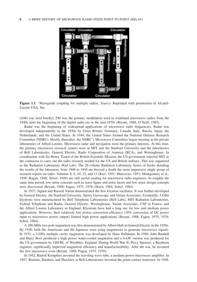
During World War II, most of the critical waveguide and coax elements had been developed. Waveg-uide flanges (and flange adapters) provided cost-effective coupling of waveguide, directional couplersprovided signal monitoring and sampling, filters provided frequency selectivity, and isolators and circula-tors provided two- and three-port directional routing of signals (Fig. 1.1) (Marcuvitz, 1951; Montgomeryet al., 1948; Ragan, 1948; Southworth, 1950).
In 1897, Braun invented the Cathode Ray Tube with magnetic deflection. Fleming invented the two-electrode “thermionic valve” vacuum tube rectifier in 1904. de Forest improved on Fleming’s rectifier byinventing the three-electrode “Audion” vacuum tube in 1906. In 1912, Colpitts invented the push–pullamplifier using the Audion. Meissner used the three-electrode (triode) tube to generate RF waves in1913. About the same time, other oscillators were developed by Armstrong, de Forest, Meissner, Franklin,Round, Colpitts, and Hartley. Colpitts developed a modulator circuit in 1914. In 1918, Armstrong inventedthe superheterodyne receiver that is commonly used today. In 1919, Barkhausen and Kurz used a triodeto generate radio frequencies as high as 10 GHz and Transradio, a subsidiary of Telefunken, introducedduplex radio transmission. Oscillators using coaxial line and waveguide (hollow cavities) were introducedin 1932 and 1935, respectively. Armstrong invented frequency modulation (FM) (Armstrong, 1936) in1935. With the exception of a short period in the early 1970s [when single-sideband amplitude modulation
6 A BRIEF HISTORY OF MICROWAVE RADIO FIXED POINT-TO-POINT (RELAY)
Figure 1.1 Waveguide coupling for multiple radios. Source: Reprinted with permission of Alcatel-Lucent USA, Inc.
(AM) was used briefly], FM was the primary modulation used in wideband microwave radios from the1940s until the beginning of the digital radio era in the mid-1970s (Bryant, 1988; O’Neill, 1985).
Radar was the beginning of widespread applications of microwave radio frequencies. Radar wasdeveloped independently in the 1930s by Great Britain, Germany, Canada, Italy, Russia, Japan, theNetherlands, and the United States. In 1940, the United States formed the National Defense ResearchCommittee (NDRC). Shortly thereafter, the NDRC’s Microwave Committee began meeting at the privatelaboratories of Alfred Loomis. Microwave radar and navigation were the primary interests. At this time,the primary microwave research centers were at MIT and the Stanford University and the laboratoriesof Bell Laboratories, General Electric, Radio Corporation of America (RCA), and Westinghouse. Incoordination with Sir Henry Tizard of the British Scientific Mission, the US government selected MIT asthe contractor to carry out the radio research needed for the US and British military. This was organizedas the Radiation Laboratory (Rad Lab). The 28-volume Radiation Laboratory Series of books detailingthe results of the laboratory from 1940 to 1945 are beyond a doubt the most impressive single group ofresearch reports on radio. Volumes 8, 9, 10, 12, and 13 (Kerr, 1951; Marcuvitz, 1951; Montgomery et al.,1948; Ragan, 1948; Silver, 1949) are still useful reading for microwave radio engineers. In roughly thesame time period, low noise concepts such as noise figure and noise factor and low noise design conceptswere discovered (Bryant, 1988; Fagen, 1975, 1978; Okwit, 1984; Sobol, 1984).
In 1937, Sigurd and Russell Varian demonstrated the first klystron oscillator. It was further developedby General Electric, the Stanford University, Sperry Gyroscope, and Varian Associates. Eventually, 3-GHzklystrons were manufactured by Bell Telephone Laboratories (Bell Labs), MIT Radiation Laboratories,Federal Telephone and Radio, General Electric, Westinghouse, Varian Associates, CSF in France, andthe Alfred Loomis Laboratory in England. Klystrons have had a long use for low and medium powerapplications. However, their relatively low power conversion efficiency (30% conversion of DC powerinput to microwave power output) limited high power applications (Bryant, 1988; Fagen, 1975, 1978;Sobol, 1984).
A 200-MHz two-pole magnetron was first demonstrated by Albert Hull at General Electric in the 1920s.By 1930, both the Americans and the Japanese were using magnetrons to generate microwave signals.In 1935, a 3-GHz multiple cavity magnetron was developed by Hans Hollmann. In 1940, John Randalland Harry Boot produced a high power water-cooled magnetron and a 6-kW version was produced forthe US government by GECRL of Wembley, England. During World War II, Percy Spencer, a Raytheonengineer, significantly improved magnetron efficiency and manufacturability. After the war, he inventedthe first microwave oven (Bryant, 1988; Fagen, 1975, 1978).
In 1942, Rudolf Kompfner invented the traveling wave tube, a medium power microwave amplifier. In1947, Brattain, Bardeen, and Shockley at Bell Laboratories invented the point-contact transistor. In 1948,
MICROWAVE TELECOMMUNICATIONS COMPANIES 7
they invented the junction transistor. The first n–p–n transistor was demonstrated in 1950. Townespublished the principle of the MASER (microwave amplification by stimulated emission of radiation)in 1951. In 1957, Esaki developed the germanium tunnel diode and Soulde described the LASER (lightamplification by stimulated emission of radiation). In 1959, Jack Kilby of Texas Instruments and RobertNoyce of Fairchild independently developed the integrated circuit. The two shared the 2000 Nobel Prize inPhysics for this achievement. In 1960, Khang and Atalla developed silicon–silicon dioxide field-inducedsurface devices [which led to metal–oxide–semiconductor field-effect transistors (MOS FETs)]. In 1961,Biard and Pittman of Texas Instruments invented gallium arsenide (GaAs) diodes. Today most microwavelow and medium power applications use solid-state devices such as galium arsenide field-effect transistors(GaAs FETs). In 1962, Holonyak invented the first practical visible light-emitting diode (LED). In 1975,Ray Pengelly and James Turner invented the Monolithic Microwave Integrated Circuit (MMIC), althoughthe concept had been mentioned in the early 1960s by Kilby. These devices were later further developedthrough support from the Defense Advanced Research Projects Agency (DARPA) (Bryant, 1988; Fagen,1975, 1978; Millman, 1983).
In 1963, the Institute of Electrical and Electronic Engineers was formed by the merger of the Instituteof Radio Engineers (IRE) and the American Institute of Electrical Engineers (AIEE) (Tarrant, 2001).
In 1909, Sommerfeld (1909) published his theoretical integral equation solution to free space radiowave propagation. This was the beginning of theoretical analysis of radio waves (Oliner, 1984). Inthe 1920s, Nyquist (1924, 1928) and Hartley (1928) published the first significant papers addressinginformation theory. In the 1920s, 1930s, and 1940s Kotel’nikov (1959), Nyquist, and Shannon developedthe theoretical concepts of sampled signals and the relationship between the time and frequency domains.In 1939, Philip Smith, at Bell Telephone’s Radio Research Lab in New Jersey, developed what is knownas the Smith chart (Smits, 1985), a circular chart that shows the entire universe of complex impedancesin one convenient circle. From the mid-1930s to the mid-1940s, considerable research was applied to(Norton, 1962). In 1944, 1945, and 1948, Rice (July 1944, 1948) published his mathematical analysis ofrandom noise with and without a sine wave. In 1943, North (1963) defined what became called MatchedFilters and Friis (1944) discovered the concept of noise figure. This work has been used extensively in theanalysis of microwave fading statistics. In the late 1940s, Shannon (1948, 1949, 1950) and Tuller (1949)published significant papers on information theory of communications. In 1949, Weiner (1949) publishedhis theory of linear filtering of signals in the presence of noise. About this same time he reported whathas become known as the Weiner–Hopf equation that defines the relationship between signals in thetime and frequency domains. In the 1950s, Cooley and Tukey developed the fast fourier transform (FFT)algorithm. Blackman and Tukey (1958) introduced the concept of signal power spectrum.
The Hamming (1950) and Reed–Muller (Muller, 1954; Reed, 1954) convolutional (Elias, 1955) andcyclic (Prange, 1957) codes were invented in the 1950s. Friis (1946) and Norton (1953) developedthe modern radio wave transmission loss formula. In the 1950s, Bullington (1947, 1950, 1957, 1977)was developing the fundamental characteristics of practical microwave propagation. About the same time,Norton et al. (1955) were expanding Rice’s work on the combination of constant and Rayleigh-distributedsignals. In the 1950s and 1960s, Medhurst, Middleton, and Rice were developing the theory of analogFM microwave transmission. In 1960, Kalman (1960) published his theory of linear filtering of signal inthe presence of noise and the Bose, Hocquenghem, Chaudhuri (BCH) (Bose and Ray-Chaudhuri, 1960;Hocquenghem, 1959), and Reed and Solomon (1960) coding were invented. In 1965, Wozencraft andJacobs introduced the concept of geometric representation of signals. This is the basis of “constellations”now popular in modulation theory. In 1967, Viterbi (1967) published the algorithm currently used formost digital radio demodulators. Ungerboeck (1982) invented trellis coded modulation in 1982. In 1993,Berrou et al. (1993a) invented Turbo Coding. In 1996, Gallagher’s (Gallagher, 1962) low density paritycodes (LDPCs) were rediscovered by MacKay (Kizer, 1990; MacKay and Neal, 1996).
1.2 MICROWAVE TELECOMMUNICATIONS COMPANIES
Ericsson was started in 1876 as a telephone repair workshop in downtown Stockholm. It eventually becamethe primary supplier of telephones and switchboards to Sweden’s first telecommunications operatingcompany, Allmanna Telefonaktiebolag.
8 A BRIEF HISTORY OF MICROWAVE RADIO FIXED POINT-TO-POINT (RELAY)
In 1897, Guglielmo Marconi formed the Wireless Telegraph and Signal Company (also known as theMarconi Company Limited, as well as the Wireless Telegraph Trading Signal Company). Marconi andhis company created the first commercial radio transmission equipment and services. English Electricacquired the Marconi Company in 1946. The company was sold to the General Electric Corporation in1987 and renamed the Marconi Electronic Systems. In 1999, most of the Marconi Electronic Systemsassets was sold to British Aerospace (BAE) and it became part of BAE Systems. However, GeneralElectric retained the Marconi name, Marconi Corporation, which it sold to Ericsson in 2006 (Bryant,1988; Sobol, 1984).
Alcatel-Lucent was created in 2006 when Alcatel acquired Lucent Technologies. Alcatel was startedin 1898 as Compagnie Generale d’Electricite. In 1991, it became Alcatel Alsthom. In 1998, it shortenedits name to Alcatel. ALCATEL stands for “ALsacienne de Constructions Atomiques, de TELecom-munications et d’Electronique” (Alsacian Company for Atomic, Telecommunication, and ElectronicConstruction). Over several years ITT, SEL, Thomson-CSF, Teletra, Network Transmission SystemsDivision (NTSD) of Rockwell International (including the former Collins Microwave Radio Division),Newbridge Networks, DSC Communications, Spatial Wireless, Xylan, Packet Engines, Assured Access,iMagicTV, TiMetra, and eDial. Lucent Technologies was formed in 1996 by AT&T when it spun off itsmanufacturing and research organizations (primarily Western Electric and Bell Labs). Lucent acquiredAscend Communications in 1999.
Alcatel-Lucent has three centers of microwave radio development and marketing: Velizy (southwestParis), France; Vimercate (northeastern Milan), Italy (the former Teletra); and Plano (north Dallas),Texas (the former Collins Microwave Division of Rockwell International). The Alcatel-Lucent NorthAmerican microwave radio facilities in Plano, Texas traces its roots to the Collins Radio Company,which was founded in 1933 by Arthur A. Collins in Cedar Rapids, Iowa. The Collins Radio MicrowaveRadio Division was founded in Richardson (north Dallas), Texas, in 1951. The first prototype of Collinscommercial microwave equipment was placed in service between Dallas and Irving, Texas, in the springof 1954. Later that year, the first Collins microwave radio system was sold to the California InterstateTelephone Company. By 1958, Collins was mass-producing microwave equipment and was providing theFAA (Federal Aviation Administration) with microwave systems providing communications and radarsignal remoting networks. In 1973, Collins radio merged into Rockwell International. The Texas basedCollins Microwave Radio Division ultimately became Rockwell’s NTSD. During the 1970s, this divisionwas the sole supplier of microwave radio equipment to the MCI (Microwave Communications, Inc.),with most of its other sales to the Bell operating companies. In 1976, NTSD introduced its first digitalmicrowave radio, the MDR-11, an 11-GHz multiline system delivered to Wisconsin Bell (Madison toEau Claire). In a parallel evolution, the Alcatel Network Systems’ Raleigh, North Carolina, facility wasoriginally operated by the ITT Corporation, which opened its first plant in 1958. From this facility, ITTfirst established its T1 spanline business in 1971, T3 fiber-optic transmission systems in 1979, and the firstcommercial single-mode fiber-optic transmission system in 1983. In 1987, ITT and Compagnie Generaled’Electricitie (CGE) of France agreed to a joint venture, creating Alcatel N.V.—the largest manufacturerof communications equipment in the world. Alcatel completed a buyout of ITT’s 30% interest in the springof 1992. The company was incorporated in the Netherlands, operated from Paris, and had its technicalcenter in Belgium. This organization also created the Alcatel Network Systems Company, which washeadquartered in Raleigh, North Carolina. In 1991, Alcatel purchased NTSD from Rockwell Internationaland combined it with Alcatel Network Systems Company to form the Alcatel Network Systems, Inc.,headquartered in Richardson, Texas. After the acquisition of DSC, the headquarters was moved to theformer DCS facilities in Plano, Texas. In addition to microwave radios, this facility develops and marketsfiber optics and digital cross-connect systems.
Founded in 1899 in Japan as the first US/Japanese joint venture with Western Electric Company,Nippon Electric (now NEC), headquartered in Tokyo, Japan, established itself as a technological leaderearly in its history by developing Japan’s telephone communications system. Recognizing the impactinformation processing would eventually have on the world community, NEC was one of the earliestentrants into the computer and semiconductor markets in the early 1950s. NEC also supported muchmicrowave research. NEC has also manufactured microwave radios since the early 1950s and introducedits first microwave radio product to the US market in the early 1970s. Later, NEC delivered its firstdigital microwave radio to the United States in the mid-1970s. The NEC Corporation of America’s RadioCommunications Systems Division (RCSD) is headquartered in Irving, Texas (Morita, 1960).