digital sound decoder - soundtraxx · in a soundtraxx digital sound decoder ... the decoder will...
TRANSCRIPT
Tsunami® SoundCar™ Digital Sound Decoder™
Technical ReferenceSoftware Release 1.03**
®
SoundCar™
Digital Sound Decoder
Rev.D 09/06/17
**Includes previous software versions.

NoticeThe information in this document is subject to change without notice.
SoundTraxx (Throttle Up!) shall not be liable for technical or editorial errors or omissions contained herein; nor for incidental or consequential damages resulting from the furnishing, performance or use of this material.
This document contains information protected by copyright. No part of this document may be photocopied or reproduced in any form without the prior written consent of Throttle Up! Corp.
Product names mentioned herein may be trademarks and/or registered trademarks of their respective companies.
SoundTraxx, Tsunami2, Econami, Tsunami, SoundTraxx DCC, Digital Sound Decoder, Dynamic Digital Exhaust, Auto-Exhaust, Hyperlight, Sound-Car, BeastBanter, and Intelligent Consisting are trademarks of Throttle Up! Corp.
Tsunami SoundCar Technical Reference Page 1
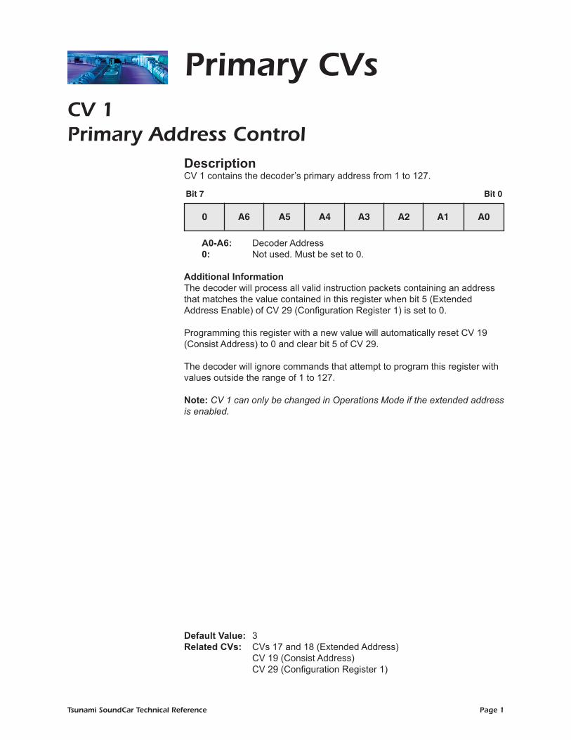
CV 1Primary Address Control Description CV 1 contains the decoder’s primary address from 1 to 127.
A0-A6: Decoder Address 0: Not used. Must be set to 0.
Additional InformationThe decoder will process all valid instruction packets containing an address that matches the value contained in this register when bit 5 (Extended Address Enable) of CV 29 (Configuration Register 1) is set to 0.
Programming this register with a new value will automatically reset CV 19 (Consist Address) to 0 and clear bit 5 of CV 29.
The decoder will ignore commands that attempt to program this register with values outside the range of 1 to 127.
Note: CV 1 can only be changed in Operations Mode if the extended address is enabled.
Default Value: 3Related CVs: CVs 17 and 18 (Extended Address) CV 19 (Consist Address) CV 29 (Configuration Register 1)
Bit 7 Bit 0
0 A6 A5 A4 A3 A2 A1 A0
Primary CVs

Tsunami SoundCar Technical Reference Page 2
Primary CVsCV 3 Baseline Acceleration Rate Description
CV 3 contains a value from 0 to 255 that sets the decoder’s acceleration rate.
D0-D7: Baseline Acceleration Rate
Additional Information The acceleration rate may be calculated as:
Seconds/Speed Step = CV 3 x 0.896 ÷ Number of Speed Steps
When CV 3 is set to 0, the speed-related sounds will respond almost instantly to increases in throttle setting, equivalent to no momentum. When set to 255, it will take the decoder sounds approximately 3.8 minutes to accelerate to full speed from a standing stop.
It is recommended that CV 3 be set to a non-zero value when operating the decoder in 14 or 28 speed-step mode, as the throttle will interpolate between speed steps during acceleration to produce a smoother overall response.
Note: For this CV, the value in a SoundCar decoder should match the value in a SoundTraxx Digital Sound Decoder equipped locomotive when in a consist.
Default Value: 0Related CVs: CV 4 (Baseline Deceleration Rate) CV 23 (Consist Acceleration Rate) CV 24 (Consist Deceleration Rate)
Bit 7 Bit 0
D7 D6 D5 D4 D3 D2 D1 D0
Tsunami SoundCar Technical Reference Page 3
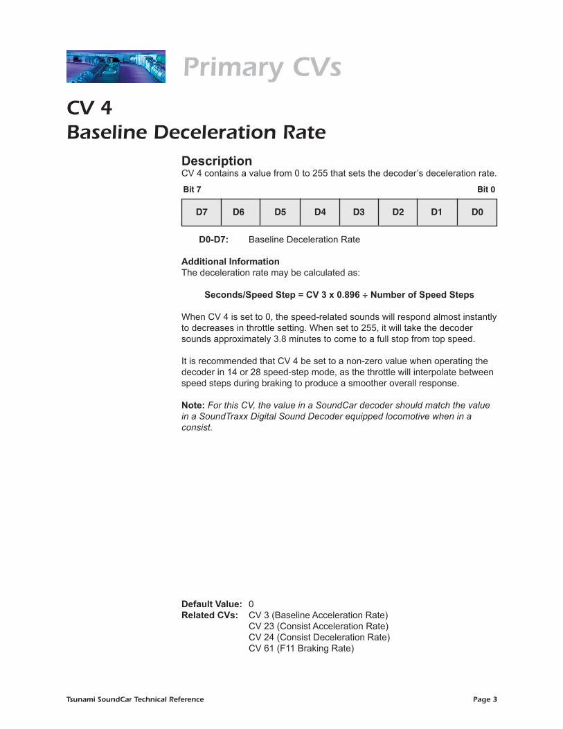
Primary CVsCV 4 Baseline Deceleration Rate Description CV 4 contains a value from 0 to 255 that sets the decoder’s deceleration rate.
D0-D7: Baseline Deceleration Rate
Additional Information The deceleration rate may be calculated as:
Seconds/Speed Step = CV 3 x 0.896 ÷ Number of Speed Steps
When CV 4 is set to 0, the speed-related sounds will respond almost instantly to decreases in throttle setting. When set to 255, it will take the decoder sounds approximately 3.8 minutes to come to a full stop from top speed.
It is recommended that CV 4 be set to a non-zero value when operating the decoder in 14 or 28 speed-step mode, as the throttle will interpolate between speed steps during braking to produce a smoother overall response.
Note: For this CV, the value in a SoundCar decoder should match the value in a SoundTraxx Digital Sound Decoder equipped locomotive when in a consist.
Default Value: 0Related CVs: CV 3 (Baseline Acceleration Rate) CV 23 (Consist Acceleration Rate) CV 24 (Consist Deceleration Rate) CV 61 (F11 Braking Rate)
Bit 7 Bit 0
D7 D6 D5 D4 D3 D2 D1 D0

Tsunami SoundCar Technical Reference Page 4
Primary CVs CV 7 Manufacturer Version ID (Read-Only)
Description CV 7 contains the 8-bit software identifier.
D0-D7: Version Code 69 = SoundCar Digital Sound Decoder, v1.0
Note: CV 7 is read-only and cannot be modified.
Default Value: 69
Bit 7 Bit 0
D7 D6 D5 D4 D3 D2 D1 D0

Tsunami SoundCar Technical Reference Page 5
Primary CVsCV 8 Manufacturer ID
DescriptionCV 8 contains the NMRA-issued Manufacturer ID code assigned to SoundTraxx/Throttle Up! (141).
Note: Writing a value of 8 to this CV will reset all CVs to their default values. All other write operations will be ignored.
Default Value: 141
Bit 7 Bit 0
1 0 0 0 1 1 0 1
Tsunami SoundCar Technical Reference Page 6
Primary CVsCV 11Packet Time-out Value
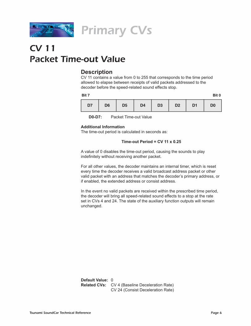
DescriptionCV 11 contains a value from 0 to 255 that corresponds to the time period allowed to elapse between receipts of valid packets addressed to the decoder before the speed-related sound effects stop.
D0-D7: Packet Time-out Value
Additional Information The time-out period is calculated in seconds as:
Time-out Period = CV 11 x 0.25
A value of 0 disables the time-out period, causing the sounds to play indefinitely without receiving another packet.
For all other values, the decoder maintains an internal timer, which is reset every time the decoder receives a valid broadcast address packet or other valid packet with an address that matches the decoder’s primary address, or if enabled, the extended address or consist address. In the event no valid packets are received within the prescribed time period, the decoder will bring all speed-related sound effects to a stop at the rate set in CVs 4 and 24. The state of the auxiliary function outputs will remain unchanged.
Default Value: 0Related CVs: CV 4 (Baseline Deceleration Rate) CV 24 (Consist Deceleration Rate)
Bit 7 Bit 0
D7 D6 D5 D4 D3 D2 D1 D0

Tsunami SoundCar Technical Reference Page 7
Primary CVsCV 12Power Source Conversion
DescriptionCV 12 defines the type of power source that the decoder should switch to whenever a DCC signal is not present and bit 2 (Alternate Powers Source Enable) of CV 29 (Configuration Register 1) is set.
D0: Alternate Power Source 0 = No alternate power source available 1 = Analog power supply 0: Not used. Must be set to 0.
Default Value: 1Related CV: CV 29 (Configuration Register 1)
Bit 7 Bit 0
0 0 0 0 0 0 0 D0
Tsunami SoundCar Technical Reference Page 8
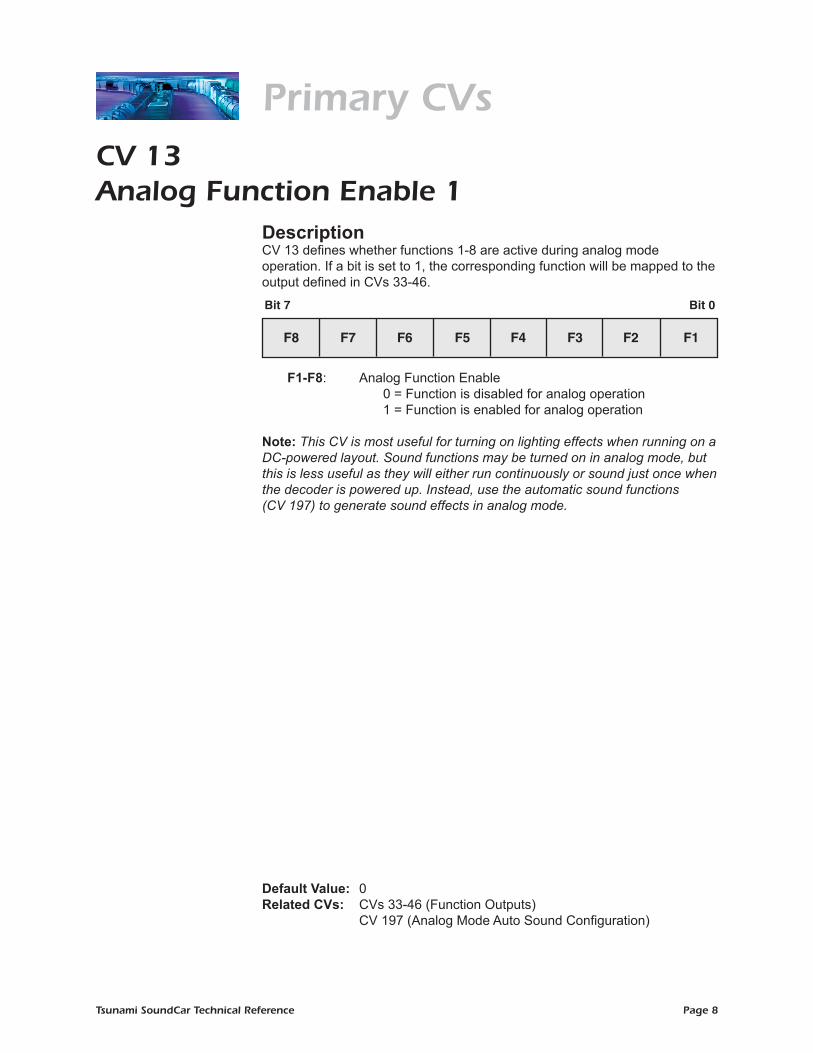
Primary CVsCV 13Analog Function Enable 1
DescriptionCV 13 defines whether functions 1-8 are active during analog mode operation. If a bit is set to 1, the corresponding function will be mapped to the output defined in CVs 33-46.
F1-F8: Analog Function Enable 0 = Function is disabled for analog operation 1 = Function is enabled for analog operation
Note: This CV is most useful for turning on lighting effects when running on a DC-powered layout. Sound functions may be turned on in analog mode, but this is less useful as they will either run continuously or sound just once when the decoder is powered up. Instead, use the automatic sound functions (CV 197) to generate sound effects in analog mode.
Default Value: 0Related CVs: CVs 33-46 (Function Outputs) CV 197 (Analog Mode Auto Sound Configuration)
Bit 7 Bit 0
F8 F7 F6 F5 F4 F3 F2 F1

Tsunami SoundCar Technical Reference Page 9
Primary CVsCV 14Analog Function Enable 2
DescriptionCV 14 defines whether functions 9-12 are active during analog mode operation. If a bit is set to 1, the corresponding function will be mapped to the output defined in CVs 33-46.
F0(f): F0 Forward Enable 0 = Function is disabled for analog operation 1 = Function is enabled for analog operation F0(r): F0 Reverse Enable 0 = Function is disabled for analog operation 1 = Function is enabled for analog operation
F9-F12: Analog Function Enable 0 = Function is disabled for analog operation 1 = Function is enabled for analog operation
0: Not used. Must be set to 0. Note: This CV is most useful for turning on lighting effects when running on a DC-powered layout. Sound functions may be turned on in analog mode, but this is less useful because they will either run continuously or sound only once when the decoder powers up. Instead, use the automatic sound functions (CV 197) to generate sound effects in analog mode.
Default Value: 3Related CVs: CVs 33-46 (Function Output Maps) CV 197 (Analog Mode Automatic Sound Configuration)
Bit 7 Bit 0
0 0 F12 F11 F10 F9 F0(r) F0(f)

Tsunami SoundCar Technical Reference Page 10
Primary CVsCV 15CV Unlock Code
DescriptionCV 15 is used for unlocking access to the decoder’s CVs.
D0-D2: CV Unlock Code
0: Reserved
Additional Information Entering a value from 0 to 7 into CV 15 determines the decoder’s lock status. CV 15 can be accessed regardless of the decoder’s lock status.
Locked State: If the value of CV 15 is not equal to the value of CV 16 (CV Lock ID), all CVs are locked. Read and write operations will be ignored.
Unlocked State: The decoder’s CVs can be accessed only when the value
of CV 15 is equal to the value of CV 16.
Note: Bit 0 (CV Lock Enable) of CV 30 (Error Information) must be set to 1 in order for the lock feature in CVs 15 and 16 to be used.
Default Value: 0Related CVs: CV 16 (CV Lock ID) CV 30 (Error Information)
Bit 7 Bit 0
0 0 0 0 0 D2 D1 D0

Tsunami SoundCar Technical Reference Page 11
Primary CVsCV 16CV Lock ID
DescriptionCV 16 is used in conjunction with CV 15 (CV Unlock Code) to determine the decoder’s lock status. CV 16 determines the lock code used to lock the decoder’s CVs.
ID0-ID2: CV Lock Code
0: Reserved
Additional Information Entering a value from 0 to 7 into CV 16 determines the decoder’s lock status.
CV 16 can be accessed regardless of the decoder’s lock status.
Locked State: If the value of CV 16 is not equal to the value of CV 15 (CV Unlock Code), all CVs are locked and all read and write operations will be ignored.
Unlocked State: The decoder’s CVs will only be accessible when the value of CV 15 is equal to the value of CV 16.
Note: Bit 0 (CV Lock Enable) of CV 30 (Error Information) must be set to 1 in order for the lock feature in CVs 15 and 16 to be used.
Default Value: 0Related CVs: CV 15 (CV Unlock Code) CV 30 (Error Information)
Bit 7 Bit 0
0 0 0 0 0 ID2 ID1 ID0
Tsunami SoundCar Technical Reference Page 12
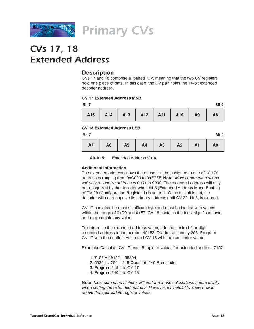
CVs 17, 18Extended Address
DescriptionCVs 17 and 18 comprise a “paired” CV, meaning that the two CV registers hold one piece of data. In this case, the CV pair holds the 14-bit extended decoder address.
CV 17 Extended Address MSB
CV 18 Extended Address LSB
A0-A15: Extended Address Value
Additional InformationThe extended address allows the decoder to be assigned to one of 10,179 addresses ranging from 0xC000 to 0xE7FF. Note: Most command stations will only recognize addresses 0001 to 9999. The extended address will only be recognized by the decoder when bit 5 (Extended Address Mode Enable) of CV 29 (Configuration Register 1) is set to 1. Once this bit is set, the decoder will not recognize its primary address until CV 29, bit 5, is cleared.
CV 17 contains the most significant byte and must be loaded with values within the range of 0xC0 and 0xE7. CV 18 contains the least significant byte and may contain any value.
To determine the extended address value, add the desired four-digit extended address to the number 49152. Divide the sum by 256. Program CV 17 with the quotient value and CV 18 with the remainder value.
Example: Calculate CV 17 and 18 register values for extended address 7152. 1. 7152 + 49152 = 56304 2. 56304 ÷ 256 = 219 Quotient; 240 Remainder 3. Program 219 into CV 17 4. Program 240 into CV 18
Note: Most command stations will perform these calculations automatically when setting the extended address. However, it’s helpful to know how to derive the appropriate register values.
Primary CVs
Bit 7 Bit 0
A15 A14 A13 A12 A11 A10 A9 A8
Bit 7 Bit 0
A7 A6 A5 A4 A3 A2 A1 A0

Tsunami SoundCar Technical Reference Page 13
Primary CVsBecause CVs 17 and 18 are a paired CV, programming order is important. Always write to CV 17 first, and then write to CV 18. The decoder will ignore commands that attempt to program these registers out of order or with values outside of the allowable range of 0xC000 to 0xE7FF.
These CVs may be changed in Service Mode at any time, but may only be changed in Operations Mode if CV 29, bit 5, is cleared (i.e., CV 1, Primary Address, is enabled).
Default Value: CV 17 = 192 CV 18 = 3 (Long Address 0003) Related CVs: CV 1 (Primary Address) CV 19 (Consist Address) CV 29 (Configuration Register 1)
Tsunami SoundCar Technical Reference Page 14
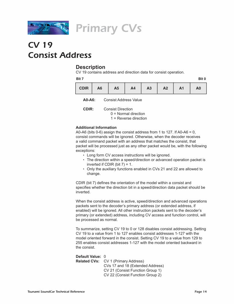
Primary CVsCV 19Consist Address
DescriptionCV 19 contains address and direction data for consist operation.
A0-A6: Consist Address Value
CDIR: Consist Direction 0 = Normal direction 1 = Reverse direction
Additional Information A0-A6 (bits 0-6) assign the consist address from 1 to 127. If A0-A6 = 0, consist commands will be ignored. Otherwise, when the decoder receives a valid command packet with an address that matches the consist, that packet will be processed just as any other packet would be, with the following exceptions:
• Long form CV access instructions will be ignored. • The direction within a speed/direction or advanced operation packet is
inverted if CDIR (bit 7) = 1. • Only the auxiliary functions enabled in CVs 21 and 22 are allowed to
change.
CDIR (bit 7) defines the orientation of the model within a consist and specifies whether the direction bit in a speed/direction data packet should be inverted. When the consist address is active, speed/direction and advanced operations packets sent to the decoder’s primary address (or extended address, if enabled) will be ignored. All other instruction packets sent to the decoder’s primary (or extended) address, including CV access and function control, will be processed as normal.
To summarize, setting CV 19 to 0 or 128 disables consist addressing. Setting CV 19 to a value from 1 to 127 enables consist addresses 1-127 with the model oriented forward in the consist. Setting CV 19 to a value from 129 to 255 enables consist addresses 1-127 with the model oriented backward in the consist.
Default Value: 0Related CVs: CV 1 (Primary Address) CVs 17 and 18 (Extended Address) CV 21 (Consist Function Group 1) CV 22 (Consist Function Group 2)
Bit 7 Bit 0
CDIR A6 A5 A4 A3 A2 A1 A0

Tsunami SoundCar Technical Reference Page 15
Primary CVsCV 21Consist Function Group 1
DescriptionCV 21 defines the Group 1 functions that may be controlled by packets sent to the decoder’s consist address, which is useful for differentiating the various engines and cars in a consist. Disabled functions may be controlled only from the decoder’s primary or extended address.
F1-F8: Consist Functions 1-8 Enable 0 = Function disabled in consist operation 1 = Function enabled in consist operation
Default Value: 128Related CVs: CV 19 (Consist Address) CV 22 (Consist Function Group 2)
Bit 7 Bit 0
F8 F7 F6 F5 F4 F3 F2 F1

Tsunami SoundCar Technical Reference Page 16
Primary CVsCV 22Consist Function Group 2
DescriptionThis CV defines the Group 2 functions that may be controlled by packets sent to the decoder’s consist address. Disabled functions may be controlled only from the decoder’s primary or extended address.
F0(f): Consist Function 0, Forward Enable 0 = Function disabled in consist operation 1 = Function enabled in consist operation
F0(r): Consist Function 0, Reverse Enable 0 = Function disabled in consist operation 1 = Function enabled in consist operation
F9-F12: Consist Functions 9-12 Enable 0 = Function disabled in consist operation 1 = Function enabled in consist operation
0: Not used. Must be set to 0.
Additional Information Among other things, this register allows you to differentiate headlight and backup light functions for the lead engine and other units in the consist.
Default Value: 16Related CVs: CV 19 (Consist Address) CV 21 (Consist Function Group 1)
Bit 7 Bit 0
0 0 F12 F11 F10 F9 F0(r) F0(f)

Tsunami SoundCar Technical Reference Page 17
Primary CVsCV 23Consist Acceleration Rate
DescriptionCV 23 contains a value from -127 to +127 that corresponds to the decoder’s consist acceleration offset.
D0-D6: Consist Acceleration Value
SIGN: Sign 0 = Positive value 1 = Negative value
Additional Information When the consist address is active, the consist acceleration rate is added to or subtracted from the decoder’s base acceleration rate (CV 3) depending on the Sign bit (bit 7). The acceleration is then calculated as:
Seconds/Speed Step = (CV 3 + CV 23) x 0.896 ÷ Number of Speed Steps
If the sum of CVs 3 and 23 is a negative value, then the acceleration rate is set to 0 (i.e., acceleration is instant). If the sum of CVs 3 and 23 exceeds 255, then the acceleration rate is set to the maximum value of 255.
CV 23 has no effect when the consist address (CV 19) is set to 0.
To summarize, a CV 23 value from 0 to 127 will increase the decoder’s base acceleration rate. Conversely, values from 129 to 255 will decrease the decoder’s base acceleration rate. A value of 128 is equivalent to a setting of 0 and will have no effect. Note: When operating Intelligent Consisting, it is best to leave this value at 0 unless all of the locomotives pulling the cars are set up using advanced consisting.
Default Value: 0Related CVs: CV 3 (Baseline Acceleration Rate) CV 4 (Baseline Deceleration Rate) CV 19 (Consist Address) CV 24 (Consist Deceleration Rate)
Bit 7 Bit 0
SIGN D6 D5 D4 D3 D2 D1 D0

Tsunami SoundCar Technical Reference Page 18
Primary CVsCV 24Consist Deceleration Rate
DescriptionCV 24 contains a value from -127 to +127, which corresponds to the decoder’s consist deceleration offset.
D0-D6: Consist Deceleration Value
SIGN: Sign 0 = Positive value 1 = Negative value
Additional Information When the consist address is active, the consist deceleration rate is added to or subtracted from the decoder’s baseline deceleration rate (CV 4) depending on the Sign bit (bit 7). The deceleration rate is then calculated as:
Seconds/Speed Step = (CV 4 + CV 24) x 0.896 ÷ Number of Speed Steps
If the sum of CVs 4 and 24 is negative, then the deceleration rate is set to 0 (i.e., braking is instant). If the sum of CVs 4 and 24 exceeds 255, then the deceleration rate is set to the maximum value of 255.
CV 24 has no effect when the consist address (CV 19) is set to 0.
To summarize, a CV 24 value from 0 to 127 will increase the decoder’s baseline deceleration rate. Conversely, values from 129 to 255 will decrease the decoder’s baseline deceleration rate. A value of 128 is equivalent to a setting of 0 and will have no effect. Note: When operating Intelligent Consisting, it is best to leave this value at 0 unless all of the locomotives pulling the cars are set up using advanced consisting.
Default Value: 0Related CVs: CV 3 (Baseline Acceleration Rate) CV 4 (Baseline Deceleration Rate) CV 19 (Consist Address) CV 23 (Consist Acceleration Rate)
Bit 7 Bit 0
SIGN D6 D5 D4 D3 D2 D1 D0

Tsunami SoundCar Technical Reference Page 19
Primary CVsCV 29Configuration Register 1
DescriptionCV 29 contains miscellaneous decoder configuration bits.
DIR: Direction 0 = Normal operation
1 = Direction bit in speed/direction instruction is inverted before processing
F0: F0 Location 0 = F0 state is controlled by bit 4 of speed/direction instruction (14 speed-step mode) 1 = F0 state is controlled by bit 4 of Function Group 1 (28 and 128 speed-step modes)
APS: Alternate Power Source Enable 0 = NMRA digital only 1 = Alternate power source enabled as set by CV 12
ACK: Advanced Acknowledgment Mode Enable (not used)
EAM: Extended Address Mode Enable 0 = Decoder responds to primary address in CV 1 1 = Decoder responds to extended address in CVs 17 and 18
MD: Multifunction Decoder (always reads as 0) 0: Not used. Must be set to 0. F0 (bit 1) should be cleared to 0 if you are using 14 speed-step mode. For 28 or 128 speed-step mode, bit 1 should be set to 1.
APS (bit 2) must be set to 1 in order to activate an alternate power mode as programmed into CV 12 (Power Source Conversion). To activate analog mode, CV 12 must be set to 1.
ACK (bit 3) will always read as 0 because the decoder does not support advanced acknowledgment.
Bit 7 Bit 0
MD 0 EAM 0 ACK APS F0 DIR

Tsunami SoundCar Technical Reference Page 20
Primary CVsEAM (bit 5) must be set to 1 in order to activate extended address capability. Note that once bit 5 is set, the decoder will respond to commands sent to the extended address only; commands to the primary address will be ignored. This can be a problem if you are using a command station that does not support extended addressing and bit 5 is accidentally programmed. In such a scenario, connect the decoder to a programming track to access CV 29 and clear bit 5.
Default Value: 2Related CVs: CV 12 (Alternate Power Source) CVs 17 and 18 (Extended Address)

Tsunami SoundCar Technical Reference Page 21
Primary CVsCV 30Error Information/Alternate Mode Selection
DescriptionThis CV contains manufacturer-defined error codes and provides feedback in the event an operational failure occurs within the decoder. It is also used to reconfigure the decoder for non-NMRA compliant options.
CVLCKE: CV Lock Enable 0 = Normal operation 1 = Enables CV lock as set in CVs 15 and 16
CVCLR: CV Clear 0 = Normal operation 1 = All CVs will be reset to default values at next
power cycle, regardless of other active bits GRP23: Function Group 2 and 3 Exchange
0 = System normal, decoder processes Group 2 and 3 function commands according to the NMRA Standard 1 = Function Group 2 (F5-F8) assignments are swapped with Group 3 (F9-F12) assignments
0: Not used. Must be set to 0.
Default Value: 0
Related CVs: CV 15 (CV Unlock Code) CV 16 (CV Lock ID)
Bit 7 Bit 0
0 0 0 0 0 GRP23 CVCLR CVLCKE
Tsunami SoundCar Technical Reference Page 22
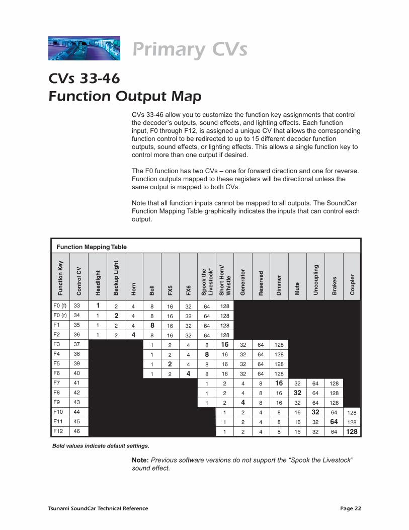
Primary CVsCVs 33-46Function Output Map
CVs 33-46 allow you to customize the function key assignments that control the decoder’s outputs, sound effects, and lighting effects. Each function input, F0 through F12, is assigned a unique CV that allows the corresponding function control to be redirected to up to 15 different decoder function outputs, sound effects, or lighting effects. This allows a single function key to control more than one output if desired.
The F0 function has two CVs – one for forward direction and one for reverse. Function outputs mapped to these registers will be directional unless the same output is mapped to both CVs.
Note that all function inputs cannot be mapped to all outputs. The SoundCar Function Mapping Table graphically indicates the inputs that can control each output.
Note: Previous software versions do not support the “Spook the Livestock” sound effect.
33
34
35
36
37
38
39
40
41
42
43
44
45
46
128
128
128
128
1616
16
16
2
2
2
1
1
1
64
64
64
64
8
88
8
1
1
1
32
32
32
32
4
4
4
4
X
16
16
16
16
2
2
2 2
X
8
8
8 8
1
1
1
1
X
4
4
4
4
2
2 2
2
1 1
1
1
32
32
32
32
4
4
42
2
2
64
64
64
64
8
8
8
4
4
4
128
128
128
128
16 16
16
8
8
8
X
X
X
32
32 32
16
16
16
64
64
64
32 32
32
128
128
128
64
64 64
128
128
128
Co
ntr
ol C
V
F0 (f)
F0 (r)
F1
F2
F3
F4
F5
F6
F7
F8
F9
F10
F11
F12
Fu
nct
ion
Key
Hea
dlig
ht
Bac
kup
Lig
ht
Ho
rn
Bel
l
Sh
ort
Ho
rn/
Wh
istl
e
Gen
erat
or
Res
erve
d
FX
5
Sp
oo
k th
e L
ives
tock
*
FX
6
Function Mapping Table
Dim
mer
Mu
te
Un
cou
plin
g
Bra
kes
Co
up
ler
Bold values indicate default settings.

Tsunami SoundCar Technical Reference Page 23
Primary CVsCV 33F0(f) Output Location
DescriptionCV 33 maps the F0(f) function to any of eight auxiliary decoder outputs as defined by a 1 in the corresponding bit position.
HL: Headlight Output 0 = Output is unaffected by F0(f) 1 = Output is activated when F0(f) is on
BL: Backup Light Output 0 = Output is unaffected by F0(f) 1 = Output is activated when F0(f) is on
HORN: Airhorn/Whistle Sound Effect 0 = Sound is unaffected by F0(f) 1 = Sound is activated when F0(f) is on
BELL: Bell Sound Effect 0 = Sound is unaffected by F0(f) 1 = Sound is activated when F0(f) is on
FX5: Effect 1 Output 0 = Output is unaffected by F0(f) 1 = Output is activated when F0(f) is on
FX6: Effect 2 Output 0 = Output is unaffected by F0(f) 1 = Output is activated when F0(f) is on SLS: Spook the Livestock * 0 = Sound is unaffected by F0(f) 1 = Sound is activated when F0(f) is on
SHH: Short Horn/Whistle Sound Effect 0 = Sound is unaffected by F0(f) 1 = Sound is activated when F0(f) is on
Note: Previous software versions do not support the “Spook the Livestock” sound effect.
Default Value: 1
Related CVs: CVs 34-46 (Function Output Map)
Bit 7
Steam:
Bit 0
SHW DYN FX6 FX5 BELL WH BL HL
Bit 7
Diesel:
Bit 0
SHH SLS FX6 FX5 BELL HORN BL HL
Tsunami SoundCar Technical Reference Page 24
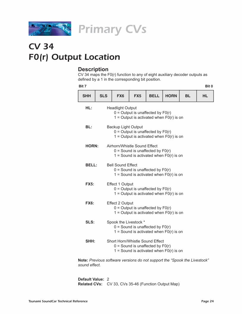
Primary CVsCV 34F0(r) Output Location
DescriptionCV 34 maps the F0(r) function to any of eight auxiliary decoder outputs as defined by a 1 in the corresponding bit position.
HL: Headlight Output 0 = Output is unaffected by F0(r) 1 = Output is activated when F0(r) is on
BL: Backup Light Output 0 = Output is unaffected by F0(r) 1 = Output is activated when F0(r) is on
HORN: Airhorn/Whistle Sound Effect 0 = Sound is unaffected by F0(r) 1 = Sound is activated when F0(r) is on
BELL: Bell Sound Effect 0 = Sound is unaffected by F0(r) 1 = Sound is activated when F0(r) is on
FX5: Effect 1 Output 0 = Output is unaffected by F0(r) 1 = Output is activated when F0(r) is on
FX6: Effect 2 Output 0 = Output is unaffected by F0(r) 1 = Output is activated when F0(r) is on SLS: Spook the Livestock * 0 = Sound is unaffected by F0(r) 1 = Sound is activated when F0(r) is on
SHH: Short Horn/Whistle Sound Effect 0 = Sound is unaffected by F0(r) 1 = Sound is activated when F0(r) is on
Note: Previous software versions do not support the “Spook the Livestock” sound effect.
Default Value: 2
Related CVs: CV 33, CVs 35-46 (Function Output Map)
Bit 7
Steam:
Bit 0
SHW DYN FX6 FX5 BELL WH BL HL
Bit 7
Diesel:
Bit 0
SHH SLS FX6 FX5 BELL HORN BL HL

Tsunami SoundCar Technical Reference Page 25
Primary CVsCV 35F1 Output Location
Description
CV 35 maps the F1 function to any of eight auxiliary decoder outputs as defined by a 1 in the corresponding bit position.
HL: Headlight Output 0 = Output is unaffected by F1 1 = Output is activated when F1 is on
BL: Backup Light Output 0 = Output is unaffected by F1 1 = Output is activated when F1 is on
HORN: Airhorn/Whistle Sound Effect 0 = Sound is unaffected by F1 1 = Sound is activated when F1 is on
BELL: Bell Sound Effect 0 = Sound is unaffected by F1 1 = Sound is activated when F1 is on
FX5: Effect 1 Output 0 = Output is unaffected by F1 1 = Output is activated when F1 is on
FX6: Effect 2 Output 0 = Output is unaffected by F1 1 = Output is activated when F1 is on
SLS: Spook the Livestock * 0 = Sound is unaffected by F1 1 = Sound is activated when F1 is on
SHH: Short Horn/Whistle Sound Effect 0 = Sound is unaffected by F1 1 = Sound is activated when F1 is on
Note: Previous software versions do not support the “Spook the Livestock” sound effect.
Default Value: 8 Related CVs: CVs 33-34, 36-46 (Function Output Map)
Bit 7
Steam:
Bit 0
SHW DYN FX6 FX5 BELL WH BL HL
Bit 7
Diesel:
Bit 0
SHH SLS FX6 FX5 BELL HORN BL HL

Tsunami SoundCar Technical Reference Page 26
Primary CVsCV 36F2 Output Location
DescriptionCV 36 maps the F2 function to any of eight auxiliary decoder outputs as defined by a 1 in the corresponding bit position.
HL: Headlight Output 0 = Output is unaffected by F2 1 = Output is activated when F2 is on
BL: Backup Light Output 0 = Output is unaffected by F2 1 = Output is activated when F2 is on
HORN: Airhorn/Whistle Sound Effect 0 = Sound is unaffected by F2 1 = Sound is activated when F2 is on
BELL: Bell Sound Effect 0 = Sound is unaffected by F2 1 = Sound is activated when F2 is on
FX5: Effect 1 Output 0 = Output is unaffected by F2 1 = Output is activated when F2 is on
FX6: Effect 2 Output 0 = Output is unaffected by F2 1 = Output is activated when F2 is on
SLS: Spook the Livestock * 0 = Sound is unaffected by F2 1 = Sound is activated when F2 is on
SHH: Short Horn/Whistle Sound Effect 0 = Sound is unaffected by F2 1 = Sound is activated when F2 is on
Note: Previous software versions do not support the “Spook the Livestock” sound effect.
Default Value: 4
Related CVs: CVs 33-35, 37-46 (Function Output Map)
Bit 7
Steam:
Bit 0
SHW DYN FX6 FX5 BELL WH BL HL
Bit 7
Diesel:
Bit 0
SHH SLS FX6 FX5 BELL HORN BL HL

Tsunami SoundCar Technical Reference Page 27
CV 37F3 Output Location
DescriptionCV 37 maps the F3 function to any of eight auxiliary decoder outputs as defined by a 1 in the corresponding bit position.
BELL: Bell Sound Effect 0 = Sound is unaffected by F3 1 = Sound is activated when F3 is on
FX5: Effect 1 Output 0 = Output is unaffected by F3 1 = Output is activated when F3 is on
FX6: Effect 2 Output 0 = Output is unaffected by F3 1 = Output is activated when F3 is on
SLS: Spook the Livestock * 0 = Sound is unaffected by F3 1 = Sound is activated when F3 is on
SHH: Short Horn/Whistle Sound Effect 0 = Sound is unaffected by F3 1 = Sound is activated when F3 is on
GEN: Generator Sound Effect 0 = Sound is unaffected by F3 1 = Sound is activated when F3 is on
DIM: Headlight Dimmer Function 0 = Output is unaffected by F3 1 = Output is activated when F3 is on
0: Not used. Must be set to 0.
Note: Previous software versions do not support the “Spook the Livestock” sound effect.
Default Value: 16
Related CVs: CVs 33-36, 38-46 (Function Output Map)
Bit 7
Steam:
Bit 0
DIM WS STM SHW DYN FX6 FX5 BEL
Bit 7
Diesel:
Bit 0
DIM 0 GEN SHH SLS FX6 FX5 BELL
Primary CVs

Tsunami SoundCar Technical Reference Page 28
CV 38F4 Output Location
DescriptionCV 38 maps the F4 function to any of eight auxiliary decoder outputs as defined by a 1 in the corresponding bit position.
BELL: Bell Sound Effect 0 = Sound is unaffected by F4 1 = Sound is activated when F4 is on
FX5: Effect 1 Output 0 = Output is unaffected by F4 1 = Output is activated when F4 is on
FX6: Effect 2 Output 0 = Output is unaffected by F4 1 = Output is activated when F4 is on
SLS: Spook the Livestock * 0 = Sound is unaffected by F4 1 = Sound is activated when F4 is on
SHH: Short Horn/Whistle Sound Effect 0 = Sound is unaffected by F4 1 = Sound is activated when F4 is on
GEN: Generator Sound Effect 0 = Sound is unaffected by F4 1 = Sound is activated when F4 is on
DIM: Headlight Dimmer Function 0 = Output is unaffected by F4 1 = Output is activated when F4 is on
0: Not used. Must be set to 0.
Note: Previous software versions do not support the “Spook the Livestock” sound effect.
Default Value: 0
Related CVs: CVs 33-37, 39-46 (Function Output Map)
Bit 7
Steam:
Bit 0
DIM WS STM SHW DYN FX6 FX5 BEL
Bit 7
Diesel:
Bit 0
DIM 0 GEN SHH SLS FX6 FX5 BELL
Primary CVs

Tsunami SoundCar Technical Reference Page 29
CV 39F5 Output Location
DescriptionCV 39 maps the F5 function to any of eight auxiliary decoder outputs as defined by a 1 in the corresponding bit position.
BELL: Bell Sound Effect 0 = Sound is unaffected by F5 1 = Sound is activated when F5 is on
FX5: Effect 1 Output 0 = Output is unaffected by F5 1 = Output is activated when F5 is on
FX6: Effect 2 Output 0 = Output is unaffected by F5 1 = Output is activated when F5 is on
SLS: Spook the Livestock * 0 = Sound is unaffected by F5 1 = Sound is activated when F5 is on
SHH: Short Horn/Whistle Sound Effect 0 = Sound is unaffected by F5 1 = Sound is activated when F5 is on
GEN: Generator Sound Effect 0 = Sound is unaffected by F5 1 = Sound is activated when F5 is on
DIM: Headlight Dimmer Function 0 = Output is unaffected by F5 1 = Output is activated when F5 is on
0: Not used. Must be set to 0.
Note: Previous software versions do not support the “Spook the Livestock” sound effect.
Default Value: 2
Related CVs: CVs 33-38, 40-46 (Function Output Map)
Bit 7
Steam:
Bit 0
DIM WS STM SHW DYN FX6 FX5 BEL
Bit 7
Diesel:
Bit 0
DIM 0 GEN SHH SLS FX6 FX5 BELL
Primary CVs

Tsunami SoundCar Technical Reference Page 30
CV 40F6 Output Location
DescriptionCV 40 maps the F6 function to any of eight auxiliary decoder outputs as defined by a 1 in the corresponding bit position.
BELL: Bell Sound Effect 0 = Sound is unaffected by F6 1 = Sound is activated when F6 is on
FX5: Effect 1 Output 0 = Output is unaffected by F6 1 = Output is activated when F6 is on
FX6: Effect 2 Output 0 = Output is unaffected by F6 1 = Output is activated when F6 is on
SLS: Spook the Livestock * 0 = Sound is unaffected by F6 1 = Sound is activated when F6 is on
SHH: Short Horn/Whistle Sound Effect 0 = Sound is unaffected by F6 1 = Sound is activated when F6 is on
GEN: Generator Sound Effect 0 = Sound is unaffected by F6 1 = Sound is activated when F6 is on
DIM: Headlight Dimmer Function 0 = Output is unaffected by F6 1 = Output is activated when F6 is on
0: Not used. Must be set to 0.
Note: Previous software versions do not support the “Spook the Livestock” sound effect.
Default Value: 4
Related CVs: CVs 33-39, 41-46 (Function Output Map)
Bit 7
Steam:
Bit 0
DIM WS STM SHW DYN FX6 FX5 BEL
Bit 7
Diesel:
Bit 0
DIM 0 GEN SHH SLS FX6 FX5 BELL
Primary CVs

Tsunami SoundCar Technical Reference Page 31
CV 41F7 Output Location
DescriptionCV 41 maps the F7 function to any of eight auxiliary decoder outputs as defined by a 1 in the corresponding bit position.
SLS: Spook the Livestock * 0 = Sound is unaffected by F7 1 = Sound is activated when F7 is on
SHH: Short Horn/Whistle Sound Effect 0 = Sound is unaffected by F7 1 = Sound is activated when F7 is on
GEN: Generator Sound Effect 0 = Sound is unaffected by F7 1 = Sound is activated when F7 is on
DIM: Headlight Dimmer Function 0 = Output is unaffected by F7 1 = Output is activated when F7 is on
MUT: Audio Mute 0 = Output is unaffected by F7 1 = Output is activated when F7 is on
UNCPL: Uncoupling Sound Effects 0 = Sound is unaffected by F7 1 = Sound is activated when F7 is on
BRK: Brake Squeal/Brake Release Sound Effects 0 = Sound is unaffected by F7 1 = Sound is activated when F7 is on
0: Not used. Must be set to 0.
Note: Previous software versions do not support the “Spook the Livestock” sound effect.
Default Value: 16
Related CVs: CVs 33-40, 42-46 (Function Output Map)
Bit 7
Steam:
Bit 0
BRK INJ MUT DIM WS STM SHW DYN
Bit 7
Diesel:
Bit 0
BRK UNCPL MUT DIM 0 GEN SHH SLS
Primary CVs

Tsunami SoundCar Technical Reference Page 32
CV 42F8 Output Location
DescriptionCV 42 maps the F8 function to any of eight auxiliary decoder outputs as defined by a 1 in the corresponding bit position.
SLS: Spook the Livestock * 0 = Sound is unaffected by F8 1 = Sound is activated when F8 is on
SHH: Short Horn/Whistle Sound Effect 0 = Sound is unaffected by F8 1 = Sound is activated when F8 is on
GEN: Generator Sound Effect 0 = Sound is unaffected by F8 1 = Sound is activated when F8 is on
DIM: Headlight Dimmer Function 0 = Output is unaffected by F8 1 = Output is activated when F8 is on
MUT: Audio Mute 0 = Output is unaffected by F8 1 = Output is activated when F8 is on
UNCPL: Uncoupling Sound Effects 0 = Sound is unaffected by F8 1 = Sound is activated when F8 is on
BRK: Brake Squeal/Brake Release Sound Effects 0 = Sound is unaffected by F8 1 = Sound is activated when F8 is on
0: Not used. Must be set to 0.
Note: Previous software versions do not support the “Spook the Livestock”
sound effect.
Default Value: 32
Related CVs: CVs 33-41, 43-46 (Function Output Map)
Bit 7
Steam:
Bit 0
BRK INJ MUT DIM WS STM SHW DYN
Bit 7
Diesel:
Bit 0
BRK UNCPL MUT DIM 0 GEN SHH SLS
Primary CVs
Tsunami SoundCar Technical Reference Page 33
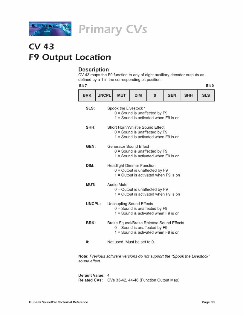
CV 43F9 Output Location
DescriptionCV 43 maps the F9 function to any of eight auxiliary decoder outputs as defined by a 1 in the corresponding bit position.
SLS: Spook the Livestock * 0 = Sound is unaffected by F9 1 = Sound is activated when F9 is on
SHH: Short Horn/Whistle Sound Effect 0 = Sound is unaffected by F9 1 = Sound is activated when F9 is on
GEN: Generator Sound Effect 0 = Sound is unaffected by F9 1 = Sound is activated when F9 is on
DIM: Headlight Dimmer Function 0 = Output is unaffected by F9 1 = Output is activated when F9 is on
MUT: Audio Mute 0 = Output is unaffected by F9 1 = Output is activated when F9 is on
UNCPL: Uncoupling Sound Effects 0 = Sound is unaffected by F9 1 = Sound is activated when F9 is on
BRK: Brake Squeal/Brake Release Sound Effects 0 = Sound is unaffected by F9 1 = Sound is activated when F9 is on
0: Not used. Must be set to 0.
Note: Previous software versions do not support the “Spook the Livestock” sound effect.
Default Value: 4
Related CVs: CVs 33-42, 44-46 (Function Output Map)
Bit 7
Steam:
Bit 0
BRK INJ MUT DIM WS STM SHW DYN
Bit 7
Diesel:
Bit 0
BRK UNCPL MUT DIM 0 GEN SHH SLS
Primary CVs
Tsunami SoundCar Technical Reference Page 34
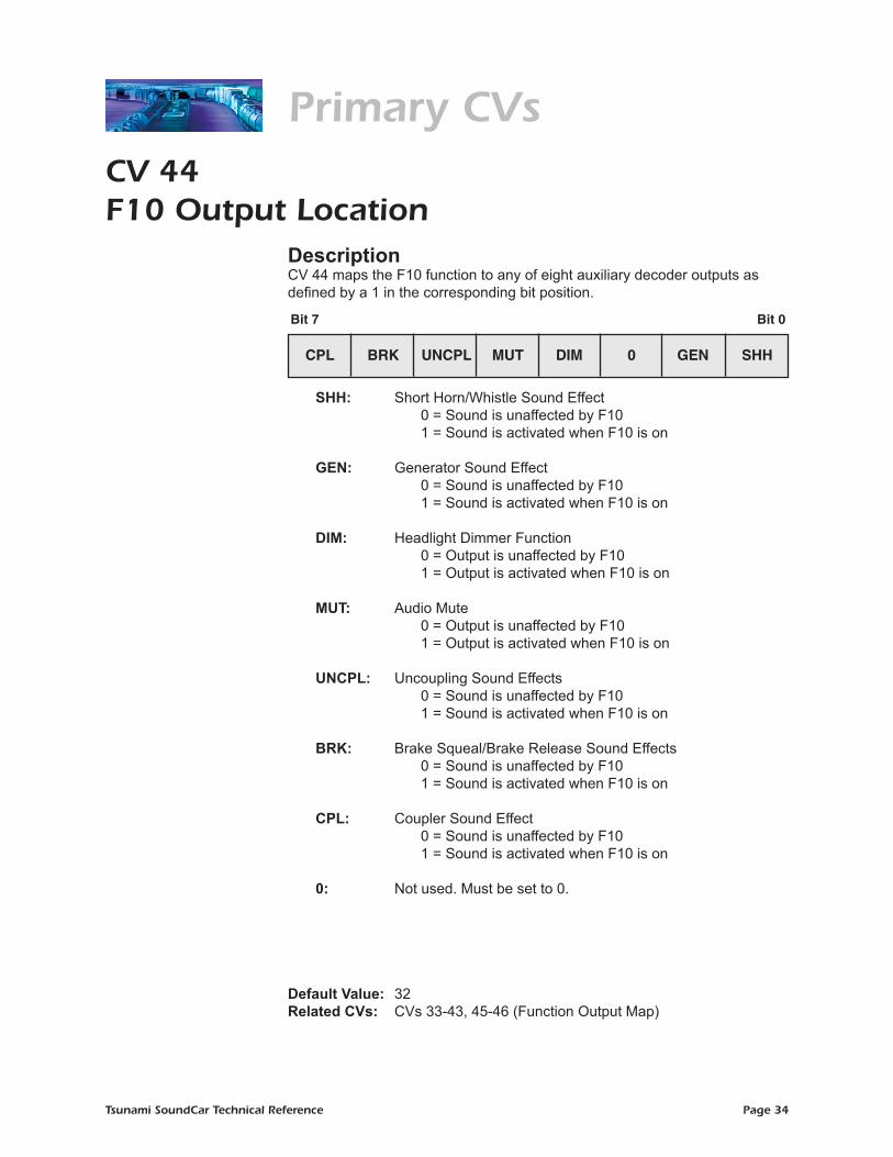
CV 44F10 Output Location
DescriptionCV 44 maps the F10 function to any of eight auxiliary decoder outputs as defined by a 1 in the corresponding bit position.
SHH: Short Horn/Whistle Sound Effect 0 = Sound is unaffected by F10 1 = Sound is activated when F10 is on
GEN: Generator Sound Effect 0 = Sound is unaffected by F10 1 = Sound is activated when F10 is on
DIM: Headlight Dimmer Function 0 = Output is unaffected by F10 1 = Output is activated when F10 is on
MUT: Audio Mute 0 = Output is unaffected by F10 1 = Output is activated when F10 is on
UNCPL: Uncoupling Sound Effects 0 = Sound is unaffected by F10 1 = Sound is activated when F10 is on
BRK: Brake Squeal/Brake Release Sound Effects 0 = Sound is unaffected by F10 1 = Sound is activated when F10 is on
CPL: Coupler Sound Effect 0 = Sound is unaffected by F10 1 = Sound is activated when F10 is on
0: Not used. Must be set to 0.
Default Value: 32
Related CVs: CVs 33-43, 45-46 (Function Output Map)
Bit 7
Steam:
Bit 0
CPL BRK INJ MUT DIM WS STM SHW
Bit 7
Diesel:
Bit 0
CPL BRK UNCPL MUT DIM 0 GEN SHH
Primary CVs
Tsunami SoundCar Technical Reference Page 35
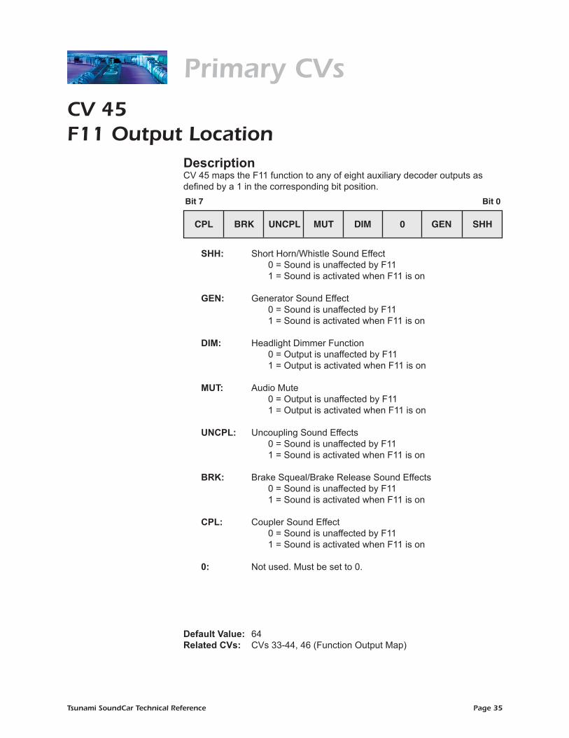
CV 45F11 Output Location
DescriptionCV 45 maps the F11 function to any of eight auxiliary decoder outputs as defined by a 1 in the corresponding bit position.
SHH: Short Horn/Whistle Sound Effect 0 = Sound is unaffected by F11 1 = Sound is activated when F11 is on
GEN: Generator Sound Effect 0 = Sound is unaffected by F11 1 = Sound is activated when F11 is on
DIM: Headlight Dimmer Function 0 = Output is unaffected by F11 1 = Output is activated when F11 is on
MUT: Audio Mute 0 = Output is unaffected by F11 1 = Output is activated when F11 is on
UNCPL: Uncoupling Sound Effects 0 = Sound is unaffected by F11 1 = Sound is activated when F11 is on
BRK: Brake Squeal/Brake Release Sound Effects 0 = Sound is unaffected by F11 1 = Sound is activated when F11 is on
CPL: Coupler Sound Effect 0 = Sound is unaffected by F11 1 = Sound is activated when F11 is on
0: Not used. Must be set to 0.
Default Value: 64
Related CVs: CVs 33-44, 46 (Function Output Map)
Primary CVsBit 7
Steam:
Bit 0
CPL BRK INJ MUT DIM WS STM SHW
Bit 7
Diesel:
Bit 0
CPL BRK UNCPL MUT DIM 0 GEN SHH

Tsunami SoundCar Technical Reference Page 36
CV 46F12 Output Location
DescriptionCV 46 maps the F12 function to any of eight auxiliary decoder outputs as defined by a 1 in the corresponding bit position.
SHH: Short Horn/Whistle Sound Effect 0 = Sound is unaffected by F12 1 = Sound is activated when F12 is on GEN: Generator Sound Effect 0 = Sound is unaffected by F12 1 = Sound is activated when F12 is on
DIM: Headlight Dimmer Function 0 = Output is unaffected by F12 1 = Output is activated when F12 is on
MUT: Audio Mute 0 = Output is unaffected by F12 1 = Output is activated when F12 is on
UNCPL: Uncoupling Sound Effects 0 = Sound is unaffected by F12 1 = Sound is activated when F12 is on
BRK: Brake Squeal/Brake Release Sound Effects 0 = Sound is unaffected by F12 1 = Sound is activated when F12 is on
CPL: Coupler Sound Effect 0 = Sound is unaffected by F12 1 = Sound is activated when F12 is on
0: Not used. Must be set to 0.
Default Value: 128
Related CVs: CVs 33-45 (Function Output Map)
Primary CVs
Bit 7
Steam:
Bit 0
CPL BRK INJ MUT DIM WS STM SHW
Bit 7
Diesel:
Bit 0
CPL BRK UNCPL MUT DIM 0 GEN SHH

Tsunami SoundCar Technical Reference Page 37
CVs 49-52Hyperlight Effect Select
DescriptionCVs 49-52 are used to set Hyperlight lighting effects and associated control modes for their respective outputs.
CV 49, Headlight Effect Select CV 50, Backup Light Effect Select CV 51, FX5 Effect Select CV 52, FX6 Effect Select
EF0-EF3: Effect Type Select 0 = On/off output 1 = Rule 17 dimmable headlight 2 = Mars Light 3 = Pyle-National Gyralite 4 = Oscillating headlight 5 = Single-flash strobe 6 = Double-flash strobe 7 = Western-Cullen D312 rotary beacon 8 = Prime Stratolite 9 = Type I ditch light 10 = Type II ditch light 11 = Flashing rear-end device (FRED) 12 = Engine exhaust flicker 13 = Firebox flicker 14 = Reserved 15 = Dyno-light
Rule 17 dimmable headlight – This function output is normally an on/off output. When it is on, the output level will be reduced by approximately 60% when the dimmer function is activated.
Mars Light – This effect simulates the sweeping figure-8 pattern of this popular warning beacon.
Pyle-National Gyralite – The Gyralite is similar to the Mars Light, but generates a slow, wide-sweeping elliptical headlight pattern.
Oscillating headlights – Similar in appearance to the common twin-sealed-beam headlight, the oscillating headlight uses a moving reflector to sweep the headlight beam in a tight circular motion.
Lighting Effect CVs
Bit 7 Bit 0
LED R17 XING PHSE EF3 EF2 EF1 EF0

Tsunami SoundCar Technical Reference Page 38
Single- and double-flash strobes – The strobe effect simulates the white-hot burst of light associated with a xenon strobe.
Western-Cullen D312 rotary beacon – This effect provides a spectacular rendition of the revolving reflector and bulb assembly found atop many diesels from the 60s and 70s.
Prime Stratolite – The Stratolite is a new version of the rotary beacon, with the prototype consisting of four individual lamps arranged in a circular pattern, which electronically flash in a clockwise direction. The Stratolite flashes in a mechanical “stepped” fashion, opposed to the smooth motion of the rotary beacon.
Type I and Type II ditch lights – These operate identically; however, if Grade Crossing Logic is enabled, the Type I ditch light will revert to a steady “on” state when it is not flashing, whereas the Type II lights will turn off.
Flashing rear-end device (FRED) – Also known as an end-of-train device, this red flashing marker light is mounted on the coupler of the rear car or on the back of the caboose to warn following trains.
Exhaust flicker – This effect produces a random flicker with an intensity that increases with the throttle speed. The most realistic effect can be achieved by placing a red or orange lamp under the model’s exhaust port, and out of direct view. As the speed steps ramp up, the effect will glow brighter, imitating unmuffled exhaust gases and sparks. Use this effect in power generator cars.
Firebox flicker – This effect produces a random flicker that resembles a burning fire and can be used by placing a lamp in the caboose to simulate a wood-burning stove. The effect is improved when two bulbs are used (one yellow, the other red or orange), each connected to a separate function output.
Dyno-light – This effect for steam locomotives synchronizes the lamp brightness to the “output” of the dynamo so that the lamp brightness gradually increases as the dynamo builds up speed. For diesel locomotives, the lights will fade on and off to simulate the heating and cooling of the bulb filaments.
PHSE: Phase Select 0 = Phase A 1 = Phase B
Phase Select (bit 4) – This bit alters the timing of the lighting effect so that it is 180 degrees out-of-phase with other lighting effects. This allows you to have two lighting effects blinking back and forth. Set one effect to Phase A and the other to Phase B.
Lighting Effect CVs
Tsunami SoundCar Technical Reference Page 39
XING: Grade Crossing Logic Enable 0 = Grade Crossing Logic disabled
1 = Grade Crossing Logic enabled when horn function is on Grade Crossing Logic (bit 5) – This bit causes the lighting effect to activate only when the horn/whistle is sounded (and the corresponding lighting function key is on). This can be used to create prototypical scenarios such as causing the ditch lights to flash at a grade crossing. Grade Crossing Logic can be used with nearly all of the Hyperlight effects without affecting the on/off, dimmable headlight, Dyno-light, FRED, engine exhaust, or firebox flicker effects. Other effects will either turn off (e.g., strobes and beacons) or revert to a steady “on” state (e.g., Mars Light, ditch lights, etc.) as appropriate to prototypical practice.
R17: Rule 17 Mode 0 = Rule 17 Mode disabled 1 = Rule 17 Mode enabled
Rule 17 Mode (bit 6) – This bit converts the headlight and backup light into independent, non-directional lights. When Rule 17 Mode is active, the headlight is controlled as if it is FX5 and the backup light is controlled as if it is FX6.
LED: LED Compensation Mode Enable 0 = Incandescent-compatible lighting outputs enabled 1 = LED-compatible lighting outputs enabled
LED Compensation Mode (bit 7) – This bit improves the contrast of the lighting effects to compensate for the brightness of LEDs.
Default Value: 0 Related CVs: CV 57 (FX5, FX6 Directional Control Enable) CV 58 (FX5, FX6 Lighting Override Enable) CV 59 (Flash Rate) CV 60 (Crossing Hold Time)
Lighting Effect CVs

Tsunami SoundCar Technical Reference Page 40
CV 57FX5, FX6 Directional Control Enable
DescriptionCV 57 is used to configure the directionality of FX5 and FX6 function outputs. Setting a bit to 1 enables the corresponding function in the indicated direction. A function can be made bi-directional by setting both the forward and reverse bits to 1.
FX5(f): FX5 Forward 0 = FX5 function output disabled in forward 1 = FX5 function output enabled in forward
FX5(r): FX5 Reverse 0 = FX5 function output disabled in reverse 1 = FX5 function output enabled in reverse
FX6(f): FX6 Forward 0 = FX6 function output disabled in forward 1 = FX6 function output enabled in forward
FX6(r): FX6 Reverse 0 = FX6 function output disabled in reverse 1 = FX6 function output enabled in reverse
0: Not used. Must be set to 0.
Default Value: 51Related CVs: CVs 51-52 (FX5, FX6 Select) CV 58 (FX5, FX6 Lighting Override Enable) CV 60 (Crossing Hold Time)
Lighting Effect CVs
Bit 7 Bit 0
0 0 FX6(r) FX6(f) 0 0 FX5(r) FX5(f)
Tsunami SoundCar Technical Reference Page 41
CV 58FX5, FX6 Lighting Override Enable
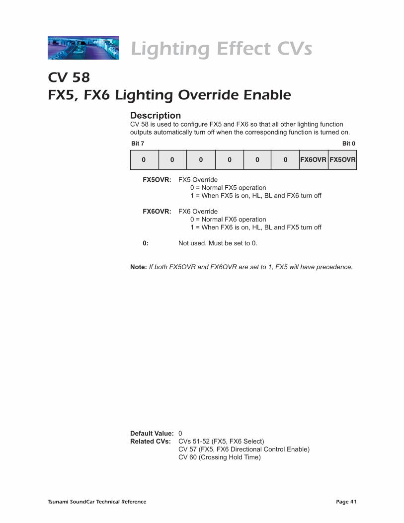
DescriptionCV 58 is used to configure FX5 and FX6 so that all other lighting function outputs automatically turn off when the corresponding function is turned on.
FX5OVR: FX5 Override 0 = Normal FX5 operation 1 = When FX5 is on, HL, BL and FX6 turn off
FX6OVR: FX6 Override 0 = Normal FX6 operation 1 = When FX6 is on, HL, BL and FX5 turn off
0: Not used. Must be set to 0.
Note: If both FX5OVR and FX6OVR are set to 1, FX5 will have precedence.
Default Value: 0Related CVs: CVs 51-52 (FX5, FX6 Select) CV 57 (FX5, FX6 Directional Control Enable) CV 60 (Crossing Hold Time)
Lighting Effect CVs
Bit 7 Bit 0
0 0 0 0 0 0 FX6OVR FX5OVR
Tsunami SoundCar Technical Reference Page 42
CV 59Flash Rate
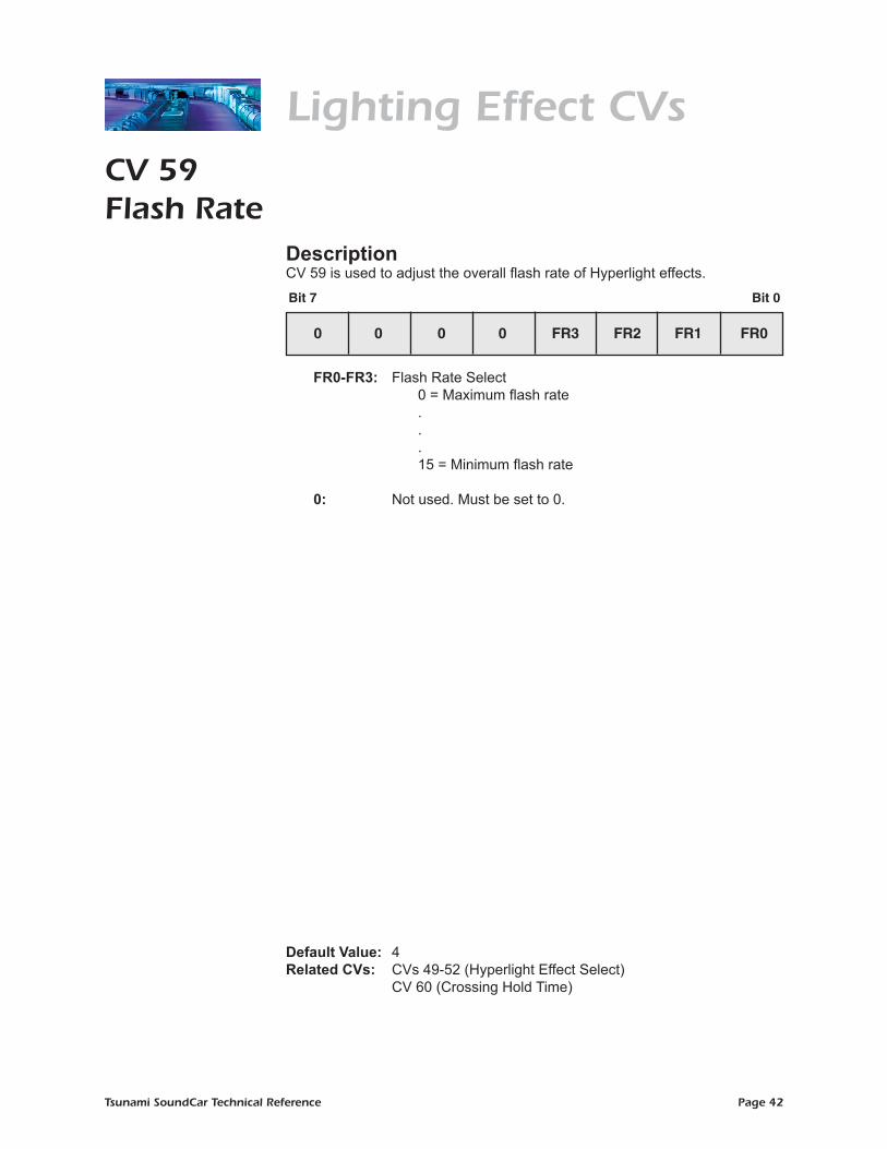
DescriptionCV 59 is used to adjust the overall flash rate of Hyperlight effects.
FR0-FR3: Flash Rate Select 0 = Maximum flash rate . . . 15 = Minimum flash rate
0: Not used. Must be set to 0.
Default Value: 4Related CVs: CVs 49-52 (Hyperlight Effect Select) CV 60 (Crossing Hold Time)
Lighting Effect CVs
Bit 7 Bit 0
0 0 0 0 FR3 FR2 FR1 FR0
Tsunami SoundCar Technical Reference Page 43
CV 60Crossing Hold Time
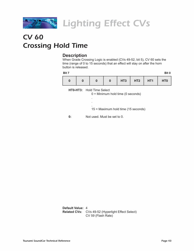
DescriptionWhen Grade Crossing Logic is enabled (CVs 49-52, bit 5), CV 60 sets the time (range of 0 to 15 seconds) that an effect will stay on after the horn button is released.
HT0-HT3: Hold Time Select 0 = Minimum hold time (0 seconds) . . . 15 = Maximum hold time (15 seconds)
0: Not used. Must be set to 0.
Default Value: 4Related CVs: CVs 49-52 (Hyperlight Effect Select) CV 59 (Flash Rate)
Bit 7 Bit 0
0 0 0 0 HT3 HT2 HT1 HT0
Lighting Effect CVs

Tsunami SoundCar Technical Reference Page 44
CV 61F11 Braking Rate
DescriptionThis CV contains a value from -127 to +127 that corresponds to the decoder’s baseline deceleration offset.
D0-D6: F11 Braking Rate
SIGN: Sign 0 = Positive value 1 = Negative value
Additional Information The F11 braking rate is added to or subtracted from the decoder’s base braking rate (CV 4) when the F11 button is pressed. Set this CV to the same value in your Tsunami-equipped locomotive to synchronize the F11 braking effect.
Note: A setting of +0 or -0 (CV 61 = 0 or 128) disables this feature.
Default Value: 0Related CV: CV 4 (Base Deceleration Rate)
Bit 7 Bit 0
SIGN D6 D5 D4 D3 D2 D1 D0
Misc. Control CVs

Tsunami SoundCar Technical Reference Page 45
CV 105User Identifier #1
DescriptionCV 105 provides storage for user-supplied data such as purchase date, serial numbers, spouse’s birthday, etc. Otherwise, this CV has no effect on decoder operation.
D0-D7: User Identifier Data
Additional Information This CV may be programmed with any value from 0 to 255.
When the decoder is reset to default values, CV 105 is reset to the software’s minor revision code.
Default Value: Varies by software revisionRelated CV: CV 106 (User Identifier #2)
User ID CVs
Bit 7 Bit 0
D7 D6 D5 D4 D3 D2 D1 D0

Tsunami SoundCar Technical Reference Page 46
CV 106User Identifier #2
DescriptionCV 106 provides storage for user-supplied data such as purchase date, serial numbers, spouse’s birthday, etc. Otherwise, this CV has no effect on decoder operation.
D0-D7: User Identifier Data
Additional Information This CV may be programmed with any value from 0 to 255.
When the decoder is reset to default values, CV 106 is reset to the software’s default CV value configuration.
Default Value: Varies by software revisionRelated CV: CV 105 (User Identifier #1)
User ID CVs
Bit 7 Bit 0
D7 D6 D5 D4 D3 D2 D1 D0
Tsunami SoundCar Technical Reference Page 47
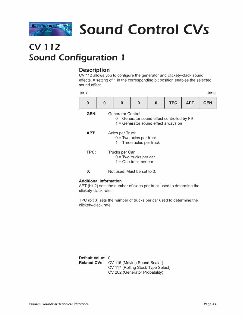
CV 112Sound Configuration 1
DescriptionCV 112 allows you to configure the generator and clickety-clack sound effects. A setting of 1 in the corresponding bit position enables the selected sound effect.
GEN: Generator Control 0 = Generator sound effect controlled by F9 1 = Generator sound effect always on APT: Axles per Truck
0 = Two axles per truck 1 = Three axles per truck
TPC: Trucks per Car 0 = Two trucks per car
1 = One truck per car
0: Not used. Must be set to 0.
Additional InformationAPT (bit 2) sets the number of axles per truck used to determine the clickety-clack rate. TPC (bit 3) sets the number of trucks per car used to determine the clickety-clack rate.
Default Value: 0Related CVs: CV 116 (Moving Sound Scalar) CV 117 (Rolling Stock Type Select) CV 202 (Generator Probability)
Sound Control CVs
Bit 7
Steam:
Bit 0
0 0 0 0 0 TPC APT GEN
Bit 7
Diesel:
Bit 0
RFE ACE

Tsunami SoundCar Technical Reference Page 48
CV 113Quiet Mode Time-out Period
DescriptionWhen CV 113 is set to a non-zero value, sound effects are only activated when the decoder is addressed. When the model is stopped and all functions have been turned off, sound effects will turn off automatically after the quiet mode time-out period has elapsed.
Q0-Q7: Quiet Mode Time-out Period 0 = Sound effects turn on a few seconds after power is turned on
1 = Minimum time-out period (0.25 seconds) .
. .
255 = Maximum time-out period (63.75 seconds) Additional Information The time-out period is calculated in seconds as:
Time-out Period (seconds) = CV 113 x 0.25
Default Value: 0
Sound Control CVs
Bit 7 Bit 0
Q7 Q6 Q5 Q4 Q3 Q2 Q1 Q0

Tsunami SoundCar Technical Reference Page 49
CV 114Bell Ring Rate
DescriptionCV 114 contains a value from 0 to 15 and is used to control the speed at which the bell rings.
BR0-BR3: Bell Ring Rate 0 = Fastest ring rate . . .
15 = Slowest ring rate
0: Not used. Must be set to 0.
Default Value: 4Related CVs: CV 130 (Bell Volume) CV 227 (Bell Select)
Note: Defauldt of 3 in previous software versions.
Sound Control CVs
Bit 7 Bit 0
0 0 0 0 BR3 BR2 BR1 BR0
Tsunami SoundCar Technical Reference Page 50
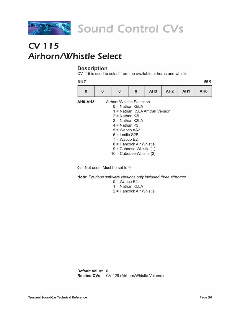
CV 115Airhorn/Whistle Select
DescriptionCV 115 is used to select from the available airhorns and whistle.
AH0-AH3: Airhorn/Whistle Selection 0 = Nathan K5LA 1 = Nathan K5LA Amtrak Version 2 = Nathan K3L 3 = Nathan K3LA 4 = Nathan P3 5 = Wabco AA2 6 = Leslie S2B 7 = Wabco E2 8 = Hancock Air Whistle 9 = Caboose Whistle (1) 10 = Caboose Whistle (2)
0: Not used. Must be set to 0.
Note: Previous software versions only included three airhorns: 0 = Wabco E2 1 = Nathan K5LA 2 = Hancock Air Whistle
Default Value: 0Related CVs: CV 129 (Airhorn/Whistle Volume)
Sound Control CVsSteam:
Bit 7
Diesel:
Bit 0
0 0 0 0 AH3 AH2 AH1 AH0
Bit 7 Bit 0
ALTWH AWH2 AWH1 AWH0 WH2 WH1 WH0
Tsunami SoundCar Technical Reference Page 51
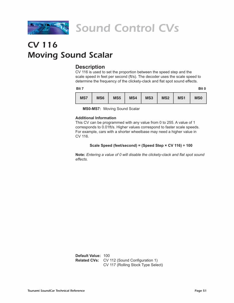
CV 116Moving Sound Scalar
DescriptionCV 116 is used to set the proportion between the speed step and the scale speed in feet per second (ft/s). The decoder uses the scale speed to determine the frequency of the clickety-clack and flat spot sound effects.
MS0-MS7: Moving Sound Scalar
Additional Information This CV can be programmed with any value from 0 to 255. A value of 1 corresponds to 0.01ft/s. Higher values correspond to faster scale speeds. For example, cars with a shorter wheelbase may need a higher value in CV 116.
Scale Speed (feet/second) = (Speed Step × CV 116) ÷ 100
Note: Entering a value of 0 will disable the clickety-clack and flat spot sound effects.
Default Value: 100
Related CVs: CV 112 (Sound Configuration 1) CV 117 (Rolling Stock Type Select)
Sound Control CVs
Bit 7 Bit 0
MS7 MS6 MS5 MS4 MS3 MS2 MS1 MS0

Tsunami SoundCar Technical Reference Page 52
CV 117Rolling Stock Type Select
DescriptionCV 117 can be programmed with a value from 0 to 255 to select sound effects appropriate to the type of car you are operating.
FE: Flat Spot Enable 0 = Flat spot sound effect off 1 = Flat spot sound effect on
GE: Generator Enable 0 = Generator sound effect off 1 = Generator sound effect on
CPE: Coupler Enable 0 = Coupler sound effects off 1 = Coupler sound effects on
HBE: Horn and Bell Enable 0 = Airhorns and bells off 1 = Airhorns and bells on
CCE: Clickety-Clack Enable 0 = Clickety-clack sound effect off 1 = Clickety-clack sound effect on
FSE: Flange Squeal Enable 0 = Flange squeal off 1 = Flange squeal on
WNE: Wheel Noise Enable 0 = Wheel noise off 1 = Wheel noise on
BSE: Brake Sounds Enable 0 = Brake sounds off 1 = Brake sounds on
Default Value: 254 Related CVs: CV 112 (Sound Configuration 1) CV 116 (Moving Sound Scalar) CV 128 (Master Volume Control) CVs 129-143 (Sound Mixer)
Sound Control CVs
Bit 7 Bit 0
BSE WNE FSE CCE HBE CPE GE FE

Tsunami SoundCar Technical Reference Page 53
CV 118Recovery Speed
DescriptionCV 118 adjusts the recovery speed for momentary interruptions in power during operation.
RS0-RS7: Recovery Speed 0 = Disabled
1-127 = Absolute limiting: When set from 1 to 127, the decoder will limit the recovery speed to the corresponding speed step.
128 = Disabled 129-255 = Proportional limiting: When set from 129 to 255,
the decoder will limit its power after a power loss to a specific percentage as calculated below:
Percentage = (CV 118 - 128) ÷ 127
Default Value: 204 (60%)
Misc. Control CVs
Bit 7 Bit 0
RS7 RS6 RS5 RS4 RS3 RS2 RS1 RS0

Tsunami SoundCar Technical Reference Page 54
CV 128Master Volume Control
DescriptionCV 128 sets the overall volume of all sound channels.
VOL 0-7: Master Volume Control 0 = Minimum volume . . . 255 = Maximum volume
Default Value: 192 (75%) Related CVs: CVs 129-143 (Sound Mixer)
Sound Control CVs
Bit 7 Bit 0
VOL7 VOL6 VOL5 VOL4 VOL3 VOL2 VOL1 VOL0

Tsunami SoundCar Technical Reference Page 55
CVs 129-144Sound Mixer
DescriptionCVs 129-144 set the volume of individual sound channels as follows:
MIX 0-7: Mixer Level 0 = Minimum sound level (0%) . . . 255 = Maximum sound level (100%)
CV Mixer Channel Sound Effect Default ValueCV 129 Mixer Channel 0 Airhorn/Whistle 225 CV 130 Mixer Channel 1 Bell 64 CV 131 Mixer Channel 2 Clickety-Clack 64 CV 132 Mixer Channel 3 Generator 25 CV 133 Mixer Channel 4 Flange Squeal 16 CV 134 Mixer Channel 5 Flat Spot 64 CV 135 Mixer Channel 6 Wheel Noise 32 CV 136 Mixer Channel 7 Uncoupling 64 CV 137 Mixer Channel 8 Coupler 64 CV 138 Mixer Channel 9 Brake Set 32 CV 139 Mixer Channel 10 Brake Squeal 64 CV 140 Mixer Channel 11 Retainer Valve 32 CV 141 Mixer Channel 12 Emergency Brake Valve 192 CV 142 Mixer Channel 13 Hand Brake Set 128 CV 143 Mixer Channel 14 Hand Brake Release 128
CV 144* Mixer Channel 15 Livestock 100
Note: Previous software versions do not support the BeastBanter feature.
Related CV: CV 128 (Master Volume Control)
Sound Control CVs
Bit 7 Bit 0
MIX7 MIX6 MIX5 MIX4 MIX3 MIX2 MIX1 MIX0
Tsunami SoundCar Technical Reference Page 56
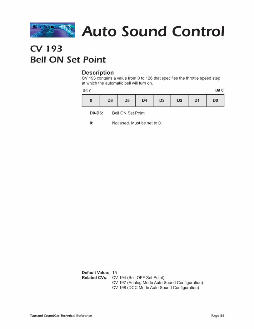
Auto Sound ControlCV 193Bell ON Set Point
DescriptionCV 193 contains a value from 0 to 126 that specifies the throttle speed step at which the automatic bell will turn on.
D0-D6: Bell ON Set Point 0: Not used. Must be set to 0.
Default Value: 15Related CVs: CV 194 (Bell OFF Set Point) CV 197 (Analog Mode Auto Sound Configuration) CV 198 (DCC Mode Auto Sound Configuration)
Bit 7 Bit 0
0 D6 D5 D4 D3 D2 D1 D0
Tsunami SoundCar Technical Reference Page 57
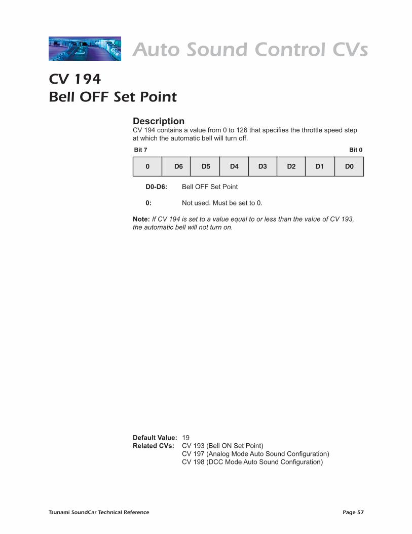
CV 194Bell OFF Set Point
DescriptionCV 194 contains a value from 0 to 126 that specifies the throttle speed step at which the automatic bell will turn off.
D0-D6: Bell OFF Set Point 0: Not used. Must be set to 0.
Note: If CV 194 is set to a value equal to or less than the value of CV 193, the automatic bell will not turn on.
Default Value: 19Related CVs: CV 193 (Bell ON Set Point) CV 197 (Analog Mode Auto Sound Configuration) CV 198 (DCC Mode Auto Sound Configuration)
Bit 7 Bit 0
0 D6 D5 D4 D3 D2 D1 D0
Auto Sound Control CVs

Tsunami SoundCar Technical Reference Page 58
Auto Sound Control CVsCV 195Grade Crossing Airhorn/Whistle Sensitivity
DescriptionCV 195 contains a value from 0 to 127 that specifies the positive rate of throttle change required to activate the automatic grade crossing airhorn/whistle.
D0-D6: Grade Crossing Airhorn/Whistle Sensitivity
0: Not used. Must be set to 0. Additional Information The CV setting is calculated as:
CV 195 Value = Speed Steps/Second ÷ 10
Default Value: 4Related CVs: CV 197 (Analog Mode Auto Sound Configuration) CV 198 (DCC Mode Auto Sound Configuration)
Bit 7 Bit 0
0 D6 D5 D4 D3 D2 D1 D0

Tsunami SoundCar Technical Reference Page 59
CV 197Analog Mode Automatic Sound Configuration
DescriptionCV 197 allows you to set parameters for automatic sound control features in analog mode.
AHXNG: Automatic Grade Crossing Enable 0 = Effect disabled
1 = Effect enabled
AHSIG: Automatic Horn Enable 0 = Effect disabled 1 = Effect enabled
BELL: Automatic Bell Enable 0 = Effect disabled 1 = Effect enabled
0: Not used. Must be set to 0.
Default Value: 6Related CVs: CVs 193-194 (Bell ON/OFF Set Point) CV 195 (Grade Crossing Airhorn/Whistle Sensitivity) CV 198 (DCC Mode Auto Sound Configuration)
Bit 7 Bit 0
0 0 0 0 0 BELL AHSIG AHXING
Auto Sound Control CVs

Tsunami SoundCar Technical Reference Page 60
CV 198DCC Mode Automatic Sound Configuration
DescriptionCV 198 allows you to set parameters for automatic sound control features in DCC mode.
AHXING: Automatic Grade Crossing Enable 0 = Effect disabled 1 = Effect enabled
AHSIG: Automatic Horn Enable 0 = Effect disabled 1 = Effect enabled
BELL: Automatic Bell Enable 0 = Effect disabled 1 = Effect enabled
0: Not used. Must be set to 0.
Default Value: 0 Related CVs: CVs 193-194 (Bell ON/OFF Set Point) CV 195 (Grade Crossing Airhorn/Whistle Sensitivity) CV 197 (Analog Mode Auto Sound Configuration)
Auto Sound Control CVs
Bit 7 Bit 0
0 0 0 0 0 BELL AHSIG AHXING
Tsunami SoundCar Technical Reference Page 61
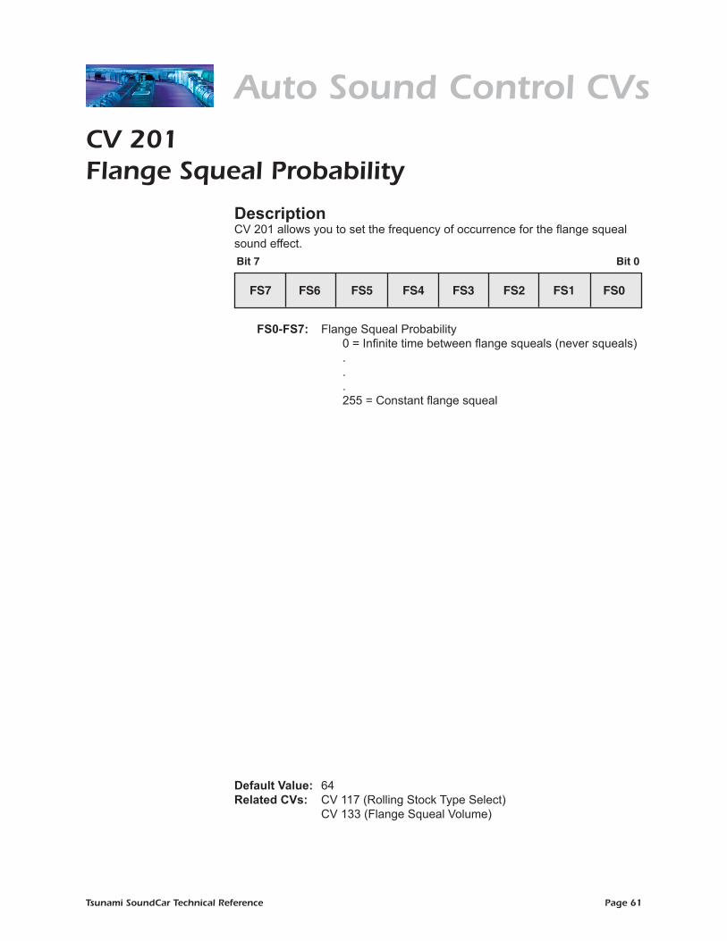
CV 201Flange Squeal Probability
DescriptionCV 201 allows you to set the frequency of occurrence for the flange squeal sound effect.
FS0-FS7: Flange Squeal Probability 0 = Infinite time between flange squeals (never squeals) . . . 255 = Constant flange squeal
Default Value: 64Related CVs: CV 117 (Rolling Stock Type Select) CV 133 (Flange Squeal Volume)
Auto Sound Control CVs
Bit 7 Bit 0
FS7 FS6 FS5 FS4 FS3 FS2 FS1 FS0
Tsunami SoundCar Technical Reference Page 62
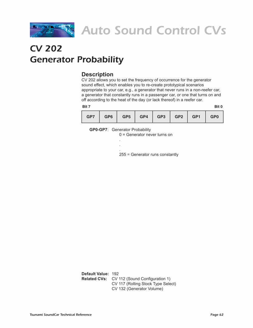
CV 202Generator Probability
DescriptionCV 202 allows you to set the frequency of occurrence for the generator sound effect, which enables you to re-create prototypical scenarios appropriate to your car, e.g., a generator that never runs in a non-reefer car, a generator that constantly runs in a passenger car, or one that turns on and off according to the heat of the day (or lack thereof) in a reefer car.
GP0-GP7: Generator Probability 0 = Generator never turns on . . . 255 = Generator runs constantly
Default Value: 192Related CVs: CV 112 (Sound Configuration 1) CV 117 (Rolling Stock Type Select) CV 132 (Generator Volume)
Auto Sound Control CVs
Bit 7 Bit 0
GP7 GP6 GP5 GP4 GP3 GP2 GP1 GP0
Tsunami SoundCar Technical Reference Page 63
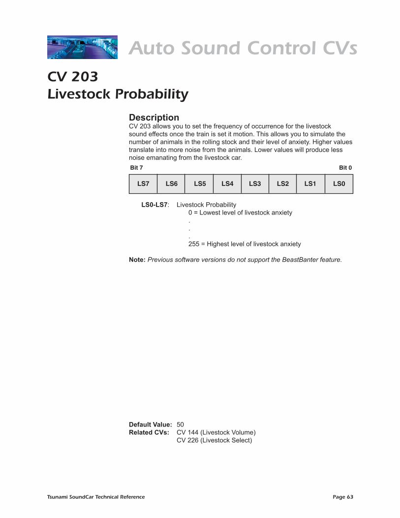
Auto Sound Control CVsCV 203Livestock Probability
DescriptionCV 203 allows you to set the frequency of occurrence for the livestock sound effects once the train is set it motion. This allows you to simulate the number of animals in the rolling stock and their level of anxiety. Higher values translate into more noise from the animals. Lower values will produce less noise emanating from the livestock car.
LS0-LS7: Livestock Probability 0 = Lowest level of livestock anxiety
. . . 255 = Highest level of livestock anxiety
Note: Previous software versions do not support the BeastBanter feature.
Default Value: 50Related CVs: CV 144 (Livestock Volume) CV 226 (Livestock Select)
Bit 7 Bit 0
LS7 LS6 LS5 LS4 LS3 LS2 LS1 LS0

Tsunami SoundCar Technical Reference Page 64
Auto Sound Control CVsCV 226Livestock Select
DescriptionCV 226 is used to select the type of animal replicated by the BeastBanter effect. A value of 0 will disable the livestock feature.
LS0-LS1: Livestock Select 0 = Disabled 1 = Cattle 2 = Sheep
0: Not used. Must be set to 0.
Note: Previous software versions do not support the BeastBanter feature.
Default Value: 0Related CVs: CV 144 (Livestock Volume) CV 203 (Livestock Probability)
Bit 7 Bit 0
0 0 0 0 0 0 LS1 LS0

Tsunami SoundCar Technical Reference Page 65
Sound Control CVs
Bit 7 Bit 0
0 0 0 0 0 BS2 BS1 BS0
CV 227Bell Select
DescriptionCV 227 is used to select the bell sound effect.
BS0-BS1: Bell Select 0 = Modern Cast 1 = Bronze Cast 2 = Cast 3 = Electronic bell 4 = Gong bell
0: Not used. Must be set to 0. Note: Previous software releases only contian three bell sound effects: 0 = Cast 1 = Electronic bell 2 = Gong bell
Default Value: 0Related CVs: CV 114 (Bell Ring Rate) CV 130 (Bell Volume)
Tsunami SoundCar Technical Reference Page 66
Misc. Control CVs
Bit 7 Bit 0
0 0 0 0 FOL3 FOL2 FOL1 FOL0
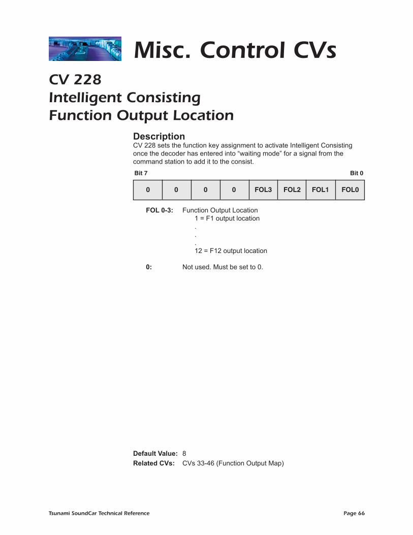
CV 228Intelligent Consisting Function Output Location
DescriptionCV 228 sets the function key assignment to activate Intelligent Consisting once the decoder has entered into “waiting mode” for a signal from the command station to add it to the consist.
FOL 0-3: Function Output Location 1 = F1 output location . . . 12 = F12 output location
0: Not used. Must be set to 0.
Default Value: 8Related CVs: CVs 33-46 (Function Output Map)

Tsunami SoundCar Technical Reference Page 67
©2017 Throttle Up! Corp.All Rights Reserved.
COMPATIBLE WITHTHE NMRA DCC STANDARDS AND RECOMMENDED PRACTICES
DCC
®
New Dimensions in Digital Sound Technology
141 Burnett Drive, Durango CO 81301, U.S.A.(970) 259-0690 • Toll Free: (888) 789-7637 • Fax: (970) 259-0691
www.soundtraxx.com • [email protected]