distillation basic training
TRANSCRIPT
What is Distillation
• The distillation system is used to separate the alcohol from fermented mash.
Distillation System
• The distillation system starts at the beer well.
• The beer well is where the finished fermenters get sent to be processed by the distillation system.
• The beer well is composed of an alcohol percentage of 16-19%, 11-13% solids (yeast and grain solids), and the remaining is 69-73% water.
• From here it goes to the beer tank.

Beer Pre-Heating
• The beer from the beer well, which is ~90º F is pumped first to the Beer/Mash exchanger where it is heated by the ~185ºF liquefaction product liquid.
• From the Beer/Mash heat exchanger the beer which is now 115°F goes to the beer tank.
• The pre-heated beer then goes to the 1501 heat exchanger where it is further heated by Sieve vapor.
Beer Pre-Heating
• The beer then goes to one of the 1505 heat exchangers where it is further heated by beer column bottoms product (whole stillage).
• Beer bottoms is around 228 degrees F entering this exchanger and ~190º on exit.
• The heated beer then enters into the degasser.


Beer Pre-heat exchangers
• The Beer/Mash and 1505a and 1505b are alfa lavel plate and frame exchangers.
• The 1501 is a Tube and Shell type heat exchanger.
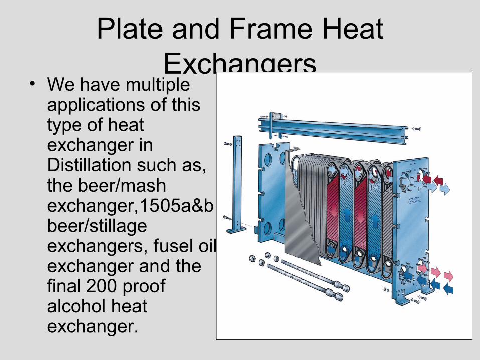
Plate and Frame Heat Exchangers
• We have multiple applications of this type of heat exchanger in Distillation such as, the beer/mash exchanger,1505a&b beer/stillage exchangers, fusel oil exchanger and the final 200 proof alcohol heat exchanger.
The Degasser
• Beer from the 1505a&b beer/stillage heat exchangers enters the degasser vessel.
• The purpose of the degasser is to purge off a portion of the carbon dioxide (CO2) contained in the beer.
The Degasser
• CO2 is formed from the yeast metabolism in fermentation and 5-10% of the CO2 produced will be entrained (trapped) in the liquid.
The Degasser• The heat from the previous heat exchange
causes the CO2 to expand and the degasser mixing and vacuum vent will allow most of the entrained gas to escape.
• Poor degassing of the beer can result in excess pressure in the distillation columns and can also result in higher acidity in the final product alcohol.
The Degasser
• CO2 in water at high temperature forms Carbonic acid.
• From the degasser the beer feed goes to the beer column.
The Binary Column
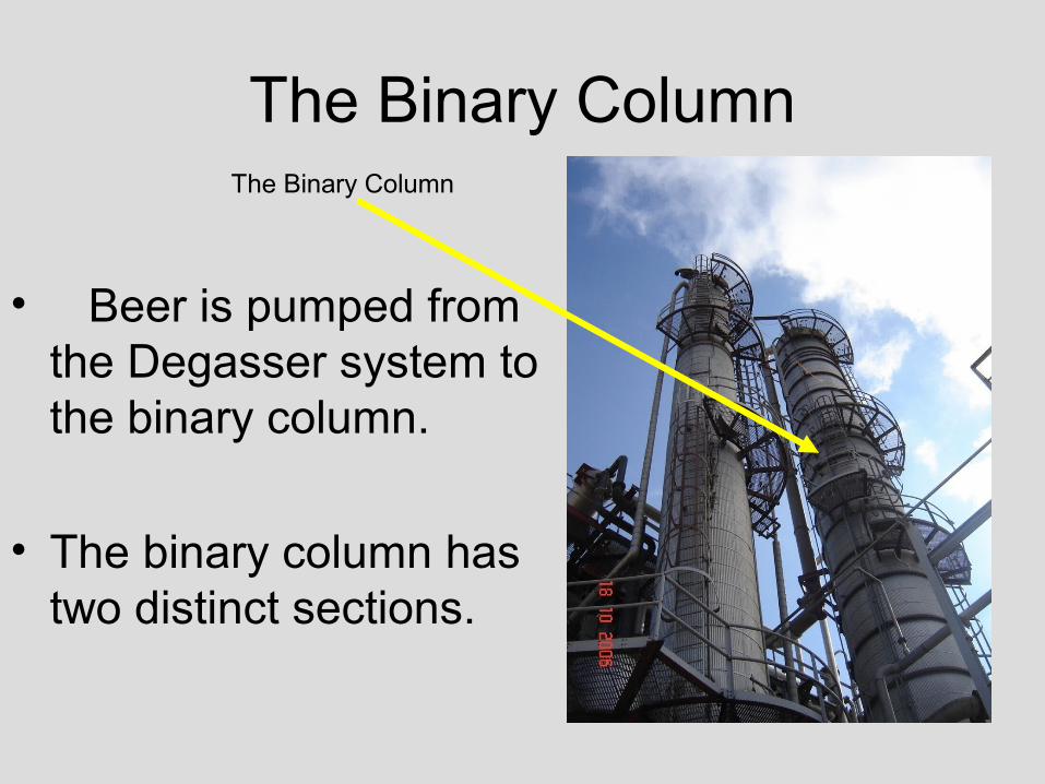
• Beer is pumped from the Degasser system to the binary column.
• The binary column has two distinct sections.
The Binary Column
The Binary Column
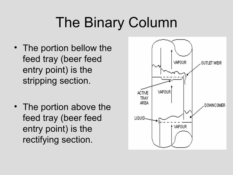
• The portion bellow the feed tray (beer feed entry point) is the stripping section.
• The portion above the feed tray (beer feed entry point) is the rectifying section.
The Binary Column• The stripping (bottom)
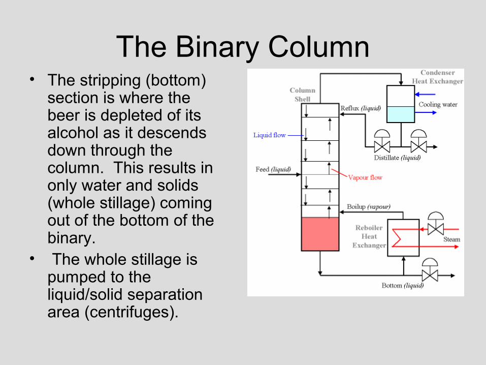
section is where the beer is depleted of its alcohol as it descends down through the column. This results in only water and solids (whole stillage) coming out of the bottom of the binary.
• The whole stillage is pumped to the liquid/solid separation area (centrifuges).

The Binary Column• The low proof alcohol travels up through the
column.
• Increasing in proof as it ascends up the column.
• The rectifying (top) section further separates the alcohol and water (Alcohol which has a lower boiling point than water and vaporizes first rising up through the trays in the column where it comes in contact with the falling liquid and concentrates to 190 proof at the top of the column.

The Binary Column Continued
• This vapor is condensed with tube and shell heat exchangers and is collected in the binary 190 overhead tank. Approximately 65% of this liquid is sent back into the binary for reflux. The remaining 35% is sent to the 190 surge tank to wait for further processing.
• The reflux is used to maintain the amount of alcohol necessary inside the binary column, which improves the separating of the alcohol and water and the concentrating of the alcohol to 190 proof.
Binary Column Operating Information
• The operating temperatures of the Binary are 228° F at the bottom and 170°F to 180°F at the top.
• Temperatures are measured at specific points between the top and bottom as well which give a thermal description of the Binary performance.
The Binary Column Re-boilers
• The heat source for the binary column is indirect steam from the boiler, utilizing two tube and shell type heat exchangers, the 1511A and 1511B. Steam on the shell side and binary bottoms on the tube side which are forced re-circulated with the 1511A and 1511B pumps.

The Binary Column Re-boilers
• Mash is pulled out of the bottom of the column and pumped through the tubes of the horizontal tube & shell re-boilers.
• Steam is introduced to the shell side and transfers energy into the column bottoms.

The Binary Column Re-boilers
• Backpressure is kept on the liquid bottoms stream until part of it "flashes" (turns to steam) back into the base of the column.
• This ensures the tubes of the exchanger stay full of liquid at all times.

The Binary Column Re-boilers
• These re-boilers introduce the majority of energy into the column.
• During re-boiler cleanings and re-circulation pump maintance the column can also be supplied with directly injected steam

Binary 190 Proof Condensers
• All of the vapor off the top of the column is pulled into Binary 190 proof overhead condensers.
• The condensers are installed in a series arraignment, vapor on the shell side and liquid on the tube side.

Binary 190 Proof Condensers
• The liquid that is on the tube side is cooling tower water.
• The condensed 190 proof liquid goes to the Binary 190 tank.

Binary 190 Proof Tank
• This tank collects the 190 proof condensate from the overhead Binary condensers.
• The strength is 190 proof alcohol.
• Approximately 66% of this liquid is sent back to the binary for reflux.
• The remaining 34% is sent to the 190 proof surge tank waiting further processing.

Tube and Shell Heat Exchangers
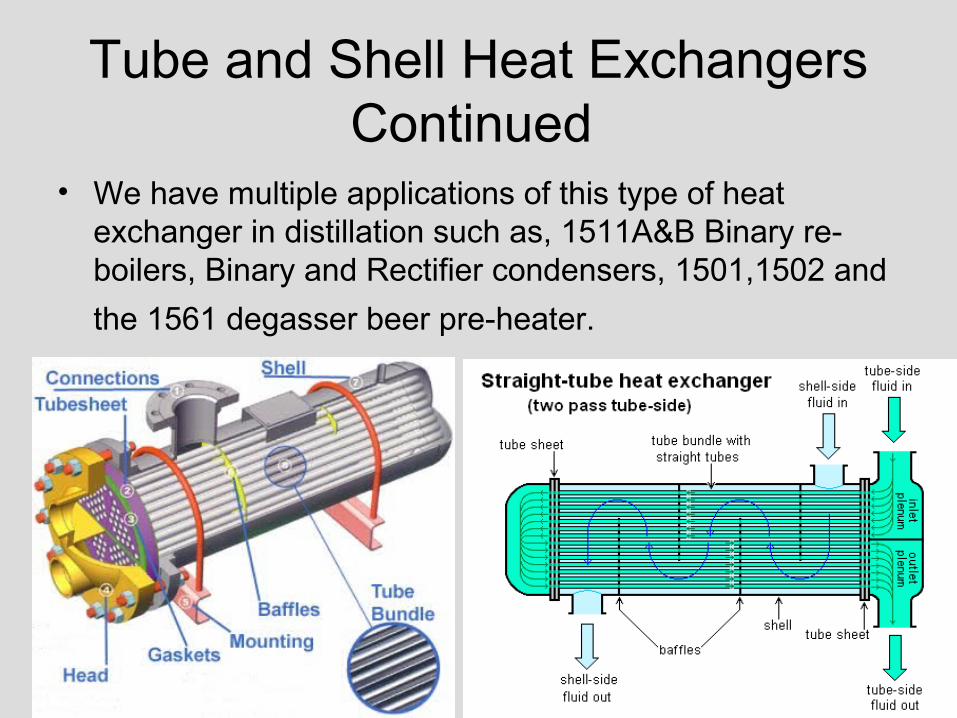
Tube and Shell Heat ExchangersContinued
• We have multiple applications of this type of heat exchanger in distillation such as, 1511A&B Binary re-boilers, Binary and Rectifier condensers, 1501,1502 and
the 1561 degasser beer pre-heater.
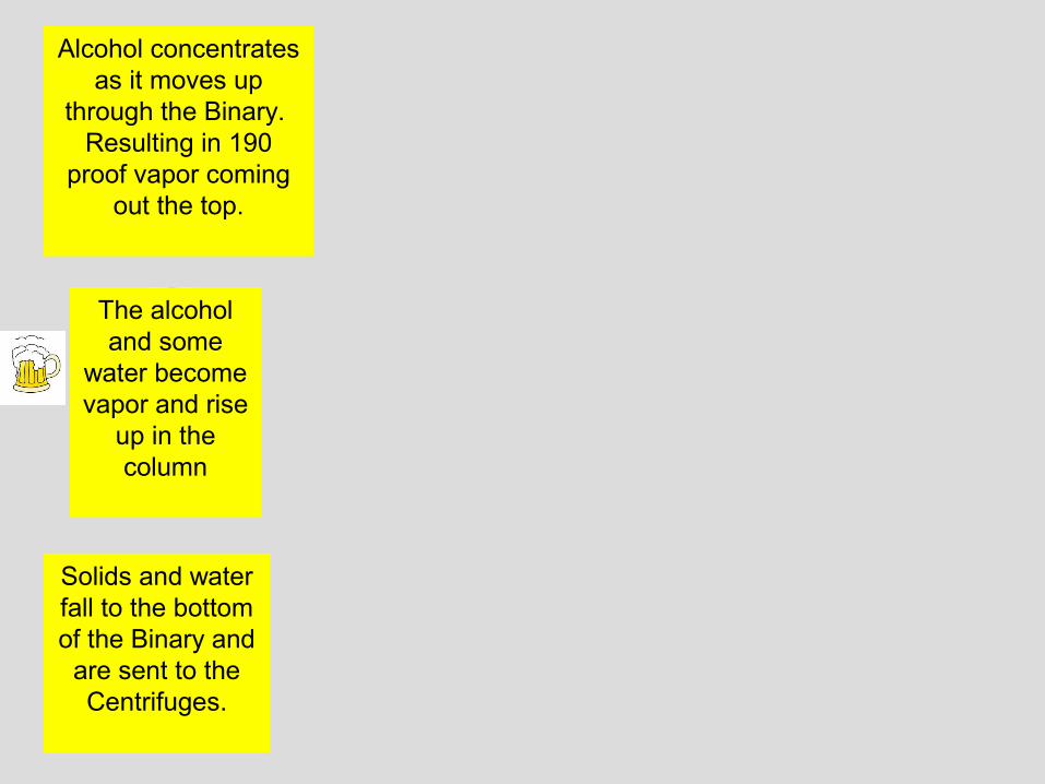
Alcohol concentrates as it moves up
through the Binary. Resulting in 190
proof vapor coming out the top.
The alcohol and some
water become vapor and rise
up in the column
Solids and water fall to the bottom of the Binary and
are sent to the Centrifuges.

Rectifier Column
• The purpose of the Rectifier column is to separate water and alcohol.
• The rectifier takes secondary water streams (liquid from the distillation vacuum system, sieve regeneration system, binary chimney tray, fusel washer, sieve vaporizer purge and Co2 scrubbers) and separates the alcohol and water.
Rectifier Column
• Alcohol which has a lower boiling point than water and vaporizes first rising up through the trays in the column where it comes in contact with the falling liquid and concentrates to 190 proof at the top of the column.
• This vapor is condensed with a tube and shell heat exchanger and is collected in the rectifier 190 overhead tank. Approximately 65% of this liquid is sent back to the rectifier for reflux. The remaining 35% is sent to the 190 surge tank to wait for further processing.
How the Rectifier Column works
• The reflux is used to maintain the amount of alcohol necessary inside the rectifier column, which improves the separating of the alcohol and water and the concentrating of the alcohol to 190 proof.
• The water which has been depleted of all alcohol collects in the bottom of the rectifier and is pumped to the recycle water tank.
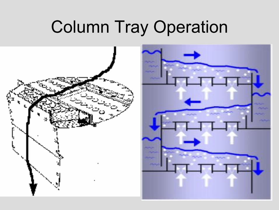
Column Tray Operation
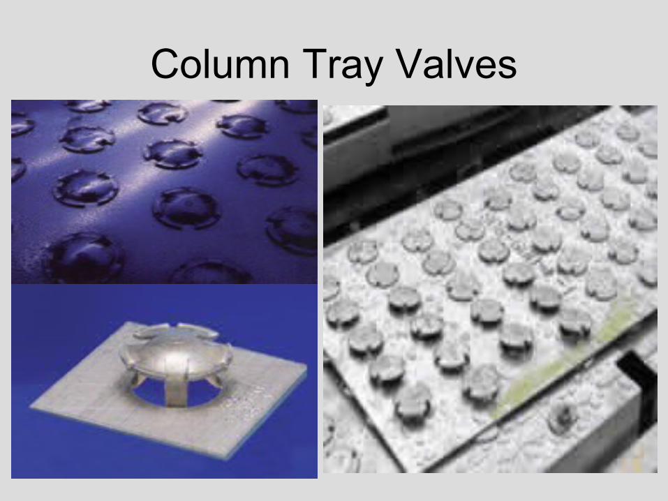
Column Tray Valves
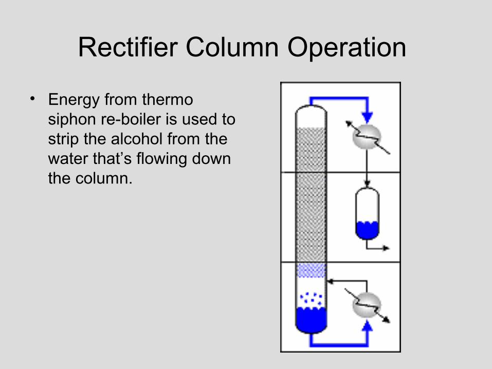
Rectifier Column Operation
• Energy from thermo siphon re-boiler is used to strip the alcohol from the water that’s flowing down the column.
Thermo Siphon Re-boiler
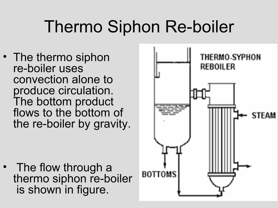
• The thermo siphon re-boiler uses convection alone to produce circulation. The bottom product flows to the bottom of the re-boiler by gravity.
• The flow through a thermo siphon re-boiler is shown in figure.
Thermo Siphon Re-boiler
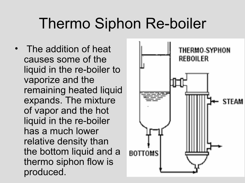
• The addition of heat causes some of the liquid in the re-boiler to vaporize and the remaining heated liquid expands. The mixture of vapor and the hot liquid in the re-boiler has a much lower relative density than the bottom liquid and a thermo siphon flow is produced.

Rectifier 190 Proof Condenser
• All of the vapor off the top of the column is pulled into Rectifier 190 proof overhead condenser.
• The condenser is a typical tube and shell arraignment, vapor on the shell side and liquid on the tube side.
Rectifier 190 Proof Condenser
• The liquid that is on the shell side is cooling tower water.
• The condensed 190 proof liquid goes to the Rectifier 190 tank.
Rectifier 190 Tank
• This tank collects the condensate from the overhead rectifier column vapor.
• The strength is 190 proof alcohol.
• Approximately 66% of this liquid is sent back to the rectifier for reflux.
• The remaining 34% is sent to the 190 proof surge tank waiting further processing.

Fusel Oil• Fusel oils are high molecular weight alcohols formed
as byproducts in fermentation.
• The higher molecular weight alcohol, or fusel oils, have a property of being more volatile than alcohol in dilute aqueous solution, but are less volatile than alcohol in concentrated alcohol solution.
• Therefore, they tend to concentrate on trays in the middle of the rectifying section of a column.

Fusel Oil
• If this oil builds up on the trays a fusel oil block forms preventing vapor from moving up the column.
• These fusel oils are removed from the column as a liquid, side draw stream from any one of the different draw ports.
• The liquid from the fusel oil draws are fed to the fusel decanter (washer).

Fusel Oil
• The light fusel oil stream is decanted from the fusel oil washer and sent to the fusel oil tank.
• The fusel oil is blended into the 200 proof final produce as applicable.