vrvii basic training
TRANSCRIPT

SiE30-408
Service
Manual
Basic Training Manual
The latest technological innovations of air conditioners make remarkable progress. We are not able to perform our duty without mastering the proper basic theory and knowledge in service skills and techniques.The field of VRV system particularly shows such a rising tendency. The techniques on trouble shooting and trouble removing corresponding to the computerized and systematized products are required. Based on these requests, therefore, we have prepared this manual, emphasizing the understanding on VRV system.We wish that you would use this manual as a guidebook for the service of VRV system or as a reference book for education of service personnel, which leads to the development of skills in whole service group of Daikin.
DEC.2004
DAIKIN INDUSTRIES, LTD.After Sales Service Division
SiE30-408
General Contents i

SiE30-408
ii General Contents

SiE30-408
Introduction 1
1. What is a VRV System?..........................................................................22. List of VRV Unit Models ..........................................................................3
2.1 List of Outdoor Unit Models......................................................................32.2 Nomenclature ...........................................................................................5
3. System Basic Configuration ..................................................................113.1 Cooling / Heating Selection -Standard- System .....................................113.2 Heat Recovery (Cooling / Heating Individual Operating) System...........14
4. Super Wiring System ............................................................................154.1 Points of Super Wiring System...............................................................154.2 Wiring Length .........................................................................................16
5. REFNET Piping.....................................................................................175.1 Allowable Length of Refrigerant Piping ..................................................175.2 For Refrigerant Piping ............................................................................19
What is a VRV System? SiE30-408
2 Introduction
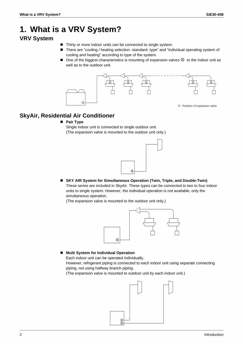
1. What is a VRV System?VRV System
Thirty or more indoor units can be connected to single system.There are "cooling / heating selection -standard- type" and "individual operating system of cooling and heating" according to type of the system.One of the biggest characteristics is mounting of expansion valves ⊗ to the indoor unit as well as to the outdoor unit.
SkyAir, Residential Air ConditionerPair TypeSingle indoor unit is connected to single outdoor unit.(The expansion valve is mounted to the outdoor unit only.)
SKY AIR System for Simultaneous Operation (Twin, Triple, and Double-Twin)These series are included in SkyAir. These types can be connected to two to four indoor units to single system. However, the individual operation is not available, only the simultaneous operation.(The expansion valve is mounted to the outdoor unit only.)
Multi System for Individual OperationEach indoor unit can be operated individually.However, refrigerant piping is connected to each indoor unit using separate connecting piping, not using halfway branch piping.(The expansion valve is mounted to outdoor unit by each indoor unit.)
: Position of expansion valve

SiE30-408 List of VRV Unit Models
Introduction 3
2. List of VRV Unit Models2.1 List of Outdoor Unit Models
Type R22 C to H series R22 K series
Sta
ndar
ad C
omp.
Typ
e
VRV Standard C series VRV for High outdoor temp (with unloader comp.)
Model Type Service manual Model Type Service manual
—RSC10,15C
—Cooling only
—(ES20-2)
RSNY8KTAL Heat-pump Si-06
VRV Standard D series
Model Type Service manual
RSCY10,15D—
Heat-pump—
Si-46A—
VRV Standard G series
Model Type Service manual
RSCY5,10GRSC5,10G
Heat-pumpCooling only
Si-45FSi-45F
VRV Standard F series
Model Type Service manual
RSCY10,15FRSC10,15F
Heat-pumpCooling only
Si-46ASi-46A
Sm
all C
apac
ity In
vert
er T
ype
VRV Inverter G series VRV Inverter K series
Model Type Service manual Model Type Service manual
RSXY5-10G(J)RSX8,10G(J)RSEY8,10G(J)
Heat-pumpCooling onlyHeat recovery
Si-45FSi-45FSi-45F
RSXY5-10KRSX5-10KRSEY8,10K
Heat-pumpCooling onlyHeat recovery
Si-05CSi-05C
—
VRV Inverter H series VRV Inverter KU series
Model Type Service manual Model Type Service manual
RSXY5-10H(J)RSX5-10H(J)
Heat-pumpCooling only
Si-46CSi-46C
RSX5-10KU Cooling only Si-91
VRV Inverter KA series
Model Type Service manual
RSX5-10KA Cooling only Si-92
VRV Inverter K series (H/R with Scroll Comp.)
Model Type Service manual
RSEY8-10KLY1 Heat recovery Si-95
High
CO
P In
verte
r Typ
eLa
rge
Cap
acity
Inve
rter
Typ
e
VRV Plus series
Model Function unit Inverter Cnstant Speed Type Service manual
RXY16-30KRX16-30KREY16-30K
BL2 or 3KBC2 or 3KBR2 or 3K
RXY8 or 10KRX8 or 10KRXY8 or 10K
RNY8 or 10KRN8 or 10KRNY8 or 10K
Heat-pumpCooling onlyHeat recovery
Si-05CSi-05CSi-11
VRV Plus series for High outdoor temp
Model Function unit Inverter Cnstant Speed Condenser Type Service manual
RXY16-30K-KRX16-30K-K
BL2 or 3KBC2 or 3K
RXY8 or 10KRX8 or 10K
RNY8 or 10KRN8 or 10K
RXE2 or 3KRXE2 or 3K
Heat-pumpCooling only
Si-94Si-94
VRV R22 Plus series
Model Main unit Sub unit Type Service manual
RSXY16-30KA RXY8 or 10KA RXE8 or 10KA Heat-pump Si33-101
VRV II series
Model Module Type Service manual
RXY5-48MRX5-48M
RXY8-16MRX8-16M
Heat-pumpCooling only
Si38-304Si38-304
List of VRV Unit Models SiE30-408
4 Introduction
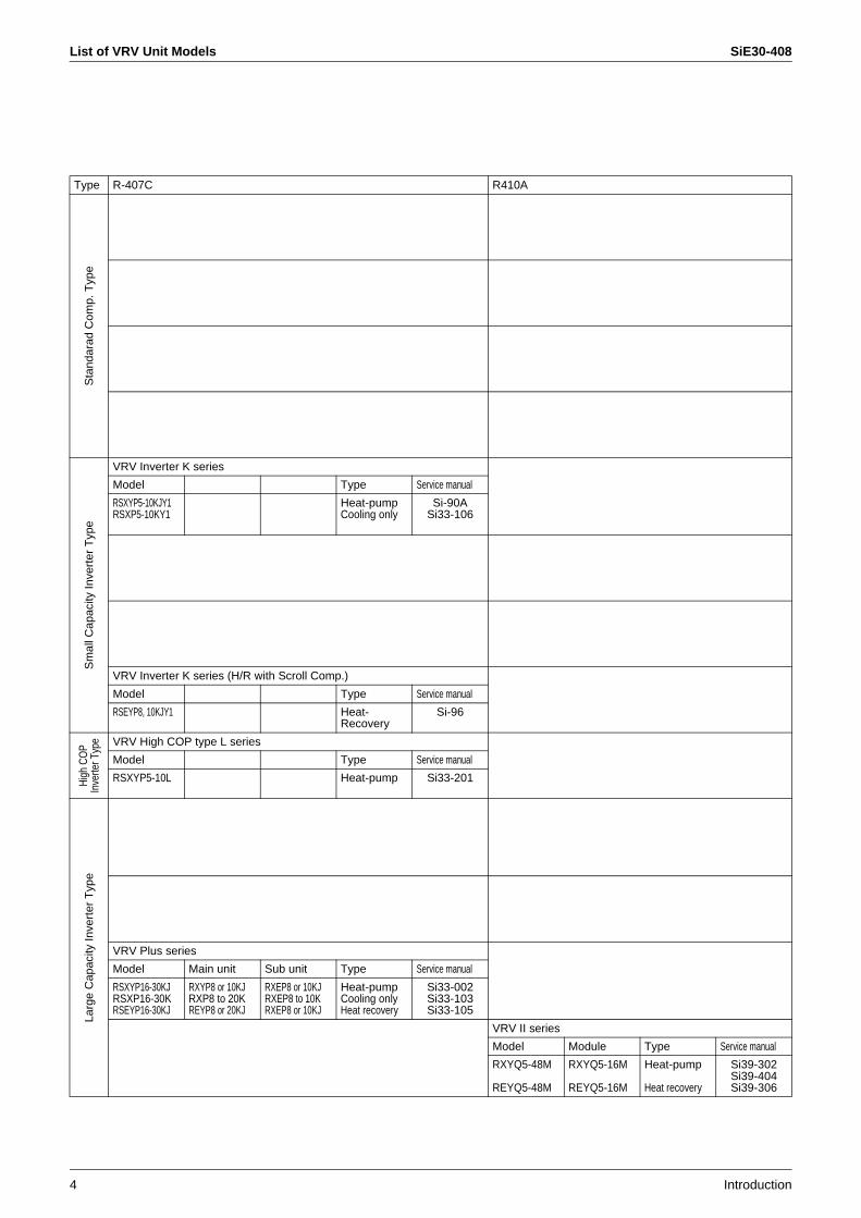
Type R-407C R410A
Sta
ndar
ad C
omp.
Typ
eS
mal
l Cap
acity
Inve
rter
Typ
e
VRV Inverter K series
Model Type Service manual
RSXYP5-10KJY1RSXP5-10KY1
Heat-pumpCooling only
Si-90ASi33-106
VRV Inverter K series (H/R with Scroll Comp.)
Model Type Service manual
RSEYP8, 10KJY1 Heat-Recovery
Si-96
Hig
h C
OP
Inve
rter T
ype VRV High COP type L series
Model Type Service manual
RSXYP5-10L Heat-pump Si33-201
Larg
e C
apac
ity In
vert
er T
ype
VRV Plus series
Model Main unit Sub unit Type Service manual
RSXYP16-30KJRSXP16-30KRSEYP16-30KJ
RXYP8 or 10KJRXP8 to 20KREYP8 or 20KJ
RXEP8 or 10KJRXEP8 to 10KRXEP8 or 10KJ
Heat-pumpCooling onlyHeat recovery
Si33-002Si33-103Si33-105
VRV II series
Model Module Type Service manual
RXYQ5-48M
REYQ5-48M
RXYQ5-16M
REYQ5-16M
Heat-pump
Heat recovery
Si39-302Si39-404Si39-306

SiE30-408 List of VRV Unit Models
Introduction 5
2.2 Nomenclature2.2.1 Nomenclature (Previous indication)
Indoor Unit
Power supply symbolV1 : Single phase 220 to 240V, 50HzVE : Single phase 220 to 240V, 50Hz : 220V, 60HzVAL : Single phase 220V, 60Hz
Indicates major design categoryKA : Models for ceiling mounted low silhouette duct type Models for ceiling suspended typeKB : Models for super cassetteKJ : Models applied for EC regulationKF : Outdoor air processing unit
Capacity IndicationConversion to horsepower:20 : 0.8 HP 50 : 2.0 HP 125 : 5 HP25 : 1 HP 63 : 2.5 HP 200 : 8 HP32 : 1.25 HP 80 : 3.2 HP 250 : 10 HP 40 : 1.6 HP 100 : 4 HP
Refrigerant typeNo indication : R22P : R407C
Type of unitC : Ceiling mounted cassette type (Double flow)F : Ceiling mounted cassette type (Multi flow) – Super cassette –K : Ceiling mounted cassette corner typeD : Ceiling mounted low silhouette duct type (Low static pressure)S : Ceiling mounted built-in typeB : Ceiling mounted built-in (Rear suction)M : Ceiling mounted duct type or outdoor air processing unitH : Ceiling suspended typeA : Wall mounted typeL : Floor standing typeLM : Concealed floor standing typeN : Concealed floor standing type
Indicates that this is a INVERTER SERIES indoor unit.FX : Cooling OnlyFXY : Heat Pump
C 40 V1KPFXY
(V1217)

List of VRV Unit Models SiE30-408
6 Introduction
Indoor Unit
Power supply symbolV1 : Single phase 220 to 240V, 50Hz
Indicates major design categoryB: New ceiling suspended cassetteK: Wall mounted type 40-63
Capacity IndicationConversion to horsepower:40 : 1.6HP 50 : 2.0HP 63 : 2.5HP71 : 3 HP 100 : 4 HP 125 : 5 HP
Refrigerant : R407C
Type of unitFUY : New ceiling suspended cassette typeFXYA : Wall mounted type 40-63
P 71 V1BFUY
(V2863)
SiE30-408 List of VRV Unit Models
Introduction 7
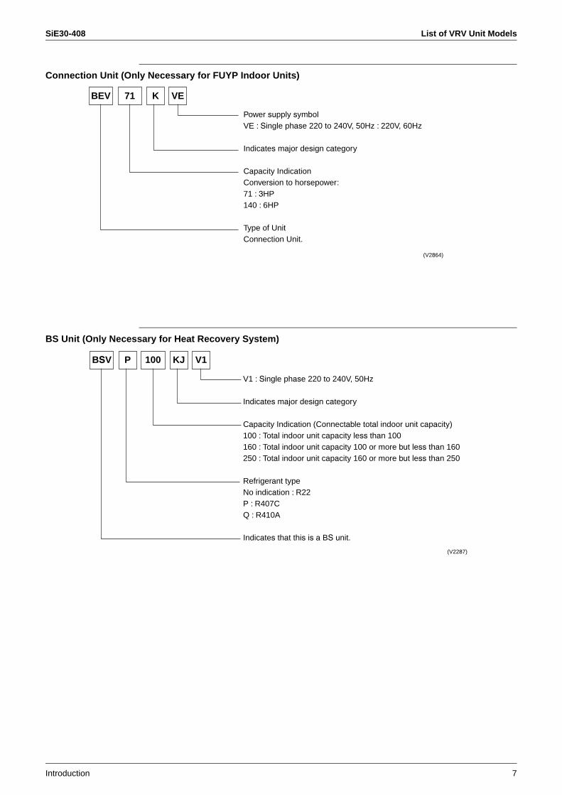
Connection Unit (Only Necessary for FUYP Indoor Units)
BS Unit (Only Necessary for Heat Recovery System)
Power supply symbolVE : Single phase 220 to 240V, 50Hz : 220V, 60Hz
Indicates major design category
Capacity IndicationConversion to horsepower: 71 : 3HP140 : 6HP
Type of UnitConnection Unit.
BEV K VE71
(V2864)
V1 : Single phase 220 to 240V, 50Hz
Indicates major design category
Capacity Indication (Connectable total indoor unit capacity)100 : Total indoor unit capacity less than 100160 : Total indoor unit capacity 100 or more but less than 160250 : Total indoor unit capacity 160 or more but less than 250
Refrigerant typeNo indication : R22P : R407CQ : R410A
Indicates that this is a BS unit.
BSV KJ V1P 100
(V2287)
List of VRV Unit Models SiE30-408
8 Introduction
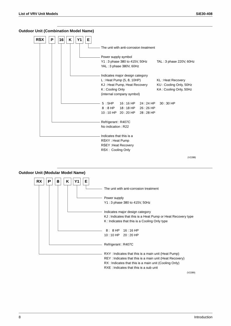
Outdoor Unit (Combination Model Name)
Outdoor Unit (Modular Model Name)
Y1K
The unit with anti-corrosion treatment
Power supply symbolY1 : 3 phase 380 to 415V, 50Hz TAL : 3 phase 220V, 60HzYAL : 3 phase 380V, 60Hz
Indicates major design categoryL : Heat Pump (5, 8, 10HP) KL : Heat RecoveryKJ : Heat Pump, Heat Recovery KU : Cooling Only, 50HzK : Cooling Only KA : Cooling Only, 50Hz(internal company symbol)
5 : 5HP 16 : 16 HP 24 : 24 HP 30 : 30 HP8 : 8 HP 18 : 18 HP 26 : 26 HP10 : 10 HP 20 : 20 HP 28 : 28 HP
Refrigerant : R407CNo indication : R22
Indicates that this is aRSXY : Heat PumpRSEY :Heat RecoveryRSX : Cooling Only
16 EPRSX
(V2288)
The unit with anti-corrosion treatment
Power supplyY1 : 3 phase 380 to 415V, 50Hz
Indicates major design categoryKJ : Indicates that this is a Heat Pump or Heat Recovery typeK : Indicates that this is a Cooling Only type
8 : 8 HP 16 : 16 HP10 : 10 HP 20 : 20 HP
Refrigerant : R407C
RXY : Indicates that this is a main unit (Heat Pump)REY : Indicates that this is a main unit (Heat Recovery)RX : Indicates that this is a main unit (Cooling Only)RXE : Indicates that this is a sub unit
EY18 KRX P
(V2289)
SiE30-408 List of VRV Unit Models
Introduction 9
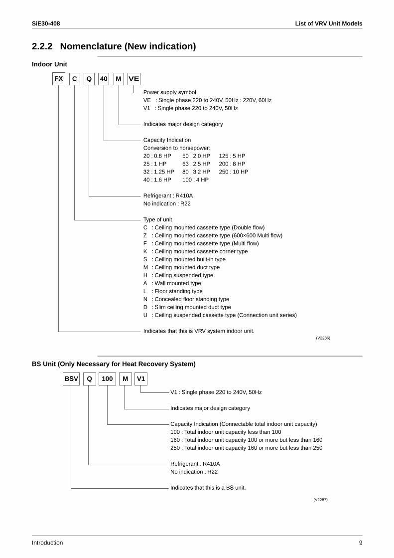
2.2.2 Nomenclature (New indication)
Indoor Unit
BS Unit (Only Necessary for Heat Recovery System)
Power supply symbolVE : Single phase 220 to 240V, 50Hz : 220V, 60HzV1 : Single phase 220 to 240V, 50Hz
Indicates major design category
Capacity IndicationConversion to horsepower:20 : 0.8 HP 50 : 2.0 HP 125 : 5 HP25 : 1 HP 63 : 2.5 HP 200 : 8 HP32 : 1.25 HP 80 : 3.2 HP 250 : 10 HP 40 : 1.6 HP 100 : 4 HP
Refrigerant : R410ANo indication : R22
Type of unitC : Ceiling mounted cassette type (Double flow)Z : Ceiling mounted cassette type (600×600 Multi flow)F : Ceiling mounted cassette type (Multi flow) K : Ceiling mounted cassette corner typeS : Ceiling mounted built-in typeM : Ceiling mounted duct typeH : Ceiling suspended typeA : Wall mounted typeL : Floor standing typeN : Concealed floor standing typeD : Slim ceiling mounted duct typeU : Ceiling suspended cassette type (Connection unit series)
Indicates that this is VRV system indoor unit.
C 40 VEMQFX
(V2286)
V1 : Single phase 220 to 240V, 50Hz
Indicates major design category
Capacity Indication (Connectable total indoor unit capacity)100 : Total indoor unit capacity less than 100160 : Total indoor unit capacity 100 or more but less than 160250 : Total indoor unit capacity 160 or more but less than 250
Refrigerant : R410ANo indication : R22
Indicates that this is a BS unit.
BSV M V1Q 100
(V2287)
List of VRV Unit Models SiE30-408
10 Introduction
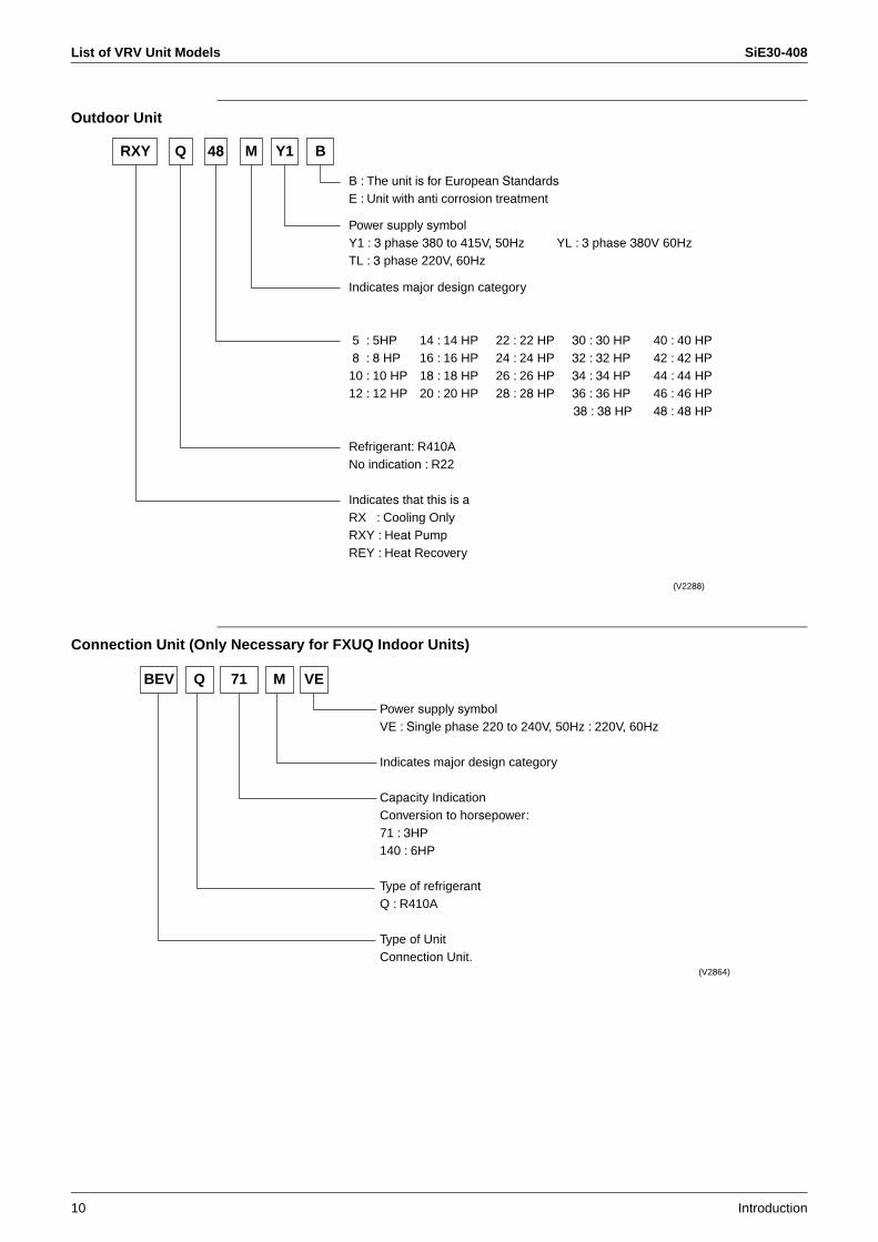
Outdoor Unit
Connection Unit (Only Necessary for FXUQ Indoor Units)
Y1
B : The unit is for European StandardsE : Unit with anti corrosion treatment
Power supply symbolY1 : 3 phase 380 to 415V, 50Hz YL : 3 phase 380V 60HzTL : 3 phase 220V, 60Hz
Indicates major design category
5 : 5HP 14 : 14 HP 22 : 22 HP 30 : 30 HP 40 : 40 HP8 : 8 HP 16 : 16 HP 24 : 24 HP 32 : 32 HP 42 : 42 HP10 : 10 HP 18 : 18 HP 26 : 26 HP 34 : 34 HP 44 : 44 HP12 : 12 HP 20 : 20 HP 28 : 28 HP 36 : 36 HP 46 : 46 HP
38 : 38 HP 48 : 48 HP
Refrigerant: R410ANo indication : R22
Indicates that this is aRX : Cooling OnlyRXY : Heat PumpREY : Heat Recovery
M B48QRXY
(V2288)
Power supply symbolVE : Single phase 220 to 240V, 50Hz : 220V, 60Hz
Indicates major design category
Capacity IndicationConversion to horsepower:71 : 3HP140 : 6HP
Type of refrigerantQ : R410A
Type of UnitConnection Unit.
BEV M VEQ 71
(V2864)
SiE30-408 System Basic Configuration
Introduction 11
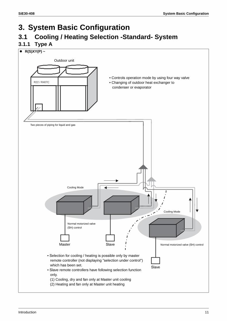
3. System Basic Configuration3.1 Cooling / Heating Selection -Standard- System3.1.1 Type A
R(S)XY(P) ~
Outdoor unit
Cooling Mode
Cooling Mode
R22 / R407C
Two pieces of piping for liquid and gas
Normal motorized valve (SH) controlMaster Slave
Slave
• Controls operation mode by using four way valve• Changing of outdoor heat exchanger to
condenser or evaporator
• Selection for cooling / heating is possible only by masterremote controller (not displaying "selection under control") which has been set.
• Slave remote controllers have following selection functiononly.
(1) Cooling, dry and fan only at Master unit cooling (2) Heating and fan only at Master unit heating
Normal motorized valve
(SH) control
System Basic Configuration SiE30-408
12 Introduction
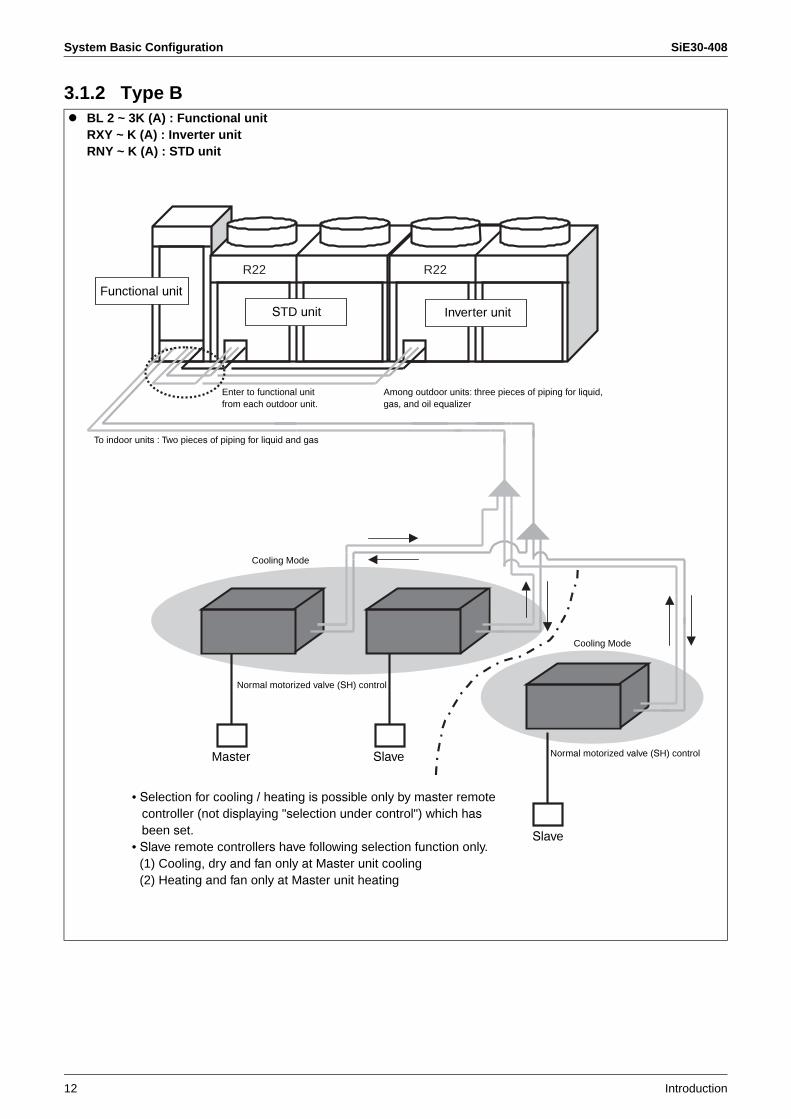
3.1.2 Type BBL 2 ~ 3K (A) : Functional unitRXY ~ K (A) : Inverter unitRNY ~ K (A) : STD unit
Functional unit
STD unit Inverter unit
To indoor units : Two pieces of piping for liquid and gas
Cooling Mode
Cooling Mode
Normal motorized valve (SH) control
Normal motorized valve (SH) controlMaster Slave
Slave
R22 R22
• Selection for cooling / heating is possible only by master remote controller (not displaying "selection under control") which hasbeen set.
• Slave remote controllers have following selection function only. (1) Cooling, dry and fan only at Master unit cooling (2) Heating and fan only at Master unit heating
Enter to functional unitfrom each outdoor unit.
Among outdoor units: three pieces of piping for liquid,gas, and oil equalizer

SiE30-408 System Basic Configuration
Introduction 13
3.1.3 Type CRX(Y)(Q) ~ M
Outdoor unit Outdoor unit
Cooling Mode
Outdoor unit
R410A or R22 R410A or R22 R410A or R22
Cooling Mode
Normal motorized valve (SH) controlMaster Slave
Slave
• Controls operation mode by usingfour way valve
• Changing of outdoor heatexchanger to condenser or evaporator
• Selection for cooling / heating is possible only by masterremote controller (not displaying "selection under control") which has been set.
• Slave remote controllers have following selection function only. (1) Cooling, dry and fan only at Master unit cooling (2) Heating and fan only at Master unit heating
Three pieces of piping for liquid, gas, and oil equalizer
Oil equalizer is installed only when outdoor VRV system is connected.
Normal motorized valve (SH) control
System Basic Configuration SiE30-408
14 Introduction
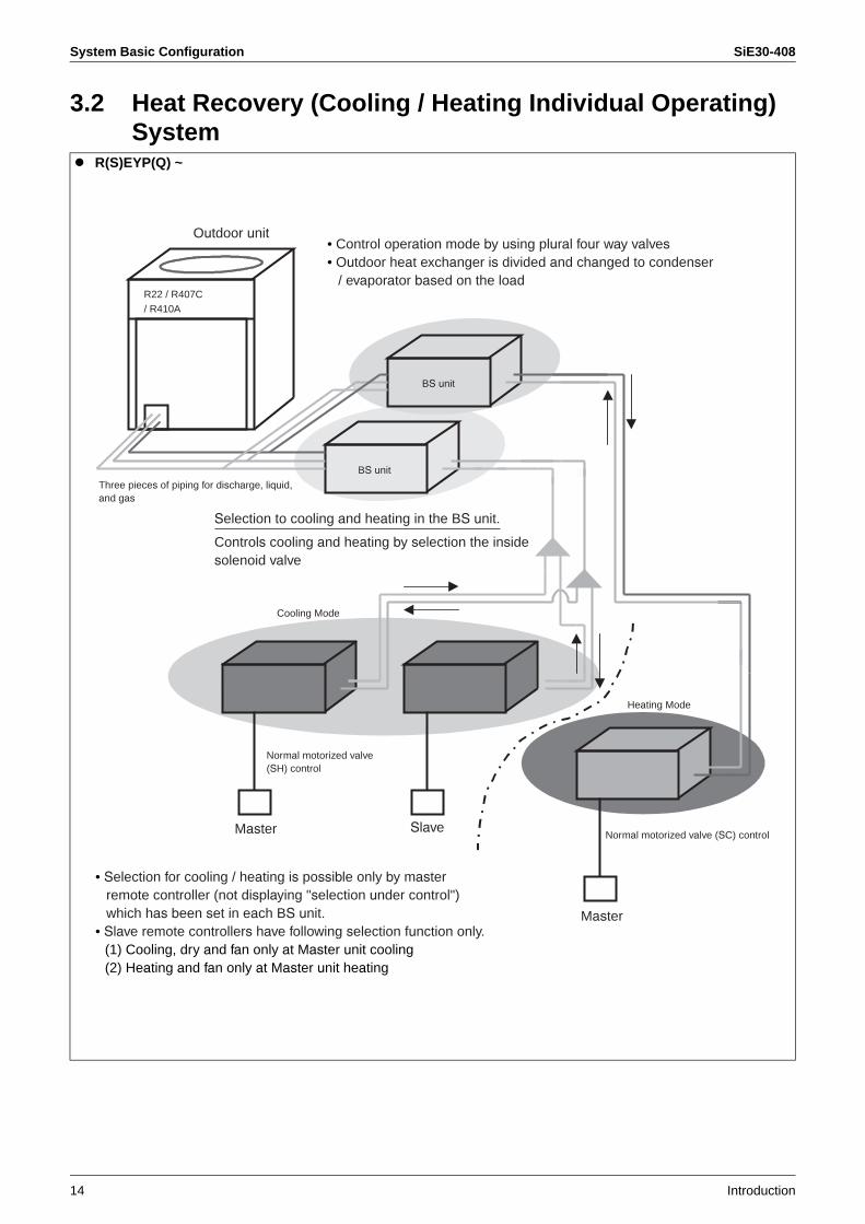
3.2 Heat Recovery (Cooling / Heating Individual Operating) System
R(S)EYP(Q) ~
Outdoor unit
Cooling Mode
Heating Mode
BS unit
BS unit
Normal motorized valve (SC) controlMaster Slave
Master
• Control operation mode by using plural four way valves• Outdoor heat exchanger is divided and changed to condenser
/ evaporator based on the load
• Selection for cooling / heating is possible only by masterremote controller (not displaying "selection under control") which has been set in each BS unit.
• Slave remote controllers have following selection function only. (1) Cooling, dry and fan only at Master unit cooling (2) Heating and fan only at Master unit heating
R22 / R407C / R410A
Three pieces of piping for discharge, liquid,and gas
Controls cooling and heating by selection the insidesolenoid valve
Selection to cooling and heating in the BS unit.
Normal motorized valve (SH) control
SiE30-408 Super Wiring System
Introduction 15
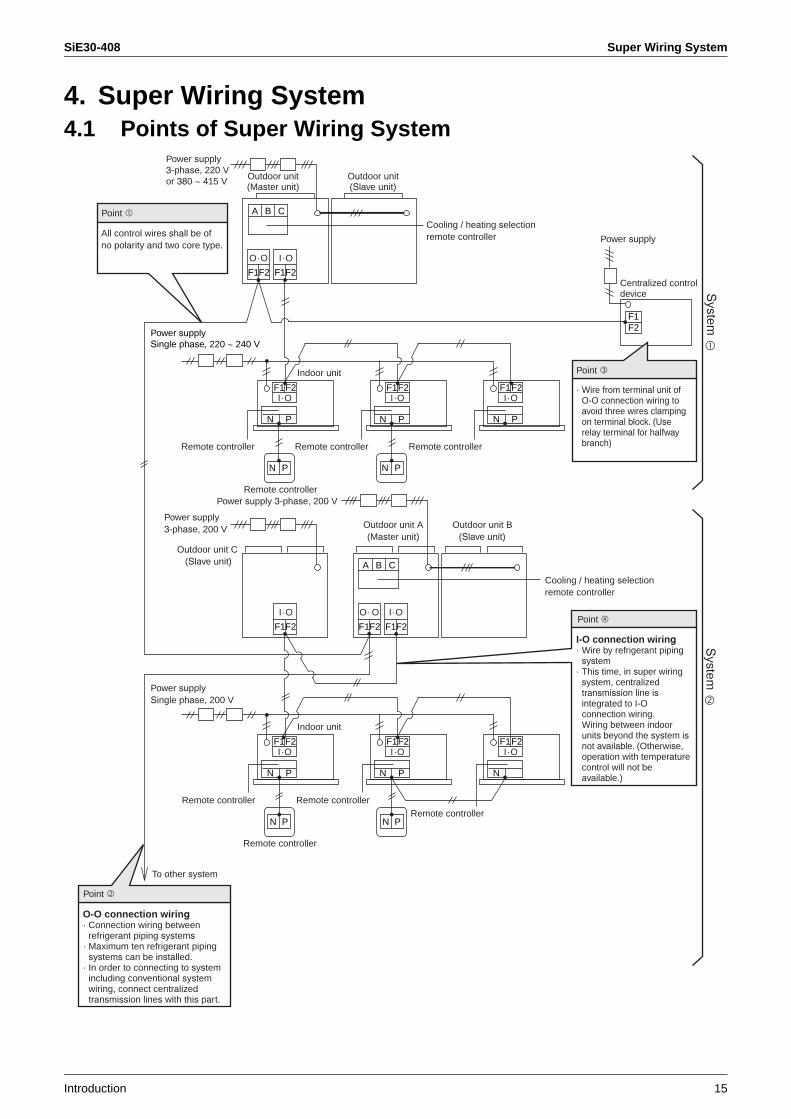
4. Super Wiring System4.1 Points of Super Wiring System
Point
All control wires shall be of no polarity and two core type.
Point
Point
O-O connection wiring· Connection wiring between
refrigerant piping systems· Maximum ten refrigerant piping
systems can be installed.· In order to connecting to system
including conventional systemwiring, connect centralized transmission lines with this part.
A B C
F1F2
O · O
F1F2
I · O
F1F2I · O
F1F2
F1F2 F1F2
Power supply
Point
N
N P
P
Indoor unit
Remote controller
F1F2I · O
N
N P
P
F1F2I · O
N P
F1I · O
N
N P
Indoor unit
Remote controller
A B C
O· O I · O
F1F2
I · O
Power supply 3-phase, 200 V
F1F2F2I · O
N
N P
PP
F1F2I · O
N
System
To other system
Remote controller Remote controller Remote controller
· Wire from terminal unit of O-O connection wiring to avoid three wires clampingon terminal block. (Userelay terminal for halfwaybranch)
I-O connection wiring· Wire by refrigerant piping
system· This time, in super wiring
system, centralized transmission line isintegrated to I-O connection wiring.
Wiring between indoor units beyond the system isnot available. (Otherwise, operation with temperaturecontrol will not beavailable.)
Remote controller Remote controllerRemote controller
System
Power supply3-phase, 220 V or 380 ~ 415 V Outdoor unit
(Master unit)Outdoor unit(Slave unit)
Cooling / heating selectionremote controller
Power supplySingle phase, 220 ~ 240 V
Power supply3-phase, 200 V
Outdoor unit C (Slave unit)
Outdoor unit A (Master unit)
Outdoor unit B (Slave unit)
Power supplySingle phase, 200 V
Centralized control device
Cooling / heating selectionremote controller
Super Wiring System SiE30-408
16 Introduction
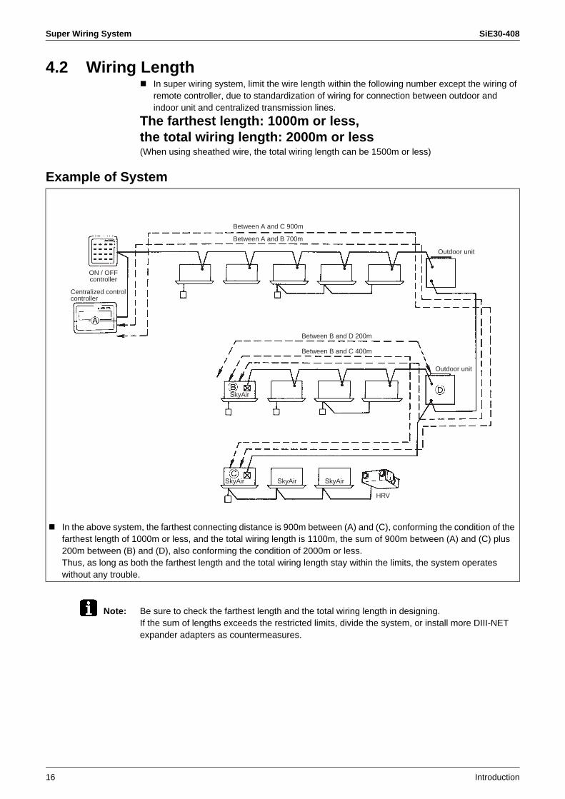
4.2 Wiring LengthIn super wiring system, limit the wire length within the following number except the wiring of remote controller, due to standardization of wiring for connection between outdoor and indoor unit and centralized transmission lines.
The farthest length: 1000m or less, the total wiring length: 2000m or less(When using sheathed wire, the total wiring length can be 1500m or less)
Example of System
Note: Be sure to check the farthest length and the total wiring length in designing.If the sum of lengths exceeds the restricted limits, divide the system, or install more DIII-NET expander adapters as countermeasures.
In the above system, the farthest connecting distance is 900m between (A) and (C), conforming the condition of the farthest length of 1000m or less, and the total wiring length is 1100m, the sum of 900m between (A) and (C) plus 200m between (B) and (D), also conforming the condition of 2000m or less.Thus, as long as both the farthest length and the total wiring length stay within the limits, the system operates without any trouble.
ON / OFF controller
Centralized control controller
Between A and C 900m
Between A and B 700m
Between B and D 200m
Between B and C 400m
Outdoor unit
Outdoor unit
SkyAirSkyAirSkyAir
SkyAir
HRV

SiE30-408 REFNET Piping
Introduction 17
5. REFNET Piping5.1 Allowable Length of Refrigerant Piping5.1.1 For RSXY(P) ~ KA(L)
Allowable Length of Refrigerant Piping (Actual length)
Allowable Level Difference
Notes: 1. Be sure to use REFNET piping materials for piping branch part.2. Do not make branch part after branching with REFNET header.
Outdoor unit (master) to Outdoor unit (slave) [a] #1 branch kit to Indoor unit [c] Outdoor unit to Indoor unit (b + c)
Allowable length (m) 5m or less 40m or less 120m or less
Between outdoor unit and indoor unit [H1] Between indoor units [H2]
Between outdoor units (master and slave units) [H3]
Allowable level difference (m)
50m or lessIf outdoor unit is located lower than indoor unit: 40m or less 15m or less 5m or less
H1
H3
H2
c
b
a
Outdoor unit (Master unit)
Outdoor unit (Slave unit)
Indoor units
Indoor units
Indoor units
#1 refrigerant branch kit
REFNET header

REFNET Piping SiE30-408
18 Introduction
5.1.2 For RX(Y)(Q) ~ M
Allowable Length of Refrigerant Piping (Actual Length)
Allowable Level Difference
Notes: 1. Be sure to use REFNET piping materials for piping branch part.2. Do not make branch part after branching with REFNET header.
H1
H3
H2
c
a
Outdoor unit 1
Outdoor unit 2
Indoor units
Indoor units
Indoor units
#1 refrigerant branch kit
Outdoor branch kit
b
REFNET header
Outdoor branch to Outdoor unit [a] #1 branch kit to idoor unit [c] Outdoor branch to Indoor unit [b + c]
Allowable length (m) 10m or less 40m or less 150m or less
Between outdoor unit and indoor unit [H1] Between indoor units [H2] Between outdoor units [H3]
Allowable level difference (m)
50m or lessIf outdoor unit is located lower than indoor unit: 40m or less 15m or less 5m or less

SiE30-408 REFNET Piping
Introduction 19
5.2 For Refrigerant PipingGuideline for Tightening Flare Nut (When No Torque Wrench is Available.)
Notes: 1. When pipe jointing with flare nut, use both open-ended spanner and a torque wrench.2. If no torque wrench is available, refer to the following item 3 as a guide.3. In the work of tightening flare nut, there should be a spot where the tightening torque
suddenly increases. Thereafter, tighten further with tightening angle shown in above list.
Bending Radius in Pipe and Flare Tightening Torque
Processing Dimension for Flare Section
Calculation List on Equivalent Length of Joint (For Reference) Unit: m
Piping size Tightening angle (guideline) Recommended arm length of tool
φ6.4 60º ~ 90º Approximately 150mm
φ9.5 60º ~ 90º Approximately 200mm
φ12.7 30º ~ 60º Approximately 250mm
φ15.9 30º ~ 60º Approximately 300mm
φ19.1 20º ~ 35º Approximately 450mm
Piping size Bending radius Tightening torque (N·cm)
φ6.4 30 to 40 mm 1420 ~ 1720
φ9.5 30 to 40 mm 3270 ~ 3990
φ12.7 40 to 60 mm 4950 ~ 6030
φ15.9 40 to 60 mm 6180 ~ 7540
φ19.1 — 9720 ~ 11860
Piping sizeDimension-A
Flared shapeR22, R407C For R410A
φ6.4 8.6 ~ 9.0 8.7 ~ 9.1
φ9.5 12.6 ~ 13.0 12.8 ~ 13.2
φ12.7 15.8 ~ 16.2 16.2 ~ 16.6
φ15.9 19.0 ~ 19.4 19.3 ~ 19.7
φ19.1 23.3 ~ 23.7 (24)
Pipe diameterType φ6.4 φ9.5 φ12.7 φ15.9 φ19.1 φ25.4 φ31.8
L joint
0.16 0.18 0.20 0.25 0.35 0.45 0.55
Trap bend
1.4 1.3 1.5 2.0 2.4 3.4 4.0
REFNET joint
0.5
REFNET header
1.0
R0.4~0.8
90°
2°
45°
2°

REFNET Piping SiE30-408
20 Introduction

SiE30-408
Basic Information 21
1. Explanations on P-H Diagram (Refrigerant Characteristics Table).......222. Concept of Basic Refrigeration Cycle ...................................................233. Points of Refrigerant Control of VRV System .......................................24
3.1 Cooling Operation ..................................................................................243.2 Heating Operation ..................................................................................253.3 Compressor Capacity Control ................................................................263.4 Control of Electronic Expansion Valve ...................................................27
4. Control of Indoor Unit ............................................................................284.1 Thermostat-control .................................................................................284.2 Drain Pump Control................................................................................304.3 Freeze-up Prevention Control ................................................................314.4 Heater Control ........................................................................................324.5 Thermostat Control in Cooling / Heating Automatic Operation ..............33
5. Other Functional Operations .................................................................355.1 Explanations on Main Functional Control...............................................355.2 Explanations on Electric and Functional Components ...........................36

Explanations on P-H Diagram (Refrigerant Characteristics Table) SiE30-408
22 Basic Information
1. Explanations on P-H Diagram (Refrigerant Characteristics Table)
P-H diagram shows characteristics of various refrigerants with pressure on vertical axis and enthalpy on horizontal axis.
Change of state change from gas to liquid is said condensation and that from liquid to gas said evaporation. The boundary state of each change is said saturation, and the temperature generating saturation is said saturation temperature.Saturation temperature depends on kinds of refrigerant and pressure. The characteristics of saturation temperature are shown on P-H diagrams of various refrigerants, which is called saturation curve.The characteristics of temperature gradients for pressure and enthalpy are shown on P-H diagrams, which is called "isothermal lines". By knowing the zone divided with saturation curve in which the intersection point of pressure and isothermal line is included, the information on the state of refrigerant can be provided. The intersection above can be obtained by measuring pressure and temperature of refrigerant at a certain point.As to single refrigerants (R22, R134A etc.), isothermal line has no gradient in the saturated area ,that is, the saturation temperature under certain pressure is same at both liquid side and gas side. As to mixed refrigerants (R407C, R410A etc.), in which plural refrigerants with different boiling points are mixed, their isothermal lines have gradients in the saturated area, so the saturation temperatures under certain pressure are different at liquid side and gas side. They are called zeotropic refrigerants, with the exception that R410A is called false azeotropic refrigerant.
States of refrigerants are classified following 3 categories.Superheated vapor: state that refrigerant is existing as gasSaturated vapor: state that is mixture of liquid and gas (this is also called wet vapor)Subcooled liquid: state that refrigerant is existing as liquid
Isothermal line
Saturation curve
Enthalpy h (KJ . kg-1)
Pre
ssur
e
P(M
Pa)
Saturated area(Saturated vapor)
Subcooled area(Subcooled liquid)
Superheated area(Superheated vapor)
Zeotropic refrigerant R407C has different saturation points atliquid side and gas side. (gas side is higher than liquid side)
SiE30-408 Concept of Basic Refrigeration Cycle
Basic Information 23
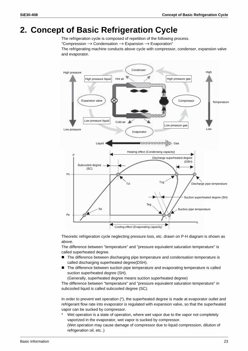
2. Concept of Basic Refrigeration CycleThe refrigeration cycle is composed of repetition of the following process."Compression → Condensation → Expansion → Evaporation" The refrigerating machine conducts above cycle with compressor, condenser, expansion valve and evaporator.
Theoretic refrigeration cycle neglecting pressure loss, etc. drawn on P-H diagram is shown as above.The difference between "temperature" and "pressure equivalent saturation temperature" is called superheated degree.
The difference between discharging pipe temperature and condensation temperature is called discharging superheated degree(DSH).The difference between suction pipe temperature and evaporating temperature is called suction superheated degree (SH).(Generally, superheated degree means suction superheated degree)
The difference between "temperature" and "pressure equivalent saturation temperature" in subcooled liquid is called subcooled degree (SC).
In order to prevent wet operation (*), the superheated degree is made at evaporator outlet and refrigerant flow rate into evaporator is regulated with expansion valve, so that the superheated vapor can be sucked by compressor.* Wet operation is a state of operation, where wet vapor due to the vapor not completely
vaporized in the evaporator, wet vapor is sucked by compressor.(Wet operation may cause damage of compressor due to liquid compression, dilution of refrigeration oil, etc..)
Condenser
Hot air
Cold air
P
Pc
Pe
Tcl Tcg
h
Tel
Teg
High pressure liquid
Low pressure liquid
Discharge pipe temperature
Suction superheated degree (SH)
Suction pipe temperature
Cooling effect (Evaporating capacity)
GasLiquid
Heating effect (Condensing capacity)
High
Low
High pressure
Low pressure
Temperature
Low pressure gas
Compressor
High pressure gas
Evaporator
Expansion valve
Discharge superheated degree (DSH)
Subcooled degree (SC)
Points of Refrigerant Control of VRV System SiE30-408
24 Basic Information
3. Points of Refrigerant Control of VRV System3.1 Cooling Operation
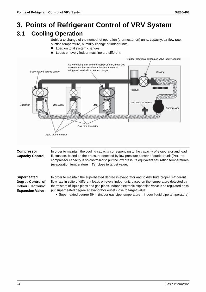
Subject to change of the number of operation (thermostat-on) units, capacity, air flow rate, suction temperature, humidity change of indoor units
Load on total system changes.Loads on every indoor machine are different.
Compressor Capacity Control
In order to maintain the cooling capacity corresponding to the capacity of evaporator and load fluctuation, based on the pressure detected by low pressure sensor of outdoor unit (Pe), the compressor capacity is so controlled to put the low pressure equivalent saturation temperatures (evaporation temperature = Te) close to target value.
Superheated Degree Control of Indoor Electronic Expansion Valve
In order to maintain the superheated degree in evaporator and to distribute proper refrigerant flow rate in spite of different loads on every indoor unit, based on the temperature detected by thermistors of liquid pipes and gas pipes, indoor electronic expansion valve is so regulated as to put superheated degree at evaporator outlet close to target value.
• Superheated degree SH = (indoor gas pipe temperature – indoor liquid pipe temperature)
Superheated degree control
Outdoor electronic expansion valve is fully opened.
Cooling
Compressor
Receiver
Low pressure sensor
Gas pipe themistor
Liquid pipe themistor
Operation Operation Stop
As to stopping unit and thermostat-off unit, motorized valve should be closed completely not to sendrefrigerant into indoor heat exchanger.
SiE30-408 Points of Refrigerant Control of VRV System
Basic Information 25
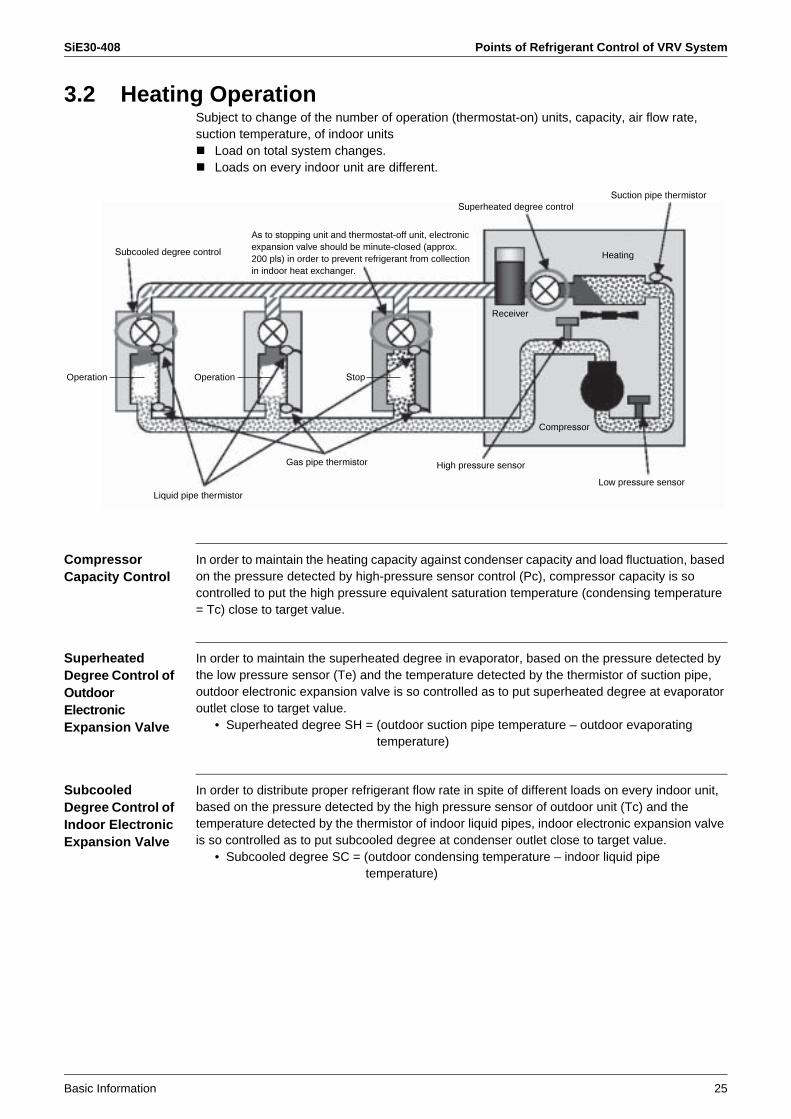
3.2 Heating OperationSubject to change of the number of operation (thermostat-on) units, capacity, air flow rate, suction temperature, of indoor units
Load on total system changes.Loads on every indoor unit are different.
Compressor Capacity Control
In order to maintain the heating capacity against condenser capacity and load fluctuation, based on the pressure detected by high-pressure sensor control (Pc), compressor capacity is so controlled to put the high pressure equivalent saturation temperature (condensing temperature = Tc) close to target value.
Superheated Degree Control of Outdoor ElectronicExpansion Valve
In order to maintain the superheated degree in evaporator, based on the pressure detected by the low pressure sensor (Te) and the temperature detected by the thermistor of suction pipe, outdoor electronic expansion valve is so controlled as to put superheated degree at evaporator outlet close to target value.
• Superheated degree SH = (outdoor suction pipe temperature – outdoor evaporating temperature)
Subcooled Degree Control of Indoor Electronic Expansion Valve
In order to distribute proper refrigerant flow rate in spite of different loads on every indoor unit, based on the pressure detected by the high pressure sensor of outdoor unit (Tc) and the temperature detected by the thermistor of indoor liquid pipes, indoor electronic expansion valve is so controlled as to put subcooled degree at condenser outlet close to target value.
• Subcooled degree SC = (outdoor condensing temperature – indoor liquid pipe temperature)
Subcooled degree control
Superheated degree controlSuction pipe thermistor
Heating
Compressor
Low pressure sensor
Receiver
High pressure sensorGas pipe thermistor
Liquid pipe thermistor
As to stopping unit and thermostat-off unit, electronic expansion valve should be minute-closed (approx. 200 pls) in order to prevent refrigerant from collection in indoor heat exchanger.
Operation Operation Stop
Points of Refrigerant Control of VRV System SiE30-408
26 Basic Information
3.3 Compressor Capacity Control
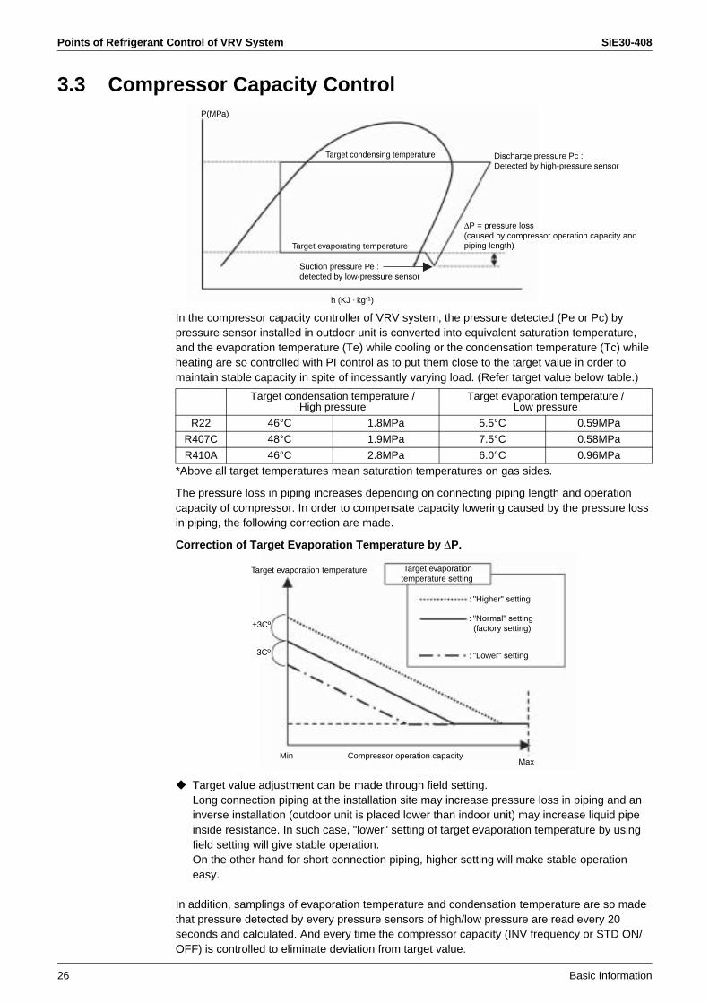
In the compressor capacity controller of VRV system, the pressure detected (Pe or Pc) by pressure sensor installed in outdoor unit is converted into equivalent saturation temperature, and the evaporation temperature (Te) while cooling or the condensation temperature (Tc) while heating are so controlled with PI control as to put them close to the target value in order to maintain stable capacity in spite of incessantly varying load. (Refer target value below table.)
*Above all target temperatures mean saturation temperatures on gas sides.
The pressure loss in piping increases depending on connecting piping length and operation capacity of compressor. In order to compensate capacity lowering caused by the pressure loss in piping, the following correction are made.
Correction of Target Evaporation Temperature by ∆P.
Target value adjustment can be made through field setting.Long connection piping at the installation site may increase pressure loss in piping and an inverse installation (outdoor unit is placed lower than indoor unit) may increase liquid pipe inside resistance. In such case, "lower" setting of target evaporation temperature by using field setting will give stable operation.On the other hand for short connection piping, higher setting will make stable operation easy.
In addition, samplings of evaporation temperature and condensation temperature are so made that pressure detected by every pressure sensors of high/low pressure are read every 20 seconds and calculated. And every time the compressor capacity (INV frequency or STD ON/OFF) is controlled to eliminate deviation from target value.
P(MPa)
Target condensing temperature
Target evaporating temperature
h (KJ . kg-1)
Suction pressure Pe : detected by low-pressure sensor
∆P = pressure loss(caused by compressor operation capacity andpiping length)
Discharge pressure Pc : Detected by high-pressure sensor
Target condensation temperature / High pressure
Target evaporation temperature / Low pressure
R22 46°C 1.8MPa 5.5°C 0.59MPa
R407C 48°C 1.9MPa 7.5°C 0.58MPa
R410A 46°C 2.8MPa 6.0°C 0.96MPa
Target evaporation temperature
Compressor operation capacity
: "Higher" setting
: "Normal" setting (factory setting)
: "Lower" setting
MaxMin
+3Cº
–3Cº
Target evaporationtemperature setting

SiE30-408 Points of Refrigerant Control of VRV System
Basic Information 27
3.4 Control of Electronic Expansion Valve
Electronic Expansion Valve of Outdoor Unit
In Cooling OperationIn cooling operation, outdoor electronic expansion valve should basically be fully open.Note: In some models of type L or newer, the valve can be fully closed with a bridge circuit.
In Heating Operation = Superheated Degree ControlSuperheated degree [SH] is calculated from the low pressure equivalent saturation temperature (Te) converted from the pressure detected by the low pressure sensor of outdoor unit (Pe) and temperature detected by suction pipe thermistor (Te). Electronic expansion valve opening degree is so regulated that the superheated degree [SH] becomes close to targeted superheated degree [SHS].
When SH > SHS, adjust to make opening degree wider than present one.When SH < SHS, adjust to make opening degree narrower than present one.
SH : Superheated degree (Ts – Te)SHS : Target superheated degree (Normally 5°C)
Electronic Expansion Valve of Indoor Unit
In Cooling Operation = Superheated Degree ControlSuperheated degree [SH] is calculated from temperature detected by the gas pipe thermistor of indoor machine (Tg) and the temperature detected by liquid pipe thermistor (Tl). Electronic expansion valve opening degree is so controlled that the superheated degree [SH] becomes close to targeted superheated degree [SHS].The compensation is made based on the temperature difference between setting temperature and suction air thermistor temperature (∆T).
When SH > SHS, adjust to make opening degree wider than the present one.When SH < SHS, adjust to make opening degree narrower than the present one.
SH : Superheated degree (Tg – Tl)SHS : Target superheated degree
[Normally 5°C, however, when the temperature difference (∆T) decreases, SHS increases. (even when SH is large, the opening degree becomes small.)]
∆T : Remote controller setting temperature - suction air thermistor detection value
Subcooled Degree Control in Heating OperationSubcooled degree [SC] is calculated from the high pressure equivalent saturation temperature (Tc) converted from the pressure detected by high pressure sensor of outdoor unit and the temperature detected by liquid pipe thermistor of indoor unit (Tl). Electronic expansion valve opening degree is so regulated that the subcooled degree [SC] is close to target subcooled degree [SCS].The compensation is made based on the temperature difference between setting temperature and suction air thermistor temperature (∆T).
When SC > SCS, adjust so to make opening degree wider than present one.When SC < SCS, adjust so to make opening degree narrower than present one.
SC : Superheated degree (Tc – Tl)SCS : Target subcooled degree.
[Normally 5°C, however, when the temperature difference (∆T) decreases, SCS increases. (even when SC is large, the opening degree becomes small.)]
∆T : Remote controller setting temperature - suction air thermistor detection value
(Reference) Control range of outdoor electronic expansion valve• R22 unit ... 0 to 2000pls• R407C unit ...
1 Ve-up standard (RSXYP 5 to 10L): 0 to 480 pls2 Others: 0 to 2000 pls
• R410 A unit ... 0 to 1400 pls

Control of Indoor Unit SiE30-408
28 Basic Information
4. Control of Indoor Unit4.1 Thermostat-control4.1.1 Operation Range of Remote Controller Thermostat
Room temperature is controlled by remote controller thermostat side and suction thermostat (body-thermostat) on indoor unit side.(However, when remote controller thermostat is set to "Not used " with field setting, the unit can be controlled only by body-thermostat.)
Note: When the outdoor air (OA) mixed with indoor air is sucked, the room temperature may happen to be out of the set temperature because the air temperature is out of the area of "operation range of remote controller thermostat ". In such a case, install the remote controller thermostat in the room where there is no influence of outdoor air.
Suction temperature (TH1)
12 14 16 18 20 22 24 26 28 30 32 34
12 14 16 18 20 22 24 26 28 30 32 34
20
22
24
26
28
30
32
34
16
15
18
20
22
24
26
28
30
Suction temperature (TH1)
Range in which body-thermostat can be used
Differential
In cooling operation
In heating operation
Switching point between remote controller thermostat and body-thermostat
Range in which remote controller thermostatcan be used
Preset temperature(TS)
Preset temperature(TS)
Body-thermostat Body-thermostat
Body-thermostat Body-thermostat
Body-thermostat Body-thermostat
Body-thermostat Body-thermostat
Remote controller thermostat
Remote controller thermostat
Remote controller thermostat

SiE30-408 Control of Indoor Unit
Basic Information 29
4.1.2 Thermostat-control in Normal OperationAs to VRV system, remote controller thermostat is set to use when shipped from factory. Normally thermostat differential is set to setting temperature –1°C at cooling, while set to setting temperature +1°C in heating when shipped from factory.
However, the unit can be controlled only by body-thermostat when using 1 group remote controller. For cassette type indoor unit, the unit is controlled with compensation value of –2°C against body-thermostat detection value in heating operation. (Thermostat - differential can be changed from 1°C to 0.5°C with field setting. Refer to page 43 and page 44 for changing.)
4.1.3 Thermostat - control in Dry OperationIn dry operation, control is made based on suction temperature at the time of operation start.
Fan is driven with L flow rate during dry operation, and turned off for a period of 6 minutes during thermostat-off, and then with L flow rate. (In order to prevent humidity from rising in the room during thermostat-off.)
In cooling operation
In heating operation
Tr : Temperature detected by suctionair thermistor (R1T)
Normal operation Thermostat OFF
Tr < Preset temperature –1°C
Normal operation Thermostat OFF
Tr > Preset temperature +1°C
When Tro ≤ 24.5°C Tro : Suction air temperature at dry operation start
When Tro > 24.5°C Tr : Temperature detected by suction air thermistor (R1T)
In dry operation Thermostat OFF
In dry operation Thermostat OFF
Tr<Tro –1°C
Tr<Tro –1.5°C
Control of Indoor Unit SiE30-408
30 Basic Information
4.2 Drain Pump Control4.2.1 Drain Pump Control
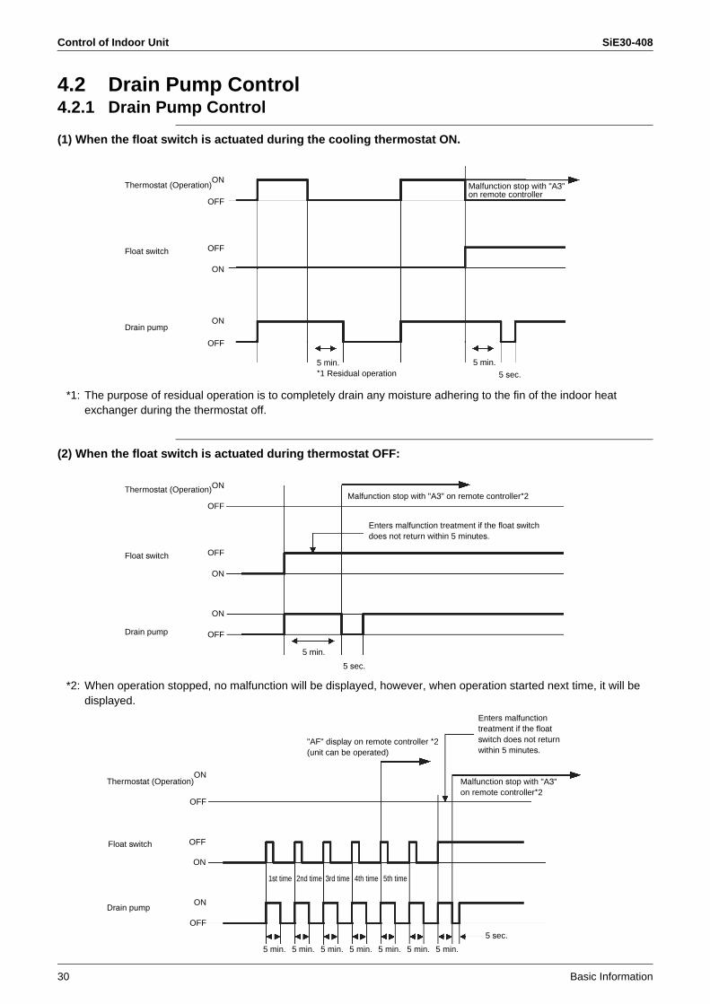
(1) When the float switch is actuated during the cooling thermostat ON.
*1: The purpose of residual operation is to completely drain any moisture adhering to the fin of the indoor heat exchanger during the thermostat off.
(2) When the float switch is actuated during thermostat OFF:
*2: When operation stopped, no malfunction will be displayed, however, when operation started next time, it will be displayed.
Thermostat (Operation)
Float switch
Drain pump
5 min.
5 sec.
ON
OFF
ON
OFF
ON
OFF
5 min.*1 Residual operation
Malfunction stop with "A3"on remote controller
Thermostat (Operation)
Float switch
Drain pump
5 min.
5 sec.
ON
OFF
ON
OFF
ON
OFF
Malfunction stop with "A3" on remote controller*2
Enters malfunction treatment if the float switchdoes not return within 5 minutes.
5 min. 5 min. 5 min. 5 min. 5 min. 5 min. 5 min.
1st time 2nd time 3rd time 4th time 5th time
5 sec.
ON
OFF
ON
OFF
ON
OFF
Enters malfunctiontreatment if the floatswitch does not return within 5 minutes.
Thermostat (Operation)
Float switch
Drain pump
"AF" display on remote controller *2(unit can be operated)
Malfunction stop with "A3"on remote controller*2
SiE30-408 Control of Indoor Unit
Basic Information 31
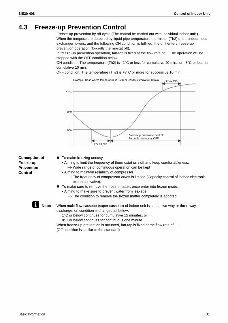
4.3 Freeze-up Prevention ControlFreeze-up prevention by off-cycle (The control be carried out with individual indoor unit.)When the temperature detected by liquid pipe temperature thermistor (Th2) of the indoor heat exchanger lowers, and the following ON condition is fulfilled, the unit enters freeze-up prevention operation (forcedly thermostat off).In freeze-up prevention operation, fan-tap is fixed at the flow rate of L. The operation will be stopped with the OFF condition below.ON condition: The temperature (Th2) is –1°C or less for cumulative 40 min., or –5°C or less for cumulative 10 min.OFF condition: The temperature (Th2) is +7°C or more for successive 10 min.
Conception of Freeze-upPrevention Control
To make freezing uneasy• Aiming to limit the frequency of thermostat on / off and keep comfortableness.
→ Wide range of continuous operation can be kept• Aiming to maintain reliability of compressor
→ The frequency of compressor on/off is limited (Capacity control of indoor electronic expansion valve).
To make sure to remove the frozen matter, once enter into frozen mode.• Aiming to make sure to prevent water from leakage
→ The condition to remove the frozen matter completely is adopted.
Note: When multi-flow cassette (super cassette) of indoor unit is set as two-way or three-way discharge, on condition is changed as below:
1°C or below continues for cumulative 15 minutes, or0°C or below continues for continuous one minute
When freeze-up prevention is actuated, fan-tap is fixed at the flow rate of LL.(Off condition is similar to the standard)
–5°C
0°C
+7°C
Example: Case where temperature is –5°C or less for cumulative 10 min. For 10 min.
For 10 min.
Freeze-up prevention control Forcedly thermostat OFF
Control of Indoor Unit SiE30-408
32 Basic Information
4.4 Heater Control4.4.1 Heater Control of VRV System
Optional heater (wiring modification adapter is required) is made on/off under the conditions below.
On Condition (All Conditions should be Satisfied)
Heating mode & thermostat-onNot under hot-startingNot under preparation of oil-return or defrostingNot under pressure equalizingTc (High pressure equivalent saturation temperature transmitted from outdoor) < 50°CTh2 (Indoor liquid pipe thermistor) < 43°C
Off Condition (Any One of the Conditions below should be Satisfied.)
Becomes any mode except heatingThermostat-offUnder hot-startingUnder preparation of oil-return or defrostingUnder pressure equalizingTc > 60°CTh2 > 47°C
4.4.2 Fan Residual OperationIn order to prevent the thermal protector from actuation during heater is off, the fan will be operated with residual operation for the certain period of time after heater is off. (This operation shall be carried out regardless of heater)
Residual operation time = Ceiling suspended type: 100 seconds, others: 60 seconds
SiE30-408 Control of Indoor Unit
Basic Information 33
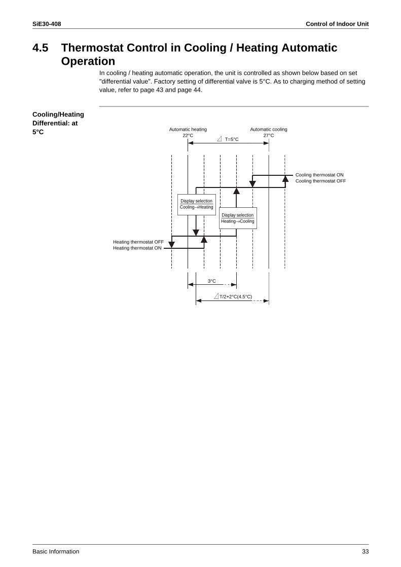
4.5 Thermostat Control in Cooling / Heating Automatic Operation
In cooling / heating automatic operation, the unit is controlled as shown below based on set "differential value". Factory setting of differential valve is 5°C. As to charging method of setting value, refer to page 43 and page 44.
Cooling/Heating Differential: at 5°C
3°C
T=5°C
T/2+2°C(4.5°C)
Cooling / heating differential : at 3°C
Automatic heating22°C
Automatic cooling25°C
T=3°C
Automatic heating22°C
Automatic cooling 27°C
Display selectionCooling→Heating
Display selectionHeating→Cooling
Cooling thermostat ONCooling thermostat OFF
Heating thermostat OFFHeating thermostat ON

Control of Indoor Unit SiE30-408
34 Basic Information
Cooling/Heating Differential: at 3°C
Cooling/Heating Differential: at 0°C
In order to prevent hunting in cooling / heating:After cooling operation thermostat turns off, if the temperature does not reach setting temperature –2°C, heating operation should not be on.After heating operation thermostat turns off, if the temperature does not reach setting temperature +3°C, cooling operation should not be on.
3°C
T=3°C
T/2+2°C(3.5°C)
Automatic cooling 25°C
Automatic heating22°C
Cooling thermostat ONCooling thermostat OFF
Heating thermostat OFF Heating thermostat ON
Display selectionCooling→Heating
Display selectionHeating→Cooling
3°C
T/2+2°C(2°C)
Automatic heating / cooling 25°C
Cooling thermostat ONCooling thermostat OFF
Heating thermostat OFFHeating thermostat ON
Display selectionCooling→Heating
Display selectionHeating→Cooling
SiE30-408 Other Functional Operations
Basic Information 35
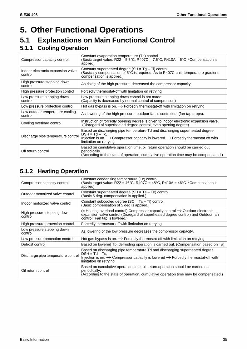
5. Other Functional Operations5.1 Explanations on Main Functional Control5.1.1 Cooling Operation
5.1.2 Heating Operation
Compressor capacity controlConstant evaporation temperature (Te) control(Basic target value: R22 = 5.5°C, R407C = 7.5°C, R410A = 6°C *Compensation is applied)
Indoor electronic expansion valve control
Constant superheated degree (SH = Tg – Tl) control(Basically compensation of 5°C is required. As to R407C unit, temperature gradient compensation is applied.)
High pressure stepping down control As rising of the high pressure, decreased the compressor capacity.
High pressure protection control Forcedly thermostat-off with limitation on retrying
Low pressure stepping down control
Low pressure stepping down control is not made.(Capacity is decreased by normal control of compressor.)
Low pressure protection control Hot gas bypass is on. → Forcedly thermostat-off with limitation on retrying
Low outdoor temperature cooling control As lowering of the high pressure, outdoor fan is controlled. (fan-tap drops).
Cooling overload control Instruction of forcedly opening degree is given to indoor electronic expansion valve. (Disregard of superheated degree control, even opening degree)
Discharge pipe temperature control
Based on discharging pipe temperature Td and discharging superheated degree DSH = Td – Tc,Injection is on. → Compressor capacity is lowered.→ Forcedly thermostat off with limitation on retrying
Oil return controlBased on cumulative operation time, oil return operation should be carried out periodically.(According to the state of operation, cumulative operation time may be compensated.)
Compressor capacity controlConstant condensing temperature (Tc) control(Basic target value: R22 = 46°C, R407C = 48°C, R410A = 46°C *Compensation is applied)
Outdoor motorized valve control Constant superheated degree (SH = Ts – Te) control(Basic 5 deg. compensation is applied.)
Indoor motorized valve control Constant subcooled degree (SC = Tc – Tl) control (Basic compensation of 5 deg is applied.)
High pressure stepping down control
(= Heating overload control) Compressor capacity control → Outdoor electronic expansion valve control (Disregard of superheated degree control) and Outdoor fan control (Fan tap is lowered.)
High pressure protection control Forcedly thermostat-off with limitation on retrying
Low pressure stepping down control As lowering of the low pressure decreases the compressor capacity.
Low pressure protection control Hot gas bypass is on. → Forcedly thermostat-off with limitation on retrying
Defrost control Based on lowered Tb, defrosting operation is carried out. (Compensation based on Ta).
Discharge pipe temperature control
Based on discharging pipe temperature Td and discharging superheated degree DSH = Td – Tc,Injection is on. → Compressor capacity is lowered → Forcedly thermostat-off with limitation on retrying
Oil return controlBased on cumulative operation time, oil return operation should be carried out periodically.(According to the state of operation, cumulative operation time may be compensated.)
Other Functional Operations SiE30-408
36 Basic Information
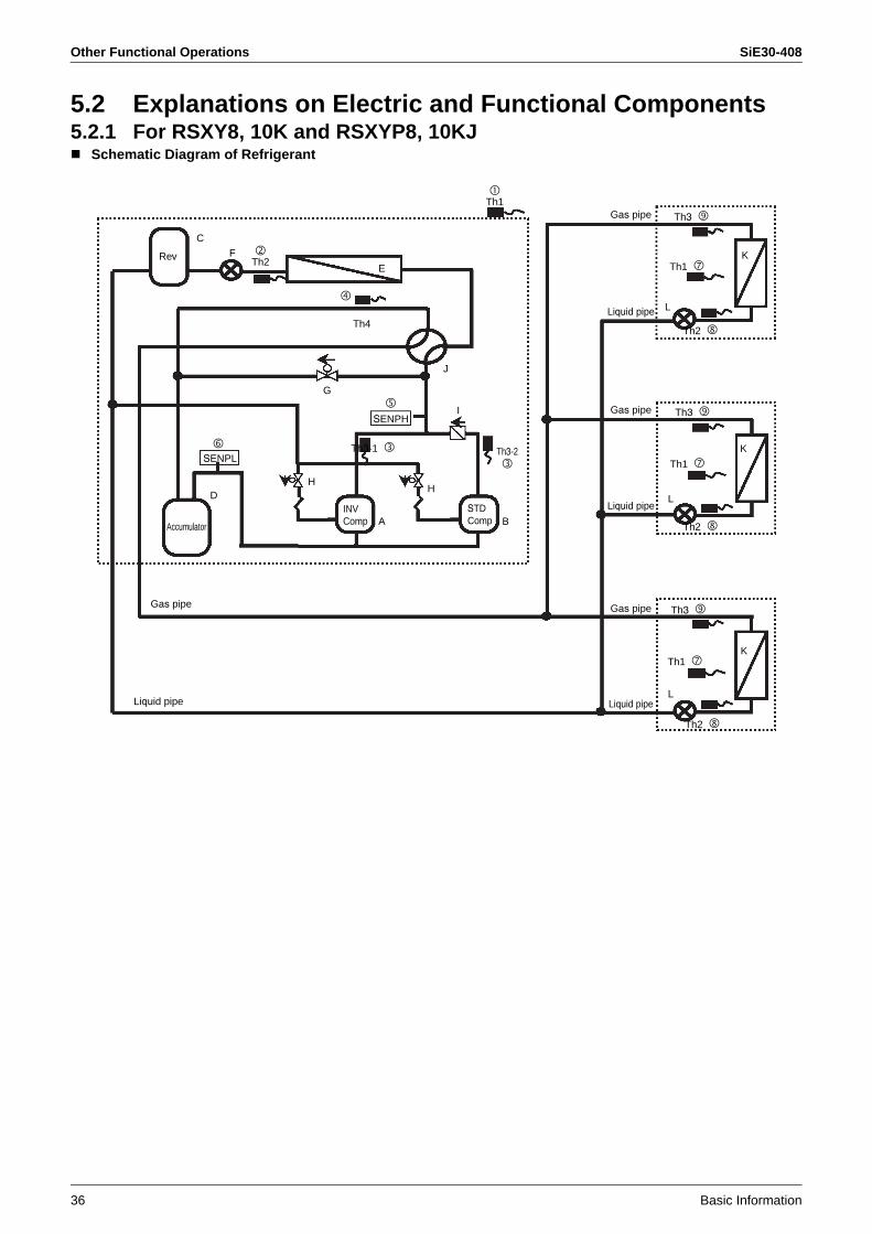
5.2 Explanations on Electric and Functional Components5.2.1 For RSXY8, 10K and RSXYP8, 10KJ
Schematic Diagram of Refrigerant
Rev
C
F
SENPH
SENPL
Th4
Th3-1
Th3
Th1
Th3
Th1
Th2
L
Th2
L
Th3
Th1
Th2
L
K
K
K
J
G
DH
H
A BAccumulator
Gas pipe
Liquid pipe
Liquid pipe
Gas pipe
Gas pipe
Liquid pipe
Gas pipe
Liquid pipe
I
E
Th2
Th3-2
Th1
STDComp
INVComp
SiE30-408 Other Functional Operations
Basic Information 37
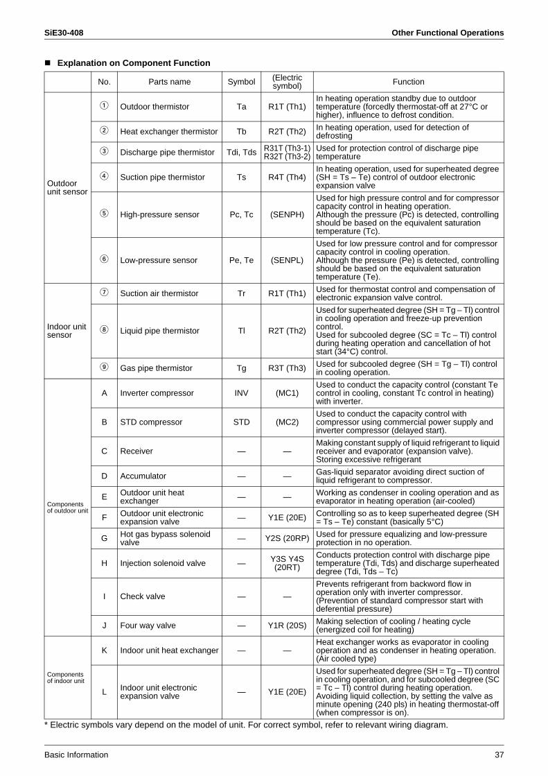
Explanation on Component Function
* Electric symbols vary depend on the model of unit. For correct symbol, refer to relevant wiring diagram.
No. Parts name Symbol (Electricsymbol) Function
Outdoor unit sensor
1 Outdoor thermistor Ta R1T (Th1)In heating operation standby due to outdoor temperature (forcedly thermostat-off at 27°C or higher), influence to defrost condition.
2 Heat exchanger thermistor Tb R2T (Th2) In heating operation, used for detection of defrosting
3 Discharge pipe thermistor Tdi, Tds R31T (Th3-1)R32T (Th3-2)
Used for protection control of discharge pipe temperature
4 Suction pipe thermistor Ts R4T (Th4)In heating operation, used for superheated degree (SH = Ts – Te) control of outdoor electronic expansion valve
5 High-pressure sensor Pc, Tc (SENPH)
Used for high pressure control and for compressor capacity control in heating operation.Although the pressure (Pc) is detected, controlling should be based on the equivalent saturation temperature (Tc).
6 Low-pressure sensor Pe, Te (SENPL)
Used for low pressure control and for compressor capacity control in cooling operation.Although the pressure (Pe) is detected, controlling should be based on the equivalent saturation temperature (Te).
Indoor unit sensor
7 Suction air thermistor Tr R1T (Th1) Used for thermostat control and compensation of electronic expansion valve control.
8 Liquid pipe thermistor Tl R2T (Th2)
Used for superheated degree (SH = Tg – Tl) control in cooling operation and freeze-up prevention control.Used for subcooled degree (SC = Tc – Tl) control during heating operation and cancellation of hot start (34°C) control.
9 Gas pipe thermistor Tg R3T (Th3) Used for subcooled degree (SH = Tg – Tl) control in cooling operation.
Components of outdoor unit
A Inverter compressor INV (MC1)Used to conduct the capacity control (constant Te control in cooling, constant Tc control in heating) with inverter.
B STD compressor STD (MC2)Used to conduct the capacity control with compressor using commercial power supply and inverter compressor (delayed start).
C Receiver — —Making constant supply of liquid refrigerant to liquid receiver and evaporator (expansion valve).Storing excessive refrigerant
D Accumulator — — Gas-liquid separator avoiding direct suction of liquid refrigerant to compressor.
E Outdoor unit heat exchanger — — Working as condenser in cooling operation and as
evaporator in heating operation (air-cooled)
F Outdoor unit electronic expansion valve — Y1E (20E) Controlling so as to keep superheated degree (SH
= Ts – Te) constant (basically 5°C)
G Hot gas bypass solenoid valve — Y2S (20RP) Used for pressure equalizing and low-pressure
protection in no operation.
H Injection solenoid valve — Y3S Y4S (20RT)
Conducts protection control with discharge pipe temperature (Tdi, Tds) and discharge superheated degree (Tdi, Tds – Tc)
I Check valve — —
Prevents refrigerant from backword flow in operation only with inverter compressor.(Prevention of standard compressor start with deferential pressure)
J Four way valve — Y1R (20S) Making selection of cooling / heating cycle (energized coil for heating)
Components of indoor unit
K Indoor unit heat exchanger — —Heat exchanger works as evaporator in cooling operation and as condenser in heating operation. (Air cooled type)
L Indoor unit electronic expansion valve — Y1E (20E)
Used for superheated degree (SH = Tg – Tl) control in cooling operation, and for subcooled degree (SC = Tc – Tl) control during heating operation.Avoiding liquid collection, by setting the valve as minute opening (240 pls) in heating thermostat-off (when compressor is on).

Other Functional Operations SiE30-408
38 Basic Information
5.2.2 For RXY(Q)14, 16MSchematic Diagram of Refrigerant
Filter
Filter
Filter
Fusible plug
Pipe heat exchanger
Check valve
Capillary tube Fan
Check valve
Check valve
Check valve
Check valve
Solenoid valve
Solenoid valve
Filter
FilterFilter
Filter
FilterFilter
Filter
Heat exchanger
Solenoid valve
Capillary tube Capillary tube
Four way valve
Compressor CompressorCompressor
Solenoid valveFilter
Oil separator
Oil separator
J
S
L
D
E
7
2
T
F
N
R
C
V
6
1
U
8
5
H9
O
P
3
4
Q
A B
I
K
G
Pressureregulatingvalve 2
Capillary tube
Electronic expansionvalve
Electronic expansionvalve
Subcooling heatexchanger
Capillary tube
Check valveSolenoidvalve
Check valve
Pressurregulatingvalve 3
Check valve
Check valve
Pressure sensor(High pressure)
High pressureswitch
High pressureswitch
Check valve
Pressureregulatingvalve 1
Check valve
Capillary tube
To oil equalizing pipe of other outdoor unitTo liquid pipe of other outdoor unitTo gas pipe of other outdoor unit
Check valve
Pressure sensor(Low pressure)
R2T R1T
R3T
R2T R1T R1T
R3T
R2T
R3T
Fan Fan Fan
Filter Filter
Electronic expansion valve
Filter Filter
Electronic expansion valve
Filter Filter
Electronic expansion valve
Indoor unit Indoor unit Indoor unit
11 11 11
12
Heat exchanger X Heat exchanger X Heat exchanger X
1212
YYY
Gas pipe
Liquid pipe
Solenoid valveReceiver
High pressureswitch

SiE30-408 Other Functional Operations
Basic Information 39
Functional Parts
No. Part name Symbol (Electricalsymbol) Function
Outdoor unit sensor
1 Outdoor thermistor Ta (R1T) Used to detect outdoor temperature, thus compensating discharge pipe temperature and others.
2 Suction pipe thermistor Ts (R2T)Used to detect suction pipe temperature, thus conducting constant control of the suction superheated degree in heating operation.
3 Discharge pipe thermistor (INV) Tdi (R31T)
Used to detect discharge pipe temperature, thus conducting the protection control of compressor temperature.
4 Discharge pipe thermistor (STD1) Tds1 (R32T)
5 Discharge pipe thermistor (STD2) Tds2 (R33T)
6 Heat exchanger deicer thermistor Tb (R4T)
Used to detect the liquid pipe temperature of air heat exchanger, thus making judgment of defrosting operation.
7Subcooling heat exchanger gas pipe thermistor
Tsh (R5T)
Used to detect gas pipe temperature on the evaporation side of subcooling heat exchanger, thus conducting the constant control of outlet superheated degree of the subcooling heat exchanger.
8 Receiver outlet liquid pipe thermistor Tl (R6T)
Used to detect outlet liquid pipe temperature of the receiver, thus conducting the preventive control of drift between outdoor units in heating operation on the multi outdoor unit system.
9 Oil equalizer pipe thermistor To (R7T)
Used to detect oil equalizer pipe temperature, thus detecting the opening / closing operation of the stop valve for oil equalizer pipe.
N High-pressure thermistor Pc, Tc (S1NPH) Used to detect high pressure.
O Low-pressure thermistor Pe, Te (S1NPL) Used to detect low pressure.
Indoor unit sensor
AT Discharge air thermistor Tr (R1T) Used for thermostat control and the compensation of electronic expansion valve control.
AK Liquid pipe thermistor Tl (R2T)
Used to control superheated degree (SH = Tg – TI) in cooling operation.
• Used to freeze-up prevention control.Used to control subcooled degree (SC = Tc – TI) in heating operation.
• Used for hot start reset (34°C).
AL Gas pipe thermistor Tg (R3T) Used to control superheated degree (SH = Tg – TI) in cooling operation.
Components of outdoor unit
A INV compressor INV (M1C) Inverter compressors are driven by inverter at a frequency in the range of 52 Hz to 210 Hz. STD compressors are only operated with commercial power supply. The following section shows the number of operation steps in combined use of the inverter and STD compressors.RXY(Q)5M : 20 stepsRXY(Q)8, 10, 12M : 29 stepsRXY(Q)14, 16M : 35 steps
B STD compressor 1 STD1 (M2C)
C STD compressor 2 STD2 (M3C)
D INV fan — (M1F)This inverter fan operates at revolution speed in eight steps by inverter drive for heat exchange with the air heat exchanger.
E Electronic expansion valve (Main) EV1 (Y1E)
Used for PI control in heating operation so that the outlet superheated degree of the air heat exchanger will be kept constant.
F Electronic expansion valve (Subcooling) EV2 (Y2E)
Used for PI control so that the outlet superheated degree of the subcooling heat exchanger will be kept constant.
G Solenoid valve (Hot gas) SVP (Y1S) Used to prevent the transitional drop of low pressure.
H Solenoid valve (Oil equalizer) SVO (Y2S) Used to conduct oil equalization between outdoor
units on the outdoor unit multi system.
I Solenoid valve (Receiver gas inlet) SVL (Y3S)
Used to maintain high pressure in cooling operation with low outdoor temperature. Furthermore, used to prevent the refrigerant from accumulating in outdoor units in stop mode on the multi outdoor unit system.
J Solenoid valve (Receiver gas purging) SVG (Y4S) Used to recover the refrigerant into the receiver.

Other Functional Operations SiE30-408
40 Basic Information
KSolenoid valve (Non-operating unit gas discharging)
SVSG (Y5S)On the outdoor unit multi system, used to prevent the refrigerant from accumulating in outdoor units in stop mode.
LSolenoid valve (Non-operating unit liquid pipe closing)
SVSL (Y6S)On the outdoor unit multi system, used to prevent the refrigerant from accumulating in outdoor units in stop mode.
M Four way valve — (Y7S) Used to switch the unit to cooling operation or heating operation.
P High-pressure switch (For INV compressor) — (S1PH)
In order to avoid the increase in high pressure while in malfunction, these switches are actuated at a pressure of 3.8MPa or more to stop the unit.(2.7 MPa for R22 unit)
Components of outdoor unit Q High-pressure switch (For
STD compressor 1) — (S2PH)
R High-pressure switch (For STD compressor 2) — (S3PH)
S Fusible plug — —
In order to avoid increase in pressure at abnormal hating due to fire, the fusible part melts at a temperature of 70 to 75°C, thus relieving pressure into atmosphere.
TPressure regulating valve 1 (Receiver to Discharge pipe)
— —In order to prevent damage to functional parts due to increase in pressure in transport or storage, these valves open at pressure of 2 to 2.7MPa, thus avoiding the increase in pressure.(1.5 ~ 2.0 MPa for R22 unit)
U Pressure regulating valve 2 (Liquid pipe to Receiver) — —
VPressure regulating valve 3 (Oil equalizer pipe to Discharge pipe)
— —
Components of indoor unit
X Indoor unit heat exchanger — —This heat exchanger serves as an evaporator while in cooling operation or a condenser while in heating operation (air cooling).
Y Indoor unit electronic expansion valve — (Y1E)
Used to control the superheated degree (SH = Tg – TI) in cooling operation or subcooled degree (SC = Tc – TI) in heating operation. This valve slightly opens (i.e., 240 pls) with thermostat OFF (compressor ON) in heating operation, thus preventing the accumulation of oil.
No. Part name Symbol (Electricalsymbol) Function

SiE30-408
Field Settings from Remote Controller 41
1. Field Settings from Remote Controller ..................................................421.1 Field Setting Mode .................................................................................431.2 Service Mode .........................................................................................491.3 Check Mode ...........................................................................................541.4 Test Operation Mode..............................................................................55
2. Field Setting on Outdoor Unit ................................................................562.1 Explanation of Basic Mode.....................................................................572.2 Use of Each Setting Mode......................................................................63
Field Settings from Remote Controller SiE30-408
42 Field Settings from Remote Controller
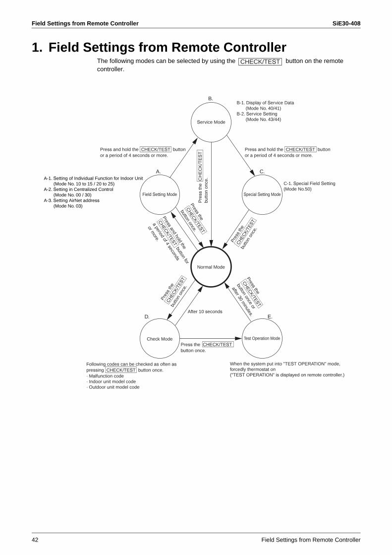
1. Field Settings from Remote ControllerThe following modes can be selected by using the button on the remote controller.
CHECK/TEST
Normal Mode
Check Mode Test Operation Mode
Field Setting Mode Special Setting Mode
Service Mode
After 10 seconds
B.
C.
E.D.
A.A-1. Setting of Individual Function for Indoor Unit (Mode No. 10 to 15 / 20 to 25)A-2. Setting in Centralized Control (Mode No. 00 / 30)A-3. Setting AirNet address (Mode No. 03)
Press and hold the CHECK/TEST buttonor a period of 4 seconds or more.
B-1. Display of Service Data (Mode No. 40/41)B-2. Service Setting (Mode No. 43/44)
Press and hold the CHECK/TEST buttonor a period of 4 seconds or more.
C-1. Special Field Setting(Mode No.50)
Press the CHECK/TESTbutton once.
· Malfunction code· Indoor unit model code· Outdoor unit model code
Following codes can be checked as often aspressing CHECK/TEST button once.
When the system put into "TEST OPERATION" mode, forcedly thermostat on("TEST OPERATION" is displayed on remote controller.)
Pre
ss th
e C
HE
CK
/TE
ST
butto
n on
ce.
Pres
s th
e C
HEC
K/TE
ST
butto
n on
ce.
Press the
CH
ECK/TEST
button once.
Pressand hold the
CH
ECK/TEST
button for
a period of 4 seconds
or more.
Press the
CH
ECK/TEST
button once or
after 30 minutes.
Pres
s th
e C
HEC
K/TE
ST
butto
n on
ce.
SiE30-408 Field Settings from Remote Controller
Field Settings from Remote Controller 43
1.1 Field Setting Mode1.1.1 Settings of Individual Functions for Indoor Unit
Individual functions of indoor unit can be changed from the remote controller. At the time of installation or after service inspection/repair, make field settings in accordance with the following descriptions.Be noted that wrong settings may result in malfunctions.(If any optional accessory is mounted to the indoor unit, changes in settings may be needed. For details, refer to information in the manual for optional accessories.)
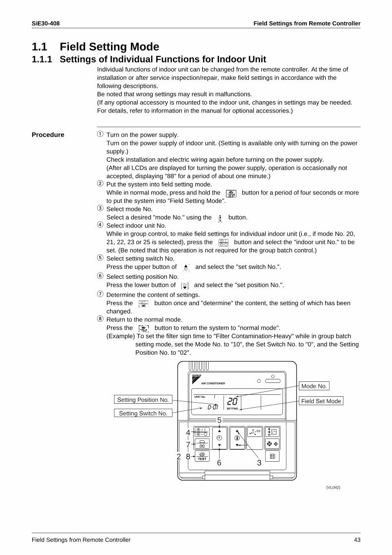
Procedure 1 Turn on the power supply.Turn on the power supply of indoor unit. (Setting is available only with turning on the power supply.)Check installation and electric wiring again before turning on the power supply.(After all LCDs are displayed for turning the power supply, operation is occasionally not accepted, displaying "88" for a period of about one minute.)
2 Put the system into field setting mode.While in normal mode, press and hold the button for a period of four seconds or more to put the system into "Field Setting Mode".
3 Select mode No.Select a desired "mode No." using the button.
4 Select indoor unit No.While in group control, to make field settings for individual indoor unit (i.e., if mode No. 20, 21, 22, 23 or 25 is selected), press the button and select the "indoor unit No." to be set. (Be noted that this operation is not required for the group batch control.)
5 Select setting switch No.Press the upper button of and select the "set switch No.".
6 Select setting position No.Press the lower button of and select the "set position No.".
7 Determine the content of settings.Press the button once and "determine" the content, the setting of which has been changed.
8 Return to the normal mode.Press the button to return the system to "normal mode".(Example) To set the filter sign time to "Filter Contamination-Heavy" while in group batch
setting mode, set the Mode No. to "10", the Set Switch No. to "0", and the Setting Position No. to "02".
0-01
1
AIR CONDITIONER
UNIT No.
TEST
(VL042)
36
Mode No.
Field Set Mode
7
5
82
4
Setting Position No.
Setting Switch No.
20SETTING

Field Settings from Remote Controller SiE30-408
44 Field Settings from Remote Controller
List of Setting Item : Factory setting
Notes: 1. The settings are made by group in a batch. Through the selection of mode No. in the ( ), individual settings can be made by each indoor unit as well. Checking of setting changes, however, can only be enabled in individual mode in the ( ). (In the case of group batch control, even with settings changed, "01" will be displayed at all times.)
2. Make no settings of any item not listed above. Furthermore, if indoor units have no corresponding functions, nothing will be displayed.
3. To return to normal mode, "88" may be displayed to initialize the remote controller.
ModeNo.
Note 1)
Setting Switch
No.Setting Contents
Setting Position No. Note 2)
01 02 03 04
VRVsystem multi indoorunitsettings
10(20)
0
Filter contamination-Heavy/Light(Setting of time intervals to display filter sign)(Use this setting to reduce the time intervals to a half to display filter sign if the filter is easily contaminated.)
Super long life filter
Light
Approx. 10,000 hours
Heavy
Approx. 5000 hours
— —Long life filterApprox. 2500 hours
Approx. 1250 hours
Standard filterApprox. 200 hours
Approx. 100 hours
1Types of long-life filters(Setting of time intervals to display filter sign)
Normal (long life filter)
Super long life filter — —
2 Remote controller thermostat Use Not use — —
3
Computation of interval time to display filter sign(Make this setting not to display the filter sign.)
Display No display — —
12(22)
0Selection of optional accessories output(Field selection of output for adapter for wiring change)
Indoor unit thermostat ON — Operation
outputAbnormal
output
1 External ON-OFF input (Make this setting to conduct ON-OFF operation from outside.) Forcedly OFF ON-OFF
operation
Whenexternal
protectiondevice is
connected
—
2 Thermostat selection (Make this setting to use the remote sensor.) 1°C 0.5°C — —
3Air flow rate with thermostat OFF(Support for increased capacity of air cleaning unit.)
LL Set airflow rate — —
4
Automatic mode differential(Setting of temperature differential for automatic mode on cool/heat simultaneous operation type of unit)
01 : 0 02 : 1 03 : 2 04 : 3 05 : 4 06 : 5 07 : 6 08 : 7
5
Automatic restart function after automatic resetting from power failure(Return to the conditions before power failure)
Not equipped Equipped — —
13(23)
0Adaptable to high ceiling (Make this setting to install unit to ceiling of approx. 2.7 m or more in height.)
StandardN
High ceiling 1H
High ceiling 2S —
1 Selection of airflow direction (Make this setting when blocking pad kit is mounted.)
4 directionsF
3 directionsT
2 directionsW —
3Airflow direction adjustment (Make this setting when outlet decorative plate is mounted.)
Equipped Not equipped — —
4 Setting of air flow direction adjustment range Upward side Standard Downward
side —
5Field selection of air flow rate(Air flow rate control through air outlet for phase control)
Standard Option 1 Option 2 —
15(25)
0 — — — — —
1 Humidification with heating thermostat OFF Not equipped Equipped — —
2Direct duct connection (Make this setting when the unit is connected via ducting directly with outdoor air processing unit.)
Not equipped Equipped — —
3 Interlocking of drain pump and humidifier Not equipped Equipped — —
5Field selection to make individual setting of ventilation under remote and centralized control
Not equipped Equipped — —
6Field selection to make individual setting of cleaning under remote and centralized control
Not equipped Equipped — —

SiE30-408 Field Settings from Remote Controller
Field Settings from Remote Controller 45
1.1.2 Settings of Group No. for Centralized Control SystemIn order to control with central controller or ON/OFF controller, settings of group No. to each group using remote controller are necessary. (Connect remote controller to indoor unit, which does not need remote controller, then remove the remote controller after setting.)
Procedure 1 Turn on the power supply.Turn on the power supply of indoor unit (+ System of rate control). (Setting is available only with turning on the power supply.)Check installation and electric wiring again before turning on the power supply.(After all are displayed for turning the power, operation is occasionally not accepted, displaying "88" for a period of about one minute.)
2 Put the system into setting mode.While in normal mode, press and hold the button for a period of four seconds or more to put the system into "Field Setting Mode".
3 Select mode No.Select mode No. 00 using button.
4 Select group No.Select group No. using the upper and lower button of .(Group No. increases such as 1-00, 1-01 to 1-15, 2-00, to 4-15)
5 Determine group No.Determine the content using button.
6 Return to normal mode.Press button.
Note: Refer to installation manual for using simple remote controller.Refer to each attached instruction manual for the settings of group No. of HRV or various kinds of adapters (general purpose adapters)
Make the settings of group No. while the "group" in LCD is blinking. When no blinking, press the button.
1-00
AIR CONDITIONER
00SETTING
TEST
(VL044)
3
Mode No.
Field Set Mode
5
4
62
Group No.

Field Settings from Remote Controller SiE30-408
46 Field Settings from Remote Controller
Examples of Settings of Group No.
Method for Address Setting for Individual UnitsWhen setting the address in indoor units unit such as adjustment of charges, select mode No. 30. Then, make settings as the following procedure.
Procedure 1 Turn on the power supply.Turn on the power supply of indoor unit (+ Rate control unit). (Setting is available only with turning on the power supply.)Check installation and electric wiring again before turning on the power.(In turning on the power supply after all LCDs are displayed, the operation is occasionally not accepted displaying "88" for a period of about one minute.)
2 Put the system into setting mode.While in normal mode, press and hold the button for a period of four seconds or more to put the system into "Field Setting Mode".
3 Select mode No.Select mode No. 30 using button.
4 Select unit No.Select unit No. using button.
5 Select group No.Select group No. using the upper and lower button of .(Group No. increases such as 1-00, 1-01 to 1-15, 2-00, to 4-15)
6 Determine group No.Determine the content using button.
7 Return to normal mode.Press button.
Note: Refer to installation manual for using simple remote controller.Refer to attached information for the settings of group No. of HRV or various kinds of adapters.
When setting the address in indoor units unit such as adjustment of charges, select mode No. 30. Then make settings as the following procedure.
Indoor unit HRV
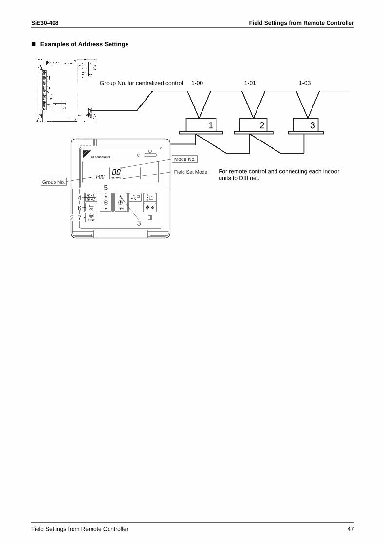
1-00 1-01
1-03 1-04
1-02
Centralized remote controller ON/OFF controller
Group No. for centralized control
No remote controller Group control using remote controller
(automatic address)
Group control using remote controller (automatic address)
SiE30-408 Field Settings from Remote Controller
Field Settings from Remote Controller 47
Examples of Address Settings
Group No. for centralized control 1-00
1 2 3
1-01 1-03
For remote control and connecting each indoor units to DIII net.
001-00 SETTING
AIR CONDITIONER
TEST
3
Mode No.
Field Set Mode
6
5
72
4
Group No.
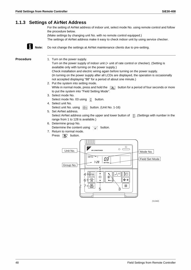
Field Settings from Remote Controller SiE30-408
48 Field Settings from Remote Controller
1.1.3 Settings of AirNet AddressFor the setting of AirNet address of indoor unit, select mode No. using remote control and follow the procedure below.(Make settings by changing unit No. with no remote control equipped.)The settings of AirNet address make it easy to check indoor unit by using service checker.
Note: Do not change the settings at AirNet maintenance clients due to pre-setting.
Procedure 1. Turn on the power supply.Turn on the power supply of indoor unit (+ unit of rate control or checker). (Setting is available only with turning on the power supply.)Check installation and electric wiring again before turning on the power supply.(In turning on the power supply after all LCDs are displayed, the operation is occasionally not accepted displaying "88" for a period of about one minute.)
2. Put the system into setting mode.While in normal mode, press and hold the button for a period of four seconds or more to put the system into "Field Setting Mode".
3. Select mode No.Select mode No. 03 using button.
4. Select unit No.Select unit No. using button. (Unit No. 1-16)
5. Set AirNet address.Select AirNet address using the upper and lower button of . (Settings with number in the range from 1 to 128 is available.)
6. Determine group No.Determine the content using button.
7. Return to normal mode.Press button.
1-28
1
AIR CONDITIONER
UNIT No.
TEST
(VL042)
35
Mode No.
Field Set Mode
6
5
72
4
Group No.
Unit No.
03SETTING

SiE30-408 Field Settings from Remote Controller
Field Settings from Remote Controller 49
1.2 Service ModeThe operation of button of remote controller enables "service data" gain and "service settings" with service mode.
How to Enter the Service Mode
1.2.1 Check on Service Data1 Select mode No.
Select a desired mode No. 40 or 41 using button.2 Select unit No. (For group control only)
Select indoor unit No. to be set using button.3 Select malfunction history No. or sensor data No.
Select a desired malfunction history No. or sensor data No. by using button.4 Each data will be displayed. (Refer to table next page.)5 Return to normal operation mode.
Press button once.
Service modeNormal
operationmode
Field settingmode
2 button for a period of fourseconds or more.
1 button for a period of fourseconds or more.
1-00
1
AIR CONDITIONER
UNIT No.
TEST
(VL042)
1
Mode No.
35
2
Unit No.
40SETTING
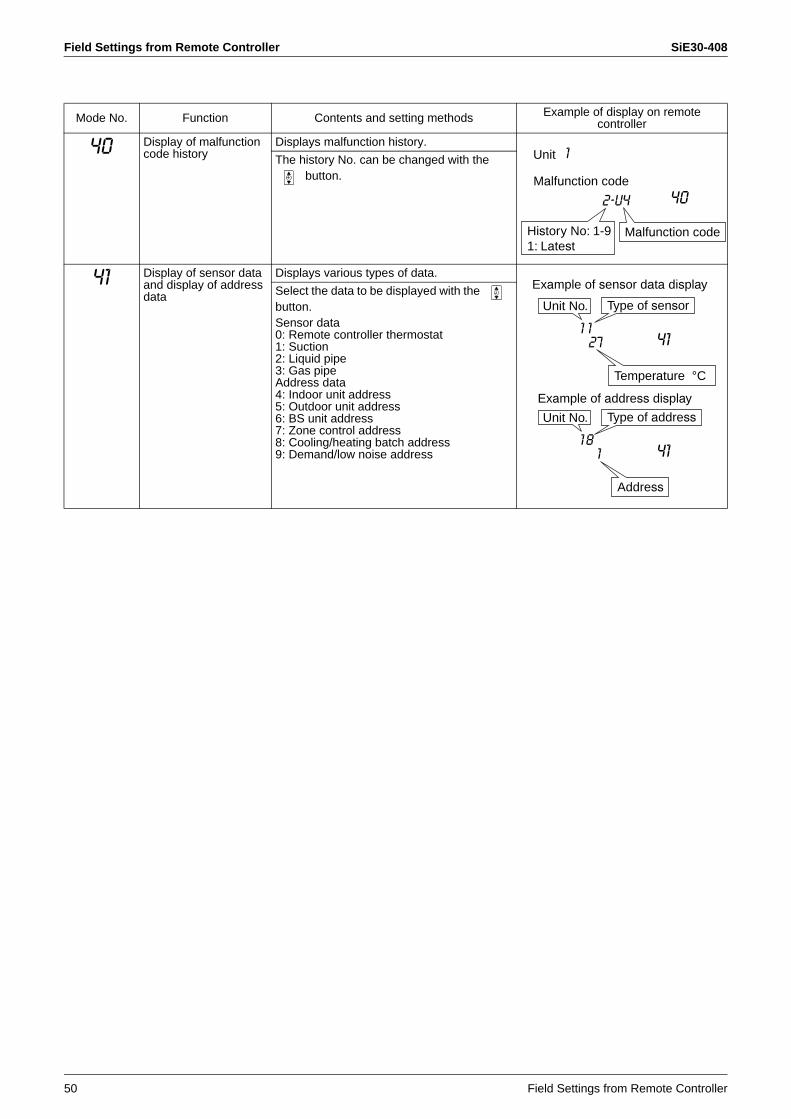
Field Settings from Remote Controller SiE30-408
50 Field Settings from Remote Controller
Mode No. Function Contents and setting methods Example of display on remote controller
40 Display of malfunction code history
Displays malfunction history.
The history No. can be changed with the button.
41 Display of sensor data and display of address data
Displays various types of data.
Select the data to be displayed with the button.Sensor data0: Remote controller thermostat1: Suction2: Liquid pipe3: Gas pipeAddress data4: Indoor unit address5: Outdoor unit address6: BS unit address7: Zone control address8: Cooling/heating batch address9: Demand/low noise address
Unit
Malfunction code
2-U4 40
Malfunction code
1
History No: 1-91: Latest
27 41
Temperature °C
1 1
1 411 8
Address
Example of sensor data display
Unit No. Type of address
Unit No. Type of sensor
Example of address display
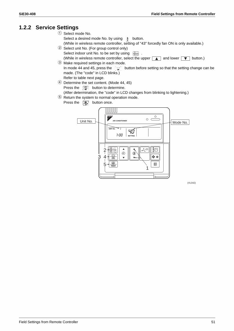
SiE30-408 Field Settings from Remote Controller
Field Settings from Remote Controller 51
1.2.2 Service Settings1 Select mode No.
Select a desired mode No. by using button.(While in wireless remote controller, setting of "43" forcedly fan ON is only available.)
2 Select unit No. (For group control only)Select indoor unit No. to be set by using .(While in wireless remote controller, select the upper and lower button.)
3 Make required settings in each mode.In mode 44 and 45, press the button before setting so that the setting change can be made. (The "code" in LCD blinks.)Refer to table next page.
4 Determine the set content. (Mode 44, 45)Press the button to determine.(After determination, the "code" in LCD changes from blinking to lightening.)
5 Return the system to normal operation mode.Press the button once.
1-00
1
40SETTING
AIR CONDITIONER
UNIT No.
TEST
(VL042)
1
Mode No.
5
243
Unit No.
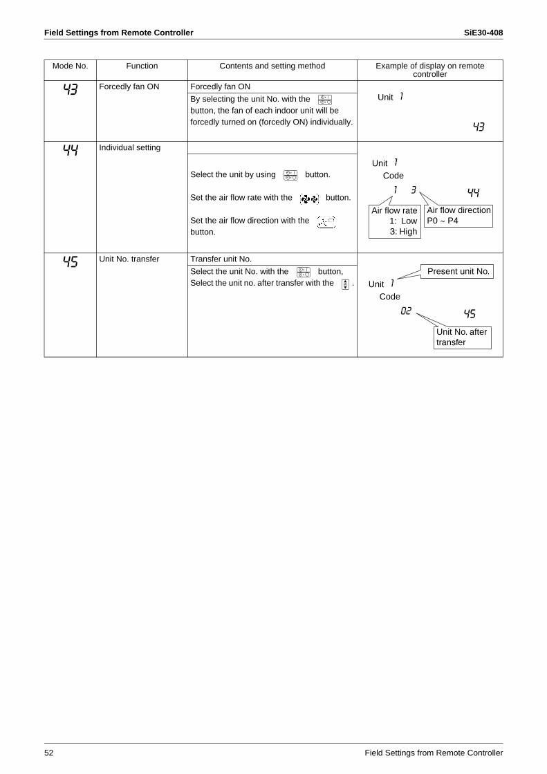
Field Settings from Remote Controller SiE30-408
52 Field Settings from Remote Controller
Mode No. Function Contents and setting method Example of display on remote controller
43 Forcedly fan ON Forcedly fan ON
By selecting the unit No. with the button, the fan of each indoor unit will be forcedly turned on (forcedly ON) individually.
44 Individual setting
Select the unit by using button.
Set the air flow rate with the button.
Set the air flow direction with the button.
45 Unit No. transfer Transfer unit No.
Select the unit No. with the button,Select the unit no. after transfer with the .
Unit
43
1
Unit
44
1
1 3
Code
Air flow direction P0 ~ P4
Air flow rate1: Low3: High
Unit
45
1
02
Code
Present unit No.
Unit No. aftertransfer

SiE30-408 Field Settings from Remote Controller
Field Settings from Remote Controller 53
Method to Specify the Indoor Unit No.In indoor units where group control is made, mode No. 43 (turn on the forcedly fan) is used to specify the location of installation of the indoor unit with a certain No.(When the malfunction occurs within remote control group, above method can also be utilized to specify the indoor unit which has the trouble.)
Procedure Turn on the power supply.1 Turn on the power supply of indoor unit (+ rate control unit).
(No settings can be made without turning on the power supply.)Check the installation and electric wirings once again before turning on the power supply.(When the power supply is turned on, there may be cases where any operation cannot be accepted with "88" displayed once.)
2 Put the system into setting modePress the button for a period of 4 seconds or more, and put the system into "Field Setting Mode".
3 Put the system into service mode.Press the button for a period of 4 seconds or more once again.
4 Select the mode No.Select the mode No. 43 using the button. (Unit No. 1-16)
5 Select the unit No.Select the unit No. using the button. (Unit No. 1-16)
6 The fan in relevant indoor units starts to operate.7 Turn the system into the normal mode.
Press the button.
1-00
1
43SETTING
AIR CONDITIONER
UNIT No.
TEST
(VL042)
4
Mode No.
732
5
Unit No.
Field Set Mode
Group No.
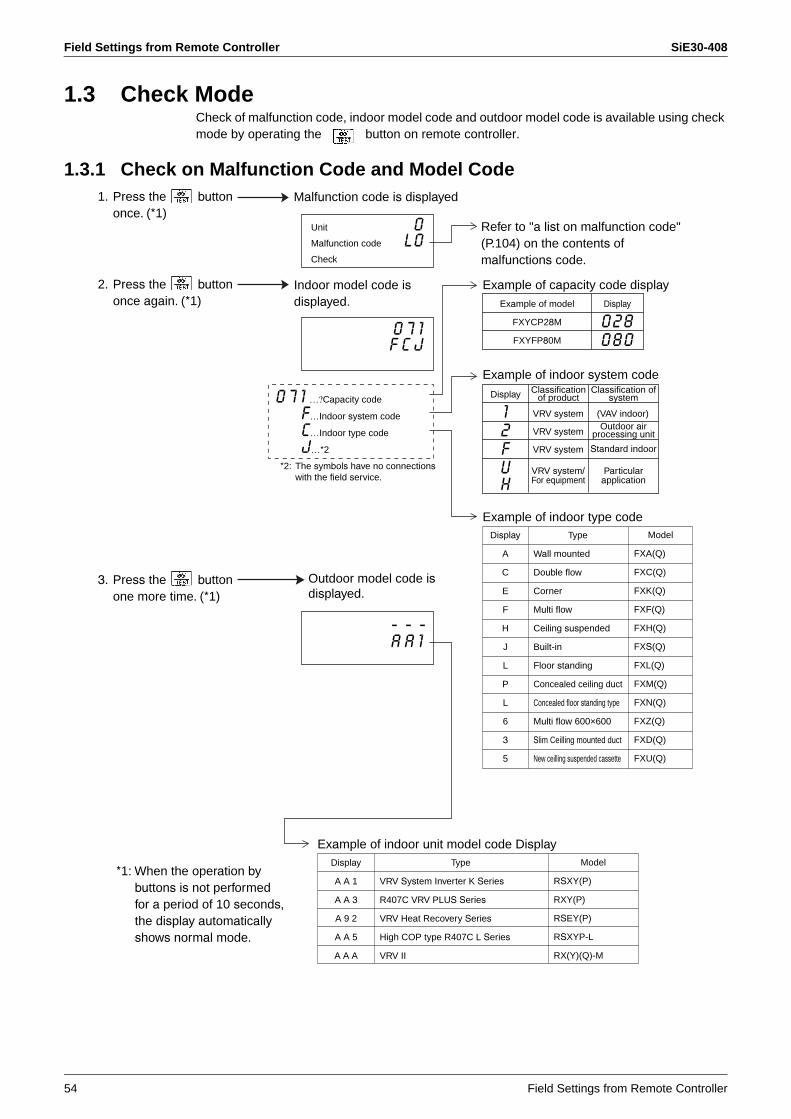
Field Settings from Remote Controller SiE30-408
54 Field Settings from Remote Controller
1.3 Check ModeCheck of malfunction code, indoor model code and outdoor model code is available using check mode by operating the button on remote controller.
1.3.1 Check on Malfunction Code and Model Code
*1: When the operation bybuttons is not performed for a period of 10 seconds,the display automaticallyshows normal mode.
Example of model
FXYCP28M
FXYFP80M
Example of capacity code display
Classificationof product
VRV system
VRV system
VRV system
VRV system/For equipment
Classification of system
(VAV indoor)Outdoor air
processing unit
Standard indoor
Particularapplication
Example of indoor system code
Example of indoor type code
Example of indoor unit model code Display
Malfunction code is displayed
Display
0 2 80 8 0
Display
12FUH
2. Press the buttononce again. (*1)
1. Press the buttononce. (*1)
3. Press the buttonone more time. (*1)
Unit 0Malfunction code L 0Check
Indoor model code isdisplayed.
0 7 1F C J
0 7 1 …?Capacity code
F…Indoor system code
C…Indoor type code
J…*2
*2: The symbols have no connectionswith the field service.
Outdoor model code isdisplayed.
- - -A A 1
Refer to "a list on malfunction code" (P.104) on the contents of malfunctions code.
Type
Wall mounted
Double flow
Corner
Multi flow
Ceiling suspended
Built-in
Floor standing
Concealed ceiling duct
Concealed floor standing type
Multi flow 600×600
Slim Ceilling mounted duct
New ceilling suspended cassette
Display
A
C
E
F
H
J
L
P
L
6
3
5
Model
FXA(Q)
FXC(Q)
FXK(Q)
FXF(Q)
FXH(Q)
FXS(Q)
FXL(Q)
FXM(Q)
FXN(Q)
FXZ(Q)
FXD(Q)
FXU(Q)
Type
VRV System Inverter K Series
R407C VRV PLUS Series
VRV Heat Recovery Series
High COP type R407C L Series
VRV II
Display
A A 1
A A 3
A 9 2
A A 5
A A A
Model
RSXY(P)
RXY(P)
RSEY(P)
RSXYP-L
RX(Y)(Q)-M
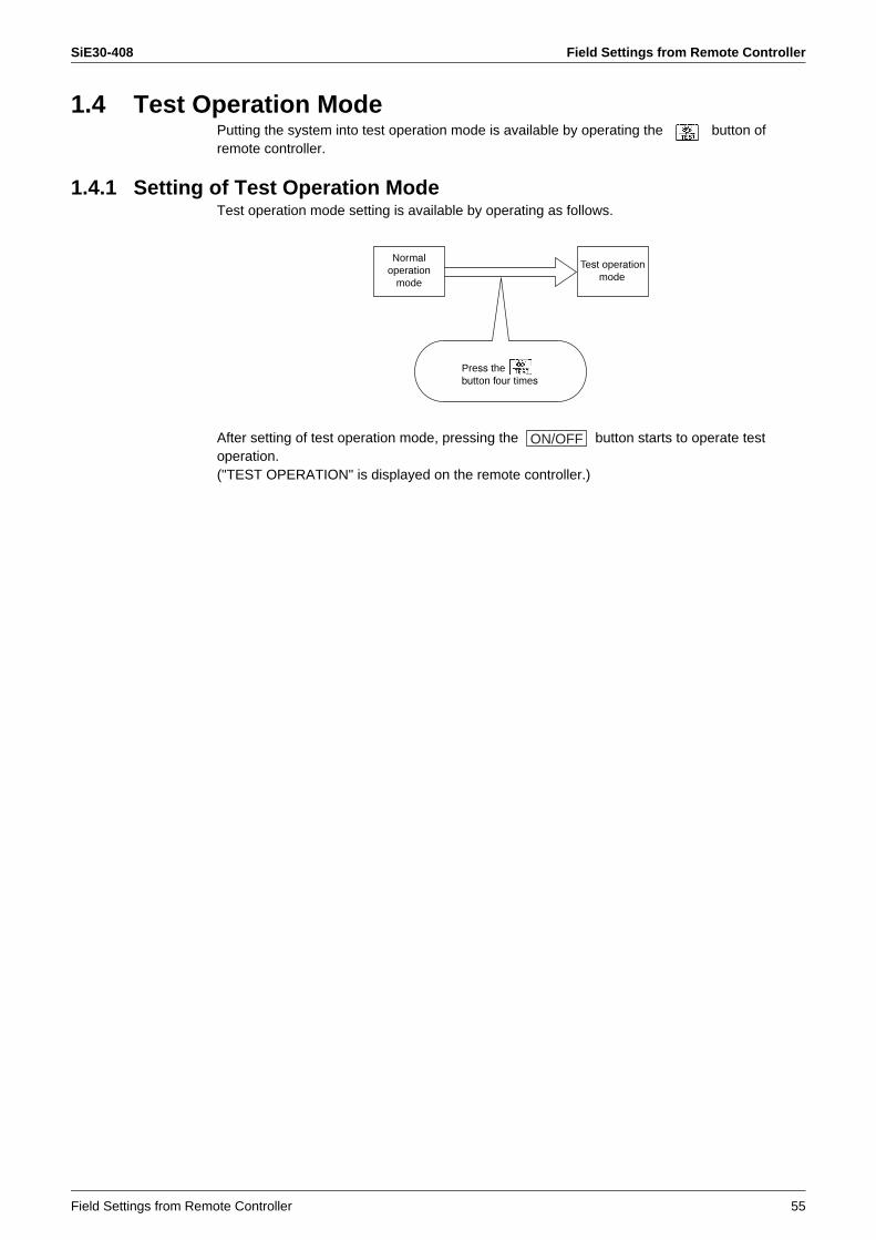
SiE30-408 Field Settings from Remote Controller
Field Settings from Remote Controller 55
1.4 Test Operation ModePutting the system into test operation mode is available by operating the button of remote controller.
1.4.1 Setting of Test Operation ModeTest operation mode setting is available by operating as follows.
After setting of test operation mode, pressing the button starts to operate test operation.("TEST OPERATION" is displayed on the remote controller.)
Normaloperation
mode
Test operationmode
Press thebutton four times
ON/OFF

Field Setting on Outdoor Unit SiE30-408
56 Field Settings from Remote Controller
2. Field Setting on Outdoor UnitUsing pushbutton switches on the PC board enables a variety of settings.However, setting items and setting No. etc. are different according to the model.The following explanation was made based on the representative models of RX(Y)(Q) ~ M. For further details, refer to each service manual of applicable model of the target machine.
* For the multi-outdoor system, make setting using the master unit. (Setting using the slave unit is not valid.)
The following 3 setting modes are available.1. Setting mode 1 (H1P: OFF)
Initial state (while in normal operation): Used to make setting of the method of "Cool/Heat selection".This mode is displayed while in "malfunction", "low noise control", and "demand control" as well.
2. Setting mode 2 (H1P: ON)This mode is used to make changes of operating conditions or settings of a variety of addresses, mainly for service work.
3. Monitor mode (H1P: Blinking)This mode is used to check the contents set in Setting mode 2.
Procedure for Changing Mode
Steps to Change Mode
BS1
MODE
BS2
SET
BS3
RETURN
BS4
TEST
BS5
RESET
(V2760)
Setting mode 1 Monitor mode
H1P
Blinking
MODE MODE
Off
H1P
Setting mode 2
MODE
On
H1P
Push and hold the BS1(MODE button) for 5 seconds.
Push the BS1(MODE button) one time.
(Normal)
(V2761)
Push the BS1(MODE button)one time.
Using the MODE button, the modes can be changed as follows.
Check item selection (Set)
Contents display
Monitor mode
Setting item selection (Set)
Setting mode 2
(Set): Select mode with BS2 (SET button) in each selection step.
Press BS1(MODE button).Press BS1 (MODE button) for more than 5 sec.
(V2762)
Setting mode 1(Initial condition)
Press BS3(RETURN button).
Press BS3(RETURN button).
Press BS3(RETURN button).
Setting condition selection (Set)
Setting condition (Contents) display
Press BS1(MODE button).
Press BS3(RETURN button).
Press BS3(RETURN button).
Press BS1(MODE button).
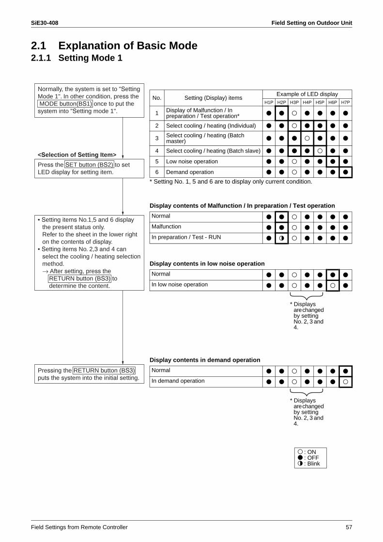
SiE30-408 Field Setting on Outdoor Unit
Field Settings from Remote Controller 57
2.1 Explanation of Basic Mode2.1.1 Setting Mode 1
* Setting No. 1, 5 and 6 are to display only current condition.
Display contents of Malfunction / In preparation / Test operation
Display contents in low noise operation
Display contents in demand operation
Normally, the system is set to "SettingMode 1". In other condition, press the MODE button(BS1) once to put the system into "Setting mode 1".
<Selection of Setting Item>
Press the SET button (BS2) to setLED display for setting item.
• Setting items No.1,5 and 6 displaythe present status only.Refer to the sheet in the lower right on the contents of display.
• Setting items No. 2,3 and 4 canselect the cooling / heating selectionmethod.→ After setting, press the RETURN button (BS3) to determine the content.
Pressing the RETURN button (BS3)puts the system into the initial setting.
No. Setting (Display) itemsExample of LED display
H1P H2P H3P H4P H5P H6P H7P
1 Display of Malfunction / In preparation / Test operation* 7 7 8 7 7 7 7
2 Select cooling / heating (Individual) 7 7 8 7 7 7 7
3 Select cooling / heating (Batch master) 7 7 7 8 7 7 7
4 Select cooling / heating (Batch slave) 7 7 7 7 8 7 7
5 Low noise operation 7 7 8 7 7 7 7
6 Demand operation 7 7 8 7 7 7 7
Normal 7 7 8 7 7 7 7
Malfunction 7 7 8 7 7 7 7
In preparation / Test - RUN 7 9 8 7 7 7 7
Normal 7 7 8 7 7 7 7
In low noise operation 7 7 8 7 7 8 7
* Displays are changed by setting No. 2, 3 and 4.
Normal 7 7 8 7 7 7 7
In demand operation 7 7 8 7 7 7 8
* Displays are changed by setting No. 2, 3 and 4.
8: ON7: OFF9: Blink

Field Setting on Outdoor Unit SiE30-408
58 Field Settings from Remote Controller
2.1.2 Setting Mode 2
↑The numbers in the "No." column show the number of times to press the
.
No. Setting item Set Content
0Emergency operation (INV compressor operation inhibit)
In defect of the INV compressor, operation is made only using the STD compressor. The operation is for temporary use until replacing of the compressor. The comfort declines excessively. Therefore, replace the compressor without delay.(However, for RX(Y)(Q)5M, this setting is not available.)
1 Address in batch cooling/heating Sets the address in unified cooling/heating operation.
2 Low noise · Demand address Address in low noise and demand operation
5 Indoor unit forcedly fan H The indoor fan in the stop condition is forcedly to operate. (H tap)
6 Indoor unit forcedly operation Indoor unit is forcedly to operate.
8 Te setting Target evaporation temperature in cooling
9 Tc setting Target condensing temperature in heating
10 Setting of defrost selection
Changes temperature conditions for defrosting. Setting is available to defrost quick or slow.
11 Starting in sequence setting
Sets when starting in sequence.(ON is factory setting.)
12 External low noise · Demand setting Receives the low noise or the demand signal from outside.
13 AirNet address Sets the AirNet address.
18 High static pressure setting
Set when mounting air discharge duct and operating in high static pressure
19Emergency operation (STD compressor operation inhibit)
In defect of the STD compressor, operation is made only using the INV compressor. The operation is for temporary use until replacing of the compressor. The comfort declines excessively. Therefore, replace the compressor without delay.(However, for RX(Y)(Q)5M, this setting is not available.)
20 Setting of refrigerant re-filling operation Makes refrigerant re-filling operation.
21Setting of refrigerant recovery vacuuming mode
Sets to refrigerant collection mode.
22 Setting of nighttime low noise level
Enables to set the simplified operation of automatic night low noise.Time is subject to "starting set" and "ending set".
25 Setting of external low noise level
Sets the low noise level when the low noise signal is input from outside.
26 Starting time of nighttime low noise operation
Sets the starting time of the nighttime low noise.("Setting of the nighttime low noise" is required.)
27 Closing time of the night low noise operation
Sets the closing time of the nighttime low noise.("Setting of the nighttime low noise" is required.)
28 Setting of power transistor checks mode
Uses for the troubleshooting of the DC compressor. The inverter waveform is output without wiring to the compressor. Therefore, the mode is convenient to identify if the defect part is the compressor or the PC board.
29 Setting of capacity priority
When the low noise operation or the nighttime low noise operation was performed, this setting enables to release the low noise operation automatically if the capacity is required.
30 Setting of demand 1 level Change the target value of power consumption when the demand 1 is input.
32 Setting of constant demand
The demand 1 is always performed by making this setting without input from outside.(It is effective against such a problem that the capacity in the breaker is small and the breaker trips when the load is growing.)
38Emergency operation (Master unit with multi-outdoor-unit system is inhibited to operate.)
Prohibits operating the corresponding outdoor unit tentatively for the parts of outdoor-multi malfunction. The comfort declines excessively. Therefore, replace the parts without delay.
39Emergency operation (Slave unit 1 with multi-outdoor-unit system is inhibited to operate.)
40Emergency operation (Slave unit 2 with multi-outdoor-unit system is inhibited to operate.)
Press and hold the MODE button(BS1) for a period of five seconds or more to put the system into "Settingmode 2".
<Selection of Setting Items>
Press the SET button (BS2) and setthe LED display to setting itemsshown on the right.
Press the RETURN button (BS3) to finalize the setting items. (The currentsetting conditions are displayed while blinking.)
<Selection of setting conditions>
Press the SET button (BS2) and setthe LED display to conditions to beset.
Press the RETURN button (BS3) to finalize the check items.
Press the RETURN button (BS3) andput the system into the initial state of "Setting mode 2".
* If you become confused about the setting halfway through it, press the MODE button (BS1) . Thus, the system will return to Setting mode 1.
SET button (BS2)

SiE30-408 Field Setting on Outdoor Unit
Field Settings from Remote Controller 59
No. Used Example
LED Display
Setting condition display
*Factory setting
Page
H1P
Under prepa-ration, MalfunctionH2P
Cooling/Heating selection
Lownoise
H6P
Demand
H7P
Indivi-dualH3P
Batch master
H4P
Batch slaveH5P
0
For emergency measures by inverter in individual installation machine.The unit will stop when this setting made with multi system unit.
8 7 7 7 7 7 7Normal operationEmergency operation (INV compressor is inhibited to operate.)
8777778*8777787
1 8 7 7 7 7 7 8Address 0Binary number 1(6 digits)
31
8777777*8777778
~8788888
2 Setting for mounting of external control adapter 8 7 7 7 7 8 7
Address 0Binary number 1(6 digits)
31
8777777*8777778
~8788888
5Used for deciding the system either indoor or outdoor.
8 7 7 7 8 7 8 Normal operationIndoor forcedly fan H
8777778*8777787
6
Forcedly puts the indoor unit into the test operation mode.[UNDER CENTRALIZED CONTROL] is displayed in indoor remote controller.
8 7 7 7 8 8 7 Normal operationIndoor forcedly operation
8777778*8777787
8
Correction of the pressure loss in pipingSelect according to the piping length and scale of the pressure loss.
8 7 7 8 7 7 7HighNormalLow
87778778777787*8777778
9
Correction of the pressure loss in pipingSelect according to the piping length and scale of the pressure loss.
8 7 7 8 7 7 8HighNormalLow
87778778777787*8777778
10 Changing of the time for entering in defrost. 8 7 7 8 7 8 7
QuickNormalSlow
87778778777787*8777778
11 8 7 7 8 7 8 8 EquippedNot equipped
8777778*8777787
12
Setting when mounting of external control adapter.Can be used together with No. 30.
8 7 7 8 8 7 7External low noise · Demand: NoExternal low noise · Demand: YES
8777778*
8777787
13 Convenient to check the checker type 3 system 8 7 7 8 8 7 8
Address 0Binary number 1(6 digits)
63
8777777*8777778
~8788888
18 8 7 8 7 7 8 7High static pressure setting OFFHigh static pressure setting ON
8777778*
8777787
19
For emergency measures of individual installation unit when the defect of STD.
8 7 8 7 7 8 8
OFFSTD 1, 2 operation: InhibitedSTD 2 operation: Inhibited
8777777*8777778
8777787
20 Setting for refrigerant charging 8 7 8 7 8 7 7
Refrigerant charging: OFFRefrigerant charging: ON
8777778*
8777787
21Fully opens motorized valve forcedly in indoor or outdoor unit
8 7 8 7 8 7 8Refrigerant recovery: OFFRefrigerant recovery: ON
8777778*
8777787
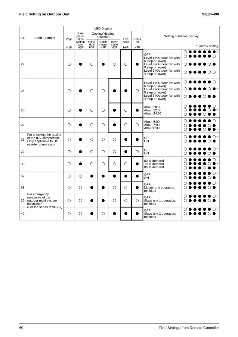
Field Setting on Outdoor Unit SiE30-408
60 Field Settings from Remote Controller
22 8 7 8 7 8 8 7
OFFLevel 1 (Outdoor fan with 6 step or lower)Level 2 (Outdoor fan with 5 step or lower)Level 3 (Outdoor fan with 4 step or lower)
8777777*8777778
8777787
8777788
25 8 7 8 8 7 7 8
Level 1 (Outdoor fan with 6 step or lower)Level 2 (Outdoor fan with 5 step or lower)Level 3 (Outdoor fan with 4 step or lower)
8777778
8777787*
8777877
26 8 7 8 8 7 8 7About 20:00About 22:00About 24:00
87777788777787*8777877
27 8 7 8 8 7 8 8About 6:00About 7:00About 8:00
877777887777878777877*
28
For checking the quality of the INV compressor.Only applicable to DC inverter compressor.
8 7 8 8 8 7 7 OFFON
8777778*8777787
29 8 7 8 8 8 7 8 OFFON
8777778*8777787
30 8 7 8 8 8 8 760 % demand70 % demand80 % demand
87777788777787*8777877
32 8 8 7 7 7 7 7 OFFON
8777778*8777787
38
For emergency measures of the outdoor-multi system installation(For the series of VRV II)
8 8 7 7 8 8 7OFFMaster unit operation: Inhibited
8777778*8777787
39 8 8 7 7 8 8 8OFFSlave unit 1 operation: Inhibited
8777778*8777787
40 8 8 7 8 7 7 7OFFSlave unit 2 operation: Inhibited
8777778*8777787
No. Used Example
LED Display
Setting condition display
*Factory setting
Page
H1P
Under prepa-ration, MalfunctionH2P
Cooling/Heating selection
Lownoise
H6P
Demand
H7P
Indivi-dualH3P
Batch master
H4P
Batch slaveH5P

SiE30-408 Field Setting on Outdoor Unit
Field Settings from Remote Controller 61
2.1.3 Monitor Mode
↑The numbers in the "No." column show the number of times to press the
.
Display contents of setting item No.0 “Various settings”
Explanation of Used Examples* 1: Use when checking the checker system.* 2: Check the numbers to connected indoor units for transmission
malfunction, etc.* 3: Check the malfunction code.* 4: Check the Retry contents.* 5: Check when the operation pattern of outdoor unit is unusual.
No. Setting itemsLED display Data
displayH1P H2P H3P H4P H5P H6P H7P
0 Various settings 9 7 7 7 7 7 7 Refer to below
1 Address in batch cooling / heating 9 7 7 7 7 7 8
Lower six digits
2 Low noise · Demand address 9 7 7 7 7 8 7
4 AirNet address (*1) 9 7 7 7 8 7 7
5 The number of connected indoor units (*2) 9 7 7 7 8 7 8
7 The number of connected zone units (Outdoor, except BS) 9 7 7 7 8 8 8
8 The number of outdoor units 9 7 7 8 7 7 7
11 The number of zone units (Outdoor, except BS) 9 7 7 8 7 8 8 Lower six
digits
12 The number of terminals 9 7 7 8 8 7 7Lowerfourdigits(upper)
13 The number of terminals 9 7 7 8 8 7 8Lowerfourdigits(lower)
14 Content of malfunction (latest)
(*3)
8 7 7 8 8 8 7Refer to page104,Malfunc-tion code list in the chapter oftrouble-shooting.
15 Content of malfunction (one cycle before) 8 7 7 8 8 8 8
16 Content of malfunction (two cycles before) 8 7 8 7 7 7 7
20 Content of retry (latest)
(*4)
8 7 8 7 8 7 7
21 Content of retry (one cycle before) 8 7 8 7 8 7 8
22 Content of retry (two cycles before) 8 7 8 7 8 8 7
Pressing the MODE button (BS1)while in "Setting mode 1" will enter "Monitor mode".
<Selection of Setting Item>
Press the SET button (BS2) and setthe LED display to setting items.
<Check the set contents>
Pressing the RETURN button (BS3)will display respective data by LED.
Pressing the RETURN button (BS3)will put the system into the initial stateof "Monitor mode".
* Pressing the MODE button (BS1) will return the system to "Setting mode 1".
SET button (BS2)
Setting of EMG operation/ backup operation (*5)
ON 9 7 7 8 7 7 7
OFF 9 7 7 7 7 7 7
Setting of defrost selection
Shorttime 9 7 7 7 8 7 7
Middle time 9 7 7 7 9 7 7
Long time 9 7 7 7 7 7 7
Te setting
H 9 7 7 7 7 8 7M 9 7 7 7 7 9 7L 9 7 7 7 7 7 7
Tc setting
H 9 7 7 7 7 7 8M 9 7 7 7 7 7 9L 9 7 7 7 7 7 7
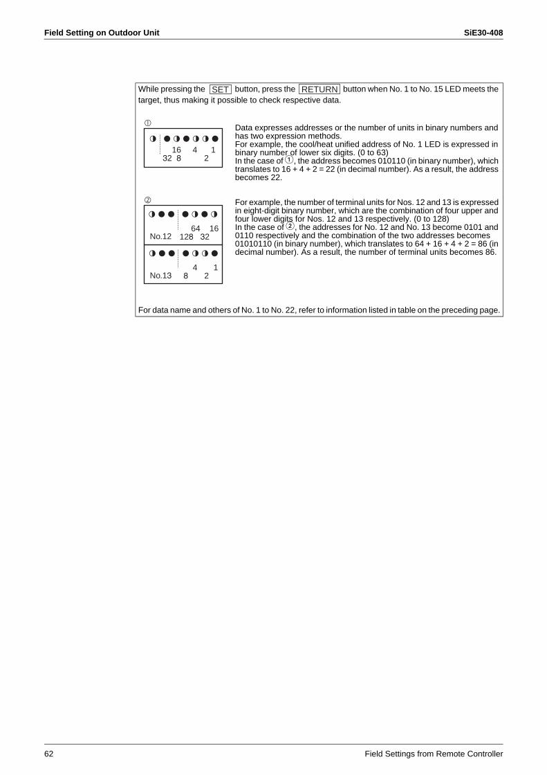
Field Setting on Outdoor Unit SiE30-408
62 Field Settings from Remote Controller
While pressing the button, press the button when No. 1 to No. 15 LED meets the target, thus making it possible to check respective data.
Data expresses addresses or the number of units in binary numbers and has two expression methods.For example, the cool/heat unified address of No. 1 LED is expressed in binary number of lower six digits. (0 to 63)In the case of 1, the address becomes 010110 (in binary number), which translates to 16 + 4 + 2 = 22 (in decimal number). As a result, the address becomes 22.
For example, the number of terminal units for Nos. 12 and 13 is expressed in eight-digit binary number, which are the combination of four upper and four lower digits for Nos. 12 and 13 respectively. (0 to 128)In the case of 2, the addresses for No. 12 and No. 13 become 0101 and 0110 respectively and the combination of the two addresses becomes 01010110 (in binary number), which translates to 64 + 16 + 4 + 2 = 86 (in decimal number). As a result, the number of terminal units becomes 86.
For data name and others of No. 1 to No. 22, refer to information listed in table on the preceding page.
SET RETURN
9 797997
16 4 132 8 2
977 7979
No.12
977 7997
4 1No.13 8 2
64 16128 32
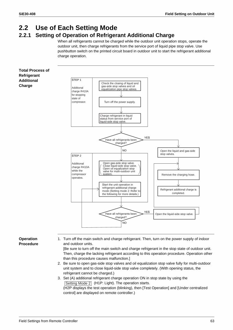
SiE30-408 Field Setting on Outdoor Unit
Field Settings from Remote Controller 63
2.2 Use of Each Setting Mode2.2.1 Setting of Operation of Refrigerant Additional Charge
When all refrigerants cannot be charged while the outdoor unit operation stops, operate the outdoor unit, then charge refrigerants from the service port of liquid pipe stop valve. Use pushbutton switch on the printed circuit board in outdoor unit to start the refrigerant additional charge operation.
Total Process of RefrigerantAdditionalCharge
Operation Procedure
1. Turn off the main switch and charge refrigerant. Then, turn on the power supply of indoor and outdoor units.[Be sure to turn off the main switch and charge refrigerant in the stop state of outdoor unit. Then, charge the lacking refrigerant according to this operation procedure. Operation other than this procedure causes malfunction.]
2. Be sure to open gas-side stop valves and oil equalization stop valve fully for multi-outdoor unit system and to close liquid-side stop valve completely. (With opening status, the refrigerant cannot be charged.)
3. Set (A) additional refrigerant charge operation ON in stop state by using the (H1P: Light). The operation starts.
(H2P displays the test operation (blinking), then [Test Operation] and [Under centralized control] are displayed on remote controller.)
Have all refrigerants beencharged?
Have all refrigerants beencharged?
YES
NO
YES
NO
Open the liquid and gas-sidestop valves.
Open the liquid-side stop valve.
Remove the charging hose.
Refrigerant additional charge iscompleted.
Start the unit operation in refrigerant additional chargemode (Setting mode 2: Refer to the following for more details.)
STEP 1
Additionalcharge R410A for stoppingstate of compressor.
STEP 2
Additionalcharge R410A while the compressoroperates.
Check the closing of liquid andgas-side stop valves and oil equalization pipe stop valves.
Open gas-side stop valve. Close liquid-side stop valve. Open oil equalization stopvalve for multi-outdoor unitsystem.
Turn off the power supply.
Charge refrigerant in liquidstatus from service port of liquid-side stop valve.
Setting Mode 2
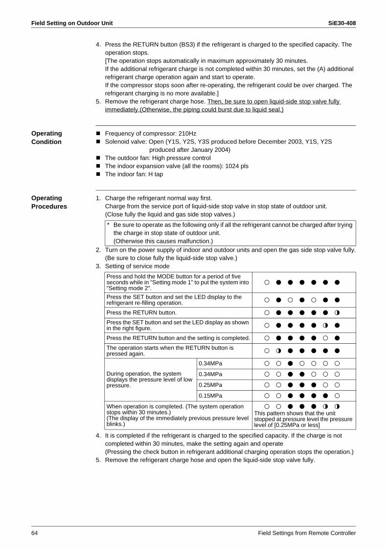
Field Setting on Outdoor Unit SiE30-408
64 Field Settings from Remote Controller
4. Press the RETURN button (BS3) if the refrigerant is charged to the specified capacity. The operation stops.[The operation stops automatically in maximum approximately 30 minutes.If the additional refrigerant charge is not completed within 30 minutes, set the (A) additional refrigerant charge operation again and start to operate.If the compressor stops soon after re-operating, the refrigerant could be over charged. The refrigerant charging is no more available.]
5. Remove the refrigerant charge hose. Then, be sure to open liquid-side stop valve fully immediately.(Otherwise, the piping could burst due to liquid seal.)
Operating Condition
Frequency of compressor: 210HzSolenoid valve: Open (Y1S, Y2S, Y3S produced before December 2003, Y1S, Y2S
produced after January 2004)The outdoor fan: High pressure controlThe indoor expansion valve (all the rooms): 1024 plsThe indoor fan: H tap
Operating Procedures
1. Charge the refrigerant normal way first.Charge from the service port of liquid-side stop valve in stop state of outdoor unit.(Close fully the liquid and gas side stop valves.)
2. Turn on the power supply of indoor and outdoor units and open the gas side stop valve fully.(Be sure to close fully the liquid-side stop valve.)
3. Setting of service mode
4. It is completed if the refrigerant is charged to the specified capacity. If the charge is not completed within 30 minutes, make the setting again and operate(Pressing the check button in refrigerant additional charging operation stops the operation.)
5. Remove the refrigerant charge hose and open the liquid-side stop valve fully.
* Be sure to operate as the following only if all the refrigerant cannot be charged after trying the charge in stop state of outdoor unit.(Otherwise this causes malfunction.)
Press and hold the MODE button for a period of five seconds while in "Setting mode 1" to put the system into "Setting mode 2".
8 7 7 7 7 7 7
Press the SET button and set the LED display to the refrigerant re-filling operation. 8 7 8 7 8 7 7
Press the RETURN button. 8 7 7 7 7 7 9
Press the SET button and set the LED display as shown in the right figure. 8 7 7 7 7 9 7
Press the RETURN button and the setting is completed. 8 7 7 7 7 8 7
The operation starts when the RETURN button is pressed again. 8 9 7 7 7 7 7
During operation, the system displays the pressure level of low pressure.
0.34MPa 8 8 7 8 8 8 8
0.34MPa 8 8 7 7 8 8 8
0.25MPa 8 8 7 7 7 8 8
0.15MPa 8 8 7 7 7 7 8
When operation is completed. (The system operation stops within 30 minutes.)(The display of the immediately previous pressure level blinks.)
8 8 7 7 7 9 9This pattern shows that the unit stopped at pressure level the pressure level of [0.25MPa or less]
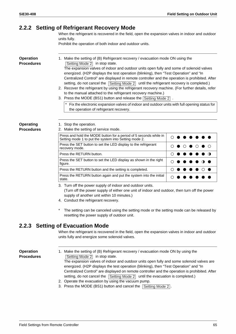
SiE30-408 Field Setting on Outdoor Unit
Field Settings from Remote Controller 65
2.2.2 Setting of Refrigerant Recovery ModeWhen the refrigerant is recovered in the field, open the expansion valves in indoor and outdoor units fully.Prohibit the operation of both indoor and outdoor units.
Operation Procedures
1. Make the setting of (B) Refrigerant recovery / evacuation mode ON using the in stop state.
The expansion valves of indoor and outdoor units open fully and some of solenoid valves energized. (H2P displays the test operation (blinking), then “Test Operation” and “In Centralized Control” are displayed in remote controller and the operation is prohibited. After setting, do not cancel the until the refrigerant recovery is completed.)
2. Recover the refrigerant by using the refrigerant recovery machine. (For further details, refer to the manual attached to the refrigerant recovery machine.)
3. Press the MODE (BS1) button and release the .
Operating Procedures
1. Stop the operation.2. Make the setting of service mode.
3. Turn off the power supply of indoor and outdoor units.(Turn off the power supply of either one unit of indoor and outdoor, then turn off the power supply of another unit within 10 minutes.)
4. Conduct the refrigerant recovery.
* The setting can be canceled using the setting mode or the setting mode can be released by resetting the power supply of outdoor unit.
2.2.3 Setting of Evacuation ModeWhen the refrigerant is recovered in the field, open the expansion valves in indoor and outdoor units fully and energize some solenoid valves.
Operation Procedures
1. Make the setting of (B) Refrigerant recovery / evacuation mode ON by using the in stop state.
The expansion valves of indoor and outdoor units open fully and some solenoid valves are energized. (H2P displays the test operation (blinking), then “Test Operation” and “In Centralized Control” are displayed on remote controller and the operation is prohibited. After setting, do not cancel the until the evacuation is completed.)
2. Operate the evacuation by using the vacuum pump.3. Press the MODE (BS1) button and cancel the .
Setting Mode 2
Setting Mode 2
Setting Mode 2
* Fix the electronic expansion valves of indoor and outdoor units with full opening status for the operation of refrigerant recovery.
Press and hold the MODE button for a period of 5 seconds while in Setting mode 1 to put the system into Setting mode 2. 8 7 7 7 7 7 7
Press the SET button to set the LED display to the refrigerant recovery mode. 8 7 8 7 8 7 8
Press the RETURN button. 8 7 7 7 7 7 9
Press the SET button to set the LED display as shown in the right figure. 8 7 7 7 7 9 7
Press the RETURN button and the setting is completed. 8 7 7 7 7 8 7
Press the RETURN button again and put the system into the initial state. 8 7 7 7 7 7 7
Setting Mode 2
Setting Mode 2
Setting Mode 2
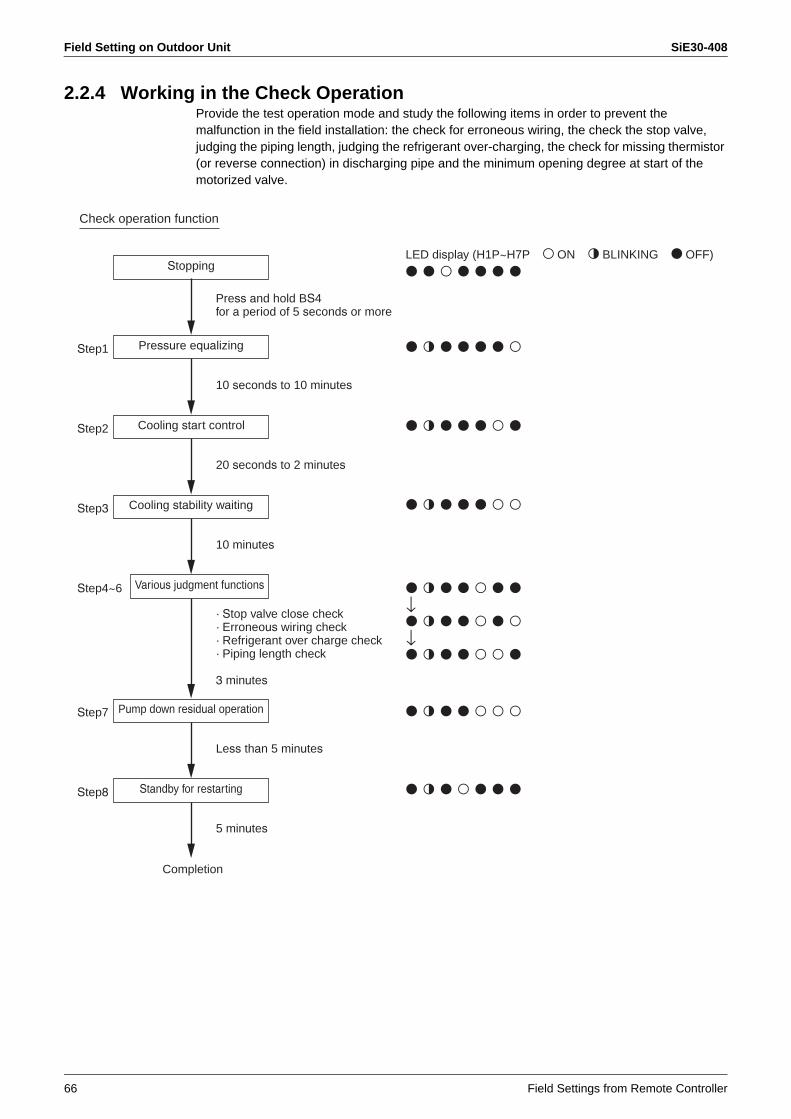
Field Setting on Outdoor Unit SiE30-408
66 Field Settings from Remote Controller
2.2.4 Working in the Check OperationProvide the test operation mode and study the following items in order to prevent the malfunction in the field installation: the check for erroneous wiring, the check the stop valve, judging the piping length, judging the refrigerant over-charging, the check for missing thermistor (or reverse connection) in discharging pipe and the minimum opening degree at start of the motorized valve.
Stopping
Pressure equalizing
Cooling start control
Cooling stability waiting
Various judgment functions
Pump down residual operation
Standby for restarting
Completion
7787777
7977778
7977787
7977788
7977888
7978777
7977877↓7977878↓7977887
Step1
Step2
10 seconds to 10 minutes
Step3
20 seconds to 2 minutes
Step4~6
10 minutes
Step7
Step8
Less than 5 minutes
5 minutes
LED display (H1P~H7P 8ON 9BLINKING 7OFF)
Check operation function
Press and hold BS4for a period of 5 seconds or more
· Stop valve close check· Erroneous wiring check· Refrigerant over charge check· Piping length check
3 minutes
SiE30-408
Troubleshooting 67
1. For Troubleshooting ..............................................................................682. Check Items before Troubleshooting ....................................................69
2.1 Check Items on Operation Condition (Essential Items as a Minimum) ..692.2 Check for Malfunction in Cooling Operation...........................................702.3 Check for Malfunction in Heating Operation...........................................71
3. Method of Troubleshooting ...................................................................723.1 Excessive / Insufficient Charging of Refrigerant.....................................723.2 Abnormal Judgment for Various Sensors...............................................753.3 Structure and Operation of Electronic Expansion Valve ........................833.4 Structure and Movements of Four-way Valve ........................................853.5 Structure and Operation of Solenoid Valve ............................................873.6 Structure and Operation of Two-way Solenoid Valve.............................883.7 Check on Outdoor Fan Motor.................................................................893.8 Diagnosis on Malfunction Code of Inverter System ...............................903.9 Diagnosis on Transmission System Malfunction....................................93
4. Malfunction Tree Analysis (FTA)...........................................................964.1 Actuation of Freeze-up Prevention Control of Indoor Unit......................974.2 Actuation of HPS in Heating Operation ..................................................984.3 Abnormal Discharge Pipe Temperature in Cooling Operation ...............994.4 Water Leakage from Indoor Unit ..........................................................1004.5 Defective Lubrication of Compressor ...................................................101
5. List of Malfunction Code......................................................................1026. Operating Condition Check Sheet.......................................................108
For Troubleshooting SiE30-408
68 Troubleshooting
1. For TroubleshootingEvery service engineer shall have consciousness, confidence, responsibility, and pride as a service person of manufacturer.
According to action patterns shown below, take prompt and on-target measures against defects or failures pointed out by customers.
1. Thoroughly listen to complaints or requests from customers.Hearing of complaints or requests from customersUnder what circumstances the customers will have complaints or be satisfied?• On what equipment, in which rooms or locations?• When? (→ In the evening, at the startup in the morning, while all units are in operation,
while a small number of units are in operation, or else)• Under what circumstances? (→ The system does not cool, water leakage or malfunction
occurs, or else)
2. Assume according to the contents of the hearing from customers and reproduce circumstances (or approximate circumstances) under which defects are caused to check the operating conditions. Furthermore, check the operating conditions under any other circumstances.Check the contents described in the attached check items on the operating conditions, and then record them in the operating condition check sheet (p.108).
3. Referring to the book of case examples, check to be sure whether applicable information is described.
4. Using the FTA technique, probe the causes of defects and narrow down the causes by a process of elimination.Referring to attached analysis on causes by FTA and samples, probe the causes of defects.
5. Take measures and check to be sure the conditions after the measures in the same manner as that under 2.‚ above.• Failures or defects in products → Rectify them by repair or adjustment.• Defects in construction area or facility design → Contact the request party. (Prompt
contact with the distribution channel.)
6. Explain customers about overview, contents of checks, results of checks, contents of measures, results of measures, and observations in plain expressions, have the customers accept the explanation, and then leave the site.
There are differences among individuals in product knowledge, know-how, and likes and dislikes. In order to enlist cooperation from other service engineers or sections, however, pin down and recap at least 1. to 3. out of items aforementioned. After that, with service engineer’s own observations added, the service engineer shall approach the customer.(Be sure to try to rectify the failure or defect himself.)

SiE30-408 Check Items before Troubleshooting
Troubleshooting 69
2. Check Items before Troubleshooting2.1 Check Items on Operation Condition (Essential Items as
a Minimum)
Check Items for Outdoor Unit
Model name of outdoor unitOutdoor temperature / Suction temperature of the outdoor unitHigh pressureLow pressureLiquid pressure (Measurement is required)Compressor discharge pipe temperatureCompressor suction pipe temperature (at the place near the low pressure sensor)Compressor capacity (* Hz + ON / OFF)Total capacity with indoor unit operation (with thermostat-ON)
Check Items for Each Indoor Unit
Model name of indoor unitSuction temperature (No. 41 on remote controller)Discharge temperature (Measure with thermometer)Set flow rate (Check with remote controller)Liquid pipe temperature (No. 41 on remote controller)Gas pipe temperature (No. 41 on remote controller)Opening degree of electronic expansion valve
Other Check Items
Number of indoor unit connected (Total capacity / Capacity ratio of indoor unit to outdoor unit)Approximate piping length, Additional refrigerant charged amountFrequency of occurrence of abnormality or malfunctionTiming of occurrence of abnormality or malfunction (Time band, etc.)Operating condition of the room (Number of units in operation or thermostat-ON)
Check the condition by preparing a state that resembles the state which has appeared at the time of malfunction.For the troubles occur occasionally or appear when the specified unit is operated, check the above items in each case of specified unit individual operation, other unit individual operation and all units operation.
* Check by using the "Operation condition check sheet" (P.108) for eliminating leakage of check item

Check Items before Troubleshooting SiE30-408
70 Troubleshooting
2.2 Check for Malfunction in Cooling OperationWhen cooling malfunctions, check on the following factors to specify the state of malfunction (peculiar on site). (In order to avoid an insufficient investigation at the initial check)
<At the time of ordinal operation, starting-up, oil return operation> Make sure that the timing of cooling malfunction generation.
If EV opening of all indoor units are the same degree, the instruction (control) for valve opening degree is sent from the outdoor unit.Make sure to grasp the state by using the checker.
Year round cooling Outdoor unit short circuit
· Low outdoor temperature control · High pressure stepping down (protection) control
· Low pressure stepping down (protection) control · Cooling overload control
Large pressure loss
Server, equipment room, etc.
· Actuation of freeze-up prevention · Cooling overload control
Low High
Low High
Small Large
Small Large
Outdoor temperature
Indoor temperature (WB)
Indoor unit operation capacity, EV opening degree
Piping length, difference in vertical level
Excessively heavy load,erroneous selection of model
Excessively light load, short circuited in indoor unit,erroneous selection of model
· For operation with the target evaporating temperatureor lower (Unbalance between load and control)
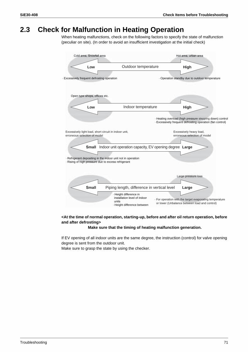
SiE30-408 Check Items before Troubleshooting
Troubleshooting 71
2.3 Check for Malfunction in Heating OperationWhen heating malfunctions, check on the following factors to specify the state of malfunction (peculiar on site). (In order to avoid an insufficient investigation at the initial check)
<At the time of normal operation, starting-up, before and after oil return operation, before and after defrosting>
Make sure that the timing of heating malfunction generation.
If EV opening of all indoor units are the same degree, the instruction (control) for valve opening degree is sent from the outdoor unit.Make sure to grasp the state by using the checker.
Cold area, Snowfall area Hot area, urban area
· Excessively frequent defrosting operation · Operation standby due to outdoor temperature
Open type shops, offices etc.
Large pressure loss
Low High
Low High
Small Large
Small Large
Outdoor temperature
Indoor temperature
Indoor unit operation capacity, EV opening degree
Piping length, difference in vertical level
· Height difference in installation level of indoor units
· Height difference between
· Heating overload (high pressure stepping down) control· Excessively frequent defrosting operation (fan control)
Excessively heavy load,erroneous selection of model
Excessively light load, short circuit in indoor unit,erroneous selection of model
· Refrigerant depositing in the indoor unit not in operation· Rising of high pressure due to excess refrigerant
· For operation with the target evaporating temperatureor lower (Unbalance between load and control)

Method of Troubleshooting SiE30-408
72 Troubleshooting
3. Method of Troubleshooting3.1 Excessive / Insufficient Charging of Refrigerant
For VRV system, troubleshooting can be executed only with the operating conditions of air conditioner relating to pressure control and electronic expansion valve control, and the methods of judgment are shown below.
1. For excessive charging(The operating capacity of compressor has a tendency to increase in cooling while decrease in heating.)1. Operate with light load by using capacity control of compressor due to increasing of high
pressure (condensing temperature).(Compressor capacity cannot be controlled to obtain the target pressure.)As a result, circulation volume of refrigerant decreases, and cooling and heating will malfunction.
2. In heating operation, since a large amount of liquid refrigerant is stagnant between the outlet of condenser and the liquid line, the cooling temperature of refrigerant become large and discharge air temperature lowers even when the target pressure (see below) is maintained in heating operation. Moreover, the detecting temperature of liquid pipe thermistor in indoor unit may be kept at approx. 40°C or higher normally, while in this case, the temperature may lower to approx. 35°C or lower due to a stagnancy of refrigerant. Accordingly, the discharge temperature may become approx. 30°C.
3. In heating operation, the control is executed during closing operation of EV opening degree.Since the liquid pressure rises with the rising high pressure, even if the EV is throttled to the minimum opening degree (200 pls), refrigerant cannot be super heated at the outlet of heat exchanger and liquid refrigerant which does not evaporate returns to compressor, resulting an operation so called "wet operation".• Superheated degree = 0 → The discharge pipe temperature lowers.
(Condensing temperature + 20°C or less)
2. For insufficient charging(The operating capacity of compressor has a tendency to decrease in cooling while increase in heating.)1. The discharge pipe temperature of compressor rises. (Suction SH increases, and
discharge pipe temperature also increases.)2. Refrigerant at the outlet of evaporator is superheated. (Electronic expansion valve will be
opened fully.)In this case, for the suction superheat degree of compressor is increased, alarm display of insufficient gas (U0) is displayed.
3. In cooling operation, when the operation capacity of compressor is small, since the low pressure (evaporating pressure) is low against refrigerant load, the unit cannot be operated with required capacity due to decreasing of refrigerant circulation volume. In heating operation, it is required to check that the difference between high pressure and liquid pressure is 0.3 to 0.4 MPa.Due to the characteristic of expansion valve, refrigerant cannot flow easily when the pressure difference between inlet and outlet of the valve is 0.2 MPa or more, therefore, liquid refrigerant will be stagnant between indoor heat exchanger and liquid piping.Large pressure difference → Shortage of refrigerantSmall pressure difference → Excessive charge of refrigerant
Target Pressure and Temperature
* Above target temperature stands for the saturation temperature at gas side.
Target condensing temperature / High pressure
Target evaporating temperature / Low pressure
R22 46°C 1.8MPa 5.5°C 0.59MPa
R407C 48°C 1.9MPa 7.5°C 0.58MPa
R410A 46°C 2.8MPa 6.0°C 0.96MPa

SiE30-408 Method of Troubleshooting
Troubleshooting 73
3.1.1 Change of High / Low Pressure and Frequency with Excessive / Insufficient Refrigerant Gas Charge (Presentation with Image)
[For operation with all units connected (100 %)]1. Excessively Charged Refrigerant Gas
å~áº
Cooling
High pressure
Low pressure
Frequency
High pressure
Low pressure
Frequency
Heating
No status change within the range that the receiver can absorb the refrigerant.
High pressure stepping down control
Progress of excessive gas charging
Outdoor electronic expansion valve closes due to overload control.
High pressure risesgradually with increasingof frequency.
For maintaining of low pressure, capacity control shall be conducted resulting frequency rising.
(High pressure is maintainedconstant.)
Low pressure rises due to lowering of frequency.
Low pressure lowers due to closing of outdoor motorized valve.Hot gas bypass actuates with low pressure protection = actually, low pressure hunting will be generated.
For maintaining of high pressure, capacity control shall be conductedresulting frequency lowering.
(Low pressure ismaintained constant.)
No status change within the rangethat the receiver can absorb the refrigerant
Frequency becomes to the minimum.
Frequency becomes to the minimum.
Subcooled degree increases. (Temperature drops in liquid connection piping)
Low pressure rises due to decreasingof compressor output.
High pressure lowers immediatelyafter the overload control.

Method of Troubleshooting SiE30-408
74 Troubleshooting
2. Insufficient Refrigerant Gas
Opening degree of indoor electronic expansion valve increases.
Any one of motorized valve is fully open.
Opening degree of indoor electronic expansion valve increases.
Outdoor electronic expansion valve is opened fully, and frequency increases.
Discharge pipe or low-pressure stepping down control
Frequency becomes to the minimum.
Progress of gas shortage
å~áº
Cooling
High pressure
Low pressure
Frequency
High pressure
Low pressure
Frequency
Heating
Fan control will be executed for maintaining high pressure with low outdoor temperature cooling control = Actually, hunting will be generated.
High pressure lowers due to decreasing of compressorcapacity.
Low pressure rises due to large opening degree of indoor electronic expansion valve, andfrequency increases a little with capacity control. Low pressure cannot be maintained
when frequency becomes the minimum.
For maintaining of low pressure, capacity control shall be conductedresulting frequency lowering.
(High pressure ismaintained constant.)
For maintaining of low pressure, capacity control shall beconducted resulting frequencylowering.
Frequency lowers due to stepping down control.
(Low pressure ismaintained constant.)
Frequency becomes to the minimum.

SiE30-408 Method of Troubleshooting
Troubleshooting 75
3.2 Abnormal Judgment for Various SensorsWhen pressure sensor, thermistor or current sensor detects an abnormal value (upper limit value or more, or lower limit value or less), the unit will be halted with display of "Abnormal cord". [Abnormal stop]
Outdoor Unit
Indoor Unit
Sensor nameR22 model R407C model R410A model
Malfunction codeElectronic
symbolUpper limit
valueLower limit
valueElectronic
symbolUpper limit
valueLower limit
valueElectronic
symbolUpper limit
valueLower limit
value
High-pressure sensor SENPH 71.4°C –40.5°C SENPH 74.4°C –35.7°C SINPH 43kg/cm2
0.1kg/cm2 JA
Low-pressure sensor SENPL 26.8°C –53.5°C SENPL 32.7°C –39.6°C SINPL 18kg/cm2
–0.1kg/cm2 JC
Outdoor air thermistor Th1 90.0°C –43.7°C R1T 90.0°C –43.6°C R1T 90.0°C –43.6°C H9
Heat exchanger thermistor Th2 90.0°C –43.7°C R2T 90.0°C –43.6°C R4T 90.0°C –43.6°C J6
Discharge pipe thermistor(For INV)
Th3-1 196.0°C –10.2°C R3-1T 165.0°C –20.0°C R31T 165.0°C –20.0°C J3
Discharge pipe thermistor(For STD)
Th3-2 196.0°C –10.2°C R3-2T 165.0°C –20.0°C R32T 165.0°C –20.0°C J3
Suction pipe thermistor Th4 90.0°C –10.2°C R6T 90.0°C –43.6°C R2T 90.0°C –43.6°C J5
Oil temperature thermistor(For INV)
Th5-1 90.0°C –10.2°C — — — — — — JH
Oil temperature thermistor(For STD)
Th5-2 90.0°C –10.2°C — — — — — — JH
Header thermistor Th6 90.0°C –10.2°C R4T 90.0°C –43.6°C 90.0°C –43.6°C J7
Current sensor — — — T1A 40A 5A T1A 40A 5A J2
Applicable models RXY ~ K(A)RNY ~ K(A)
RXYP ~ KRSXYP ~ L RXY(Q) ~ M —
Sensor nameR22 model R407C model R410A model
Malfunction codeElectronic
symbolUpper limit
valueLower limit
valueElectronic
symbolUpper limit
valueLower limit
valueElectronic
symbolUpper limit
valueLower limit
value
Heat exchanger liquid pipe thermistor Th2 120°C –50°C Th2 120°C –50°C R2T 120°C –50°C C4
Heat exchanger gas pipe thermistor Th3 120°C –50°C Th3 120°C –50°C R3T 120°C –50°C C5
Suction air thermistor Th1 130°C –40°C Th1 130°C –40°C R1T 130°C –40°C C9
Discharge air thermistor Th4 130°C –40°C Th4 130°C –40°C R4T 130°C –40°C CA
Remote controller thermistor for suction air
Th 130°C –40°C Th 130°C –40°C R1T 130°C –40°C CJ
Applicable models G ~ KA type P ~ K type Q ~ M type —

Method of Troubleshooting SiE30-408
76 Troubleshooting
3.2.1 Thermistor
1. Symptoms with Thermistor Resistance Deviation
In Cooling with Superheat Degree Control
Code of Thermistors Detecting Various Temperatures
Units using R22, R407C Units using R410A
Tl (indoor liquid pipe temperature) Th2 R2T
Tg (indoor gas pipe temperature) Th3 R3T
Superheat degree (SH) = Tg-Tl
Tg-Tl decreases.
Indoor electronic EV closes.
Superheated degree (SH) = Tg-Tl
Tg-Tl increases.
Indoor electronic EV opens.
Superheat operation, cooling capacity lowering (Freeze-upprotection cannot be detected.)
Wet operation (Freeze-upprotection can be appliedeasily.)
Superheated degree (SH) = Tg-Tl
Tg-Tl increases.
Indoor electronic EV opens.
Wet operation
Superheat degree (SH) = Tg-Tl
Tg-Tl decreases.
Indoor electronic EV closes.
• Indoor unit liquid pipe thermistor· When the resistance deviates to smaller value.
(Higher temperature detected)
• Indoor gas pipe thermistor· When the resistance deviates to smaller value.
(Higher temperature detected)
· When the resistance deviates to larger value. (Lower temperature detected)
· When the resistance deviates to larger value. (Lower temperature detected)
Superheat operation,cooling capacity lowering

SiE30-408 Method of Troubleshooting
Troubleshooting 77
In Heating with Subcooled Degree Control
In ON / OFF Judgment for Heating Hot Start
Subcooled degree (SC) = Tc-Tl Subcooled degree (SC) = Tc-Tl
Indoor electronic extensionvalve closes.
Indoor electronic extensionvalve opens.
Liquid refrigerant is stagnant in indoor heat exchanger. (High pressure rises due to heating overload.)
Refrigerant delivery among indoor units cannot be balanced.
• Indoor unit liquid pipe thermistor· When the resistance deviates to smaller value.
(Higher temperature detected)
Tc-Tl decreases.(Subcooling does not work.)
Tc-Tl increases.(Subcooling works excessively.)
· When the resistance deviates to larger value. (Lower temperature detected)
Tl ≤ 35 °C is detected.
Hot start cancellation delays. (For 3 minutes or less)
Insufficient capacity for start-up
• Indoor unit liquid pipe thermistor· When the resistance deviates to larger value.
(Lower temperature detected)
Condition for canceling hot startTl ≥ 35 °C or 3 minutes elapse from thermostat ON.
Tc: Equivalent saturation temperature of detected value of outdoor high pressure sensor (Pc)Tl: Detected temperature of indoor liquid pipe thermistor (Th2 for units using R22 or R407C, R2T for units using R410A)
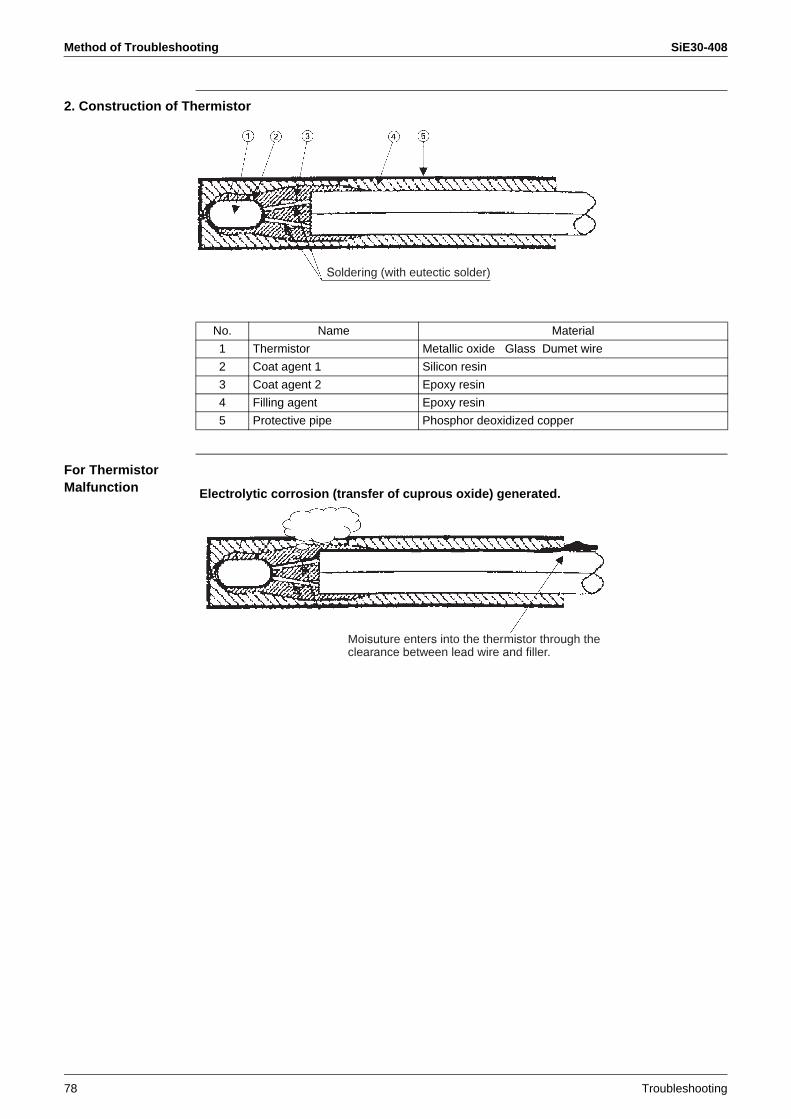
Method of Troubleshooting SiE30-408
78 Troubleshooting
2. Construction of Thermistor
For Thermistor Malfunction
Soldering (with eutectic solder)
No. Name Material
1 Thermistor Metallic oxide Glass Dumet wire
2 Coat agent 1 Silicon resin
3 Coat agent 2 Epoxy resin
4 Filling agent Epoxy resin
5 Protective pipe Phosphor deoxidized copper
Moisuture enters into the thermistor through the clearance between lead wire and filler.
Electrolytic corrosion (transfer of cuprous oxide) generated.
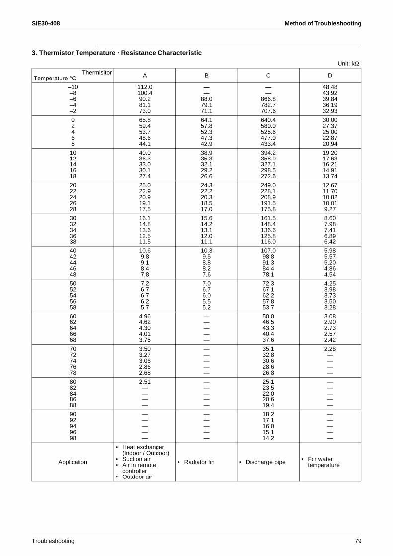
SiE30-408 Method of Troubleshooting
Troubleshooting 79
3. Thermistor Temperature · Resistance Characteristic
Unit: kΩThermisitor
Temperature °C A B C D
–10–8–6–4–2
112.0100.490.281.173.0
——
88.079.171.1
——
866.8782.7707.6
48.4843.9239.8436.1932.93
02468
65.859.453.748.644.1
64.157.852.347.342.9
640.4580.0525.6477.0433.4
30.0027.3725.0022.8720.94
1012141618
40.036.333.030.127.4
38.935.332.129.226.6
394.2358.9327.1298.5272.6
19.2017.6316.2114.9113.74
2022242628
25.022.920.919.117.5
24.322.220.318.517.0
249.0228.1208.9191.5175.8
12.6711.7010.8210.019.27
3032343638
16.114.813.612.511.5
15.614.213.112.011.1
161.5148.4136.6125.8116.0
8.607.987.416.896.42
4042444648
10.69.89.18.47.8
10.39.58.88.27.6
107.098.891.384.478.1
5.985.575.204.864.54
5052545658
7.26.76.76.25.7
7.06.76.05.55.2
72.367.162.257.853.7
4.253.983.733.503.28
6062646668
4.964.624.304.013.75
—————
50.046.543.340.437.6
3.082.902.732.572.42
7072747678
3.503.273.062.862.68
—————
35.132.830.628.626.8
2.28————
8082848688
2.51————
—————
25.123.522.020.619.4
—————
9092949698
—————
—————
18.217.116.015.114.2
—————
Application
• Heat exchanger (Indoor / Outdoor)
• Suction air• Air in remote
controller• Outdoor air
• Radiator fin • Discharge pipe • For water temperature

Method of Troubleshooting SiE30-408
80 Troubleshooting
3.2.2 Pressure Sensor
1. Voltage Measuring Point
When the color of harness is not as mentioned above, find the measuring point by following procedure.1. Black is GND.2. Find DC5V line.3. The remained wire is the sensing section.
(For the same pressure, higher output voltage can be detected with low-pressure sensor, while lower output voltage detected with high pressure sensor.)
Outdoor PC board
(Blue)+5V
LP p
ress
ure
sens
orRed
Black
Green
White
Micro control A / D input
Measure voltage (DC) between these pins.
Outdoor PC board
Connector for high-pressure sensor(Red)+5V
LP p
ress
ure
sens
orRed
Black
Green
WhiteMicro control A / D input
Measure voltage (DC) between these pins.
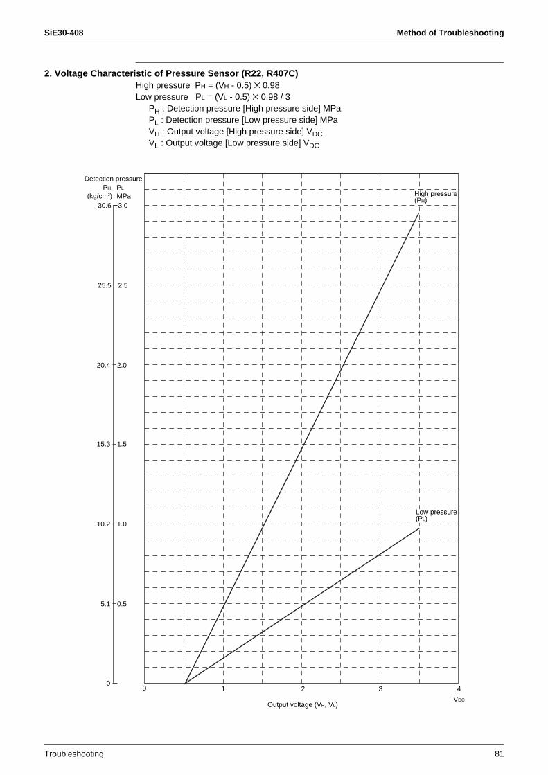
SiE30-408 Method of Troubleshooting
Troubleshooting 81
2. Voltage Characteristic of Pressure Sensor (R22, R407C)High pressure PH = (VH - 0.5) × 0.98Low pressure PL = (VL - 0.5) × 0.98 / 3
PH : Detection pressure [High pressure side] MPaPL : Detection pressure [Low pressure side] MPaVH : Output voltage [High pressure side] VDCVL : Output voltage [Low pressure side] VDC
Output voltage (VH, VL)
0
5.1 0.5
0 1 2 3 4
VDC
10.2 1.0
15.3 1.5
30.6 3.0
25.5 2.5
20.4 2.0
(kg/cm2) MPa
Detection pressurePH, PL
High pressure(PH)
Low pressure(PL)
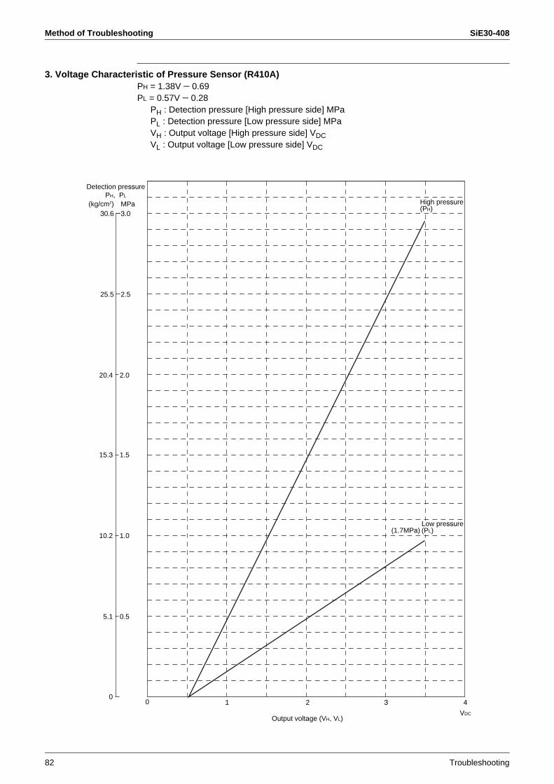
Method of Troubleshooting SiE30-408
82 Troubleshooting
3. Voltage Characteristic of Pressure Sensor (R410A)PH = 1.38V − 0.69PL = 0.57V − 0.28
PH : Detection pressure [High pressure side] MPaPL : Detection pressure [Low pressure side] MPaVH : Output voltage [High pressure side] VDCVL : Output voltage [Low pressure side] VDC
Output voltage (VH, VL)
0
5.1 0.5
0 1 2 3 4
VDC
10.2 1.0
15.3 1.5
30.6 3.0
25.5 2.5
20.4 2.0
(kg/cm2) MPa
(1.7MPa)
Detection pressurePH, PL
High pressure(PH)
Low pressure(PL)
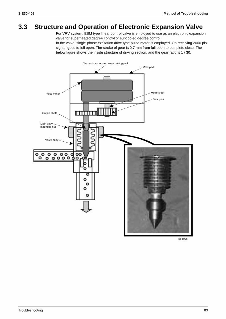
SiE30-408 Method of Troubleshooting
Troubleshooting 83
3.3 Structure and Operation of Electronic Expansion ValveFor VRV system, EBM type linear control valve is employed to use as an electronic expansion valve for superheated degree control or subcooled degree control.In the valve, single-phase excitation drive type pulse motor is employed. On receiving 2000 pls signal, goes to full open. The stroke of gear is 0.7 mm from full open to complete close. The below figure shows the inside structure of driving section, and the gear ratio is 1 / 30.
Electronic expansion valve driving part
Pulse motor
Output shaft
Main bodymounting nut
Valve body
Motor shaft
Gear part
Bellows
Mold part

Method of Troubleshooting SiE30-408
84 Troubleshooting
3.3.1 Malfunction Example of Electronic Expansion ValveGas Leakage Malfunction (Full Open)
Malfunction (Complete Close)
Gas leakage
Moisture entered into the bellows due to the following causes, and froze resultingbreak of the bellows.· Inadequate fastening torque
for the nut· Deterioration of the packing
Crack is found in bellows.
Gears run idle due to wear of gear teeth.
Full refrigerant gasin driving section
The valve is protruded excessively into the valve seat.
When driving section of electronic expansion valve isremoved during operation, default setting (initialize) shifted and the output shaft may be incorrect position. If this operation is repeated, protrusion of valve cannotbe returned.Above cause of the trouble may be result leakage of motorized valve (inner leakage).
When electronic expansion valve is removed during the unit is operated, make sure to conduct initializationbefore ending of the work.
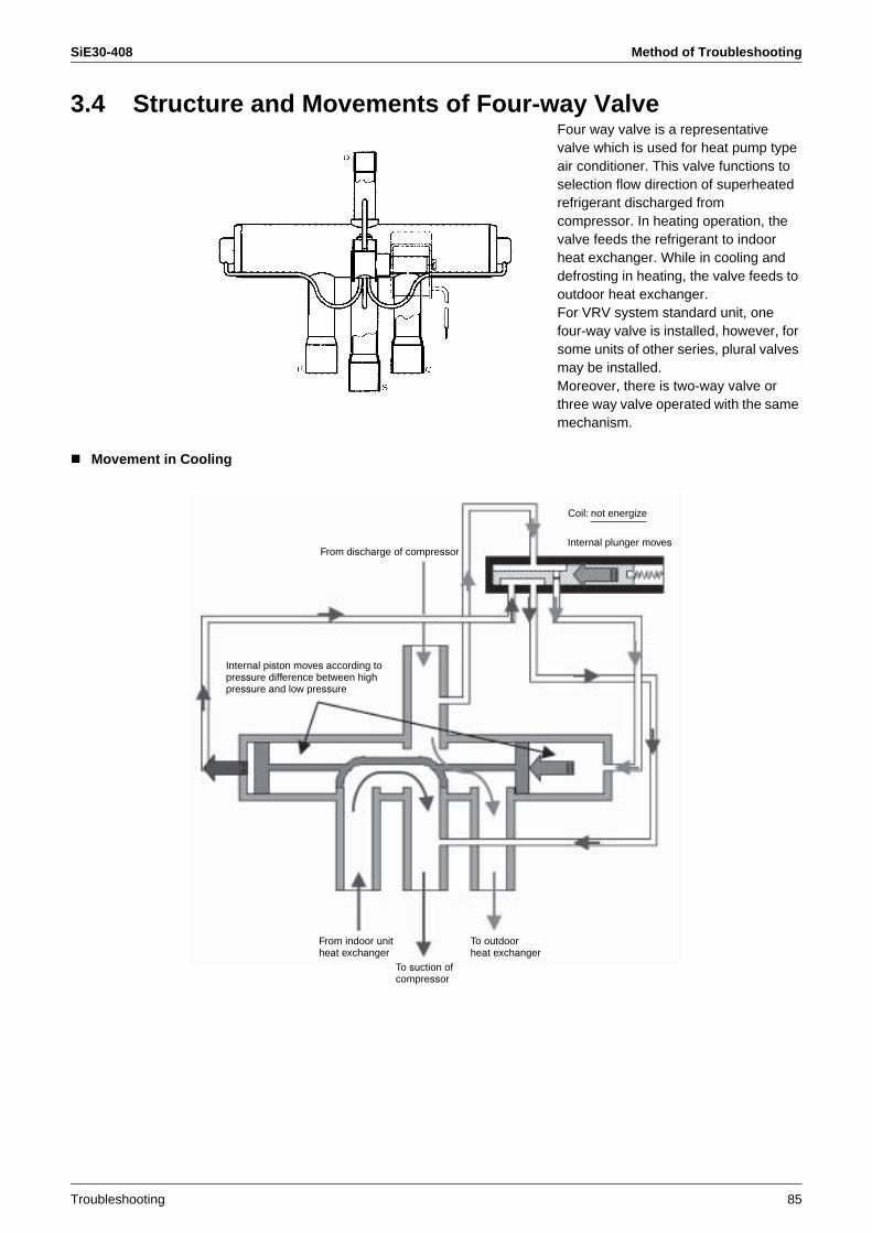
SiE30-408 Method of Troubleshooting
Troubleshooting 85
3.4 Structure and Movements of Four-way ValveFour way valve is a representative valve which is used for heat pump type air conditioner. This valve functions to selection flow direction of superheated refrigerant discharged from compressor. In heating operation, the valve feeds the refrigerant to indoor heat exchanger. While in cooling and defrosting in heating, the valve feeds to outdoor heat exchanger.For VRV system standard unit, one four-way valve is installed, however, for some units of other series, plural valves may be installed.Moreover, there is two-way valve or three way valve operated with the same mechanism.
Movement in Cooling
From discharge of compressor
Coil: not energize
Internal plunger moves
Internal piston moves according to pressure difference between high pressure and low pressure
To outdoorheat exchanger
To suction of compressor
From indoor unitheat exchanger
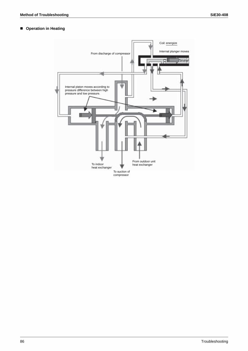
Method of Troubleshooting SiE30-408
86 Troubleshooting
Operation in Heating
From discharge of compressor
Internal piston moves according to pressure difference between high pressure and low pressure.
Coil: energize
Internal plunger moves
To indoor heat exchanger
To suction of compressor
From outdoor unitheat exchanger
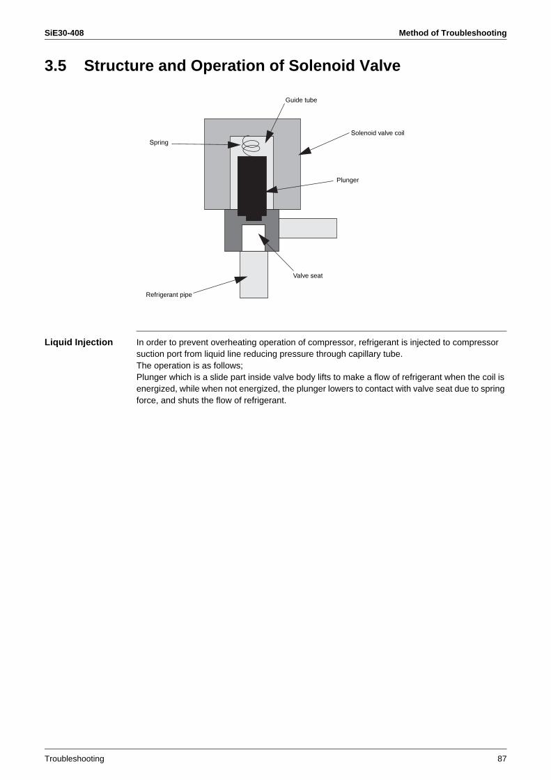
SiE30-408 Method of Troubleshooting
Troubleshooting 87
3.5 Structure and Operation of Solenoid Valve
Liquid Injection In order to prevent overheating operation of compressor, refrigerant is injected to compressor suction port from liquid line reducing pressure through capillary tube. The operation is as follows;Plunger which is a slide part inside valve body lifts to make a flow of refrigerant when the coil is energized, while when not energized, the plunger lowers to contact with valve seat due to spring force, and shuts the flow of refrigerant.
Guide tube
Spring
Refrigerant pipe
Valve seat
Plunger
Solenoid valve coil
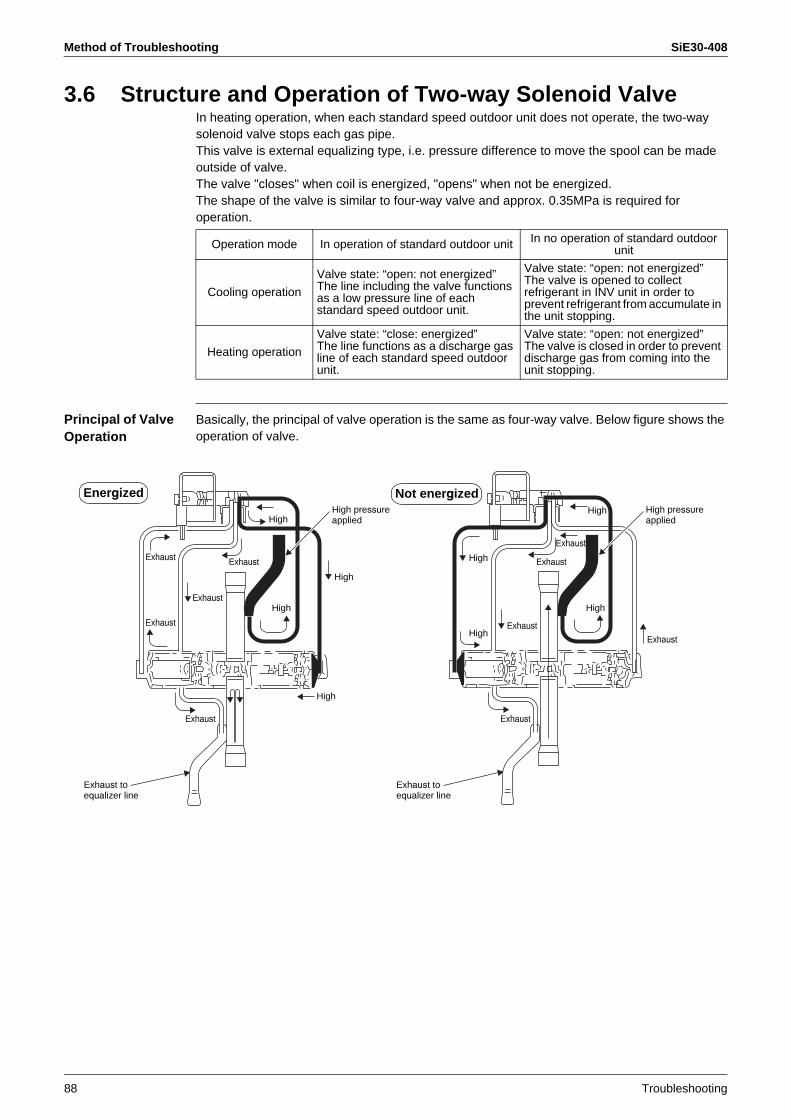
Method of Troubleshooting SiE30-408
88 Troubleshooting
3.6 Structure and Operation of Two-way Solenoid ValveIn heating operation, when each standard speed outdoor unit does not operate, the two-way solenoid valve stops each gas pipe.This valve is external equalizing type, i.e. pressure difference to move the spool can be made outside of valve.The valve "closes" when coil is energized, "opens" when not be energized.The shape of the valve is similar to four-way valve and approx. 0.35MPa is required for operation.
Principal of Valve Operation
Basically, the principal of valve operation is the same as four-way valve. Below figure shows the operation of valve.
Operation mode In operation of standard outdoor unit In no operation of standard outdoor unit
Cooling operation
Valve state: “open: not energized” The line including the valve functions as a low pressure line of each standard speed outdoor unit.
Valve state: “open: not energized”The valve is opened to collect refrigerant in INV unit in order to prevent refrigerant from accumulate in the unit stopping.
Heating operation
Valve state: “close: energized” The line functions as a discharge gas line of each standard speed outdoor unit.
Valve state: “open: not energized” The valve is closed in order to prevent discharge gas from coming into the unit stopping.
Energized Not energized
Exhaust
Exhaust
Exhaust
Exhaust
Exhaust
Exhaust
Exhaust
Exhaust
Exhaust
Exhaust
High
High
High
High
High
High
High
High
High pressureapplied
Exhaust to equalizer line
Exhaust to equalizer line
High pressureapplied
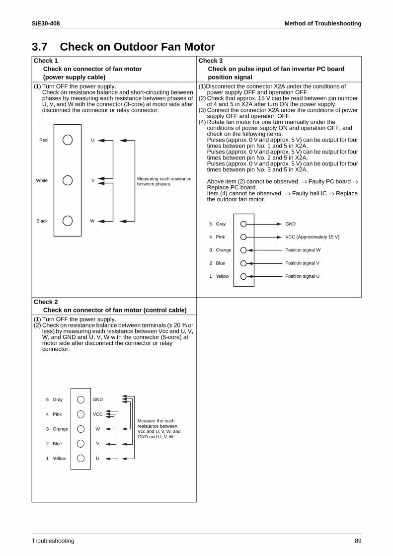
SiE30-408 Method of Troubleshooting
Troubleshooting 89
3.7 Check on Outdoor Fan MotorCheck 1
Check on connector of fan motor (power supply cable)
Check 3Check on pulse input of fan inverter PC board position signal
(1) Turn OFF the power supply.Check on resistance balance and short-circuiting between phases by measuring each resistance between phases of U, V, and W with the connector (3-core) at motor side after disconnect the connector or relay connector.
(1)Disconnect the connector X2A under the conditions of power supply OFF and operation OFF.
(2) Check that approx. 15 V can be read between pin number of 4 and 5 in X2A after turn ON the power supply.
(3) Connect the connector X2A under the conditions of power supply OFF and operation OFF.
(4) Rotate fan motor for one turn manually under the conditions of power supply ON and operation OFF, and check on the following items.Pulses (approx. 0 V and approx. 5 V) can be output for four times between pin No. 1 and 5 in X2A.Pulses (approx. 0 V and approx. 5 V) can be output for four times between pin No. 2 and 5 in X2A.Pulses (approx. 0 V and approx. 5 V) can be output for four times between pin No. 3 and 5 in X2A.
Above item (2) cannot be observed. → Faulty PC board →Replace PC board.Item (4) cannot be observed. → Faulty hall IC → Replace the outdoor fan motor.
Check 2Check on connector of fan motor (control cable)
(1) Turn OFF the power supply.(2) Check on resistance balance between terminals (± 20 % or
less) by measuring each resistance between Vcc and U, V, W, and GND and U, V, W with the connector (5-core) at motor side after disconnect the connector or relay connector.
Red
White
Black
U
V
W
Measuring each resistancebetween phases
5 Gray
4 Pink
3 Orange
2 Blue
1 Yellow
GND
VCC (Approximately 15 V)
Position signal W
Position signal V
Position signal U
Measure the eachresistance between Vcc and U, V, W, andGND and U, V, W.
5 Gray
4 Pink
3 Orange
2 Blue
1 Yellow
GND
VCC
W
V
U
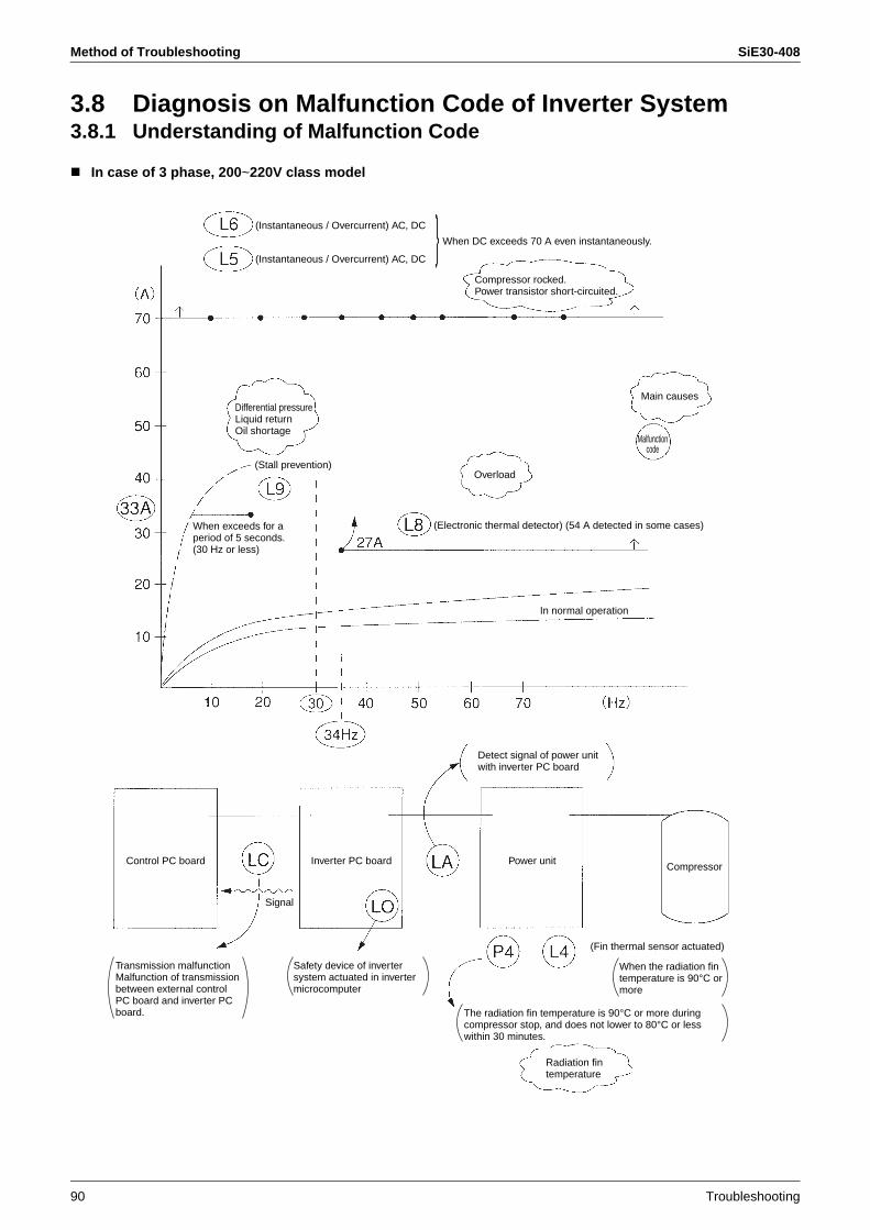
Method of Troubleshooting SiE30-408
90 Troubleshooting
3.8 Diagnosis on Malfunction Code of Inverter System3.8.1 Understanding of Malfunction Code
In case of 3 phase, 200~220V class model
When DC exceeds 70 A even instantaneously.
(Stall prevention)
When exceeds for a period of 5 seconds. (30 Hz or less)
Overload
(Electronic thermal detector) (54 A detected in some cases)
Main causes
In normal operation
Control PC board Inverter PC board Power unitCompressor
Signal
Transmission malfunctionMalfunction of transmission between external control PC board and inverter PC board.
Safety device of inverter system actuated in inverter microcomputer
The radiation fin temperature is 90°C or more during compressor stop, and does not lower to 80°C or less within 30 minutes.
When the radiation fin temperature is 90°C or more
(Fin thermal sensor actuated)
(Instantaneous / Overcurrent) AC, DC
(Instantaneous / Overcurrent) AC, DC
Compressor rocked.Power transistor short-circuited.
Differential pressureLiquid returnOil shortage
Malfunctioncode
Detect signal of power unit with inverter PC board
Radiation fin temperature
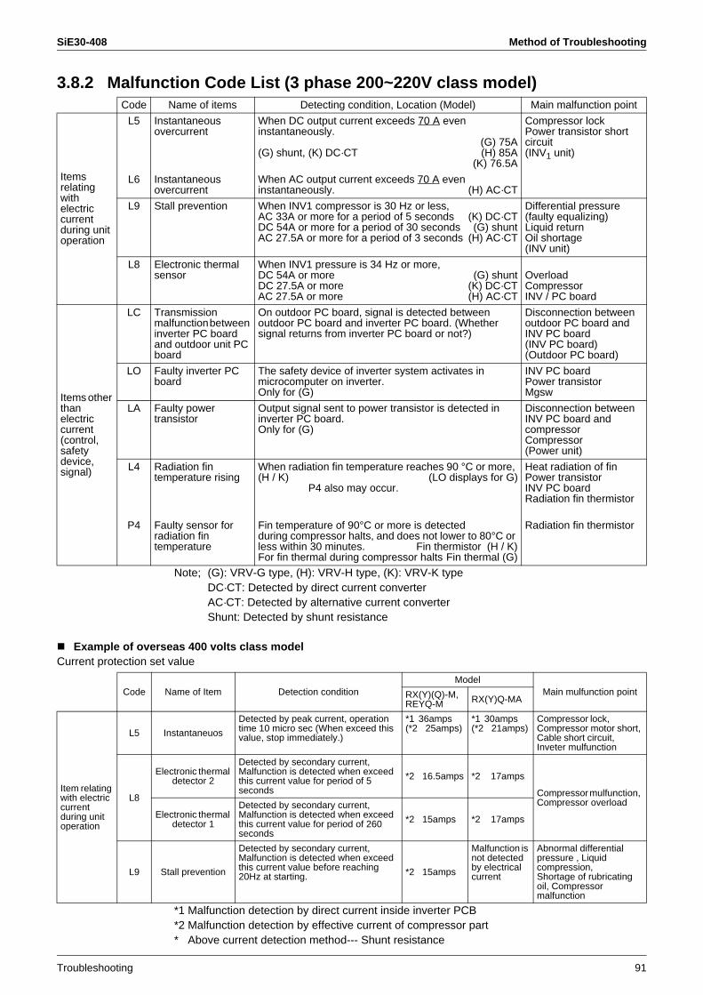
SiE30-408 Method of Troubleshooting
Troubleshooting 91
3.8.2 Malfunction Code List (3 phase 200~220V class model)
Note; (G): VRV-G type, (H): VRV-H type, (K): VRV-K typeDC·CT: Detected by direct current converterAC·CT: Detected by alternative current converterShunt: Detected by shunt resistance
Example of overseas 400 volts class modelCurrent protection set value
*1 Malfunction detection by direct current inside inverter PCB*2 Malfunction detection by effective current of compressor part* Above current detection method--- Shunt resistance
Code Name of items Detecting condition, Location (Model) Main malfunction point
Items relating withelectric currentduring unit operation
L5 Instantaneous overcurrent
When DC output current exceeds 70 A even instantaneously.
(G) 75A(G) shunt, (K) DC·CT (H) 85A
(K) 76.5A
Compressor lockPower transistor short circuit(INV1 unit)
L6 Instantaneous overcurrent
When AC output current exceeds 70 A even instantaneously. (H) AC·CT
L9 Stall prevention When INV1 compressor is 30 Hz or less,AC 33A or more for a period of 5 seconds (K) DC·CTDC 54A or more for a period of 30 seconds (G) shuntAC 27.5A or more for a period of 3 seconds (H) AC·CT
Differential pressure (faulty equalizing)Liquid returnOil shortage(INV unit)
L8 Electronic thermal sensor
When INV1 pressure is 34 Hz or more,DC 54A or more (G) shuntDC 27.5A or more (K) DC·CTAC 27.5A or more (H) AC·CT
OverloadCompressorINV / PC board
Items other thanelectric current(control,safetydevice, signal)
LC Transmission malfunction between inverter PC board and outdoor unit PC board
On outdoor PC board, signal is detected between outdoor PC board and inverter PC board. (Whether signal returns from inverter PC board or not?)
Disconnection between outdoor PC board and INV PC board(INV PC board)(Outdoor PC board)
LO Faulty inverter PC board
The safety device of inverter system activates in microcomputer on inverter.Only for (G)
INV PC boardPower transistorMgsw
LA Faulty power transistor
Output signal sent to power transistor is detected in inverter PC board.Only for (G)
Disconnection between INV PC board and compressorCompressor(Power unit)
L4 Radiation fin temperature rising
When radiation fin temperature reaches 90 °C or more, (H / K) (LO displays for G)
P4 also may occur.
Heat radiation of finPower transistorINV PC boardRadiation fin thermistor
P4 Faulty sensor for radiation fin temperature
Fin temperature of 90°C or more is detectedduring compressor halts, and does not lower to 80°C or less within 30 minutes. Fin thermistor (H / K)For fin thermal during compressor halts Fin thermal (G)
Radiation fin thermistor
Code Name of Item Detection conditionModel
Main mulfunction pointRX(Y)(Q)-M, REYQ-M RX(Y)Q-MA
Item relating with electric current during unit operation
L5 Instantaneuos
Detected by peak current, operation time 10 micro sec (When exceed this value, stop immediately.)
*1 36amps (*2 25amps)
*1 30amps (*2 21amps)
Compressor lock, Compressor motor short, Cable short circuit, Inveter mulfunction
L8
Electronic thermal detector 2
Detected by secondary current, Malfunction is detected when exceed this current value for period of 5 seconds
*2 16.5amps *2 17amps
Compressor mulfunction, Compressor overload
Electronic thermal detector 1
Detected by secondary current, Malfunction is detected when exceed this current value for period of 260 seconds
*2 15amps *2 17amps
L9 Stall prevention
Detected by secondary current, Malfunction is detected when exceed this current value before reaching 20Hz at starting. *2 15amps
Malfunction is not detected by electrical current
Abnormal differential pressure , Liquid compression, Shortage of rubricating oil, Compressor malfunction

Method of Troubleshooting SiE30-408
92 Troubleshooting
3.8.3 How to Use Monitor on Inverter PC BoardThe latest contents of malfunction stop can be obtained by LED display on inverter PC board.Each malfunction stop of inverter has retry function. Within the specified frequency of retry, the unit merely goes into 5 minutes standby mode, and malfunction cannot be determined.When the retry frequency completes within 60 minutes, malfunction is determined and malfunction code will be displayed on indoor remote controller.
9: BLINK8: ON7: OFF
LED A 1 2 3 4 Malfunction contents Number of retry times
97777 Normal —
97778 Malfunction of fin thermal 3
98877 Malfunction of sensor system 0
98778 Voltage shortage 3
97787 Instantaneous overcurrent 3
97888 Electronic thermal 3
98888 Stall prevention 3
97877 Open phase detection 3
77777 Microcomputer malfunction Infinite
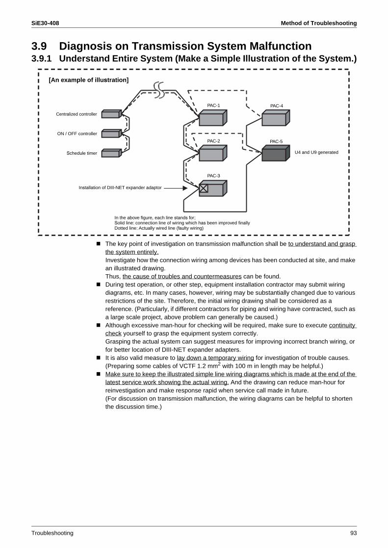
SiE30-408 Method of Troubleshooting
Troubleshooting 93
3.9 Diagnosis on Transmission System Malfunction3.9.1 Understand Entire System (Make a Simple Illustration of the System.)
The key point of investigation on transmission malfunction shall be to understand and grasp the system entirely.Investigate how the connection wiring among devices has been conducted at site, and make an illustrated drawing.Thus, the cause of troubles and countermeasures can be found.During test operation, or other step, equipment installation contractor may submit wiring diagrams, etc. In many cases, however, wiring may be substantially changed due to various restrictions of the site. Therefore, the initial wiring drawing shall be considered as a reference. (Particularly, if different contractors for piping and wiring have contracted, such as a large scale project, above problem can generally be caused.)Although excessive man-hour for checking will be required, make sure to execute continuity check yourself to grasp the equipment system correctly.Grasping the actual system can suggest measures for improving incorrect branch wiring, or for better location of DIII-NET expander adapters.It is also valid measure to lay down a temporary wiring for investigation of trouble causes.(Preparing some cables of VCTF 1.2 mm2 with 100 m in length may be helpful.)Make sure to keep the illustrated simple line wiring diagrams which is made at the end of the latest service work showing the actual wiring. And the drawing can reduce man-hour for reinvestigation and make response rapid when service call made in future.(For discussion on transmission malfunction, the wiring diagrams can be helpful to shorten the discussion time.)
[An example of illustration]
Installation of DIII-NET expander adaptor
PAC-1 PAC-4
PAC-5PAC-2
PAC-3
U4 and U9 generated
Centralized controller
ON / OFF controller
Schedule timer
In the above figure, each line stands for;Solid line: connection line of wiring which has been improved finallyDotted line: Actually wired line (faulty wiring)
Method of Troubleshooting SiE30-408
94 Troubleshooting
3.9.2 Cautions in Transmitting Waveform MeasurementMake sure the probe is securely connected to respective terminals (F1 and F2)Playing on either of the terminals may deform the waveform, thus resulting in incorrect diagnosis.In order to acquire proper diagnosis, be sure to connect a temporary distributing cable to the probe and fix it to the F1 and F2 with screws.There are several types of waveforms (for sending and receiving). Therefore, the acquirement of only one waveform remains many things unknown.Commit yourself to data reduction. → Record waveforms as soon as acquired so as to recognize at which points the waveforms have been acquired.It is useful for measurements to provide a temporary distributing cable.
3.9.3 Measurement RangeBasically, time axis (lateral axis): 50 µs to 100 µsvoltage axis (longitudinal axis): 2 V to 5 VFor oscilloscope, acquire waveforms with the "trigger" set to NORMAL mode for easy reading. (By setting the trigger to AUTO mode, waveforms displayed may immediately disappear.)For MEMORY HiCORDER, set all the "filters" to OFF. (Setting the filter to ON may recognize waveforms as noise, thus resulting in no display.)In common with the oscilloscope and MEMORY HiCORDER, pay attention to the "POSITION". (Neglecting the position may conceal waveforms to the point of invisibility in upper or lower portion of the screen.)It is useful for measurement to provide AC mode for sampling mode. (Waveforms will be displayed in the center of the screen.)
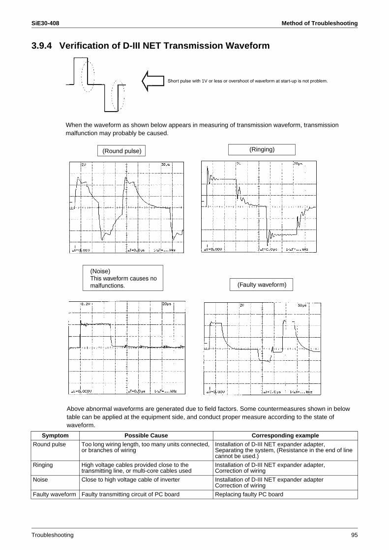
SiE30-408 Method of Troubleshooting
Troubleshooting 95
3.9.4 Verification of D-III NET Transmission Waveform
When the waveform as shown below appears in measuring of transmission waveform, transmission malfunction may probably be caused.
Above abnormal waveforms are generated due to field factors. Some countermeasures shown in below table can be applied at the equipment side, and conduct proper measure according to the state of waveform.
Symptom Possible Cause Corresponding example
Round pulse Too long wiring length, too many units connected, or branches of wiring
Installation of D-III NET expander adapter,Separating the system, (Resistance in the end of line cannot be used.)
Ringing High voltage cables provided close to the transmitting line, or multi-core cables used
Installation of D-III NET expander adapter,Correction of wiring
Noise Close to high voltage cable of inverter Installation of D-III NET expander adapterCorrection of wiring
Faulty waveform Faulty transmitting circuit of PC board Replacing faulty PC board
Short pulse with 1V or less or overshoot of waveform at start-up is not problem.
(Round pulse) (Ringing)
(Faulty waveform)
(Noise)This waveform causes no malfunctions.

Malfunction Tree Analysis (FTA) SiE30-408
96 Troubleshooting
4. Malfunction Tree Analysis (FTA)What is FTA? (Fault Tree Analysis)For analyzing a symptom, put the causes relating to the phenomenon in a dendritic figure.
For project with VRV system, general contractors and subcontractors generally enter in the supply route. As a recent trend, they often request an explanation with FTA method. (i.e., only a reasonable explanation can be accepted.)
With this method, the causes can be analyzed logically and reasonably, and causes can also be narrowed down by using a process of elimination.Moreover, in explanation or reporting, this method can make them persuasive.
Cause of symptom
Cause of symptom
Symptom
Cause A of cause
Cause B of cause
Cause C of cause
Cause D of cause
No problems were found by investigation.
No problems were found by investigation.
In the range checked, no problems were found, however, the possibility of problems still remains.
Part failure, after replacement, the stateis perfectly good.
…
…
…
…
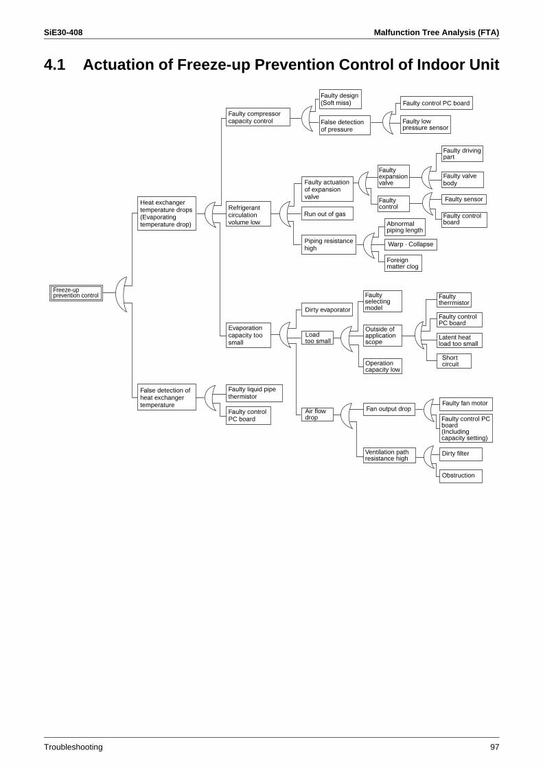
SiE30-408 Malfunction Tree Analysis (FTA)
Troubleshooting 97
4.1 Actuation of Freeze-up Prevention Control of Indoor Unit
Heat exchangertemperature drops(Evaporatingtemperature drop)
False detection of heat exchangertemperature
Faulty compressorcapacity control
Faulty design(Soft miss)
Refrigerantcirculationvolume low
Evaporationcapacity too small
Faulty liquid pipe thermistor
Faulty controlPC board
False detection of pressure
Faulty actuationof expansionvalve
Piping resistancehigh
Run out of gas
Dirty evaporator
Air flowdrop
Faulty control PC board
Faulty low pressure sensor
Faultyexpansionvalve
Faultycontrol
Abnormalpiping length
Warp · Collapse
Foreign matter clog
Faultyselectingmodel
Outside of applicationscope
Operationcapacity low
Fan output drop
Ventilation pathresistance high
Faulty driving part
Faulty sensor
Faulty control board
Faulty valve body
Faultytherrmistor
Short circuit
Faulty controlPC board
Latent heatload too small
Faulty fan motor
Faulty control PC board(Includingcapacity setting)
Dirty filter
Obstruction
Loadtoo small
Freeze-upprevention control
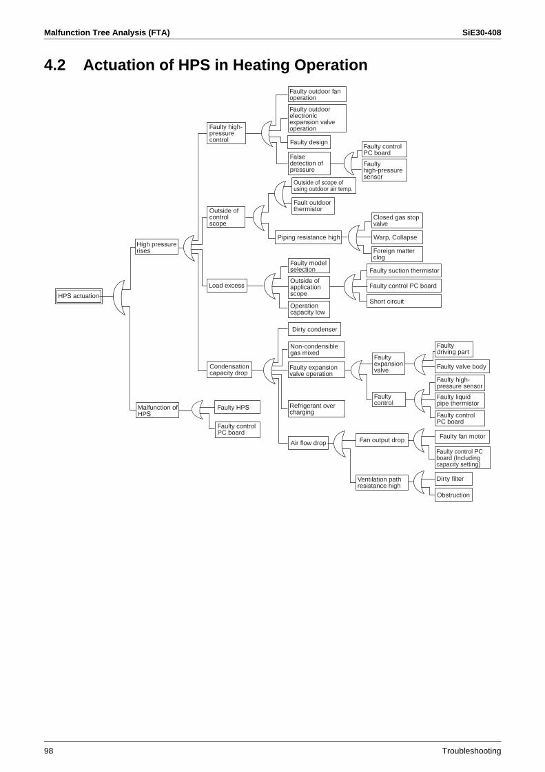
Malfunction Tree Analysis (FTA) SiE30-408
98 Troubleshooting
4.2 Actuation of HPS in Heating Operation
Short circuitHPS actuation
High pressurerises
Malfunction of HPS
Faulty high-pressurecontrol
Outside of controlscope
Load excess
Condensationcapacity drop
Faulty controlPC board
Faulty HPS
Faulty outdoor fanoperation
Faulty control PC board
Closed gas stopvalve
Foreign matterclog
Faulty outdoorelectronicexpansion valve operation
Faulty design
Falsedetection of pressure
Outside of scope of using outdoor air temp.
Fault outdoorthermistor
Piping resistance high
Faulty model selection
Outside of applicationscope
Operationcapacity low
Non-condensiblegas mixed
Dirty condenser
Faulty expansionvalve operation
Refrigerant over charging
Air flow drop
Faultyhigh-pressuresensor
Warp, Collapse
Faulty control PC board
Faulty suction thermistor
Faultyexpansionvalve
Faultycontrol
Fan output drop
Ventilation pathresistance high
Faultydriving part
Faulty valve body
Faulty high-pressure sensor
Faulty liquidpipe thermistor
Faulty control PC board
Faulty fan motor
Faulty control PC board (Includingcapacity setting)
Dirty filter
Obstruction
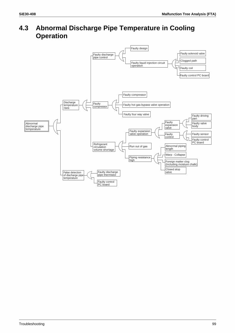
SiE30-408 Malfunction Tree Analysis (FTA)
Troubleshooting 99
4.3 Abnormal Discharge Pipe Temperature in Cooling Operation
Faulty design
Clogged path
Faulty coil
Faulty control PC board
Faulty compressor
Faulty four way valve
Warp · Collapse
Faulty sensor
Faulty hot gas bypass valve operation
Run out of gas
Abnormaldischarge pipe temperature
Dischargetemperaturerises
False detection of discharge pipe temperature
Faulty dischargepipe control
Faultycompressor
Refrigerantcirculationvolume shortage
Faulty dischargepipe thermistor
Faulty controlPC board
Faulty liquid injection circuitoperation
Faulty expansionvalve operation
Piping resistancehigh
Faulty solenoid valve
Faultyexpansionvalve
Faultycontrol
Abnormal piping length
Closed stopvalve
Foreign matter clog (Including moisture chalk)
Faulty driving part
Faulty controlPC board
Faulty valve body
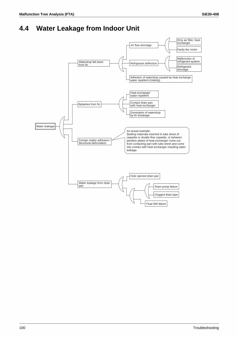
Malfunction Tree Analysis (FTA) SiE30-408
100 Troubleshooting
4.4 Water Leakage from Indoor Unit
Air flow shortage
Faulty fan motor
Refrigerant deflection
Hole opened drain pan
Drain pump failure
Clogged drain pipe
Float SW failure
Splashes from fin
An actual example;Sealing materials inserted in tube sheet of cassette or double flow cassette, or between partition plates of heat exchanger come outfrom contacting part with tube sheet and come into contact with heat exchanger resulting waterleakage.
Water leakage
Waterdrop fall down from fin
Foreign matter adhesion / Structural deformation
Water leakage from drainpan
Adhesion of waterdrop caused by heat exchangewater repellent (misting)
Heat exchangerwater repellent
Contact drain panwith heat exchanger
Generation of waterdropby fin breakage
Dirty air filter, heatexchanger
Malfunction of refrigerant system
Refrigerantshortage
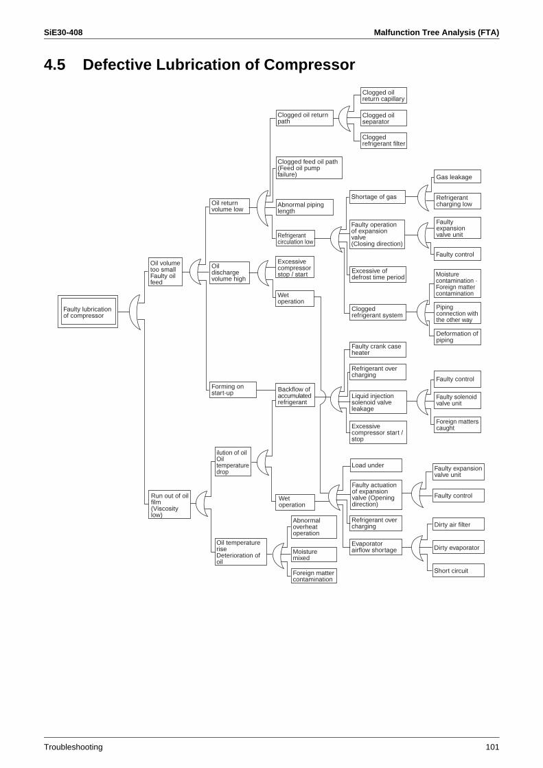
SiE30-408 Malfunction Tree Analysis (FTA)
Troubleshooting 101
4.5 Defective Lubrication of Compressor
Load under
Short circuit
Dirty evaporator
Dirty air filter
Faulty control
Gas leakage
Faulty lubricationof compressor
Oil volumetoo smallFaulty oil feed
Run out of oil film(Viscositylow)
Oil return volume low
Oildischargevolume high
Forming on start-up Backflow of
accumulatedrefrigerant
ilution of oilOiltemperaturedrop
Oil temperatureriseDeterioration of oil
Clogged oil return path
Abnormal piping length
Refrigerantcirculation low
Wet operation
Clogged feed oil path(Feed oil pumpfailure)
Excessive compressorstop / start
Abnormaloverheatoperation
Moisturemixed
Foreign mattercontamination
Clogged oil return capillary
Clogged oil separator
Refrigerantcharging low
Faultyexpansionvalve unit
Pipingconnection with the other way
Deformation of piping
Faulty solenoidvalve unit
Foreign matterscaught
Faulty expansionvalve unit
Shortage of gas
Faulty operationof expansionvalve(Closing direction)
Excessive of defrost time period
Faulty crank caseheater
Refrigerant over charging
Refrigerant over charging
Evaporatorairflow shortage
Cloggedrefrigerant system
Liquid injection solenoid valve leakage
Excessive compressor start / stop
Faulty actuationof expansionvalve (Opening direction)
Moisturecontamination · Foreign mattercontamination
Faulty control
Faulty controlWet operation
Cloggedrefrigerant filter
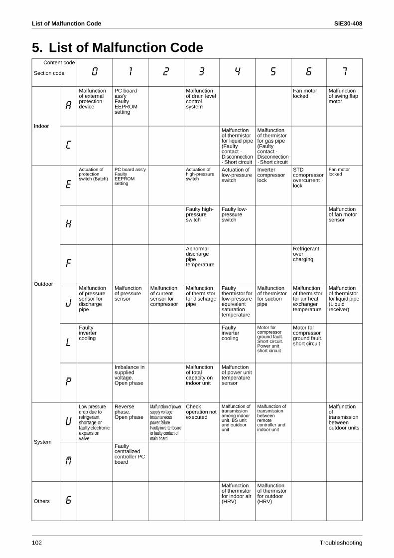
List of Malfunction Code SiE30-408
102 Troubleshooting
5. List of Malfunction CodeContent code
Section code 0 1 2 3 4 5 6 7
Indoor
A
Malfunctionof external protection device
PC board ass'yFaultyEEPROM setting
Malfunctionof drain level control system
Fan motor locked
Malfunctionof swing flap motor
C
Malfunctionof thermistor for liquid pipe(Faulty contact · Disconnection · Short circuit
Malfunction of thermistor for gas pipe(Faultycontact · Disconnection · Short circuit
Outdoor
E
Actuation of protection switch (Batch)
PC board ass'yFaulty EEPROM setting
Actuation of high-pressure switch
Actuation of low-pressureswitch
Inverter compressor lock
STDcomopressorovercurrent · lock
Fan motor locked
H
Faulty high-pressureswitch
Faulty low-pressureswitch
Malfunctionof fan motor sensor
F
Abnormal discharge pipetemperature
Refrigerantovercharging
J
Malfunctionof pressure sensor for discharge pipe
Malfunctionof pressure sensor
Malfunction of current sensor for compressor
Malfunctionof thermistor for discharge pipe
Faultythermistor for low-pressureequivalentsaturation temperature
Malfunction of thermistor for suction pipe
Malfunctionof thermistor for air heat exchanger temperature
Malfunctionof thermistor for liquid pipe (Liquidreceiver)
L
Faultyinverter cooling
Faultyinverter cooling
Motor for compressorground fault.Short circuit.Power unit short circuit
Motor for compressor ground fault. short circuit
P
Imbalance in suppliedvoltage.Open phase
Malfunctionof total capacity on indoor unit
Malfunctionof power unit temperaturesensor
System
U
Low pressure drop due to refrigerant shortage or faulty electronic expansion valve
Reverse phase.Open phase
Malfunction of power supply voltageInstantaneous power failureFaulty inverter board or faulty contact of main board
Checkoperation not executed
Malfunction of transmission among indoor unit, BS unit and outdoor unit
Malfunction of transmission between remote controller and indoor unit
Malfunctionoftransmissionbetweenoutdoor units
M
Faultycentralizedcontroller PC board
Others 6
Malfunctionof thermistor for indoor air (HRV)
Malfunction of thermistor for outdoor (HRV)

SiE30-408 List of Malfunction Code
Troubleshooting 103
8 9 A H C J E F
Malfunction of driving part of electronicexpansion valve
Malfunction of dust collecting element
Malfunction of capacity setting
Abnormal drain
Malfunction of thermistor for suction air(Faulty contact / Disconnection / Short circuit / Failure)
Malfunction of thermistor for discharge air(Faulty contact / Disconnection / Short circuit / Failure)
Malfunction of remote controllersensor
Malfunction of driving part of electronicexpansionvalve
Malfunction of compressor 1 temperaturesensor
Malfunction of thermistor for outdoor air temp.
Malfunction of sensor
Dry alert
Malfunction of compressortemperaturesensor
Malfunction of thermistor for equalizing oil pipe
Malfunction of outlet thermistor for double pipe heat exchanger
Malfunction of pressuresensor for discharge pipe
Malfunction of oil temperature thermistorsystem
Malfunction of suction pipe pressure sensor
Malfunction of thermistor for cooling heat exchanger (Secondary side)Malfunction of thermistor for sub tank
Malfunciton of oil temperature thermistor systemMalfunction of thermistor for heating heat exchange (Primary side)
Compressor overload · Motor wire cut for compressor
Compressor locked
Malfunction of power unit
Malfunction of transmissionbetweeninverter and control units
Malfunction of transmission between main unit and sub remote controller(Malfunction of sub remote controller)
Malfunction of transmissionamong indoor unit of other same system, BS unit and outdoor unit
Faultycombination among indoor unit, outdoor unit, BS unit and remote controllerFaulty setting
Faulty system Duplication of centralizedaddress
Malfunciton of transmissionbetween indoor unit and centralizedcontroller
System not set
Malfunction of transmissionbetween centralized controllers
Faultycombination of centralized controller
Faulty central remotecontrolleraddress setting
Malfunction of HRV(Dust-collecting element of HRV)
Malfunction of damper systemMalfunction of damper system + Malfunction thermistor(HRV)
Faulty door switch or relay connector(Dust collecting of HRV · Humidified unit)
Malfunction of simple remote controller

List of Malfunction Code SiE30-408
104 Troubleshooting
Malfunction Code Display by Outdoor Unit PC Board
Contents of malfunctionMalfunction
code
Abnormal discharge pressure HPS actuation E3
Abnormal suction pressure Abnormal Pe E4
Compressor lock Detection of INV compressor lock E5
OC actuation Detection of STD1 compressor lock E6
Detection of STD2 compressor lock
Outdoor unit fan motor over load · over current · Abnormal lock of outdoor unit fan motor
Instantaneous over current of DC fan motor
E7
Detection of DC fan motor lock
Malfunction of electronic expansion valve
EV1 E9
EV2
EV3
Abnormal position signal of outdoor unit fan motor
Abnormal position signal of DC fan motor
H7
Malfunction sensor for outdoor temperature
Malfunction of Ta sensor H9
Malfunction of sensor for thermal storage unit
HC
Abnormality in water system of thermal storage unit
HJ
Malfunction of transmission between thermal storage unit and controller
HF
Abnormal discharge pipe temperature
Abnormal Td F3
Abnormal heat exchanger temperature
Refrigerant over charging F6
Malfunction of current sensor Malfunction of CT1 sensor J2
Malfunction of CT2 sensor
Malfunction of sensor for discharge pipe temperature
Malfunction of Tdi sensor J3
Malfunction of Tds1 sensor
Malfunction of Tds2 sensor
Malfunction of sensor for heat exchange pipe
Malfunction of Tg1 sensor J4
Malfunction of Tg2 sensor
Malfunction of sensor for suction pipe temperature
Malfunction of Ts sensor J5
Malfunction of sensor for heat exchange temperature
Malfunction of Tb sensor J6
Malfunction of sensor for receiver temperature
Malfunction of Tl sensor J7
Malfunction of sensor for oil pressure equalizing pipe temperature
Malfunction of To sensor J8
Malfunction of sensor for subcooled heat exchanger temperature
Malfunction of Tsh sensor J9
Malfunction of sensor for discharge pressure
Malfunction of Pc sensor JA
Malfunction of sensor for suction pressure Malfunction of Pe sensor JC
Inverter radiation fin temperature rise
Over heating of inverter radiation fin temperature
L4
DC output over current Inverter instantaneous over current L5
Electronic thermal switch Electronic thermal switch 1 L8
Electronic thermal switch 2
Out-of-step
Speed down after startup
Lightening detection
Stall prevention (Limit time) Stall prevention (Current increasing) L9
Stall prevention (Faulty startup)
Abnormal waveform in startup
Out-of-step
Malfunction of transmission between inverter and outdoor unit
Malfunction of inverter transmission LC
To enter the monitor mode, press the MODE button (BS1) when in "Settingmode" 1.
Press the RETURN button (BS3) andswitches to the initial status of "Monitor mode".
<Selection of Setting Item>
Press the SET button (BS2) and setthe LED display to the setting item.
<Confirmation of malfunction 1>
Press the RETURN button (BS3)once to display "First digit" of malfunction code in LED.
<Confirmation of malfunction 2>
Press the SET button (BS2) once to display "Second digit" of malfunctioncode in LED.
<Confirmation of malfunction 3>
Press the SET button (BS2) once to display "master or slave 1 or slave 2" and "malfunction location" in LED.
* Press the MODE button (BS1) andreturns to "Setting mode 1".
Monitor mode

SiE30-408 List of Malfunction Code
Troubleshooting 105
Malfunc-tioncode
Check of malfunction 1 Check of malfunction 2 Check of malfunction 3LED1 LED2 LED3 LED4 LED5 LED6 LED7 LED1 LED2 LED3 LED4 LED5 LED6 LED7 LED1 LED2 LED3 LED4 LED5 LED6 LED7
E3 5 7 7 5 5 5 7 7 5 5 5 7 7
E4 5 7 5 7 7 5 7 7
E5 5 7 5 7 5 5 7 7
E6 5 7 5 5 7 5 7 5
5 7 5 5 7 5 5 7
E7 5 7 5 5 5 5 7 5
E9 5 5 7 7 5 5 7 5
5 5 7
5 5 5
H7 5 7 5 7 7 5 7 5 5 5 5 7 5
H9 5 5 7 7 5 5 7 7
HC 5 5 5 7 7 5 7 7
HJ 5 5 5 7 5 5 7 7
HF 5 5 5 5 5 5 7 7
F3 5 7 5 7 5 5 7 7 5 5 5 7 7
F6 5 7 5 5 7 5 7 7
J2 5 7 5 5 7 5 7 7 5 7 5 7 5
5 5 7
J3 5 7 7 5 5 5 7 5
5 5 7
5 5 5
J4 5 7 5 7 7 5 7 5
5 7
J5 5 7 5 7 5 5 7 7
J6 5 7 5 5 7 5 7 7
J7 5 7 5 5 5 5 7 7
J8 5 5 7 7 7 5 7 7
J9 5 5 7 7 5 5 7 7
JA 5 5 7 5 7 5 7 7
JC 5 5 5 7 7 5 7 7
L4 5 7 5 5 5 5 7 5 7 7 5 7 7
L5 5 7 5 7 5 5 7 7
L8 5 5 7 7 7 5 7 7
L9 5 5 7 7 5 5 7 7
LC 5 5 5 7 7 5 7 7

List of Malfunction Code SiE30-408
106 Troubleshooting
Contents of malfunction Malfunction code
Open phase / Power supply imbalance
Imbalance of inverter power supply voltage
P1
Malfunction of temperature sensor inside switch box
Malfunction of thermistor for inverter box
P3
Malfunction of sensor for inverter radiation fin temperature
Malfunction of thermistor for inverter fin
P4
Faulty combination of inverter and fan driver
Incorrect combination of inverter and fan driver
PJ
Shortage of refrigerant Shortage of refrigerant alert U0
Reverse phase Malfunction of reverse phase U1
Abnormal power supply voltage Inverter voltage shortage U2
Inverter open phase (phase T)
Malfunction of charging for capacitor in inverter main circuit
Check operation not executed U3
Faulty transmission between indoor units and outdoor units
Malfunction of I / O transmission U4
Faulty transmission between outdoor units, faulty transmission between thermal storage units, duplication of CT address
Malfunction of O / O transmission U7
Faulty transmission of other system Indoor unit system malfunction in other system or other unit of own system
U9
Faulty field setting Abnormal connection with excessive number of indoor units
UA
Conflict of refrigerant type in indoor units
Faulty system function Incorrect wiring (Auto address malfunction)
UH
Faulty transmission in accessory devices, conflict in wiring and piping, no setting for system
Malfunction of multi level converter, abnormality in conflict check
UJ
UF
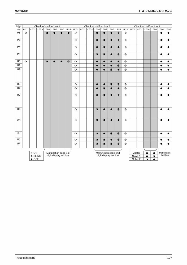
SiE30-408 List of Malfunction Code
Troubleshooting 107
Malfunc-tioncode
Check of malfunction 1 Check of malfunction 2 Check of malfunction 3LED1 LED2 LED3 LED4 LED5 LED6 LED7 LED1 LED2 LED3 LED4 LED5 LED6 LED7 LED1 LED2 LED3 LED4 LED5 LED6 LED7
P1 5 5 7 7 7 5 7 7 7 5 5 7 7
P3 5 7 7 5 5 5 7 7
P4 5 7 5 7 7 5 7 7
PJ 5 5 5 7 5 5 7 7
U0 5 5 7 7 5 5 7 7 7 7 5 7 7
U1 5 7 7 7 5 5 7 7
U2 5 7 7 5 7 5 7 7
U3 5 7 7 5 5 5 7 7
U4 5 7 5 7 7 5 7 7
U7 5 7 5 5 5 5 7 7
U9 5 5 7 7 5 5 7 7
UA 5 5 7 5 7 5 7 7
UH 5 5 7 5 5 5 7 7
UJ 5 5 5 7 5 5 7 7
UF 5 5 5 5 5 5 7 7
4:ON Malfunction code 1st digit display section
Malfunction code 2nd digit display section
Master 7 7 Malfunction location5:BLINK Slave 1 7 5
7:OFF Salve 2 5 7

Operating Condition Check Sheet SiE30-408
108 Troubleshooting
6. Operating Condition Check SheetContent of malfunction:Service shop: Person in charge:
* Check on MV opening degree by using checker or remote controller with special setting.
Model name Serial No. System name, Installation site
Outdoor unit
Indoor unit
No. of unit connectedunit(s)
Capacity%
No.1
No.2
No.3
No.4
No.5
No.6
No.7
No.8
Pipe length / Height difference m/ m Frequency of malfunction generated / time(s)
Time zone malfunction generated About o'clock Malfunction code
Check item Inspection method Standard
Measured valueCheck
No.1 No.2 No.3 No.4 No.5 No.6 No.7 No.8
Indoordata
Suctiontemperature
With remote controller No. 41
Dischargetemperature With thermometer
Liquid pipe temperature
With remote controller No. 41
Gas pipe temperature
With remote controller No. 41
Preset flow rate With remote controller
MV opening degree
*
Inspection item Inspection method Reference Measured value Check
Outdoorunitoperation data
Power supply voltage
Measure voltage between each phase with tester (in operation)
Within ± 10 % of rated voltageNo voltage drop
R-S VS-T VT-R V
Compressor operation capacity
Measure with clamp meter
—
INVHz
STD1ON / OFF
STD2ON / OFF
High pressure Measure with pressure gauge, service checker(After 20 minutes or later from operation start) — MPa
Low pressure Measure with pressure gauge, service checker(After 20 minutes or later from operation start) — MPa
Liquid pressure Measure with pressure gauge(After 20 minutes or later from operation start) — MPa
Outdoor air temperature
Measure with thermometer(Measure in the place receiving no influence of discharged air from outdoor unit)
In cooling; -5 to 43°CIn heating; -15 to 16°C
°C
Suction / discharge air temperature
Measure with thermometer (Check on short circuiting)(Measure the maximum different temperature with outdoor.)
—
Suction°C
Discharge°C
Discharge pipe temperature
Measure with surface thermometer or service checker
(Tc + 20) to 120°CTc: Saturation temperature equivalent to high pressure
INV °C
STD1 °C
STD2 °C
Suction pipe temperature
Measure with surface thermometer or service checker(Measure in the place receiving no influence of injection)
Te + (2 to 20)°CTe: Saturation temperature equivalent to low pressure °C
Others“Complains or requests from users, Operation conditions at the time of measuring (No. of thermostat ON units, etc.), Past record of malfunction, remedies executed, Comments, etc.”
SiE30-408
Cases for Examination 109
1. VRV in General ...................................................................................1102. Indoor Unit Related Examples ............................................................1213. Malfunction of Transmission Examples...............................................123

VRV in General SiE30-408
110 Cases for Examination
1. VRV in General1.1 Malfunction "E3" is Displayed in Cooling Operation.
Applicable Models
VRV Plus series (L unit)
Condition Though an malfunction "E3 (abnormal high-pressure)" is sometimes displayed on the VRV Plus series (L unit) system, the same condition is not reproduced at the time of inspection (unintentional operation).
Cause Electronic expansion valve of the STD outdoor unit 2, which must be opened fully during cooling operation, is malfunctioning. Since the valve is not opened, pressure for high-pressure use has exceeded and accutuated the high-pressure switch.
Measure Recovers by replacing the electronic expansion valve drive coil of the STD outdoor unit 2.
Point of Diagnosis
When examining multiple outdoor units, do not inspect only the inverter outdoor units but inspect STD outdoor units 1 and 2.
1.2 Malfunction "F6" is Displayed during Check Operation in the Winter Season.
Applicable Models
RX(Y)(Q) ~ M (VRV II series)
Condition A malfunction "F6" (overcharge of refrigerant) is displayed when a "check operation" is executed as a test operation under the condition of low outdoor temperature in the winter season.
Cause Due to temporary refrigerant mixing into refrigerating oil, misjudgment is made when a "check operation" is executed under the condition of low outdoor temperature.
Measure The condition completes by executing the "check operation" again.
Point of Diagnosis
Be sure to execute a "check operation" with the front panel closed. Or, misjudgment is made even if the outdoor temperature is low.
Conditions Possible misjudgment
Low outdoor temperature F6
High outdoor humidity E3, E4. UF
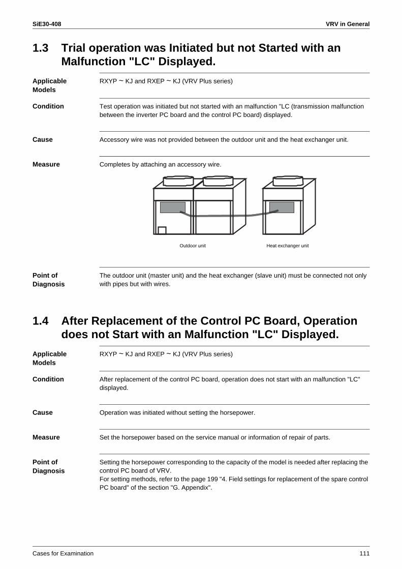
SiE30-408 VRV in General
Cases for Examination 111
1.3 Trial operation was Initiated but not Started with an Malfunction "LC" Displayed.
Applicable Models
RXYP ~ KJ and RXEP ~ KJ (VRV Plus series)
Condition Test operation was initiated but not started with an malfunction "LC (transmission malfunction between the inverter PC board and the control PC board) displayed.
Cause Accessory wire was not provided between the outdoor unit and the heat exchanger unit.
Measure Completes by attaching an accessory wire.
Point of Diagnosis
The outdoor unit (master unit) and the heat exchanger (slave unit) must be connected not only with pipes but with wires.
1.4 After Replacement of the Control PC Board, Operation does not Start with an Malfunction "LC" Displayed.
Applicable Models
RXYP ~ KJ and RXEP ~ KJ (VRV Plus series)
Condition After replacement of the control PC board, operation does not start with an malfunction "LC" displayed.
Cause Operation was initiated without setting the horsepower.
Measure Set the horsepower based on the service manual or information of repair of parts.
Point of Diagnosis
Setting the horsepower corresponding to the capacity of the model is needed after replacing the control PC board of VRV.For setting methods, refer to the page 199 "4. Field settings for replacement of the spare control PC board" of the section "G. Appendix".
Outdoor unit Heat exchanger unit
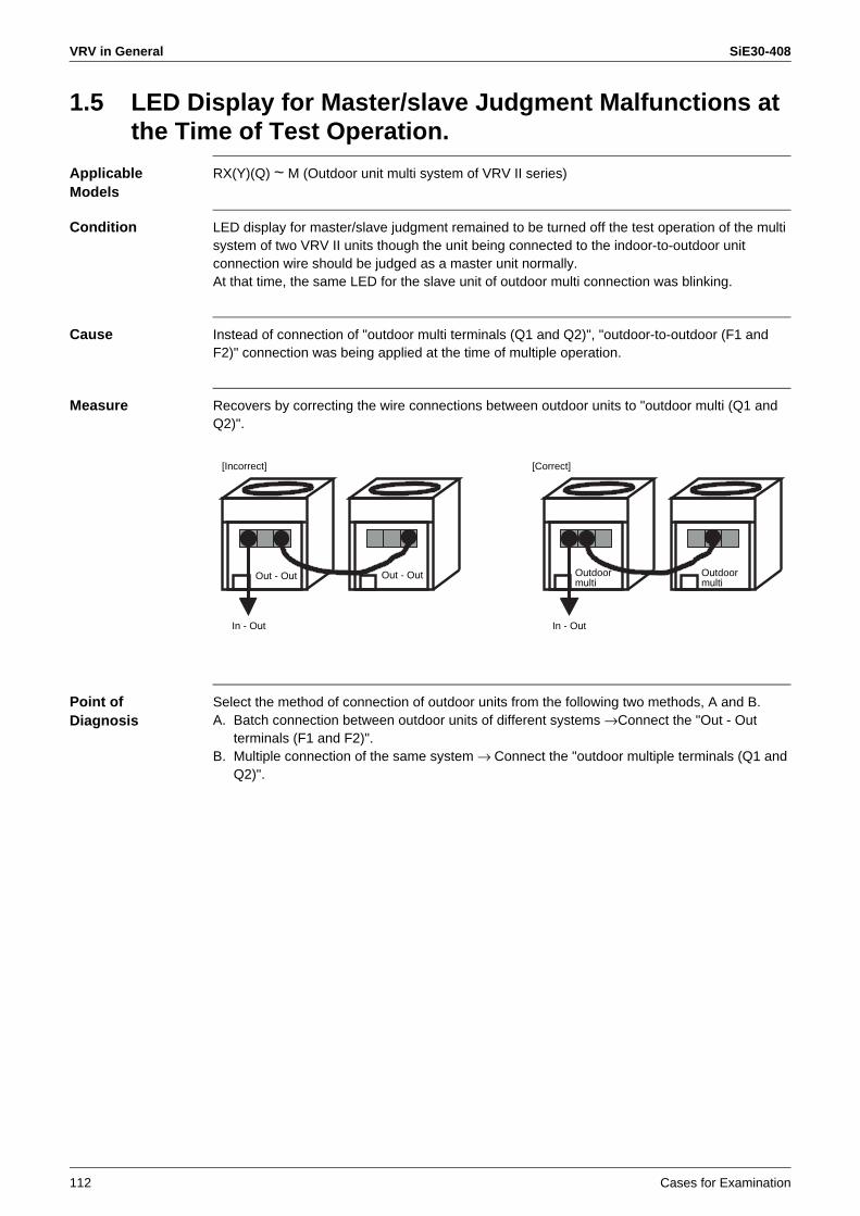
VRV in General SiE30-408
112 Cases for Examination
1.5 LED Display for Master/slave Judgment Malfunctions at the Time of Test Operation.
Applicable Models
RX(Y)(Q) ~ M (Outdoor unit multi system of VRV II series)
Condition LED display for master/slave judgment remained to be turned off the test operation of the multi system of two VRV II units though the unit being connected to the indoor-to-outdoor unit connection wire should be judged as a master unit normally.At that time, the same LED for the slave unit of outdoor multi connection was blinking.
Cause Instead of connection of "outdoor multi terminals (Q1 and Q2)", "outdoor-to-outdoor (F1 and F2)" connection was being applied at the time of multiple operation.
Measure Recovers by correcting the wire connections between outdoor units to "outdoor multi (Q1 and Q2)".
Point of Diagnosis
Select the method of connection of outdoor units from the following two methods, A and B.A. Batch connection between outdoor units of different systems →Connect the "Out - Out
terminals (F1 and F2)".B. Multiple connection of the same system → Connect the "outdoor multiple terminals (Q1 and
Q2)".
In - Out
Out - Out Out - Out
In - Out
[Incorrect] [Correct]
Outdoormulti
Outdoormulti

SiE30-408 VRV in General
Cases for Examination 113
1.6 Cautions for Test Operation
Applicable Models
RX(Y)(Q) ~ M (VRV II series)
Condition Though a test operation (check operation) in combination with the VRV II series outdoor unit had completed, an malfunction "E4 (abnormal low pressure malfunction)" or an malfunction "F3 (abnormal discharge pipe temperature malfunction )" occurred frequently after that.
Cause Due to erroneous connection of wires and pipes, electronic expansion valve of the indoor unit does not open when only a single system is operated, which causes a faulty refrigerant circulation and results in a drop of pressure for low-pressure. Normal pressure is obtained by operating two systems simultaneously.
Measure Issue a slip of request for modification work so that the erroneous connection of wires and pipes is corrected.
Point of Diagnosis
If a test operation (check operation) of multiple units of VRV II series is executed simultaneously, the test operation ends normally even if an erroneous connection exists. Be sure to execute a test operation (check operation) on an individual unit.Check whether there is an erroneous connection if an malfunction "E4" or an malfunction "F3" generates on the existing equipment.
1.7 Cautions for Demand Control with Externally Controlled Adapter
Applicable Models
RX(Y)(Q) ~ M (VRV II series)
Condition Demand control with an externally controll adapter attached to the VRV II series outdoor unit is desired.Thermostat does not turn off though C and 3 were short-circuited i.e., demand level 3, after setting.* Set items: Demand address 1 (Setting mode 2-2)
Externally controll ADP address 1Demand setting change to ON from OFF (Setting mode 2-12)
Cause Demand level setting (setting mode 2-30) remained to be the factory set value i.e., "70%". It should be changed the setting to "60%" to turn OFF the thermostat by the short circuit between C and 3.
Measure The thermostat turns OFF by changing the setting mode 2-30 to "60%".
Point of Diagnosis
Change of mode setting is needed in accordance with the purpose of use.For setting methods, refer to the page 56 "2. Field setting on outdoor unit", of the section "C. Filed Settings from remote controller."
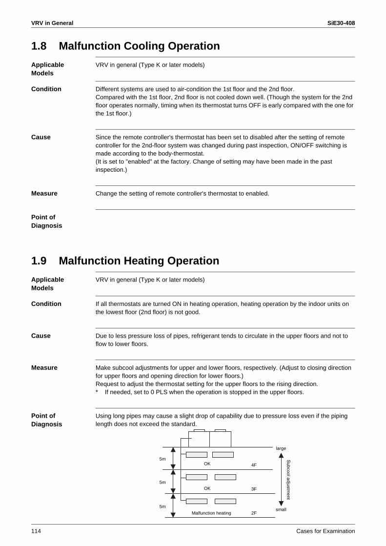
VRV in General SiE30-408
114 Cases for Examination
1.8 Malfunction Cooling Operation
Applicable Models
VRV in general (Type K or later models)
Condition Different systems are used to air-condition the 1st floor and the 2nd floor.Compared with the 1st floor, 2nd floor is not cooled down well. (Though the system for the 2nd floor operates normally, timing when its thermostat turns OFF is early compared with the one for the 1st floor.)
Cause Since the remote controller's thermostat has been set to disabled after the setting of remote controller for the 2nd-floor system was changed during past inspection, ON/OFF switching is made according to the body-thermostat.(It is set to "enabled" at the factory. Change of setting may have been made in the past inspection.)
Measure Change the setting of remote controller's thermostat to enabled.
Point of Diagnosis
1.9 Malfunction Heating Operation
Applicable Models
VRV in general (Type K or later models)
Condition If all thermostats are turned ON in heating operation, heating operation by the indoor units on the lowest floor (2nd floor) is not good.
Cause Due to less pressure loss of pipes, refrigerant tends to circulate in the upper floors and not to flow to lower floors.
Measure Make subcool adjustments for upper and lower floors, respectively. (Adjust to closing direction for upper floors and opening direction for lower floors.)Request to adjust the thermostat setting for the upper floors to the rising direction.* If needed, set to 0 PLS when the operation is stopped in the upper floors.
Point of Diagnosis
Using long pipes may cause a slight drop of capability due to pressure loss even if the piping length does not exceed the standard.
5m
5m
5m
OK
OK
Malfunction heating
4F
3F
2Fsmall
large
Subcooladjustm
ent
SiE30-408 VRV in General
Cases for Examination 115
1.10 Inferior Insulation of the Compressor before Test Operation
Applicable Models
VRV in general
Condition At the time of test operation, compressor was replaced since the insulation was found insufficient in the insulation measurement with the power not supplied.
Cause Insulation at the terminal section inside the compressor dropped temporarily due to non-operational condition of liquid refrigerant accumulated inside the compressor.
Measure Resolved by supplying power to the crank case heater for 6 hours.
Point of Diagnosis
Measure the insulation resistance of the compressor after supplying power to the crank case heater for 6 hours.
1.11 No Heating Operation is Available though Cooling Operation is Possible. (Fan only Operation Continues with no Malfunction Displayed.)
Applicable Models
VRV in general
Condition Compressor for one of two systems failed three times. Noise is heard on the compressor another system.
Cause Erroneous connection of wires and pipes.
Measure Recovers by correcting the connection.
Point of Diagnosis
1. Operate a single indoor unit and check whether cold or hot air is obtained.2. Operate also an another indoor unit. Then stop the 1st unit and check whether cold or hot
blast is obtained.3. Check the remaining units according to the above steps.
Note: Please note that, if an operation of another unit is initiated after stopping the 1st unit, the outdoor unit does not start for a while due to restart protection control.
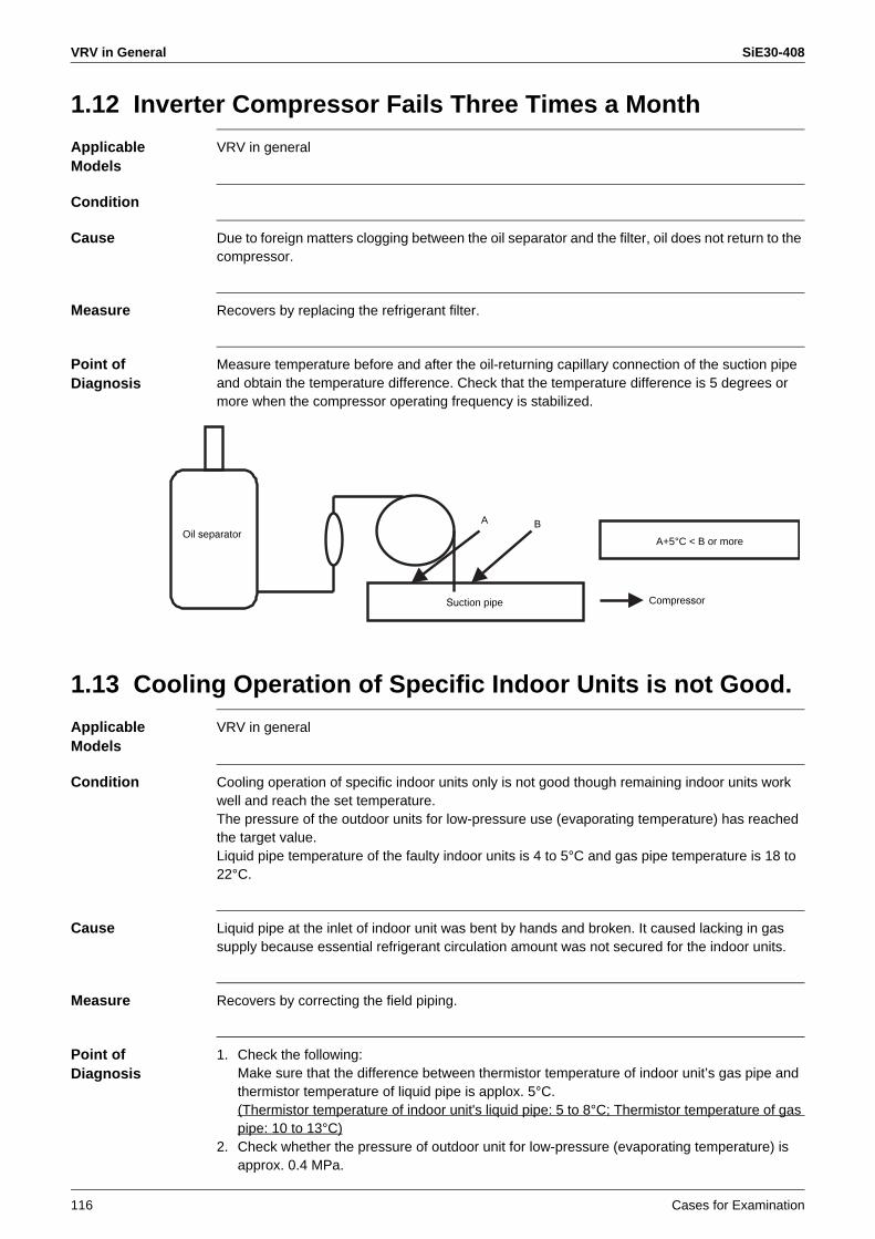
VRV in General SiE30-408
116 Cases for Examination
1.12 Inverter Compressor Fails Three Times a Month
Applicable Models
VRV in general
Condition
Cause Due to foreign matters clogging between the oil separator and the filter, oil does not return to the compressor.
Measure Recovers by replacing the refrigerant filter.
Point of Diagnosis
Measure temperature before and after the oil-returning capillary connection of the suction pipe and obtain the temperature difference. Check that the temperature difference is 5 degrees or more when the compressor operating frequency is stabilized.
1.13 Cooling Operation of Specific Indoor Units is not Good.
Applicable Models
VRV in general
Condition Cooling operation of specific indoor units only is not good though remaining indoor units work well and reach the set temperature.The pressure of the outdoor units for low-pressure use (evaporating temperature) has reached the target value.Liquid pipe temperature of the faulty indoor units is 4 to 5°C and gas pipe temperature is 18 to 22°C.
Cause Liquid pipe at the inlet of indoor unit was bent by hands and broken. It caused lacking in gas supply because essential refrigerant circulation amount was not secured for the indoor units.
Measure Recovers by correcting the field piping.
Point of Diagnosis
1. Check the following:Make sure that the difference between thermistor temperature of indoor unit’s gas pipe and thermistor temperature of liquid pipe is applox. 5°C.(Thermistor temperature of indoor unit's liquid pipe: 5 to 8°C; Thermistor temperature of gas pipe: 10 to 13°C)
2. Check whether the pressure of outdoor unit for low-pressure (evaporating temperature) is approx. 0.4 MPa.
Oil separator
Suction pipe
A B
Compressor
A+5°C < B or more

SiE30-408 VRV in General
Cases for Examination 117
1.14 Malfunction Heating Due to Overcharge of Refrigerant
Applicable Models
VRV in general
Condition Inverter compressor only operates at low frequency. Discharge temperature of the indoor units is 25°C or less and thermistor temperature of the liquid pipe is approx. 30°C when it is monitored through the service mode of the indoor remote controller. The low-pressure at that time is around 0.2MPa.
Cause Overcharged refrigerant.Due to overcharge, refrigerant accumulates in the indoor unit. Under this condition, temperature of the heat exchanger itself drops though the high-pressure rises. In addition, rise of high-pressure causes rise of liquid pressure that results in minimum opening of the electronic expansion valve of outdoor units leading to the wet operation.(The low-pressure at that time comes to be 0.2MPa due to minimum EV opening.)
Measure Recovers by correcting the refrigerant to the specified amount.
Point of Diagnosis
1. Use a manifold gauge to measure the high-pressure side of the outdoor unit and the pressure of service port of the liquid-side stop valve. Then check that the difference between the pressure on the high-pressure side and the pressure of the liquid pipe (intermediate pressure) is approx. 0.2MPa or more.(Approx. 0.2-MPa differential pressure is required to secure the flow rate at the electronic expansion valve.)
2. Check whether the subcooling of each indoor unit is normal.Difference between the saturation temperature being equivalent to the high-pressure and the thermistor temperature of liquid pipe of each indoor unit is approx. 5 to 8°C(Liquid pipe temperature is normally approx. 38°C or higher.)
VRV in General SiE30-408
118 Cases for Examination
1.15 Inverter Compressor Fails in a Short Period.
Applicable Models
VRV in general
Condition Inverter compressor for the specific outdoor unit fails due to faulty insulation.Since seizure has occurred on the metal sliding section and remaining amount of refrigerant oil is proper, in terms of malfunction mode the failure has occurred by the refrigerant oil that was diluted through wet operation.
Cause Detecting temperature of the gas pipe thermistor of outside air processing unit was 106°C being different from the specified resistance. It caused to fully open the electronic expansion valve mounted to the indoor unit and resulted in backflow of liquid.(Indoor units of VRV set to stop operation after completion of the day's work, however, the outside air processing unit set to operate around the clock.)
Measure Recovers by replacing the EV drive section of the outside air processing unit.
Point of Diagnosis
1. Use a service checker type III and check whether the superheated degree control of the indoor unit is normal.
2. If the above checker is not available, use a remote controller to check.(When replacing the compressor, locate the cause of fault of the compressor.)
1.16 Heating Operation of All Indoor Units is Faulty.
Applicable Models
VRV in general
Condition Heating operation of all indoor units is faulty though the operating capacity of indoor units is small and all units are operating.However, high-pressure of the outdoor units has reached the target value of 1.7MPa and stabilized.Temperature of liquid pipe and the one of gas pipe of indoor units are equivalent to indoor temperature.
Cause High-pressure gas flowed into the receiver due to leakage of the check valve in the receiver gas releasing circuit. It caused the rise of liquid pressure and eliminated the differential pressure from the high-pressure. Consequently the liquid accumulated due to improper amount of circulating refrigerant at the electronic expansion valve of indoor unit and drop in discharge air temperature occurred.
Measure Recovers by replacing the corresponding check valve.
Point of Diagnosis
SiE30-408 VRV in General
Cases for Examination 119
1.17 Faulty Heating.
Applicable Models
VRV in general
Condition During heating operation with the ceiling mounted built-in type indoor units, cold air was blasted sometimes causing draft. High-pressure had reached the target value and was stabilized, the discharge air temperature of indoor unit was approx. 40°C, and same condition was not reproduced during inspection of the unit.
Cause Drop of temperature in discharge air due to indoor unit's capacity control. (Temperature set by the remote controller was as low as 22°C.)In order to prevent hunting of indoor temperature due to ON/OFF switching of thermostat, VRV uses an electronic expansion valve mounted to the indoor unit to control the flow rate (capacity control) of refrigerant. In heating operation, if the temperature of suction air of indoor unit closes to the temperature set by the remote controller, capacity (flow rate of refrigerant) is adjusted by closing the opening degree of the electronic expansion valve. Therefore, if the temperature of liquid pipe of indoor unit drops and subcooling degree increases, the temperature of blow-out air drops simultaneously.
Measure Explain that it results under the normal control.
Point of Diagnosis
1. Check whether the condensation temperature (high-pressure) has reached the value around the target value of 1.7MPa during the heating operation.
2. Check whether the capacity of indoor unit is not being controlled (the difference between the temperature of suction air and set value).
VRV in General SiE30-408
120 Cases for Examination
1.18 Outdoor Unit of the Cooling Only Model Operates with Heating Operation Displayed.
Applicable Models
VRV in general
Condition Outdoor unit started operation when operation is initiated with the heating operation displayed in the local remote controller.In addition, since the corresponding unit had an optionally installed hot water coil, the coil froze and burst.
Cause Erroneous connection of cooling / heating select circuit of remote controller (connected between A and C instead of B and C).The outdoor unit has a single cooling circuit basically. Therefore, even if heating operation is displayed in the remote controller, no switching of the refrigerant circuit is made and the outdoor unit starts cooling cycle with heating operation displayed.(If a cooling / heating select remote controller is attached, priority is given to the outdoor unit.)As a result, liquid refrigerant flows into the indoor side and remaining water in the hot water coil freezes with the pump stopped.
Measure Recovers by correcting the wiring of the cooling / heating select remote controller.If a heating operation is displayed in the cooling only model, confirm the terminal connection section of the cooling / heating select remote controller of the outdoor unit.
Point of Diagnosis
1.19 High-pressure Shutdown Occurs only When the STD Compressor Starts.
Applicable Models
VRV in general
Condition High-pressure rises abnormally and the high-pressure shutdown results when the STD compressor starts during cooling operation.(High-pressure tends to be higher even in the operation of inverter compressor only.)Temperature of heat exchanger thermistor of outdoor unit was found being equivalent to the outdoor temperature when data was collected by using the service checker type III.
Cause liquid-side stop valve was not fully open.(The staff considered it was fully open when inspected.)
Measure Recovers by fully opening the stop valve.
Point of Diagnosis
Check whether the detecting temperature of heat exchanger thermistor is close to the saturation temperature being equivalent to the high-pressure.[Be sure to check all basic items like liquid-side stop valve and electronic expansion valve.]

SiE30-408 Indoor Unit Related Examples
Cases for Examination 121
2. Indoor Unit Related Examples2.1 Temperature is not Displayed on the Central Controller.
Applicable Models
FXMQ125MF + controller
Condition Though the FXYMP140MF (outside air processing unit) was built in the control range of the centralized controller, no temperature is displayed on the centralized controller. Temperature is displayed on the remote controller.
Cause Since the outside air processing air conditioner is controlled based on the discharge air, set temperature of the discharge air is displayed on the remote controller. (Type M or later models)Therefore, temperature is not displayed on the centralized controller due to the difference in meaning of set temperature compared with the normal indoor units.
Measure Explain that the contents of display are normal.
Point of Diagnosis
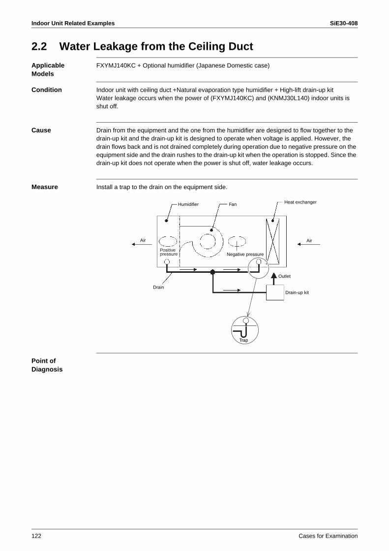
Indoor Unit Related Examples SiE30-408
122 Cases for Examination
2.2 Water Leakage from the Ceiling Duct
Applicable Models
FXYMJ140KC + Optional humidifier (Japanese Domestic case)
Condition Indoor unit with ceiling duct +Natural evaporation type humidifier + High-lift drain-up kitWater leakage occurs when the power of (FXYMJ140KC) and (KNMJ30L140) indoor units is shut off.
Cause Drain from the equipment and the one from the humidifier are designed to flow together to the drain-up kit and the drain-up kit is designed to operate when voltage is applied. However, the drain flows back and is not drained completely during operation due to negative pressure on the equipment side and the drain rushes to the drain-up kit when the operation is stopped. Since the drain-up kit does not operate when the power is shut off, water leakage occurs.
Measure Install a trap to the drain on the equipment side.
Point of Diagnosis
Humidifier Fan Heat exchanger
AirAir
Outlet
Trap
Drain-up kitDrain
Negative pressurePositive pressure

SiE30-408 Malfunction of Transmission Examples
Cases for Examination 123
3. Malfunction of Transmission Examples3.1 [Malfunction of Transmission Examples]
Display of Malfunction of Transmission due to the Elevator's Power Line
Applicable Models
VRV in general
Condition A malfunction "UE" is issued at random. It continues to be generated maximum 30 seconds.Transmitted waveforms were checked to be distorted for a period of approx. 10 seconds on site.
Cause Out-Out transmission line had been laid next to the high-voltage line of the elevator.
Measure Request to correct wiring.
Point of Diagnosis
3.2 [Malfunction of Transmission Examples] Malfunction of Transmission due to Wiring next to the High-voltage Line for Indoor Unit
Applicable Models
VRV in general
Condition A malfunction "U4" sometimes occurred on the specific system. Its cause was not located though the transmission waveforms on the outdoor unit side were checked.
Cause Waveforms on the indoor unit side were checked. The wiring on the indoor unit side had been laid next to the high-voltage line.
Measure Keep the wiring of indoor unit away from the high voltage line.
Point of Diagnosis

Malfunction of Transmission Examples SiE30-408
124 Cases for Examination
3.3 [Malfunction of Transmission Examples] Faulty Condition to Multi-core Wire
Applicable Models
VRV in general
Condition
Cause According to the wiring company, two-core lines were to be used as transmission line. However, multi-core lines are used actually. There was also a case where two cores out of four cores were being used for power supply.
Measure Request to correct the wiring.
Point of Diagnosis
3.4 [Malfunction of Transmission Examples] Faulty Condition Caused by the Use of Single-core Line
Applicable Models
VRV in general
Condition
Cause A malfunction "U4" is issued due to a single-core line used as a transmission line.
Measure Changed to the VTCF two-core line.
Point of Diagnosis

SiE30-408 Malfunction of Transmission Examples
Cases for Examination 125
3.5 [Malfunction of Transmission Examples] "Under Centralized Control" is Displayed on the Individual Remote Controller.
Applicable Models
VRV in general
Condition "Under central control" is displayed on the individual remote controller and operation by the remote controller is disabled.
Cause T1 and T2 terminals on the indoor side had been short-circuited by mistake.
Measure The short circuit line was removed. Before taking measures, check the condition because the forced stop input may have been wired intentionally based on the facility conditions on site.
Point of Diagnosis
3.6 [Malfunction of Transmission Examples] An Malfunction "U4" is Issued.
Applicable Models
VRV in general
Condition
Cause DIII-NET adapter was installed on the indoor-to-outdoor line.An malfunction "U4" is displayed on the individual remote controller though operation through the centralized controller is possible.
Measure Corrected so that the DIII-NET expander adapters installed on the outdoor-to-outdoor line.
Point of Diagnosis
Malfunction of Transmission Examples SiE30-408
126 Cases for Examination
3.7 [Malfunction of Transmission Examples] A Malfunction "UE" is Sometimes Issued.
Applicable Models
Heat recovery VRV system
Condition
Cause One BS unit in the system was oscillating.
Measure Completed by mounting a DIII-NET expander adapter.
Point of Diagnosis
3.8 [Malfunction of Transmission Examples] Faulty Condition Caused by Branch Lines.
Applicable Models
VRV in general
Condition A transmission malfunction occurred when the centralized controller was added to the existing system.
Cause Ten of all indoor-to-outdoor lines were branch lines from a single bus cable.
Measure Corrected IN - OUT wiring to one - after another wiring
Point of Diagnosis

SiE30-408
Service Checker Type3 Application Edition 127
1. List of Applicable Models of TYPE3 ....................................................1281.1 VRV Multi Systems (R410A/R407C/R22) ............................................128
2. What Service Checker Can Do ...........................................................1303. Recording and Playback of Operation Data........................................137
3.1 Menu Window (Map Mode) ..................................................................1373.2 Periodical Recording Setting Window ..................................................1393.3 Centralized Operation (F7)...................................................................1423.4 Display of Operation Data ....................................................................1423.5 Playback of Data Recorded..................................................................144
4. Collection and Playback of Data on Checker......................................1464.1 Retrieval of Raw Data ..........................................................................1474.2 Retrieval of Processed Data.................................................................1494.3 Data Processing ...................................................................................1514.4 Organizing Graph .................................................................................1684.5 Using Secondary Axis ..........................................................................1704.6 Traverse of X Axis ................................................................................172
5. Points of Analysis................................................................................1785.1 Method of Use by Symptom .................................................................1785.2 To Conduct Analysis ............................................................................1785.3 Effective Use of Checker......................................................................1805.4 Example of Checker Connection..........................................................1815.5 Method of Mounting Sensor Kit ............................................................1825.6 Place to Save Data...............................................................................183
This Edition provides a summary of collecting operation data and further processing and making effective use of excel data after the collection.For the detailed handling methods such as the operation of SERVICE CHECKER TYPE3, refer to information in the Instruction Manual.
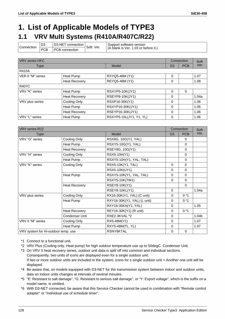
List of Applicable Models of TYPE3 SiE30-408
128 Service Checker Type3 Application Edition
1. List of Applicable Models of TYPE31.1 VRV Multi Systems (R410A/R407C/R22)
*1 Connect to a functional unit.*2 VRV Plus (Cooling only, Heat pump) for high outdoor temperature use up to 50degC. Condenser Unit.*3 On VRV II heat recovery series, outdoor unit data is split off into common and individual sections.
Consequently, two units of icons are displayed even for a single outdoor unit.If two or more outdoor units are included in the system, icons for s single outdoor unit + Another one unit will be displayed.
*4 Be aware that, on models equipped with D3-NET for the transmission system between indoor and outdoor units, data on indoor units changes at intervals of several minutes.
*5 “E: Resistant to salt damage”, “G: Resistant to serious salt damage”, or “Y: Export voltage”, which is the suffix on a model name, is omitted.
*6 With D3-NET connected, be aware that this Service Checker cannot be used in combination with “Remote control adapter” or “Individual use of schedule timer”.
ConnectionD3 D3-NET connection
Soft. Ver.Support software version(A blank is Ver. 1.03 or before it.)PCB PCB connection
VRV series-HFC Connection Soft.Ver.Type Model D3 PCB
R410A
VER II “M” series Heat Pump RXYQ5-48M (Y1) 0 1.07
Heat Recovery REYQ5-48M (Y1) 0 1.08
R407C
VRV “K” series Heat Pump RSXYP5-10K(JY1) 0 0
Heat Recovery RSEYP8-10K(JY1) 0 1.04a
VRV plus series Cooling Only RSXP16-30K(Y1) 0 1.06
Heat Pump RSXYP16-30K(JY1) 0 1.05
Heat Recovery RSEYP16-30K(JY1) 0 1.06
VRV “L” series Heat Pump RSXYP5-10L(JY1, Y1, YL) 0 1.06
VRV series-R22 Connection Soft.Ver.Type Model D3 PCB
VRV “G” series Cooling Only RSX8G, 10G(Y1, YAL) 0
Heat Pump RSXY5-10G(Y1, YAL) 0
Heat Recovery RSEY8G, 10G(Y1) 0
VRV “H” series Cooling Only RSX5-10H(Y1) 0
Heat Pump RSXY5-10H(Y1, YAL, TAL) 0
VRV “K” series Cooling Only RSX5-10K(Y1, TAL) 0 0
RSX5-10K(UY1) 0 0
Heat Pump RSXY5-10K(Y1, YAL, TAL) 0 0
RSXY5-10K(7W1) 0 0
Heat Recovery RSEY8-10K(Y1) 0
RSEY8-10KL(Y1) 0 1.04a
VRV plus series Cooling Only RX16-30K(Y1, YAL) (C unit) 0 0 *1
Heat Pump RXY16-30K(Y1, YAL) (L unit) 0 0 *1
RXY16-30KA(Y1, YAL) 0 1.05
Heat Recovery REY16-30K(Y1) (R unit) 0 0 *1
Condenser Unit RXE2-3KVAL *2 0 1.04b
VRV II “M” series Cooling Only RX5-48M(Y1) 0 1.07
Heat Pump RXY5-48M(TL, YL) 0 1.07
VRV system for Hi-outdoor temp. use RSNY8KTAL 0 0
SiE30-408 List of Applicable Models of TYPE3
Service Checker Type3 Application Edition 129
*7 On indoor units with a PC board replaced by a spare PC board in D3-NET connection, there may be cases where the model name is displayed in “HiVAV System”. Since this is a correct display, however, use these indoor units as it is.
*8 Connect any model of VRV Plus series to applicable function units or cooling plus units.*9 If the Service Checker is connected to the PC board, information on indoor units will be integrated into a single
indoor unit of data. On the Network Map Display window , only a single indoor unit of icon is displayed.

What Service Checker Can Do SiE30-408
130 Service Checker Type3 Application Edition
2. What Service Checker Can Do1. The Service Checker makes it possible to make the pass/fail judgment on and check
the performance of functional parts in the following cases.(Thermistor, pressure sensor, solenoid valve, and four-way valve)
You should know temperature (or pressure) detected by the thermistor (or pressure sensor):You should check whether or not there is a difference between the temperatures measured and detected:You should check to be sure instructions to energize the solenoid valve (four-way valve) are provided:You should check to be sure the solenoid valve (four-way valves) operates according to instructions provided from the control unit:
2. The Service Checker Operations makes it possible to check the operating conditions of each operation control in the following cases.(Operation mode, stepping down/protective control, and retry control)
You should know to what operation mode (i.e., cooling or heating mode) the equipment is set:As the compressor operating frequency does not increase, you should check whether any stepping down control is in progress.As the equipment repeats ON-OFF operations, you should check whether any retry control is in progress.
3. The Service Checker makes it possible to check the conditions of and operate indoor units in the following cases.(The Service Checker Type3 enables the operation equal to that accomplished with centralized controllers: With DIII-NET connected.)
You are able to check whether the compressor operating frequency is set to low or the number of indoor units with thermostat turned ON is less than required.Even though you are unable to enter the room due to the customer's convenience, you are able to check the performance data of indoor unit.You should increase the number of indoor units to be operated or the set temperature.
4. The Service Checker enables the simultaneous collection of data on multiple systems in the following cases: With DIII-NET connected.
You should make a data comparison between defective systems and normal systems.You should collect data in a lump at the time of maintenance.
5. The Service Checker enables the collection of DIII data (transmission data) in the following cases: With DIII-NET connected.
You are not able to rectify the malfunctions in transmission. Therefore, you should check the transmission data.
6. The Service Checker enables troubleshooting in places other than on site through saving and verifying data collected, in the following cases.
As you were able to rectify failures on site, you should check the data when you get back to office.You should present the data as information to be appended to a report for the customer.
SiE30-408 What Service Checker Can Do
Service Checker Type3 Application Edition 131
To Conduct Analysis
If you collect or analyze data on the Service Checker:
First of all, make the pass/fail judgment on functional parts.For accurate data collection, be sure to check the functional parts for any problem.Case example: Even though the thermistor showed a normal value at an ambient
temperature, the detection data got out of order with increasing temperature.(Particularly, in order to collect data on products manufactured in many years ago, give consideration to the case example aforementioned.)Focus much attention on the quotient of "Condensing temperature / Evaporating temperature" rather than that of "High pressure / Low pressure".The Service Checker expresses the quotient of "High pressure / Low pressure" in a value through converting the quotient into the pressure equivalent saturation temperature and uses it as the target value for the capacity control. Therefore, it is immediately obvious whether or not the target temperature is achieved.Check "each stepping down and protective control" for the operating conditions and look at why this control is performed.Each stepping down and protection control is used to ensure reliability, not to protect malfunctions.For example, do not determine that "the system does not cool (or heat) due to the activation of the control". Verify why the control is activated, referring to other data.Are "discharge superheated degree and suction superheated degree" kept at proper levels, respectively?Most of malfunctions in compressors result from "wet operation". Referring to the diagnosis procedure on the preceding page, check to be sure the discharge and suction superheated degrees are kept at proper levels.Data on indoor unitsData on temperatures and motorized valve opening degrees of indoor units are updated every five minutes. By contrast, data on outdoor units are updated earlier than that. As a result, even though data on outdoor units are able to be collected, the data on indoor unit is not synchronized with that while in malfunction. (Performance data and ON/OFF operation data are updated on an as-needed basis.In order to verify the data on indoor units, be sure to give consideration to the said point.
* The time to store data in the Service Checker follows the PC clock.Before using the Service Checker, be sure to set the PC clock to the real time.

What Service Checker Can Do SiE30-408
132 Service Checker Type3 Application Edition
Procedure Select and click an applicable item on the main menu.
Procedure Click on the Customer Name (Site Name) registration tab.If the Customer Name registration has been made, click on the “Select customer” and select a Customer Name in the list displayed on the window.
Click here to record data.
This represents the version of the Checker in use.The version should be upgradedto connect to a new model.
Click here to play back data recorded.
Click here for temporary recording. Data is overwritten.
Click here to make CustomerName (Site Name) registration.
Registered Customer Names (Site Names)are displayed here.Select the registered Customer Name in this List.
Use this if the Customer Nameregistration has already been made.

SiE30-408 What Service Checker Can Do
Service Checker Type3 Application Edition 133
Procedure Register the Customer ID and Customer Name (Site Name).For the registration, only enter the Customer ID and Customer Name. For any other items, enter them as needed.
Enter the date of registration for Customer ID in alphanumeric characters.The Customer Name can be entered in “alphabet”.Be sure to enter these two items.
• Customer ID• Customer (Site Name) registration
For a new customerClick on the “NEW” tab.
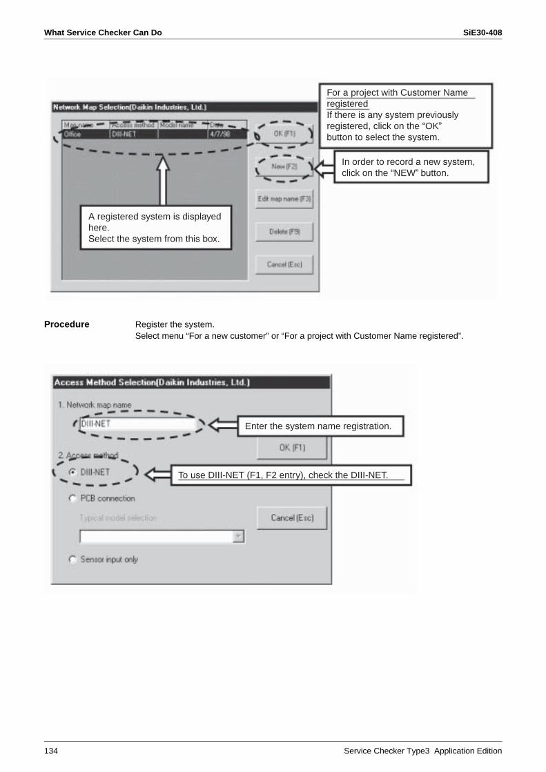
What Service Checker Can Do SiE30-408
134 Service Checker Type3 Application Edition
Procedure Register the system.Select menu “For a new customer” or “For a project with Customer Name registered”.
A registered system is displayed here.Select the system from this box.
For a project with Customer NameregisteredIf there is any system previouslyregistered, click on the “OK”button to select the system.
In order to record a new system,click on the “NEW” button.
Enter the system name registration.
To use DIII-NET (F1, F2 entry), check the DIII-NET.

SiE30-408 What Service Checker Can Do
Service Checker Type3 Application Edition 135
Procedure Select the method of registering and connecting systems.Enter the “System Name” and then select the “Connecting Method”.
For the connecting method, check either “DIII-NET” or “PCB connection”.
If you attempt to record data through the use of DIII-NET (F1, F2 connection), the warning above will appear on the window.In this case, clicking on the “Yes” will stop all systems connected to the DIII-NET for a period of several minutes, which has ever resulted in a claim regarding the server room of hospital.
If the Checker is connected to any other systems via Outdoor-Outdoor transmission besides the system of outdoor units connected, these other systems will go into “Restart standby (forced thermostat OFF)” mode.After the completion of “Restart standby” mode, the systems will be automatically reset, thus returning to operation prior to the standby.In the case of PCB connection, the systems will never go into “Restart standby” mode.
To use in PC board connectionCheck “PCB connection” and highlight anapplicable model in the list of Typical model selection.
Be sure to get permission from the customer and then click “Yes”.

What Service Checker Can Do SiE30-408
136 Service Checker Type3 Application Edition
Even tough all settings have been made and the window has been switched, if no data is read and the above error is displayed on the window, the following causes will be supposed.
• “F1 and F2” is not well connected, • PC board is not properly connected, or• The Checker is not power ON.
Therefore, check to be sure the above connections or else.
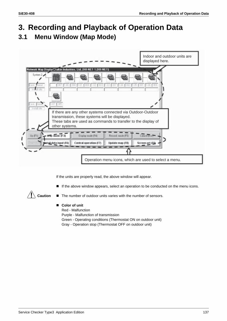
SiE30-408 Recording and Playback of Operation Data
Service Checker Type3 Application Edition 137
3. Recording and Playback of Operation Data3.1 Menu Window (Map Mode)
If the units are properly read, the above window will appear.
If the above window appears, select an operation to be conducted on the menu icons.
Caution The number of outdoor units varies with the number of sensors.
Color of unitRed - MalfunctionPurple - Malfunction of transmissionGreen - Operating conditions (Thermostat ON on outdoor unit)Gray - Operation stop (Thermostat OFF on outdoor unit)
Indoor and outdoor units aredisplayed here.
Operation menu icons, which are used to select a menu.
If there are any other systems connected via Outdoor-Outdoortransmission, these systems will be displayed.These tabs are used as commands to transfer to the display of other systems.

Recording and Playback of Operation Data SiE30-408
138 Service Checker Type3 Application Edition
Selecting recording mode (F5) will display the above window.
Click on the “Period. rcd. set” button and make setting of periodical recording.
Click on the “Period. rcd. set (F6)” button.
Keeping records Select recording mode (F5).
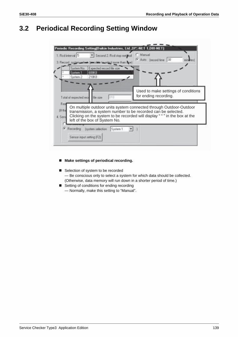
SiE30-408 Recording and Playback of Operation Data
Service Checker Type3 Application Edition 139
3.2 Periodical Recording Setting Window
Make settings of periodical recording.
Selection of system to be recorded — Be conscious only to select a system for which data should be collected. (Otherwise, data memory will run down in a shorter period of time.)Setting of conditions for ending recording— Normally, make this setting to “Manual”.
On multiple outdoor units system connected through Outdoor-Outdoortransmission, a system number to be recorded can be selected.Clicking on the system to be recorded will display “ x ” in the box at the left of the box of System No.
Used to make settings of conditionsfor ending recording.
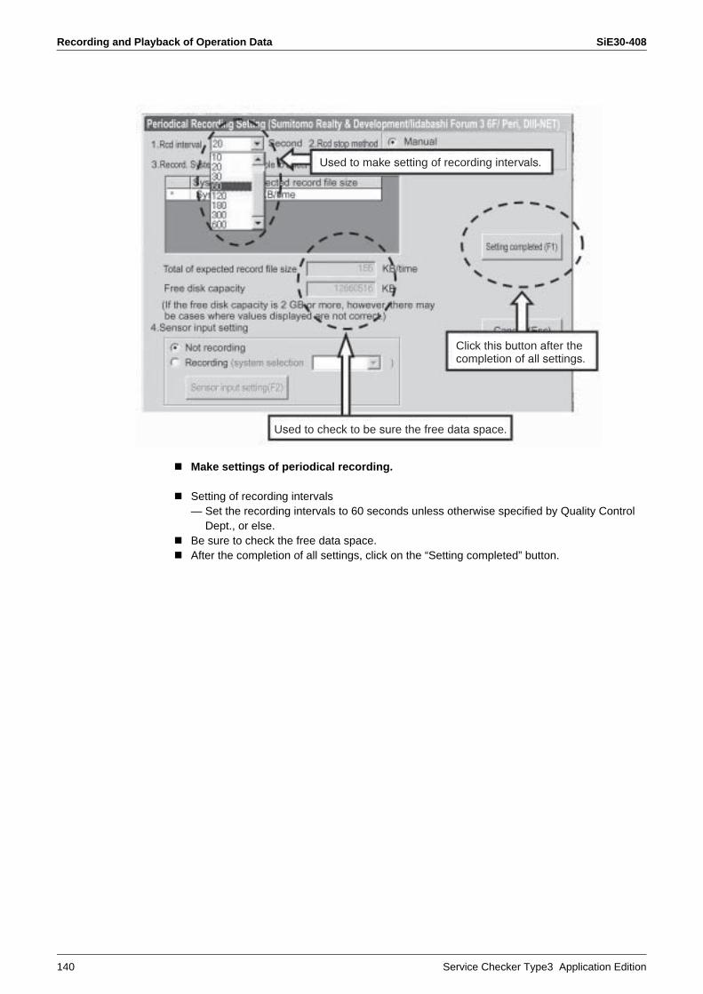
Recording and Playback of Operation Data SiE30-408
140 Service Checker Type3 Application Edition
Make settings of periodical recording.
Setting of recording intervals— Set the recording intervals to 60 seconds unless otherwise specified by Quality Control
Dept., or else.Be sure to check the free data space.After the completion of all settings, click on the “Setting completed” button.
Used to make setting of recording intervals.
Used to check to be sure the free data space.
Click this button after the completion of all settings.

SiE30-408 Recording and Playback of Operation Data
Service Checker Type3 Application Edition 141
Make settings of periodical recording.
Click on the “Period. rcd. Start” button.— Periodical recording starts —
Check whether or not the recording process is in progress.Check to be sure “In period. recording” is displayed.
To end recording
Click on the “Period. rcd. end” button.Terminate the Checker and then disconnect wirings.
Period. rcd. start button
Period. rcd. end button
Display of “In period. recording”
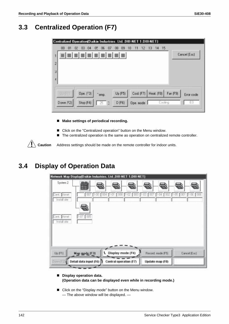
Recording and Playback of Operation Data SiE30-408
142 Service Checker Type3 Application Edition
3.3 Centralized Operation (F7)
Make settings of periodical recording.
Click on the "Centralized operation" button on the Menu window.The centralized operation is the same as operation on centralized remote controller.
Caution Address settings should be made on the remote controller for indoor units.
3.4 Display of Operation Data
Display operation data. (Operation data can be displayed even while in recording mode.)
Click on the “Display mode” button on the Menu window.— The above window will be displayed. —

SiE30-408 Recording and Playback of Operation Data
Service Checker Type3 Application Edition 143
Display of operation data (Operation data can be displayed even while in recording mode.)
Click on the “Detail data input” button on the Menu window.— The above window will be displayed. —Digital data will be displayed at the right on the window.Eight data (e.g. sensor or ON/OFF data) selected from the digital data will be displayed in analog form as shown in figure above.
• As to the operation data, the sampling timesvary with measuring items.
Example: One sampling in five minutes on themperature sensors.
• Furthermore, the sampling times differ between the Checker with DIII-NET and that in PC boardconnection.
• The number of data, which can be displayed on the window, also differs between the system with DIII-NET and that in PC board connection.
Display of digital data• Clicking on data item will display
the corresponding data in analogform in figure at the left on the window.
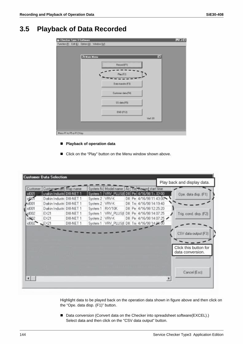
Recording and Playback of Operation Data SiE30-408
144 Service Checker Type3 Application Edition
3.5 Playback of Data Recorded
Playback of operation data
Click on the “Play” button on the Menu window shown above.
Highlight data to be played back on the operation data shown in figure above and then click on the “Ope. data disp. (F1)” button.
Data conversion (Convert data on the Checker into spreadsheet software(EXCEL).)Select data and then click on the "CSV data output" button.
Play back and display data.
Click this button for data conversion.
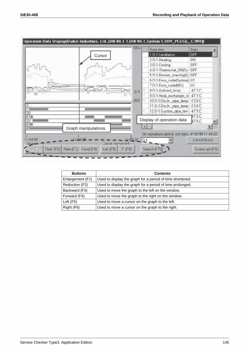
SiE30-408 Recording and Playback of Operation Data
Service Checker Type3 Application Edition 145
Cursor
Graph manipulations
Display of operation data
Buttons Contents
Enlargement (F1) Used to display the graph for a period of time shortened.
Reduction (F2) Used to display the graph for a period of time prolonged.
Backward (F3) Used to move the graph to the left on the window.
Forward (F4) Used to move the graph to the right on the window.
Left (F5) Used to move a cursor on the graph to the left.
Right (F6) Used to move a cursor on the graph to the right.
Collection and Playback of Data on Checker SiE30-408
146 Service Checker Type3 Application Edition
4. Collection and Playback of Data on Checker
Caution 1. Be sure to check the Nos. of system and indoor unit of the system, on which a malfunction occurs.• Example of checking method
If the centralized address is known — Carry out some operation (e.g. ON/OFF or set value changing) from the centralized remote controller and define the unit, which presents changes on the Checker.
If the centralized address is not known — Carry out operation from the remote controller for indoor unit and define the unit, which presents changes on the Checker.
2. In order to collect data using the DIII-NET, check with the customer that “Forced thermostat OFF” is surely activated once.• Provide the customer with an explanation that the system stops for a period of five minutes
at maximum and is automatically restart as soon as data is accepted.
3. Check to be sure the display time and settings on a personal computer.• Since time displayed on the Checker is corresponding to that displayed on the personal
computer, be sure to check and change the time.• If settings of screen saver and energy saving are made, there may be cases where the
personal computer freezes. Be sure to cancel the settings in advance.
4. Be sure to secure longitudinal data.• Be sure to check and take notes of on-site works and the times when malfunctions occur,
which will be needed to play back the data. Furthermore, it is advisable to check and take notes of any minimal works or changes.
5. Playback of data• Verify collected data by yourself once.
It is the best to diagnose the data on site where the data was collected, while referring to operation data and refrigerant circuit diagram. Furthermore, since it takes time to verify data at offices, be sure to request for the customer to allow the verification time with an explanation about the reason.The nearest way to enable data analysis by yourself is to have your own view on the collected data. If you always consult someone from the beginning, you will not develop the ability to analyze data.
For collection and playback of data on Checker
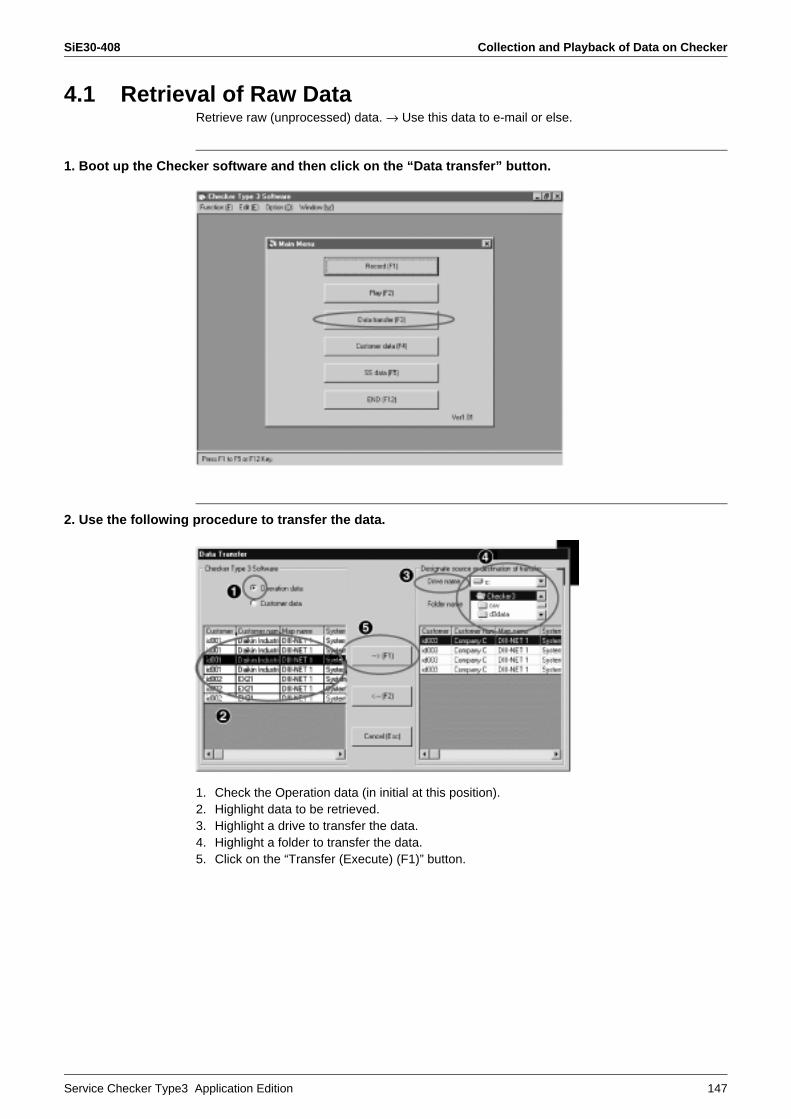
SiE30-408 Collection and Playback of Data on Checker
Service Checker Type3 Application Edition 147
4.1 Retrieval of Raw DataRetrieve raw (unprocessed) data. → Use this data to e-mail or else.
1. Boot up the Checker software and then click on the “Data transfer” button.
2. Use the following procedure to transfer the data.
1. Check the Operation data (in initial at this position).2. Highlight data to be retrieved.3. Highlight a drive to transfer the data.4. Highlight a folder to transfer the data.5. Click on the “Transfer (Execute) (F1)” button.
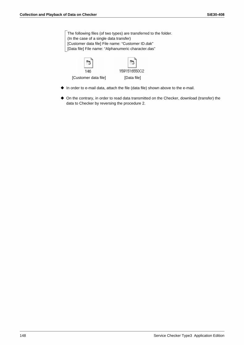
Collection and Playback of Data on Checker SiE30-408
148 Service Checker Type3 Application Edition
[Customer data file] [Data file]
In order to e-mail data, attach the file (data file) shown above to the e-mail.
On the contrary, in order to read data transmitted on the Checker, download (transfer) the data to Checker by reversing the procedure 2.
The following files (of two types) are transferred to the folder.(In the case of a single data transfer)[Customer data file] File name: “Customer ID.dak”[Data file] File name: “Alphanumeric character.das”
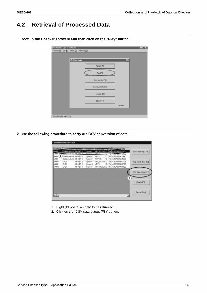
SiE30-408 Collection and Playback of Data on Checker
Service Checker Type3 Application Edition 149
4.2 Retrieval of Processed Data
1. Boot up the Checker software and then click on the "Play" button.
2. Use the following procedure to carry out CSV conversion of data.
1. Highlight operation data to be retrieved.2. Click on the “CSV data output (F3)” button.

Collection and Playback of Data on Checker SiE30-408
150 Service Checker Type3 Application Edition
3. Use the following procedure to save converted data.
1. Specify a place to save the data.2. Enter the data name.3. Click on the “Save” button.
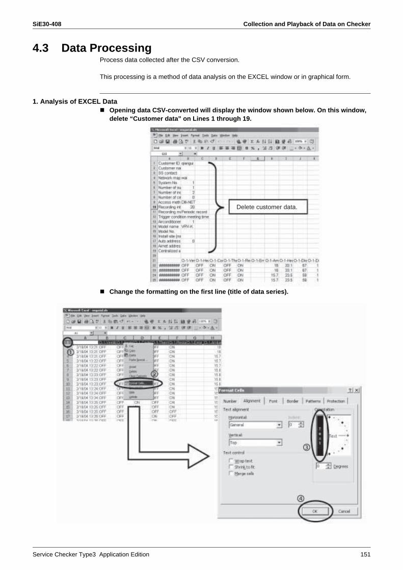
SiE30-408 Collection and Playback of Data on Checker
Service Checker Type3 Application Edition 151
4.3 Data ProcessingProcess data collected after the CSV conversion.
This processing is a method of data analysis on the EXCEL window or in graphical form.
1. Analysis of EXCEL DataOpening data CSV-converted will display the window shown below. On this window,delete “Customer data” on Lines 1 through 19.
Change the formatting on the first line (title of data series).
Delete customer data.
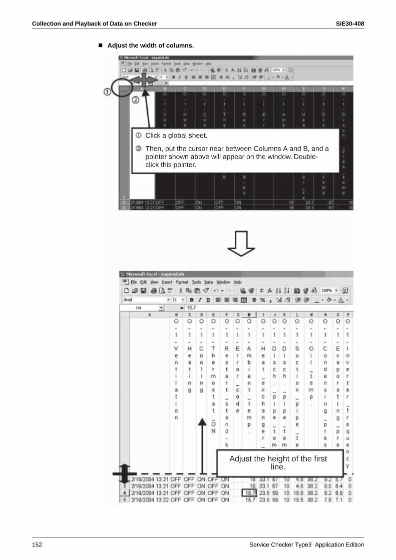
Collection and Playback of Data on Checker SiE30-408
152 Service Checker Type3 Application Edition
Adjust the width of columns.
Adjust the height of the firstline.
Click a global sheet.
Then, put the cursor near between Columns A and B, and apointer shown above will appear on the window. Double-click this pointer.
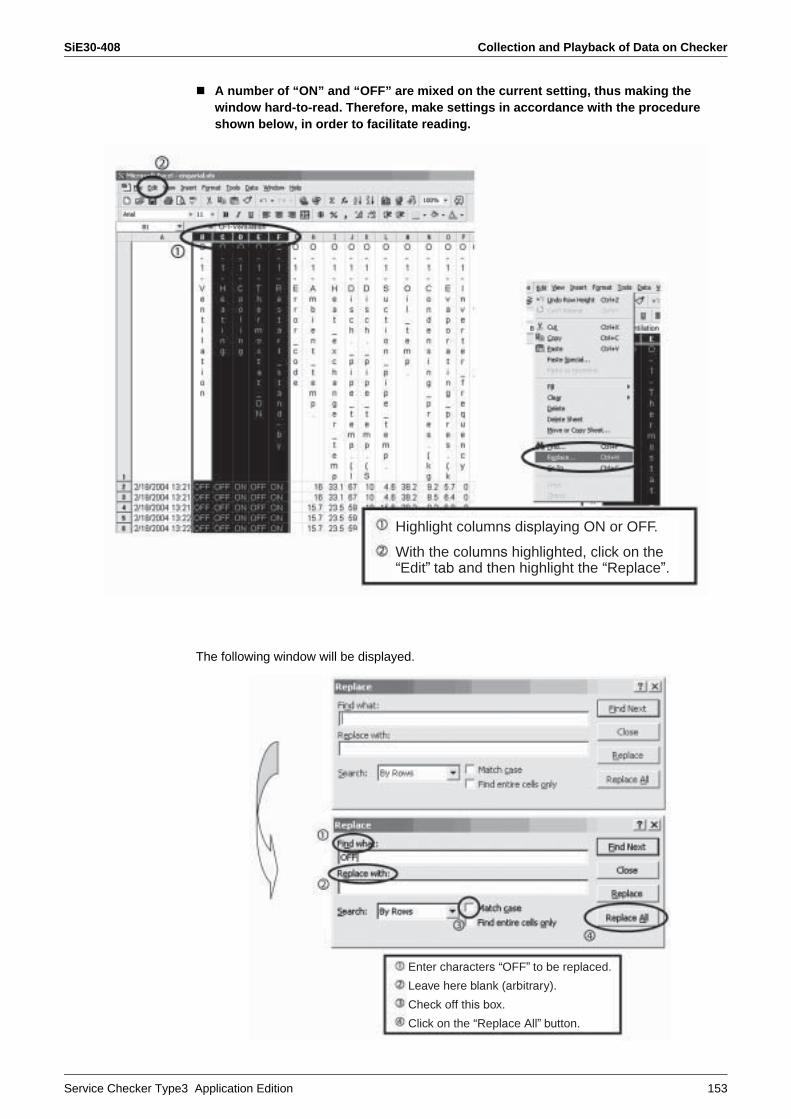
SiE30-408 Collection and Playback of Data on Checker
Service Checker Type3 Application Edition 153
A number of “ON” and “OFF” are mixed on the current setting, thus making the window hard-to-read. Therefore, make settings in accordance with the procedure shown below, in order to facilitate reading.
The following window will be displayed.
Highlight columns displaying ON or OFF.
With the columns highlighted, click on the “Edit” tab and then highlight the “Replace”.
Enter characters “OFF” to be replaced.
Leave here blank (arbitrary).
Check off this box.
Click on the “Replace All” button.
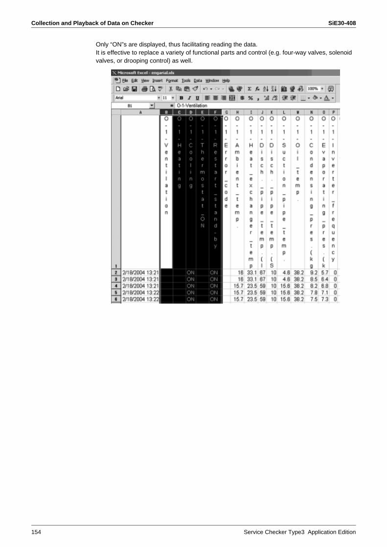
Collection and Playback of Data on Checker SiE30-408
154 Service Checker Type3 Application Edition
Only “ON”s are displayed, thus facilitating reading the data.It is effective to replace a variety of functional parts and control (e.g. four-way valves, solenoid valves, or drooping control) as well.
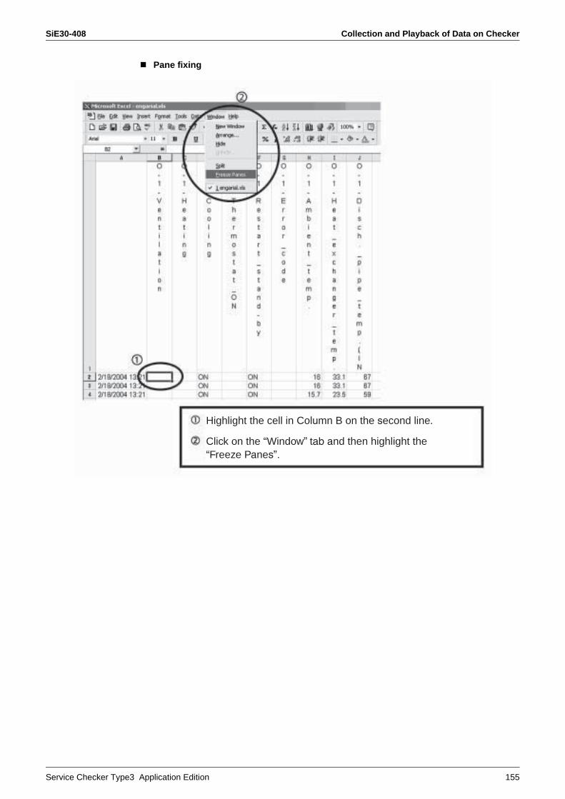
SiE30-408 Collection and Playback of Data on Checker
Service Checker Type3 Application Edition 155
Pane fixing
Highlight the cell in Column B on the second line.
Click on the “Window” tab and then highlight the “Freeze Panes”.

Collection and Playback of Data on Checker SiE30-408
156 Service Checker Type3 Application Edition
The title (on the first line) and time (in Column A) of data series is fixed, thus facilitating the Verification of data.
Range of fixed data
Scroll range
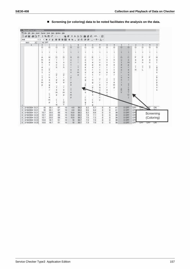
SiE30-408 Collection and Playback of Data on Checker
Service Checker Type3 Application Edition 157
Screening (or coloring) data to be noted facilitates the analysis on the data.
Screening(Coloring)
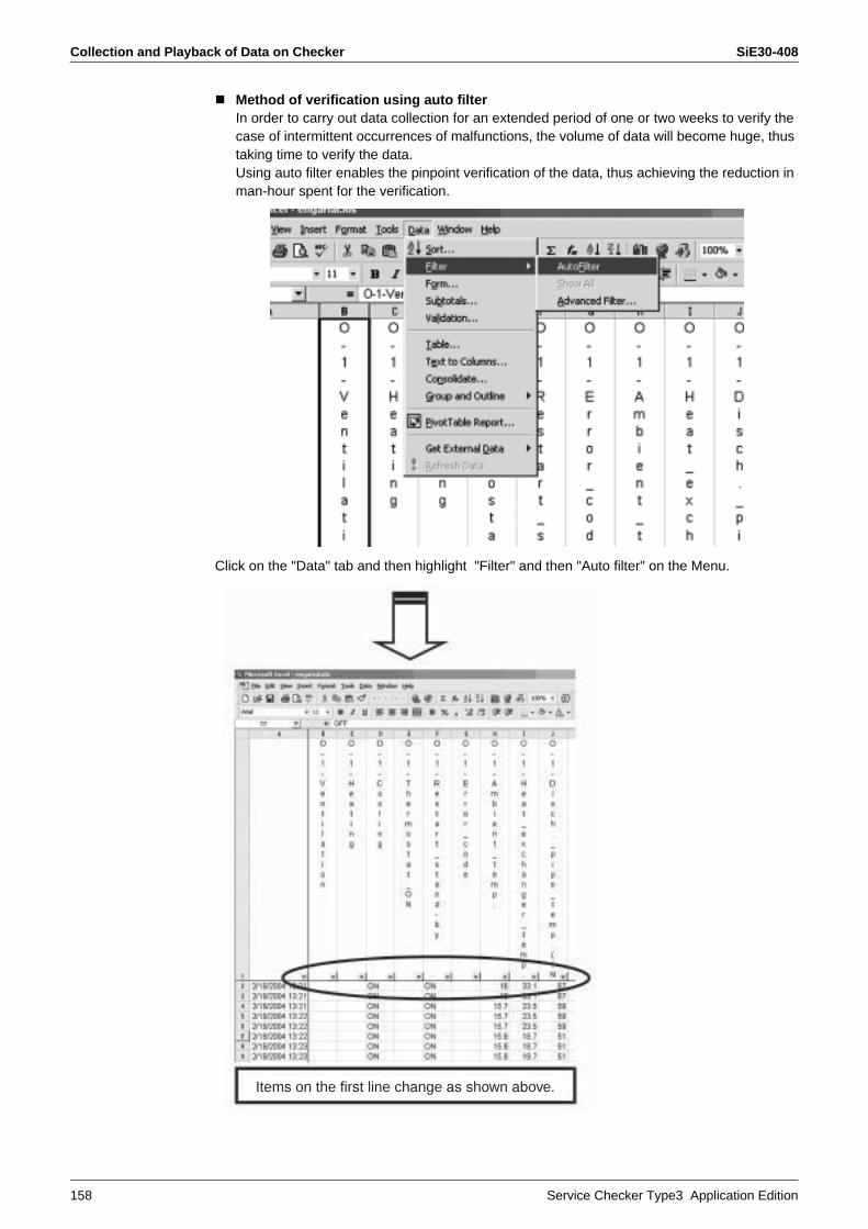
Collection and Playback of Data on Checker SiE30-408
158 Service Checker Type3 Application Edition
Method of verification using auto filterIn order to carry out data collection for an extended period of one or two weeks to verify the case of intermittent occurrences of malfunctions, the volume of data will become huge, thus taking time to verify the data.Using auto filter enables the pinpoint verification of the data, thus achieving the reduction in man-hour spent for the verification.
Click on the "Data" tab and then highlight "Filter" and then "Auto filter" on the Menu.
Items on the first line change as shown above.

SiE30-408 Collection and Playback of Data on Checker
Service Checker Type3 Application Edition 159
Pressing the button corresponding to items to be noted will list and display all elements contained in the column items.
Click “E0”.
Left figure lists the column items of “Error codes”. “E0” in the list shows that a malfunction has occurred.
øùùú
èééê
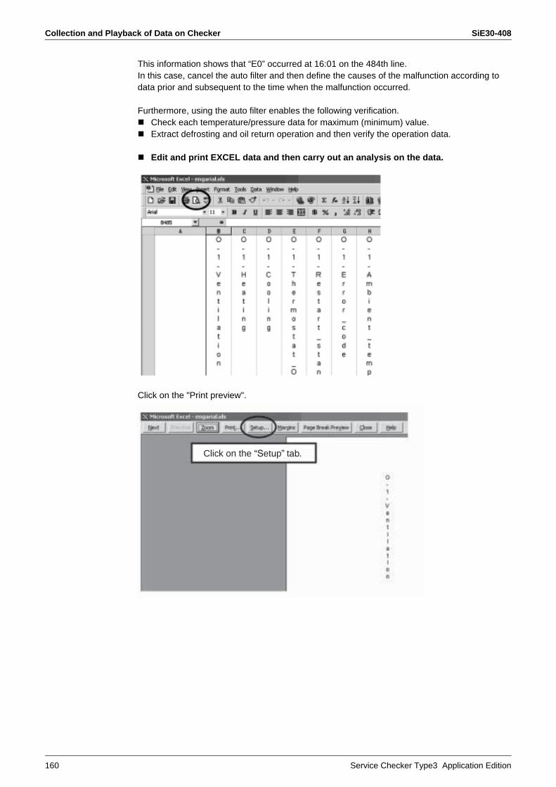
Collection and Playback of Data on Checker SiE30-408
160 Service Checker Type3 Application Edition
This information shows that “E0” occurred at 16:01 on the 484th line.In this case, cancel the auto filter and then define the causes of the malfunction according to data prior and subsequent to the time when the malfunction occurred.
Furthermore, using the auto filter enables the following verification.Check each temperature/pressure data for maximum (minimum) value.Extract defrosting and oil return operation and then verify the operation data.
Edit and print EXCEL data and then carry out an analysis on the data.
Click on the "Print preview".
Click on the “Setup” tab.
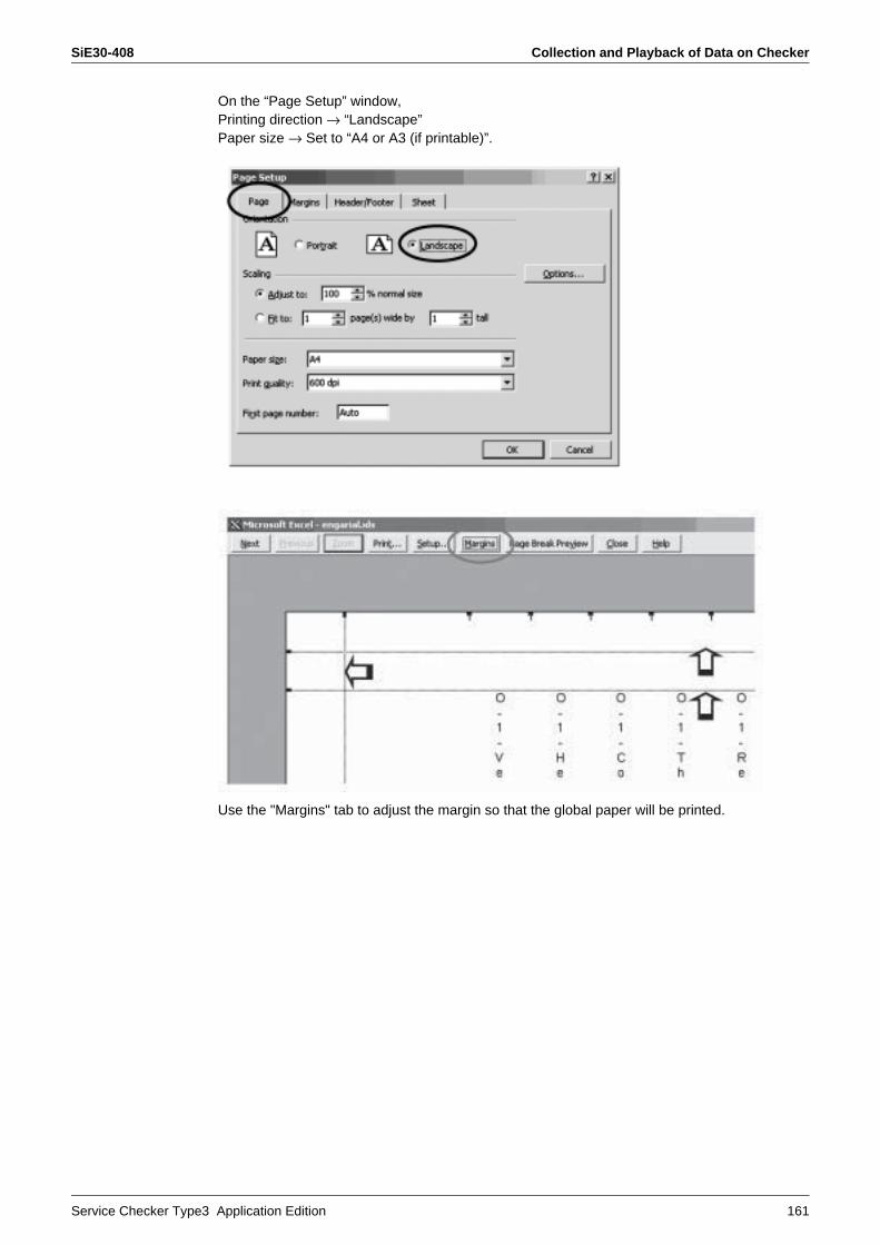
SiE30-408 Collection and Playback of Data on Checker
Service Checker Type3 Application Edition 161
On the “Page Setup” window,Printing direction → “Landscape”Paper size → Set to “A4 or A3 (if printable)”.
Use the "Margins" tab to adjust the margin so that the global paper will be printed.
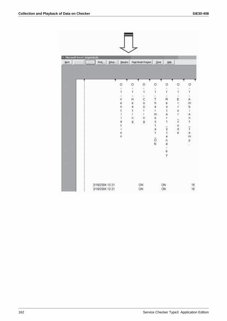
Collection and Playback of Data on Checker SiE30-408
162 Service Checker Type3 Application Edition

SiE30-408 Collection and Playback of Data on Checker
Service Checker Type3 Application Edition 163
Exit the “Print preview”, click on the "File" tab and then highlight the “Page Setup”.
On the “Sheet” menu within the “Page Setup” window, click on the “Print titles” and “Rows to repeat at top” and then click on any place on the first line.
→ “$1 : $1” will be entered.
Printing data according to the process above will print the first line at all times, thusfacilitating the analysis on the data.
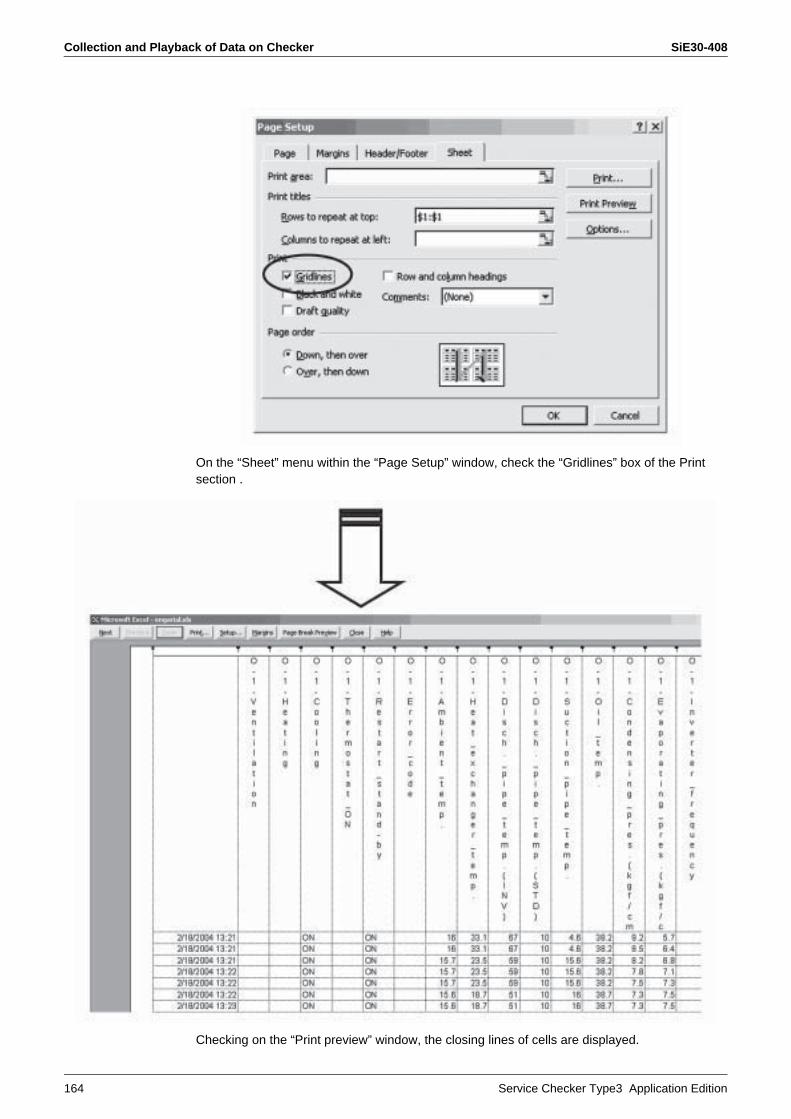
Collection and Playback of Data on Checker SiE30-408
164 Service Checker Type3 Application Edition
On the “Sheet” menu within the “Page Setup” window, check the “Gridlines” box of the Print section .
Checking on the “Print preview” window, the closing lines of cells are displayed.
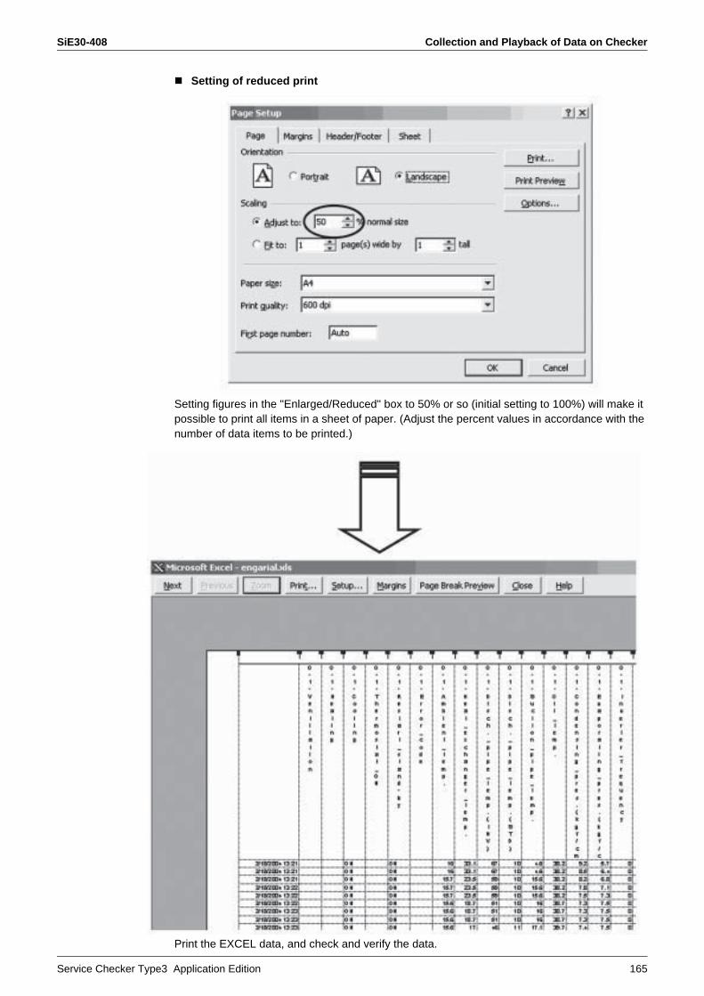
SiE30-408 Collection and Playback of Data on Checker
Service Checker Type3 Application Edition 165
Setting of reduced print
Setting figures in the "Enlarged/Reduced" box to 50% or so (initial setting to 100%) will make it possible to print all items in a sheet of paper. (Adjust the percent values in accordance with the number of data items to be printed.)
Print the EXCEL data, and check and verify the data.

Collection and Playback of Data on Checker SiE30-408
166 Service Checker Type3 Application Edition
2. Plotting in GraphThere are cases where it is hard to keep track of the overall variations of data on the CSV data.In this case, graphing the data will facilitate the verification of the data.(The following section shows an example of the graphing procedure.)
1. Method of graphing and organizing a global sheet.Run the graph wizard (graph insert).
Type of graph: “Line chart”
Form: “Shown in left figure”
Click on the “Next” button.
Graph wizard
Click on the “Next” button.
Graph insert

SiE30-408 Collection and Playback of Data on Checker
Service Checker Type3 Application Edition 167
Enter the title of graph andX- and Y-axis items.
Click on the “Legend” tab.
Click on the “Next” button.
Check the “Top”.
Click on the “Finish” button.
Check the “As new sheet”.
The
se it
ems
can
be e
nter
ed in
la
ter
stag
e.

Collection and Playback of Data on Checker SiE30-408
168 Service Checker Type3 Application Edition
4.4 Organizing Graph
All items contained in Checker data

SiE30-408 Collection and Playback of Data on Checker
Service Checker Type3 Application Edition 169
As shown in the window in previous page, all items contained in the Checker data are graphed. Therefore, for unnecessary items, click on the "Legend" (shown in window below) or item lines to delete them.
Items organized

Collection and Playback of Data on Checker SiE30-408
170 Service Checker Type3 Application Edition
4.5 Using Secondary Axis
If “Opening degree of electronic expansion valve” is selected from the data, due to large amplitude range of 0 to 2000 pulses, the temperature data will be gathered at the bottom of the graph, thus resulting in hard verification of data. Therefore, use the secondary axis to facilitate the reading of the data.
Temperature data
Opening degree of electronic expansion valve
Secondary axis
On the “Format Data Series”, click on the
“Axis” and then check the “Secondary axis”
in the item of “plot series on”, and the graph
of electronic expansion valve will be plotted
on the secondary axis like the sample graph,
thus facilitating the reading of temparature
data. (If two or more EVs are mounted,
repeat the same procedure.)
Clicking on the graph line of the electronic expansion
valve will display a pointer on the line as shown and
marked with “O” in the left figure.
In this state, by right-clicking on the pointer, the
Window shown on the left will appear. Then, click on
“Format Data Series”.

SiE30-408 Collection and Playback of Data on Checker
Service Checker Type3 Application Edition 171
[Reference 1]
[Reference 2]
“Patterns” menu on the “Format DataSeries” enables changes of the “Color/Weight” and others of the graphLines.
Before the startup of graph wizard, narrow data
down to some extent and highlight “Hide”.
Doing so will require no execution of Section 1-2.
Highlight columns not to be displayed Right-click
Highlight “Hide”.

Collection and Playback of Data on Checker SiE30-408
172 Service Checker Type3 Application Edition
4.6 Traverse of X AxisSince the intersection of X and Y axes is “0” on the current graph , change this intersection to facilitate the reading of the graph.
Click on the graduation line of the numerical value axis.(A pointer will appear on the numerical value axis.)Right-clicking on the pointer will display the “Format Gridlines”window.
Set the intersection with X axisto the minimum value of Y axis.
The item of X axis traverses to the minimum value of Y axis,thus facilitating the reading of the graph.
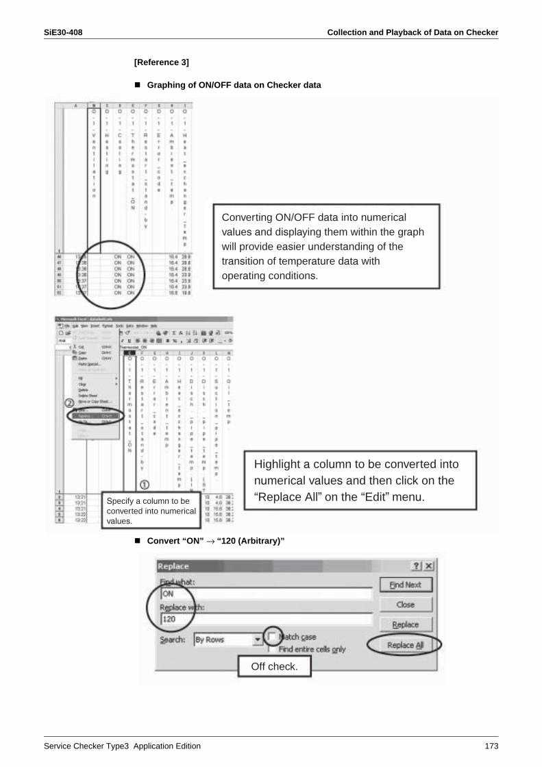
SiE30-408 Collection and Playback of Data on Checker
Service Checker Type3 Application Edition 173
[Reference 3]
Graphing of ON/OFF data on Checker data
Convert “ON” → “120 (Arbitrary)”
Converting ON/OFF data into numericalvalues and displaying them within the graphwill provide easier understanding of the transition of temperature data with operating conditions.
Specify a column to beconverted into numericalvalues.
Highlight a column to be converted into numerical values and then click on the “Replace All” on the “Edit” menu.
Off check.

Collection and Playback of Data on Checker SiE30-408
174 Service Checker Type3 Application Edition
[Reference 4]
Adding data after the graph is plotted.
Since “ON” data is converted into a numericalvalue (120), use the graphing procedure to retrieve the data in the graph.
Right-click on the graph plotted andthen click on the “Source Data”.
Clicking on the “Add” button will add new series (e.g. Series 52 in figure on the left).
Then, enter an item name to beadded.
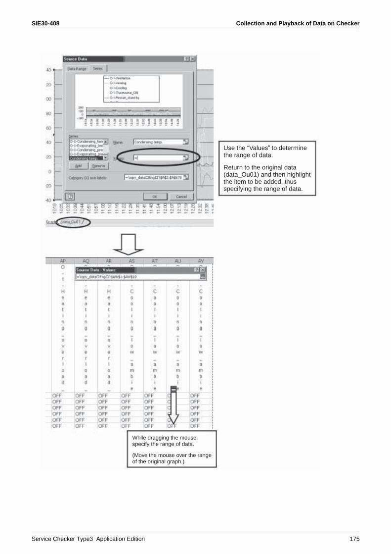
SiE30-408 Collection and Playback of Data on Checker
Service Checker Type3 Application Edition 175
Use the “Values” to determine the range of data.
Return to the original data(data_Ou01) and then highlight the item to be added, thusspecifying the range of data.
While dragging the mouse, specify the range of data.
(Move the mouse over the rangeof the original graph.)

Collection and Playback of Data on Checker SiE30-408
176 Service Checker Type3 Application Edition
When the range of data to beadded is written, click “OK”.
The data series (condensing temperature) is additionally displayed within the graph.

SiE30-408 Collection and Playback of Data on Checker
Service Checker Type3 Application Edition 177
[Reference 5]
Plotting of data on indoor and outdoor units in one and same graph
Caution The data on indoor units are sampled at 5-minute intervals and, therefore, do not follow the data on outdoor units on an anytime basis.
Select data to be plotted in one and same graphfrom data on indoor units and copy the data bycolumn.
Boot data on outdoor units and click on aplace to insert data on indoor units, andthen paste the data to this place.
Data on indoor and outdoor units aredisplayed on one and same sheet, thusmaking it possible to plot the data in agraph.

Points of Analysis SiE30-408
178 Service Checker Type3 Application Edition
5. Points of Analysis5.1 Method of Use by Symptom
In the Case of Faulty Compressor1. While the compressor is running:
Compressor oil temp. > Evaporating temp. (Low pressure saturation temp.) + 10°CDischarge superheated degree (Discharge pipe temp. − Condensing temp. (High pressure saturation temp. ) > 10°C(however, 5°C within 12 minutes after startup.)Compressor oil temp. < 80°C (If this oil temp. reaches 80°C or more, the oil viscosity will be degraded.)Check whether or not suction superheated degree is on a wet trend.(Check to be sure the control of outdoor unit EVs while in heating or that of indoor unit EVs while in cooling.) ← (Check whether or not the EVs are throttled.)
2. While the compressor stops running:Ambient temp. + 15°C < Oil temp. < 80°C (Pass/Fail judgment of crankcase heater)
In the Case of Malfunction of CoolingCheck to be sure the temperature detected by pressure sensor has reached and kept constant at target pressure (evaporating temperature).Check to be sure the temperature detected by the liquid pipe thermistor of indoor unit reaches about 5 to 7°C, and furthermore the temperature detected by the gas pipe thermistor is about 10°C.In addition, check to be sure the opening degrees of indoor unit EVs are about 500 to 1000 pulses, except while in capacity control mode. (While in capacity control mode, the EV opening degrees are controlled toward closing side. Thus, the superheated degree will have an increasing tendency.)If the indoor unit EVs have uniform and same opening degrees, outdoor units have output control instructions. In this case, check to be sure the data on outdoor units.
In the Case of Malfunction of Heating Check to be sure the temperature detected by high pressure sensor has reached and kept constant at target temperature (condensing temperature).Check to be sure the temperature detected by the liquid pipe thermistor of indoor units reaches about 38°C.Check to be sure the opening degrees of indoor unit EVs are about 500 to 1000 pulses.(If the EVs fully open (i.e., the opening degree is 2000 pulses (or approx. 1400 pulses for R410A), refrigerant may be charged excessively or heating load may reach a high level.)High pressure − Liquid pressure > 2 kg/cm2 at service ports on stop valve on the outdoor unit side, which cannot be checked on the Checker.(Due to the flow characteristics of EVs, unless the differential pressure between the front and rear of the valve is 2 kg/cm2, the liquid is hard to flow.)
5.2 To Conduct AnalysisIn order to collect or analyze the Checker data,
First of all, make Pass/Fail judgment on functional partsFor accurate data collection, be sure to check functional parts for any problem.Example: Even though the thermistor showed a normal value at an ambient temperature, the detection data got out of order with increasing temperature.(Particularly, to collect data on products manufactured in many years ago, give consideration to the example mentioned above.)
SiE30-408 Points of Analysis
Service Checker Type3 Application Edition 179
Pay attention to “Condensing temp./Evaporating temp.” rather than to “High pressure/Low pressure”.High and low pressures detected by each pressure sensor are displayed in values, converted into pressure equivalent saturation temperatures, and used as target values for the capacity control. Therefore, it is immediately obvious whether or not the target temperatures are achieved.
Check each drooping/protection control for operating conditions and think about why this control is performed.
Each stepping down/protection control is used to ensure reliability, not to protect malfunctions.For example, do not consider that “The unit does not cool (or heat) due to control activated”. Verify why the control is activated, in accordance with other data.
Are “discharge superheated degree and suction superheated degree” kept at proper levels, respectively?Most of malfunctions on compressors result from “wet operation”. Referring to the diagnosis procedure on the preceding page, check to be sure the discharge and suction superheated degrees are kept at proper levels.
Use data on indoor units as reference values.Data on temperatures and Evs' opening degrees of indoor units are updated every five minutes. By contrast, data on outdoor units are updated earlier than that. As a result, even though data on outdoor units can be collected, the data is not synchronized with that while in malfunction in most cases. Give consideration to this point in order to verify the data on indoor units.
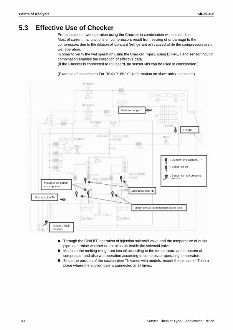
Points of Analysis SiE30-408
180 Service Checker Type3 Application Edition
5.3 Effective Use of CheckerProbe causes of wet operation using the Checker in combination with sensor kits.Most of current malfunctions on compressors result from seizing of or damage to the compressors due to the dilution of lubricant (refrigerant oil) caused while the compressors are in wet operation.In order to verify the wet operation using the Checker Type3, using DIII-NET and sensor input in combination enables the collection of effective data.(If the Checker is connected to PC board, no sensor kits can be used in combination.)
(Example of connection) For RSXYP16KJY1 (Information on slave units is omitted.)
Through the ON/OFF operation of Injection solenoid valve and the temperature of outlet pipe, determine whether or not oil leaks inside the solenoid valve.Measure the melting refrigerant into oil according to the temperature at the bottom of compressor and also wet operation according to compressor operating temperature.Since the position of the suction pipe Th varies with models, mount the sensor kit Th in a place where the suction pipe is connected at all times.
Mount to the bottomof compressor
Suction pipe Th
Measure liquidpressure.
Mount sensor kit to injection outlet pipe.
Discharge pipe Th
: Outdoor unit standard Th
: Sensor kit Th
: Sensor kit high pressuresensor
Heat exchange Th
Header Th

SiE30-408 Points of Analysis
Service Checker Type3 Application Edition 181
5.4 Example of Checker Connection
Equipment subject to check
Main unit of TYPE3
Sensor inputsection
Pressuresection
Thermistor
F1, F2 terminals
Personal Computer
Mount to pointssubject to checks.
Sensor kit
F1, F2 terminals(Whichever IN-OUT or
OUT-OUT is applicable.)

Points of Analysis SiE30-408
182 Service Checker Type3 Application Edition
5.5 Method of Mounting Sensor Kit1. Determine the position to mount thermistor.2. Clean the pipe. (Wipe condensate or dirt off the pipe, if any.)
Caution Be sure to stop equipment before mounting the thermistor to a low temperature pipe.(If the pipe is condensed or frozen, no accurate measurements are enabled.)
3. Bring the thermistor into close contact with the pipe in parallel and tightly wind aluminum tape around them.
4. Wrap anti-sweat insulation tube or the like around pipe and thermistor (in order to make them insensitive to ambient temperature.
5. Tie both ends of the anti-sweat vessel.
Sensor kit thermistor
Secure with aluminum tape.
Bind here.
Bind here.
Wrap anti-sweat insulation tube or the like andthen tie both ends of the tube with tie-wrap.
Pipe

SiE30-408 Points of Analysis
Service Checker Type3 Application Edition 183
5.6 Place to Save Data
The DIII data is used to save transmission data on air conditioners.However, this data cannot be analyzed with the Service Checker.(If Quality Control Department from factory gives an instruction, collect and transmit the data.)
Be noted that the local disk varies with PC to be used.
Data is saved in this folder.
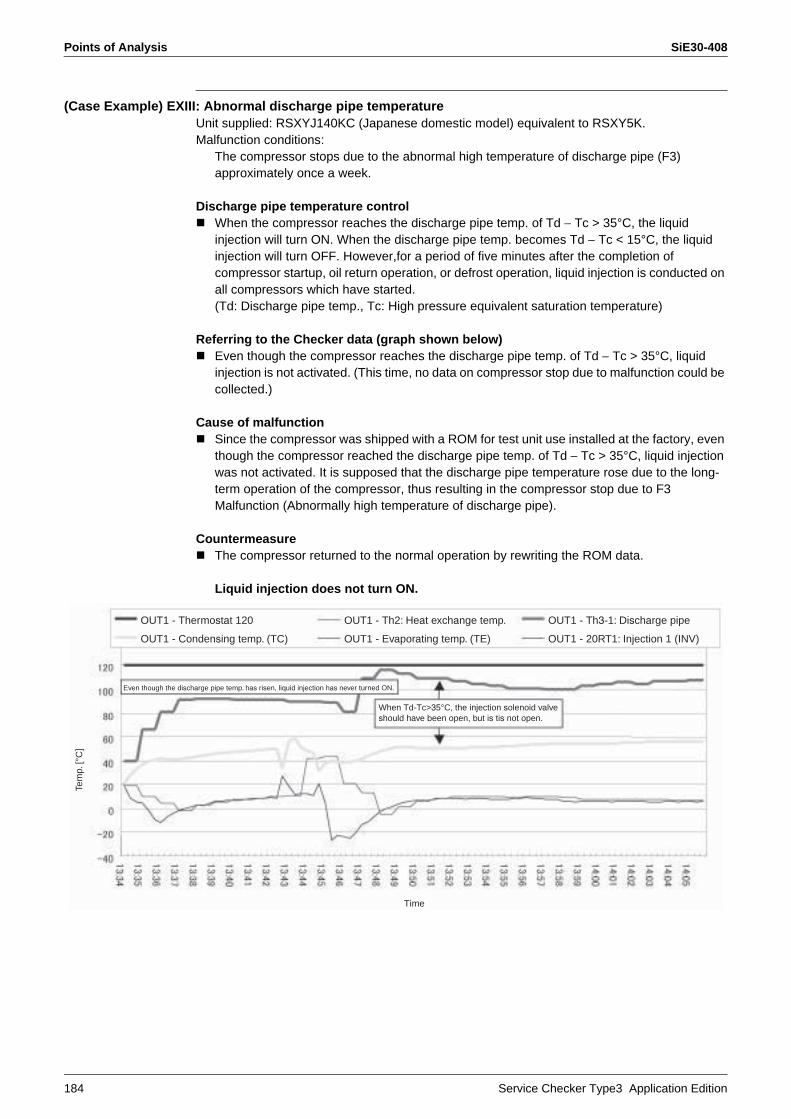
Points of Analysis SiE30-408
184 Service Checker Type3 Application Edition
(Case Example) EXIII: Abnormal discharge pipe temperatureUnit supplied: RSXYJ140KC (Japanese domestic model) equivalent to RSXY5K.Malfunction conditions:
The compressor stops due to the abnormal high temperature of discharge pipe (F3) approximately once a week.
Discharge pipe temperature controlWhen the compressor reaches the discharge pipe temp. of Td − Tc > 35°C, the liquid injection will turn ON. When the discharge pipe temp. becomes Td − Tc < 15°C, the liquid injection will turn OFF. However,for a period of five minutes after the completion of compressor startup, oil return operation, or defrost operation, liquid injection is conducted on all compressors which have started. (Td: Discharge pipe temp., Tc: High pressure equivalent saturation temperature)
Referring to the Checker data (graph shown below)Even though the compressor reaches the discharge pipe temp. of Td − Tc > 35°C, liquid injection is not activated. (This time, no data on compressor stop due to malfunction could be collected.)
Cause of malfunctionSince the compressor was shipped with a ROM for test unit use installed at the factory, even though the compressor reached the discharge pipe temp. of Td − Tc > 35°C, liquid injection was not activated. It is supposed that the discharge pipe temperature rose due to the long-term operation of the compressor, thus resulting in the compressor stop due to F3 Malfunction (Abnormally high temperature of discharge pipe).
CountermeasureThe compressor returned to the normal operation by rewriting the ROM data.
Liquid injection does not turn ON.
OUT1 - Thermostat 120
Even though the discharge pipe temp. has risen, liquid injection has never turned ON.
OUT1 - Condensing temp. (TC)
OUT1 - Th2: Heat exchange temp.
OUT1 - Evaporating temp. (TE)
When Td-Tc>35°C, the injection solenoid valve should have been open, but is tis not open.
OUT1 - Th3-1: Discharge pipe
OUT1 - 20RT1: Injection 1 (INV)
Tem
p. [°
C]
Time

SiE30-408 Points of Analysis
Service Checker Type3 Application Edition 185
(Case Example) VRV II Heat recovery type: Malfunction of heatingUnit supplied: REYQ16M (Heat recovery type)Malfunction conditions:
Indoor units produce abnormal sounds sometimes and do not heat up.
Referring to Checker data on occurrence of malfunction while in all-unit heating operation (graph shown on the following page)
The suction pipe temperature has risen up to approximately 70°C.Low pressure has reached approximately 1.5 MPa.Discharge pipe stepping down control has been activated.High pressure has not been stabilized.
* According to the data above, it can be judged that high pressure gas may be bypassed to low pressure side somewhere. Furthermore, since a temperature at the stop valve area of suction gas pipe provided on site was measured and found to be approximately 50°C, it can be judged that the gas is bypassed on the indoor unit side.(The suction gas pipe is only used in cooling operation. Furthermore, this pipe is directly connected to the compressor, thus causing no flow of high pressure gas.)
Referring to verification data on indoor units
Procedure for indoor unit operationAmong five indoor units connected, stop four indoor units in cooling mode (in order to set the opening degree of the indoor unit expansion valve to 0 pls).Operate the remaining one indoor unit in heating test operation mode. (The reason is that if there is no indoor unit with thermostat ON while in heating mode, no high pressure gas will flow in the discharge gas pipe.)Making measurement of indoor unit operation data according to the aforementioned procedure will have an indoor unit which has an increased gas pipe temperature even though no refrigerant flow at 0-pls opening degree of the electronic expansion valve and the liquid and suction pipes are only connected. As a result, it can be judged that the indoor unit with the increased gas pipe temperature has discharge and suction pipes connected other way round.
Cause of malfunctionOn the outdoor unit side, discharge gas was bypassed to the suction pipe. As a result, the suction pipe temperature rose following with a rise of discharge pipe temperature and the activation of discharge pipe temperature control, which disabled the continuous operation of the compressor leading to the unstable state of high pressure. Furthermore, on the indoor unit side, due to no discharge gas flow, no indoor units heated up and back pressure was applied to the check valve, thus resulting in the occurrence of abnormal sounds.
CountermeasurePipes of indoor units (1), (3), and (4) provided on site were rectified.
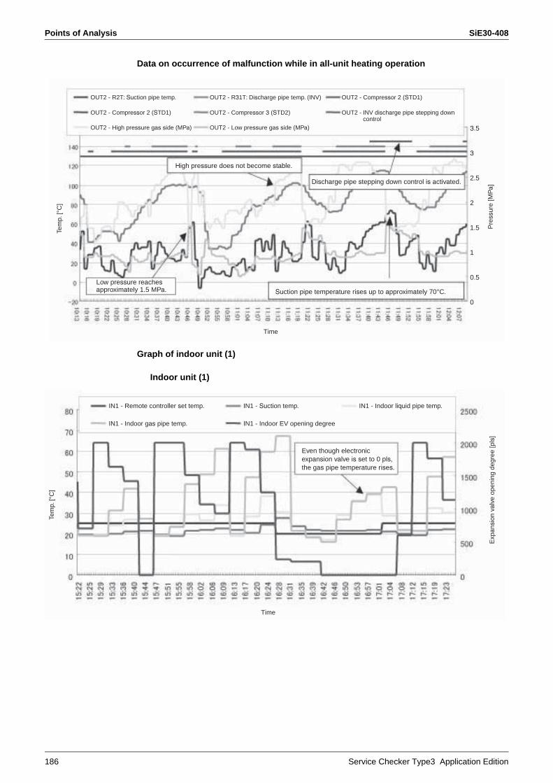
Points of Analysis SiE30-408
186 Service Checker Type3 Application Edition
Data on occurrence of malfunction while in all-unit heating operation
Graph of indoor unit (1)
Indoor unit (1)
OUT2 - R2T: Suction pipe temp.
OUT2 - Compressor 2 (STD1)
OUT2 - High pressure gas side (MPa)
OUT2 - R31T: Discharge pipe temp. (INV)
OUT2 - Compressor 3 (STD2)
OUT2 - Low pressure gas side (MPa)
OUT2 - Compressor 2 (STD1)
OUT2 - INV discharge pipe stepping down control
Suction pipe temperature rises up to approximately 70°C.
Tem
p. [°
C]
Time
Pre
ssur
e [M
Pa]
Low pressure reachesapproximately 1.5 MPa.
High pressure does not become stable.
Discharge pipe stepping down control is activated.
3.5
3
2.5
2
1.5
1
0.5
0
IN1 - Remote controller set temp.
IN1 - Indoor gas pipe temp.
IN1 - Suction temp. IN1 - Indoor liquid pipe temp.
IN1 - Indoor EV opening degree
Even though electronic expansion valve is set to 0 pls,the gas pipe temperature rises.
Tem
p. [°
C]
Time
Exp
ansi
on v
alve
ope
ning
deg
ree
[pls
]
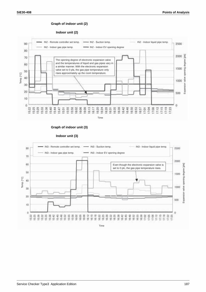
SiE30-408 Points of Analysis
Service Checker Type3 Application Edition 187
Graph of indoor unit (2)
Indoor unit (2)
Graph of indoor unit (3)
Indoor unit (3)
IN2 - Remote controller set temp.
IN2 - Indoor gas pipe temp.
IN2 - Suction temp. IN2 - Indoor liquid pipe temp.
IN2 - Indoor EV opening degree
Tem
p. [°
C]
Time
Exp
ansi
on v
alve
ope
ning
deg
ree
[pls
]
The opening degree of electronic expansion valve and the temperatures of liquid and gas pipes vary in a similar manner. With the electronic expansionvalve set to 0 pls, the gas pipe temperature only rises approximately up the room temperature.
IN3 - Remote controller set temp.
IN3 - Indoor gas pipe temp.
IN3 - Suction temp. IN3 - Indoor liquid pipe temp.
IN3 - Indoor EV opening degree
Tem
p. [°
C]
Time
Exp
ansi
on v
alve
ope
ning
deg
ree
[pls
]
Even though the electronic expansion valve isset to 0 plc, the gas pipe temperature rises.
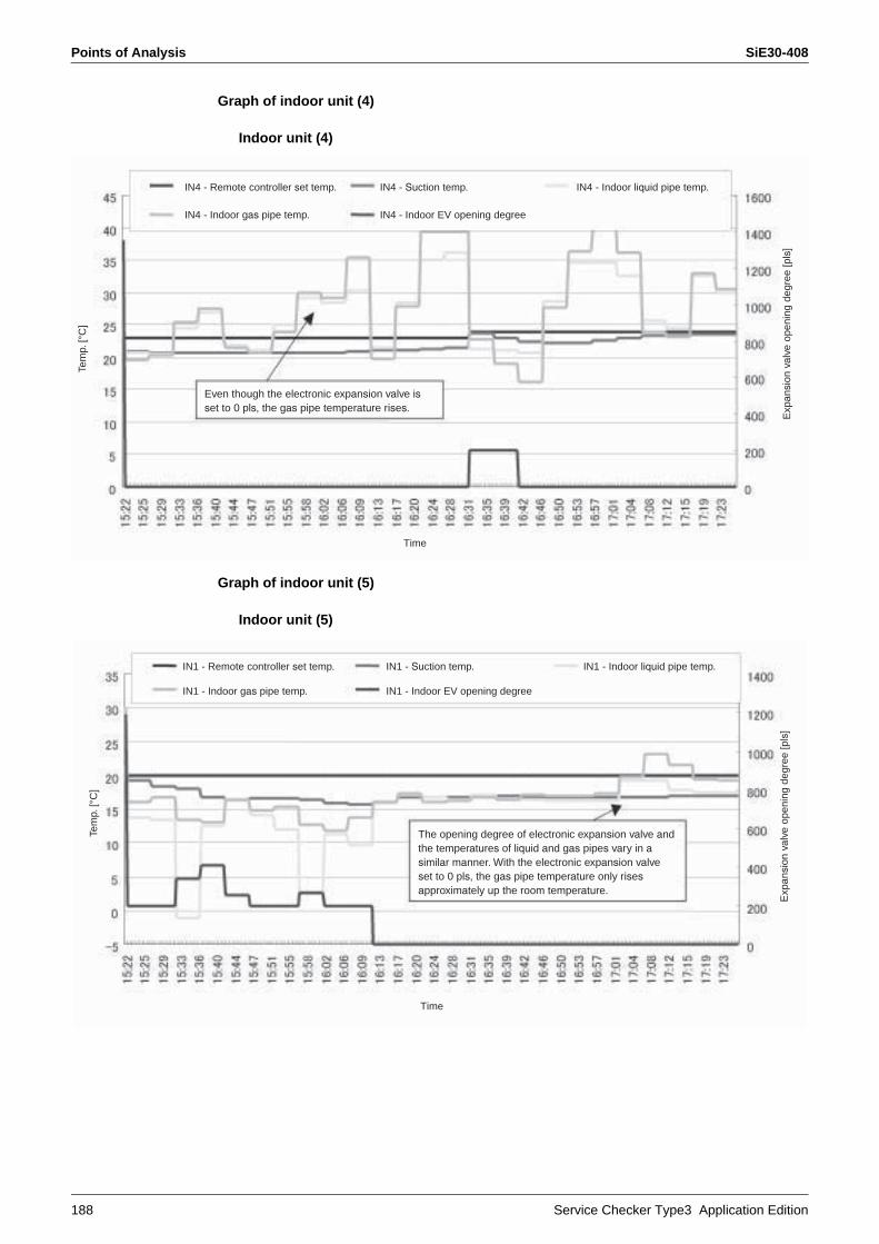
Points of Analysis SiE30-408
188 Service Checker Type3 Application Edition
Graph of indoor unit (4)
Indoor unit (4)
Graph of indoor unit (5)
Indoor unit (5)
IN4 - Remote controller set temp.
IN4 - Indoor gas pipe temp.
IN4 - Suction temp. IN4 - Indoor liquid pipe temp.
IN4 - Indoor EV opening degree
Tem
p. [°
C]
Time
Exp
ansi
on v
alve
ope
ning
deg
ree
[pls
]
Even though the electronic expansion valve isset to 0 pls, the gas pipe temperature rises.
IN1 - Remote controller set temp.
IN1 - Indoor gas pipe temp.
IN1 - Suction temp. IN1 - Indoor liquid pipe temp.
IN1 - Indoor EV opening degree
Tem
p. [°
C]
Time
Exp
ansi
on v
alve
ope
ning
deg
ree
[pls
]
The opening degree of electronic expansion valve andthe temperatures of liquid and gas pipes vary in asimilar manner. With the electronic expansion valve set to 0 pls, the gas pipe temperature only risesapproximately up the room temperature.

SiE30-408 Points of Analysis
Service Checker Type3 Application Edition 189
(Case Example) Ve-up STD RSXYP 5-10L:Malfunction of heating (Indoor units are all in fan operation mode.)
Features of dataThe system is under heating overload (high pressure stepping down) control.The condensing temperature (high pressure) has reached the target value.The operating frequency of INV compressor does not increase.(STD compressor stops running.)The opening degree of outdoor unit EV is small.
DiagnosisThe compressor is low in capacity but reaches the target value of Tc and also under heating overload control. Consequently, the compressor load does not increase even if an increase of the capacity is demanded by the indoor unit.
CauseNon-condensable gas may have mixed in the refrigerant system.
CountermeasureThe system returned to good running conditions by the replacement of refrigerant.(Abnormal rise in high pressure occurred on the recovery unit while in refrigerant recovery operation. ←Non-condensable gas)
OUT1 - R2-11T: Heat exchange temp 1.
OUT1 - Evaporating temp. (Te)
OUT1 - Outdoor unit EV opening degree 1
OUT1 - R3-11T: Discharge temp. (INV)
OUT1 - INV frequency
OUT1 - R6-1T: Suction temp.
OUT1 - Heating overload 2
OUT1 - Condensation temp. (Tc)
OUT1 - Heating overload 3
OUT1 - Outdoor unit EV opening degree 2
Tem
p. [°
C]
Time
Exp
ansi
on v
alve
ope
ning
deg
ree
[pls
]
Tc has reached the target value for heating operation. Indoor unit is in forced operation.
Heating overload 2 (High pressure stepping down)
Heating overload 3 (High pressure drooping)
INV compressor is in operationat a minimum frequency.
Opening degree of outdoor unit EV is small (Circulating refrigerant quantity is low.)
Points of Analysis SiE30-408
190 Service Checker Type3 Application Edition
SiE30-408
Appendix 191
1. Characteristics of Refrigerant..............................................................1921.1 R22.......................................................................................................1921.2 R407C ..................................................................................................1931.3 R410A ..................................................................................................195
2. Psychrometric Chart............................................................................1973. How to Calculate Cooling / Heating Capacity .....................................1984. Field Settings for the Replacement of the Spare Control PC Board ...1995. Adaptors for Connection of Air Conditioners.......................................201
5.1 Wiring Adaptor for Electrical Appendices (2) <KRP4A51, 52, 53, 54> .......................................................................201
5.2 Wiring Adaptor for Electrical Appendices (1) (KRP2A61, 62) .....................................................................................209
5.3 External Control Adaptor of Outdoor Unit <DTA104A53, 61, 62>..........................................................................216
5.4 DIII-NET Expander Adaptor <DTA109A51>.........................................2215.5 Versatile Usage ....................................................................................225
6. How to replace the Compressor..........................................................2287. HRV-Related .......................................................................................229
7.1 Group Interlock Control ........................................................................2297.2 Centralized Control System..................................................................2347.3 Examples of Mistakes in Wiring and System Designing ......................2367.4 Additional Functions .............................................................................2377.5 Central Control System (DCS302B61).................................................242

Characteristics of Refrigerant SiE30-408
192 Appendix
1. Characteristics of Refrigerant1.1 R22
* The pressure values in the diagram show absolute pressure.Deduct 0.1MPa to obtain gauge pressure.
P (MPa)
s (k
J/(k
g · K
))t
(°C
)v
(m³/
kg)
x (-
)
h(kj
/kg)
6.0
5.0
4.0
3.0
2.0
1.0
0.6
0.5
0.4
0.3
0.2
0.1
0.06
0.05
0.04
0.03
0.02
0.01
0.00
6
6.0
5.0
4.0
3.0
2.0
1.0
0.6
0.5
0.4
0.3
0.2
0.1
0.06
0.05
0.04
0.03
0.02
0.01
0.00
6
0.00
20.
003
0.00
40.
006 0.
008 0.
015
0.02
5
0.01
0.02 0.
03 0.04 0.06
0.08 0.15
0.25
0.1
0.2
2.22.1
2.02.3
2.4
0.3
0.4
0.6
0.8
1.0
1.5
v=
2.0
t = 200
s = 2.5
s = 1.5
v =
0.00
15
t = 30
1.6
1.7
1.8
1.9
t= 9
0
t= 60
t = -
80
-60
-40
0.1
0.2
0.3
0.4
0.5
0.6
0.7
0.8
0.9
x = 1
x = 0
t = -
80t= -60
R22
P-h
Dia
gram
Sou
rce:
Jap
anA
ssoc
iatio
n of
R
efrig
eran
t (19
96)

SiE30-408 Characteristics of Refrigerant
Appendix 193
1.2 R407C
* The pressure values in the diagram show absolute pressure.Deduct 0.1MPa to obtain gauge pressure.
20.
0
10.
0
5.
0
2.
0
1.
0
0.
5
0.
2
0.
1
0.
05
0.
02
0.
01
0.
005
5010
015
020
025
030
035
040
045
050
055
060
065
0
h(kJ
/ kg)
P(MPa)
HF
C32
/125
/134
a (2
3/25
/52
wt %
)
0.0007 m³/kg
0.00075 m³/kg
0.00085m³/kg
0.00095 m³/k
g
0.0008 m³/kg
0.0009m³/kg
0.001 m³/k
g
0.00
2 m
³/kg
0.00
5 m
³/kg
0.01
m³/
kg
0.02
m³/
kg
0.05
m³/
kg
0.1
m³/
kg
0.2
m³/
kg
0.5
m³/
kg
1 m
³/kg
2 m
³/kg
5 m
³/kg
8 m
³/kg
0.00
110.
0012
0.00
130.
0014
0.00
15
0.1
0.2
0.3
0.4
0.5
0.6
0.7
0.8
0.9
1.0
0.5
0.6
0.7
0.8
1.0 kJ/(kg · K)
2.0 kJ/(kg · K)
2.7 kJ/(k
g · K)
1.1
1.2
1.3
1.4
1.5
1.6
1.7
1.8
1.9
2.1
2.2
2.3
2.4
2.5
2.6
0.9
x = 0.0

Characteristics of Refrigerant SiE30-408
194 Appendix
(R407C)
(R407C)
PressureMPa
TemperaturePressure
MPa
TemperaturePressure
MPa
Temperature
Liquid side °C
Gas side°C
Liquid side °C
Gas side°C
Liquid side °C
Gas side°C
0.00 — –37.0 1.00 21.7 27.5 2.00 46.9 51.9
0.05 — –28.9 1.05 23.2 29.0 2.05 47.9 52.8
0.10 — –21.4 1.10 24.7 30.5 2.10 48.9 53.7
0.15 — –16.3 1.15 26.3 32.0 2.15 49.8 54.6
0.20 — –11.5 1.20 27.8 33.5 2.20 50.8 55.6
0.25 — –7.6 1.25 29.3 34.9 2.25 51.8 56.5
0.30 — –3.7 1.30 30.9 36.4 2.30 52.7 57.4
0.35 — –0.6 1.35 32.0 37.6 2.35 53.7 58.3
0.40 — 2.5 1.40 33.2 38.7 2.40 54.7 59.2
0.45 –1.1 5.4 1.45 34.4 39.9 2.45 55.6 60.2
0.50 1.4 7.9 1.50 35.6 41.1 2.50 56.6 61.1
0.55 3.9 10.3 1.55 36.8 42.2 2.60 58.4 62.8
0.60 6.4 12.7 1.60 38.1 43.4 2.70 60.0 64.3
0.65 8.7 14.9 1.65 39.3 44.6 2.80 61.6 65.9
0.70 10.6 16.8 1.70 40.5 45.7 2.90 63.2 67.4
0.75 12.6 18.7 1.75 41.7 46.9 3.00 64.9 68.9
0.80 14.5 20.6 1.80 42.9 48.1 3.10 66.5 70.5
0.85 16.5 22.5 1.85 44.1 49.2 3.20 68.1 72.0
0.90 18.4 24.4 1.90 45.0 50.0 3.30 69.8 73.5
0.95 20.2 26.1 1.95 46.0 50.9 3.40 71.4 75.1
−40 −20 0 20 40 60 80 100 120 140
Temperature (°C)
MPa(kg/cm2)
Gar
ge P
ress
ure
20.4
15.3
10.2
5.1
0
2.0
1.5
1.0
0.5
0
Gas temperatureLiquid temperature
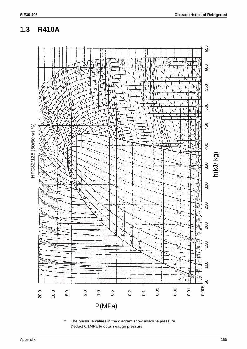
SiE30-408 Characteristics of Refrigerant
Appendix 195
1.3 R410A
* The pressure values in the diagram show absolute pressure.Deduct 0.1MPa to obtain gauge pressure.
HF
C32
/125
(50
/50
wt %
)
0.0007m³/kg
0.00075 m³/kg
0.00085m³/kg
0.00095 m³/k
g
0.0008 m³/kg
0.0009m³/kg
0.001 m³/k
g
0.00
2 m
³/kg
0.00
5 m
³/kg 0.01
m³/
kg
0.02
m³/
kg
0.05
m³/
kg
0.1
m³/
kg
0.2
m³/
kg
0.5
m³/
kg
1 m
³/kg
2 m
³/kg
5 m
³/kg
10 m
³/kg
0.00
110.
0012
0.00
130.
0014
0.00
15
0.1
0.2
0.3
0.4
0.5
0.6
0.7
0.8
0.9
1.0
0.6
0.7
0.8
1.0 kJ/(kg · K)
0.5 kJ/(kg · K)
2.0 kJ/(kg · K)
1.1
1.2
1.3
1.4
1.5
1.6
1.7
1.8
1.9
2.1
2.2
2.3
2.4
2.5
2.6
2.7
2.8
2.9
0.9
x = 0.0
20.
0
10.
0
5.
0
2.
0
1.
0
0.
5
0.
2
0.
1
0.
05
0.
02
0.
01
0.
005
5010
015
020
025
030
035
040
045
050
055
060
065
0
h(kJ
/ kg)
P(MPa)
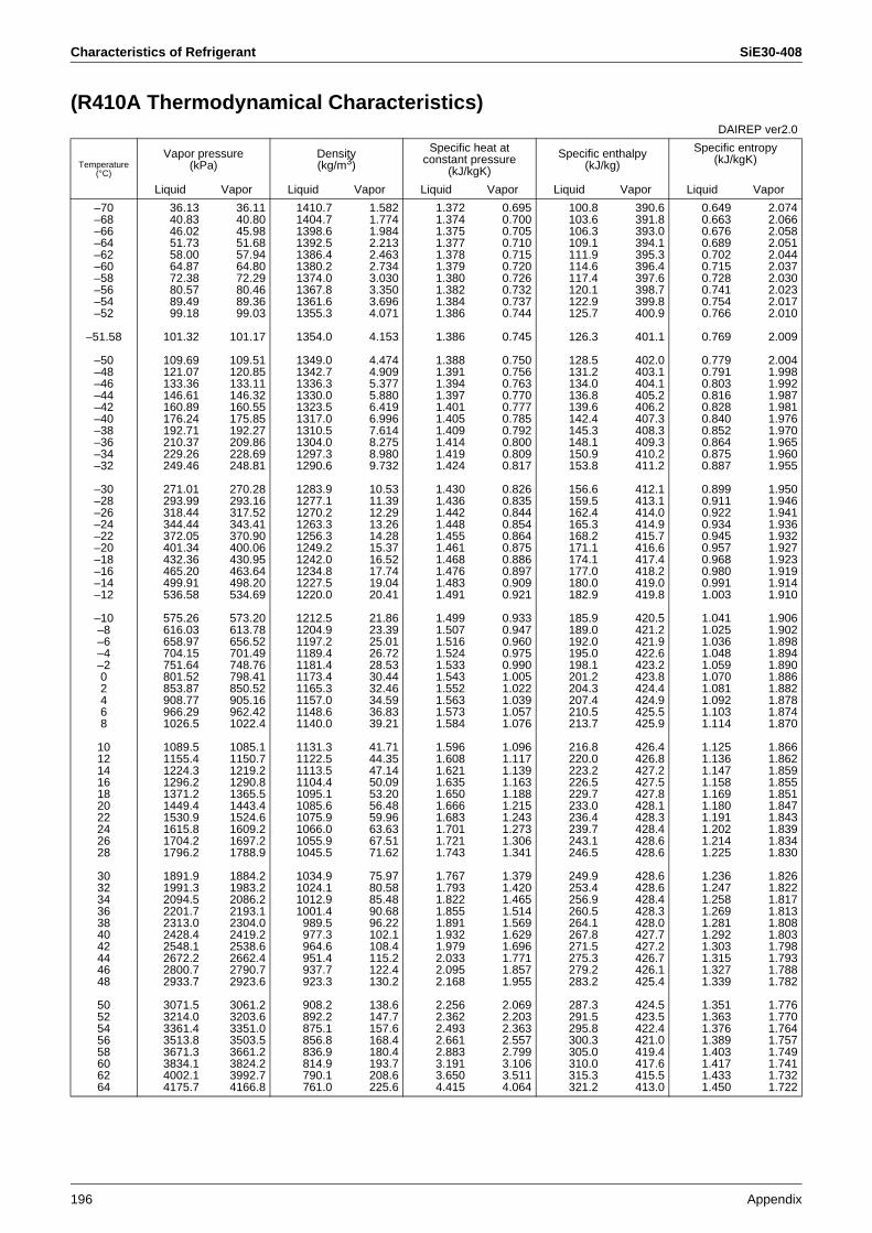
Characteristics of Refrigerant SiE30-408
196 Appendix
(R410A Thermodynamical Characteristics)DAIREP ver2.0
Temperature (°C)
Vapor pressure(kPa)
Density(kg/m3)
Specific heat at constant pressure
(kJ/kgK)
Specific enthalpy(kJ/kg)
Specific entropy(kJ/kgK)
Liquid Vapor Liquid Vapor Liquid Vapor Liquid Vapor Liquid Vapor
–70–68–66–64–62–60–58–56–54–52
–51.58
–50–48–46–44–42–40–38–36–34–32
–30–28–26–24–22–20–18–16–14–12
–10–8–6–4–202468
10121416182022242628
30323436384042444648
5052545658606264
36.1340.8346.0251.7358.0064.8772.3880.5789.4999.18
101.32
109.69121.07133.36146.61160.89176.24192.71210.37229.26249.46
271.01293.99318.44344.44372.05401.34432.36465.20499.91536.58
575.26616.03658.97704.15751.64801.52853.87908.77966.291026.5
1089.51155.41224.31296.21371.21449.41530.91615.81704.21796.2
1891.91991.32094.52201.72313.02428.42548.12672.22800.72933.7
3071.53214.03361.43513.83671.33834.14002.14175.7
36.1140.8045.9851.6857.9464.8072.2980.4689.3699.03
101.17
109.51120.85133.11146.32160.55175.85192.27209.86228.69248.81
270.28293.16317.52343.41370.90400.06430.95463.64498.20534.69
573.20613.78656.52701.49748.76798.41850.52905.16962.421022.4
1085.11150.71219.21290.81365.51443.41524.61609.21697.21788.9
1884.21983.22086.22193.12304.02419.22538.62662.42790.72923.6
3061.23203.63351.03503.53661.23824.23992.74166.8
1410.71404.71398.61392.51386.41380.21374.01367.81361.61355.3
1354.0
1349.01342.71336.31330.01323.51317.01310.51304.01297.31290.6
1283.91277.11270.21263.31256.31249.21242.01234.81227.51220.0
1212.51204.91197.21189.41181.41173.41165.31157.01148.61140.0
1131.31122.51113.51104.41095.11085.61075.91066.01055.91045.5
1034.91024.11012.91001.4
989.5977.3964.6951.4937.7923.3
908.2892.2875.1856.8836.9814.9790.1761.0
1.5821.7741.9842.2132.4632.7343.0303.3503.6964.071
4.153
4.4744.9095.3775.8806.4196.9967.6148.2758.9809.732
10.5311.3912.2913.2614.2815.3716.5217.7419.0420.41
21.8623.3925.0126.7228.5330.4432.4634.5936.8339.21
41.7144.3547.1450.0953.2056.4859.9663.6367.5171.62
75.9780.5885.4890.6896.22102.1108.4115.2122.4130.2
138.6147.7157.6168.4180.4193.7208.6225.6
1.3721.3741.3751.3771.3781.3791.3801.3821.3841.386
1.386
1.3881.3911.3941.3971.4011.4051.4091.4141.4191.424
1.4301.4361.4421.4481.4551.4611.4681.4761.4831.491
1.4991.5071.5161.5241.5331.5431.5521.5631.5731.584
1.5961.6081.6211.6351.6501.6661.6831.7011.7211.743
1.7671.7931.8221.8551.8911.9321.9792.0332.0952.168
2.2562.3622.4932.6612.8833.1913.6504.415
0.6950.7000.7050.7100.7150.7200.7260.7320.7370.744
0.745
0.7500.7560.7630.7700.7770.7850.7920.8000.8090.817
0.8260.8350.8440.8540.8640.8750.8860.8970.9090.921
0.9330.9470.9600.9750.9901.0051.0221.0391.0571.076
1.0961.1171.1391.1631.1881.2151.2431.2731.3061.341
1.3791.4201.4651.5141.5691.6291.6961.7711.8571.955
2.0692.2032.3632.5572.7993.1063.5114.064
100.8103.6106.3109.1111.9114.6117.4120.1122.9125.7
126.3
128.5131.2134.0136.8139.6142.4145.3148.1150.9153.8
156.6159.5162.4165.3168.2171.1174.1177.0180.0182.9
185.9189.0192.0195.0198.1201.2204.3207.4210.5213.7
216.8220.0223.2226.5229.7233.0236.4239.7243.1246.5
249.9253.4256.9260.5264.1267.8271.5275.3279.2283.2
287.3291.5295.8300.3305.0310.0315.3321.2
390.6391.8393.0394.1395.3396.4397.6398.7399.8400.9
401.1
402.0403.1404.1405.2406.2407.3408.3409.3410.2411.2
412.1413.1414.0414.9415.7416.6417.4418.2419.0419.8
420.5421.2421.9422.6423.2423.8424.4424.9425.5425.9
426.4426.8427.2427.5427.8428.1428.3428.4428.6428.6
428.6428.6428.4428.3428.0427.7427.2426.7426.1425.4
424.5423.5422.4421.0419.4417.6415.5413.0
0.6490.6630.6760.6890.7020.7150.7280.7410.7540.766
0.769
0.7790.7910.8030.8160.8280.8400.8520.8640.8750.887
0.8990.9110.9220.9340.9450.9570.9680.9800.9911.003
1.0411.0251.0361.0481.0591.0701.0811.0921.1031.114
1.1251.1361.1471.1581.1691.1801.1911.2021.2141.225
1.2361.2471.2581.2691.2811.2921.3031.3151.3271.339
1.3511.3631.3761.3891.4031.4171.4331.450
2.0742.0662.0582.0512.0442.0372.0302.0232.0172.010
2.009
2.0041.9981.9921.9871.9811.9761.9701.9651.9601.955
1.9501.9461.9411.9361.9321.9271.9231.9191.9141.910
1.9061.9021.8981.8941.8901.8861.8821.8781.8741.870
1.8661.8621.8591.8551.8511.8471.8431.8391.8341.830
1.8261.8221.8171.8131.8081.8031.7981.7931.7881.782
1.7761.7701.7641.7571.7491.7411.7321.722
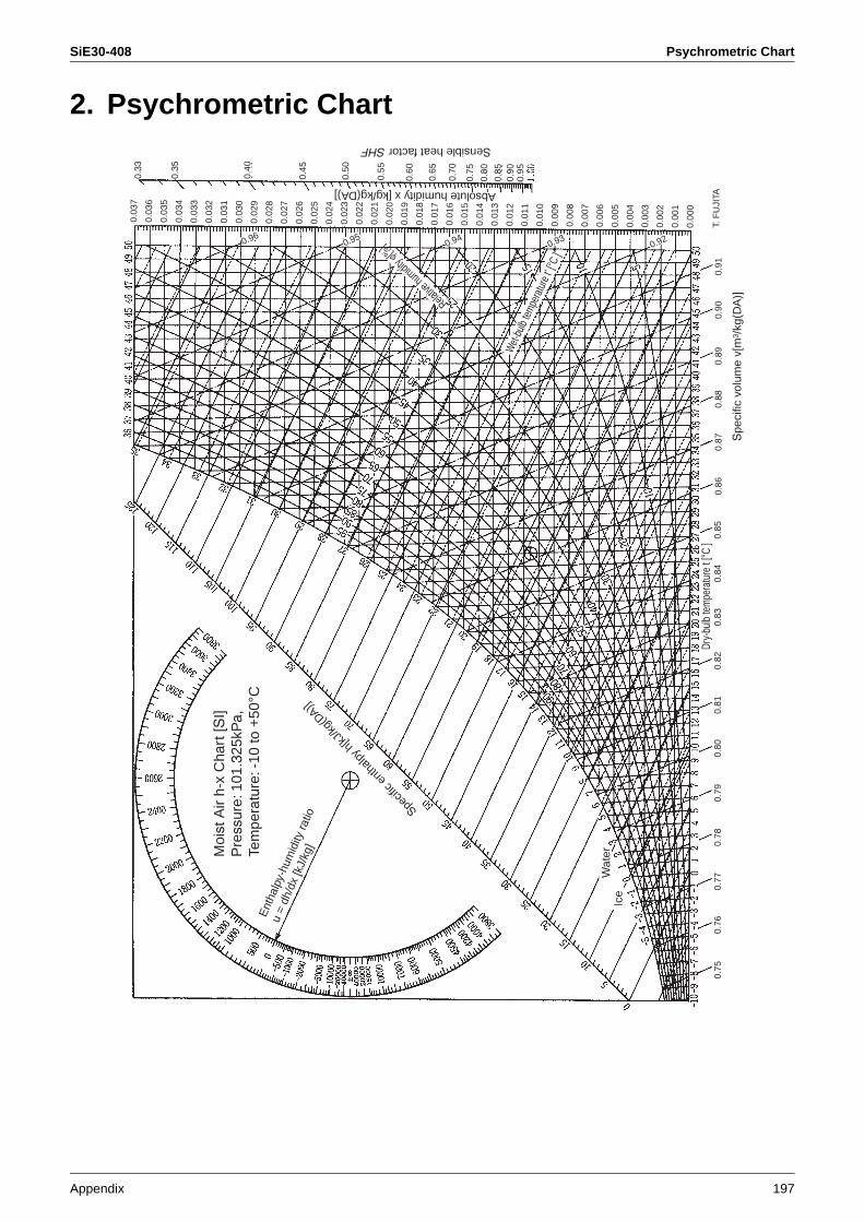
SiE30-408 Psychrometric Chart
Appendix 197
2. Psychrometric Chart
Dry-
bulb
tem
pera
ture
t [°C
]
Spe
cific
vol
ume
v[m
3 /kg
(DA
)]
Moi
st A
ir h-
x C
hart
[SI]
Pre
ssur
e: 1
01.3
25kP
a,Te
mpe
ratu
re: -
10 to
+50
°CE
ntha
lpy-
hum
idity
ratio
u =
dh/d
x [k
J/kg
]
Specif
ic en
thalp
y h[kJ
/kg(D
A)]
Ice
Wat
er
Relative
humidit
yϕ[%]
Wet-
bulb
tempe
ratur
e t' [°
C ]
Absolute humidity x [kg/kg(DA)]
Sensible heat factorSHF
0.03
7
0.03
6
0.03
5
0.03
4
0.03
3
0.03
2
0.03
1
0.03
0
0.02
9
0.02
8
0.02
7
0.02
6
0.02
5
0.02
4
0.02
3
0.02
2
0.02
1
0.02
0
0.01
9
0.01
8
0.01
7
0.01
6
0.01
5
0.01
4
0.01
3
0.01
2
0.01
1
0.01
0
0.00
9
0.00
8
0.00
7
0.00
6
0.00
5
0.00
4
0.00
3
0.00
2
0.00
1
0.00
0
0.33
0.960.95
0.940.93
0.92
0.35
0.40
0.45
0.50
0.55
0.60
0.65
0.70
0.75
0.80
0.85
0.90
0.95
0.75
0.76
0.77
0.78
0.79
0.80
0.81
0.82
0.83
0.84
0.85
0.86
0.87
0.88
0.89
0.90
0.91
T. F
UJI
TA

How to Calculate Cooling / Heating Capacity SiE30-408
198 Appendix
3. How to Calculate Cooling / Heating CapacityMeasure the temperatures of suction air and discharge air of indoor unit. Then, calculate the capacity by using the psychrometric chart.
How to calculate the cooling capacity
How to calculate the heating capacity
Example for cooling capacity calculationSuction air. . . . . . Dry-bulb temperature: 30°C Wet-bulb temperature: 24°CDischarge air. . . . Dry-bulb temperature: 20°C Wet-bulb temperature: 18.5°CAir flow rate. . . . . 800 m3/h
According to the psychrometric chart, following values are obtained.Enthalpy of suction air: 72.7 kJ/kgEnthalpy of discharge air: 52.9 kJ/kgSpecific volume of discharge air: 0.85 m3/kgCooling capacity is obtained by substituting those values to the above calculation formula.
Specific volume of discharge air 3600Cooling capacity = (Enthalpy of suction air – Enthalpy of discharge air) × × Air flow rate ×1 1
(kW) (kJ/kg) (kJ/kg) (kg/m3) (m3/h)
Cooling capacity = (72.7 – 52.9) ×0.85 3600
× 800 ×1 1= 5.18kW··
Example for heating capacity calculationSuction air temperature . . . . . 15°CDischarge air temperature . . . 45°CAir flow rate. . . . . . . . . . . . . . . 800 m3/h
According to the psychrometric chart, following value is obtained.Specific volume … 0.91 m3/kgHeating capacity is obtained by substituting those values to the above calculation formula.
Specific volume 3600Heating capacity = 1.00 × Discharge air temperature – Suction air temperature × Air flow rate × ×1 1
(kW) (kJ/kg · k) (°C) (°C) (kg/m3)(m3/h)
0.91 3600Heating capacity = 1.00 × (45 –15) × 800 × ×1 1
= 7.33kW
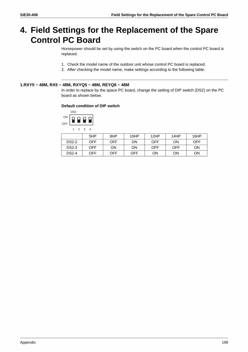
SiE30-408 Field Settings for the Replacement of the Spare Control PC Board
Appendix 199
4. Field Settings for the Replacement of the Spare Control PC Board
Horsepower should be set by using the switch on the PC board when the control PC board is replaced.
1. Check the model name of the outdoor unit whose control PC board is replaced.2. After checking the model name, make settings according to the following table.
1.RXY5 ~ 48M, RX5 ~ 48M, RXYQ5 ~ 48M, REYQ8 ~ 48MIn order to replace by the space PC board, change the setting of DIP switch (DS2) on the PC board as shown below.
Default condition of DIP switch
1 2 3 4
DS2
ON
OFF
5HP 8HP 10HP 12HP 14HP 16HP
DS2-2 OFF OFF ON OFF ON OFF
DS2-3 OFF ON ON OFF OFF ON
DS2-4 OFF OFF OFF ON ON ON

Field Settings for the Replacement of the Spare Control PC Board SiE30-408
200 Appendix
2. RSXYP5, 8, 10LIn order to replace by the space PC board, change the setting of DIP switch (DS1) on the PC board as shown below.
Default condition of DIP switch
3. RSXP16 ~ 30K, RSXYP16 ~ 30KJ, RSEYP16 ~ 30KJIn order to replace by the space PC board,, change the setting of DIP switches (SS2 to SS5) on the PC board as shown below.
Note: Resetting of power supply switch is neccessary after capacity setting.
5L 8L 10L
DS1-7 ON OFF ON
DS1-8 OFF ON ON
ON
OFF
1 2 3 4 5 6 7 8
DS1
SS2 SS3 SS4 SS5
A B C D E F G H
RSXYP16KJRSXP16K, RSEYP16KJ
RSXYP18KJRSXP18K, RSEYP18KJ
RSXYP20KJRSXP20K, RSEYP20KJ
RSXYP24KJRSXP24K, RSEYP24KJ
RSXYP26KJRSXP26K, RSEYP26KJ
RSXYP28KJRSXP28K, RSEYP28KJ
RSXYP30KJRSXP30K, RSEYP30KJ
Capacity setting table
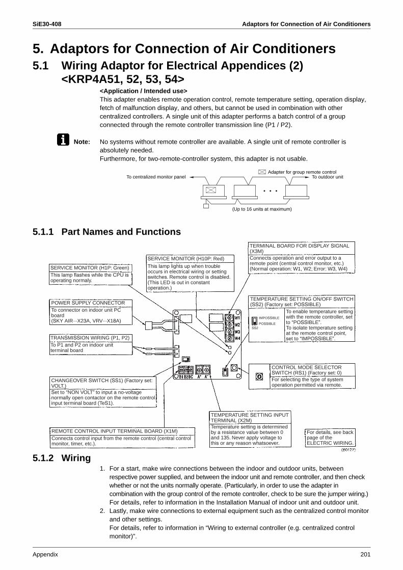
SiE30-408 Adaptors for Connection of Air Conditioners
Appendix 201
5. Adaptors for Connection of Air Conditioners5.1 Wiring Adaptor for Electrical Appendices (2)
<KRP4A51, 52, 53, 54><Application / Intended use>This adapter enables remote operation control, remote temperature setting, operation display, fetch of malfunction display, and others, but cannot be used in combination with other centralized controllers. A single unit of this adapter performs a batch control of a group connected through the remote controller transmission line (P1 / P2).
Note: No systems without remote controller are available. A single unit of remote controller is absolutely needed.Furthermore, for two-remote-controller system, this adapter is not usable.
5.1.1 Part Names and Functions
5.1.2 Wiring1. For a start, make wire connections between the indoor and outdoor units, between
respective power supplied, and between the indoor unit and remote controller, and then check whether or not the units normally operate. (Particularly, in order to use the adapter in combination with the group control of the remote controller, check to be sure the jumper wiring.)For details, refer to information in the Installation Manual of indoor unit and outdoor unit.
2. Lastly, make wire connections to external equipment such as the centralized control monitor and other settings.For details, refer to information in “Wiring to external controller (e.g. centralized control monitor)”.
(Up to 16 units at maximum)
Adapter for group remote controlTo outdoor unitTo centralized monitor panel
SERVICE MONITOR (H1P: Green)This lamp flashes while the CPU isoperating normaly.
TRANSMISSION WIRING (P1, P2)To P1 and P2 on indoor unitterminal board
REMOTE CONTROL INPUT TERMINAL BOARD (X1M)Connects control input from the remote control (central control monitor, timer, etc.).
POWER SUPPLY CONNECTORTo connector on indoor unit PC board(SKY AIR···X23A, VRV···X18A)
CHANGEOVER SWITCH (SS1) (Factory set: VOLT.)Set to “NON VOLT” to input a no-voltagenormally open contactor on the remote control input terminal board (TeS1).
TEMPERATURE SETTING INPUT TERMINAL (X2M)Temperature setting is determined by a resistance value between 0 and 135. Never apply voltage to this or any reason whatsoever.
For details, see back page of the ELECTRIC WIRING.
IMPOSSIBLE
POSSIBLESS2
TEMPERATURE SETTING ON/OFF SWITCH(SS2) (Factory set: POSSIBLE)
To enable temperature settingwith the remote controller, setto “POSSIBLE”.To isolate temperature settingat the remote control point, set to “IMPOSSIBLE”.
CONTROL MODE SELECTOR SWITCH (RS1) (Factory set: 0)For selecting the type of systemoperation permitted via remote.
TERMINAL BOARD FOR DISPLAY SIGNAL(X3M)Connects operation and error output to aremote point (central control monitor, etc.) (Normal operation: W1, W2; Error: W3, W4)
SERVICE MONITOR (H10P: Red)
This lamp lights up when troubleoccurs in electrical wiring or settingswitches. Remote control is disabled. (This LED is out in constantoperation.)
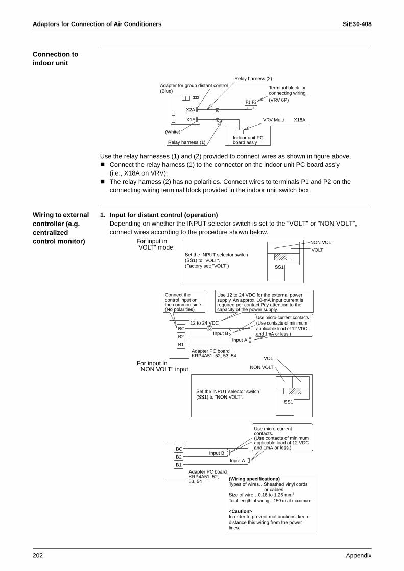
Adaptors for Connection of Air Conditioners SiE30-408
202 Appendix
Connection to indoor unit
Use the relay harnesses (1) and (2) provided to connect wires as shown in figure above.Connect the relay harness (1) to the connector on the indoor unit PC board ass'y (i.e., X18A on VRV).The relay harness (2) has no polarities. Connect wires to terminals P1 and P2 on the connecting wiring terminal block provided in the indoor unit switch box.
Wiring to external controller (e.g. centralized control monitor)
1. Input for distant control (operation)Depending on whether the INPUT selector switch is set to the “VOLT" or "NON VOLT”, connect wires according to the procedure shown below.
Relay harness (2)
Relay harness (1)
X2A
VRV Multi X18AX1A
P2P1
(White)Indoor unit PCboard ass'y
Adapter for group distant control (Blue)
Terminal block for connecting wiring (VRV 6P)
B2
BC
B1
Input A
G
Input B
B1
B2
BC
12 to 24 VDC
VOLT
SS1
SS1
NON VOLT
Connect the control input on the common side.(No polarities)
Use 12 to 24 VDC for the external power supply. An approx. 10-mA input current isrequired per contact.Pay attention to the capacity of the power supply.
Use micro-current contacts.(Use contacts of minimumapplicable load of 12 VDC and 1mA or less.)Input B
VOLT
NON VOLT
Use micro-currentcontacts.(Use contacts of minimumapplicable load of 12 VDC and 1mA or less.)
Input A
(Wiring specifications)Types of wires…Sheathed vinyl cords
or cablesSize of wire…0.18 to 1.25 mm2
Total length of wiring…150 m at maximum
<Caution>In order to prevent malfunctions, keep distance this wiring from the power lines.
For input in "VOLT" mode:
Set the INPUT selector switch(SS1) to "VOLT".(Factory set: "VOLT")
Adapter PC boardKRP4A51, 52, 53, 54
For input in "NON VOLT" input
Set the INPUT selector switch(SS1) to "NON VOLT".
Adapter PC boardKRP4A51, 52, 53, 54
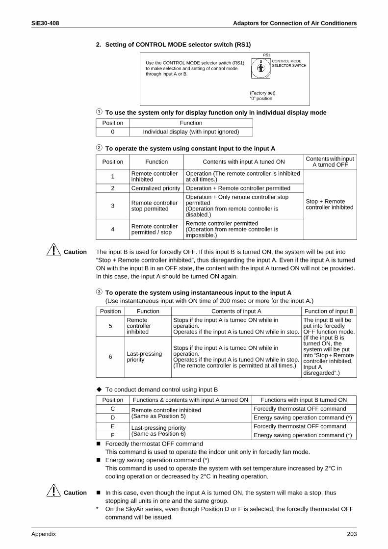
SiE30-408 Adaptors for Connection of Air Conditioners
Appendix 203
2. Setting of CONTROL MODE selector switch (RS1)
1 To use the system only for display function only in individual display mode
2 To operate the system using constant input to the input A
Caution The input B is used for forcedly OFF. If this input B is turned ON, the system will be put into “Stop + Remote controller inhibited”, thus disregarding the input A. Even if the input A is turned ON with the input B in an OFF state, the content with the input A turned ON will not be provided. In this case, the input A should be turned ON again.
3 To operate the system using instantaneous input to the input A(Use instantaneous input with ON time of 200 msec or more for the input A.)
To conduct demand control using input B
Forcedly thermostat OFF commandThis command is used to operate the indoor unit only in forcedly fan mode.Energy saving operation command (*)This command is used to operate the system with set temperature increased by 2°C in cooling operation or decreased by 2°C in heating operation.
Caution In this case, even though the input A is turned ON, the system will make a stop, thus stopping all units in one and the same group.
* On the SkyAir series, even though Position D or F is selected, the forcedly thermostat OFF command will be issued.
Position Function
0 Individual display (with input ignored)
Use the CONTROL MODE selector switch (RS1)to make selection and setting of control mode through input A or B.
(Factory set)“0” position
CONTROL MODE SELECTOR SWITCH
RS1
Position Function Contents with input A tuned ON Contents with input A turned OFF
1 Remote controller inhibited
Operation (The remote controller is inhibited at all times.)
Stop + Remote controller inhibited
2 Centralized priority Operation + Remote controller permitted
3 Remote controller stop permitted
Operation + Only remote controller stop permitted(Operation from remote controller is disabled.)
4 Remote controller permitted / stop
Remote controller permitted(Operation from remote controller is impossible.)
Position Function Contents of input A Function of input B
5Remotecontroller inhibited
Stops if the input A is turned ON while in operation.Operates if the input A is tuned ON while in stop.
The input B will be put into forcedly OFF function mode.(If the input B is turned ON, the system will be put into “Stop + Remote controller inhibited, Input A disregarded”.)
6 Last-pressingpriority
Stops if the input A is turned ON while in operation.Operates if the input A is tuned ON while in stop.(The remote controller is permitted at all times.)
Position Functions & contents with input A turned ON Functions with input B turned ON
C Remote controller inhibited (Same as Position 5)
Forcedly thermostat OFF command
D Energy saving operation command (*)
E Last-pressing priority(Same as Position 6)
Forcedly thermostat OFF command
F Energy saving operation command (*)
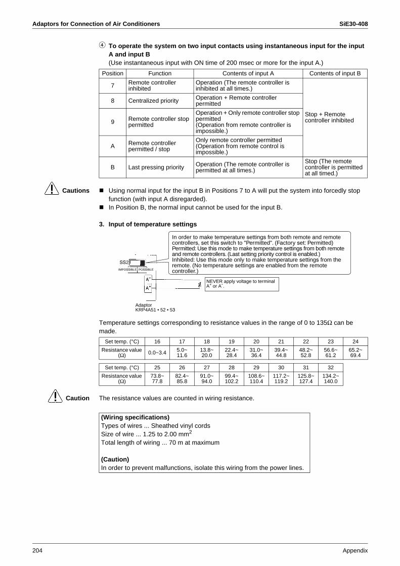
Adaptors for Connection of Air Conditioners SiE30-408
204 Appendix
4 To operate the system on two input contacts using instantaneous input for the input A and input B(Use instantaneous input with ON time of 200 msec or more for the input A.)
Cautions Using normal input for the input B in Positions 7 to A will put the system into forcedly stop function (with input A disregarded).In Position B, the normal input cannot be used for the input B.
3. Input of temperature settings
Temperature settings corresponding to resistance values in the range of 0 to 135Ω can be made.
Caution The resistance values are counted in wiring resistance.
Position Function Contents of input A Contents of input B
7 Remote controller inhibited
Operation (The remote controller is inhibited at all times.)
Stop + Remote controller inhibited
8 Centralized priority Operation + Remote controller permitted
9 Remote controller stop permitted
Operation + Only remote controller stop permitted(Operation from remote controller is impossible.)
A Remote controller permitted / stop
Only remote controller permitted(Operation from remote control is impossible.)
B Last pressing priority Operation (The remote controller is permitted at all times.)
Stop (The remote controller is permitted at all timed.)
In order to make temperature settings from both remote and remote controllers, set this switch to "Permitted". (Factory set: Permitted)Permitted: Use this mode to make temperature settings from both remote and remote controllers. (Last setting priority control is enabled.)Inhibited: Use this mode only to make temperature settings from the remote. (No temperature settings are enabled from the remote controller.)
NEVER apply voltage to terminalA+ or A-.
AdaptorKRP4A51 • 52 • 53
SS2IMPOSSIBLE POSSIBLE
Set temp. (°C) 16 17 18 19 20 21 22 23 24
Resistance value (Ω) 0.0~3.4 5.0~
11.613.8~20.0
22.4~28.4
31.0~36.4
39.4~44.8
48.2~52.8
56.6~61.2
65.2~69.4
Set temp. (°C) 25 26 27 28 29 30 31 32
Resistance value (Ω)
73.8~77.8
82.4~85.8
91.0~94.0
99.4~102.2
108.6~110.4
117.2~119.2
125.8~127.4
134.2~140.0
(Wiring specifications)Types of wires ... Sheathed vinyl cordsSize of wire ... 1.25 to 2.00 mm2
Total length of wiring ... 70 m at maximum
(Caution)In order to prevent malfunctions, isolate this wiring from the power lines.
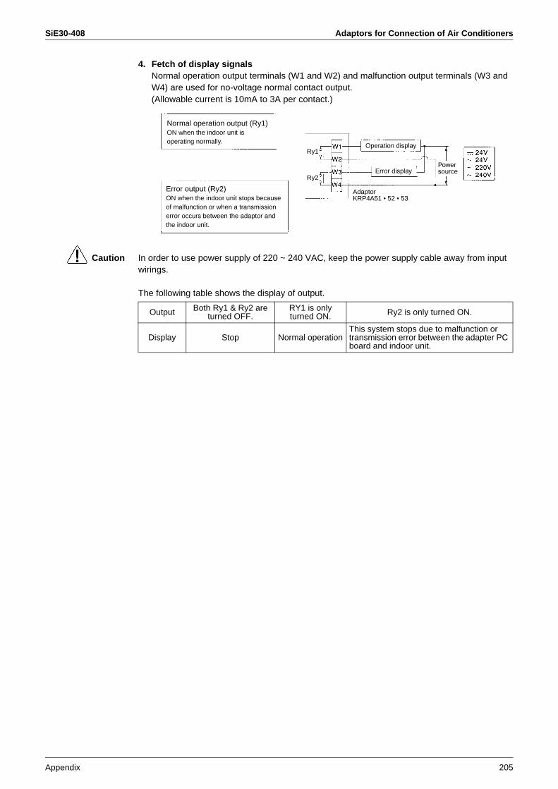
SiE30-408 Adaptors for Connection of Air Conditioners
Appendix 205
4. Fetch of display signalsNormal operation output terminals (W1 and W2) and malfunction output terminals (W3 and W4) are used for no-voltage normal contact output.(Allowable current is 10mA to 3A per contact.)
Caution In order to use power supply of 220 ~ 240 VAC, keep the power supply cable away from input wirings.
The following table shows the display of output.
AdaptorKRP4A51 • 52 • 53
Ry1Operation display
Error displayPower source
Ry2
Error output (Ry2)ON when the indoor unit stops becauseof malfunction or when a transmissionerror occurs between the adaptor andthe indoor unit.
Normal operation output (Ry1)ON when the indoor unit isoperating normally.
Output Both Ry1 & Ry2 are turned OFF.
RY1 is only turned ON. Ry2 is only turned ON.
Display Stop Normal operationThis system stops due to malfunction or transmission error between the adapter PC board and indoor unit.
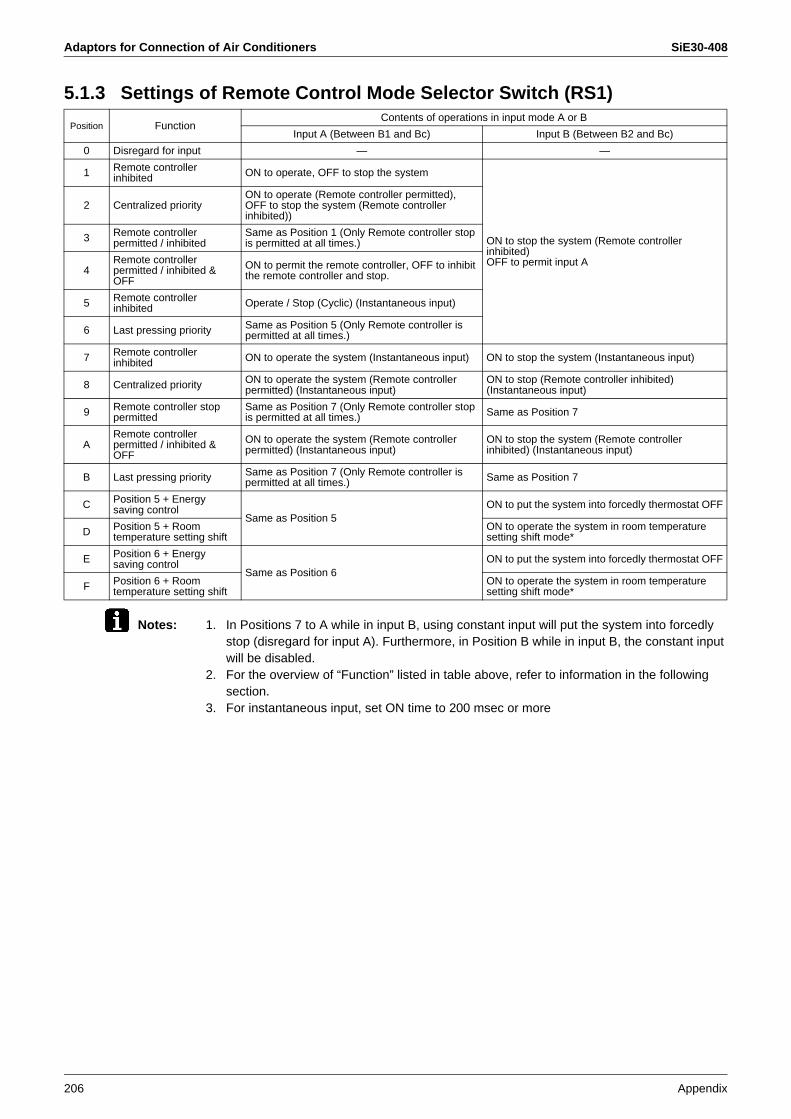
Adaptors for Connection of Air Conditioners SiE30-408
206 Appendix
5.1.3 Settings of Remote Control Mode Selector Switch (RS1)
Notes: 1. In Positions 7 to A while in input B, using constant input will put the system into forcedly stop (disregard for input A). Furthermore, in Position B while in input B, the constant input will be disabled.
2. For the overview of “Function” listed in table above, refer to information in the following section.
3. For instantaneous input, set ON time to 200 msec or more
Position FunctionContents of operations in input mode A or B
Input A (Between B1 and Bc) Input B (Between B2 and Bc)
0 Disregard for input — —
1 Remote controller inhibited ON to operate, OFF to stop the system
ON to stop the system (Remote controller inhibited)OFF to permit input A
2 Centralized priorityON to operate (Remote controller permitted), OFF to stop the system (Remote controller inhibited))
3 Remote controller permitted / inhibited
Same as Position 1 (Only Remote controller stop is permitted at all times.)
4Remote controller permitted / inhibited & OFF
ON to permit the remote controller, OFF to inhibit the remote controller and stop.
5 Remote controller inhibited Operate / Stop (Cyclic) (Instantaneous input)
6 Last pressing priority Same as Position 5 (Only Remote controller is permitted at all times.)
7 Remote controller inhibited ON to operate the system (Instantaneous input) ON to stop the system (Instantaneous input)
8 Centralized priority ON to operate the system (Remote controller permitted) (Instantaneous input)
ON to stop (Remote controller inhibited) (Instantaneous input)
9 Remote controller stop permitted
Same as Position 7 (Only Remote controller stop is permitted at all times.) Same as Position 7
ARemote controller permitted / inhibited & OFF
ON to operate the system (Remote controller permitted) (Instantaneous input)
ON to stop the system (Remote controller inhibited) (Instantaneous input)
B Last pressing priority Same as Position 7 (Only Remote controller is permitted at all times.) Same as Position 7
C Position 5 + Energy saving control
Same as Position 5ON to put the system into forcedly thermostat OFF
D Position 5 + Room temperature setting shift
ON to operate the system in room temperature setting shift mode*
E Position 6 + Energy saving control
Same as Position 6ON to put the system into forcedly thermostat OFF
F Position 6 + Room temperature setting shift
ON to operate the system in room temperature setting shift mode*
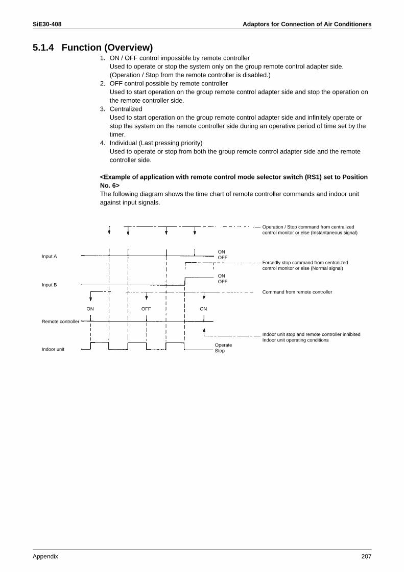
SiE30-408 Adaptors for Connection of Air Conditioners
Appendix 207
5.1.4 Function (Overview)1. ON / OFF control impossible by remote controller
Used to operate or stop the system only on the group remote control adapter side.(Operation / Stop from the remote controller is disabled.)
2. OFF control possible by remote controllerUsed to start operation on the group remote control adapter side and stop the operation on the remote controller side.
3. CentralizedUsed to start operation on the group remote control adapter side and infinitely operate or stop the system on the remote controller side during an operative period of time set by the timer.
4. Individual (Last pressing priority)Used to operate or stop from both the group remote control adapter side and the remote controller side.
<Example of application with remote control mode selector switch (RS1) set to Position No. 6>The following diagram shows the time chart of remote controller commands and indoor unit against input signals.
Input A
Input B
Remote controller
Indoor unit
ON ONOFF
Command from remote controller
Operation / Stop command from centralized control monitor or else (Instantaneous signal)
Forcedly stop command from centralized control monitor or else (Normal signal)
OperateStop
ONOFF
ONOFF
Indoor unit stop and remote controller inhibitedIndoor unit operating conditions

Adaptors for Connection of Air Conditioners SiE30-408
208 Appendix
5.1.5 Combined use with Centralized ControllersThe combined use of the wiring adaptor for electrical appendices (2) and the centralized controllers is enabled by the setting method shown below under the limited conditions.
Setting method Cut the spare jumper (J5) connected to wiring adaptor for electrical appendices (2). (If the use conditions shown below are not satisfied, however, the adapter may not normally function.)
Use conditions 1. If the wiring adaptor for electrical appendices (2) is used by following methods, the combined use will be enabled.• Operation and malfunction with the wiring adaptor for electrical appendices (2)• Forcedly thermostat OFF control with the wiring adaptor for electrical appendices (2)
(For mode settings, only use the input B in Positions C and E.)• Temperature setting shift control with the wiring adaptor for electrical appendices (2)
(For mode settings, only use the input B in Positions D and F. This control, however, is disabled in combined use with the temperature setting unit (DPF201A53).)
• The operation mode of the centralized controllers is set to "Individual (last pressing priority)" and the control mode of the wiring adaptor for electrical appendices (2) is also set to "Individual (last pressing priority)".
2. If the system is adaptable to telecommunication with the use of the wiring adaptor for electrical appendices (2) and further the centralized remote controllers are used by the methods listed in table below.
CN1
CN2
J5
W1
W2
W3
W4
B1 B2 BC A+ A-
Spare 1
Cut this jumper.
KRP4A51~54
To indoor unitVRV: X18
To terminal blocks(P1 and P2) of indoor unit
Model Conditions
Central remote controller(DCS302C61)
No forcedly stop input is used and further this controller is used in any of operation mode 6, 7, 16, and 17.
Unified ON / OFF controller(DCS301B61)
No forcedly stop input is used and further this controller is used in the operation mode set to “last pressing priority”.
Schedule timer(DST301B61) This timer used in operation code set to “last pressing priority”.
Unified adaptor for computerized control(DCS302A52)
This adapter is used in input mode set to Position 3.
Parallel interface Basic unit(DPF201A51)
No forcedly stop input is used and further this interface is used in operation mode set to Position 1.
Data station(DDS501A51)
No forcedly stop input is used and further no system forcedly stop command or remote controller inhibited command is used.

SiE30-408 Adaptors for Connection of Air Conditioners
Appendix 209
5.2 Wiring Adaptor for Electrical Appendices (1) (KRP2A61, 62)
Application / Intended use
This adapter enables remote operation control, remote temperature setting, operation display, fetch of malfunction display, and others, but cannot be used in combination with other centralized controllers.Since this adapter is connected to the centralized control line, “air conditioners, which are connected to the centralized control lines (F1 / F2), are all operated under unified control.”
Overview of system
Notes 1. Shaded area: Represents the wiring adaptor for electrical appendices (1).2. The wiring adaptor for electrical appendices (1) is used to "operate all indoor units
connected to the centralized control lines (i.e., terminals F1 and F2) under unified control". In other words, the said indoor units are all operated under one and the same control via the wiring adaptor for electrical appendices (1) from the centralized control monitor.
3. In order to operate the said indoor units under individual group control, use the wiring adaptor for electrical appendices (2) (KRP4A51, 52, 53, 54). The wiring adaptor for electrical appendices (1) is not available for this control.
5.2.1 Part Names and Functions
Outdoor unit
To outdoor unit
Indoor unit
Centralized control monitor
Wiring adaptor for electricalappendices (1)
Microcomputer normal monitor (HAP: GREEN)
Flickers when the microcomputer isoperating normally.
Display output terminal board (X2M)
Connects operation and error output to a remote point (host computer monitor panel, etc.). (Normaloperation: W1, W2; Malfunction: W3, W4)
Trouble monitor (H10P: RED)
Lights up when trouble occurs in electrical wiring or parts.Remote control is disabled.(LED is out in normal operation.)
Control mode selector switch (RS1)(Factory set: 0)
For selecting how to operate the system via remote.
Power supply connector (D1, D2)
To adapter power supply connector (X1BA) on indoor unit
Transmission wiring (F1, F2)
To F1 and F2 on indoor unit terminalboard
Input changeover switch (SS1) (Factory set: VOLT)
Set according to the type of input (voltage/non-voltage) sent to remote control inputterminal board (X1M)
Remote control inputterminal board (X1M)
Connects control input from remote (host computermonitor panel, timer, etc.).
Temperature setting input terminals (A+, A-)
Temperature setting is determined by aresistance value between 0 and 135.NEVER apply voltage to this terminal for any reason whatsoever.
For details,see the wiring diagram (rearsurface).
Temperature setting ON/OFF switch (SS2)(Factory set: P)
To enable temperature setting with the remote controller, set to “Inhibition”.To set temperature setting only by remote control, set to “Permission”.
Display output switch (SS3) (Factory set: Z)
To display all control units as unifiedzone, set to “Zone”.
(Factory set)
SS3
SS3Note: Do not set to “Individual”. This
will cause a system error (H10P flashes.)
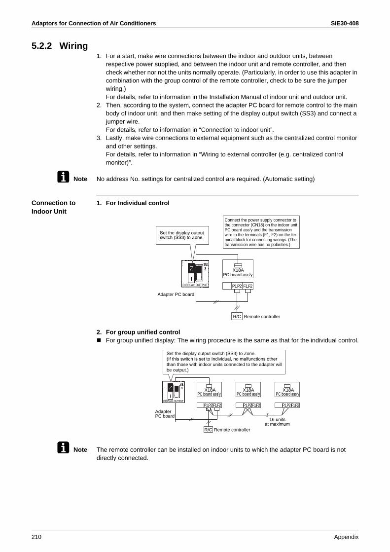
Adaptors for Connection of Air Conditioners SiE30-408
210 Appendix
5.2.2 Wiring1. For a start, make wire connections between the indoor and outdoor units, between
respective power supplied, and between the indoor unit and remote controller, and then check whether nor not the units normally operate. (Particularly, in order to use this adapter in combination with the group control of the remote controller, check to be sure the jumper wiring.)For details, refer to information in the Installation Manual of indoor unit and outdoor unit.
2. Then, according to the system, connect the adapter PC board for remote control to the main body of indoor unit, and then make setting of the display output switch (SS3) and connect a jumper wire.For details, refer to information in “Connection to indoor unit”.
3. Lastly, make wire connections to external equipment such as the centralized control monitor and other settings.For details, refer to information in “Wiring to external controller (e.g. centralized control monitor)”.
Note No address No. settings for centralized control are required. (Automatic setting)
Connection to Indoor Unit
1. For Individual control
2. For group unified controlFor group unified display: The wiring procedure is the same as that for the individual control.
Note The remote controller can be installed on indoor units to which the adapter PC board is not directly connected.
Adapter PC board
PC board ass'yX18A
P1,P2 F1,F2
Remote controllerR/C
Connect the power supply connector to the connector (CN18) on the indoor unitPC board ass'y and the transmissionwire to the terminals (F1, F2) on the ter-minal block for connecting wirings. (The transmission wire has no polarities.)
Set the display outputswitch (SS3) to Zone.
DISPLAY OUTPUT
PC board ass'y PC board ass'y PC board ass'yX18AX18AX18A
F1,F2F1,F2F1,F2P1,P2 P1,P2 P1,P2
Remote controllerR/C
Set the display output switch (SS3) to Zone.(If this switch is set to Individual, no malfunctions other than those with indoor units connected to the adapter will be output.)
AdapterPC board
16 unitsat maximum
DISPLAY OUTPUT

SiE30-408 Adaptors for Connection of Air Conditioners
Appendix 211
For individual display: The wiring procedure is the same as that for the individual control.
Note The remote controller can be installed on indoor units to which the adapter PC board is not directly connected.
3. For zone unified control: The wiring procedure is the same as that for the individual control.Be sure to set the display output switch (SS3) to Zone.
PC board ass'y PC board ass'yX18A
F1,F2P1,P2 P1,P2
SS3
Remote controllerR/C
RS1
X18A
F1,F2
0 Z
I
Display outputAdapter PC board
CONTROL MODE
AdapterPC board
16 unitsat maximum
Do not set the control mode selector switch (RS1)to Position 0. Not heeding this will not operate the system due to the malfunction of setting.
DISPLAY OUTPUT
SS3
Set the display outputswitch (SS3) to Individual.
DISPLAY OUTPUT
PC board ass'y PC board ass'y PC board ass'y
PC board ass'y
PC board ass'y
PC board ass'y PC board ass'y
Remote controller
Remote controller
Remote controller
X18AX18AX18A
F1,F2 P1,P2P1,P2P1,P2
X18AX18AX18A
P1,P2P1,P2P1,P2
P1,P2
F1,F2F1,F2
R/C
F1,F2F1,F2F1,F2
R/C
X18A
F1,F2
R/C
Note: For wire connections for centralized lines (F1, F2) to the indoor units, connect wires to any one of indoor units in one and the same group. (It is acceptable to connect wires to any indoor unit other than indoor units to which the remote controller is directly connected.)
(Wiring specifications)Types of wires...Sheathed vinyl cords or cables (2 cores)Size of wire...0.75 to 1.25 mm2
Total length of wiring...1000 m at maximum<Caution>In order to prevent malfunctions, keep awaythis wiring from the power lines.
DISPLAY OUTPUTDISPLAY OUTPUT
16 unitsat maximum
AdapterPC board
16 unitsat maximum
64 groupsat maximum

Adaptors for Connection of Air Conditioners SiE30-408
212 Appendix
Wiring to External Controller(e.g. Centralized Control Monitor)
1. Input for distant control (operation)Depending on whether the INPUT selector switch is set to the “Voltage” or “No-voltage”, connect wires according to the procedure shown below.
2. Setting of CONTROL MODE selector switch (RS1)Use the CONTROL MODE selector switch (RS1) on the adapter PC board to make selection and setting of control mode through input A or B.
1 To use the system only for display function only in individual display mode:
2 To operate the system using normal input to the input A
Position Function
0 Individual display (with input disregarded)
12 to 24 VDCGBC
B2
B1
BC
B2
B1
Input B
Input A
Input B
Input A
Set the INPUT selector switch(SS1) to "VOLT".(Factory set: "VOLT")
For input in "VOLT" mode:
Connect the control input on the common side.(No polarities)
Use 12 to 24 VDC for the external power supply.An approx. 10-mA input current is required by asingle contact.Pay attention to the capacity of the power supply.
Use micro-current contacts. (Use contactsof minimum applicable load of 12 VDC and1mA or less.)
Set the INPUT selectorswitch (SS1) to "NONE VOLT".
For input in "NONE VOLT" input
Use micro-current contacts. (Usecontacts of minimum applicable loadof 12 VDC and 1mA or less.)
(Wiring specifications)Types of wires...Sheathed wire Size of wire ...0.18 to 1.25 mm2
Total length of wiring...150 m at maximum<Caution>In order to prevent malfunctions, keep this wiring away from the power lines.
Adapter PC boardKRP2A61, 62, 51, 52
Adapter PC boardKRP2A61, 62, 51, 52
CHANGE OVER
CHANGE OVER
Factory set: “0” position
CO
NT
RO
L M
OD
E
RS1
Position Function Contents with input A tuned ON Contents with input A turned OFF
1 Remote controller inhibited
Operation (The remote controller is inhibited at all times.)
Stop + Remote controller inhibited
2 Centralized priority Operation + Remote controller permitted
3 Remote controller stop permitted
Operation + Only remote controller stop permitted(Operation from remote controller is impossible.)
4 Remote controller permitted / stop
Only remote controller permitted(Operation from remote is impossible.)
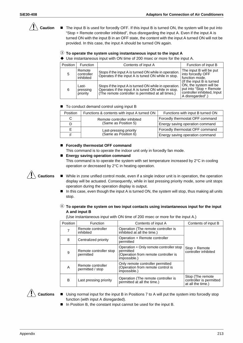
SiE30-408 Adaptors for Connection of Air Conditioners
Appendix 213
Caution The input B is used for forcedly OFF. If this input B is turned ON, the system will be put into “Stop + Remote controller inhibited”, thus disregarding the input A. Even if the input A is turned ON with the input B in an OFF state, the content with the input A turned ON will not be provided. In this case, the input A should be turned ON again.
3 To operate the system using instantaneous input to the input AUse instantaneous input with ON time of 200 msec or more for the input A.
To conduct demand control using input B
Forcedly thermostat OFF commandThis command is to operate the indoor unit only in forcedly fan mode.Energy saving operation commandThis command is to operate the system with set temperature increased by 2°C in cooling operation or decreased by 2°C in heating operation.
Cautions While in zone unified control mode, even if a single indoor unit is in operation, the operation display will be actuated. Consequently, while in last pressing priority mode, some unit stops operation during the operation display is output.In this case, even though the input A is turned ON, the system will stop, thus making all units stop.
4 To operate the system on two input contacts using instantaneous input for the input A and input B(Use instantaneous input with ON time of 200 msec or more for the input A.)
Cautions Using normal input for the input B in Positions 7 to A will put the system into forcedly stop function (with input A disregarded).In Position B, the constant input cannot be used for the input B.
Position Function Contents of input A Function of input B
5Remotecontroller inhibited
Stops if the input A is turned ON while in operation.Operates if the input A is tuned ON while in stop.
The input B will be put into forcedly OFF function mode.(If the input B is turned ON, the system will be put into “Stop + Remote controller inhibited, Input A disregarded”.)
6Last-pressingpriority
Stops if the input A is turned ON while in operation.Operates if the input A is tuned ON while in stop.(The remote controller is permitted at all times.)
Position Functions & contents with input A turned ON Functions with input B turned ON
C Remote controller inhibited(Same as Position 5)
Forcedly thermostat OFF command
D Energy saving operation command
E Last-pressing priority(Same as Position 6)
Forcedly thermostat OFF command
F Energy saving operation command
Position Function Contents of input A Contents of input B
7 Remote controller inhibited
Operation (The remote controller is inhibited at all the time.)
Stop + Remote controller inhibited
8 Centralized priority Operation + Remote controller permitted
9 Remote controller stop permitted
Operation + Only remote controller stop permitted(Operation from remote controller is impossible.)
A Remote controller permitted / stop
Only remote controller permitted(Operation from remote control is impossible.)
B Last pressing priority Operation (The remote controller is permitted at all the time.)
Stop (The remote controller is permitted at all the time.)
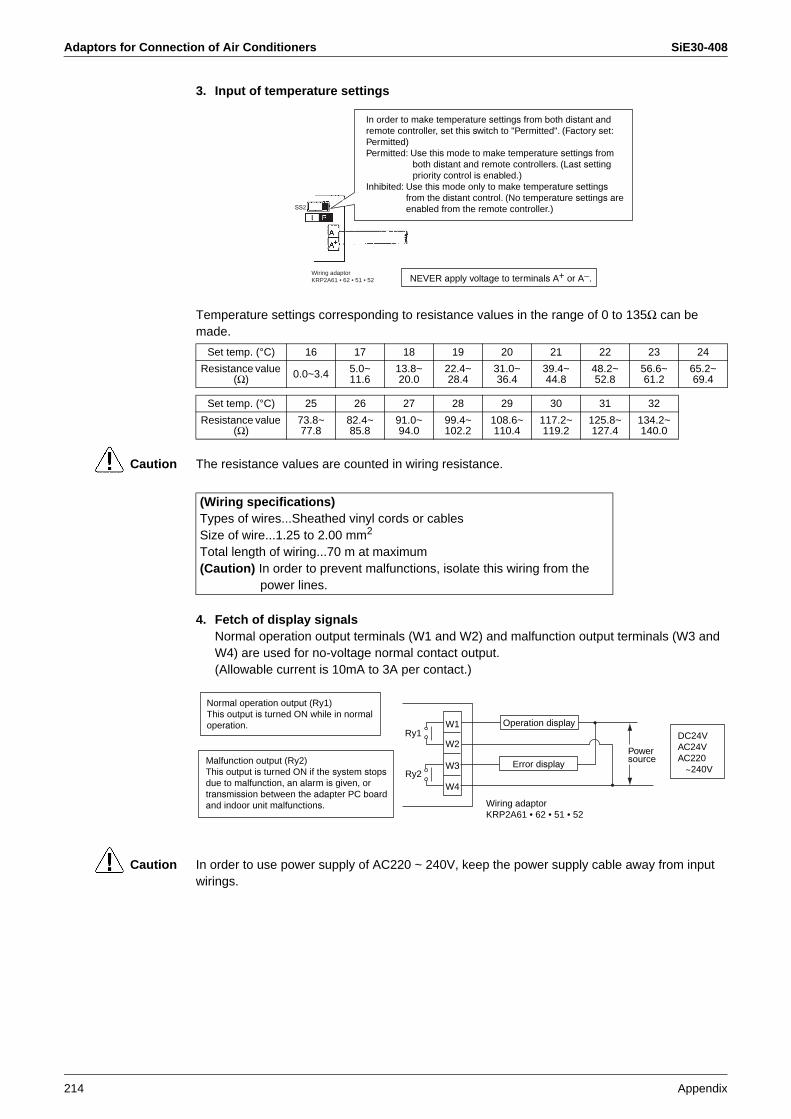
Adaptors for Connection of Air Conditioners SiE30-408
214 Appendix
3. Input of temperature settings
Temperature settings corresponding to resistance values in the range of 0 to 135Ω can be made.
Caution The resistance values are counted in wiring resistance.
4. Fetch of display signalsNormal operation output terminals (W1 and W2) and malfunction output terminals (W3 and W4) are used for no-voltage normal contact output.(Allowable current is 10mA to 3A per contact.)
Caution In order to use power supply of AC220 ~ 240V, keep the power supply cable away from input wirings.
In order to make temperature settings from both distant andremote controller, set this switch to "Permitted". (Factory set: Permitted)Permitted: Use this mode to make temperature settings from
both distant and remote controllers. (Last settingpriority control is enabled.)
Inhibited: Use this mode only to make temperature settingsfrom the distant control. (No temperature settings areenabled from the remote controller.)
NEVER apply voltage to terminals A+ or A−.Wiring adaptorKRP2A61 • 62 • 51 • 52
SS2
Set temp. (°C) 16 17 18 19 20 21 22 23 24
Resistance value (Ω) 0.0~3.4 5.0~
11.613.8~20.0
22.4~28.4
31.0~36.4
39.4~44.8
48.2~52.8
56.6~61.2
65.2~69.4
Set temp. (°C) 25 26 27 28 29 30 31 32
Resistance value (Ω)
73.8~77.8
82.4~85.8
91.0~94.0
99.4~102.2
108.6~110.4
117.2~119.2
125.8~127.4
134.2~140.0
(Wiring specifications)Types of wires...Sheathed vinyl cords or cablesSize of wire...1.25 to 2.00 mm2
Total length of wiring...70 m at maximum(Caution) In order to prevent malfunctions, isolate this wiring from the
power lines.
Normal operation output (Ry1)This output is turned ON while in normaloperation.
Malfunction output (Ry2)This output is turned ON if the system stopsdue to malfunction, an alarm is given, or transmission between the adapter PC boardand indoor unit malfunctions.
Ry1Operation display
Power source
DC24VAC24VAC220
~240VError display
Wiring adaptorKRP2A61 • 62 • 51 • 52
Ry2
W1
W2
W3
W4

SiE30-408 Adaptors for Connection of Air Conditioners
Appendix 215
The following table shows the output by system.
Caution If the wirings (F1, F2) are changed after the system operates once, apply power for a period of five minutes or more and then reset the power supply. No heeding so may disable the control from the wiring adaptor for electrical appendices (1).
Output
System
Both Ry1 & Ry2 are
turned OFF.
Only RY1 is turned ON. Only Ry2 is turned ON.
Individual control or individual display
Stop Normal operationThe system stops due to malfunction or malfunction of transmission between the adapter PC board and indoor unit .
Group unified control Stop All units are in
normal operation.
Even a single unit stops due to malfunction or malfunction of transmission between the adapter PC board and indoor unit.
Zone control All zones OFFAt least one unit running normally, no malfunction.
Even a single unit stops due to malfunction or malfunction of transmission between the adapter PC board and indoor unit.

Adaptors for Connection of Air Conditioners SiE30-408
216 Appendix
5.3 External Control Adaptor of Outdoor Unit <DTA104A53, 61, 62>
Application / Intended Use
This adapter is built in the indoor unit or BS unit connected through DIII-NET to select the operation mode (Cooling / Heating / Fan operation) in a batch on multiple outdoor units.
Overview of System
1. Batch selection of operation mode (Cooling / Heating / Fan operation)For selection of operation mode, using the indoor unit remote controller or cooling / heating selector remote controller(Possible only if outdoor units is RSX(Y) - KY1 • YAL • TAL type.)
2. Demand control / Low noise control(Possible only if outdoor units is RSX(Y) - KY1 • YAL • TAL type.)
External control adapter of outdoor unit
Indoor unit remote controller
Cooling / heating
selectorrem
ote controller
This mode enables a batch selection of operationmode of outdoor units enclosed with .
BS unit
This mode enables a batch of the demand control and the low noisecontrol of outdoor units enclosed with .

SiE30-408 Adaptors for Connection of Air Conditioners
Appendix 217
5.3.1 Part Names and Functions
5.3.2 Wiring1. Connect the power supply cable coming from this adapter to the adapter power supply
connector on the PC board of the outdoor unit, indoor unit, or BS unit.2. Connect the connecting wires to each terminal block, and terminals F1 and F2 on the PC
board as shown in figure below. (Use 2-core wires. No polarities.)3. For the connecting wires, use wiring ties provided and tie them to low voltage wires or else in
the switch box.
Notes: In order to built this adapter in the BS unit, connect wires between the “F1 and F2 on the indoor unit side” of the BS unit and the “F1 and F2” of the adapter.Tie the lead wires and connecting wires of this adapter so that these wires will not come into contact with the lid of the switch box.
Power supply connector (D1,D2)
Don't move it.
SS1
SS2
To adaptor power supply connector on indoor unit or BS unit
Function switch (SS1) (Factory set: On)
The contents of the address setting switch set the COOL/ HEAT address, demand address, or both addresses.
Microcomputer normal monitor (HAP: GRN)Flickers when the microcomputer is operating normally.
For details, see the wiring diagram (rear surface).
Address setting switch (DS1,2)Sets cool/heat address or demand address.
Demand, low-noise input terminal block (XIM)
Connects control input from electrical appendices (host computer monitor panel, demand controller, timer, ect.).
Terminal block for transmission (F1, F2)
Seeing wiring method.
F2F1
F2F1
IN - OUT
(Note 1)
Switch boxOutdoor unitPC board
orIndoor unitPC board
orBS unit PC board
External control adapter of outdoor unit
Adapter power supply connectorTerminal
block

Adaptors for Connection of Air Conditioners SiE30-408
218 Appendix
Cautions • Specifications of connecting wiresSheathed wire (2 wire) of 0.75 to 1.25 mm2 in size
• Length of connecting wiringsBe sure to observe the following limits. Not heeding so may result in the malfunction of transmission.
Total wiring length: 2000 m or lessMaximum numbers of branches: 16 branches
4. In order to perform input for the demand/low noise control, connect to the terminal block of this adapter.
Demand input terminalsShort circuit between (Demand 1) and (C)...Reducing power consumption to approx. 70% as a guideShort circuit between (Demand 2) and (C)...Reducing power consumption to approx. 40% as a guide.Short circuit between (Demand 3) and (C)...Forced thermostat OFF
Low noise input terminalsShort-circuiting between terminals saves capacity control (i.e., control of outdoor unit fan low-speed rotation or operating frequency of compressor) in cooling operation.Use these terminals only with a low level of load at nighttime.
Notes: In order to input the demand/low noise control, use the switch on the outdoor unit PC board to set mode to low noise control “YES”.
1. Outdoor unit field setting• Setting mode 1...Turn ON low noise control as explained in the outdoor unit’s service
manual.• Setting mode 2...Match low noise and demand addresses to the external control adapter
address.2. External control adapter settings
• Function switch (SS1)Set SS1 to either “BOTH“ or “DE“.
• Address setting switch (DS1, DS2)Match DS1 and DS2 to the low noise and demand addresses of outdoor unit.
2
P2
3 C
F1F2P1
1Demand
Host computer monitor panel or demand controller
(Input signal)Normally open contactAn approx. 10-mA input current is required per contact.Use micro-current contacts for relay contacts.
(Specifications of outside wirings)Recommended electric wires: Sheathed vinyl cords or cables 0.75 to 2m2
Wiring length: Within 150 mIn order to prevent malfunctions, keep this wiring a minimum 50 mm awayfrom the power lines.
To external control adapterof other outdoor units
Outside wiring indicatedby dotted line.
Low noise
How to set demand control in the field
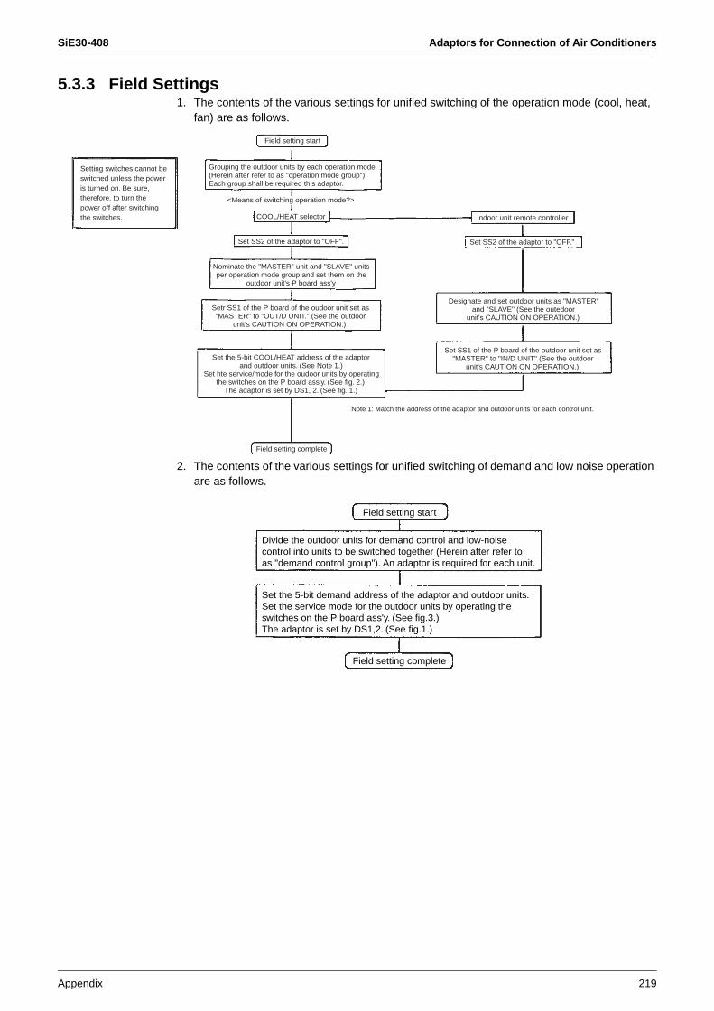
SiE30-408 Adaptors for Connection of Air Conditioners
Appendix 219
5.3.3 Field Settings1. The contents of the various settings for unified switching of the operation mode (cool, heat,
fan) are as follows.
2. The contents of the various settings for unified switching of demand and low noise operation are as follows.
Field setting start
Grouping the outdoor units by each operation mode. (Herein after refer to as "operation mode group"). Each group shall be required this adaptor.
<Means of switching operation mode?>
COOL/HEAT selector Indoor unit remote controller
Set SS2 of the adaptor to "OFF."
Designate and set outdoor units as "MASTER" and "SLAVE" (See the outedoor
unit's CAUTION ON OPERATION.)
Set SS1 of the P board of the outdoor unit set as "MASTER" to "IN/D UNIT" (See the outdoor
unit's CAUTION ON OPERATION.)
Note 1: Match the address of the adaptor and outdoor units for each control unit.
Set SS2 of the adaptor to "OFF".
Nominate the "MASTER" unit and "SLAVE" units per operation mode group and set them on the
outdoor unit's P board ass'y
Setting switches cannot be switched unless the power is turned on. Be sure, therefore, to turn the power off after switching the switches.
Setr SS1 of the P board of the oudoor unit set as "MASTER" to "OUT/D UNIT." (See the outdoor
unit's CAUTION ON OPERATION.)
Field setting complete
Set the 5-bit COOL/HEAT address of the adaptorand outdoor units. (See Note 1.)
Set hte service/mode for the oudoor units by operating the switches on the P board ass'y. (See fig. 2.)
The adaptor is set by DS1, 2. (See fig. 1.)
Divide the outdoor units for demand control and low-noise control into units to be switched together (Herein after refer to as "demand control group"). An adaptor is required for each unit.
Field setting start
Field setting complete
Set the 5-bit demand address of the adaptor and outdoor units.Set the service mode for the outdoor units by operating the switches on the P board ass'y. (See fig.3.)The adaptor is set by DS1,2. (See fig.1.)
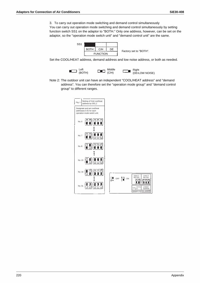
Adaptors for Connection of Air Conditioners SiE30-408
220 Appendix
3. To carry out operation mode switching and demand control simultaneouslyYou can carry out operation mode switching and demand control simultaneously by setting function switch SS1 on the adaptor to "BOTH." Only one address, however, can be set on the adaptor, so the "operation mode switch unit" and "demand control unit" are the same.
Set the COOL/HEAT address, demand address and low noise address, or both as needed.
Note 2: The outdoor unit can have an independent "COOL/HEAT address" and "demand address". You can therefore set the "operation mode group" and "demand control group" to different ranges.
Factory set to "BOTH".
SS1
BOTH C/H DE
FUNCTION
Left(BOTH)
Middle(C/H)
Right(DE•LOW NOISE)
Fig. 1
No. 0
No. 7
No. 8
No. 15
No. 16
No. 31
: OFF : ON
C/H
DEMAND CONTROL ADRESS
Setting of 5-bit cool/heataddress by DS1,2
Designate and set cool/heataddresses 0-31 for eachoperation mode switch unit.
Upper 2 bits DS2
Lower 3bits DS1
CENTRALNO.
LOWER ADRESS
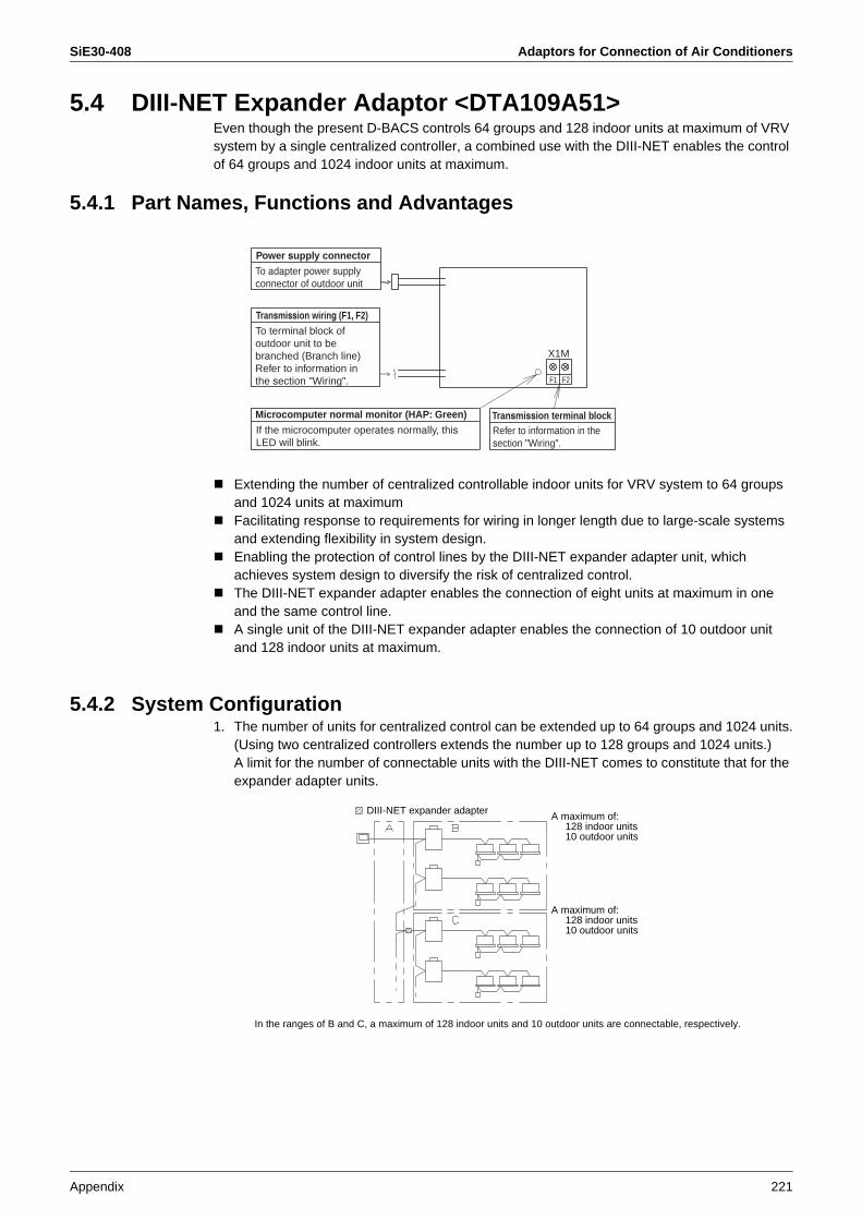
SiE30-408 Adaptors for Connection of Air Conditioners
Appendix 221
5.4 DIII-NET Expander Adaptor <DTA109A51>Even though the present D-BACS controls 64 groups and 128 indoor units at maximum of VRV system by a single centralized controller, a combined use with the DIII-NET enables the control of 64 groups and 1024 indoor units at maximum.
5.4.1 Part Names, Functions and Advantages
Extending the number of centralized controllable indoor units for VRV system to 64 groups and 1024 units at maximumFacilitating response to requirements for wiring in longer length due to large-scale systems and extending flexibility in system design.Enabling the protection of control lines by the DIII-NET expander adapter unit, which achieves system design to diversify the risk of centralized control.The DIII-NET expander adapter enables the connection of eight units at maximum in one and the same control line.A single unit of the DIII-NET expander adapter enables the connection of 10 outdoor unit and 128 indoor units at maximum.
5.4.2 System Configuration1. The number of units for centralized control can be extended up to 64 groups and 1024 units.
(Using two centralized controllers extends the number up to 128 groups and 1024 units.)A limit for the number of connectable units with the DIII-NET comes to constitute that for the expander adapter units.
In the ranges of B and C, a maximum of 128 indoor units and 10 outdoor units are connectable, respectively.
F1 F2
X1M
Power supply connectorTo adapter power supplyconnector of outdoor unit
Transmission wiring (F1, F2)To terminal block of outdoor unit to bebranched (Branch line)Refer to information in the section "Wiring".
Microcomputer normal monitor (HAP: Green)If the microcomputer operates normally, thisLED will blink.
Transmission terminal blockRefer to information in the section "Wiring".
DIII-NET expander adapter A maximum of: 128 indoor units 10 outdoor units
A maximum of: 128 indoor units 10 outdoor units
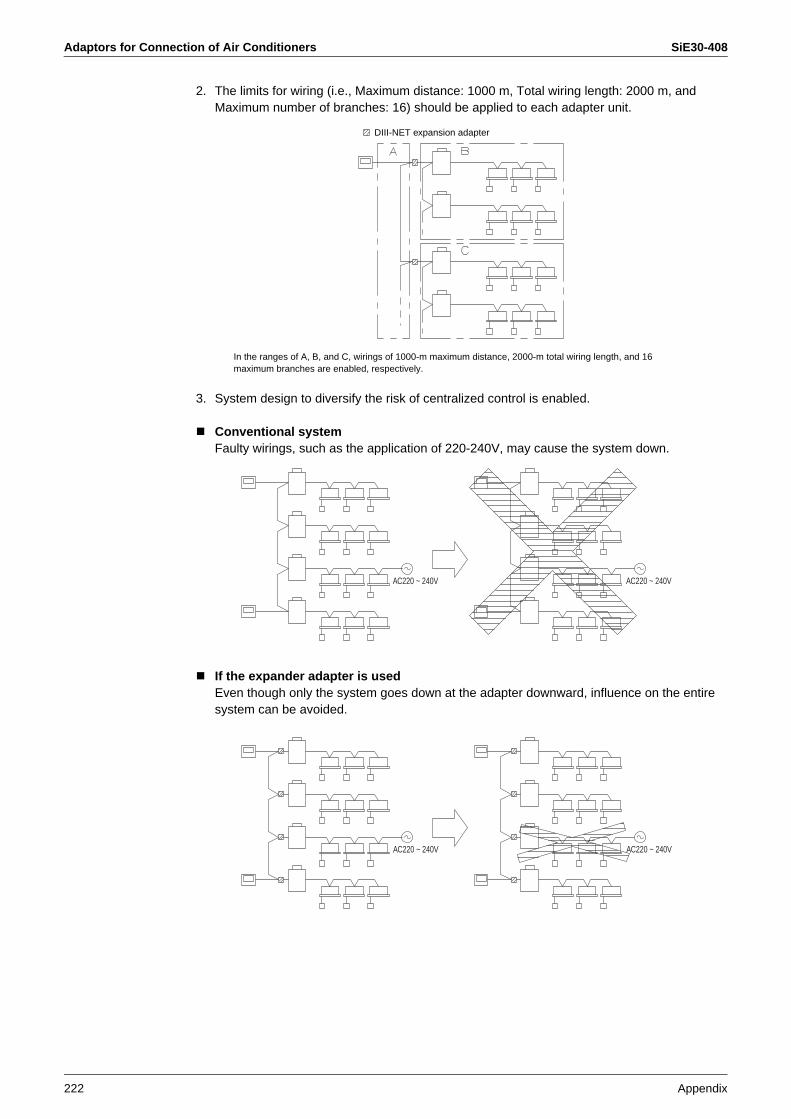
Adaptors for Connection of Air Conditioners SiE30-408
222 Appendix
2. The limits for wiring (i.e., Maximum distance: 1000 m, Total wiring length: 2000 m, and Maximum number of branches: 16) should be applied to each adapter unit.
In the ranges of A, B, and C, wirings of 1000-m maximum distance, 2000-m total wiring length, and 16 maximum branches are enabled, respectively.
3. System design to diversify the risk of centralized control is enabled.
Conventional systemFaulty wirings, such as the application of 220-240V, may cause the system down.
If the expander adapter is usedEven though only the system goes down at the adapter downward, influence on the entire system can be avoided.
DIII-NET expansion adapter
AC220 ~ 240V AC220 ~ 240V
AC220 ~ 240V AC220 ~ 240V
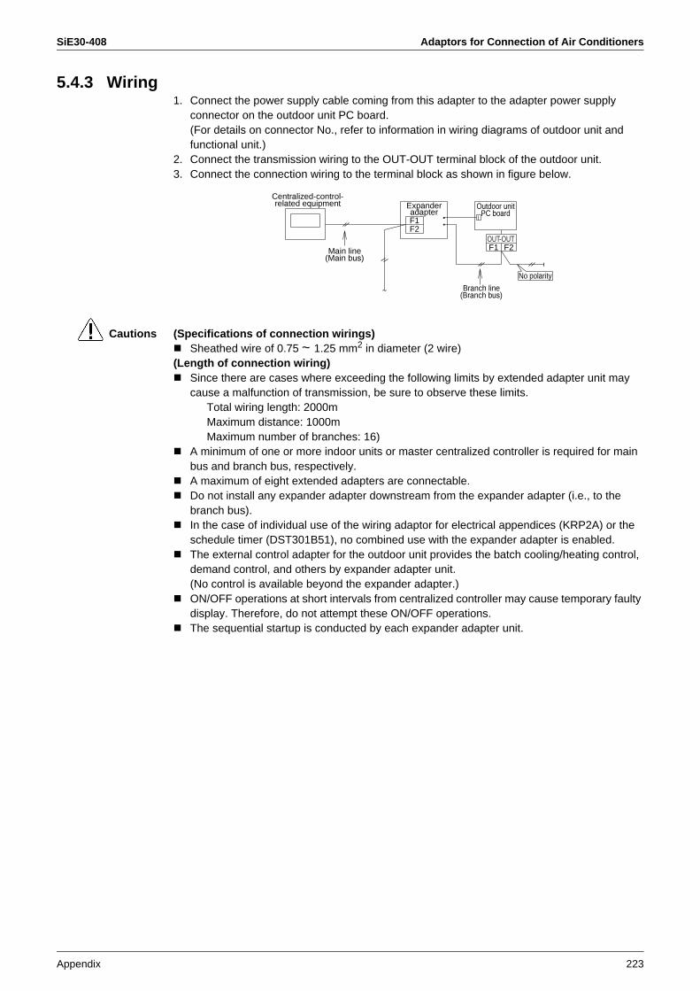
SiE30-408 Adaptors for Connection of Air Conditioners
Appendix 223
5.4.3 Wiring1. Connect the power supply cable coming from this adapter to the adapter power supply
connector on the outdoor unit PC board.(For details on connector No., refer to information in wiring diagrams of outdoor unit and functional unit.)
2. Connect the transmission wiring to the OUT-OUT terminal block of the outdoor unit.3. Connect the connection wiring to the terminal block as shown in figure below.
Cautions (Specifications of connection wirings)Sheathed wire of 0.75 ~ 1.25 mm2 in diameter (2 wire)
(Length of connection wiring)Since there are cases where exceeding the following limits by extended adapter unit may cause a malfunction of transmission, be sure to observe these limits.
Total wiring length: 2000mMaximum distance: 1000mMaximum number of branches: 16)
A minimum of one or more indoor units or master centralized controller is required for main bus and branch bus, respectively.A maximum of eight extended adapters are connectable.Do not install any expander adapter downstream from the expander adapter (i.e., to the branch bus).In the case of individual use of the wiring adaptor for electrical appendices (KRP2A) or the schedule timer (DST301B51), no combined use with the expander adapter is enabled.The external control adapter for the outdoor unit provides the batch cooling/heating control, demand control, and others by expander adapter unit.(No control is available beyond the expander adapter.)ON/OFF operations at short intervals from centralized controller may cause temporary faulty display. Therefore, do not attempt these ON/OFF operations.The sequential startup is conducted by each expander adapter unit.
F1
F1
F2
F2OUT-OUT
No polarity
~
~
Centralized-control-related equipment Expander
adapterOutdoor unit
PC board
Branch line (Branch bus)
Main line (Main bus)

Adaptors for Connection of Air Conditioners SiE30-408
224 Appendix
Example of Wiring
Wiring for system with 10 or more outdoor units
Caution Each range of A and B is individually subject to restrictions on the connection wiring length. (Refer to information in section “Wiring”.)
1 unit
2 units
10 units
A
B
··
··
··
··
F1F2
F1F2
IN-OUTIN-OUT
F1F2
F1F2
IN-OUTIN-OUT
F1F2
IN-OUT
F1F2
OUT-OUT
F1F2
OUT-OUTF1F2
IN-OUT
F1F2
IN-OUT
F1F2
IN-OUT
F1F2
Expanderadapter

SiE30-408 Adaptors for Connection of Air Conditioners
Appendix 225
5.5 Versatile Usage
Versatile Usage 1. Diversification of risk of centralized control systemThe DIII-NET extended adapter is originally designed to extend the system. In this connection, according to the usage shown in figure below, it is possible to design the centralized control system so that the system risk will be diversified.
Conventional systemFaulty wirings, such as the application of 200V, may cause the system down.
If the extended adapter is usedEven though only the system goes down at the adapter downward, influence on the entire system can be avoided.
AC220 ~ 240V AC220 ~ 240V
AC220 ~ 240V AC220 ~ 240V
: Expander adapters

Adaptors for Connection of Air Conditioners SiE30-408
226 Appendix
2. Relaxation of restrictions on branching DIII-NETWith the DIII-NET adapter, no secondary branching is enabled. Using expander adapters, however, enables branching shown in figure below. (Direct branching from the main line is referred to as the primary branching, and further branching from the primary branching is referred to as the secondary branching.)
Note:
This can be omitted.
: Expander adapter
Conventional system If the expander adapter is used
: Main line
: Primary branch line
: Secondary branch line
Centralized controller
Centralized controller

SiE30-408 Adaptors for Connection of Air Conditioners
Appendix 227
3. Method of extending systemUsing two units of expander adapters enables the connection of a maximum of 30 outdoor units (of 300 HP or less). An example of connection is shown in figure below.
Note: If additional extended adapters should be installed due to expansion or else after wires are connected as shown below, a significant change of the wiring within the system will be needed. Therefore, if any expansion is scheduled, follow an example of basic wiring shown in figure below.
Example of basic wiring
Even though there are several restrictions on the use of expander adapters, these restrictions can be relaxed by cutting jumper wires.
Cut the jumper wire “J2”. → The use of expander adapter in combination with thermal storage controller will be enabled.Cut the jumper wire “J3”. → The use of expander adapter in combination with external control adapter for outdoor unit will be enabled.
1 unit
10 units
··
··
··
1 unit
10 units
··
··
··
1 unit
10 units
··
··
··
Note:
The wiringis branched
off intotwo systems.
: Main bus
: Branch bus
J4 J3 J2 J1
Cut jumper wires at both sides in two locations.
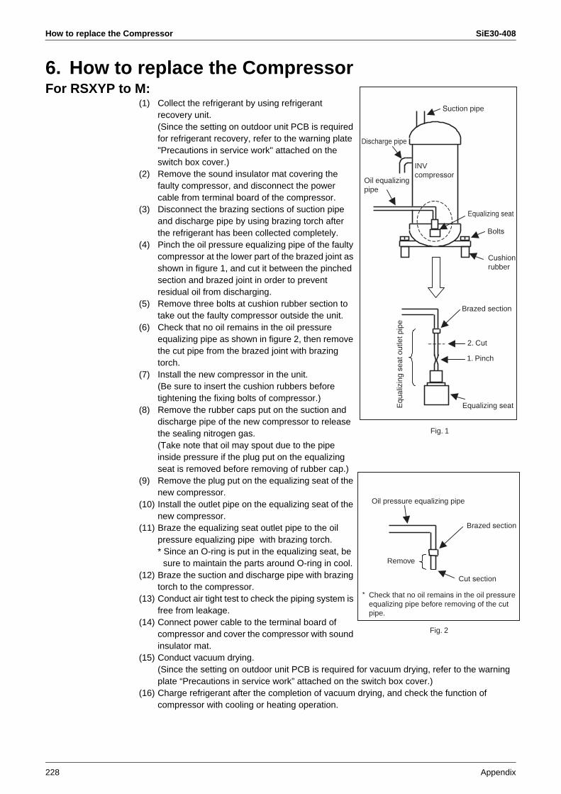
How to replace the Compressor SiE30-408
228 Appendix
6. How to replace the CompressorFor RSXYP to M:
(1) Collect the refrigerant by using refrigerant recovery unit.
(Since the setting on outdoor unit PCB is required for refrigerant recovery, refer to the warning plate "Precautions in service work" attached on the switch box cover.)
(2) Remove the sound insulator mat covering the faulty compressor, and disconnect the power cable from terminal board of the compressor.
(3) Disconnect the brazing sections of suction pipe and discharge pipe by using brazing torch after the refrigerant has been collected completely.
(4) Pinch the oil pressure equalizing pipe of the faulty compressor at the lower part of the brazed joint as shown in figure 1, and cut it between the pinched section and brazed joint in order to prevent residual oil from discharging.
(5) Remove three bolts at cushion rubber section to take out the faulty compressor outside the unit.
(6) Check that no oil remains in the oil pressure equalizing pipe as shown in figure 2, then remove the cut pipe from the brazed joint with brazing torch.
(7) Install the new compressor in the unit.(Be sure to insert the cushion rubbers before tightening the fixing bolts of compressor.)
(8) Remove the rubber caps put on the suction and discharge pipe of the new compressor to release the sealing nitrogen gas.(Take note that oil may spout due to the pipe inside pressure if the plug put on the equalizing seat is removed before removing of rubber cap.)
(9) Remove the plug put on the equalizing seat of the new compressor.
(10) Install the outlet pipe on the equalizing seat of the new compressor.
(11) Braze the equalizing seat outlet pipe to the oil pressure equalizing pipe with brazing torch.* Since an O-ring is put in the equalizing seat, be
sure to maintain the parts around O-ring in cool.(12) Braze the suction and discharge pipe with brazing
torch to the compressor. (13) Conduct air tight test to check the piping system is
free from leakage.(14) Connect power cable to the terminal board of
compressor and cover the compressor with sound insulator mat.
(15) Conduct vacuum drying.(Since the setting on outdoor unit PCB is required for vacuum drying, refer to the warning plate “Precautions in service work” attached on the switch box cover.)
(16) Charge refrigerant after the completion of vacuum drying, and check the function of compressor with cooling or heating operation.
Suction pipe
Discharge pipe
Equalizing seat
Bolts
Brazed section
2. Cut
1. Pinch
Equ
aliz
ing
seat
out
let p
ipe
Equalizing seat
Fig. 1
Oil pressure equalizing pipe
Brazed section
Cut section
Remove
Fig. 2
INVcompressor
Oil equalizingpipe
Cushionrubber
* Check that no oil remains in the oil pressureequalizing pipe before removing of the cutpipe.

SiE30-408 HRV-Related
Appendix 229
7. HRV-Related7.1 Group Interlock Control7.1.1 Single-group Interlocked Operation (Basic Pattern)
Purposes and Functions
The remote controller for indoor unit can control the interlocked operation with the HRV unit, and it can make an initial setting of the ventilation flow rate, the ventilation mode changeover and fresh-up operation. The HRV unit can independently be operated, even if the indoor unit is not in operation.
Note: 1. The remote controller should be connected to the terminal no. P1 and P2, the same as the group control wiring of indoor units.
2. Since this is two remote controller system (for Indoor unit and HRV unit), the Master / Slave setting is required.
Example of Control Wiring
Switch Setting for HRV Unit
No change is required. (as per factory setting)
Optional Accessories Required
None
Remote controller for SettingIndoor unit SlaveHRV unit Master
X9A
X10A
X11A
J1 J2 F1 F2
P1 P2
P1 P2
JC
SS1
F1 F2
P1 P2
P1 P2
Indoor unit HRV unit
Up to 500 m maximum(HC0025)
Remote controller for HRV unit
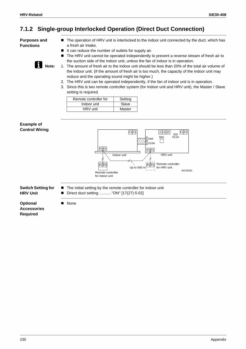
HRV-Related SiE30-408
230 Appendix
7.1.2 Single-group Interlocked Operation (Direct Duct Connection)
Purposes and Functions
The operation of HRV unit is interlocked to the indoor unit connected by the duct, which has a fresh air intake.It can reduce the number of outlets for supply air.The HRV unit cannot be operated independently to prevent a reverse stream of fresh air to the suction side of the indoor unit, unless the fan of indoor is in operation.
Note: 1. The amount of fresh air to the indoor unit should be less than 20% of the total air volume of the indoor unit. (If the amount of fresh air is too much, the capacity of the indoor unit may reduce and the operating sound might be higher.)
2. The HRV unit can be operated independently, if the fan of indoor unit is in operation.3. Since this is two remote controller system (for Indoor unit and HRV unit), the Master / Slave
setting is required.
Example of Control Wiring
Switch Setting for HRV Unit
The initial setting by the remote controller for indoor unitDirect duct setting ........... "ON" [17(27)·5·02]
Optional Accessories Required
None
Remote controller for SettingIndoor unit SlaveHRV unit Master
X9A
X10A
X11A
J1 J2 F1 F2
P1 P2
P1 P2
JC
SS1
F1 F2
P1 P2
P1 P2
Indoor unit HRV unit
Up to 500 m(HC0026)
Remote controller for indoor unit
Remote controller for HRV unit

SiE30-408 HRV-Related
Appendix 231
7.1.3 Operating the HRV Unit Using the Remote Controller of the VRV- system Air Conditioner
When the VRV-system air conditioner is connected with the HRV unit with a direct duct, the remote controller of the air conditioner cannot be used to select the VENTILATION mode. To use the HRV unit without operating the air conditioner, set the air conditioner in the FAN VENTILATION mode and select the low fan speed.1 Operation lamp2 Operation / stop button3 Operation mode display4 Operation mode selector
Every time the operation mode selector is pressed, the operation mode display changes as shown below.
Example
When the "FILTER" indication appears on the display, clean the filter of the HRV unit.
REMOTE CONTROL
TEST
TEST
H Lhr
hr
1 2
3
4
(HC0099)
Remote controller for VRV BRC1A51·52 / 61·62
/ Fan Ventilation
/ Cooling Ventilation
/ Fan Ventilation
/ Ventilation
/ Cooling Ventilation
(HC0100)
When air conditioner and HRV unit are not connected by duct
When air conditioner and HRV unit are connected by duct

HRV-Related SiE30-408
232 Appendix
7.1.4 Independent Operation of the HRV Unit Using the Centralized Controller (DCS302B61)
After selecting the zone where the only the HRV unit operation is desired, press the operation mode selector and select " " VENTILATION. The HRV unit can then be operated independently from the air conditioner.When the "FILTER" indication appears on the display, clean the filter of the HRV unit.
• • • • • • • •
CENTRAL REMOTE CONTROLLER
5
6
7
8
1
2
3
4
00 01 02 0303 04 05 06 07 0808 09 1010 11 12 1313 1414 15
C
HOST
ZONEZONE SELECTSELECT ZONEZONEGROUPGROUP No.No.
CODENo.No.
TESTTEST RESERESET
ALL ALL
OKZONEZONE
REFCIRCUIT
MONITORZONE
GROUPZONESET
REF.CIRCUIT
TEST
CODENo.No.
(HC0147)
OPERATION MODE selectorswitch
Operation mode display section (LCD)

SiE30-408 HRV-Related
Appendix 233
7.1.5 Interlocked Operation with 2 or More Group of VRV System
Purposes and Functions
When the HRV unit is interlocked to 2 or more group of indoor units, the HRV unit operates, if one of indoor unit in groups is in operation. The HRV unit can also be operated independently by remote controller for indoor unit, even if the indoor unit is not in operation.
Cautions: 1. It is not necessary to set the group number for central control. 2. One adapter PCB for remote control should be installed in the one of the unit connected to
the central transmission line. (When you install an adapter PCB for remote control in the indoor unit, select the applicable model number of Adapter PCB to be installed.)
Example of Control Wiring
Note: The central transmission line can be extended up to 1000 m maximum.
Switch Setting for HRV Unit
The initial setting by the remote controller for indoor unit or HRV unit.
Optional Accessories Required
Adapter PCB for remote control: KRP2A61
X9AX10A
X11A
J1 J2 F1 F2
P1 P2
JC
B1 B2 BC W1 W2 W3 W4
SS1
F1 F2
P1 P2
P1 P2
F1 F2
P1 P2
P1 P2
F1 F2
P1 P2
P1 P2
Up to 1000 m maximum
Indoor unit
Indoor unit
Indoor unit HRV unit
Remote controller for indoor unit
Remote controller for indoor unit
(HC0027)
KRP2A1(Installed in the HRV unit)
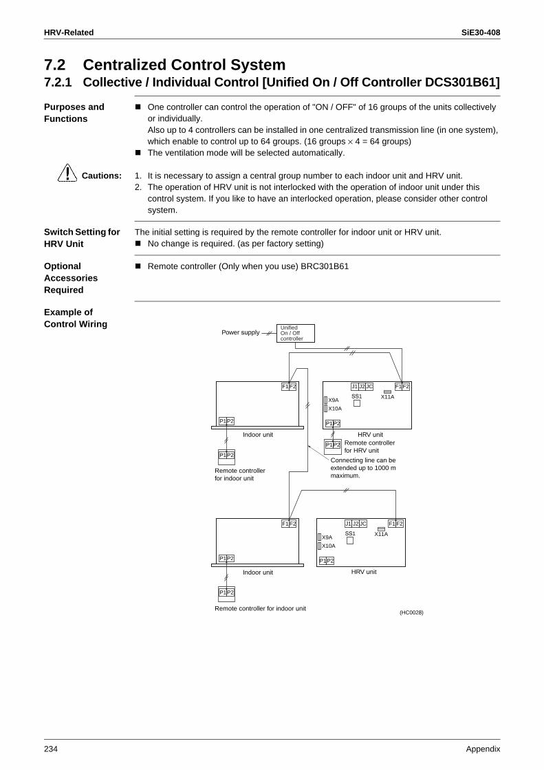
HRV-Related SiE30-408
234 Appendix
7.2 Centralized Control System7.2.1 Collective / Individual Control [Unified On / Off Controller DCS301B61]
Purposes and Functions
One controller can control the operation of "ON / OFF" of 16 groups of the units collectively or individually. Also up to 4 controllers can be installed in one centralized transmission line (in one system), which enable to control up to 64 groups. (16 groups × 4 = 64 groups) The ventilation mode will be selected automatically.
Cautions: 1. It is necessary to assign a central group number to each indoor unit and HRV unit. 2. The operation of HRV unit is not interlocked with the operation of indoor unit under this
control system. If you like to have an interlocked operation, please consider other control system.
Switch Setting for HRV Unit
The initial setting is required by the remote controller for indoor unit or HRV unit.No change is required. (as per factory setting)
Optional Accessories Required
Remote controller (Only when you use) BRC301B61
Example of Control Wiring
X9A
X10A
X11A
J1 J2 F1 F2
P1P2
JC
SS1
F1 F2
P1P2
P1P2
P1P2
X9A
X10A
X11A
J1 J2 F1 F2
P1P2
JC
SS1
F1 F2
P1P2
P1P2
Power supply
Indoor unit
Indoor unit
Remote controller for indoor unit
HRV unit
HRV unit
(HC0028)
UnifiedOn / Off controller
Remote controller for HRV unit
Connecting line can beextended up to 1000 m maximum.
Remote controller for indoor unit

SiE30-408 HRV-Related
Appendix 235
7.2.2 Zone Control System (Central Remote Controller DCS302B61)
Purposes and Functions
A maximum of 64 groups can be controlled On / Off individually by one controller. And also the central remote controller can control the On / Off operation of the units in each zone collectively. (It also can control the interlocked operation as well as the independent operation within the same zone.) If the zone setting is not required, or if you like to operate the HRV unit whenever one of indoor unit of any group connected to the central transmission line is in operation, refer to the applied system.
Cautions: 1. It is necessary to assign a central control group number. 2. If you operate the HRV unit interlocked to the operation of indoor unit, please set the same
zone number. At that time, it is necessary to set the zone operation on the HRV unit. 3. It is not possible to operate On / Off from the remote controller for the HRV unit in zone 1. 4. It is not necessary to set the zone operation mode in zone 2, which is already set at the
factory.
Switch Setting for HRV Unit
The initial setting is required by the remote controller for indoor unit or HRV unit.For zone 1 .........."ON" [17(27)·8·02]For zone 2 ..........Factory set (No change is required)
Optional Accessories Required
Remote controller (Only when you use) BRC301B61
Example of Control Wiring
X9A
X10A
X11A
J1 J2 F1 F2
P1P2
JC
SS1
F1 F2
P1P2
P1P2 P1P2
P1P2
X9A
X10A
X11A
J1 J2 F1 F2
P1P2
JC
SS1X9A
X10A
X11A
J1 J2 F1 F2
P1P2
JC
SS1
Zon
e 1
Zon
e 2
Power supply
Indoor unit
HRV unit
HRV unit
HRV unit
(HC0029)
Multi-functioncentrailized control
Remote controller for HRV unit
Remote controller for indoor unit
Remote controller for HRV unit

HRV-Related SiE30-408
236 Appendix
7.3 Examples of Mistakes in Wiring and System Designing7.3.1 It is Necessary to Install the Remote Controller for the Transmission
Line.
<Part 1> When you connect the transmission line for the remote controller, the remote controller should be installed on the transmission line.
Example of Control Wiring
Reason Because the signal through the transmission line is originated from the remote controller, there is no transmission signal to operate the units, if the remote controller is not installed.
7.3.2 The Centralized Transmission Line should be Connected to the Indoor Unit.
<Part 2> If the HRV unit is interlocked to the centralized controller, the central transmission line should be connected to the terminal no. F1 and F2 of indoor unit.
Example of Control Wiring
Reason The information from the indoor unit cannot be transmitted to the central controller through the HRV unit. And also the information from the central controller cannot be transmitted to the indoor unit through the HRV unit.
X9A X14A
X15A
X17AX10A
X11A
J1 J2 F1 F2
P1 P2
JC
SS1
F1 F2
P1 P2
(HC0041)
Indoor unit HRV unit
No remote controller
X9A
X10A
X11A
J1 J2 F1 F2
P1 P2
JC
SS1
F1 F2
P1 P2
P1 P2
(HC0042)
To central controller Centralized transmission line
Indoor unit HRV unit
Remote controller for indoor unit
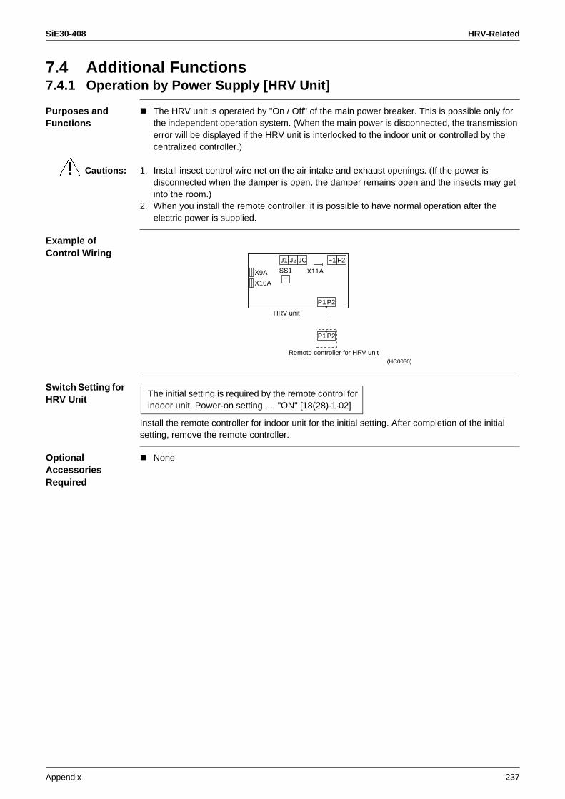
SiE30-408 HRV-Related
Appendix 237
7.4 Additional Functions7.4.1 Operation by Power Supply [HRV Unit]
Purposes and Functions
The HRV unit is operated by "On / Off" of the main power breaker. This is possible only for the independent operation system. (When the main power is disconnected, the transmission error will be displayed if the HRV unit is interlocked to the indoor unit or controlled by the centralized controller.)
Cautions: 1. Install insect control wire net on the air intake and exhaust openings. (If the power is disconnected when the damper is open, the damper remains open and the insects may get into the room.)
2. When you install the remote controller, it is possible to have normal operation after the electric power is supplied.
Example of Control Wiring
Switch Setting for HRV Unit
Install the remote controller for indoor unit for the initial setting. After completion of the initial setting, remove the remote controller.
Optional Accessories Required
None
X9A
X10A
X11A
J1 J2 F1 F2
P1 P2
P1 P2
JC
SS1
HRV unit
Remote controller for HRV unit(HC0030)
The initial setting is required by the remote control for indoor unit. Power-on setting..... "ON" [18(28)·1·02]

HRV-Related SiE30-408
238 Appendix
7.4.2 Monitor of Operation (KRP50-2) [HRV Unit → Operating Pilot Lamp (Local Supply)]
Purposes and Functions
To monitor the operation of one HRV unit.
Example of Control Wiring
Switch Setting for HRV Unit
No change is required. (as per factory setting)
Optional Accessories Required
Adapter PCB: KRP50-2
X9A
X10A
X11A
J1 J2 F1 F2
P1 P2
P1 P2
JC
SS1
123
L
power supply for pilot lampPilot lamp
[KRP50-2]
3P connector
2P connector
HRV unit
(HC0031)
Remote controller for HRV unit

SiE30-408 HRV-Related
Appendix 239
7.4.3 Fresh-up Operation by External Input [HRV Unit]
Purposes and Functions
When the operation is interlocked with the local ventilating fan (such as the one for toilet or kitchen), the HRV unit performs the over-supply operation to prevent the reverse flow of the odor. The flow rate of supply air becomes higher than that of exhaust air.
Example of Control Wiring
Local wiring
Notes: The connecting wiring between HRV unit and the terminal for local connection can be extended up to 50 m maximum.
Switch Setting of HRV Unit
No change is required. (factory setting)
Optional Accessories Required
None
Operation of HRV unit Terminal for local connection Capacity of connecting terminal
Fresh-up Short-circuit No-voltage normally open contact for micro-current 16 V, 10 mANormal Open circuit
X9A
X10A
X11A
J1 J2 F1 F2
P1 P2
P1 P2
JC
SS1
Connecting line can be extended up to 50 m maximum.
HRV unit
(Terminal for local connection)
Remote controller for HRV unit(HC0032)

HRV-Related SiE30-408
240 Appendix
7.4.4 Precool / Preheat Operation
Purposes and Functions
The operation of HRV unit is delayed when the air conditioner begins operation.
Cautions: 1. The precool / preheat function is possible only when the operation of HRV unit is interlocked to one-group or two-group of indoor unit.(It will not function when the HRV unit is in independent operation.)
2. You can select the preset time of 30 / 45 / 60 minutes for delayed operation at the time of initial setting.If this preset time is not sufficient, you can extend the preset time for further 30 / 60 / 90 minutes only the preheating function.
3. Since this is two remote controller system (for Indoor unit and HRV unit), the Master / Slave setting is required.
Example of Control Wiring
Switch Setting of the HRV Unit
The initial setting by the remote controller for the indoor unit. Precool / preheat On / Off setting. . . . . . . . . . . . . . . . . . . "ON" [17(27)·2·02]Precool / preheat time setting . . . . . . . . . . . . . . . . . . . . . "Time" [17(27)·3·*1]Preheat extra time setting . . . . . . . . . . . . . . . . . . . . . . . . "Time" [17(27)·9·*2]
*1 setting. . . . . . . . . . . . . 01 for 30, 02 for 45 and 03 for 60 minutes.*2 setting. . . . . . . . . . . . . 01 for 0 (factory set), 02 for 30, 03 for 60 and 04 for 90 minutes.
Optional Accessories Required
None
Remote controller for Setting
Indoor unit Slave
HRV unit Master
X9A
X10A
X11A
J1 J2 F1 F2
P1 P2
P1 P2
JC
SS1
F1 F2
P1 P2
P1 P2
Indoor unit HRV unit
(HC0033)
Remote controller for HRV unit
Connecting line can beextended up to 500 m maximum.
Remote controller for indoor unit
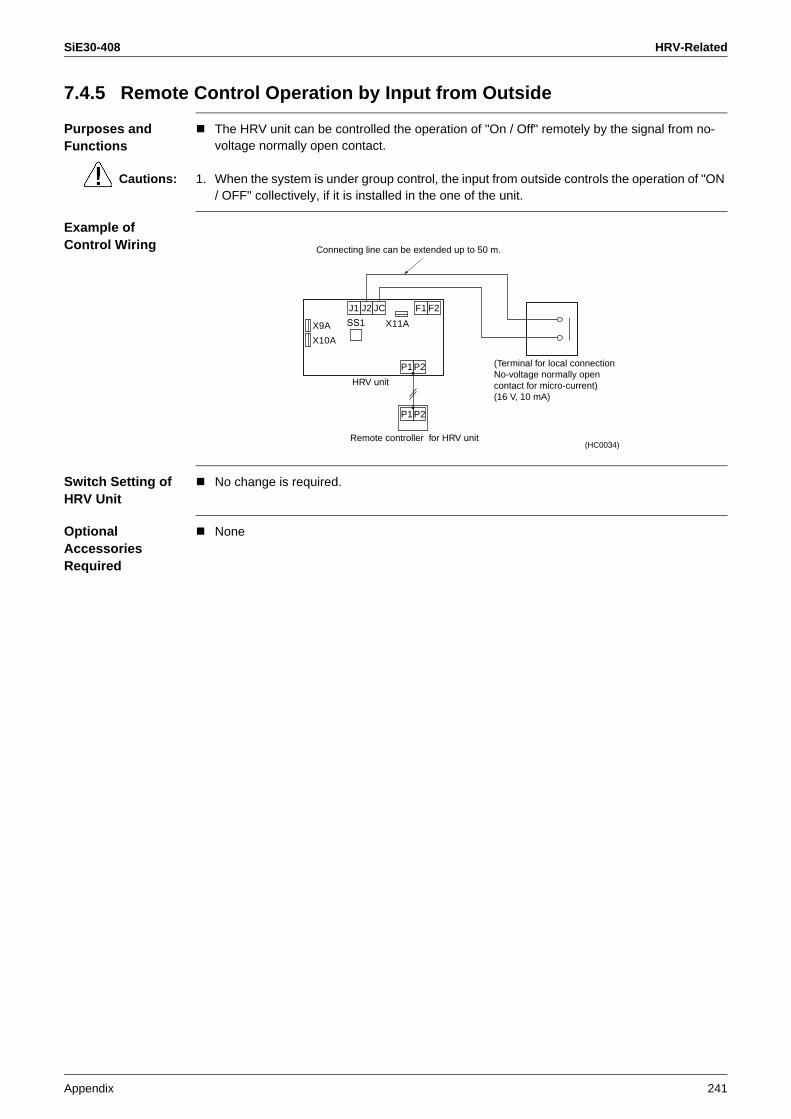
SiE30-408 HRV-Related
Appendix 241
7.4.5 Remote Control Operation by Input from Outside
Purposes and Functions
The HRV unit can be controlled the operation of "On / Off" remotely by the signal from no-voltage normally open contact.
Cautions: 1. When the system is under group control, the input from outside controls the operation of "ON / OFF" collectively, if it is installed in the one of the unit.
Example of Control Wiring
Switch Setting of HRV Unit
No change is required.
Optional Accessories Required
None
X9A
X10A
X11A
J1 J2 F1 F2
P1 P2
P1 P2
JC
SS1
Connecting line can be extended up to 50 m.
HRV unit
Remote controller for HRV unit(HC0034)
(Terminal for local connection No-voltage normally open contact for micro-current)(16 V, 10 mA)

HRV-Related SiE30-408
242 Appendix
7.5 Central Control System (DCS302B61) 7.5.1 Collective / Individual Operation (Central Remote Controller)
Purposes and Functions
It is possible to have collective On / Off or individual On / Off without zone control (while setting the 64 zones).It is also possible to connect the unified On / Off controller and etc.
Cautions: 1. It is required the local setting of the group number for central control. 2. The HRV unit judges the ventilation mode individually.
Example of Control Wiring
Switch Setting of the HRV Unit
The initial setting is required by the remote controller for indoor unit. Collective zone interlock setting. . . . . . . . . . . . . . . . . . . . "OFF" (as per factory set)
Optional Accessories Required
Central remote controller DCS302B61
X9A
X10A
X11AJ1 J2 F1 F2
P1 P2
P1 P2
JC
SS1
F1 F2
P1 P2
P1 P2
X9A
X10A
X11AJ1 J2 F1 F2
P1 P2
P1 P2
JC
SS1
F1 F2
P1 P2
P1 P2
T1 T2D1D2
F1 F2TeS1
Central remote controller
Power supply
Indoor unit HRV unit
Indoor unit HRV unit
(HC0036)
Connecting line can be extended up to 1000 m maximum.
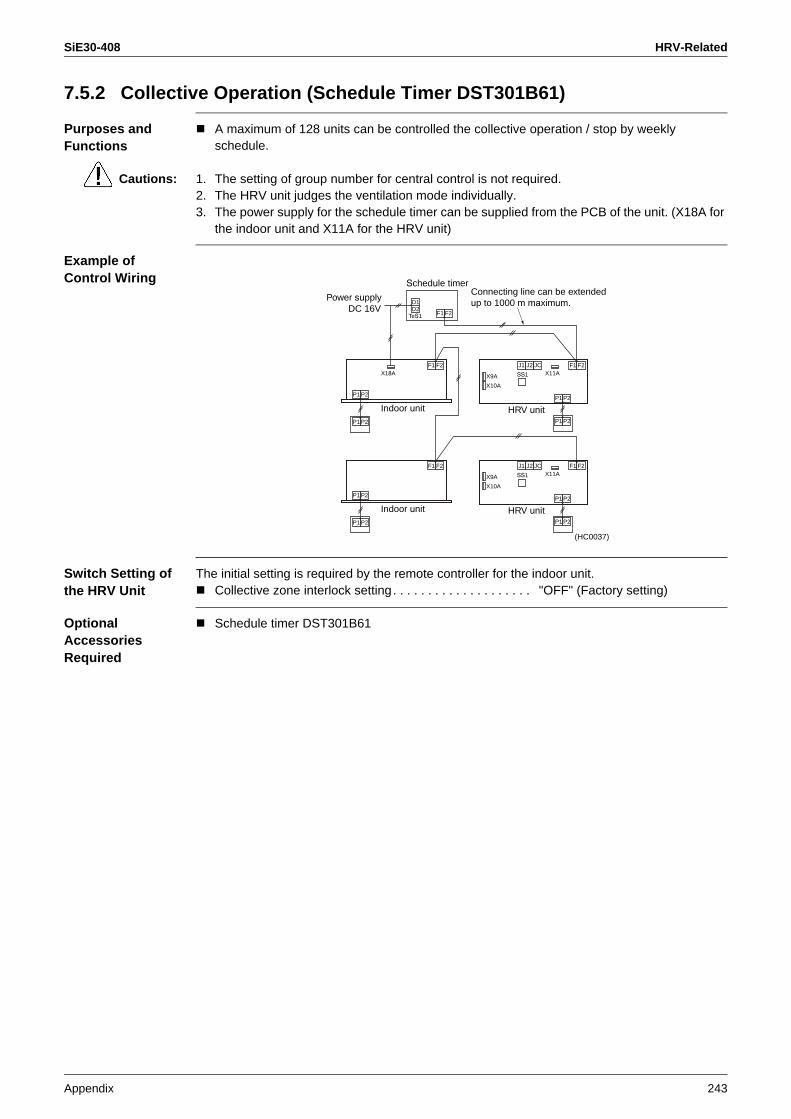
SiE30-408 HRV-Related
Appendix 243
7.5.2 Collective Operation (Schedule Timer DST301B61)
Purposes and Functions
A maximum of 128 units can be controlled the collective operation / stop by weekly schedule.
Cautions: 1. The setting of group number for central control is not required. 2. The HRV unit judges the ventilation mode individually. 3. The power supply for the schedule timer can be supplied from the PCB of the unit. (X18A for
the indoor unit and X11A for the HRV unit)
Example of Control Wiring
Switch Setting of the HRV Unit
The initial setting is required by the remote controller for the indoor unit.Collective zone interlock setting. . . . . . . . . . . . . . . . . . . . "OFF" (Factory setting)
Optional Accessories Required
Schedule timer DST301B61
X9A
X10A
X11AJ1 J2
X18AF1 F2
P1 P2
P1 P2
JC
SS1
F1 F2
P1 P2
P1 P2
X9A
X10A
X11AJ1 J2 F1 F2
P1 P2
P1 P2
JC
SS1
F1 F2
P1 P2
P1 P2
D1D2
F1 F2TeS1
Schedule timer
Indoor unit HRV unit
Indoor unit HRV unit
(HC0037)
Power supplyDC 16V
Connecting line can be extended up to 1000 m maximum.

HRV-Related SiE30-408
244 Appendix
7.5.3 Collective Operation [Adapter PCB for Remote Control KRP2A Series]
Purposes and Functions
A maximum of 64 groups can be controlled the operation of "ON / OFF" collectively. (For the individual control, use the central remote controller or the unified On / Off controller.)
Cautions: 1. Adapter PCB can be installed in any unit connected to the central transmission line. 2. It cannot be used with other central controller. 3. The setting of group number is not required. 4. The HRV unit judges the ventilation mode individually.
Example Control Wiring
Switch Setting of the HRV Unit
The initial setting is required by the remote controller for the indoor unit or HRV unit.Collective zone interlock setting. . . . . . . . . . . . . . . . . . . . "OFF" (as per factory setting) The setting of switch on the PCB Voltage / no-voltage changeover switch(SS1) . . . . . . . . . "no-voltage"
* Remote control mode changeover switch (RS1) should be selected.
Optional Accessories Required
Adapter PCB for remote control KRP2A61
B1 B2 BC W1 W2 W3 W4
X9A
X10A
X11AJ1 J2
X18A
F1 F2
P1 P2
P1 P2
JC
SS1
F1 F2
P1 P2
P1 P2
X9A
X10A
X11AJ1 J2 F1 F2
P1 P2
JC
SS1
F1 F2
P1 P2
P1 P2
Indoor unit HRV unit
Indoor unit HRV unit
(HC0038)
Connecting line can beextended up to 150 m maximum.
Remote control board(local supply)
ON / OFF No-voltage normallyopen contact for micro-current
Remote controller for HRV unit
PCB board KRP2A series(installed in the indoor unit)
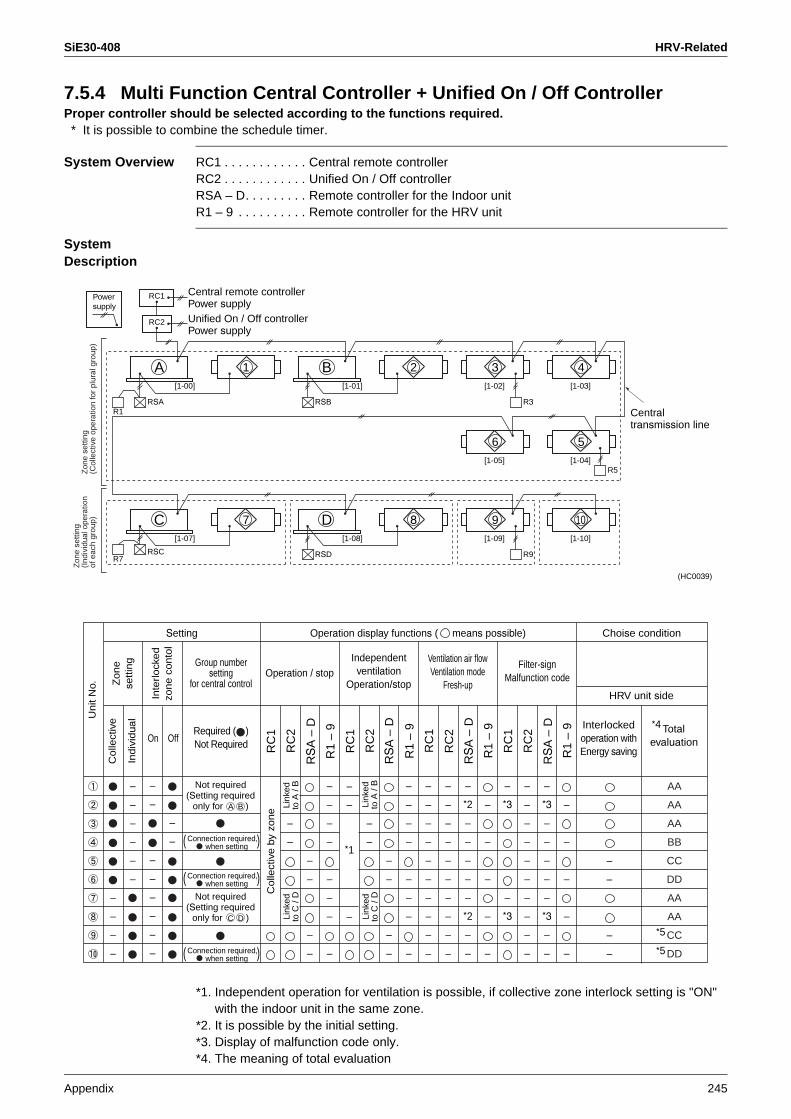
SiE30-408 HRV-Related
Appendix 245
7.5.4 Multi Function Central Controller + Unified On / Off ControllerProper controller should be selected according to the functions required. * It is possible to combine the schedule timer.
System Overview RC1 . . . . . . . . . . . . Central remote controllerRC2 . . . . . . . . . . . . Unified On / Off controllerRSA – D. . . . . . . . . Remote controller for the Indoor unitR1 – 9 . . . . . . . . . . Remote controller for the HRV unit
SystemDescription
*1. Independent operation for ventilation is possible, if collective zone interlock setting is "ON" with the indoor unit in the same zone.
*2. It is possible by the initial setting.*3. Display of malfunction code only.*4. The meaning of total evaluation
RSA
[1-00]
R1
A 1
RSB
[1-01]
B 2
RSC
[1-07]
R7
C 7
RSD
[1-08]
D 8
R3
[1-03]
4[1-02]
3
[1-04]
5[1-05]
6
R5
R9
[1-10]
10[1-09]
9
RC2
RC1
(HC0039)
Zon
ese
tting
(Ind
ivid
ual o
pera
tion
of e
ach
grou
p)Z
one
setti
ng(C
olle
ctiv
e op
erat
ion
for
plur
al g
roup
)
Power supply
Central remote controller Power supplyUnified On / Off controller Power supply
Centraltransmission line
–
–
–
–
Totalevaluation
–
–
–
–
–
–
–
–
–
–
–
–
–
–
–
–
–
–
–
–
–
–
–
–
–
–
–
–
–
–
–
–
–
–
–
–
–
–
–
–
–
–
–
–
–
–
–
–
–
–
–
–
*1
–
–
–
–
–
–
–
–
–
–
–
–
–
–
–
–
–
–
–
–
–
–
*2
–
–
–
–
–
*2
–
–
–
–
–
–
–
–
*3
–
*3
–
–
–
–
–
–
–
–
–
–
–
*3
–
–
–
–
–
*3
–
–
–
–
–
–
–
On Off
Setting Operation display functions ( means possible) Choise condition
HRV unit side
Interlockedoperation withEnergy saving
Required ( )Not Required
Not required(Setting required
only for A B )
Not required(Setting required
only for C D )
Connection required, when setting
Connection required, when setting
Connection required, when setting
Operation / stopIndependentventilation
Operation/stop
Ventilation air flowVentilation mode
Fresh-up
Group numbersetting
for central control
Filter-signMalfunction code
*4
*5
*5
AA
AA
AA
BB
CC
DD
AA
AA
CC
DD
( )
( )
( )
Co
llect
ive
by
zon
e
Un
it N
o. Zo
ne
sett
ing
Inte
rlo
cke
d
zon
e c
on
tol
Ind
ivid
ual
Co
llect
ive
RC
1
RC
2
RS
A –
D
R1
– 9
RS
A –
D
R1
– 9
RC
1
RC
2
RS
A –
D
R1
– 9
RC
1
RC
2
RS
A –
D
R1
– 9
RC
1
RC
2
Link
edto
A /
BLi
nked
to C
/ D
Link
edto
A /
BLi
nked
to C
/ D

HRV-Related SiE30-408
246 Appendix
AA: Interlocked operation with energy saving and changeable of Ventilation mode / Air flow rate
BB: Interlocked operation with energy saving and no changeable of Ventilation mode / Air flow rate
CC: No interlocked operation with energy saving and changeable of Ventilation mode / Air flow rate
DD: No interlocked operation with energy saving and no changeable of Ventilation mode / Air flow rate
*5. Interlocked operation setting must not be done for individual zone. (Because there is no unit to combine in zone except 1 unit.)

SiE30-408
Index i
Abnormal Discharge Pipe Temperature in Cooling Operation ........................................................99
Actuation of Freeze-up Prevention Control of Indoor Unit ..................................................................97
Actuation of HPS in Heating Operation ..................98AirNet address of indoor unit ..................................48
Bending Radius in Pipe and Flare Tightening Torque ...........................................19
Calculate Cooling / Heating Capacity ...................198Calculation List on Equivalent Length of Joint .......19Central Control System ........................................242Characteristics of Refrigerant
R22 ................................................................192R407C ...........................................................193R410A ............................................................195
Checker Connection .............................................181collect or analyze data on the Service Checker ...131Collection and Playback of Data on Checker .......146Component Function ..............................................37Components of indoor unit ...............................37, 40Components of outdoor unit .......................37, 39, 40Compressor Capacity Control ................................26Conduct Analysis .................................................178Control of Electronic Expansion Valve ...................27
Defective Lubrication of Compressor ...................101DIII-NET Expander Adaptor .................................221Drain Pump Control ................................................30
Effective Use of Checker ......................................180Electronic Expansion Valve ....................................83Evacuation Mode ...................................................65Excessive / Insufficient Charging of Refrigerant ....72External Control Adaptor of Outdoor Unit ............216
Field Setting on Outdoor UnitMonitor Mode ...................................................61Setting Mode 1 ................................................57Setting Mode 2 ................................................58
Field Settings for the Replacement of the Spare Control PC Board ..........................................199
Field Settings from Remote ControllerGroup No. for Centralized Control System ......45Individual Functions for Indoor Unit .................43
Forcedly fan ON .....................................................52Four-way Valve ......................................................85Freeze-up Prevention Control ................................31
Functional Parts .................................................... 39
Guideline for Tightening Flare Nut ........................ 19
Heater Control of VRV System ............................. 32
Individual setting ................................................... 52Indoor unit sensor ........................................... 37, 39
Length of Refrigerant Piping ................................. 17
Method of Use by SymptomIn the Case of Faulty Compressor ................ 178In the Case of Malfunction of Cooling ........... 178In the Case of Malfunction of Heating ........... 178
Monitor on Inverter PC Board ............................... 92
Outdoor Fan Motor ................................................ 89Outdoor unit sensor ......................................... 37, 39
P-H Diagram ......................................................... 22Processing Dimension for Flare Section ............... 19Psychrometric Chart ............................................ 197
R410A Thermodynamical Characteristics ........... 196Recording and Playback of Operation Data ........ 137Refrigerant Control of VRV System ....................... 24Refrigerant Piping ................................................. 19Refrigerant Recovery Mode .................................. 65Refrigeration Cycle ................................................ 23Remote Control Mode Selector Switch (RS1) ..... 206
Solenoid Valve ...................................................... 87Super Wiring System ............................................ 15
Target Pressure and Temperature ........................ 72Thermistor Temperature ·
Resistance Characteristic .............................. 79Thermostat-control ................................................ 28Two-way Solenoid Valve ....................................... 88
Unit No. transfer .................................................... 52

SiE30-408
ii Index
Versatile Usage ....................................................225Voltage Characteristic of Pressure Sensor
R22, R407C .....................................................81R410A ..............................................................82
Voltage Measuring Point ........................................80VRV system multi indoor unit settings ....................44
Water Leakage from Indoor Unit ..........................100Wiring Adaptor for Electrical Appendices .....201, 209

SiE30-408
Drawings & Flow Charts iii
Abnormal discharge pipe temperature Liquid injection does not turn ON. .................184
Address Settings ....................................................47AirNet Address .......................................................48
Centralized Controller (DCS302B61) ...................232Centralized Controllers .........................................208Changed to the VTCF two-core line .....................124Characteristics of Refrigerant
R22 ................................................................192R407C ...........................................................193R410A ............................................................195
Check on Outdoor Fan Motorconnector of fan motor .....................................89connector of fan motor (control cable) .............89pulse input of fan inverter PC board position
signal ..................................................89Check on Service Data ..........................................49Checker Connection .............................................181Collective / Individual Control [Unified On / Off
Controller DCS301B61] ................................234Collective / Individual Operation (Central Remote
Controller) .....................................................242Collective Operation
(Schedule Timer DST301B61) ......................243Collective Operation [Adapter PCB for Remote
Control KRP2A Series] .................................244Completes by attaching an accessory wire ..........111Compressor Capacity Control ................................26Connection to Indoor Unit
group unified display ......................................210Individual control ............................................210individual display ...........................................211zone unified control .......................................211
Connection to indoor unit .....................................202Construction of Thermistor .....................................78CONTROL MODE selector switch (RS1) .............203Conventional system ............................................222Cooling / Heating Selection System
Type A .............................................................11Type B .............................................................12Type C .............................................................13
Cooling/Heating Differential ...................................33
Default condition of DIP switchRSXYP5, 8, 10L ............................................200RXY5 ~ 48M, RX5 ~ 48M, RXYQ5 ~ 48M,
REYQ8 ~ 48M ..................................199display signals ......................................................205distant control (operation) ....................................202Diversification of risk of centralized control system
Conventional system .....................................225
extended adapter .......................................... 225Drain Pump Control ............................................... 30
Electric and Functional ComponentsRSXY8, 10K and RSXYP8, 10KJ ................... 36RXY(Q)14, 16M .............................................. 38
Electronic Expansion ValveEBM type linear control valve ......................... 83Gas Leakage .................................................. 84Malfunction (Complete Close) ........................ 84Malfunction (Full Open) .................................. 84
Example of Wiring ............................................... 224Excessively Charged Refrigerant Gas .................. 73expander adapter ................................................ 222
Field Settingsdemand and low noise operation .................. 219function switch SS1 ...................................... 220independent "COOL/HEAT address" and
"demand address ............................. 220the operation mode (cool, heat, fan) ............. 219
Field Settings from Remote Controller .................. 42Group No. for Centralized Control System ..... 45Individual Functions for Indoor Unit ................ 43
Flared shape ......................................................... 19Four-way Valve
for heat pump type air conditioner .................. 85Movement in Cooling ...................................... 85Operation in Heating ....................................... 86
Freeze-up Prevention Control ............................... 31Fresh-up Operation by External Input
[HRV Unit] .................................................... 239
Heat Recovery System ......................................... 14
Install a trap to the drain on the equipment side .................................. 122
Insufficient Refrigerant Gas ................................... 74Interlocked Operation with 2 or More Group of
VRV System ................................................. 233
L joint ..................................................................... 19Length of Refrigerant Piping
RSXY(P) ~ KA(L) ............................................ 17RX(Y)(Q) ~ M .................................................. 18
Malfunction in Cooling Operation .......................... 70Malfunction in Heating Operation .......................... 71

SiE30-408
iv Drawings & Flow Charts
Method of extending systemcutting jumper wires .......................................227Example of basic wiring .................................227
Method to Specify the Indoor Unit No. ...................53Mistakes in Wiring and System Designing
Part 1 .............................................................236Part 2 .............................................................236
Monitor of Operation (KRP50-2) ..........................238Mounting Sensor Kit .............................................182Multi Function Central Controller + Unified On / Off
Controller ......................................................245
Operation by Power Supply [HRV Unit] ...............237operation mode display ........................................231Operation Range of Remote Controller
Thermostat ......................................................28Overview of System
Batch selection of operation mode ................216Demand control / Low noise control ..............216
Overview of system ..............................................209
P-H Diagram ..........................................................22Points of Super Wiring System ..............................15Precool / Preheat Operation .................................240Principal of Valve Operation ...................................88Psychrometric Chart .............................................197
Recovers by correcting the wire connections .......112REFNET header .....................................................19REFNET joint .........................................................19Refrigerant Control of VRV System
Cooling Operation ............................................24Heating Operation ...........................................25
Refrigeration Cycle .................................................23Relaxation of restrictions on branching DIII-NET
Conventional system .....................................226expander adapter ..........................................226
Remote Control Operation by Input from Outside ..........................................................241
Remote Controller of the VRV- system Air Conditioner ..............................................231
replace the Compressor .......................................228
Save Data ............................................................183Service Settings .....................................................51Settings of Group No. .............................................46Single-group Interlocked Operation
(Basic Pattern) ..............................................229Single-group Interlocked Operation
(Direct Duct Connection) ...............................230Solenoid Valve .......................................................87
Target Evaporation Temperature ...........................26temperature settings ............................................204the connection wiring to the terminal block ..........223The limits for wiring ..............................................222
The number of units for centralized control ......... 221the temperature difference .................................. 116Thermistor Malfunction .......................................... 78time chart of remote controller commands and
indoor unit against input signals ................... 207Transmission System Malfunction
An example of illustration ................................ 93Trap bend .............................................................. 19
Understanding of Malfunction Code ...................... 90Using long pipes .................................................. 114
Ve-up STD RSXYP 5-10LMalfunction of heating ................................... 189
Voltage Characteristic of Pressure SensorR22, R407C .................................................... 81R410A ............................................................. 82
Voltage Measuring Point ....................................... 80VRV II Heat recovery type: Malfunction of heating
Data on occurrence of malfunction while in all-unit heating operation ................. 186
Graph of indoor unit (1) ................................. 186Graph of indoor unit (2) ................................. 187Graph of indoor unit (3) ................................. 187Graph of indoor unit (4) ................................. 188Graph of indoor unit (5) ................................. 188
WaveformFaulty waveform ............................................. 95Noise ............................................................... 95Ringing ............................................................ 95Round pulse .................................................... 95waveform at start-up ....................................... 95
Wiring .................................................................. 217Wiring Length ........................................................ 16Wiring to External Controller
CONTROL MODE selector switch (RS1) ..... 212display signals .............................................. 214distant control (operation) ............................. 212temperature settings ..................................... 214
Zone Control System (Central Remote Controller DCS302B61) ................................................ 235
VRV products are not within the scope of the Eurovent certification programme.
ISO14001 assures an effective environmental management system in order to help protect human health and the environment from the potential impact of our activities, products and services and to assist in maintaining and improving the quality of the environment.
Daikin Europe N.V. is approved by LRQA for its Quality Management System in accordance with the ISO9001 standard. ISO9001 pertains to quality assurance regarding design, development, manufacturing as well as to services related to the product.
Daikin units comply with the European regulations that guarantee the safety of the product.
Zandvoordestraat 300
B-8400 Ostend - Belgium
www.daikineurope.com SiE3
0-40
8 •
02/2
005
Prep
ared
in B
elgi
um b
y La
nnoo
Specifications are subject to change without prior notice