distributed*lighting*control* - técnico lisboa - autenticação · •...
TRANSCRIPT

Distributed Real-‐Time Control Systems Project, 2013-‐2014 Page 1
Master Degree in Electrical and Computer Engineering 2013/2014 – Winter Semester
Distributed Real-Time Control Systems
(Sistemas de Controlo Distribuído em Tempo-Real)
PROJECT
Distributed Lighting Control
Prepared by
Alexandre Bernardino
João Paulo Neto
P Instituto Superior Técnico
Department of Electrical and Computer Engineering
Scientific Area of Systems, Decision and Control
Distributed Real-‐Time Control Systems Project, 2013-‐2014 Page 2
Instructions for the project
The students must form groups of three to execute the project. There are weekly laboratory sessions of 1.5hr each where the students will access the relevant equipment to progress in the execution of the project and receive guidance from the teaching staff. Some equipment is available for students to take home in order to experiment and advance on points not requiring lab access.
The students have to perform two demonstrations of the project: one in the middle of the semester (28th October) showing the progress done up to that point and other in the end of the semester to show the full project (16th December). Then the group has to write a report to be delivered a couple of weeks after the last demonstration (30th December).
The report must be direct, concise and short but insightful. Together with the report, the software developed to execute the project should be delivered.
Both the report and the software must be sent to the professor in charge of the laboratory within the prescribed time limits.
The reports and the software developed must be original. All forms of plagiarism or copy detected will be punished without contempt according to IST regulations and the Portuguese Law.

Distributed Real-‐Time Control Systems Project, 2013-‐2014 Page 3
Read this with attention!
Safety warnings
• To avoid being injured, the students should not touch or look directly to the high-‐power led lights used in the project.
• Other groups and courses share the lab equipment. Students should only use the equipment required for their particular project, and use it with care to avoid damaging or de-‐calibrating the setups.
• In case of malfunction or fire, the students should immediately shut down the power switch on their desk and call the teaching staff.
• In case of gross misuse of the equipment or violation of its operational limits, the students will be liable for the replacement of the damaged equipment.
Leia isto com atenção!
Avisos de segurança
• Para evitar ferimentos e queimaduras, os alunos não devem tocar ou olhar diretamente para os led’s de iluminação usados no projeto.
• O equipamento do laboratório é partilhado por outros grupos de alunos e por outras disciplinas. Os estudantes devem utilizar apenas o equipamento necessário para o seu projeto, e usá-‐lo com cuidado para não danificar ou descalibrar.
• Em caso de avaria ou incêndio, os estudantes deverão desligar imediatamente o disjuntor da bancada e chamar o professor presente no laboratório.
• Em caso de má utilização grosseira do equipamento ou violação dos seus limites de funcionamento, os estudantes poderão ser responsabilizados pela substituição de qualquer equipamento danificado.
Notice also:
• You must always bring to the lab the equipment taken home since this is required for the lab sessions.
• You must always bring to the lab a flash drive to store the results obtained during the class;
• When using the lab computers make sure that you are using a working folder with write permissions (can be an external flash drive).

Distributed Real-‐Time Control Systems Project, 2013-‐2014 Page 4
Take home material
• 1 Arduino UNO Rev. 3
• 1 USB cable
• 1 Breadboard
• 1 Set of multiclored jumper wires.
• 1 Sharp Distance Sensor GP2Y0A21 and jumper wire.
• 1 Servo Motor HITEC H-‐S322HD
• 8 Single color LED’s.
• 1 RGB LED
• 8 330 Ohm resistors
• 1 1 MOhm resistor
• 1 10 KOhm resistor
• 2 10 KOhm Potentiometers
• 2 Push buttons
• 1 Piezo buzzer
• 1 Piezo knock sensor
• 1 Photo resistor
Distributed Real-‐Time Control Systems Project, 2013-‐2014 Page 5
Homeworks
To learn the arduino programming language, real-‐time primitives, communications and I/O to interface with sensors and actuators, students should do the homeworks described in the eBook available at www.introtoarduino.com. The take-‐home material allows the execution of the following exercises: Chapter 1, Chapter 2, Chapter 3 (3.3 w/ 2 instead of 3 potentiometers), Chapter 4 (w/ piezo buzzer instead of speaker), 7.2, 7.5, 7.6 (exercises 1 and 4), 8.1. Additionally, the students can prepare and test at home the code to read the distance sensor. The thermometer circuit, high-‐power LED and fan drive circuits are only available in the lab.
Distributed Real-‐Time Control Systems Project, 2013-‐2014 Page 6
1. Introduction
With the increasing prices on electricity, large research efforts have been put in the search for efficient illumination systems during the last decade. Advances in semiconductors has brought us high power LED’s that allow up to 85% saving in energy consumption and high versatility of use due to their small size and dimming ability. Additionally, improvements in technology and reductions in price are making LED the favourite illumination devices for home, automotive, office and smart building spaces (www.ledmarketresearch.com).
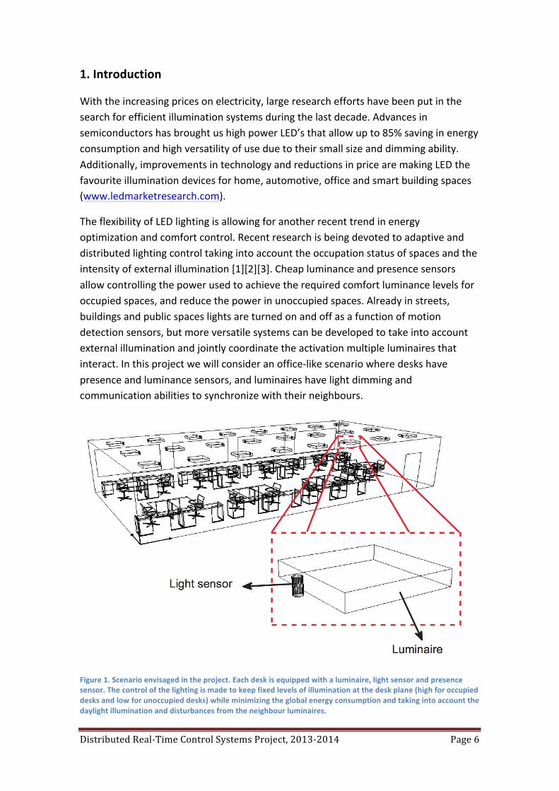
The flexibility of LED lighting is allowing for another recent trend in energy optimization and comfort control. Recent research is being devoted to adaptive and distributed lighting control taking into account the occupation status of spaces and the intensity of external illumination [1][2][3]. Cheap luminance and presence sensors allow controlling the power used to achieve the required comfort luminance levels for occupied spaces, and reduce the power in unoccupied spaces. Already in streets, buildings and public spaces lights are turned on and off as a function of motion detection sensors, but more versatile systems can be developed to take into account external illumination and jointly coordinate the activation multiple luminaires that interact. In this project we will consider an office-‐like scenario where desks have presence and luminance sensors, and luminaires have light dimming and communication abilities to synchronize with their neighbours.
Figure 1. Scenario envisaged in the project. Each desk is equipped with a luminaire, light sensor and presence sensor. The control of the lighting is made to keep fixed levels of illumination at the desk plane (high for occupied desks and low for unoccupied desks) while minimizing the global energy consumption and taking into account the daylight illumination and disturbances from the neighbour luminaires.

Distributed Real-‐Time Control Systems Project, 2013-‐2014 Page 7
2. Objective
The objective of this project consists on the real-‐time control of a distributed illumination system installed in the lab. Each desk has an illumination system (luminaire) composed by a presence sensor to detect if the desk is occupied or empty, a high-‐power dimmable led to illuminate the desk, and a photo-‐resistor to measure the luminance level. The objective is to minimize the energy consumption by controlling the dimming level of each high-‐power led such that occupied desks have luminance levels above a high threshold and unoccupied desks have a low luminance level above a low threshold. The system should take into account daylight illumination and interference from neighbour luminaires, so local control alone will not suffice to solve the problem in an optimal way. Communications between neighbour luminaires will be considered to tackle the problem. The students will design controllers with different communication methods and compare their performance: local control, centralized control and distributed control. In local control no explicit communication is allowed between different luminaires and only cares about its own desk. In centralized control, a controller has access to the information of all luminaires (luminance and dimming levels) and computes a global optimal control law. In decentralized control, each luminaire can communicate with its neighbours and exchange information until together agree on an optimal control law.
2.Plant Description
The distributed illumination system is installed in the lab LSDC2 at the IST North Tower, floor 5. There are 8 working desks and each desk has available the following equipment:
• A dimmable high-‐power led and corresponding transistor driver assembled in an aluminium heat sink. The led operates with voltages between 9V and 12V, and in this project should be set to 10V. Dimming will be implemented via PWM at the base of the transistor driver.
Figure 2 – A 10W Power LED, 9V-‐12V, 900 Lumens.
Distributed Real-‐Time Control Systems Project, 2013-‐2014 Page 8
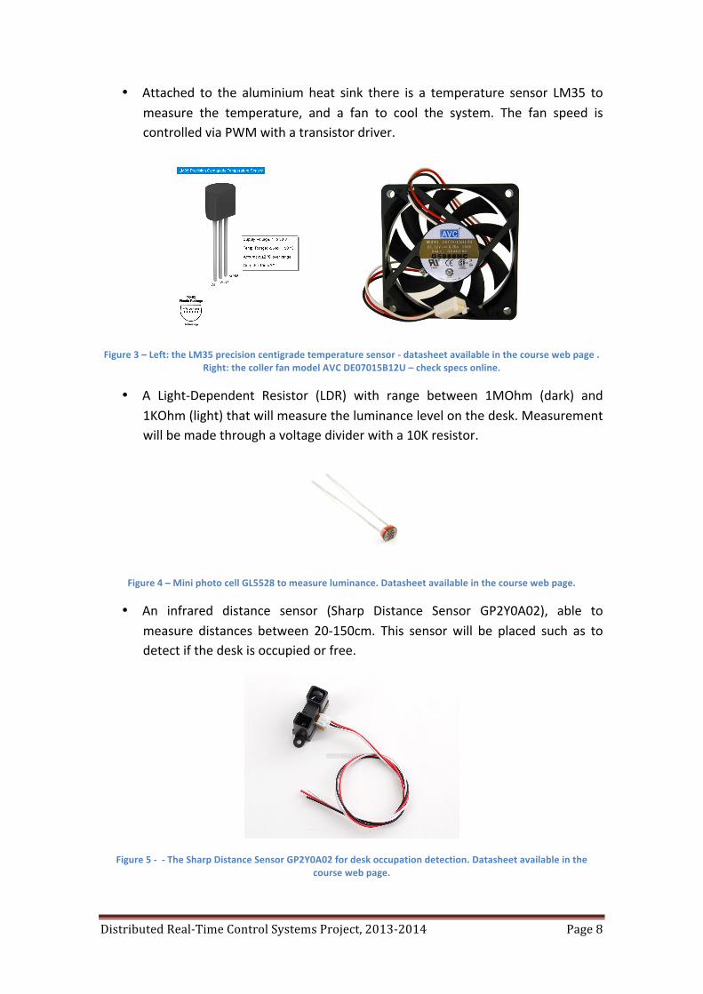
• Attached to the aluminium heat sink there is a temperature sensor LM35 to measure the temperature, and a fan to cool the system. The fan speed is controlled via PWM with a transistor driver.
Figure 3 – Left: the LM35 precision centigrade temperature sensor -‐ datasheet available in the course web page . Right: the coller fan model AVC DE07015B12U – check specs online.
• A Light-‐Dependent Resistor (LDR) with range between 1MOhm (dark) and 1KOhm (light) that will measure the luminance level on the desk. Measurement will be made through a voltage divider with a 10K resistor.
Figure 4 – Mini photo cell GL5528 to measure luminance. Datasheet available in the course web page.
• An infrared distance sensor (Sharp Distance Sensor GP2Y0A02), able to measure distances between 20-‐150cm. This sensor will be placed such as to detect if the desk is occupied or free.
Figure 5 -‐ -‐ The Sharp Distance Sensor GP2Y0A02 for desk occupation detection. Datasheet available in the course web page.

Distributed Real-‐Time Control Systems Project, 2013-‐2014 Page 9
• A computer running Linux and connected to the computers in the other desks through an Ethernet local area network (LAN).
• A regulated power supply that will provide enough current to drive the high-‐power led. This power supply should be always configured to an output voltage of 10V. The students are responsible for checking this before connecting any equipment.
• An arduino board (UNO Rev. 3) that will implement the local controller: drive the led power via digital PWM output, measure the LDR and infrared distance sensor outputs in analog input pins, and will communicate to the computer via serial communications through the USB link.
3.Work Stages
The project is divided in two major parts.
In the first part students will implement the local controller using the arduino board and basic serial communications to the computer. This part will be evaluated through a demonstration of the local illumination control in the middle of the semester (28th October).
In the second part the students will implement the global centralized and distributed controllers using C++ programs running in the computers to implement the control algorithms, socket based communications to the other computers and serial communications to the arduino. This part will be evaluated through a demonstration of the final distributed control system in the end of the semester (16th December).
A written report containing both parts, and associated software, will be delivered two weeks after the final demonstration (30th December).
Distributed Real-‐Time Control Systems Project, 2013-‐2014 Page 10
4. Implementation
Part 1.
In this part the students will implement the local illumination controller using both the equipment taken home and the equipment available in the lab. Use the supplied material to assemble, in the breadboard, the required circuits to implement the local controller.
The students will have 4 sessions of 1.5h (30th September, 7th, 14th and 21st October) to implement the following functions:
1 -‐ Measuring luminance with an LDR. (Hint: Use a voltage divisor with a 10KOhm resistor). Actuate a signalling LED whenever the LDR resistance is below 100KOhm (too dark) and another one when the LDR resistance is below 10KOhm (bright enough). These values will set the minimum luminance levels for the non-‐occupied and occupied desk conditions.
2 -‐ Measuring proximity with the Sharp Distance Sensor. Turn on a signalling LED whenever the desk is occupied. Define the condition occupied if the proximity sensor measures a distance below 50cm.
3 -‐ Measuring temperature. Turn on a signalling LED whenever the temperature of the luminaire is above 50 degrees centigrade.
4 -‐ Driving the LED luminaire. Control the dimming level of the high power LED luminance to a value proportional to the position of a potentiometer, between its minimum and maximum.
5 -‐ Driving the fan. Control the velocity of the cooling fan to a value proportional to the position of a potentiometer, between its minimum and maximum. You may need to change the frequency of the PWM signal in the microcontroller, to prevent high pitch audible noise.
6 – Fan controller. Implement a PID controller that controls the fan such as to keep the temperature of the luminaire below 50 degrees centigrade. Use a sampling period of 10ms.
7 – Local luminance controller. Implement a PID controller that drives the high-‐power LED to keep the luminance such that the LDR resistance is at 10KOhm when the desk is occupied and 100KOhm when the desk is free. Use a sampling period of 10ms.
9 – Sending data to the PC. Send the luminance, proximity, temperature, fan and LED dimming levels to the PC via the serial link, using the baud rate 115200 bps. Use the message format:
Distributed Real-‐Time Control Systems Project, 2013-‐2014 Page 11
“LLPPTTCCDD “
LL – decimal code of the LDR value: 00 = 1MOhm (dark); 99 = 1KOhm (bright)
PP – decimal code of the proximity measure, in centimeter.
TT – decimal code of the temperature degrees centigrade.
CC – hexadecimal code of the fan control duty cycle: 00 = 0%, FF = 100%
DD – hexadecimal code of the high-‐power LED control duty cycle: 00 = 0%, FF = 100%
10. Receiving data from the PC. Allow your program to accept commands from the PC via serial link (e.g. trough the arduino IDE serial monitor) that set the dimming level of the LED luminaire, according to the message format:
“DD ”
where DD is the hexadecimal code for the high-‐power LED duty cycle: 00 = 0%, FF = 100%.
11 – Implement in your program the functionality of using a pushbutton to set the luminance control mode: (i) turned off, (ii) manual (via potentiometer), (iii) from PC serial link, and (iv) automatic (closed-‐loop). Drive the RGB led to code the above modes: (i) off, (ii) green, (iii) yellow, (iv) red.
12. Execute experiments where you can save the data to a file (Hint: use MINICOM functions to dump serial data to file “Ctrl-‐A L” – you may need to configure the baud rate via “minicom -‐s” and save the configuration as dfl), parse the values in Matlab and show plots that illustrate the performance of your controllers.
NOTE: The listed tasks reflect the minimum functionality of the controller. You may add additional functionalities that facilitate your development, testing and debugging. Anyway, the full controller computation time (including serial communications) should not exceed the sampling time of 10ms.
Distributed Real-‐Time Control Systems Project, 2013-‐2014 Page 12
Part 2.
6 sessions of 1.5h.
(4th, 11th , 18th, 25th November, 2nd, 9th December)
1. Write a C++ program that interfaces the arduino to the console. It should perform two tasks: (i) one that receives the information from the arduino and displays it in a human readable format; (ii) another that will accept commands from the keyboard to set the dimming level of the LED luminaire. This program will be called the low-‐level communications server and should be developed using multi threaded programming.
2. Modify the previous program to provide socket communications. Task (i) should also stream the arduino information to a UDP socket and task (ii) should also accept commands from a TCP socket.
3. Implement the distributed system. Deploy your low-‐level communications server to all machines on the network and create a new C++ program to run in your machine that will display the information of all machines. This program will be called the central monitor.
4. Formulate the illumination control problem as a linear program. Use a notation similar to [3]. The goal is to minimize the sum of the dimming levels of each luminaire (di) such that the luminance values are above the comfort thresholds (Li) that depend on the desk status: occupied or unoccupied. As in [3] we assume a linear additive model for the influence of the different illumination sources on the luminance of each desk through a coupling matrix E = [eij] (eij is the influence of changing the illumination in desk j on the luminance measured in desk i) and the daylight (background) illumination vector O = [oi] (oi is the luminance perceived in desk i when all luminaires are turned off).
5. In the central monitor implement a function to calibrate the distributed illumination system, i.e. to initialize the background illumination vector O and the coupling matrix E.
6. Implement a centralized optimal controller. In the central monitor implement a function that computes the optimal control values for all units of the network and sends those values to the distributed low-‐level communication servers. Use the simplex algorithm described in [4], to find the optimal dimming levels.
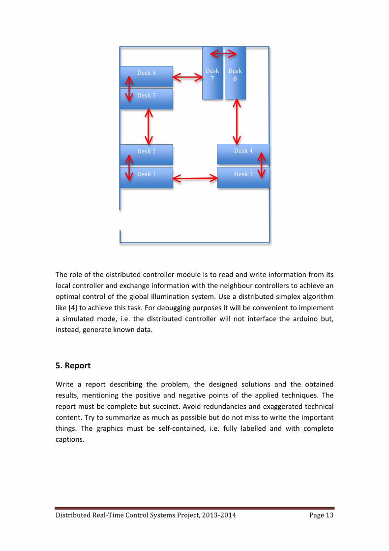
7. Write the distributed controllers to deploy to each machine in the network. These controllers should have limited connectivity i.e. should connect only to direct neighbours according to the following map:
Distributed Real-‐Time Control Systems Project, 2013-‐2014 Page 13
The role of the distributed controller module is to read and write information from its local controller and exchange information with the neighbour controllers to achieve an optimal control of the global illumination system. Use a distributed simplex algorithm like [4] to achieve this task. For debugging purposes it will be convenient to implement a simulated mode, i.e. the distributed controller will not interface the arduino but, instead, generate known data.
5. Report
Write a report describing the problem, the designed solutions and the obtained results, mentioning the positive and negative points of the applied techniques. The report must be complete but succinct. Avoid redundancies and exaggerated technical content. Try to summarize as much as possible but do not miss to write the important things. The graphics must be self-‐contained, i.e. fully labelled and with complete captions.
Desk 1
Desk 2
Desk 3
Desk 4
Desk 6
Desk 5
Desk 8
Desk 7
Distributed Real-‐Time Control Systems Project, 2013-‐2014 Page 14
6. References
[1] Occupancy-‐based illumination control of LED lighting sensors, D. Caicedo, A. Pandharipande and G. Leus, Lighting Research and Technology 43: 217, 2011.
[2] Daylight integrated illumination control of LED systems based on enhanced presence sensing, A. Pandharipande, D. Caicedo, Energy and Buildings 43, 944–950, 2011.
[3] Distributed Illumination Control With Local Sensing and Actuation in Networked Lighting Systems, A. Pandharipande, D. Caicedo, IEEE SENSORS JOURNAL, VOL. 13, NO. 3, MARCH 2013.
[4] A distributed simplex algorithm for degenerate linear programs and multi-‐agent assignments, M. Bürger, G. Notarstefano, F. Bullo, F. Allgöwer, Automatica 48, 2298–2304, 2012.
All papers available in the course web page.
– End of the project –