distribution automation smart feeders in a smart grid ... · 01/09/2011 · distribution automation...
TRANSCRIPT

Distribution Automation –Smart Feeders in a Smart Grid World
Distribution Management
S tBob Uluski
Systems
© 2010 Quanta Technology LLC
DMS Defined• Distribution Management System
A Decision Support System to assist theA Decision Support System to assist the control room and field operating personnel
with the monitoring and control of the l t i di t ib ti telectric distribution system Note: Not to be confused with
Demand Side Management (DSM)!
© 2010 Quanta Technology LLC
DMS Defined – What’s included?
• Basic operating tools– Distribution SCADA (DSCADA)Distribution SCADA (DSCADA)
– “Person in Charge” software tools• managing permits clearances safetymanaging permits, clearances, safety protection guarantees
• Generating switching orders
© 2010 Quanta Technology LLC

DMS Defined – What’s included?• Advanced Distribution Applications
– On line power flowp– Load forecasting (short and long term)– State estimation– Fault location– Distribution contingency analysis– Distribution “congestion management”– System optimization (e.g. Optimal Network
f )Reconfiguration)
© 2010 Quanta Technology LLC

DMS Defined – What’s included?DMS Defined What s included?
• May be a host for DAMay be a host for DA (feeder automation) applications DA Logic
Resides here
– Fault location isolation and service restoration (FLISR)
Control Center
Feeder Locations
(FLISR)
– Volt‐VAR optimization (VVO)
© 2010 Quanta Technology LLC

The DMS Concept at BC Hydro
DMS C������
�� BC H����
© 2010 Quanta Technology LLC

Topics
• DMS Functions pertaining to DA– On‐Line Power Flow (OLPF)– On‐Line Power Flow (OLPF)
– State estimation
– Fault Location
– Switch Order Management (SOM)
– Contingency Analysis
– Congestion management
• System Integration (Hahn)
© 2010 Quanta Technology LLC

State EstimationState Estimation• Objectives
l f– Topology verification– Estimation of loads– Validation of telemetered data– Load calibration
• A Data Consolidation Process– Take the advantages of sufficient measurement redundancy (M/N
> 1.5)Correct data errors due to– Correct data errors due to conflict/incorrect/inaccurate/asynchronous
– measurements• Candidate State Variables (independent variables)
– Voltages– Branch Currents– Nodal Injections
© 2010 Quanta Technology LLC

DMS State EstimationDMS State Estimation
• DMS State Estimation (SE) ‐ a procedure used toDMS State Estimation (SE) a procedure used to calculate the state of distribution system based on: – distribution system configuration (topology),
– real time measurements and
– customer load profiles – pseudo measurement
• Consists of:– Static state estimation
– Identification and re‐estimation of bad measurements and parameters
© 2010 Quanta Technology LLC
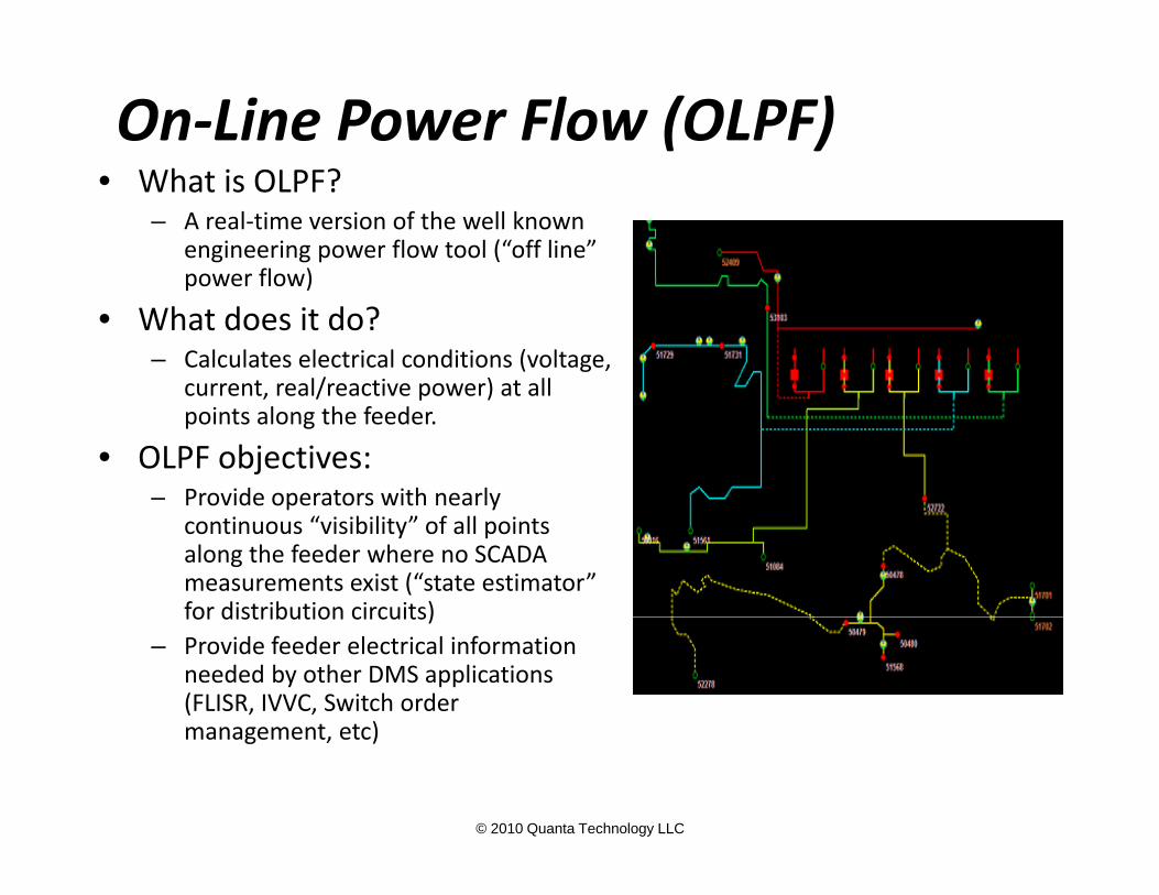
On‐Line Power Flow (OLPF)• What is OLPF?
– A real‐time version of the well known engineering power flow tool (“off line” power flow)power flow)
• What does it do?– Calculates electrical conditions (voltage,
current real/reactive power) at allcurrent, real/reactive power) at all points along the feeder.
• OLPF objectives:– Provide operators with nearlyProvide operators with nearly
continuous “visibility” of all points along the feeder where no SCADA measurements exist (“state estimator” for distribution circuits)for distribution circuits)
– Provide feeder electrical information needed by other DMS applications (FLISR, IVVC, Switch order management etc)
© 2010 Quanta Technology LLC
management, etc)

On‐Line Power Flowd k?• How does it work?
– Works in much the same way as the engineering tool
– Uses one of the many available iterative solution techniques:
• Newton Raphson, YBus, ZBus, Forward/Backward “ ”“Sweep”
– Must be able to handle radial circuit and “weakly meshed” circuit
N “W kl h d” h b f l• Note: “Weakly meshed” means there may be a few loops– Unlike off‐line engineering tool, OLPF results are scaled to match available real‐time measurements
S b t ti d f f d (b k i DSCADA)• Substation end of feeder (breaker via DSCADA)• Mid line measurements (recloser via feeder SCADA)• Handful of AMI measures from strategically‐placed measurements (distribution transformer, voltage at
© 2010 Quanta Technology LLC
measurements (distribution transformer, voltage at feeder extremities)

How DG is Modeled By DMS Vendors• Variations exist in the way the DMS vendors handle DG resources:
– Full regulating model• Generally the best approach fo modeling the dynamic behavior of the dg units under normal and
emergency• PQ type (fixed real and reactive power) or PV type (fixed real power and target regulating voltage)
– Negative Load Model• Can be profiled, such as CHP (combined heating and power) units. • Fault current contribution is not accounted for in fault‐level calculations• Cannot be the only source of power for de energized island• Cannot be the only source of power for de‐energized island
– No model – DER outputs captured by SCADA in real‐time• No guesswork regarding generator status and output• May not be able to determine fault current contribution without dynamic model• Not really suitable for outage planning and engineering analysis (study mode)Not really suitable for outage planning and engineering analysis (study mode)
– Three phase and single phase models• some vendors cannot handle single phase DER units, others can• Some require balanced 3 phase generator output, other models support unbalanced performance
• Conclusion:– Regulating Model (PQ or PV) is needed to properly model the effects of DG units under normal
and emergency conditions (e.g. fault contribution)– Not all DMS vendors support the necessary facilities for handling DG
© 2010 Quanta Technology LLC
– Need to ask detailed questions; and make decisions accordingly

On‐Line Power Flow Models• Feeder electrical model
– Unbalanced 3‐phase representation– Some DMS applications (especially IVVC) require modeling from substation transformer high side to distribution service transformerservice transformer
– Handle radial and weakly meshed circuits– Modeling of distributed generating resources
• Fully regulating model• Negative load
– Creating and maintaining the model• Via Geographic Information System (GIS) for large systems• Via existing engineering model or OMS• Manually (small systems only)
© 2010 Quanta Technology LLC
y ( y y)

On‐Line Power Flow Models• Load models
– OLPF solution requires load approximation for each distribution service transformer – Load Estimator function handles this
– Conventional approach – use load profileobtained via statistical load survey
© 2010 Quanta Technology LLC

Viewing OLPF results• Tabular display (SNC Lavalin)
© 2010 Quanta Technology LLC

Viewing OLPF results• Graphical display (Telvent)
© 2010 Quanta Technology LLC

Viewing OLPF results• Abnormal conditions (Areva)
© 2010 Quanta Technology LLC

Fault LocationObj i A i fi ld i i i i f l l i• Objective: Assist field crews in pinpointing fault location
• Fault distance provided by protective relay IEDs not accurate:
– Assumes homogeneous wire size/arrangement– Assumes homogeneous wire size/arrangement
– Fault impedance unknown
• DMS Approach:pp
– “Reverse short circuit” analysis
• Obtain fault magnitude and type (A, B, C, A‐B, etc) fro relay IED
• Determine possible fault locations using DMS short circuit analysis tool and associated feeder modelcircuit analysis tool and associated feeder model
• Determine electrical distance using reactance to fault –eliminate effects of mostly resistive fault impedance
© 2010 Quanta Technology LLC

Fault Location – DMS Reverse SCA hApproach
© 2010 Quanta Technology LLC

Switching Orders• Allows dispatcher to create, save, and print switching orders
• Dispatcher selects the switch and initiates the switching order menu item
• Switching order can include:– Date and time in and out– Type of operation– Permit to work (Permit number, issue time, cancellation
time)– Reason for order (planned outage, maintenance, test, etc.)
• Pre Switching Analysis
© 2010 Quanta Technology LLC
g y

Generation of Schematic Displays
© 2010 Quanta Technology LLC

Switch Order Management (SOM)
• In its simplest form, a computerized version of manual switch ordersswitch orders
• DMS version:
– Graphical interface to create switch orders manually
– Automatic creation of switch orders based on safety rules
ifi i f i hi d– Verification of switching orders
© 2010 Quanta Technology LLC

Switch Order Management
© 2010 Quanta Technology LLC

DMS Switching Plan
© 2010 Quanta Technology LLC

Switch Order Verificationf• “Simulates” execution of the switch order
• Verifies that simulated steps don’t create d i bl l i l di iundesirable electrical conditions
• Two Variations:– Maintenance planning mode (“day before”)– Near‐Real‐Time mode
© 2010 Quanta Technology LLC

Optimal Network ReconfigurationOptimal Network Reconfiguration• Objectives :
l f d l ( f f l l h d )– Minimize energy losses on feeder lines (time frame of multiple hours or days)– Balance loads among phases, feeders, substations, transformers– Plan outages for equipment or feeder section maintenance
• Seasonal OptimizationSeasonal Optimization– Goal => optimize topology for steady state operations
• Minimal power and energy losses• Maximum reliability• Best load balance• Best load balance• Best voltage profiles
• Near Real‐Time Optimization– Normal operations => Loss Optimization Mode– Emergency operations => Voltage Reduction Mode– Peak load shaving => MW Reduction Mode
© 2010 Quanta Technology LLC

Distribution Contingency AnalysisDistribution Contingency Analysis• Objectives :
N 1 Screening for outages on potential devices/segments– N‐1 Screening for outages on potential devices/segments– Find out the critical outages that could result in key customers out of services
d di l i• Recommend remedial actions– Controls:
• Reconfigure the feeder network• Reduce load, use local resources, etc.
– Control Constraints:• Voltage Hi/Lo operation limits at each node and at any time interval
• Loading limit at each line section, switch, Xfmr at any time interval
© 2010 Quanta Technology LLC

DER Congestion ManagementDER Congestion Management• A function for monitoring, controlling,
scheduling, and managing Distributed g, g gEnergy Resources (DER) and Demand Response (DR).
• Provides two‐way visibility between retail/demand‐side resources, wholesale energy markets, and all the intermediate levels of the business hierarchylevels of the business hierarchy
• Manages diverse types of demand‐side resources – from dispatchable, voluntary, price responsive and dynamic tariff‐based DR programs to distributed generation, storage, and PEV/PHEV g , /
• Forecasts and schedules DER and DR in support system and market operations
• Allows participation of DER and DR in Energy, Capacity, and various Ancillary Services markets
• Monitors distribution grid condition affected by DR/DER, including equipment loading constraints, voltage max/min constraints per phase, phase imbalances, and use distributed generation for satisfying voltage constraints
© 2010 Quanta Technology LLC
voltage constraints

Emerging trend – Integration of / lDMS/OMS Functionality
• There are some distinct differences between DMS and OMS– DMS generally has more real time monitoring and control functionality than OMSfunctionality than OMS
– OMS tends to have more customer‐oriented functionality and crew dispatching capabilities
• There is a considerable amount of overlap between DMS and OMS
M i t f t d t di t ib ti t t l– Maintenance of an up to date distribution system topology model (a huge task!)
– Generation and simulation of switching orders
© 2010 Quanta Technology LLC

Benefits of DMS/OMS IntegrationBenefits of DMS/OMS Integration
• Automatic capture of all automated restoration device operations– Reduced number of customers affected by the sustained outage– Reduced time to restore sustained outage due less time spent on manual
sectionalizingg
• Accurate accounting of outage durations as experienced by the customer (eliminate dependency on crew for outage start/stop time)
• DSCADA/DA/OMS operators have seamless view of DA schematic circuits & OMS geospatial circuits
• Operators have base platform for future advanced applications to be added – Switching & Tagging, System Estimation, IVVC etc
© 2010 Quanta Technology LLC

Emerging trend – Integration of / lDMS/OMS Functionality
• Traditional DMS/DSCADA vendors have or areTraditional DMS/DSCADA vendors have or are developing OMS solutions
• Traditional OMS vendors have or are• Traditional OMS vendors have or are developing DMS/DSCADA solutions
Will b h d di i i h DMS• Will become even harder to distinguish DMS and OMS!
© 2010 Quanta Technology LLC