distribution of gps-data via internet
TRANSCRIPT
LMV-report 2004:01
Reports in Geodesy and Geographical Information Systems
Distribution of GPS-datavia Internet
Martin PeterzonThesis work
Gävle 2004
L A N T M Ä T E R I E T

Abstract
The progress of easy mobile Internet access has triggered research activities around newmethods of distributing GPS-data in high accuracy positioning systems. National LandSurvey of Sweden, Lantmäteriet, operates a network of permanent reference stations,SWEPOS™ , where Internet-distribution of GPS-data to users is a subject of interest. Thispaper shows that such a distribution is possible and that there are many benefits in thetechnique. The main focus is on the real-time protocol Ntrip, developed for GPS-data –its components and data format.
A test system for Ntrip and an application that monitors the quality of DGPS-data wasimplemented and tested at Lantmäteriet, showing promising results with low latencies,good reliability and simple installation procedures. Ntrip is flexible; hence twoapproaches of integration with the present SWEPOS system and three solutions of thecommunication between different Ntrip system are proposed. Cost aspects are alsoinvestigated. With good Internet provider contracts and the new, compact data format inuse, Internet distribution will become more cost-efficient than the systems used today.

Preface
This report describes the thesis work that finishes my Master of Science in InformationTechnology Engineering at Uppsala University. The work has been carried out at theGeodetic Research Department at the Nation Land Survey of Sweden, Lantmäteriet, inGävle.
I would like to thank my supervisors Gunnar Hedling and Bo Jonsson, along witheverybody else at the Geodetic Research Department, for being friendly and helpful. Iwould also like to thank Georg Weber, BKG, for active participation in the thesis; GöranArrhen, Trimble, for software support; and my examiner Ivan Christoff at the Departmentof Information Technology, Uppsala University, for valuable feedback.
Uppsala, January 2004
Martin Peterzon

Table of Contents
1. Introduction........................................................................................................11.1. Background .................................................................................................... 11.2. Problems ........................................................................................................ 11.3. Disposition ..................................................................................................... 1
2. GPS and Networks..............................................................................................22.1. GPS and Corrections ....................................................................................... 22.2. Network RTK................................................................................................. 22.3. SWEPOS ....................................................................................................... 32.4. Data Flow....................................................................................................... 42.5. TCP/IP........................................................................................................... 42.6. Distribution of Corrections............................................................................... 5
3. Networked Transport of RTCM via Internet Protocol........................................53.1. System Overview............................................................................................ 63.2. NtripCaster..................................................................................................... 73.3. NtripSource .................................................................................................... 83.4. NtripServer..................................................................................................... 83.5. NtripClient...................................................................................................... 83.6. Messages........................................................................................................ 9
4. Test System.........................................................................................................94.1. Local RTCM Source ..................................................................................... 104.2. Stationary BKG Client................................................................................... 104.3. Mobile BKG Client ....................................................................................... 114.4. Trimble ACU Client...................................................................................... 114.5. Latency Measurements.................................................................................. 114.6. Conclusions .................................................................................................. 14
5. Broadcast corrections .......................................................................................145.1. Broadcast versus Virtual Reference Station..................................................... 145.2. RTCM SAPOS............................................................................................. 165.3. Broadcast in GPSNet..................................................................................... 16
6. Integration in the Present System .....................................................................166.1. Local NtripCaster.......................................................................................... 166.2. RTCM Sources............................................................................................. 176.3. New Rovers.................................................................................................. 18
7. Cost and Data Amount .....................................................................................197.1. Frequency..................................................................................................... 197.2. RTCM Size................................................................................................... 197.3. Cost of GSM and GPRS ................................................................................ 207.4. Future Considerations.................................................................................... 217.5. Conclusions .................................................................................................. 22

8. Communication Between NtripCasters.............................................................228.1. Modified NtripClient ..................................................................................... 228.2. Combined NtripServer and NtripClient ........................................................... 238.3. Modified NtripCaster .................................................................................... 24
9. Monitoring the Quality of Corrections..............................................................259.1. Correction Quality Parameters ....................................................................... 259.2. Components and Communication ................................................................... 269.3. Implementation ............................................................................................. 27Local Test............................................................................................................ 27
10. Conclusions.......................................................................................................28
11. References ........................................................................................................30
Appendix A – Configuration of the built-in NtripClient in Trimble SC..................32
Appendix B – Size of RTCM 2.3 data packets ........................................................33
Appendix C – Setting up Logger and Monitor programs .......................................35
1
1. Introduction
1.1. Background
SWEPOS™ is a network of permanent reference stations operated by National LandSurvey of Sweden, Lantmäteriet, providing high accuracy positioning and navigation forscientific and practical use. Today distribution of GPS-data to users is handled with FMradio, geostationary satellites, GSM and FTP, but there is an increasing interest in usingInternet as communication channel. With good mobile coverage and cost-effectivemethods it is a distribution technique for the future.
Networked Transport of RTCM via Internet Protocol (Ntrip) is an application levelprotocol for distribution of GPS-data. Test systems in Germany indicate that the protocolcould also be efficiently implemented in SWEPOS. A study of the possibilities to useInternet distribution with Ntrip at Lantmäteriet is of great interest.
1.2. Problems
This paper will present a possible establishment of Internet distribution and Ntrip withinSWEPOS. Several aspects are considered. Issues like (1) hardware and softwarerequirements, (2) distribution techniques, (3) integration with present system,(4) flexibility, and (5) costs will be discussed. With the test system that was set-up, it isalso possible to answer questions concerning (6) packet latencies and (7) performance ofthe protocol. An implementation of an application that monitors data quality in theSWEPOS network RTK system shows (8) a realization of a computer network systemhandling GPS-data.
1.3. Disposition
Section 2 gives an introduction to GPS, Network RTK and existing positioning systems.It also describes some basics in computer communication. In section 3 the Ntrip protocolis introduced, followed by a description, in section 4, of a test system, with details aboutdifferent configurations and latency measurements. Section 5 deepens the discussion ofbroadcast methods of corrections, and section 6 suggests different approaches that can beused in the integration of the present system. Packet sizes of different correctionmessages are illustrated in section 7, followed by a comparison of costs of Internetdistribution and methods used today. Section 8 suggests different approaches forcommunication between NtripCasters – the centers of the distribution. Animplementation of an application that monitors the quality of Network RTK corrections isdescribed in section 9. This is an example of a service that can use computer networks forGPS-data distribution. Finally, in section 10, the paper is summarized and conclusions arepresented.

2
2. GPS and NetworksTo improve the accuracy in GPS (Global Positioning Systems) positioning severaldifferent methods exists. They are all based on information sent between themeasurement equipment and other devices, such as permanent reference stations. Belowis a short description of GPS and some of these techniques. Since this paper is aboutdistribution of data via computer networks, a brief description of basic computercommunication is also included.
2.1. GPS and Corrections
GPS is an American positioning and navigation system consisting of 29 satellites(January 2004). It was developed mainly for military purposes. By knowing the distanceto at least four satellites it is possible to calculate a position and a time offset almostanywhere on earth. If two GPS-receivers have visual sight of the same satellites, arelative positioning can be performed, where the differences between the stations aremeasured. This reduces most error sources. In relative positioning, usually one station isat a fixed location (the base) and the other is moved between points to be determined (therover).
The two most common methods for real-time relative positioning are called DGPS(Differential GPS) and RTK (Real-Time Kinematic). DGPS uses signal travel timebetween satellite and receiver to calculate the distance, while RTK also uses a carrierphase and the distance is measured in number of full phase cycles plus a decimal part ofone period. The accuracy is 0.5 - 2 meter for DGPS and 1 - 5 centimeter for RTK.
There are a number of error sources in a GPS measurement. Errors in satellite orbit andclock are eliminated in relative positioning, while ionospheric, tropospheric, and receiverclock errors still remain, but are reduced.
For survey positioning, and many other types of positioning, the accuracy that one getsfrom relative methods is necessary. A network of fixed GPS-receivers, which can be usedas bases, is therefor useable. Such a network exists in Sweden: SWEPOS. The bases arecalled permanent reference stations and users have the possibility to utilize them as theirbase in relative positioning. Messages sent from a reference station to a rover are calledcorrections. The most common data format for corrections is RTCM – a recommendedstandard developed by the Radio Technical Commission for Maritime Services [R01].
2.2. Network RTK
There has been an increasing interest in the concept of Network RTK during the lastyears. Measurements can be done with improved integrity, continuity and accuracy in amore sparse network of stations. It also leads to productivity improvements – since onlyone receiver is necessary and no temporary base station have to be established – and thecost of establishment and maintenance is reduced. For a working Network RTKconfiguration the stations have to be connected to a control center with a data link.
The basic idea is to use information from all reference stations in the network, instead ofthe closest only (as in DGPS and RTK). One reference station works as a central unit,collecting data from all the stations in the network. By using information from the wholearea, it is possible to use models that make better estimates of the errors. The corrections
3
can then be sent from the central reference station – here called the control center – torovers in the network.
Basically there are two different methods for distributing the corrections in NetworkRTK: VRS (Virtual Reference Station) and Broadcast. Both of these are described below.
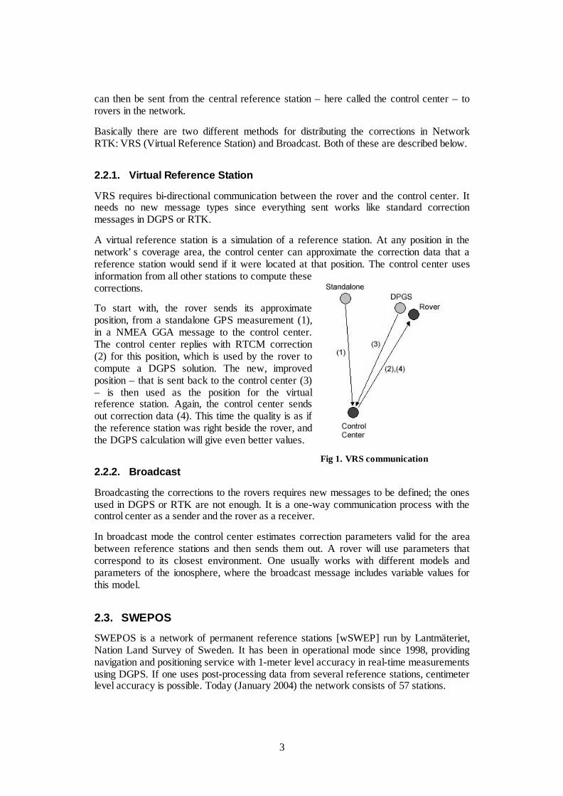
2.2.1. Virtual Reference Station
VRS requires bi-directional communication between the rover and the control center. Itneeds no new message types since everything sent works like standard correctionmessages in DGPS or RTK.
A virtual reference station is a simulation of a reference station. At any position in thenetwork’s coverage area, the control center can approximate the correction data that areference station would send if it were located at that position. The control center usesinformation from all other stations to compute thesecorrections.
To start with, the rover sends its approximateposition, from a standalone GPS measurement (1),in a NMEA GGA message to the control center.The control center replies with RTCM correction(2) for this position, which is used by the rover tocompute a DGPS solution. The new, improvedposition – that is sent back to the control center (3)– is then used as the position for the virtualreference station. Again, the control center sendsout correction data (4). This time the quality is as ifthe reference station was right beside the rover, andthe DGPS calculation will give even better values.
2.2.2. Broadcast
Broadcasting the corrections to the rovers requires new messages to be defined; the onesused in DGPS or RTK are not enough. It is a one-way communication process with thecontrol center as a sender and the rover as a receiver.
In broadcast mode the control center estimates correction parameters valid for the areabetween reference stations and then sends them out. A rover will use parameters thatcorrespond to its closest environment. One usually works with different models andparameters of the ionosphere, where the broadcast message includes variable values forthis model.
2.3. SWEPOS
SWEPOS is a network of permanent reference stations [wSWEP] run by Lantmäteriet,Nation Land Survey of Sweden. It has been in operational mode since 1998, providingnavigation and positioning service with 1-meter level accuracy in real-time measurementsusing DGPS. If one uses post-processing data from several reference stations, centimeterlevel accuracy is possible. Today (January 2004) the network consists of 57 stations.
Fig 1. VRS communication
4
During the last years there have been several pre-study projects on Network RTK inSweden [JHW03]. These studies have shown very promising results, both concerning theperformance and user interest; and in January 2004 the service SWEPOS Network RTKbecame available to the public. At present the network covers southern Sweden, the areaaround Gothenburg and the Mälardalen region.
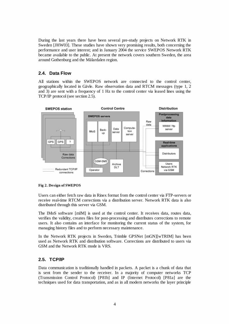
2.4. Data Flow
All stations within the SWEPOS network are connected to the control center,geographically located in Gävle. Raw observation data and RTCM messages (type 1, 2and 3) are sent with a frequency of 1 Hz to the control center via leased lines using theTCP/IP protocol (see section 2.5).
Fig 2. Design of SWEPOS
Users can either fetch raw data in Rinex format from the control center via FTP-servers orreceive real-time RTCM corrections via a distribution server. Network RTK data is alsodistributed through this server via GSM.
The IMoS software [mIM] is used at the control center. It receives data, routes data,verifies the validity, creates files for post-processing and distributes corrections to remoteusers. It also contains an interface for monitoring the current status of the system, formanaging history files and to perform necessary maintenance.
In the Network RTK projects in Sweden, Trimble GPSNet [mGN][wTRIM] has beenused as Network RTK and distribution software. Corrections are distributed to users viaGSM and the Network RTK mode is VRS.
2.5. TCP/IP
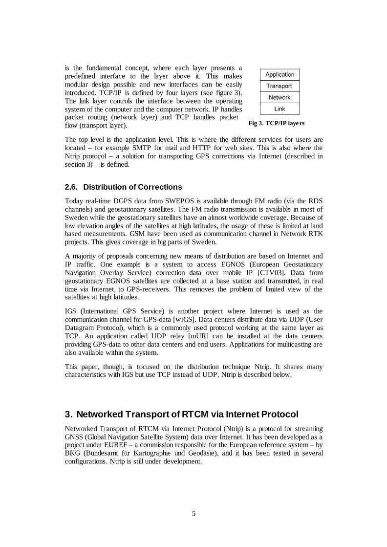
Data communication is traditionally handled in packets. A packet is a chunk of data thatis sent from the sender to the receiver. In a majority of computer networks TCP(Transmission Control Protocol) [P81b] and IP (Internet Protocol) [P81a] are thetechniques used for data transportation, and as in all modern networks the layer principle
5
is the fundamental concept, where each layer presents apredefined interface to the layer above it. This makesmodular design possible and new interfaces can be easilyintroduced. TCP/IP is defined by four layers (see figure 3).The link layer controls the interface between the operatingsystem of the computer and the computer network. IP handlespacket routing (network layer) and TCP handles packetflow (transport layer).
The top level is the application level. This is where the different services for users arelocated – for example SMTP for mail and HTTP for web sites. This is also where theNtrip protocol – a solution for transporting GPS corrections via Internet (described insection 3) – is defined.
2.6. Distribution of Corrections
Today real-time DGPS data from SWEPOS is available through FM radio (via the RDSchannels) and geostationary satellites. The FM radio transmission is available in most ofSweden while the geostationary satellites have an almost worldwide coverage. Because oflow elevation angles of the satellites at high latitudes, the usage of these is limited at landbased measurements. GSM have been used as communication channel in Network RTKprojects. This gives coverage in big parts of Sweden.
A majority of proposals concerning new means of distribution are based on Internet andIP traffic. One example is a system to access EGNOS (European GeostationaryNavigation Overlay Service) correction data over mobile IP [CTV03]. Data fromgeostationary EGNOS satellites are collected at a base station and transmitted, in realtime via Internet, to GPS-receivers. This removes the problem of limited view of thesatellites at high latitudes.
IGS (International GPS Service) is another project where Internet is used as thecommunication channel for GPS-data [wIGS]. Data centers distribute data via UDP (UserDatagram Protocol), which is a commonly used protocol working at the same layer asTCP. An application called UDP relay [mUR] can be installed at the data centersproviding GPS-data to other data centers and end users. Applications for multicasting arealso available within the system.
This paper, though, is focused on the distribution technique Ntrip. It shares manycharacteristics with IGS but use TCP instead of UDP. Ntrip is described below.
3. Networked Transport of RTCM via Internet ProtocolNetworked Transport of RTCM via Internet Protocol (Ntrip) is a protocol for streamingGNSS (Global Navigation Satellite System) data over Internet. It has been developed as aproject under EUREF – a commission responsible for the European reference system – byBKG (Bundesamt für Kartographie und Geodäsie), and it has been tested in severalconfigurations. Ntrip is still under development.
Fig 3. TCP/IP layers
6
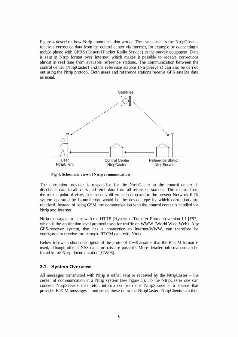
Figure 4 describes how Ntrip communication works. The user – that is the NtripClient –receives correction data from the control center via Internet, for example by connecting amobile phone with GPRS (General Packet Radio Service) to the survey equipment. Datais sent in Ntrip format over Internet, which makes it possible to receive correctionsalmost in real time from available reference stations. The communication between thecontrol center (NtripCaster) and the reference stations (NtripServers) can also be carriedout using the Ntrip protocol. Both users and reference stations receive GPS satellite dataas usual.
Fig 4. Schematic view of Ntrip communication
The correction provider is responsible for the NtripCaster at the control center. Itdistributes data to all users and fetch data from all reference stations. This means, fromthe user’s point of view, that the only difference compared to the present Network RTKsystem operated by Lantmäteriet would be the device type by which corrections arereceived. Instead of using GSM, the communication with the control center is handled viaNtrip and Internet.
Ntrip messages are sent with the HTTP (Hypertext Transfer Protocol) version 1.1 [F97],which is the application level protocol used for traffic on WWW (World Wide Web). AnyGPS-receiver system, that has a connection to Internet/WWW, can therefore beconfigured to receive for example RTCM data with Ntrip.
Below follows a short description of the protocol. I will assume that the RTCM format isused, although other GNSS data formats are possible. More detailed information can befound in the Ntrip documentation [GW03].
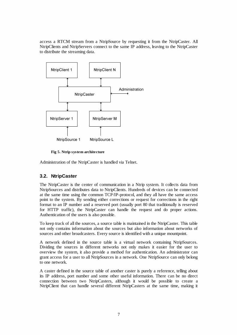
3.1. System Overview
All messages transmitted with Ntrip is either sent or received by the NtripCaster – thecenter of communication in a Ntrip system (see figure 5). To the NtripCaster one canconnect NtripServers that fetch information from one NtripSource – a source thatprovides RTCM messages – and sends these on to the NtripCaster. NtripClients can then
7
access a RTCM stream from a NtripSource by requesting it from the NtripCaster. AllNtripClients and NtripServers connect to the same IP address, leaving to the NtripCasterto distribute the streaming data.
Fig 5. Ntrip system architecture
Administration of the NtripCaster is handled via Telnet.
3.2. NtripCaster
The NtripCaster is the center of communication in a Ntrip system. It collects data fromNtripSources and distributes data to NtripClients. Hundreds of devices can be connectedat the same time using the common TCP/IP-protocol, and they all have the same accesspoint to the system. By sending either corrections or request for corrections in the rightformat to an IP number and a reserved port (usually port 80 that traditionally is reservedfor HTTP traffic), the NtripCaster can handle the request and do proper actions.Authentication of the users is also possible.
To keep track of all the sources, a source table is maintained in the NtripCaster. This tablenot only contains information about the sources but also information about networks ofsources and other broadcasters. Every source is identified with a unique mountpoint.
A network defined in the source table is a virtual network containing NtripSources.Dividing the sources in different networks not only makes it easier for the user tooverview the system, it also provide a method for authentication. An administrator cangrant access for a user to all NtripSources in a network. One NtripSource can only belongto one network.
A caster defined in the source table of another caster is purely a reference, telling aboutits IP address, port number and some other useful information. There can be no directconnection between two NtripCasters, although it would be possible to create aNtripClient that can handle several different NtripCasters at the same time, making it
8
visible for the users as if the NtripCasters are co-operating (for more details, seesection 8.1).
Telnet is used for administration of the NtripCaster. The administrator can, for example,allow and deny clients and sources, monitor different statistics and set authorization.
Technically a NtripCaster is - in most aspects – an HTTP server supporting a subset ofHTTP requests and responses adjusted to streaming data. In terms of the standardclient/server terminology a NtripCaster works as a server, while both a NtripClient and aNtripServer works as clients. This means that the NtripCaster is always the passive devicein the connection, the one that is contacted.
3.3. NtripSource
A NtripSource is a geographically stationary point that provides continuous, streamingRTCM data. This data is then sent to the NtripServer, which is taking care of the transferto the NtripClient.
A NtripSource is identified by a unique mountpoint in the source table of a NtripCaster. Itis by this mountpoint that a NtripClient can get access to the source. The mountpoint isthe single thing identifying the source and is the key value when establishing a RTCMstream through the NtripCaster. The source table also specifies the RTCM format andsome other characteristics.
3.4. NtripServer
A NtripServer receives RTCM data from a NtripSource and sends it to the NtripCaster.When setting up the NtripServer one needs to know a mountpoint and a password; bothare provided by the administrator of the NtripCaster. This information can not be sentthrough the Ntrip system, but have to be delivered by some other medium – for examplee-mail.
Because TCP is able to detect broken connections, a NtripServer can be programmed todeal with such events, for example by trying to reconnect. TCP also makes it possible fordata to travel through most parts of Internet without firewalls interrupting the traffic.
An example of a NtripServer implementation in Windows is provided by BKG inGermany [wBKG].
3.5. NtripClient
The NtripClient is the component that is installed in the users GPS receiving devicesystem, for example in a pocket PC. It requests data from a NtripCaster by asking for astream from a specific mountpoint, given by the source table it has received from theNtripCaster. Depending on the implementation of the NtripClient this stream can behandled in different ways. For example one could transfer it with a serial cable to a GPS-receiver or monitor it on the computer directly using a RTCM interpreting application.
As with the NtripServer, the NtripClient can be programmed to deal with brokenconnections using the support for this in TCP.
9
For some GPS techniques, such as VRS,the NtripClient has to be able to send itsposition to the NtripCaster. This issupported in Ntrip with the possibility tosend NMEA GGA strings attached to aHTTP message. It is specified in the sourcetable whether the NtripSource use NMEAmessages or not.
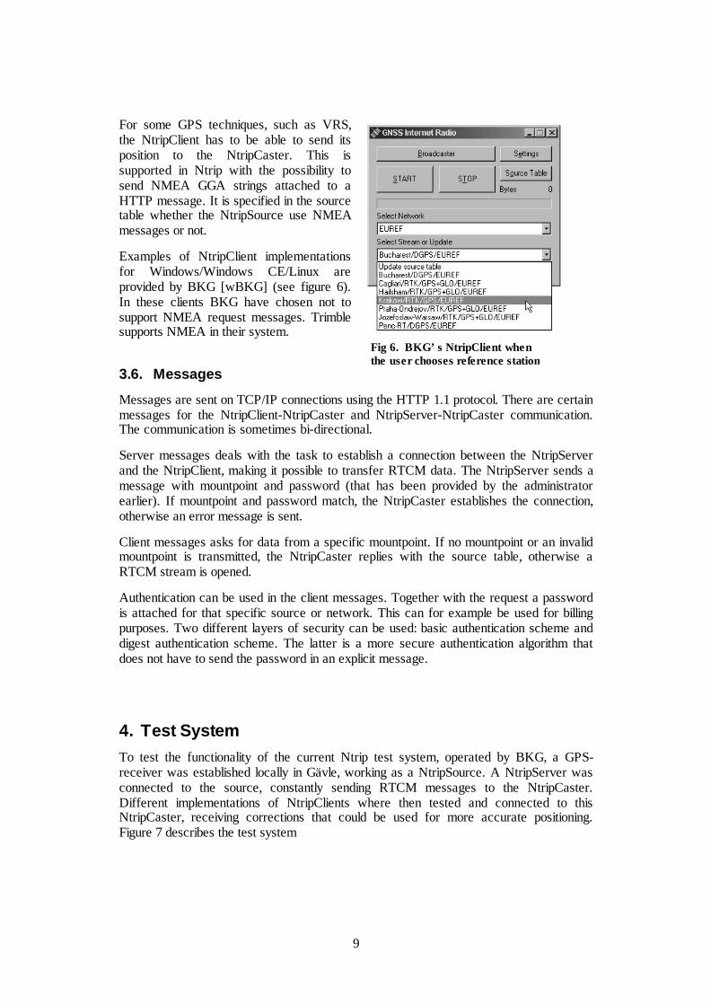
Examples of NtripClient implementationsfor Windows/Windows CE/Linux areprovided by BKG [wBKG] (see figure 6).In these clients BKG have chosen not tosupport NMEA request messages. Trimblesupports NMEA in their system.
3.6. Messages
Messages are sent on TCP/IP connections using the HTTP 1.1 protocol. There are certainmessages for the NtripClient-NtripCaster and NtripServer-NtripCaster communication.The communication is sometimes bi-directional.
Server messages deals with the task to establish a connection between the NtripServerand the NtripClient, making it possible to transfer RTCM data. The NtripServer sends amessage with mountpoint and password (that has been provided by the administratorearlier). If mountpoint and password match, the NtripCaster establishes the connection,otherwise an error message is sent.
Client messages asks for data from a specific mountpoint. If no mountpoint or an invalidmountpoint is transmitted, the NtripCaster replies with the source table, otherwise aRTCM stream is opened.
Authentication can be used in the client messages. Together with the request a passwordis attached for that specific source or network. This can for example be used for billingpurposes. Two different layers of security can be used: basic authentication scheme anddigest authentication scheme. The latter is a more secure authentication algorithm thatdoes not have to send the password in an explicit message.
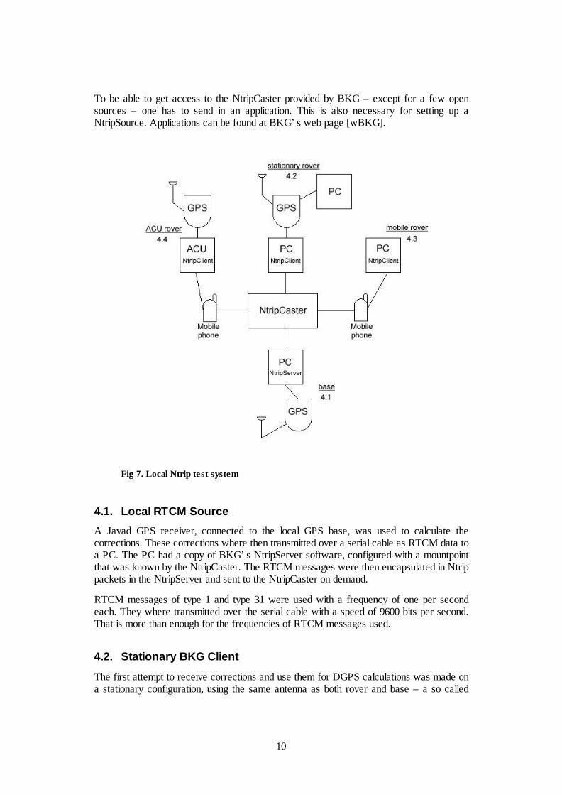
4. Test SystemTo test the functionality of the current Ntrip test system, operated by BKG, a GPS-receiver was established locally in Gävle, working as a NtripSource. A NtripServer wasconnected to the source, constantly sending RTCM messages to the NtripCaster.Different implementations of NtripClients where then tested and connected to thisNtripCaster, receiving corrections that could be used for more accurate positioning.Figure 7 describes the test system
Fig 6. BKG’s NtripClient whenthe user chooses reference station
10
To be able to get access to the NtripCaster provided by BKG – except for a few opensources – one has to send in an application. This is also necessary for setting up aNtripSource. Applications can be found at BKG’s web page [wBKG].
Fig 7. Local Ntrip test system
4.1. Local RTCM Source
A Javad GPS receiver, connected to the local GPS base, was used to calculate thecorrections. These corrections where then transmitted over a serial cable as RTCM data toa PC. The PC had a copy of BKG’s NtripServer software, configured with a mountpointthat was known by the NtripCaster. The RTCM messages were then encapsulated in Ntrippackets in the NtripServer and sent to the NtripCaster on demand.
RTCM messages of type 1 and type 31 were used with a frequency of one per secondeach. They where transmitted over the serial cable with a speed of 9600 bits per second.That is more than enough for the frequencies of RTCM messages used.
4.2. Stationary BKG Client
The first attempt to receive corrections and use them for DGPS calculations was made ona stationary configuration, using the same antenna as both rover and base – a so called
11
zero baseline. A PC connected to Internet ran the Windows NtripClient provided byBKG, and sent its output on a serial cable to a Javad receiver. The Javad receiver alsofetched GPS data, and with the software PCView [mPV] installed on another PC this datacould be viewed.
The traffic could then be logged with PCView software, for example by monitoringNMEA GGA messages in the GRIL interface [mGR]. Another way of logging is to catchthe RTCM packets when they leave the NtripClient. This was done with the “RTCMControl Program for Ntrip GNSS” for the latency measurements. The program isprovided by BKG.
4.3. Mobile BKG Client
An Ericsson T39 mobile phone was connected to Internet with Telia GPRS. The Internettraffic was then transmitted to a laptop via infrared communication, and an installation ofBKG’s NtripClient picked up the Ntrip packets and sent them in RTCM format to theRTCM Control Program.
This configuration was used for measurements of latencies of the mobile communication.
4.4. Trimble ACU Client
The Survey Controller (SC), version 10.71, in Trimble’s ACU has a built-in NtripClient.It can download the source table of a NtripCaster and let the user browse among thesources, choosing which station to use. The client also supports authentication of theusers. It can handle DGPS, RTK and SAPOS (a broadcast technique for Network RTK,see section 5.2). Earlier versions of the SC only includes support for receiving Internetcorrections, but not for the Ntrip protocol.
Windows CE is the operating system in the ACU.
With the built-in NtripClient it is easy to set-up the ACU for receiving corrections from aNtripCaster – one only needs an Internet connection. The same mobile phone as abovewas used for this test system. The communication between the phone and the ACU is inBluetooth.
The ACU was connected to a Trimble RTK 5700 GPS receiver – that is also operatedfrom the ACU – and calculation of the corrected GPS data is done in SC. Presentationand logging of the data is also taken care of by the SC.
See appendix A for information on how to configure the ACU for Ntrip.
4.5. Latency Measurements
Time latencies of TCP/IP-packets at Internet can be unpredictable and vary from time totime. You can never be sure that a packet will arrive before a predefined time limit, andbecause latencies are critical for RTCM data this is an important aspect to consider if onewants to send corrections through Internet. Congestion – that is when there is too muchtraffic at Internet, with the result of reduced throughput or limited possibilities to connectat all – will be a problem as long as Internet works as it does today. These problems can
12
be reduced though by good, reliable connections and by minimizing the amount of datathat is sent.
4.5.1. Equipment and Implementation
Two latency tests have been made for this report. One with a stationary Ethernet line(using the local area network (LAN)), and one with a GPRS connection (using anEricsson T39 mobile phone with Telia Mobile OnLine/GPRS). The Windows NtripClientprovided by BKG was connected to the NtripCaster in BKG’s test system in Frankfurt. Itreceived data from the NtripServer that was set up in Gävle, which means that the packetstraveled back and forth to Frankfurt.
To monitor the RTCM traffic and its latencies the software “RTCM Control Program forNtrip GNSS”, version 2.0 was used [wBKG]. Latency calculations in the program aremade comparing the modified z-count in a RTCM message to the internal clock set atlocal time. Leap seconds (difference between GPS time and GMT time) are softwarehandled, and since the time stamp only has a span of one hour, time zone does not matter.The modified z-count has a resolution of 0.6 seconds, therefore the time that is measuredis not exact and it is not necessary that the local computer time are absolutelysynchronized with the correct time. The local time used in the tests may be wrong by afew tenth of a second.
The total amount of data received was approximately 300 bytes per second. Thecapacities of both communication methods are more than sufficient to deal with thisamount of data.
4.5.2. Results
The latencies were measured 7 of October 2003 between 15.00 and 15.30. This is thetime when local network activity is at its peak. No similar information have beenavailable for Telia’s GPRS. It is likely that the network down to Germany is relativelybusy at this time. Latency measurements have also been performed during night-time inthe LAN only. These show similar characteristics as the day-time measurement.
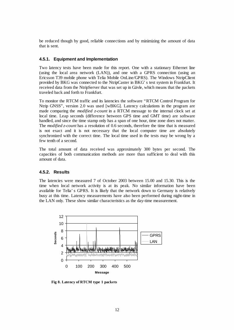
Fig 8. Latency of RTCM type 1 packets
0
2
4
6
8
10
12
0 100 200 300 400 500Message
Sec
onds GPRS
LAN
13
In figure 8 are the approximated latencies in seconds from 10 minutes of traffic. Duringthe tests both RTCM type 1 and RTCM type 31 was sent with a frequency of one persecond. Obviously the latency values are almost the same for both types and thereforeonly the graph for RTCM type 1 is plotted here. Note that these tests have not beenperformed at the same time (although within the same half an hour of the day), andshould not be compared message to message. It is the overall performance that isinteresting.
The latency mean of the LAN route is approximately 1.4 seconds and the latency mean ofthe GPRS route is approximately 2.9 seconds. Note that the difference between the valuescan be considered rather correct because they have the same error in the time variable.The actual mean can be a few tenth of a second in any direction. The effect of the z-counts resolution is cancelled in the mean.
4.5.3. Geographic Location
When using a local installation of a NtripCaster the packets get a vastly shortergeographic distance to travel. Tests in October 2003 (using ping) demonstrate that theapproximate travel time back and forth to the NtripCaster in Germany is about 0.5seconds. In pure time, this is not much of an improvement (because the travel times arealready low), but a more important aspect of a closer located NtripCaster is the reducedrisk that something goes wrong during the transportation. Every router the packet has topass increases the chance of loss or heavy latencies. When using a local NtripCaster onlya few routers have to be passed while there are about 15 routers on the way down to theNtripCaster in Frankfurt today.
It is a large project to get statistics of differences in stability of connections depending onlocation, but one can say that a local NtripCaster is a more reliable option that willgenerate less latencies.
4.5.4. Latency Differences
An obvious observation is that latency time of the LAN route is less than the GPRS route.This is not a surprise because wireless communication is generally slower and also needto pass more data routers when transforming from GPRS signals to line based Internettraffic. A difference of 1.5 seconds is realistic.
One can also observe that the latencies for the LAN route do not vary as much as theGPRS route. The oscillation of the LAN graph is probably more depending on theresolution of the modified z-count than the different packet travel times in the net. Thisresolution does not fully explain the differences for GPRS – those vary more than 0.6seconds. One can say that the normal performance – that is when there are no problems inthe network – for LAN is more stable than GPRS, but still GPRS seems rather stable andonly vary within a one second span, approximately.
LAN is also more secure when trying to avoid peaks with longer latencies. Peaks areusually a result of high amount of data traffic during a short period. There is only onepeak with the LAN route while there are a few with the GPRS route. From only tenminutes of traffic one should not make too certain conclusions about this, but it is quitelikely that this would be the case for a longer test period too. More things disturb a GPRSpacket than a LAN packet, and more frequent longer latencies can therefore be expected.
14
The latencies are not that bad though. Not even in the worst cases. Over an extendedperiod there would probably be some longer latencies, but as long as several packets in arow does not get these latencies it does not become a problem. A relatively steady streamof correction is the most important goal. One packet now and then can get delayedwithout decreasing the quality noticeable. That is the case here.
Heavier congestion on the net, or a server that has problems sending its corrections, willhappen, but this is hard to prevent and it will probably occur seldom. One way to reducethis is to have short geographic distances between the components.
4.6. Conclusions
This test system shows that it is possible to distribute GPS-data via Internet and that Ntripis a useful protocol for doing so. Because companies that provide GPS-receivers tends tominimize the users possibilities to make more advanced settings of the instruments it cansometimes be rather cumbersome to make the client/rover working. If Ntrip becomeswidely used this will probably not be a problem since the companies will adapt the userinterfaces to how their instruments are used in real world implementations.
Given that Ntrip is flexible and open it is relatively easy to build applications that suitsspecial needs. By following the specification the application will be able to communicatewith any possible NtripCaster. This is also true for the NtripServer side.
From the latency tests one should not make too certain conclusions, but the givenmeasurements looks promising and they are within acceptable time limits. For moreconfident conclusions one have to make latency tests under more realistic circumstances.
5. Broadcast correctionsThe ongoing Network RTK project in SWEPOS is using VRS to distribute corrections,but there have been interest in other broadcasting techniques too. Broadcast projects havebeen carried out at Lantmäteriet before (project New RTK). When the idea came up itwas rather with FM distribution in mind – since that is one-way communication – but itcan be interesting for Internet distribution too. Broadcasting is already used for manyapplications on Internet.
Test systems, that use different distribution methods, have been developed to get a goodapproximation of the GPS error in the whole network area. RTCM SAPOS [WB02] isone example of this. Since there is no standardized RTCM message that can handlebroadcast yet, the different methods used are hard to overlook. RTCM SC-104 has thetask to define a standard for broadcast distribution as a part of the coming RTCMstandard. Earliest in the end of 2004 their work is supposed to be ready.
5.1. Broadcast versus Virtual Reference Station
VRS is the most relevant technique to compare broadcast with. They both use severalconnected reference stations, and they both have one reference station working as a
15
control center. The difference is in which way the corrections are distributed and whatkind of information they contain.
In a Trimble paper [LVC03] the two methods have been compared. It points out that theburden of computation is shifted from the control center to the rover. In real applicationsof VRS, the computation usually is in the rover; hence these higher demands on the rovershould not be a technical problem. For a broadcast system to work one obviously have todistribute more complex software with the rovers, but this also gives more flexibility.Different users may interpret the received correction data in a more free way.
The paper also points out that the drawback of bi-directional communication is not muchof a drawback when using communications means such as GPRS. Bi-directionalcommunication is the natural way of communicating in GPRS. In the paper it is statedthat it can be an advantage to have two-way communication, which makes it possible tosend information about rover availability and different error messages. But one couldclaim that the authors disregard the fact that there exist certain broadcasting techniques onInternet that probably would work well combined with these techniques.
At the moment in the GPS community there are great interests in different methods fordistributing data from one source to multiple clients via Internet – very similar to radioand video streaming – where the messages are multiplied during the transportation. Thismeans that the source only needs to send one copy per message, instead of one singlecopy to every client as in regular IP traffic. There are a variety of different approaches forthis that is usually gathered under the name IP multicasting. A standard is defined [E98],but it depends on one IP address for every multicast that is brought out. This is not ascalable approach and there have been several suggestions – for example [HBH03] and[CDK02] – of application-level based solutions that are scalable and not demand majorchanges of routers. This is an area that should be considered in future development ofbroadcasting methods of GPS-data.
VRS and broadcast are also compared in another Trimble paper [TLA02] where it isstated that broadcast can have in principle an unlimited number of users but that it is morecomplex to add a fee system to it. One needs mechanisms for authorizations to thestreams sent out. In VRS billing can come naturally when a rover tries to contact thecontrol center.
Today there exist sophisticated VRS network servers that work together with old receiversoftware not built for Network RTK. This is not possible in broadcast mode, where roversmust have new software installed. Hence a working broadcast RTK network need to besupported by manufacturers of GPS receivers. Such interests have been shown though.
Another problem with broadcast mode might be that the network messages must be keptfixed during a longer period of time.
An important aspect to consider is that VRS, in general, is better at eliminating bothionospheric and tropospheric errors, compared to broadcasting techniques. The dataprocessor of the rover might be a limit here. One can not use as complicated models asone would like for good precision in the measurements. A discussion of this is out ofscope for this paper though.
16
5.2. RTCM SAPOS
The German AdV (Arbeitsgemeinschaft der Vermessungsverwaltungen der Länder derBundesrepublik Deutschland) organization, responsible for the SAPOS reference stationnetwork, has introduced a RTCM message that can handle corrections that are sent inbroadcast mode. It is called RTCM SAPOS or RTCM type 59 [WB02] – a message typethat is reserved for private user messages in the SC-104 standard.
Area correction parameters are the basis of the protocol. In a message, the rover getsthese parameters from all the available satellites and can use them in certain given modelsto calculate its corrections. As with all broadcast distribution the computation work is onthe rover.
Message 59 is used in SAPOS network [wSPS]. GPSNet supports SAPOS message and afew of the sources in BKG’s Ntrip test system distribute it.
5.3. Broadcast in GPSNet
GPSNet can be set to broadcast SAPOS messages. When a generator is set to SAPOS-mode it also sends RTCM message 20 and 21 for corrections, and the SAPOS-messageare used to increase the RTK performance.
6. Integration in the Present SystemAn important aspect when discussing possibilities to distribute corrections via Internet ishow these new components will work together with the present system running atLantmäteriet – if Ntrip can be integrated with the present configuration of SWEPOS. Onemust find out how and where the NtripCaster should be installed, how the corrections aredistributed and how the clients/rovers get access to the data.
For demo purposes a local installation of a Ntrip system have been made.
6.1. Local NtripCaster
The NtripCaster should be located somewhere at the control center in Gävle. It makesmaintenance easier and the possibilities to integrate with present systems are muchimproved. Another solution would be to use a NtripCaster installed somewhere else – forexample to use BKG’s in Germany – but this would diminish the control fromLantmäteriet. Besides this, a local NtripCaster is a better option for a low and steadylatency. Latencies are discussed in section 4.5.
During the project an iGate solution was installed at Lantmäteriet. iGate is a module inGPServer [mGS] that can handle communication between sources of RTCM data and theusers. It supports the Ntrip protocol and works both as NtripServers, for the sources, andas a NtripCaster. The iGate installation was made available on the public Internet.
A GPSNet RTCM Generator [mGN] was set-up, constantly broadcasting correctionsfrom a reference station in Gävle, via TCP socket communication, to iGate’s IP addresson a given port. This generator is handled as a NtripSource, connected internally to a

17
built-in NtripServer that gets accessible through iGate. The NtripServer-NtripCastercommunication is handled internally within iGate.
Via any PC, that has access to Internet, it was then possible to receive corrections with aNtripClient.
It is not necessary to use GPServer. A similar system could be set-up, but where otherimplementations of NtripServers and NtripCaster are used – for example BKG’s system.The socket output from GPSNet can work as NtripSources for other applications.
6.2. RTCM Sources
There are two main approaches considering communication between the control centerand SWEPOS stations that works as RTCM sources. One can (1) use Ntrip format duringthe entire data transportation, or (2) use the already existing network structure andencapsulate RTCM in Ntrip when the data reach the control center.
Fig 9. Ntrip communication in SWEPOS
Why the option (2) is to prefer – at least as a first stage – is discussed below.
6.2.1. Ntrip from the source
The first option, to use Ntrip directly from the source, will mean significant modificationsin the present configuration. One has to investigate the possibilities to transfer Ntrip overthe leased line, – which should be possible without problem – but most important of all,the receiving functionality at the control center has to be modified. The IMoS softwareneeds to be re-placed or re-built, which makes considerable changes of the systemnecessary.
Small advantages like lesser transformations of messages and a more consistent systemcan not match the disadvantages of the heavy workload of personnel that would berequired. The system would still need to be able to distribute post-processing data, whichmeans that the raw data streams also must be transported with Ntrip. This is possible, butit illustrates some of the major changes that would be necessary in the system.
18
Problems that can be solved with Internet distribution are mainly rover communicationissues. Changing to Ntrip would in most aspects only change the format in which the dataare sent from the SWEPOS stations to the control center. No other major advantageswould be gained.
6.2.2. Ntrip from sockets
Today RTCM data from the reference stations are available through TCP sockets. Such astream could be connected to a Command Line NtripServer from BKG [wBKG]; it canhandle socket communication. One copy of the application is needed for every stationthat is connected to the NtripServer.
Another option would be to program a NtripClient that can handle several socketconnections. Because all RTCM data streams are physically connected to the samecomputer this would probably be the best choice. It is easier to maintain and keep controlof one single application, instead of one running for each station. The communication inGPSNet works like that, because the software acts both as NtripServers and NtripCaster[mGN]. Also, there would be a relatively easy task to implement a solution that can besuited for the local conditions. Such an application could probably integrate better withIMoS.
This approach is a safer option. The old systems would run just as they did before andNtrip would work on top of them as an extra feature. If a Ntrip system will beimplemented this is probably the best starting point. If this configuration seems to workwell, one can start to reflect over more integrated solutions.
6.3. New Rovers
New applications have to be installed, or already used applications have to be re-configured, at the rover side. As described above, Trimble ACU already have support forNtrip and can work as a NtripClient. Proprietary implementations or BKG’s applicationwould work too. Today there exists no Java implementation of a NtripClient. This couldbe useful because it is the most common language in modern GSM phones. Probably thiswill become available in the future though. One advantage of Ntrip is its flexibility, thusthere is no reason to bind users for a certain NtripClient if customer support reasons cannot motivate such demands.
The users only require information about NtripCasters IP-addresses and open portnumbers to be able to receive corrections. For billing purposes it is probably interesting toadd some sort of authentication to the data streams. The user gets a username and apassword, which gives access to streams that have been ordered. This is supported in theNtrip protocol and is possible to use in for example GPServer. In GPServer a database isconnected to authentication handling, saving information about the users. Moreinformation about authentication can be found in the Ntrip documentation [GW03].
19
7. Cost and Data AmountThe fee system when using Internet is different from other types of correction distributionsystems like GSM or FM. Instead of paying for a usage time or a fixed cost, one pays forthe amount of data sent. At least this is true for GPRS. This gives new problems, but alsonew possibilities. Especially this is essential to Network RTK solutions where largeamount of data is sent. Also one has to consider that important changes probably willhappen in this area the coming years. The comparison below should be seen as a roughguideline for the situation of today.
7.1. Frequency
Frequency of GPS corrections is usually measured in number of seconds between eachmessage (which means that strictly speaking the name should be period). Naturally, theseare fundamental values when discussing cost. Different frequencies can lead to large costchanges. For example, by using only half of these frequencies, the cost per time unit willbe halved.
A very common frequency for corrections and observations in real time GPS applicationsis one per second, while more constant values – like reference station information – aresent with as slow periods as 60 seconds between each message. These are not fixedvalues, but should be decided considering quality of service and bandwidth demands
7.2. RTCM Size
To be able to calculate the costs of using Ntrip it is necessary to know the size of thepackets sent. Since lots of packets will be sent during a regular survey session, the costwill depend not only of the number of packets but also of the size of them. Smalldifferences in packet size may lead to considerable variations of cost.
As mentioned before, the main focus in a Ntrip realization is to use RTCM messages asthe correction format. Today RTCM version 2.3 [R01] is the latest officially definedstandard, but soon version 3.0 will be finally defined and information about the newstandard have already been released in several drafts [R03]. Much of the old, rathercumbersome, treatment of checksums and other bit operations (that was used for othermeans of communication, such as radio) is removed in the new version, leaving a moresimplified protocol that is built on layer principles (see section 2.5). This means that nochecksums are included in the layer containing RTCM data in version 3.0. For Internetdistribution this is interesting. TCP and IP add a checksum to the packet. When usingversion 2.3 a lot of redundant information was sent because checksums where used in alllayers. Version 3.0 relies on layers below and is able to reduce packet size for a minordecrease in reliability. Also the data fields are completely re-defined in version 3.0, whichmakes the packets even smaller.
Below is a table showing the different sizes in bytes of some of the RTCM messages ofversion 2.3 and version 3.0 that might be used in future implementations of a Ntripsystem. Generally there is more information in a 3.0 message, thus the sizes should not becompared messages to message between the different versions. In addition to the RTCMdocumentation calculations are based on RTCM SAPOS [WB02]. Message size of 1001-
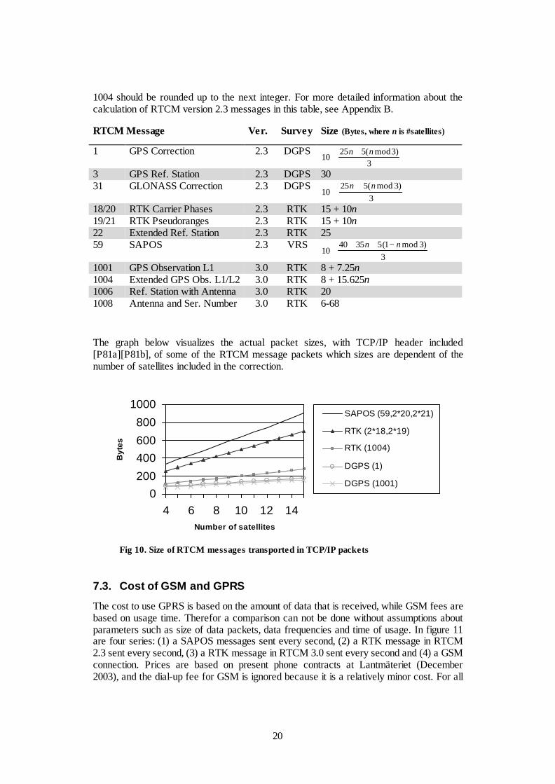
20
1004 should be rounded up to the next integer. For more detailed information about thecalculation of RTCM version 2.3 messages in this table, see Appendix B.
RTCM Message Ver. Survey Size (Bytes, where n is #satellites)
1 GPS Correction 2.3 DGPS3
)3mod(52510
nn ++
3 GPS Ref. Station 2.3 DGPS 3031 GLONASS Correction 2.3 DGPS
3)3mod(525
10nn ++
18/20 RTK Carrier Phases 2.3 RTK 15 + 10n19/21 RTK Pseudoranges 2.3 RTK 15 + 10n22 Extended Ref. Station 2.3 RTK 2559 SAPOS 2.3 VRS
3)3mod1(53540
10nn −+++
1001 GPS Observation L1 3.0 RTK 8 + 7.25n1004 Extended GPS Obs. L1/L2 3.0 RTK 8 + 15.625n1006 Ref. Station with Antenna 3.0 RTK 201008 Antenna and Ser. Number 3.0 RTK 6-68
The graph below visualizes the actual packet sizes, with TCP/IP header included[P81a][P81b], of some of the RTCM message packets which sizes are dependent of thenumber of satellites included in the correction.
Fig 10. Size of RTCM messages transported in TCP/IP packets
7.3. Cost of GSM and GPRS
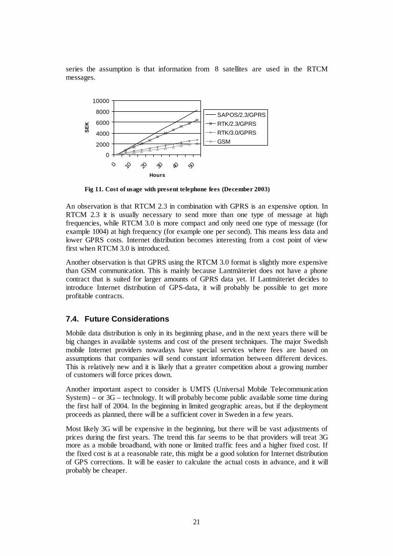
The cost to use GPRS is based on the amount of data that is received, while GSM fees arebased on usage time. Therefor a comparison can not be done without assumptions aboutparameters such as size of data packets, data frequencies and time of usage. In figure 11are four series: (1) a SAPOS messages sent every second, (2) a RTK message in RTCM2.3 sent every second, (3) a RTK message in RTCM 3.0 sent every second and (4) a GSMconnection. Prices are based on present phone contracts at Lantmäteriet (December2003), and the dial-up fee for GSM is ignored because it is a relatively minor cost. For all
0200400600800
1000
4 6 8 10 12 14Number of satellites
Byt
es
SAPOS (59,2*20,2*21)
RTK (2*18,2*19)
RTK (1004)
DGPS (1)
DGPS (1001)
21
series the assumption is that information from 8 satellites are used in the RTCMmessages.
Fig 11. Cost of usage with present telephone fees (December 2003)
An observation is that RTCM 2.3 in combination with GPRS is an expensive option. InRTCM 2.3 it is usually necessary to send more than one type of message at highfrequencies, while RTCM 3.0 is more compact and only need one type of message (forexample 1004) at high frequency (for example one per second). This means less data andlower GPRS costs. Internet distribution becomes interesting from a cost point of viewfirst when RTCM 3.0 is introduced.
Another observation is that GPRS using the RTCM 3.0 format is slightly more expensivethan GSM communication. This is mainly because Lantmäteriet does not have a phonecontract that is suited for larger amounts of GPRS data yet. If Lantmäteriet decides tointroduce Internet distribution of GPS-data, it will probably be possible to get moreprofitable contracts.
7.4. Future Considerations
Mobile data distribution is only in its beginning phase, and in the next years there will bebig changes in available systems and cost of the present techniques. The major Swedishmobile Internet providers nowadays have special services where fees are based onassumptions that companies will send constant information between different devices.This is relatively new and it is likely that a greater competition about a growing numberof customers will force prices down.
Another important aspect to consider is UMTS (Universal Mobile TelecommunicationSystem) – or 3G – technology. It will probably become public available some time duringthe first half of 2004. In the beginning in limited geographic areas, but if the deploymentproceeds as planned, there will be a sufficient cover in Sweden in a few years.
Most likely 3G will be expensive in the beginning, but there will be vast adjustments ofprices during the first years. The trend this far seems to be that providers will treat 3Gmore as a mobile broadband, with none or limited traffic fees and a higher fixed cost. Ifthe fixed cost is at a reasonable rate, this might be a good solution for Internet distributionof GPS corrections. It will be easier to calculate the actual costs in advance, and it willprobably be cheaper.
0
2000
4000
6000
8000
10000
0 10 20 30 40 50
Hours
SE
K
SAPOS/2.3/GPRSRTK/2.3/GPRSRTK/3.0/GPRSGSM

22
7.5. Conclusions
Mobile data communication is now at a break point. Today one can not motivate a changeto Internet distribution based on purely cost aspects, but in a few years it is likely thatmore competition and flat rates of fees will change this picture. It should be of interest tokeep updated in these areas.
Since frequencies are such an important factor when calculating the cost of GPRSdistribution, it might be interesting to investigate how often packets have to be sent tokeep and accurate positioning. Services where users could decide frequencies of differentRTCM-messages could be introduced. It’s technically possible to implement aNtripCaster containing information about this, which would lead to services that are moresuited for specific users. It would also lead to lower costs.
8. Communication Between NtripCastersSolutions where Ntrip is used only in parts of the communications can be interesting inthe future. One could for example think of systems where a NtripCaster – or some otherkind of central unit – is installed locally in an area. Data packets in Ntrip format arrives tothe NtripCaster, but is then distributed to the users by some other method ofcommunication. Lantmäteriet would then only distribute data to this NtripCaster, leavingfor the local provider to set-up arrangements for the final delivery in for example a radionet.
Another possible scenario is a system with several communicating NtripCasters, whereusers can access the one closest to them, but still be able to obtain data from otherNtripCasters as well. This does not have to be within the same organization. In somecountries, like Denmark, there exists a few independent GPS correction providers. Aservice where customers can access corrections from different providers would probablybe of interest.
These and similar tasks would need NtripCasters to be able to communicate with oneanother – alternatively that it only seems from the user’s point of view that they arecommunicating, while all the processing is done in a NtripClient. In the presentconfiguration of NtripCasters and NtripClients this is not possible. This section willpresent three suggestions of possible modifications of Ntrip components, for an evenmore flexible use of the Ntrip protocol. The key aspect is where implementation changeswould be required.
8.1. Modified NtripClient
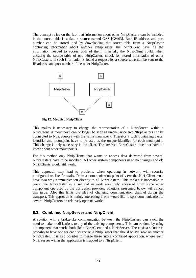
A simple solution to implement, if a user would like to access NtripSources located atdifferent NtripCasters, is to have all the extra processing in a modified NtripClient. Thisprocess is invisible for the user. A connection is made to one NtripClient, but theNtripClient merge the source-tables of all available NtripClients and presents a completelist for the user. Connections between the NtripClient and all NtripCasters are direct; theNtripCasters never communicates with one another.
23
The concept relies on the fact that information about other NtripCasters can be includedin the source-table in a data structure named CAS [GW03]. Both IP-address and portnumber can be stored, and by downloading the source-table from a NtripCastercontaining information about another NtripCaster, the NtripClient have all theinformation needed to access both of them. Internally the NtripClient could, whenupdating the source-table of one NtripCaster, check for stored information of otherNtripCasters. If such information is found a request for a source-table can be sent to theIP address and port number of the other NtripCaster.
Fig 12. Modified NtripClient
This makes it necessary to change the representation of a NtripSource within aNtripClient. A mountpoint can no longer be seen as unique, since two NtripCasters can beconnected to NtripSources with the same mountpoint. Therefor a tuple containing casteridentifier and mountpoint have to be used as the unique identifier for each mountpoint.This change is only necessary in the client. The involved NtripCasters does not have toknow about other mountpoints.
For this method only NtripClients that wants to access data delivered from severalNtripCasters have to be modified. All other system components need no changes and oldNtripClients would still work.
This approach may lead to problems when operating in network with securityconfigurations like firewalls. From a communication point of view the NtripClient musthave two-way communication directly to all NtripCasters. This makes it impossible toplace one NtripCaster in a secured network area only accessed from some othercomponent operated by the correction provider. Solutions presented below will cancelthis issue. Also this limits the idea of changing communication channel during thetransport. This approach is mainly interesting if one would like to split communication toseveral NtripCasters on relatively open networks.
8.2. Combined NtripServer and NtripClient
A solution with a bridge-like communication between the NtripCasters can avoid theneed to make modifications to any of the existing components. This can be done by usinga component that works both like a NtripClient and a NtripServer. The easiest solution isprobably to have one for each source on a NtripCaster that should be available on anotherNtripCaster. It is also possible to merge these into a combined application, where eachNtripServer within the application is mapped to a NtripClient.
24
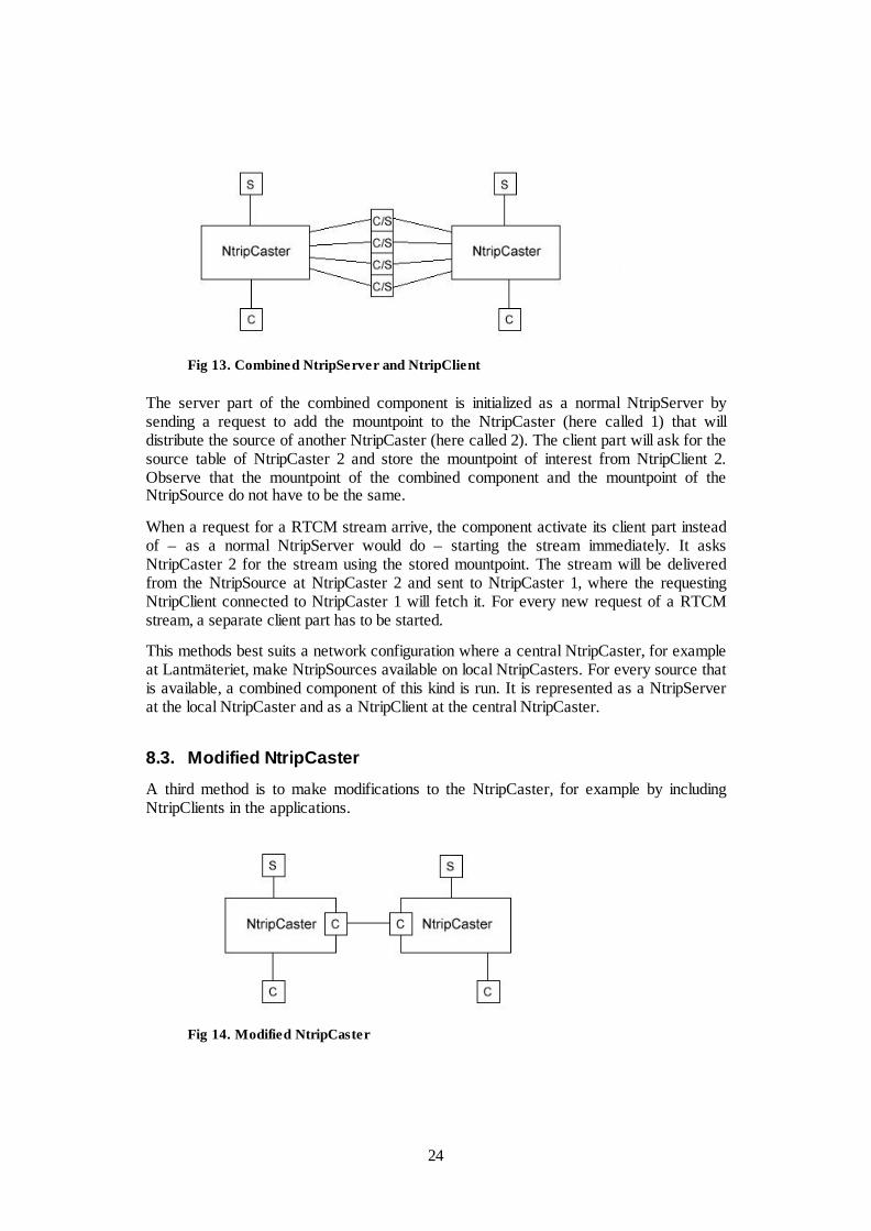
Fig 13. Combined NtripServer and NtripClient
The server part of the combined component is initialized as a normal NtripServer bysending a request to add the mountpoint to the NtripCaster (here called 1) that willdistribute the source of another NtripCaster (here called 2). The client part will ask for thesource table of NtripCaster 2 and store the mountpoint of interest from NtripClient 2.Observe that the mountpoint of the combined component and the mountpoint of theNtripSource do not have to be the same.
When a request for a RTCM stream arrive, the component activate its client part insteadof – as a normal NtripServer would do – starting the stream immediately. It asksNtripCaster 2 for the stream using the stored mountpoint. The stream will be deliveredfrom the NtripSource at NtripCaster 2 and sent to NtripCaster 1, where the requestingNtripClient connected to NtripCaster 1 will fetch it. For every new request of a RTCMstream, a separate client part has to be started.
This methods best suits a network configuration where a central NtripCaster, for exampleat Lantmäteriet, make NtripSources available on local NtripCasters. For every source thatis available, a combined component of this kind is run. It is represented as a NtripServerat the local NtripCaster and as a NtripClient at the central NtripCaster.
8.3. Modified NtripCaster
A third method is to make modifications to the NtripCaster, for example by includingNtripClients in the applications.
Fig 14. Modified NtripCaster

25
A request for a stream will trigger a built-in NtripCaster to act as a client at the otherNtripCaster. This would have the same security issues as the method in 8.2, where therequesting NtripClient must not have a direct connection to the NtripCaster that handlesthe source it asks for. The NtripClient does not need to know that the NtripSource is onanother NtripCaster either. Everything can be dealt with internally.
The modified NtripCaster have to keep track of which NtripSources that are directlyconnected and which NtripSources that have to be fetched from another NtripCaster. Thecommunication between the NtripCaster can be closely integrated, where they almostwork as one, or on a more independent basis, depending on the demands of the networkconfiguration that will be used.
9. Monitoring the Quality of CorrectionsWhen people call the SWEPOS control center with problems concerning RTCM datadistribution, a good tool for the support would be real-time connections to some rovers inthe network. The support staff could then see the problem from the user point of view, todetermine if there is a problem with the network or with the user’s receiver. It would alsogive constant feedback of the quality of present corrections; and it would be possible tolog information for later use, or for statistical calculations.
As an example and evaluation of topics in this paper, the problem was solved with datadistribution over a computer network with two communicating components: (1) a loggingunit at the position of the rover obtaining data from a GPS-receiver, and (2) a monitoringunit at the control center. The result is an implementation of GPS-data distribution overan intranet.
9.1. Correction Quality Parameters
The true position of the rover is known, hence it is possible to calculate the differencebetween the true position and the position values that are received from a GPS-receiverusing the corrections distributed in the network. For the positioning error the interestingvalues are (1) difference in latitude, (2) difference in longitude and (3) difference inaltitude. The three formulas are:
rlatlat
dLat ⋅−= π180
0
)cos(180
0 latrlonlon
dLon ⋅⋅−= π
NaltaltdAlt +−= 0
where r is the radius of earth and N is the geoidal separation.
Number of satellites used in the solution, HDOP (Horizontal Dilution Of Precision) andthe age of the correction are other values of interest that are received and displayed by themonitoring unit.
26
Another interesting quality value is the time it takes for the solution to get fixed. Thismeans – simplified – that the ranges from receiver to satellite consist of a fixed integerpart and a moving fractional part. In some sense one can say that the calculations havereached an optimal solution then. The process for the solution to get fixed begins everytime a new position is to be determined by a rover. This is simulated in the monitorsystem with a system reset, clearing all known data.
9.2. Components and Communication
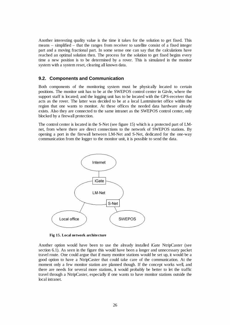
Both components of the monitoring system must be physically located to certainpositions. The monitor unit has to be at the SWEPOS control center in Gävle, where thesupport staff is located; and the logging unit has to be located with the GPS-receiver thatacts as the rover. The latter was decided to be at a local Lantmäteriet office within theregion that one wants to monitor. At these offices the needed data hardware alreadyexists. Also they are connected to the same intranet as the SWEPOS control center, onlyblocked by a firewall protection.
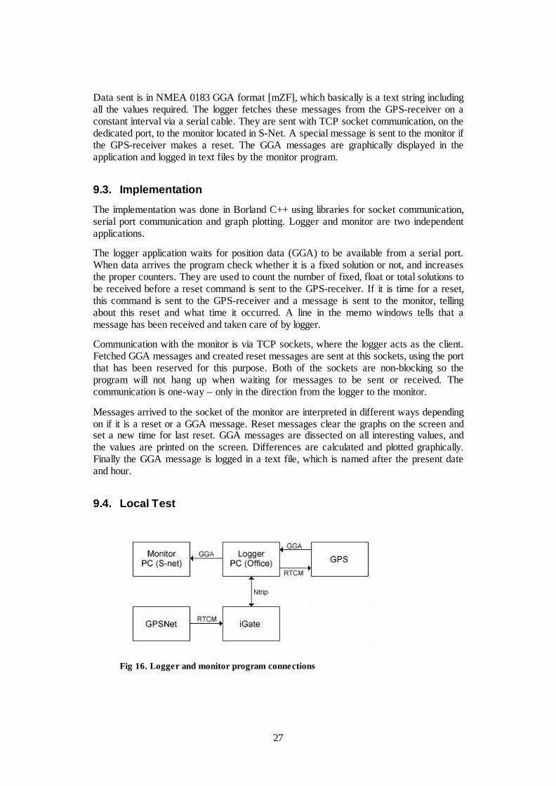
The control center is located in the S-Net (see figure 15) which is a protected part of LM-net, from where there are direct connections to the network of SWEPOS stations. Byopening a port in the firewall between LM-Net and S-Net, dedicated for the one-waycommunication from the logger to the monitor unit, it is possible to send the data.
Fig 15. Local network architecture
Another option would have been to use the already installed iGate NtripCaster (seesection 6.1). As seen in the figure this would have been a longer and unnecessary packettravel route. One could argue that if many monitor stations would be set up, it would be agood option to have a NtripCaster that could take care of the communication. At themoment only a few monitor station are planned though. If the concept works well, andthere are needs for several more stations, it would probably be better to let the traffictravel through a NtripCaster, especially if one wants to have monitor stations outside thelocal intranet.
27
Data sent is in NMEA 0183 GGA format [mZF], which basically is a text string includingall the values required. The logger fetches these messages from the GPS-receiver on aconstant interval via a serial cable. They are sent with TCP socket communication, on thededicated port, to the monitor located in S-Net. A special message is sent to the monitor ifthe GPS-receiver makes a reset. The GGA messages are graphically displayed in theapplication and logged in text files by the monitor program.
9.3. Implementation
The implementation was done in Borland C++ using libraries for socket communication,serial port communication and graph plotting. Logger and monitor are two independentapplications.
The logger application waits for position data (GGA) to be available from a serial port.When data arrives the program check whether it is a fixed solution or not, and increasesthe proper counters. They are used to count the number of fixed, float or total solutions tobe received before a reset command is sent to the GPS-receiver. If it is time for a reset,this command is sent to the GPS-receiver and a message is sent to the monitor, tellingabout this reset and what time it occurred. A line in the memo windows tells that amessage has been received and taken care of by logger.
Communication with the monitor is via TCP sockets, where the logger acts as the client.Fetched GGA messages and created reset messages are sent at this sockets, using the portthat has been reserved for this purpose. Both of the sockets are non-blocking so theprogram will not hang up when waiting for messages to be sent or received. Thecommunication is one-way – only in the direction from the logger to the monitor.
Messages arrived to the socket of the monitor are interpreted in different ways dependingon if it is a reset or a GGA message. Reset messages clear the graphs on the screen andset a new time for last reset. GGA messages are dissected on all interesting values, andthe values are printed on the screen. Differences are calculated and plotted graphically.Finally the GGA message is logged in a text file, which is named after the present dateand hour.
9.4. Local Test
Fig 16. Logger and monitor program connections
28
The applications were tested on a computer in the SWEPOS control center. Naturally thesocket communication between monitor and logger worked without problems – because itonly loop back to the same computer –, but there should be no problems separating thecomponents. The socket communication between the two applications was tested inLM-net. Communication between LM-Net and S-Net (see figure 15) should only be amatter of opening one port in the firewall. Figure 16 describes how the system will work.The only difference in this testing is the position of monitor.
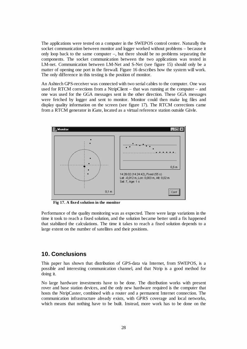
An Ashtech GPS-receiver was connected with two serial cables to the computer. One wasused for RTCM corrections from a NtripClient – that was running at the computer – andone was used for the GGA messages sent in the other direction. These GGA messageswere fetched by logger and sent to monitor. Monitor could then make log files anddisplay quality information on the screen (see figure 17). The RTCM corrections camefrom a RTCM generator in iGate, located as a virtual reference station outside Gävle.
Fig 17. A fixed solution in the monitor
Performance of the quality monitoring was as expected. There were large variations in thetime it took to reach a fixed solution, and the solution became better until a fix happenedthat stabilized the calculations. The time it takes to reach a fixed solution depends to alarge extent on the number of satellites and their positions.
10. ConclusionsThis paper has shown that distribution of GPS-data via Internet, from SWEPOS, is apossible and interesting communication channel, and that Ntrip is a good method fordoing it.
No large hardware investments have to be done. The distribution works with presentrover and base station devices, and the only new hardware required is the computer thathosts the NtripCaster, combined with a router and a permanent Internet connection. Thecommunication infrastructure already exists, with GPRS coverage and local networks,which means that nothing have to be built. Instead, more work has to be done on the
29
software side. One has to make sure that rover software can receive corrections viaInternet and that the system at the control center is configured properly – includingfeatures as authentication and fee methods. It is possible to either install a completely newsystem with a stand alone NtripCaster, or use a more integrated approach with the alreadyexisting components in GPSNet.
Internet distribution works in both VRS and broadcast mode. New specifications of dataformats will adapt better to the characteristics of packet transfer via Internet, while the oldformats still work, although they are a bit more cumbersome to use. Broadcasting is aninteresting subject for future implementations and a protocol like SAPOS might beuseful. A more thorough investigation of broadcast methods should not be performeduntil the new RTCM broadcast messages are defined by SC-104.
The NtripCaster should be installed locally at Lantmäteriet in Gävle – mostly because ofmaintenance and integration reasons. Also this will reduce the problem of data packetswith long latencies and give more stable connections. The feed of data from referencestations can be handled with Ntrip, but as a first step the best solution would be tomaintain the present structure of leased lines, where RTCM streams are fetched from thesame sockets as today. Hence the NtripServers will run at the control center and Internetdistribution can work together with present systems, making a secure and gradual changeto the new system possible.
Several methods for a more flexible use, with more than one NtripCaster, have beensuggested. Since Ntrip is an open system, the possibilities are extensive and lies more inthe needed workload of implementation than in technical limitations. One should notimplement solutions where too many local control centers are needed and the natural non-geographic nature of Internet is ignored. As few steps as possible between user andRTCM source is generally the best approach.
Today a change to Internet distribution would not lead to major cost effects. Just in a fewyears this picture will probably be completely different, though. New technologies andbetter availability of mobile Internet will give lower traffic fees. Also the coming newRTCM 3.0 format, with smaller messages, will reduce costs significantly because thecommon pay method for mobile Internet traffic is based on the amount of data sent. Thisalso gives the possibility to let user pay only for the type of messages and the frequenciesthat they need; that means better adapted agreements with different customers. The one-time cost to introduce Internet distribution is low.
The test system that was set-up, and the monitor system that was implemented, showsthat the performance of Ntrip is as expected. Latencies is not a problem, although morerealistic field test would be necessary before it can be claimed for sure. Software andhardware that exists today works with Ntrip, but since it is relatively new functions itsometimes can be rather cumbersome to install; usually the newest software version isrequired. This is natural with new technologies and will probably be much improved inthe future, since companies involved in accurate GPS positioning shows great interests inongoing projects. An introduction of Internet distribution of GPS-data at Lantmäterietwould probably be successful.
30
11. ReferencesArticles and books
[CDK02] Castro M., Druschel P., Kerrmarrec A.-M., Rowstron A., “Scribe: A large-scale and decentralized application-level multicast infrastructure” (2002),IEEE Journal on Selected Areas in Communications, Vol. 20, No. 8
[CTV03] Chen R., Toran-Marti F., Ventura-Traveset J. (2003), “Access to the EGNOSsignal in space over mobile-IP”, GPS Solutions, Vol. 7, No. 1
[E83] Ekman M. (1983), Sfärisk trigonometri och jordellipsoidens geometri,Lantmäteriet, Gävle
[E98] Estrin D. et al. (1998), “Protocol Independent Multicast-Sparse Mode (PIM-SM): Protocol Specification “, The Internet Engineering Task Force, RFC2362
[EZT02] Euler H.-J., Zebhauser B., Townsend B., Wübbena G. (2002), “Comparisonof Different Proposals for Reference Station Network InformationDistribution Formats”, Proceeding of ION GPS 2002
[F97] Fielding R. et al. (1997), “Hypertext Transfer Protocol – HTTP/1.1 “, TheInternet Engineering Task Force, RFC 2068
[GW03] Gebhard H., Weber G. (2003), ”Ntrip, Version 1.0”, Federal Agency forCartography and Geodesy, Germany
[HBH03] Hjálmtýsson G., Brynjúlfsson B., Helgason O. (2003), “Self-configuringLightweight Internet Multicast”, Department of Computer Science,Reykjavík University
[HLC94] Hofmann-Wellenhof B., Lichtenegger H., Colins J. (1994), GPS, Theory andPractice, Springer-Verlag, Wien
[JHW03] Jonsson B., Hedling G., Wiklund P. (2003), “SWEPOS™ Network-RTKServices – status, applications and experiences”, National Land Survey ofSweden
[LVC02] Landau H., Vollath U., Chen X. (2002), “Virtual Reference Station Systems”,Journal of Global Positioning Systems, Vol. 1, No. 2
[LVC03] Landau H., Vollath U., Chen X. (2003), “Virtual Reference Station versusBroadcast Solutions in Network RTK – Advantages and Limitations”,Trimble Terrasat GmbH
[P81a] Postel J. ed. (1981),”Internet Protocol”, The Internet Engineering Task Force,RFC 791
[P81b] Postel J. ed. (1981), “Transmission Control Protocol”, The InternetEngineering Task Force, RFC 793
[R01] RTCM Special Committee No. 104 (2001), “RTCM RecommendedStandards for Differential GNSS (Global Navigation Satellite Systems)Service, Version 2.3”, Radio Technical Commission for Maritime Services

31
[R03] RTCM Special Committee No. 104 (2003), “Committee Draft for Vote.RTCM Recommended Standards for Differential GNSS (Global NavigationSatellite Systems) Service, Version 3.0”, Radio Technical Commission forMaritime Services
[S96] Van Sickle J. (1996), GPS for Land Surveyors, Ann Arbor Press, USA
[TLA02] Talbot N., Lu G., Allison T., Vollath U. (2002), “Broadcast Network RTK –Transmission Standards and Results”, Proceeding of ION GPS 2002
[WB02] Wübbena G., Bagge A. (2002), “RTCM Message Type 59 – FKP fortransmission of FKP, version 1.0”, Geo++
User Manuals
[mGN] “GPSNet VRS Software User Guide, Version 2.10”, Trimble Geomatics andEngineering Division (2003)
[mGR] “GRIL Manual, Version 2.3”, Javad Navigation Systems (2003)
[mGS] “GPServer Data Publication Using the Internet User Guide, Version 2.10”,Trimble Geomatics and Engineering Division (2003)
[mIM] “Operation Manual for IMoS, LMV edition, revision 1.1”, Lantmäteriet(1998)
[mPV] “PCView User's Manual, Version 2.1.10 MS”, Javad Navigation Systems(2002)
[mSC] “Trimble Survey Controller Help, Version 10.7”, Trimble (2003)
[mUR] “UDP Relay, Version 0.9.1”, Geodetic Survey Division, Natural ResourcesCanada (2003)
[mZF] “Z-Family GPS Receivers, Technical Reference Manual”, Ashtech, ThalesNavigation (2002)
Web Pages
[wBKG] BKG Ntrip, igs.ifag.de/index_ntrip.htm
[wIETF] IETF RFC, www.ietf.org/rfc.html
[wIGS] IGS, igscb.jpl.nasa.gov
[wJAV] Javad Navigation Systems, www.javadgps.com
[wSPS] SAPOS, www.adv-online.de/produkte/sapos.htm
[wSWEP] SWEPOS, www.swepos.com
[wTRIM] Trimble, www.trimble.com
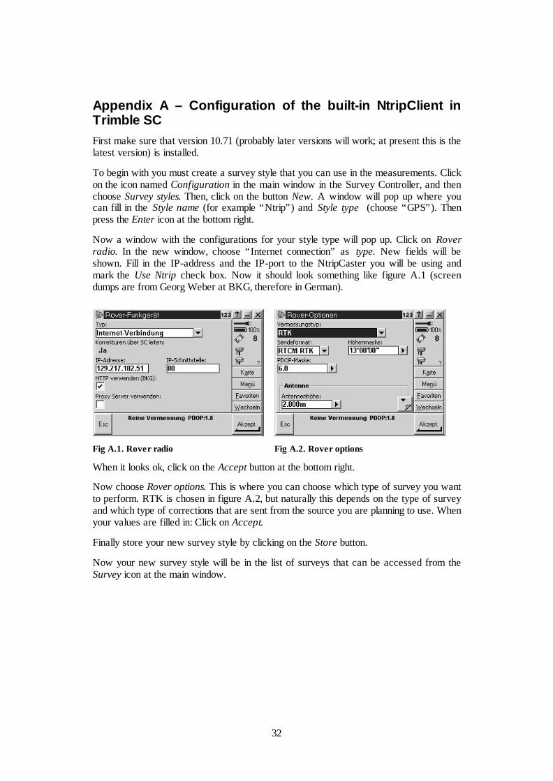
32
Appendix A – Configuration of the built-in NtripClient inTrimble SCFirst make sure that version 10.71 (probably later versions will work; at present this is thelatest version) is installed.
To begin with you must create a survey style that you can use in the measurements. Clickon the icon named Configuration in the main window in the Survey Controller, and thenchoose Survey styles. Then, click on the button New. A window will pop up where youcan fill in the Style name (for example “Ntrip”) and Style type (choose “GPS”). Thenpress the Enter icon at the bottom right.
Now a window with the configurations for your style type will pop up. Click on Roverradio. In the new window, choose “Internet connection” as type. New fields will beshown. Fill in the IP-address and the IP-port to the NtripCaster you will be using andmark the Use Ntrip check box. Now it should look something like figure A.1 (screendumps are from Georg Weber at BKG, therefore in German).
Fig A.1. Rover radio Fig A.2. Rover options
When it looks ok, click on the Accept button at the bottom right.
Now choose Rover options. This is where you can choose which type of survey you wantto perform. RTK is chosen in figure A.2, but naturally this depends on the type of surveyand which type of corrections that are sent from the source you are planning to use. Whenyour values are filled in: Click on Accept.
Finally store your new survey style by clicking on the Store button.
Now your new survey style will be in the list of surveys that can be accessed from theSurvey icon at the main window.
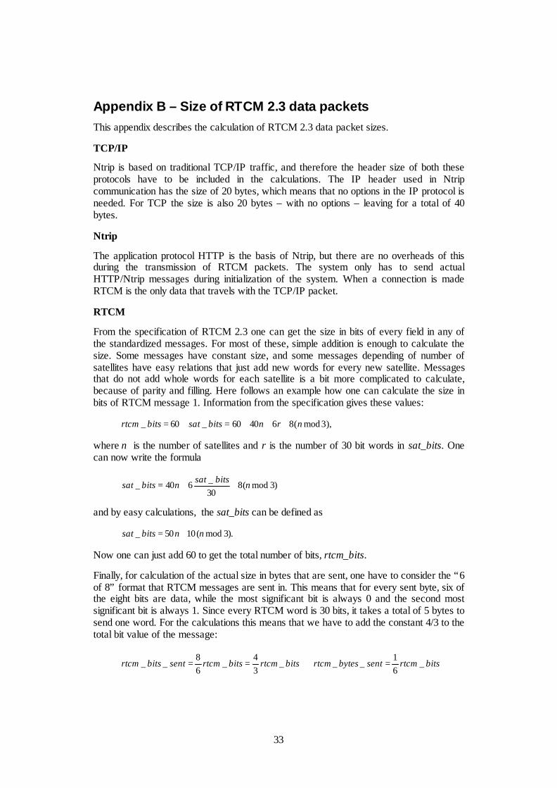
33
Appendix B – Size of RTCM 2.3 data packetsThis appendix describes the calculation of RTCM 2.3 data packet sizes.
TCP/IP
Ntrip is based on traditional TCP/IP traffic, and therefore the header size of both theseprotocols have to be included in the calculations. The IP header used in Ntripcommunication has the size of 20 bytes, which means that no options in the IP protocol isneeded. For TCP the size is also 20 bytes – with no options – leaving for a total of 40bytes.
Ntrip
The application protocol HTTP is the basis of Ntrip, but there are no overheads of thisduring the transmission of RTCM packets. The system only has to send actualHTTP/Ntrip messages during initialization of the system. When a connection is madeRTCM is the only data that travels with the TCP/IP packet.
RTCM
From the specification of RTCM 2.3 one can get the size in bits of every field in any ofthe standardized messages. For most of these, simple addition is enough to calculate thesize. Some messages have constant size, and some messages depending of number ofsatellites have easy relations that just add new words for every new satellite. Messagesthat do not add whole words for each satellite is a bit more complicated to calculate,because of parity and filling. Here follows an example how one can calculate the size inbits of RTCM message 1. Information from the specification gives these values:
),3mod(864060_60_ nrnbitssatbitsrtcm +++=+=
where n is the number of satellites and r is the number of 30 bit words in sat_bits. Onecan now write the formula
)3mod(830_640_ nbitssatnbitssat ++=
and by easy calculations, the sat_bits can be defined as
).3mod(1050_ nnbitssat +=
Now one can just add 60 to get the total number of bits, rtcm_bits.
Finally, for calculation of the actual size in bytes that are sent, one have to consider the “6of 8” format that RTCM messages are sent in. This means that for every sent byte, six ofthe eight bits are data, while the most significant bit is always 0 and the second mostsignificant bit is always 1. Since every RTCM word is 30 bits, it takes a total of 5 bytes tosend one word. For the calculations this means that we have to add the constant 4/3 to thetotal bit value of the message:
=== bitsrtcmsentbytesrtcmbitsrtcmbitsrtcmsentbitsrtcm _
61
___34
_68
__

34
Total
For total size of message, just add together TCP/IP size and RTCM size:
sentbytesrtcmbytestcpipsentbytestotal _____ +=
Verification
To verify that these theoretical values are correct, the RTCM data traffic received to aNtripClient was monitored. It showed to be correct for all messages.
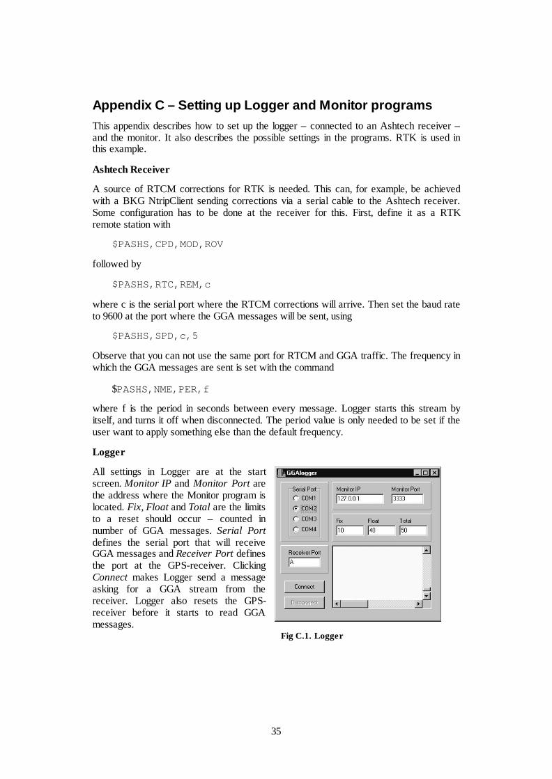
35
Appendix C – Setting up Logger and Monitor programsThis appendix describes how to set up the logger – connected to an Ashtech receiver –and the monitor. It also describes the possible settings in the programs. RTK is used inthis example.
Ashtech Receiver
A source of RTCM corrections for RTK is needed. This can, for example, be achievedwith a BKG NtripClient sending corrections via a serial cable to the Ashtech receiver.Some configuration has to be done at the receiver for this. First, define it as a RTKremote station with
$PASHS,CPD,MOD,ROV
followed by
$PASHS,RTC,REM,c
where c is the serial port where the RTCM corrections will arrive. Then set the baud rateto 9600 at the port where the GGA messages will be sent, using
$PASHS,SPD,c,5
Observe that you can not use the same port for RTCM and GGA traffic. The frequency inwhich the GGA messages are sent is set with the command
$PASHS,NME,PER,f
where f is the period in seconds between every message. Logger starts this stream byitself, and turns it off when disconnected. The period value is only needed to be set if theuser want to apply something else than the default frequency.
Logger
All settings in Logger are at the startscreen. Monitor IP and Monitor Port arethe address where the Monitor program islocated. Fix, Float and Total are the limitsto a reset should occur – counted innumber of GGA messages. Serial Portdefines the serial port that will receiveGGA messages and Receiver Port definesthe port at the GPS-receiver. ClickingConnect makes Logger send a messageasking for a GGA stream from thereceiver. Logger also resets the GPS-receiver before it starts to read GGAmessages.
Fig C.1. Logger
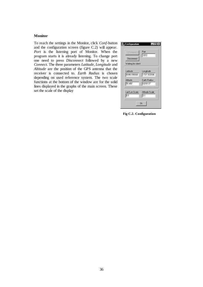
36
Monitor
To reach the settings in the Monitor, click Conf-buttonand the configuration screen (figure C.2) will appear.Port is the listening port of Monitor. When theprogram starts it is already listening. To change portone need to press Disconnect followed by a newConnect. The three parameters Latitude, Longitude andAltitude are the position of the GPS antenna that thereceiver is connected to. Earth Radius is chosendepending on used reference system. The two scalefunctions at the bottom of the window are for the solidlines displayed in the graphs of the main screen. Theseset the scale of the display
Fig C.2. Configuration
1999:2 Andreasson Thor-Björn, Engman Linda: Multipath at the SWEPOS stationsEvaluation of eccosorb, a microwave absorbing material
1999:3 Lilje Mikael: Geodesy and Surveying in the future
1999:4 Jonsson, Bo: Civil Service Interface Committee International InformationSubcommittee 7 th European Meeting
1999:12 Jonsson. Bo: Proceedeings of the 13th general meeting of the nordic geodeticcommission.
2000:2 Engfeldt Andreas, Jivall Lotti: Kort introduktion till GNSS
2000:3 Christina Kempe: Metodstudie för inmätning av skogsbilvägar.
2000:4 Niklas Svanholm: Jämförelse av olika metoder att föra över kartdetaljer till ettnytt koordinatsystem.
2000:5 RefStrat – Strategier för referenssystem och referensnät.
2001:1 Engberg, Lars: Geodesi 2000 - svensk geodesiverksamhet under kommandetioårsperiod.
2001:6 Jivall, Lotti: SWEREF 99 – New ETRS 89 Coordinates in Sweden, AnalysisReport.
2001:7 Jivall, Lidberg, Lilje, Reit: Transformationssamband mellan SWEREF 99 ochRT90/RH 70.
2001:10 Rönnberg Andreas: Undersökning av tjänster för differentiell GPS.
2002:1 Wiklund Peter (sammanställt rapporten): Slutrapport för projekt PositionStockholm-Mälaren 1.
2002:2 Wahlund Sara: Production measurements with Network RTK tests andanalysis.
2002:5 Alfredsson Anders: Studier av deformationer vid byte av koordinatsystem.
2002:7 Persson Jan, Brynte Stefan: Kompabilitet för Nätverks-RTK-programvaranTrimble GPSNet med olika typer av rörliga mottagare.
2003: 4 Engfeldt Andreas, Norin Dan: The 2002 NKG GNSMART/ GPSNet TestCampaign.
2003:10 Engfeldt Andreas, Jivall Lotti: Så fungerar GNSS.

L A N T M Ä T E R I E T
Blankettfö r r å det 801 82 GÄ V LE Tfn 026 - 63 30 00 Fax 026 - 68 75 94Internet: w w w .l antm a ter iet.se