document pn: date: august 2019 daikin classroom ceiling unit … · ceiling models ahf, ahb, ahv,...
TRANSCRIPT
Installation and Maintenance Manual IM 830-7Group: Unit VentilatorDocument PN: 910284701Date: August 2019
Daikin Classroom Ceiling Unit Ventilators Ceiling Models AHF, AHB, AHV, and AHR Digital Ready, MicroTech® (“J” Vintage) Field Control by Others
Ventilation rate certified and tested per Air Conditioning, Heating and Refrigeration Institute (AHRI) Standard 840.
Before beginning installation, please read this publication in its entirety.Develop a thorough understanding before starting the installation procedure.
This manual is to be used as a guide. Each installation is unique, so only general topics are covered. The order in which topics are covered may not be those required for the actual installation.
IMPORTANT!

Contents
Nomenclature.......................................................................3Models AHF, AHB, AHV and AHR .....................................4Safety Information.............................................................4Inspection and Storage .....................................................5
Pre-Installation Considerations .........................................6VentiMatic™ Shutter Assembly ................................................... 7Typical Discharge Air Arrangements .................................7
36" Deep Unit (750 to 1500 CFM) ....................................740" Deep Unit (750 to 2000 CFM) ....................................740" Deep Unit (750 to 2000 CFM) ....................................8
Intake Air Arrangements .....................................................9Intake Air Knockouts .........................................................9Vertical Outdoor Air (Top) Intake Duct Collar Installation 10Horizontal Outdoor Air (Upper) Intake Duct Collar Installation.......................................................................10Horizontal Room Air (Lower) Intake Duct Collar Installation.......................................................................11Horizontal Room Air (Lower) Intake and Horizontal Outdoor Air (Upper) Intake Duct Collars Installation.....................11
Duct System Considerations............................................12Installing Louvers ..............................................................14
Typical Installation Methods............................................15
Installing the VentiMatic Shutter Assembly ....................16Unit Ventilator Installation ................................................18
Tools Required ................................................................18Lifting The Unit Into Position ...........................................19Anchoring The Ceiling Unit Ventilator .............................20Making Piping Connections ............................................21Coil Connection Locations ..............................................23
Typical Valve Packages .....................................................28Steam Modulating Valve Selection .................................34Typical Piping Arrangements ..........................................35
Split Systems Guidelines..................................................41Making Control Connections ............................................44
MicroTech® Unit Mounted Direct Digital Control (DDC) Components – Models AHF, AHV, and AHR ..................44
MicroTech Unit Electrical Connections ...........................49Digital Ready™ – Face & Bypass Control Components Model AHF .....................................................................53Digital Ready™ Wiring Diagram .....................................54Digital Ready – Unit Mounted .........................................55Temperature Sensor Specifications ................................55Digital Ready – Damper Actuator Specifications ............55Digital Ready Unit Electrical Connections ......................56Controls by Others Components ....................................57Typical Controls by Others Wiring Diagram – Units with EC Motor Variable Airflow .....................................................60Typical Controls by Others Wiring Diagram - 3-Speed EC Motor ...............................................................................61Controls by Others – Electrical Connections ..................62
Unit Ventilator(s) Start-up .................................................65Battery Backup ...............................................................65Start-up Procedure .........................................................65Install Unit Ventilator End Panels....................................67Complete Check, Test and Start Procedure ..................67Installer/Owner’s Responsibility ......................................67
IM 830-7 2 www.DaikinApplied.com

www.DaikinApplied.com 3 IM 830-7
Model Nomenclature U AHF 9 H10 A S 65 A B1 AT 26 G Y B 1
1 2 3 4 5 6 7 8 9 10 11 12 13 14 15
Category Code Item Code Option Code Designation & Description
Product Category 1 1 U Unit Ventilators
Model Type 2 2-4AHB Ceiling- Face & Bypass w/ Reheat AHR Ceiling- Valve Control w/ Reheat
AHF Ceiling- Face & Bypass AHV Ceiling- Valve Control
Design Series 3 5 9 Design J
Nominal Capacity 4 6-8
H07 High Static 750 CFM V07 EC Motor, Variable Airflow 750 CFM
H10 High Static 1000 CFM V10 EC Motor, Variable Airflow1000 CFM
H13 High Static 1250 CFM V13 EC Motor, Variable Airflow 1250 CFM
H15 High Static 1500 CFM V15 EC Motor, Variable Airflow 1500 CFM
H20 High Static 2000 CFM V20 EC Motor, Variable Airflow 2000 CFM
Voltage 5 9
A 115/60/1 D 208/60/3
C 208/60/1 H 230/60/3
G 230/60/1 K 460/60/3
J 265-277/60/1
Coil Options
6 10 U [1] 2 Row CW/HW 2 pipe V [5] 2 Row CW
Numerical codes [#] include optional stainless steel drain pan.
D [2] 3 Row CW/HW 2 pipe S [6] 3 Row CW
E [3] 4 Row CW/HW 2 pipe W [7] 4 Row CW
F [4] 5 Row CW/HW 2 pipe Y [8] 5 Row CW
G [9] DX Z None
M [0] DX for HP Operation
Heating Options 7 11-12
12 3 Element Low Cap. Electric Heat 67 3 Row HW
13 6 Element Low Cap. Electric Heat 68 Steam Low Cap.
65 1 Row HW 69 Steam High Cap.
66 2 Row HW 00 None
Hand Orientation 8 13
A Same Hand LH E LH Heating/RH Cooling
B Same Hand RH F RH Heating/LH Cooling
D RH Electric Heat Only R Single Coil Left Hand
G RH Electric Heat / LH Cool S Single Coil Right Hand
Controls 9 14-15
## MicroTech Controls (see control code table below)
Control Features Feature Selections
Open Protocol
BACnet / Stand-Alone
LonMark
DCV CO2 Sensor
Factory-Installed Keypad LUI
Control Code
Economizer Control
Basic B1 B5 B9 BD BH BL BP BT
Expanded E1 E5 E9 ED EH EL EP ET
Leading-Edge L1 L5 L9 LD LH LL LP LT
23 Field Mounted Controls (By Others)
17 Digital Ready
Discharge 10 16-17
AH Front Discharge Duct Collar- 36" Length Unit
AT Front Disch. Double Deflection Grille- 36" Length
BD Down Disch. Double Deflection Grille- 40" Length
FD Front Discharge Duct Collar- 40" Length Unit
FG Front Disch. Double Deflection Grille- 40" Length
nomenClature

IM 830-7 4 www.DaikinApplied.com
Models AHF, AHB, AHV and AHRFigure 1: Data Plate Location
V
Unit Data Plate
Before beginning installation, please read this publication in its entirety.
Directions given in this bulletin for right and left sides assume a position facing the indoor side of the unit ventilator
INFORMATION
IMPORTANT
Before beginning installation, if provided, remove the protective plastic film covering the unit painted panels. Plastic packaging is a suffocation hazard, dispose of properly. Keep away from children.
NOTICE
Safety InformationFollow all safety codes. Wear safety glasses and work gloves. Use a quenching cloth for brazing operations. Have a fire extinguisher available. Follow all warnings and cautions in these instructions and attached to the unit. Consult applicable local building codes and National Electrical Codes (NEC) for special requirements.
Recognize safety information. When you see a safety symbol on the unit or in these instructions, be alert to the potential for personal injury. Understand the meanings of the words DANGER, WARNING, and CAUTION. DANGER identifies the most serious hazards that will result in death or severe personal injury; WARNING means the hazards can result in death or severe personal injury; CAUTION identifies unsafe practices that can result in personal injury or product and property damage.Improper installation, adjustment, service, maintenance, or use can cause explosion, fire, electrical shock, or other conditions which may result in personal injury or property damage. This product must be installed only by personnel with the training, experience, skills, and applicable licensing that makes him/her “a qualified professional HVACR installer.”
Disconnect all electrical power before servicing unit to prevent injury or death due to electrical shock.
Hazardous Voltage!Disconnect all electric power including remote disconnects before servicing. Failure to disconnect power before servicing can cause severe personal injury or death.
WARNING!
DANGER!
Use copper conductors only. Unit terminals are not designed to accept other types of conductors. Failure to do so may cause damage to the equipment.
CAUTION!
safety InformatIon
Model Nomenclature (Continued)Category Code Item Code Option Code Designation & Description
Return Air/Outside Air 11 18-19
25 Recirculation RA Bottom Grille- No RA/OA Dampers
26 RA Bottom Grille & OA Top Duct Collar
27 RA Bottom Grille & OA Rear Duct Collar
28 RA Rear Duct Grille & OA Top Duct Collar
29 RA Rear Duct Grille & OA Rear Duct Collar
Power Connection 12 20
G Box With Switch
J Box w/switch, w/USB
K Box w/switch, w/SD
M Box w/switch, w/USB, w/SD
Color 13 21 Y Off White
SKU Type 14 22 B Standard Delivery
Product Style 15 23 1 1st Style Change
www.DaikinApplied.com 5 IM 830-7
Before Installing Ceiling Unit VentilatorSafety and Warning Information
Personal injury hazard. Wear protective gloves to avoid possible cuts and abrasions from exposed edges. Avoid contact with sharp edges.
Make sure the lifting equipment can handle the weight of the unit safely. Personal injury may result if improper lifting and moving methods are used. (See Table 6 on page 19 for shipping weights)
This product was carefully packed and thoroughly inspected before leaving the factory. Responsibility for its safe delivery was assumed by the carrier upon acceptance of the shipment. Claims for loss or damage sustained in transit must therefore be made upon the carrier, as follows:VISIBLE LOSS OR DAMAGEAny external evidence of loss or damage must be noted on the freight bill or carrier’s receipt, and signed by the carrier’s agent. Failure to adequately describe such external evidence of loss or damage may result in the carrier’s refusing to honor a damage claim. The form required to file such a claim will be supplied by the carrier.CONCEALED LOSS OR DAMAGEConcealed loss or damage means loss or damage which does not become apparent until the product has been unpacked. The contents may be damaged in transit due to rough handling even though the carton may not show external damages. When the damage is discovered upon unpacking, make a written request for inspection by the carrier’s agent within fifteen (15) days of the delivery date. File a claim with the carrier since such damage is the carrier’s responsibility.
WARNING!
CAUTION!
IMPORTANT
Improper handling can damage internal components. Do not stand the unit on end or stack.
CAUTION!
Plastic packaging is a suffocation hazard, dispose of properly. Keep away from children.
WARNING!
Cleaning agents may cause serious damage to internal components, such as aluminum coils and electronic controls, etc. Do not operate unit ventilator while building maintenance cleaning agents are in use.
WARNING!
Inspection and StorageStorage – If equipment is stored for any length of time before installation, it should remain in its shipping packaging in a clean, dry, climate controlled area.
safety InformatIon
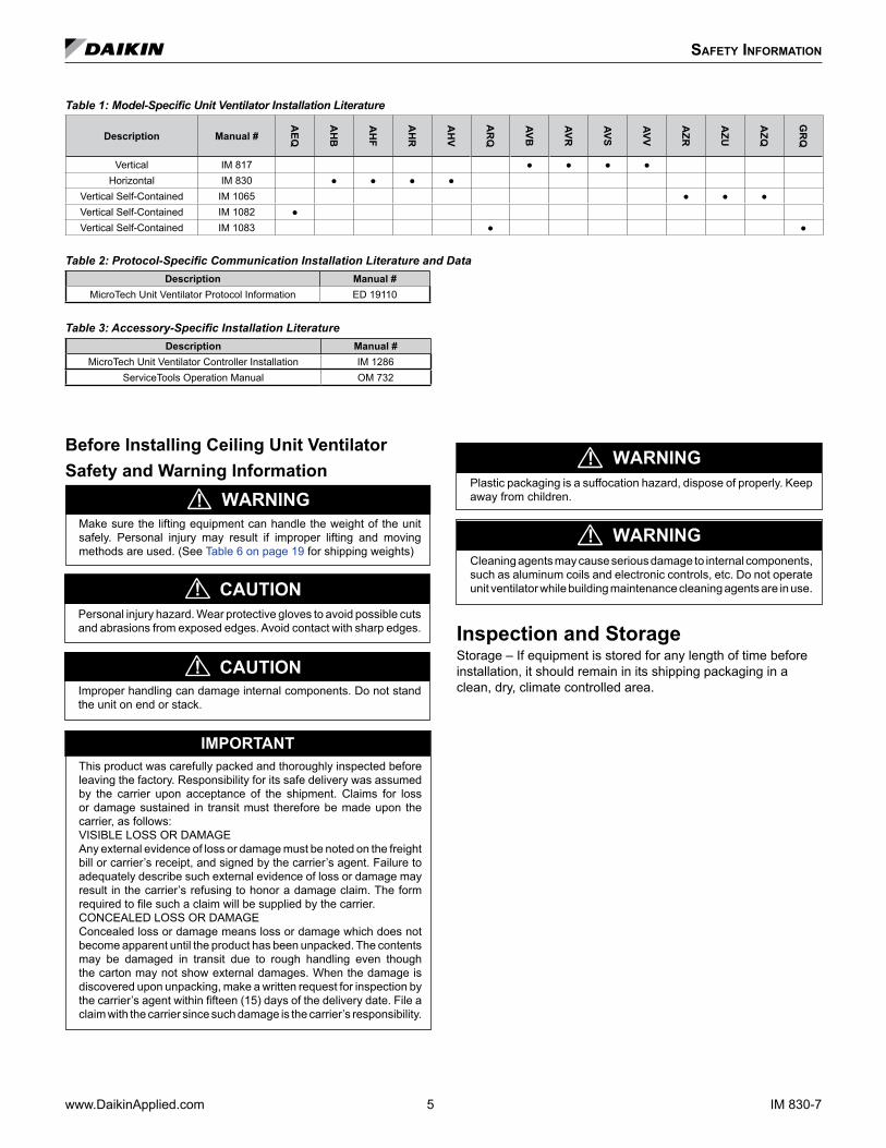
Table 1: Model-Specific Unit Ventilator Installation Literature
Description Manual #
AEQ
AH
B
AH
F
AH
R
AH
V
AR
Q
AVB
AVR
AVS
AVV
AZR
AZU
AZQ
GR
Q
Vertical IM 817 Horizontal IM 830
Vertical Self-Contained IM 1065 Vertical Self-Contained IM 1082 Vertical Self-Contained IM 1083
Table 2: Protocol-Specific Communication Installation Literature and Data Description Manual #
MicroTech Unit Ventilator Protocol Information ED 19110
Table 3: Accessory-Specific Installation Literature Description Manual #
MicroTech Unit Ventilator Controller Installation IM 1286ServiceTools Operation Manual OM 732
IM 830-7 6 www.DaikinApplied.com
Pre-InstallatIon ConsIderatIons
Uncrate and Inspect the Unit Ventilator(s)Carefully remove the packaging, remaining alert to any signs of shipping damage. Be careful not to discard components that may be included with the packaging. (You may want to retain some or all of the packaging to provide job site unit location information and temporary protection for the unit ventilator after installation.) Be sure to dispose of plastic packaging and protective cardboard properly, in accordance with local recycling rules and guidelines.If unit is damaged, file a claim with the carrier. Notify the local Daikin Unit Ventilator representative immediately.
Properly Identify Unit Ventilator(s)To be sure the correct unit ventilator(s) is/are installed in the correct location(s), the installer must check the packing list and unit identification/tagging number(s) against the plans. Further, the unit data plate, (see Figure 1 on page 4) located on the upper right front of the unit ventilator, contains specific information of standard components. (see "Model Nomenclature" on page 3)
Wall Openings, Louvers, and VentiMatic™ ShutterPrior to unit installation, be sure that the exterior wall openings and louvers, as applicable, are ready and in accordance with the job plans. Horizontal Ceiling Models AHF, AHB, AHV and AHR ceiling units are typically installed in the ceiling with a variety of exposures, including completely exposed, partially exposed, partially or fully recessed, or completely concealed, (see Figure 4). Each installation should contain a properly sized louver that is designed to let in fresh air while preventing water (such as rain) from getting past the louver and into the unit itself. A weather-tight seal keeps unwanted air and moisture from entering the occupied space. Follow typical installation methods for louvers / VentiMatic Shutter and flashing by others to prevent moisture and air infiltration damage.Accessibility to fully recessed units should be considered, see Figure 2 & Figure 37 on page 18. Figure 2: Fully Recessed Unit
Recess Flanges With Unit Shown Fully Recessed
The Cross Tee Must Be Removable For Access To
Removable End Panels
Main TeesCross Tees Ceiling Suspended
Independent Of Unit
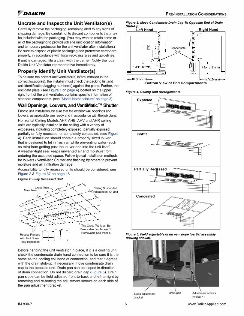
Before hanging the unit ventilator in place, if it is a cooling unit, check the condensate drain hand connection to be sure it is the same as the cooling coil hand of connection, and that it agrees with the drain stub-up. If necessary, move condensate drain cap to the opposite end. Drain pan can be sloped in direction of drain connection. Do not discard drain cap (Figure 5). Drain pan slope can be field adjusted front-to-back and left-to-right by removing and re-setting the adjustment screws on each side of the pan adjustment bracket.
Figure 3: Move Condensate Drain Cap To Opposite End of Drain Stub-Up.
Bottom View of End Compartments
Condensate Drain
Left Hand Right Hand
Figure 4: Ceiling Unit Arrangements
Exposed
Soffit
Partially Recessed
Concealed
Figure 5: Field adjustable drain pan slope (partial assembly drawing shown).
Slope adjustment bracket
Drain pan Adjustment screws (typical 4)
www.DaikinApplied.com 7 IM 830-7
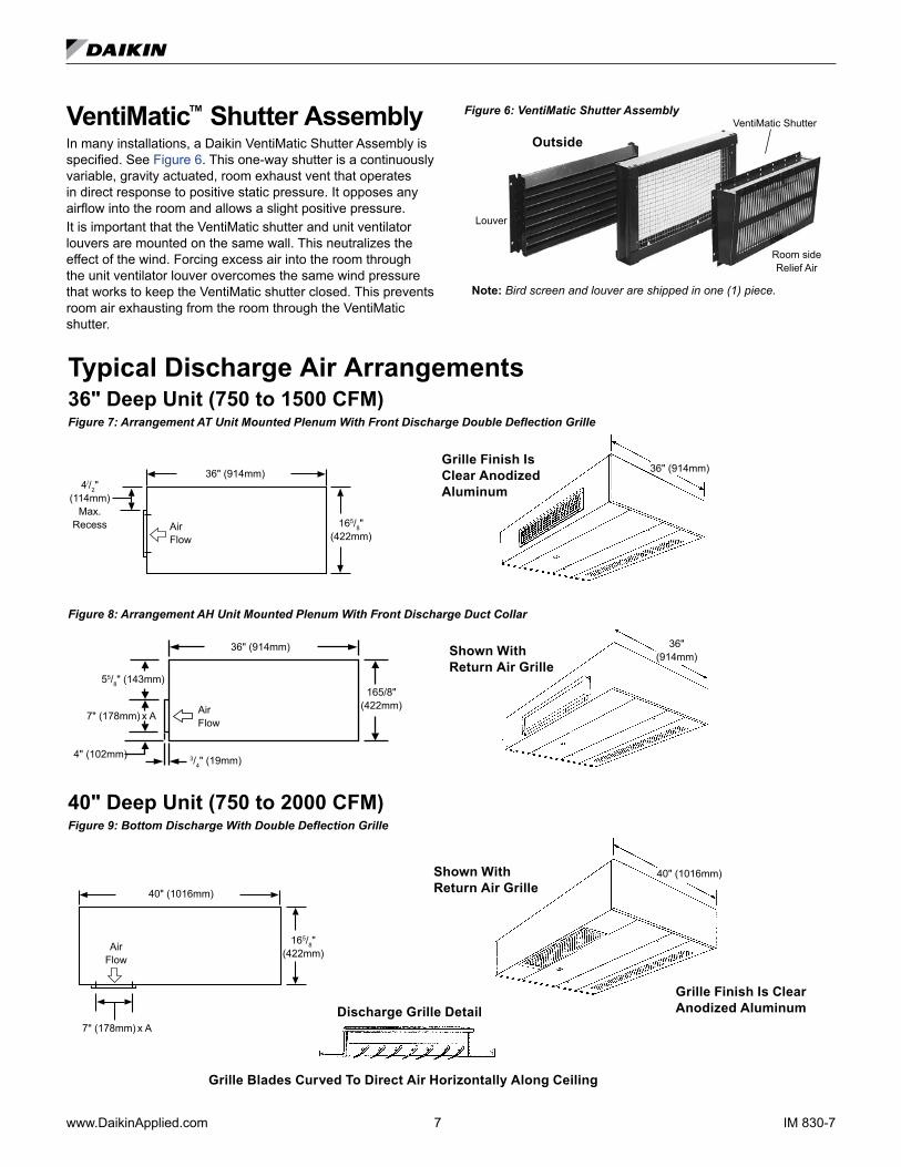
VentiMatic™ Shutter AssemblyIn many installations, a Daikin VentiMatic Shutter Assembly is specified. See Figure 6. This one-way shutter is a continuously variable, gravity actuated, room exhaust vent that operates in direct response to positive static pressure. It opposes any airflow into the room and allows a slight positive pressure. It is important that the VentiMatic shutter and unit ventilator louvers are mounted on the same wall. This neutralizes the effect of the wind. Forcing excess air into the room through the unit ventilator louver overcomes the same wind pressure that works to keep the VentiMatic shutter closed. This prevents room air exhausting from the room through the VentiMatic shutter.
Figure 6: VentiMatic Shutter Assembly
Note: Bird screen and louver are shipped in one (1) piece.
Outside
Louver
VentiMatic Shutter
Room side Relief Air
Typical Discharge Air Arrangements36" Deep Unit (750 to 1500 CFM)Figure 7: Arrangement AT Unit Mounted Plenum With Front Discharge Double Deflection Grille
36" (914mm)Grille Finish Is Clear Anodized Aluminum4//2"
(114mm) Max.
Recess 165/8" (422mm)
36" (914mm)
Air Flow
Figure 8: Arrangement AH Unit Mounted Plenum With Front Discharge Duct Collar
Shown With Return Air Grille
36" (914mm)
55/8" (143mm)
7" (178mm) x A
4" (102mm) 3/4" (19mm)
36" (914mm)
Air Flow
165/8" (422mm)
40" Deep Unit (750 to 2000 CFM)Figure 9: Bottom Discharge With Double Deflection Grille
165/8" (422mm)
7" (178mm) x A
40" (1016mm)
Air Flow
Shown With Return Air Grille
40" (1016mm)
Grille Finish Is Clear Anodized AluminumDischarge Grille Detail
Grille Blades Curved To Direct Air Horizontally Along Ceiling

IM 830-7 8 www.DaikinApplied.com
40" Deep Unit (750 to 2000 CFM)Figure 10: Arrangement FG Unit Mounted Plenum With Front Discharge Double Deflection Grille
4//2" (114mm)
Max. Recess 165/8"
(422mm)
40" (1016mm)
Air Flow
40" (1016mm)
(2000 cfm Unit Only)
Figure 11: Arrangement FD Unit Mounted Plenum With Front Discharge Duct Collar
55/8" (143mm)
7" (178mm) x A
4" (102mm)
3/4" (19mm)
Air Flow
40" (1016mm)
165/8" (422mm)
NOTE: 1. For all recessed applications (full or partial) it is necessary to
carefully examine both the inlet air and the discharge air physical locations. This must be done for each location individually and in combination with each other to ensure they are compatible with the specific installation.
2. Duct collars shipped loose for field installation not by Daikn.3. It is important also to verify there is sufficient clearance to open
and remove the bottom access panels and end panels for routine maintenance.
4. All dimensions approximated.
40" (1016mm)
(2000 cfm Unit Only)
www.DaikinApplied.com 9 IM 830-7
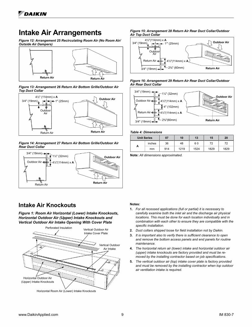
Intake Air ArrangementsFigure 12: Arrangement 25 Recirculating Room Air (No Room Air/Outside Air Dampers)
Return Air Return Air
Figure 13: Arrangement 26 Return Air Bottom Grille/Outdoor Air Top Duct Collar
Outdoor Air
Return Air
1" (25mm)4½" (114mm) x A
Outdoor Air
Return Air
3/4" (19mm)
Figure 14: Arrangement 27 Return Air Bottom Grille/Outdoor Air Rear Duct Collar
Outdoor Air
Return Air
3/4" (19mm) 1¼" (32mm)
Return Air
4½"(114mm) x A
Outdoor Air
Figure 15: Arrangement 28 Return Air Rear Duct Collar/Outdoor Air Top Duct Collar
Outdoor Air
Return Air
3/4" (19mm)
Outdoor Air
Return Air
3/4" (19mm) 4½"(114mm) x A
11" (25mm)
4½"(114mm) x A
2⅜" (60mm)
Figure 16: Arrangement 29 Return Air Rear Duct Collar/Outdoor Air Rear Duct Collar
1¼" (32mm)
4" (102mm)
Outdoor Air
Return Air
3/4" (19mm)
3/4" (19mm)
4½"(114mm) x A
4½"(114mm) x A
2⅜"(60mm)
Outdoor Air
Return Air
Table 4: DimensionsUnit Series 07 10 13 15 20
Ainches 36 48 6 0 72 72
mm 914 1219 1524 1829 1829
Note: All dimensions approximated.
Intake Air KnockoutsFigure 1: Room Air Horizontal (Lower) Intake Knockouts, Horizontal Outdoor Air (Upper) Intake Knockouts and Vertical Outdoor Air Intake Opening With Cover Plate
Horizontal Room Air (Lower) Intake Knockouts
Horizontal Outdoor Air (Upper) Intake Knockouts
Vertical Outdoor Air Intake Cover Plate
Perforated Insulation
Vertical Outdoor Air Intake
Notes: 1. For all recessed applications (full or partial) it is necessary to
carefully examine both the inlet air and the discharge air physical locations. This must be done for each location individually and in combination with each other to ensure they are compatible with the specific installation.
2. Duct collars shipped loose for field installation not by Daikin.3. It is important also to verify there is sufficient clearance to open
and remove the bottom access panels and end panels for routine maintenance.
4. The horizontal return air (lower) intake and horizontal outdoor air (upper) intake knockouts are factory provided and must be re-moved by the installing contractor based on job specifications.
5. The vertical outdoor air (top) intake cover plate is factory provided and must be removed by the installing contractor when top outdoor air ventilation intake is required.

IM 830-7 10 www.DaikinApplied.com
Vertical Outdoor Air (Top) Intake Duct Collar InstallationRemove the portion of the perforated insulation covering the vertical outdoor intake cover plate. Remove the screws securing the cover plate (number of screws vary by unit size). Remove the cover plate and install the duct flange as shown in Figure 17.Figure 17: Vertical Outdoor Air (Top) Intake Duct Collar Details
Vertical outdoor air (top) intake
Center duct collar angle over intake opening. Use as template and drill .125" dia. holes. Attach duct collar angles with provided #8 sheet metal screws.
#8 x 1-1/4" screws. Holes provided in channel. Number of screws vary by unit size.
Attach angles to unit at holes nearest to the edge.
Horizontal Outdoor Air (Upper) Intake Duct Collar InstallationRemove the upper knockout panel using a hammer and flat screw driver or punch. Install the duct flange as shown in Figure 18 or Figure 20 on page 11.Figure 18: Horizontal Outdoor Air (Top) Intake Duct Collar Details
Attach angles to unit at holes nearest to the edge.
#8 x 1-1/4" screws locate within slots on the bottom duct collar angle. Holes provided. Number of screws vary by unit size.
Center duct collar angles over intake opening. Use as template and drill .125" dia. holes. Attach duct collar angle with provided #8 sheet metal screws.
Horizontal outdoor air (upper) intake
www.DaikinApplied.com 11 IM 830-7
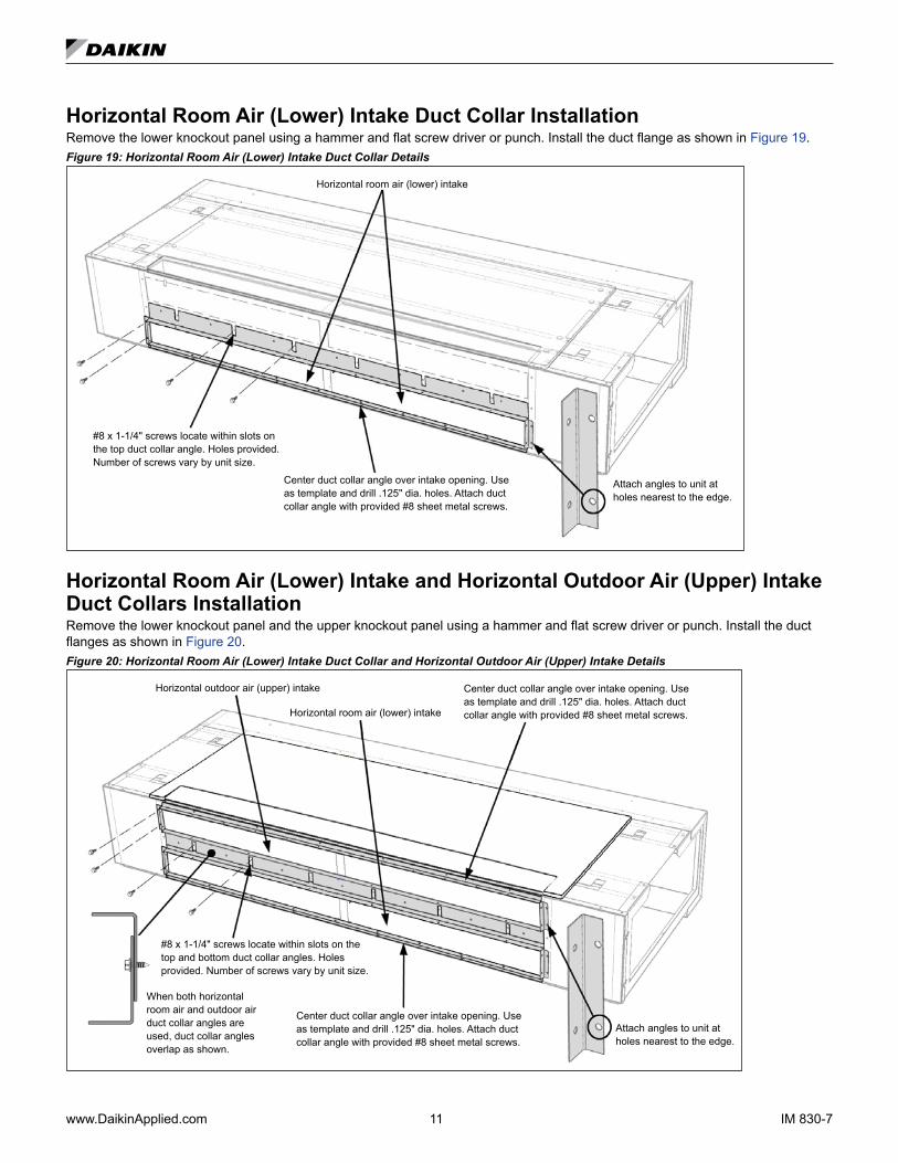
Horizontal Room Air (Lower) Intake Duct Collar InstallationRemove the lower knockout panel using a hammer and flat screw driver or punch. Install the duct flange as shown in Figure 19. Figure 19: Horizontal Room Air (Lower) Intake Duct Collar Details
Horizontal room air (lower) intake
Center duct collar angle over intake opening. Use as template and drill .125" dia. holes. Attach duct collar angle with provided #8 sheet metal screws.
Attach angles to unit at holes nearest to the edge.
#8 x 1-1/4" screws locate within slots on the top duct collar angle. Holes provided. Number of screws vary by unit size.
Horizontal Room Air (Lower) Intake and Horizontal Outdoor Air (Upper) Intake Duct Collars InstallationRemove the lower knockout panel and the upper knockout panel using a hammer and flat screw driver or punch. Install the duct flanges as shown in Figure 20. Figure 20: Horizontal Room Air (Lower) Intake Duct Collar and Horizontal Outdoor Air (Upper) Intake Details
Attach angles to unit at holes nearest to the edge.
Center duct collar angle over intake opening. Use as template and drill .125" dia. holes. Attach duct collar angle with provided #8 sheet metal screws.
Center duct collar angle over intake opening. Use as template and drill .125" dia. holes. Attach duct collar angle with provided #8 sheet metal screws.
Horizontal outdoor air (upper) intake
Horizontal room air (lower) intake
#8 x 1-1/4" screws locate within slots on the top and bottom duct collar angles. Holes provided. Number of screws vary by unit size.
When both horizontal room air and outdoor air duct collar angles are used, duct collar angles overlap as shown.
IM 830-7 12 www.DaikinApplied.com
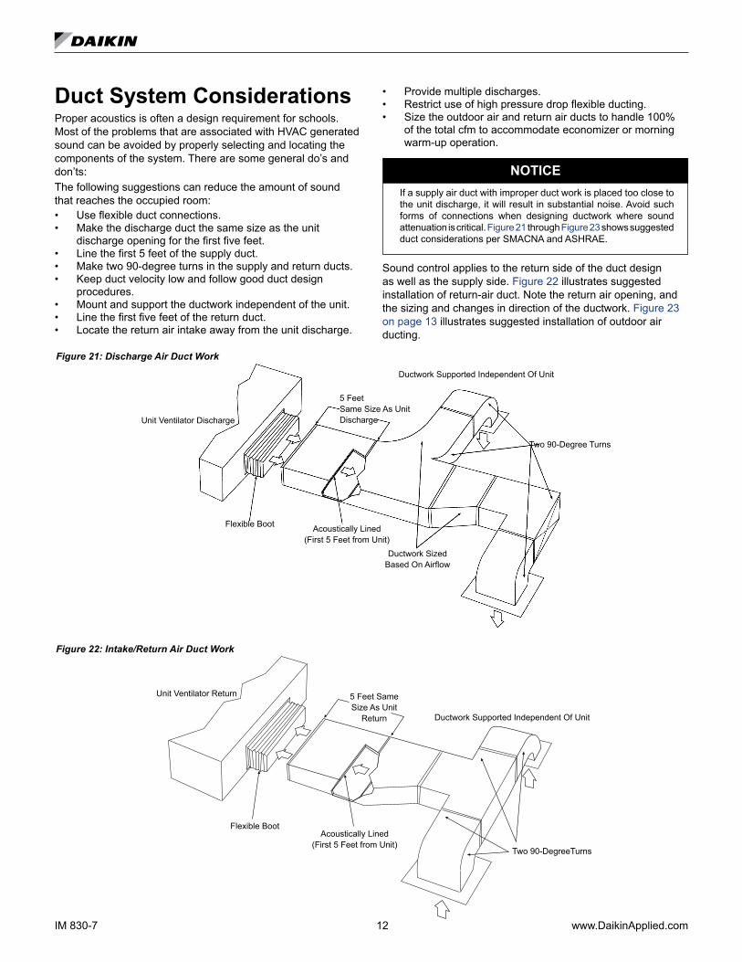
Duct System ConsiderationsProper acoustics is often a design requirement for schools. Most of the problems that are associated with HVAC generated sound can be avoided by properly selecting and locating the components of the system. There are some general do’s and don’ts:The following suggestions can reduce the amount of sound that reaches the occupied room:• Use flexible duct connections.• Make the discharge duct the same size as the unit
discharge opening for the first five feet.• Line the first 5 feet of the supply duct.• Make two 90-degree turns in the supply and return ducts.• Keep duct velocity low and follow good duct design
procedures.• Mount and support the ductwork independent of the unit.• Line the first five feet of the return duct.• Locate the return air intake away from the unit discharge.
• Provide multiple discharges.• Restrict use of high pressure drop flexible ducting.• Size the outdoor air and return air ducts to handle 100%
of the total cfm to accommodate economizer or morning warm-up operation.
NOTICEIf a supply air duct with improper duct work is placed too close to the unit discharge, it will result in substantial noise. Avoid such forms of connections when designing ductwork where sound attenuation is critical. Figure 21 through Figure 23 shows suggested duct considerations per SMACNA and ASHRAE.
Sound control applies to the return side of the duct design as well as the supply side. Figure 22 illustrates suggested installation of return-air duct. Note the return air opening, and the sizing and changes in direction of the ductwork. Figure 23 on page 13 illustrates suggested installation of outdoor air ducting.
Figure 21: Discharge Air Duct Work
Flexible Boot
5 Feet Same Size As Unit Discharge
Acoustically Lined (First 5 Feet from Unit)
Two 90-Degree Turns
Ductwork Sized Based On Airflow
Ductwork Supported Independent Of Unit
Unit Ventilator Discharge
Figure 22: Intake/Return Air Duct Work
Acoustically Lined (First 5 Feet from Unit)
Flexible Boot
Ductwork Supported Independent Of Unit
Two 90-DegreeTurns
5 Feet Same Size As Unit
Return
Unit Ventilator Return
www.DaikinApplied.com 13 IM 830-7
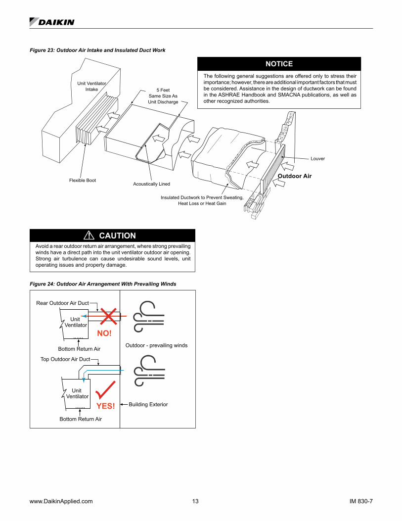
Figure 23: Outdoor Air Intake and Insulated Duct Work
The following general suggestions are offered only to stress their importance; however, there are additional important factors that must be considered. Assistance in the design of ductwork can be found in the ASHRAE Handbook and SMACNA publications, as well as other recognized authorities.
Flexible Boot
5 Feet Same Size As Unit Discharge
Acoustically Lined
Insulated Ductwork to Prevent Sweating, Heat Loss or Heat Gain
Unit Ventilator Intake
Louver
Outdoor Air
NOTICE
CAUTION!Avoid a rear outdoor return air arrangement, where strong prevailing winds have a direct path into the unit ventilator outdoor air opening. Strong air turbulence can cause undesirable sound levels, unit operating issues and property damage.
Figure 24: Outdoor Air Arrangement With Prevailing Winds
Unit Ventilator
Unit Ventilator
Top Outdoor Air Duct
Bottom Return Air
NO!
YES!Bottom Return Air
Rear Outdoor Air Duct
Outdoor - prevailing winds
Building Exterior

IM 830-7 14 www.DaikinApplied.com
CAUTION!Locate Drain Lip at bottom of vertical louver to allow proper drainage. For horizontal louvers, the louver blades should face down for proper drainage. Bird screen should always be on side toward unit.
Figure 27: Rear of Horizontal Blade Louver with Bird screens and Flange.
Installing LouversLouver DetailsFigure 25: Horizontal and Vertical Blade Louvers, Without Flange, (see Caution below for louver blade orientation and drainage)
Vertical Blade LouverHorizontal Blade Louver
Outside Air
Outside Air
Bird Screen On Side Toward Unit
Bottom
Figure 26: Horizontal and Vertical Blade Louvers, Without Flanges With Grille or With Flange Without Grille
Louver drain lipGrille/Louver with weep hole
Flange
Flange
Outside Air
Vertical Louver with Flange, without Grille
Horizontal Louver without Flange, with Grille
www.DaikinApplied.com 15 IM 830-7
Typical Installation MethodsIf the fresh air opening has not yet been made, see Figure 25 through Figure 35 for the recommended locations and the job-specific plans for the exact location. Follow local codes.Cut the wall opening so that it is slightly larger than the louver being installed. For dimensions, see Table 5. If the opening is already there, measure to be sure there is a minimum of 3/8" (9mm) clearance around all sides. For masonry installations, a lintel must be installed above all louvers. In most applications, the job specifications require ductwork connection between the louver and the unit. When using ductwork, properly caulk it to ensure a weather-tight seal. This is critical in preventing freeze-ups, cold drafts, and air infiltration. Be sure the wall is smooth, square, and provides a suitable mating surface (see Figure 28 & Figure 29).Table 5: Recommended Wall Openings For Wall Louvers
BSee
Figure 33 on page
16
C See
Figure 34 on page
17
Recommended wall openings for
wall louvers
Maximum number of VentiMatic
shutters which can be mounted
on standard louver
VentiMatic Shutter(s)
air capacity (maximum)
Length Height 24" Shutter
36" Shutter cfm L/s
24" 27" 24⅝" 10⅞" 1 0 500 236
36" 39" 36⅝" 10⅞" 0 1 750 354
48" 51" 48⅝" 10⅞" 2 0 1000 472
60" 63" 60⅝" 10⅞" 1 1 1250 590
72" 75" 72⅝" 19⅞" 0 2 1500 708
Before setting the louver, construct a sloping, sealed cement mortar base to drain unwanted moisture to the outside, (see Figure 28). Be sure the mortar base is 1" (25mm) thick at the unit and tapers toward the louver. This is critical in preventing water leaks. Be sure the sealed cement mortar base is smooth and flush with the interior wall.Figure 28: Typical Louver Installation with Sloping Sealed Cement Mortar Base
Ducting
Sealed Cement Mortar; Pitch Away From Unit
Insulation
Wall
Louver
No Caulk
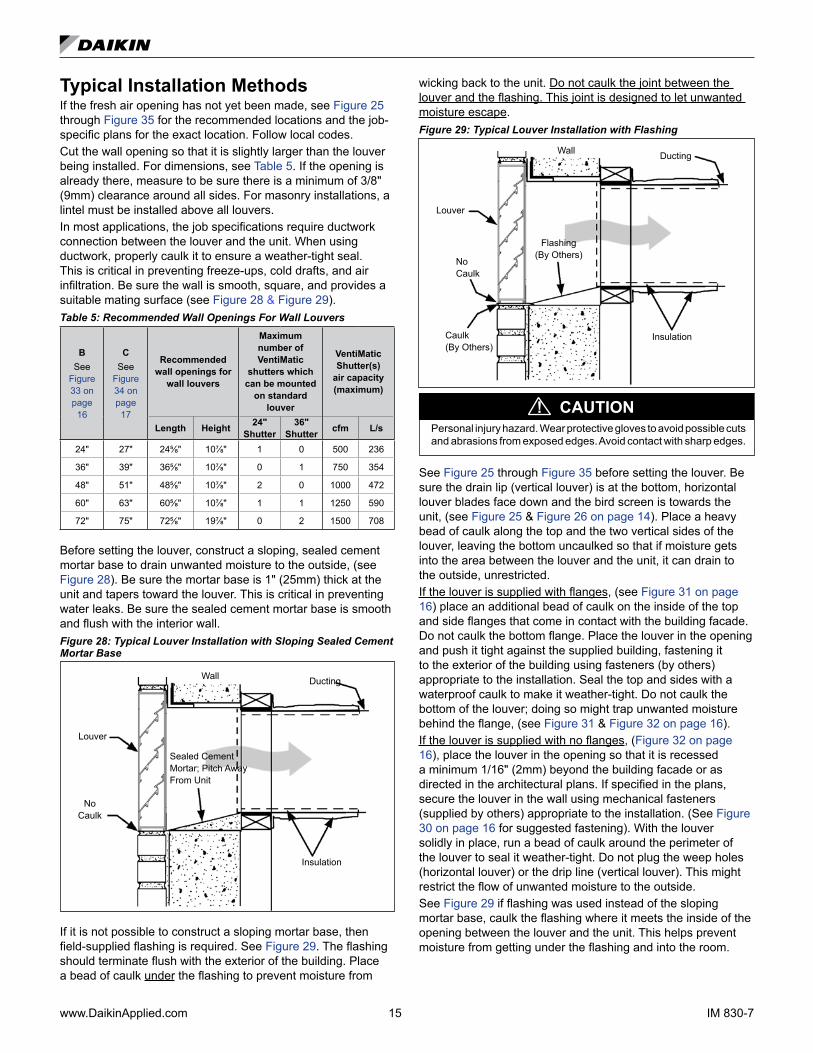
If it is not possible to construct a sloping mortar base, then field-supplied flashing is required. See Figure 29. The flashing should terminate flush with the exterior of the building. Place a bead of caulk under the flashing to prevent moisture from
wicking back to the unit. Do not caulk the joint between the louver and the flashing. This joint is designed to let unwanted moisture escape. Figure 29: Typical Louver Installation with Flashing
Louver
No Caulk
DuctingWall
InsulationCaulk (By Others)
Flashing (By Others)
CAUTION!Personal injury hazard. Wear protective gloves to avoid possible cuts and abrasions from exposed edges. Avoid contact with sharp edges.
See Figure 25 through Figure 35 before setting the louver. Be sure the drain lip (vertical louver) is at the bottom, horizontal louver blades face down and the bird screen is towards the unit, (see Figure 25 & Figure 26 on page 14). Place a heavy bead of caulk along the top and the two vertical sides of the louver, leaving the bottom uncaulked so that if moisture gets into the area between the louver and the unit, it can drain to the outside, unrestricted. If the louver is supplied with flanges, (see Figure 31 on page 16) place an additional bead of caulk on the inside of the top and side flanges that come in contact with the building facade. Do not caulk the bottom flange. Place the louver in the opening and push it tight against the supplied building, fastening it to the exterior of the building using fasteners (by others) appropriate to the installation. Seal the top and sides with a waterproof caulk to make it weather-tight. Do not caulk the bottom of the louver; doing so might trap unwanted moisture behind the flange, (see Figure 31 & Figure 32 on page 16).If the louver is supplied with no flanges, (Figure 32 on page 16), place the louver in the opening so that it is recessed a minimum 1/16" (2mm) beyond the building facade or as directed in the architectural plans. If specified in the plans, secure the louver in the wall using mechanical fasteners (supplied by others) appropriate to the installation. (See Figure 30 on page 16 for suggested fastening). With the louver solidly in place, run a bead of caulk around the perimeter of the louver to seal it weather-tight. Do not plug the weep holes (horizontal louver) or the drip line (vertical louver). This might restrict the flow of unwanted moisture to the outside. See Figure 29 if flashing was used instead of the sloping mortar base, caulk the flashing where it meets the inside of the opening between the louver and the unit. This helps prevent moisture from getting under the flashing and into the room.

IM 830-7 16 www.DaikinApplied.com
Figure 30: Suggested method for fastening louver (without flange inside wall opening.
Wall Opening
Louver (Bird Screen Not Shown)
Angle Iron (by others)
Room Side
Exterior
Figure 31: Louver Installation with FlangeCaulk
(Top and 2 Sides)
Louvers
Drain Holes (Do Not Block)
Flange (4 Sides)
1" Minimum
Lintels (By Others)
Bird ScreenSealed Cement Mortar Pitched Away from Unit Toward Louver
Vertical or Horizontal Blade Wall Intake Louver (Vertical Blade Shown)
Figure 32: Louver Installation Recessed without Flange
Drain Holes (Do Not Block With Mortar or Caulking Materials
Bird Screen
Sealed Cement Mortar Pitched Away from Unit Toward Louver
1" Minimum
Lintels (By Others)
Louvers
Vertical or Horizontal Blade Wall Intake Louver (Horizontal Blade Shown)
Installing the VentiMatic Shutter AssemblyThe VentiMatic Shutter Assembly is mounted on an installed wall louver. For larger units with 100% ventilation air dampers, two VentiMatic Shutters may be mounted side by side on the same louver. See Figure 35 on page 17. The size and appearance of the wall louvers and the VentiMatic Shutter are identical, with or without optional grilles used with the unit ventilatorWhen installing VentiMatic Shutter(s) on the wall louver, make sure all moving parts are free to operate unobstructed and placed level and plumb for proper operation. If optional steel interior wall grille is furnished, install as shown in Figure 33.Figure 33: Louver, VentiMatic Shutter, Interior Wall Grille Details, Dimensions
C (see Table 5 on page 15)
As Directed By Architect
3⁄4" (19mm) Approx.
7" (178mm) Cement Mortar
Steel Interior Wall Grille(Optional)
See Note 3 below
125⁄8" (314mm)
3⁄4" (19mm) Approx.
BirdScreen
Do Not Block Drain Holes With Caulk or Mortar
Not Less Than 9" (229mm)
Cement Mortar
Notes:1. Horizontal blade wall louver shown. Vertical blade wall louver also
available with Ventimatic shutter.
2. Optional exterior grille matches unit ventilator wall louver in mate-rial and design. Mounted on wall louvers.
3. Optional steel interior wall grille should be used to conceal the interior wall opening whenever the Ventimatic shutter is not located behind shelf cabinets or DraftStop enclosure. Hardware to mount the interior wall grille is not included.
Wall Openings and LouversBe sure that the exterior wall openings and louvers, as applicable, are ready and in accordance with the job plans. Horizontal Ceiling Models AHF, AHV, AHR, and AHB are typically installed in the ceiling in close proximity to an outside wall containing a properly sized louver that is designed to let in outside air while preventing water (such as rain) from getting past the louver and into the unit itself. A weather-tight seal keeps unwanted air and moisture from entering the occupied space. See Figure 25 through Figure 35, and Table 5 for various louver details.

www.DaikinApplied.com 17 IM 830-7
VentiMatic Shutter Assembly – DetailsFigure 34: Single VentiMatic Shutter & Wall Louver
Aluminum Wall Louver Assembly With Bird Screen (See Note 1 below)
B
(See Table 5 on page 15)
Steel VentiMatic Shutter Assembly
4⅛" (105mm)
23⅞" (606mm)
or 35⅞" (911mm)
2" (51mm)
10⅜" (264mm)
2.14" (51mm)
Decorative Exterior Grille Also Available (See Note 2) (Bird Screen not shown)
Outside
Figure 35: Two VentiMatic Shutters & Wall Louver
Aluminum Wall Louver Assembly with Bird Screen
(See Note 1)
2.14" (51mm)
VentiMatic Shutter Assembly
Center Cover
10⅜" (264mm)
B
(See Table 5 on page 15)
Outside
Decorative Exterior Grille Also Available (See Note 2) (Bird Screen not shown)
Notes:1. Horizontal blade wall louver shown. Vertical blade wall louver also available with Ventimatic shutter.2. Optional exterior grille matches unit ventilator wall louver in material and design. Mounted on wall louvers.3. Optional steel interior wall grille should be used to conceal the interior wall opening whenever the Ventimatic shutter is not located behind shelf
cabinets or DraftStop enclosure. Hardware to mount the interior wall grille is not included.
IM 830-7 18 www.DaikinApplied.com
unIt VentIlator InstallatIon
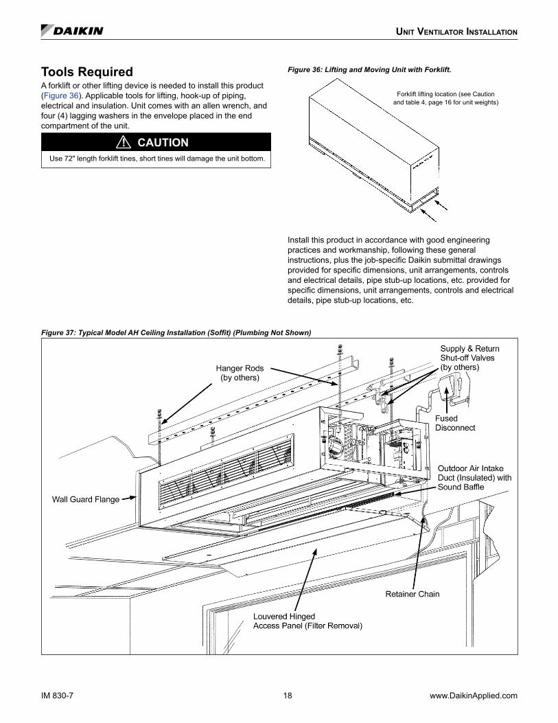
Tools RequiredA forklift or other lifting device is needed to install this product (Figure 36). Applicable tools for lifting, hook-up of piping, electrical and insulation. Unit comes with an allen wrench, and four (4) lagging washers in the envelope placed in the end compartment of the unit.
Use 72" length forklift tines, short tines will damage the unit bottom.
CAUTION!
Figure 36: Lifting and Moving Unit with Forklift.
Forklift lifting location (see Caution and table 4, page 16 for unit weights)
Install this product in accordance with good engineering practices and workmanship, following these general instructions, plus the job-specific Daikin submittal drawings provided for specific dimensions, unit arrangements, controls and electrical details, pipe stub-up locations, etc. provided for specific dimensions, unit arrangements, controls and electrical details, pipe stub-up locations, etc.
Figure 37: Typical Model AH Ceiling Installation (Soffit) (Plumbing Not Shown)
www.DaikinApplied.com 19 IM 830-7
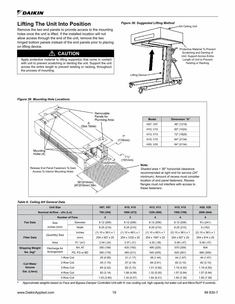
Lifting The Unit Into PositionRemove the two end panels to provide access to the mounting holes once the unit is lifted. If the installed location will not allow access through the end of the unit, remove the two hinged bottom panels instead of the end panels prior to placing on lifting device.
Apply protective material to lifting support(s) that come in contact with unit to prevent scratching or denting the unit. Support the unit across the entire length to prevent twisting or racking, throughout the process of mounting.
CAUTION!
Figure 38: Suggested Lifting Method
Lifting Device
AH Ceiling Unit
Protective Material To Prevent Scratching and Denting of Unit. Support Across Entire Length of Unit to Prevent
Twisting or Racking.
Figure 39: Mounting Hole Locations
Model Dimension "A"
H07, V07 48" (1219)
H10, V10 60" (1524)
H13, V13 72" (1829)
H15, V15 84" (2134)
H20, V20 84" (2134)
Release End Panel Fasteners To Gain Access To Interior Mounting Holes
Note: Shaded area = 36" horizontal clearance recommended at right end for service (24" minimum). Amount of recess must consider location of end panel fasteners. Recess flanges must not interfere with access to these fasteners.
Table 6: Ceiling AH General DataUnit Size H07, V07 H10, V10 H13, V13 H15, V15 H20, V20
Nominal Airflow - cfm (L/s) 750 (354) 1000 (472) 1250 (590) 1500 (708) 2000 (944)
Fan Data
Number of Fans 2 3 4 4 4
Sizeinches (mm)
Diameter 8.12 (206) 8.12 (206) 8.12 (206) 8.12 (206) 9½ (241)
Width 8.25 (210) 8.25 (210) 8.25 (210) 8.25 (210) 6 (152)
Filter Data(Quantity) Size
Inches (1) 10 x 36½ x 1 (1) 10 x 48½ x 1 (1) 10 x 60½ x 1 (2) 10 x 36½ x 1 (2) 10 x 36½ x 1
(mm) 254 x 927 x 25 254 x 1232 x 25 254 x 1587 x 25 254 x 927 x 25 254 x 914 x 25
Area Ft.2 (m2) 2.54 (.24) 3.37 (.31) 4.20 (.39) 5.08 (.47) 5.08 (.47)
Shipping Weightlbs. (kg)*
Discharge Air Arrangement
AH, AT 350 (159) 425 (193) 495 (225) 570 (259) N/A
FD, FG or BD 385 (179) 465 (211) 540 (245) 620 (281) 680 (309)
Coil Water Volume
Gal. (Liters)
1-Row Coil .25 (0.95) .31 (1.17) .38 (1.44) .44 (1.67) .44 (1.67)
2-Row Coil .45 (1.70) .57 (2.16) .69 (2.61) .82 (3.10) .82 (3.10)
3-Row Coil .64 (2.42) .82 (3.10) 1.01 (3.82) 1.19 (4.50) 1.19 (4.50)
4-Row Coil .83 (3.14) 1.08 (4.09) 1.32 (5.00) 1.57 (5.94) 1.57 (5.94)
5-Row Coil 1.03 (3.90) 1.34 (5.07) 1.64 (6.21) 1.95 (7.38) 1.95 (7.38)
* Approximate weights based on Face and Bypass Damper Controlled Unit with 4- row cooling coil, high capacity hot water coil and MicroTech® II controls.
IM 830-7 20 www.DaikinApplied.com
Anchoring The Ceiling Unit VentilatorAnchor the unit using the four unit mounting holes. The unit must be suspended from these holes (Figure 39 on page 19). Do not attempt to suspend the unit at any other locations. When hanging the horizontal AH unit ventilator, the unit should be level both front to back and side to side. This aids in condensate removal from the drain pan, and reduction of sound and vibration. Use an 8 foot level to determine the unit is not twisted or pitched.
Unit must be anchored to an internal ceiling column or other suitable support. Anchoring the unit improperly can result in personal injury, damage to property, and impact unit performance.
CAUTION!
Refer to Figure 37 on page 18 and Figure 39 on page 19 and attach the unit ventilator to the ceiling through the four (4) 7/8" (22.2 mm) diameter mounting holes provided, using field-supplied fasteners appropriate to the ceiling construction and the washers provided in the brown envelope with these instructions. The envelope also contains an allen wrench to provide access to the unit. These holes must be used to suspend the unit. Do not attempt to suspend the unit from any other points. Hanger rods are normally used to suspend the unit, (see Figure 37 on page 18). It is the responsibility of the installer to provide mounting hardware in accordance with local codes.
Ensure that the unit is properly level and not twisted. Use the unit mounting holes. Do not attempt to suspend the unit from any other points. A twisted and unlevel unit will cause poor performance due to vibration.
CAUTION!
Use an 8 foot level to ensure front to back and side to side are level. Twisting can result in unit vibration due to out of alignment of rotating components (fans, fan shaft, and motor). This can also cause premature motor failure.
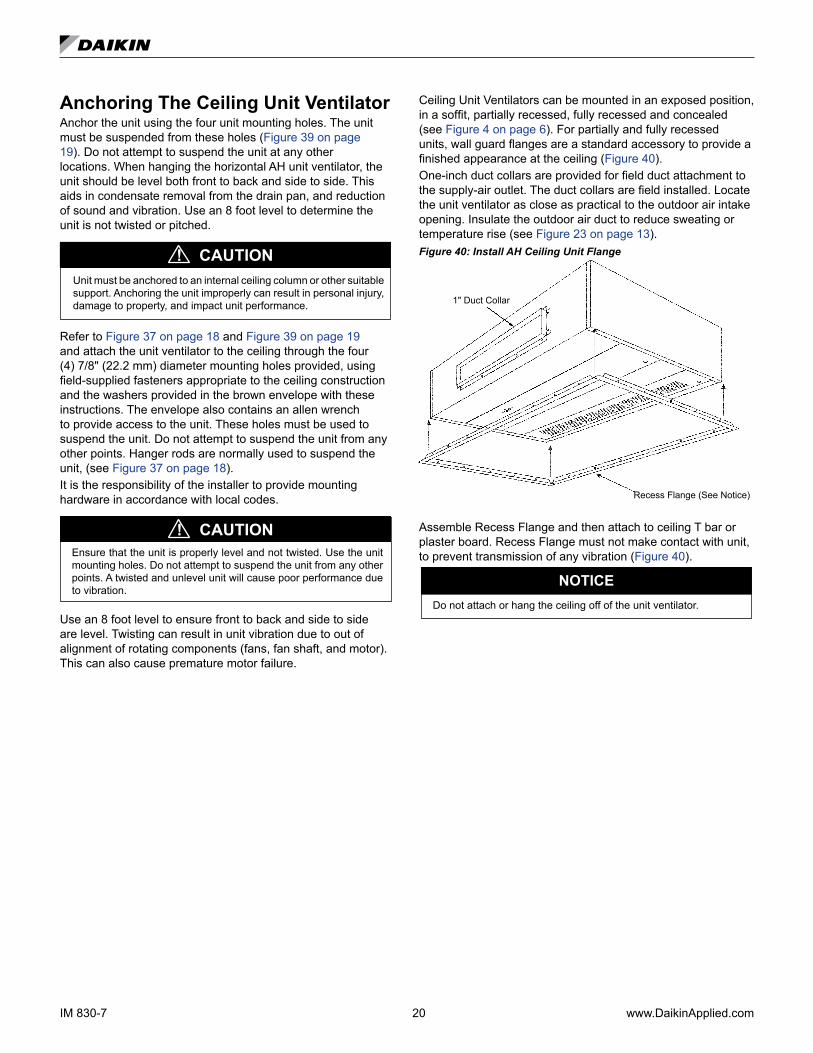
Ceiling Unit Ventilators can be mounted in an exposed position, in a soffit, partially recessed, fully recessed and concealed (see Figure 4 on page 6). For partially and fully recessed units, wall guard flanges are a standard accessory to provide a finished appearance at the ceiling (Figure 40). One-inch duct collars are provided for field duct attachment to the supply-air outlet. The duct collars are field installed. Locate the unit ventilator as close as practical to the outdoor air intake opening. Insulate the outdoor air duct to reduce sweating or temperature rise (see Figure 23 on page 13).Figure 40: Install AH Ceiling Unit Flange
Recess Flange (See Notice)
1" Duct Collar
Assemble Recess Flange and then attach to ceiling T bar or plaster board. Recess Flange must not make contact with unit, to prevent transmission of any vibration (Figure 40).
Do not attach or hang the ceiling off of the unit ventilator.
NOTICE
www.DaikinApplied.com 21 IM 830-7
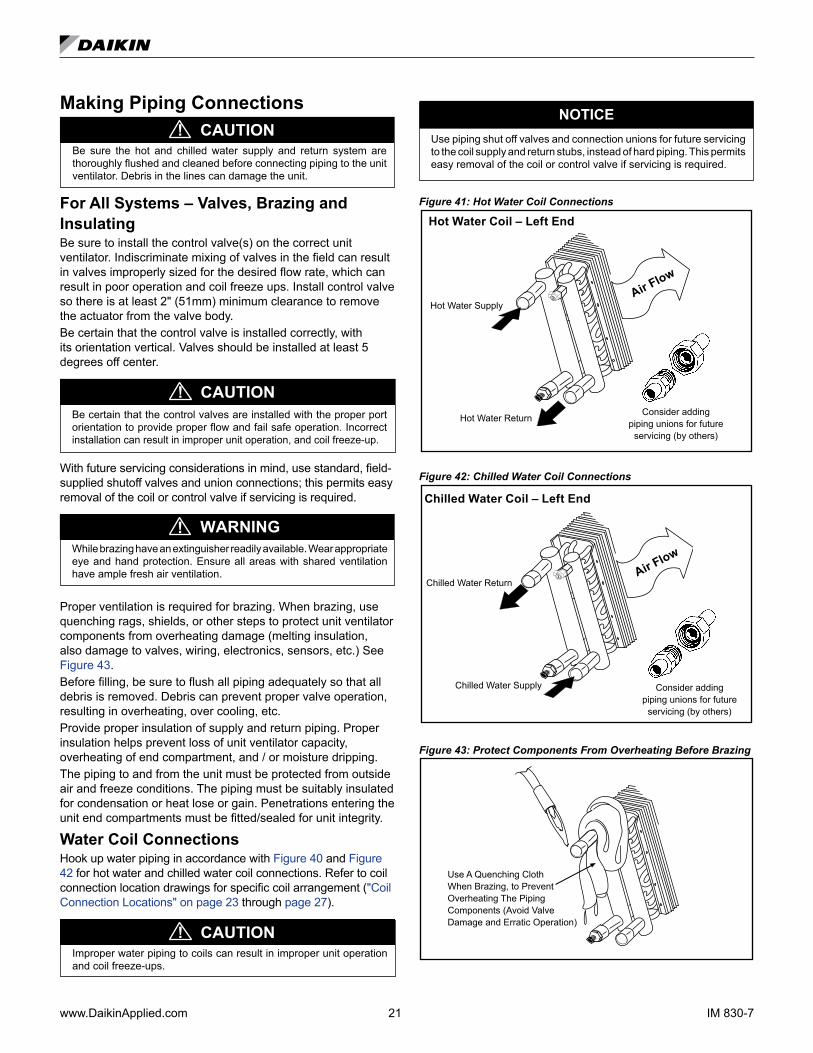
Making Piping Connections
CAUTION!Be sure the hot and chilled water supply and return system are thoroughly flushed and cleaned before connecting piping to the unit ventilator. Debris in the lines can damage the unit.
For All Systems – Valves, Brazing and InsulatingBe sure to install the control valve(s) on the correct unit ventilator. Indiscriminate mixing of valves in the field can result in valves improperly sized for the desired flow rate, which can result in poor operation and coil freeze ups. Install control valve so there is at least 2" (51mm) minimum clearance to remove the actuator from the valve body.Be certain that the control valve is installed correctly, with its orientation vertical. Valves should be installed at least 5 degrees off center.
CAUTION!Be certain that the control valves are installed with the proper port orientation to provide proper flow and fail safe operation. Incorrect installation can result in improper unit operation, and coil freeze-up.
With future servicing considerations in mind, use standard, field-supplied shutoff valves and union connections; this permits easy removal of the coil or control valve if servicing is required.
WARNING!While brazing have an extinguisher readily available. Wear appropriate eye and hand protection. Ensure all areas with shared ventilation have ample fresh air ventilation.
Proper ventilation is required for brazing. When brazing, use quenching rags, shields, or other steps to protect unit ventilator components from overheating damage (melting insulation, also damage to valves, wiring, electronics, sensors, etc.) See Figure 43.Before filling, be sure to flush all piping adequately so that all debris is removed. Debris can prevent proper valve operation, resulting in overheating, over cooling, etc. Provide proper insulation of supply and return piping. Proper insulation helps prevent loss of unit ventilator capacity, overheating of end compartment, and / or moisture dripping.The piping to and from the unit must be protected from outside air and freeze conditions. The piping must be suitably insulated for condensation or heat lose or gain. Penetrations entering the unit end compartments must be fitted/sealed for unit integrity.
Water Coil ConnectionsHook up water piping in accordance with Figure 40 and Figure 42 for hot water and chilled water coil connections. Refer to coil connection location drawings for specific coil arrangement ("Coil Connection Locations" on page 23 through page 27).
CAUTION!Improper water piping to coils can result in improper unit operation and coil freeze-ups.
NOTICEUse piping shut off valves and connection unions for future servicing to the coil supply and return stubs, instead of hard piping. This permits easy removal of the coil or control valve if servicing is required.
Figure 41: Hot Water Coil Connections
Hot Water Coil – Left End
Hot Water Return
Hot Water SupplyAir F
low
Consider adding piping unions for future
servicing (by others)
Figure 42: Chilled Water Coil Connections
Chilled Water Coil – Left End
Chilled Water Return
Chilled Water Supply
Air Flow
Consider adding piping unions for future
servicing (by others)
Figure 43: Protect Components From Overheating Before Brazing
Use A Quenching Cloth When Brazing, to Prevent Overheating The Piping Components (Avoid Valve Damage and Erratic Operation)

IM 830-7 22 www.DaikinApplied.com
For 2-Pipe Chilled Water/Hot Water SystemsInstall Water-in Temperature Sensor (OCT)After making the piping connections, securely attach and insulate the water-in temperature sensor (OCT) to the water coil supply line (refer to "Typical Piping Arrangements" on page 35). The sensor should be located on the water supply line in an area where there is continuous water flow. The sensor hangs loose in the same end compartment as the coil connections. This sensor must be attached correctly for proper unit operation.
WARNING!Water system under pressure. Keep face and body parts well away from vent. Water pressure can result in severe personal injury.
This unit has an auto air vent.1. To vent manually at initial operation: unscrew knurled head
(counter-clockwise) one or two turns. After manual venting, tighten (clockwise) knurled head firmly. The auto vent will work automatically.
2. The first time it is put into operation, a few drops of water may escape, afterwards the auto vent will be tight.
3. If dirt has entered the knurled head, disassemble clean and screw back in firmly (a built-in check valve will prevent leakage).
CAUTION!
Figure 44: Auto Vent and Drain Plug (Chilled Water Coil Shown)
Vent
Drain Plug
Suggested Condensate TrappingDaikin cooling unit ventilators are designed for condensate removal into a condensate disposal system. Do not connect the unit drain connection so that condensate exits to the outside and/or is exposed to freezing temperatures. Installer is responsible for any damage that might be caused from freezing condensate. In applications with an end compartment auxiliary drain pan, see the installation instructions shipped with the auxiliary drain pan itself.
NOTICEEach unit application is unique. Trapping may vary, or may not be required for some applications.
Consideration should be given to trapping when a pressurized air system is providing air to the unit. The condensate trap provides for discharge of water from the unit ventilator drain pan during the cooling mode, while the water seal (water level in the condensate trap), prevents the flow of air from the unit ventilator end compartment into the coil section during normal operation. Improper trapping can lead to several problems. If the trap is too tall, negative pressure will prevent drainage, causing condensate backup. If the trap is too short the seal will be destroyed or nonexistent, producing the same effect as a non-trapped system. The trap should be constructed of 7/8" clear plastic piping. The condensate piping from the drain trap must be sloped to facilitate proper drainage. The clear plastic trap should be clamped and removable for cleaning. It may be necessary to manually fill the trap at system start-up, or to run the unit for sufficient time to build a condensate seal. The condensate trap and condensate piping drainage should be free of any foreign debris. Foreign debris can prevent proper operation resulting in condensate buildup.Figure 45: Recommended Condensate Piping
A
C
⅞" I.D. Clear Plastic
B
Drain Pan
Table 7: Condensate Drain Static Pressures
A B CHigh Static 1½" 3/4" 3⅛"
Figure 46: Condensate Drain Viewed from Bottom of Unit with Hinged Access Door Open
www.DaikinApplied.com 23 IM 830-7
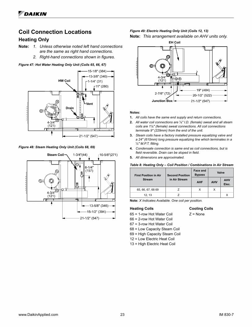
Coil Connection LocationsHeating OnlyNote: 1. Unless otherwise noted left hand connections
are the same as right hand connections. 2. Right-hand connections shown in figures.
Figure 47: Hot Water Heating Only Unit (Coils 65, 66, 67)
Figure 48: Steam Heating Only Unit (Coils 68, 69)
Figure 49: Electric Heating Only Unit (Coils 12, 13)Note: This arrangement available on AHV units only.
Notes:1. All coils have the same end supply and return connections.2. All water coil connections are ⅞" I.D. (female) sweat and all steam
coils are 1⅛" (female) sweat connections. All coil connections terminate 9" (229mm) from the end of the unit.
3. Steam coils have a factory installed pressure equalizing valve and a 24" (610mm) long pressure equalizing line which terminates in a ½" M.P.T. fitting.
4. Condensate connection is same end as coil connections, but is field reversible. Drain can be sloped in field.
5. All dimensions are approximated.
Table 8: Heating Only – Coil Position / Combinations in Air Stream
First Position in Air Stream
Second Position in Air Stream
Face and Bypass
Valve
AHF AHVAHV Elec.
65, 66, 67, 68 69 Z X X
12, 13 Z X
Note: X Indicates Available. One coil per position.
Heating Coils Cooling Coils65 = 1-row Hot Water Coil Z = None66 = 2-row Hot Water Coil67 = 3-row Hot Water Coil68 = Low Capacity Steam Coil69 = High Capacity Steam Coil12 = Low Electric Heat Coil13 = High Electric Heat Coil
IM 830-7 24 www.DaikinApplied.com
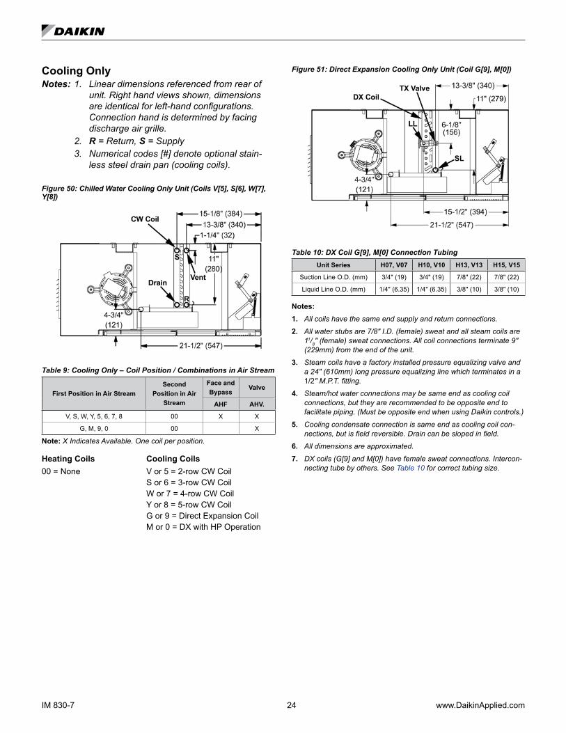
Cooling OnlyNotes: 1. Linear dimensions referenced from rear of
unit. Right hand views shown, dimensions are identical for left-hand configurations. Connection hand is determined by facing discharge air grille.
2. R = Return, S = Supply 3. Numerical codes [#] denote optional stain-
less steel drain pan (cooling coils). Figure 50: Chilled Water Cooling Only Unit (Coils V[5], S[6], W[7], Y[8])
Table 9: Cooling Only – Coil Position / Combinations in Air Stream
First Position in Air StreamSecond
Position in Air Stream
Face and Bypass
Valve
AHF AHV.
V, S, W, Y, 5, 6, 7, 8 00 X X
G, M, 9, 0 00 X
Note: X Indicates Available. One coil per position.
Heating Coils Cooling Coils00 = None V or 5 = 2-row CW Coil S or 6 = 3-row CW Coil W or 7 = 4-row CW Coil Y or 8 = 5-row CW Coil G or 9 = Direct Expansion Coil M or 0 = DX with HP Operation
Figure 51: Direct Expansion Cooling Only Unit (Coil G[9], M[0])
Table 10: DX Coil G[9], M[0] Connection TubingUnit Series H07, V07 H10, V10 H13, V13 H15, V15
Suction Line O.D. (mm) 3/4" (19) 3/4" (19) 7/8" (22) 7/8" (22)
Liquid Line O.D. (mm) 1/4" (6.35) 1/4" (6.35) 3/8" (10) 3/8" (10)
Notes:1. All coils have the same end supply and return connections.
2. All water stubs are 7/8" I.D. (female) sweat and all steam coils are 11/8" (female) sweat connections. All coil connections terminate 9" (229mm) from the end of the unit.
3. Steam coils have a factory installed pressure equalizing valve and a 24" (610mm) long pressure equalizing line which terminates in a 1/2" M.P.T. fitting.
4. Steam/hot water connections may be same end as cooling coil connections, but they are recommended to be opposite end to facilitate piping. (Must be opposite end when using Daikin controls.)
5. Cooling condensate connection is same end as cooling coil con-nections, but is field reversible. Drain can be sloped in field.
6. All dimensions are approximated.
7. DX coils (G[9] and M[0]) have female sweat connections. Intercon-necting tube by others. See Table 10 for correct tubing size.

www.DaikinApplied.com 25 IM 830-7
Chilled Water and Heating CoilsFigure 52: Chilled/Hot Water (2-pipe) Unit (Coils U[1], D[2], E[3], F[4])
Figure 53: Chilled and Hot Water Unit (Cooling Coils V[5], S[6], W[7] Y[8]; Heating Coils 65, 66, 67)
Notes:1. All coils have the same end supply and return connections. 2. All water coil connections are ⅞" I.D. (female) sweat and all steam
coils are 1⅛" (female) sweat connections. All coil connections terminate 9" (229mm) from the end of the unit.
3. Steam coils have a factory installed pressure equalizing valve and a 24" (610mm) long pressure equalizing line which terminates in a ½" M.P.T. fitting.
4. Steam/hot water connections may be same end as cooling coil con-nections, but they are recommended to be opposite end to facilitate piping. (Must be opposite end when using MicroTech controls.)
5. Condensate connection is same end as cooling coil connections, but is field reversible. Drain can be sloped in field.
6. Electric heating coil power connections are right end only. Junction box has 1" (25mm) and 2" (51mm) (trade size) knockouts, 10½" (267mm) from right end of the unit.
7. All dimensions are approximated.
Figure 54: Chilled Water & Steam Unit (Cooling Coils V[5], S[6]; Heating Coils 68, 69)
Figure 55: Chilled Water (1st Position) & Electric Heating (Cooling Coils V[5], S[6], W[7]; Heating Coil 12, 13)
Note: Electric heat, right hand only. Chilled water left hand only
Table 11: Heat / Cool Coil Position / Combinations In Air StreamFirst Position in Air Stream Second Position in Air Stream
U, D, E,F, 1, 2, 3, 4 00
65, 66, 67 V, S, 5, 6
65, 66 W, 7
V, S, 5, 6 68, 69
V, S W, 5, 6, 7 12, 13
Heating Coils Cooling Coils 65 = 1-row Hot Water Coil U or 1 = 2-row CW/HW 2-pipe66 = 2-row Hot Water Coil D or 2 = 3-row CW/HW 2-pipe67 = 3-row Hot Water Coil E or 3 = 4-row CW/HW 2-pipe68 = Low Capacity Steam Coil F or 4 = 5-row CW/HW 2-pipe69 = High Capacity Steam Coil V or 5 = 2-row CW Coil12 = Low Electric Heat Coil S or 6 = 3-row CW Coil13 = High Electric Heat Coil W or 7 = 4-row CW Coil00 = None

IM 830-7 26 www.DaikinApplied.com
ReheatNote: 1. Unless otherwise noted left hand connections
are the same as right hand connections. 2. Right-hand connections shown in figures. 3. R = Return, S = Supply 4. Numerical codes [#] denote optional stain-
less steel drain pan (cooling coils).
Figure 56: Chilled Water & Hot Water Unit (Cooling Coils V[5], S[6], W[7], Y[8]; Heating Coils 65, 66, 67)
Figure 57: Chilled Water and Steam Unit (Cooling Coils V [5], S[6]; Heating Coils 68, 69)
Figure 58: Chilled Water (1st Position) & Electric Heating (Cooling Coils V[5], S[6], W[7]; Heating Coil 12, 13)Note: Electric heat, right hand only. Chilled water left hand only
Figure 59: Direct Expansion and Hot Water Unit (Cooling Coil G[9], M[0], Heating Coils 65, 66, 67)
Table 12: Reheat Coil Position / Combinations In Air Stream
Face and Bypass Valve
First Position in Air Stream
Second Position in Air Stream AHB AHR AHR
Elec.
V, S, 5, 6 65, 66, 67, 68, 69 X X
W, 7 65, 66 X X
Y, 8 65 X X
G, M, 9, 0 65, 66, 67 68, 69 X
G, M, 9, 0 12, 13 X
V, S, W, 5, 6, 7 12, 13 X
Note: X Indicates Available. One coil per position.
Heating Coils Cooling Coils 65 = 1 Row Hot Water Coil V or 5 = 2 Row CW Coil66 = 2 Row Hot Water Coil S or 6 = 3 Row CW Coil67 = 3 Row Hot Water Coil W or 7 = 4 Row CW Coil68 = Low Capacity Steam Coil Y or 8 = 5 Row CW Coil69 = High Capacity Steam Coil G or 9 = Direct Expansion Coil12 = Low Electric Heat Coil M or 0 = DX for HP Operation13 = High Electric Heat Coil
www.DaikinApplied.com 27 IM 830-7
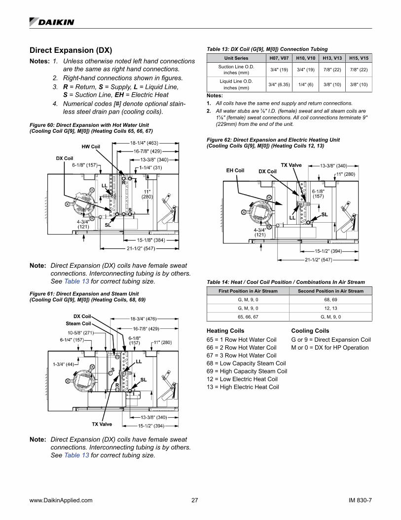
Direct Expansion (DX)Notes: 1. Unless otherwise noted left hand connections
are the same as right hand connections. 2. Right-hand connections shown in figures. 3. R = Return, S = Supply, L = Liquid Line,
S = Suction Line, EH = Electric Heat 4. Numerical codes [#] denote optional stain-
less steel drain pan (cooling coils).
Figure 60: Direct Expansion with Hot Water Unit (Cooling Coil G[9], M[0]) (Heating Coils 65, 66, 67)
Note: Direct Expansion (DX) coils have female sweat connections. Interconnecting tubing is by others. See Table 13 for correct tubing size.
Figure 61: Direct Expansion and Steam Unit (Cooling Coil G[9], M[0]) (Heating Coils, 68, 69)
Note: Direct Expansion (DX) coils have female sweat connections. Interconnecting tubing is by others. See Table 13 for correct tubing size.
Table 13: DX Coil (G[9], M[0]) Connection TubingUnit Series H07, V07 H10, V10 H13, V13 H15, V15
Suction Line O.D. inches (mm) 3/4" (19) 3/4" (19) 7/8" (22) 7/8" (22)
Liquid Line O.D. inches (mm)
3/4" (6.35) 1/4" (6) 3/8" (10) 3/8" (10)
Notes:1. All coils have the same end supply and return connections. 2. All water stubs are ⅞" I.D. (female) sweat and all steam coils are
1⅛" (female) sweat connections. All coil connections terminate 9" (229mm) from the end of the unit.
Figure 62: Direct Expansion and Electric Heating Unit (Cooling Coils G[9], M[0]) (Heating Coils 12, 13)
Table 14: Heat / Cool Coil Position / Combinations In Air StreamFirst Position in Air Stream Second Position in Air Stream
G, M, 9, 0 68, 69
G, M, 9, 0 12, 13
65, 66, 67 G, M, 9, 0
Heating Coils Cooling Coils 65 = 1 Row Hot Water Coil G or 9 = Direct Expansion Coil66 = 2 Row Hot Water Coil M or 0 = DX for HP Operation67 = 3 Row Hot Water Coil 68 = Low Capacity Steam Coil 69 = High Capacity Steam Coil 12 = Low Electric Heat Coil13 = High Electric Heat Coil
IM 830-7 28 www.DaikinApplied.com
Typical Valve PackagesThe optional factory-supplied Daikin Control Valve(s) for water applications can be either 2-way or 3-way type, and is / are shipped separate from the unit ventilator itself to help avoid shipping damage to the piping of the connection stub from the weight of the valve, and to provide the installer with maximum flexibility in making the field piping connection. Before proceeding, see Figure 63 through Figure 85 as applicable, as well as the job-specific piping drawings.
Notes: 1. See label furnished on 2-way valve to deter-mine direction of flow through the valve.
2. Adhere to the port orientation shown for the 3-way valve.
3. For hot water applications and chilled water/hot water (2-pipe) applications, the 2-way valve furnished is normally piped open to the coil; the 3-way valve is piped normally open to the coil.
4. For chilled water applications, the 2-way valve furnished is normally piped closed to the coil; the 3-way valve is piped normally closed to the coil.
5. The 3-way valve is generally selected for di-verting water back to the return main, where a constant pump head pressure is required.
6. All water coil stubs are 7/8" I.D. female sweat. Coil connections terminate 9" (229mm) from the end of the unit. Hot water connections may be same end as cooling coil connections, but are recommended to be at opposite ends from each other. When using MicroTech controls, they must be at opposite ends.
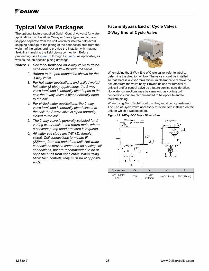
Face & Bypass End of Cycle Valves2-Way End of Cycle Valve
When piping the 2-Way End of Cycle valve, refer to label to determine the direction of flow. The valve should be installed so that there is a 2" (51mm) minimum clearance to remove the actuator from the valve body. Provide unions for removal of unit coil and/or control valve as a future service consideration. Hot water connections may be same end as cooling coil connections, but are recommended to be opposite end to facilitate piping.When using MicroTech® controls, they must be opposite end. The End of Cycle valve accessory must be field installed on the unit for which it was selected.Figure 63: 2-Way EOC Valve Dimensions
Connection Cv X Y Z
3/4" (19mm) FNPT 7.5 111/16"
(43mm)15/16" (24mm) 3⅝" (92mm)
www.DaikinApplied.com 29 IM 830-7
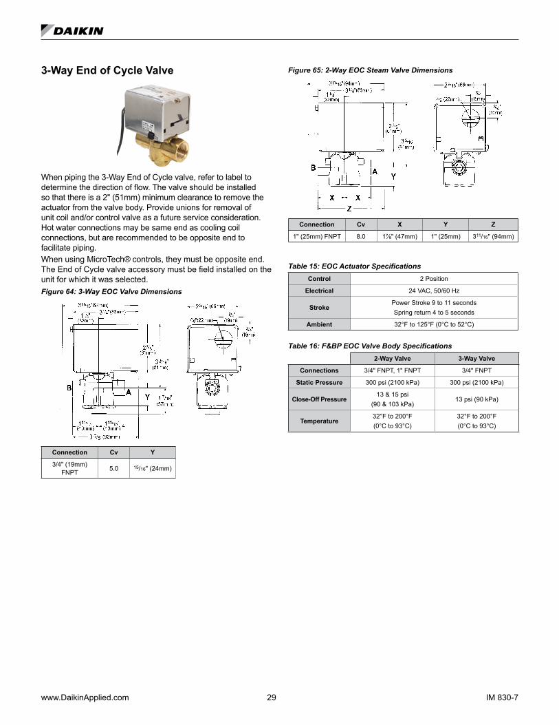
3-Way End of Cycle Valve
When piping the 3-Way End of Cycle valve, refer to label to determine the direction of flow. The valve should be installed so that there is a 2" (51mm) minimum clearance to remove the actuator from the valve body. Provide unions for removal of unit coil and/or control valve as a future service consideration. Hot water connections may be same end as cooling coil connections, but are recommended to be opposite end to facilitate piping.When using MicroTech® controls, they must be opposite end. The End of Cycle valve accessory must be field installed on the unit for which it was selected.Figure 64: 3-Way EOC Valve Dimensions
Connection Cv Y
3/4" (19mm) FNPT 5.0 15/16" (24mm)
Figure 65: 2-Way EOC Steam Valve Dimensions
Connection Cv X Y Z
1" (25mm) FNPT 8.0 1⅞" (47mm) 1" (25mm) 311/16" (94mm)
Table 15: EOC Actuator SpecificationsControl 2 Position
Electrical 24 VAC, 50/60 Hz
StrokePower Stroke 9 to 11 secondsSpring return 4 to 5 seconds
Ambient 32°F to 125°F (0°C to 52°C)
Table 16: F&BP EOC Valve Body Specifications2-Way Valve 3-Way Valve
Connections 3/4" FNPT, 1" FNPT 3/4" FNPT
Static Pressure 300 psi (2100 kPa) 300 psi (2100 kPa)
Close-Off Pressure13 & 15 psi
(90 & 103 kPa)13 psi (90 kPa)
Temperature32°F to 200°F (0°C to 93°C)
32°F to 200°F (0°C to 93°C)

IM 830-7 30 www.DaikinApplied.com
2-Way Modulating Valve (Chilled Water, Hot Water or Combination)
Two-way modulating control valves for MicroTech are designed to regulate the flow of chilled water, hot water or the combination. They consist of a nickel plated brass body and stainless steel ball valve and stem, with a spring return proportional actuator. The optional valve accessory is shipped separate from the unit ventilator for field installation to prevent shipping damage and to provide flexibility in making the field piping connection.
Figure 66: 2-Way Modulating Valve Dimensions
BA
D C
E F
AB A
Table 17: 2-Way Actuator Specifications (CW, HW, CW/HW)Power Supply 24 VAC, ±20%, 50/60 Hz, 24 VDC, ±10%
Electrical Connection 3ft [1m], 18 GA plenum cable with 1/2” conduit connector
Overload Protection electronic throughout 0° to 95° rotation
Operating Range Y 2 to 10 VDC, 4 to 20 mA w/ ZG-R01 (500 Ω, 1/4 W resistor)
Input Impedance 100 k Ω for 2 to 10 VDC (0.1 mA), 500 Ω for 4 to 20 mA
Feedback Output U 2 to 10 VDC, 0.5 mA max
Angle of Rotation Max. 95°, 90°
Position Indication visual indicator, 0° to 95° (0° is full spring return position)
Running Time (Motor) 95 sec
Running Time (Fail-Safe) <25 sec
Ambient Humidity max. 95% RH non-condensing
Ambient Temperature Range -22°F to 122°F [-30°C to 50°C]
Storage Temperature Range -40°F to 176°F [-40°C to 80°C]
Table 18: 2-Way Valve Body Specifications (CW, HW, CW/HW)Service chilled, hot water, up to 60% glycol
Flow Characteristic equal percentage
Controllable Flow Range 75°
Body Pressure Rating [psi] 600
Media Temperature Range (Water) 0°F to 250°F [-18°C to 120°C]
Max Differential Pressure (Water) 50 psi (345 kPa)
Close-Off Pressure 200 psi
Table 19: 2-Way Modulating Valve 1/2" – Dimensions (CW, HW, CW/HW)
Valve Part No. Cv Connection Size (inches) A B C D E F
B209 0.8
1/2"
6.59" (167mm) 2.38" (60mm) 4.9" (124mm) 4.32" (110mm) 1.53" (38mm)B210 1.2
B211 1.9
B212 3.0
6.59" (167mm) 2.38" (60mm) 5.48" (139mm) 4.71" (120mm) 1.53" (38mm)B213 4.7
B214 7.4
Table 20: 2-Way Modulating Water Valve 1/2" – Pressure Drop (CW, HW, CW/HW)Pressure Drop Across the Valve
2-Way CCV Part No.
Cv Maximum
Rating Connection Size 1 PSI 2 PSI 3 PSI 4 PSI 5 PSI 6 PSI 7 PSI 8 PSI 9 PSI 10 PSI
B209 0.8
1/2"
0.8 1.1 1.4 1.6 1.8 2.0 2.1 2.3 2.4 2.5
B210 1.2 1.2 1.7 2.1 2.4 2.8 2.9 3.2 3.4 3.6 3.8
B211 1.9 1.9 2.7 3.3 3.8 4.2 4.7 5.0 5.4 5.7 6.0
B212 3.0 3.0 4.2 5.2 6.0 6.8 7.3 7.9 8.5 9.0 9.5
B213 4.7 4.7 6.6 8.1 9.4 11 12 12 13 14 15
B214 7.4 7.4 10 13 15 17 18 20 21 22 23
www.DaikinApplied.com 31 IM 830-7
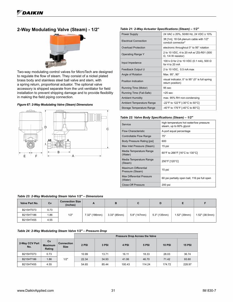
2-Way Modulating Valve (Steam) - 1/2"
Two-way modulating control valves for MicroTech are designed to regulate the flow of steam. They consist of a nickel plated brass body and stainless steel ball valve and stem, with a spring return, proportional actuator. The optional valve accessory is shipped separate from the unit ventilator for field installation to prevent shipping damage and to provide flexibility in making the field piping connection.
Figure 67: 2-Way Modulating Valve (Steam) Dimensions
FE
D
BA
AB A
C
Table 21: 2-Way Actuator Specifications (Steam) – 1/2"Power Supply 24 VAC ± 20%, 50/60 Hz, 24 VDC ± 10%
Electrical Connection 3ft [1m], 18 GA plenum cable with 1/2" conduit connector"
Overload Protection electronic throughout 0° to 95° rotation
Operating Range Y 2 to 10 VDC, 4 to 20 mA w/ ZG-R01 (500 Ω, 1/4 W resistor)
Input Impedance 100 k Ω for 2 to 10 VDC (0.1 mA), 500 Ω for 4 to 20 mA
Feedback Output U 2 to 10 VDC, 0.5 mA max
Angle of Rotation Max. 95°, 90°
Position Indication visual indicator, 0° to 95° (0° is full spring return position)
Running Time (Motor) 95 sec
Running Time (Fail-Safe) <25 sec
Ambient Humidity max. 95% RH non-condensing
Ambient Temperature Range -22°F to 122°F [-30°C to 50°C]
Storage Temperature Range -40°F to 176°F [-40°C to 80°C]
Table 22: Valve Body Specifications (Steam) – 1/2"
Service high temperature hot water/low pressure steam, up to 60% glycol
Flow Characteristic A-port equal percentage
Controllable Flow Range 75°
Body Pressure Rating [psi] 600
Max Inlet Pressure (Steam) 15 psi
Media Temperature Range (Water) 60°F to 266°F [16°C to 130°C]
Media Temperature Range (Steam) 250°F [120°C]
Maximum Differential Pressure (Steam) 15 psi
Max Differential Pressure (Water) 60 psi partially open ball, 116 psi full open
Close-Off Pressure 200 psi
Table 23: 2-Way Modulating Steam Valve 1/2" – Dimensions
Valve Part No. Cv Connection Size (inches) A B C D E F
B215HT073 0.73
1/2" 7.32" (186mm) 3.33" (85mm) 5.8" (147mm) 5.3" (135mm) 1.52" (39mm) 1.52" (38.5mm)B215HT186 1.86
B215HT455 4.55
Table 24: 2-Way Modulating Steam Valve 1/2" – Pressure DropPressure Drop Across the Valve
2-Way CCV Part No.
Cv Maximum
Rating
Connection Size 2 PSI 3 PSI 4 PSI 5 PSI 10 PSI 15 PSI
B215HT073 0.73
1/2"
10.99 13.71 16.11 18.33 28.03 36.74
B215HT186 1.86 22.34 34.93 41.06 46.70 71.42 93.60
B215HT455 4.55 54.65 85.44 100.43 114.24 174.72 228.97
IM 830-7 32 www.DaikinApplied.com
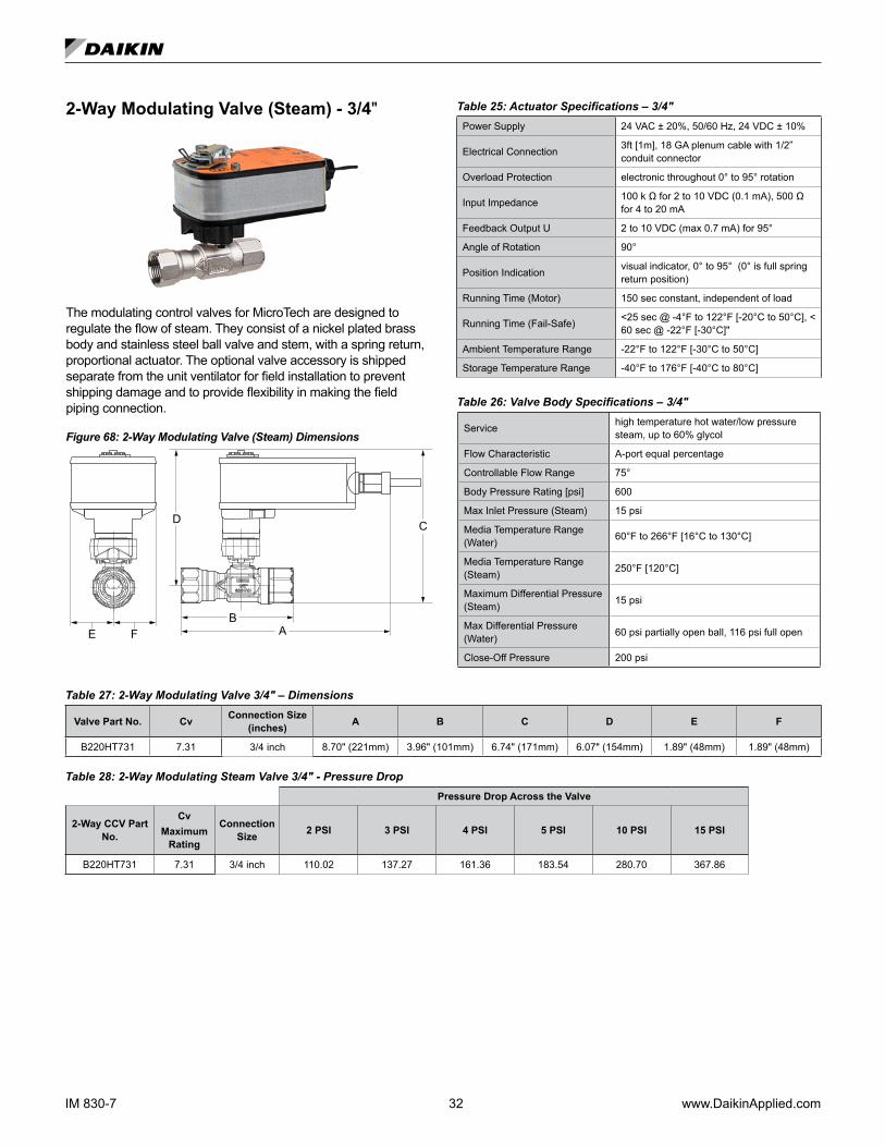
2-Way Modulating Valve (Steam) - 3/4"
The modulating control valves for MicroTech are designed to regulate the flow of steam. They consist of a nickel plated brass body and stainless steel ball valve and stem, with a spring return, proportional actuator. The optional valve accessory is shipped separate from the unit ventilator for field installation to prevent shipping damage and to provide flexibility in making the field piping connection.
Figure 68: 2-Way Modulating Valve (Steam) Dimensions
BA
D C
FE
Table 25: Actuator Specifications – 3/4"Power Supply 24 VAC ± 20%, 50/60 Hz, 24 VDC ± 10%
Electrical Connection 3ft [1m], 18 GA plenum cable with 1/2” conduit connector
Overload Protection electronic throughout 0° to 95° rotation
Input Impedance 100 k Ω for 2 to 10 VDC (0.1 mA), 500 Ω for 4 to 20 mA
Feedback Output U 2 to 10 VDC (max 0.7 mA) for 95°
Angle of Rotation 90°
Position Indication visual indicator, 0° to 95° (0° is full spring return position)
Running Time (Motor) 150 sec constant, independent of load
Running Time (Fail-Safe) <25 sec @ -4°F to 122°F [-20°C to 50°C], < 60 sec @ -22°F [-30°C]"
Ambient Temperature Range -22°F to 122°F [-30°C to 50°C]
Storage Temperature Range -40°F to 176°F [-40°C to 80°C]
Table 26: Valve Body Specifications – 3/4"
Service high temperature hot water/low pressure steam, up to 60% glycol
Flow Characteristic A-port equal percentage
Controllable Flow Range 75°
Body Pressure Rating [psi] 600
Max Inlet Pressure (Steam) 15 psi
Media Temperature Range (Water) 60°F to 266°F [16°C to 130°C]
Media Temperature Range (Steam) 250°F [120°C]
Maximum Differential Pressure (Steam) 15 psi
Max Differential Pressure (Water) 60 psi partially open ball, 116 psi full open
Close-Off Pressure 200 psi
Table 27: 2-Way Modulating Valve 3/4" – Dimensions
Valve Part No. Cv Connection Size (inches) A B C D E F
B220HT731 7.31 3/4 inch 8.70" (221mm) 3.96" (101mm) 6.74" (171mm) 6.07" (154mm) 1.89" (48mm) 1.89" (48mm)
Table 28: 2-Way Modulating Steam Valve 3/4" - Pressure DropPressure Drop Across the Valve
2-Way CCV Part No.
Cv Maximum
Rating
Connection Size 2 PSI 3 PSI 4 PSI 5 PSI 10 PSI 15 PSI
B220HT731 7.31 3/4 inch 110.02 137.27 161.36 183.54 280.70 367.86

www.DaikinApplied.com 33 IM 830-7
3-Way Modulating Valve (Chilled Water, Hot Water or Combination)
Three-way modulating control valves for MicroTech are designed to regulate the flow of hot or chilled water or the combination. They consist of a nickel plated brass body and stem with chrome plated brass ball valve, with a spring return, proportional actuator. The optional valve accessory is shipped separate from the unit ventilator for field installation to prevent shipping damage and to provide flexibility in making the field piping connection.
Figure 69: 3-Way Modulating Valve (Chilled Water, Hot Water or Combination) Dimensions
BA
CD
E F
AB A
Table 29: 3-Way Actuator Specifications (CW, HW, CW/HW)Power Supply 24 VAC, ±20%, 50/60 Hz, 24 VDC, ±10%
Electrical Connection 3ft [1m], 18 GA plenum cable with 1/2" conduit connector
Overload Protection electronic throughout 0° to 95° rotation
Operating Range Y 2 to 10 VDC, 4 to 20 mA w/ ZG-R01 (500 Ω, 1/4 W resistor)
Input Impedance 100 k Ω for 2 to 10 VDC (0.1 mA), 500 Ω for 4 to 20 mA
Feedback Output U 2 to 10 VDC, 0.5 mA max
Angle of Rotation Max. 95°, 90°
Position Indication visual indicator, 0° to 95° (0° is full spring return position)
Running Time (Motor) 95 sec
Running Time (Fail-Safe) <25 sec
Ambient Humidity max. 95% RH non-condensing
Ambient Temperature Range -22°F to 122°F [-30°C to 50°C]
Storage Temperature Range -40°F to 176°F [-40°C to 80°C]
Table 30: 3-Way Valve Body Specifications (CW, HW, CW/HW)Service chilled, hot water, up to 60% glycol
Flow Characteristic A-port Equal percentage; B-port modified linear for constant flow
Controllable Flow Range 75°
Body Pressure Rating [psi] 600
Media Temperature Range (Water) 0°F to 250°F [-18°C to 120°C]
Max Differential Pressure (Water) 50 psi (345 kPa)
Close-Off Pressure 200 psi
Table 31: 3-Way Modulating Valve 1/2″ – Dimensions
Valve Part No. Cv Connection Size (inches) A B C D E F
B309(B) 0.8
1/2"
6.59" (167mm) 2.38" (60mm) 4.9" (124mm) 4.32" (110mm) 1.53" (38mm) 1.2" (31mm)B310(B) 1.2
B311(B) 1.9
B312(B) 3.0
6.59" (167mm)2.38" (60mm) 4.9" (124mm) 4.71" (120mm) 1.53" (38mm) 1.29" (33mm)
B313(B) 4.7
B318(B) 7.4 2.73" (69mm) 5.5" (140mm) 4.8" (122mm) 1.53" (38mm) 1.47" (37mm)
Table 32: Modulating 3-Way Hot Water, Chilled Water or 2-Pipe CW/HW Valve 1/2″ – Pressure DropPressure Drop Across the Valve
3-Way CCV Part No.
Cv Maximum
Rating
Connection Size 1 PSI 2 PSI 3 PSI 4 PSI 5 PSI 6 PSI 7 PSI 8 PSI 9 PSI 10 PSI
B309(B) 0.8
1/2"
0.8 1. 1.4 1.6 1.8 2.0 2. 2.3 2.4 2.5
B310(B) 1.2 1.2 1.7 2. 2.4 2.8 2.9 3.2 3.4 3.6 3.8
B311(B) 1.9 1.9 2.7 3.3 3.8 4.2 4.7 5.0 5.4 5.7 6.0
B312(B) 3.0 3.0 4.2 5.2 6.0 6.8 7.3 7.9 8.5 9.0 9.5
B313(B) 4.7 4.7 6.6 8.1 9.4 11 12 12 13 14 15
B318(B) 7.4 7.4 10 13 15 17 18 20 21 22 23
IM 830-7 34 www.DaikinApplied.com
Steam Modulating Valve SelectionThe steam modulating control valve is expected to vary the quantity of steam through the coil. Any movement of the valve stem should produce some change in the steam flow rate. To select a modulating steam valve:
1. Obtain the supply steam inlet pressure.2. Determine the actual heat requirement of the space
to be heated.
Table 33: Modulating 2-Way, Normally Open, Steam Valves – Pressure DropPressure Drop Across the Valve
2-Way CCV Part No.
Cv Maximum
Rating
Connection Size 2 PSI 3 PSI 4 PSI 5 PSI 10 PSI 15 PSI
B215HT073 0.73
1/2"
10.99 13.71 16.11 18.33 28.03 36.74
B215HT186 1.86 22.34 34.93 41.06 46.70 71.42 93.60
B215HT455 4.55 54.65 85.44 100.43 114.24 174.72 228.97
B220HT731 7.31 3/4 inch 110.02 137.27 161.36 183.54 280.70 367.86
2-Way and 3-Way Hot Water and Chilled Water Modulating Valve SelectionThe unit ventilator control valve is expected to be able to vary the quantity of water that flows through the coil in a modulating fashion. Any movement of the valve stem should produce some change in the amount of water that flows through the coil. Oversized control valves cannot do this. For example, assume that when the control valve is fully open, the pressure drop through the coil is twice as great as the drop through the valve. In this case, the control valve must travel to approximately 50% closed before it can begin to have any influence on the water flow through the coil. The control system, no matter how sophisticated, cannot overcome this. Oversized control valves can also result in “hunting” which will shorten the life of the valve and actuator and possibly damage the coil.To correctly select the proper Chilled Water Modulating Valve:
1. Determine the flow of water and the corresponding pressure drop through the coil.
2. Obtain the pressure difference between the supply and return mains.
3. Select a valve size (Cv) from Table 28 on page 32, or Table 32 on page 33 on the basis of taking 50% of the available pressure difference (at design flow) between the supply and return mains at the valve location. The valve should have a pressure drop greater than that of the coil.
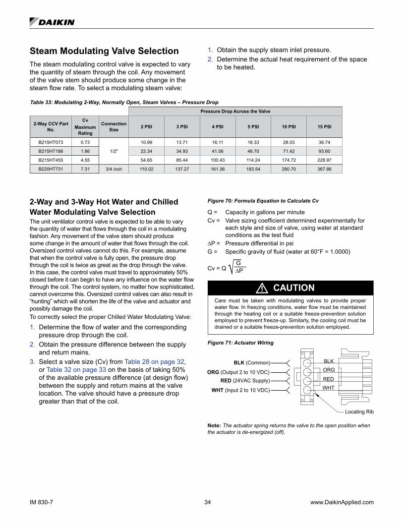
Figure 70: Formula Equation to Calculate Cv
Q = Capacity in gallons per minuteCv = Valve sizing coefficient determined experimentally for
each style and size of valve, using water at standard conditions as the test fluid
∆P = Pressure differential in psiG = Specific gravity of fluid (water at 60°F = 1.0000)
Cv = Q G ∆P
CAUTIONCare must be taken with modulating valves to provide proper water flow. In freezing conditions, water flow must be maintained through the heating coil or a suitable freeze-prevention solution employed to prevent freeze-up. Similarly, the cooling coil must be drained or a suitable freeze-prevention solution employed.
Figure 71: Actuator Wiring
WHT (Input 2 to 10 VDC)
RED (24VAC Supply)ORG (Output 2 to 10 VDC)
BLK (Common) BLK
WHT
ORG
RED
Locating Rib
Note: The actuator spring returns the valve to the open position when the actuator is de-energized (off).

www.DaikinApplied.com 35 IM 830-7
Typical Piping ArrangementsMount heating valve actuators in an upright position above the center line of the valve body and pipe actuators normally open to the coil. Modulating valve actuators for hot water applications may be positioned above the valve body a maximum of 75 degrees from the vertical. For steam applications only, mount the modulating valve actuator above the valve body at 45 degrees from the vertical. Two-position, end-of-cycle (EOC) valves used with face and bypass damper controlled units may be positioned above the valve body a maximum of 85° from the vertical. All control valves are shipped loose to help avoid shipping damage to the piping or the coil connection stub from the weight of the valve, and to provide the installing contractor with maximum flexibility in making the field piping connections. Refer to Daikin factory instruction sheet shipped with the unit for port orientation and a piping schematic. Control valves must be installed on the units in which they are shipped. Indiscriminate mixing of valves among units can result in valves not properly sized for the desired flow rate. Install control valves so that there is a 2" minimum clearance to remove the actuator from the valve body. As a future service consideration, provide unions for removal of the unit coil and/or the control valve.
Heating – Hot Water End of Cycle Valve PipingThe 2-way EOC hot water or 2-pipe Chilled Water/Hot Water valve is furnished normally open to the coil. When the valve is de-energized (off) there is full flow through the coil. Energizing the valve shuts off the water flow.
Figure 72: 2-Way EOC, Normally Open, Hot Water or 2-Pipe Chilled Water/Hot Water Valve Piping
Unions
2-wayEOC Valve
OCT Sensor(2-pipe CW/HW Units Only)
Balancing & Shutoff Valve
Unit CoilReturn
Supply
Return
Supply
A B
Shutoff Valve
The 3-way hot water or 2-pipe CW/HW valve is furnished normally open to the coil. When the valve is de-energized (off) there is full flow through the coil. Energizing the valve allows the water to bypass the coil.
Figure 73: 3-Way EOC, Normally Open, Hot Water or 2-Pipe Chilled Water/Hot Water Valve Piping
Union
Union
3-wayEOC Valve
Shutoff Valve
(Bypass)
Balancing &Shutoff Valve
Unit CoilReturn
Supply
Return
Supply
OCT Sensor2-pipe CW/HW Units Only)
Balancing Valve
A
AB
B
Cooling – Chilled Water EOC Valve PipingThe 2-way EOC CW valve is furnished normally closed to the coil. When the valve is de-energized (off) there is no flow through the coil. Energizing the valve allows flow through the coil.
Figure 74: 2-Way EOC, Normally Closed, Chilled Water Valve Piping
Unions
2-wayEOC Valve
Shutoff Valve
Balancing & Shutoff Valve
Unit CoilReturn
Supply
Return
Supply
A B
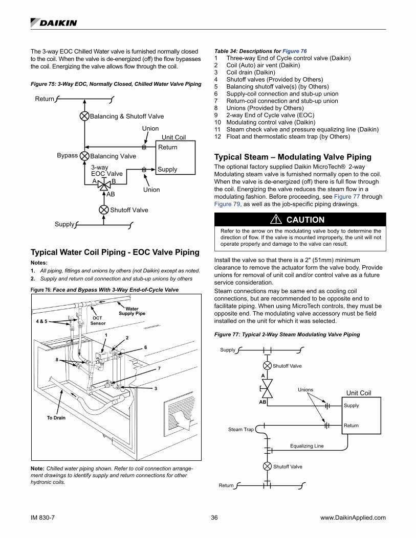
IM 830-7 36 www.DaikinApplied.com
The 3-way EOC Chilled Water valve is furnished normally closed to the coil. When the valve is de-energized (off) the flow bypasses the coil. Energizing the valve allows flow through the coil.
Figure 75: 3-Way EOC, Normally Closed, Chilled Water Valve Piping
Union
3-wayEOC Valve
Shutoff Valve
Balancing & Shutoff Valve
Unit CoilReturn
Supply
Return
Supply
A B
Union
AB
Balancing ValveBypass
Typical Water Coil Piping - EOC Valve PipingNotes:1. All piping, fittings and unions by others (not Daikin) except as noted.2. Supply and return coil connection and stub-up unions by others
Figure 76: Face and Bypass With 3-Way End-of-Cycle Valve
Note: Chilled water piping shown. Refer to coil connection arrange-ment drawings to identify supply and return connections for other hydronic coils.
Table 34: Descriptions for Figure 761 Three-way End of Cycle control valve (Daikin)2 Coil (Auto) air vent (Daikin)3 Coil drain (Daikin)4 Shutoff valves (Provided by Others)5 Balancing shutoff valve(s) (by Others)6 Supply-coil connection and stub-up union7 Return-coil connection and stub-up union8 Unions (Provided by Others)9 2-way End of Cycle valve (EOC)10 Modulating control valve (Daikin)11 Steam check valve and pressure equalizing line (Daikin)12 Float and thermostatic steam trap (by Others)
Typical Steam – Modulating Valve PipingThe optional factory supplied Daikin MicroTech® 2-way Modulating steam valve is furnished normally open to the coil. When the valve is de-energized (off) there is full flow through the coil. Energizing the valve reduces the steam flow in a modulating fashion. Before proceeding, see Figure 77 through Figure 79, as well as the job-specific piping drawings.
CAUTION!Refer to the arrow on the modulating valve body to determine the direction of flow. If the valve is mounted improperly, the unit will not operate properly and damage to the valve can result.
Install the valve so that there is a 2" (51mm) minimum clearance to remove the actuator form the valve body. Provide unions for removal of unit coil and/or control valve as a future service consideration. Steam connections may be same end as cooling coil connections, but are recommended to be opposite end to facilitate piping. When using MicroTech controls, they must be opposite end. The modulating valve accessory must be field installed on the unit for which it was selected.
Figure 77: Typical 2-Way Steam Modulating Valve Piping
Unit Coil
A
AB
Return
Supply
Unions
Shutoff Valve
Shutoff Valve
Equalizing Line
Return
Supply
Steam Trap
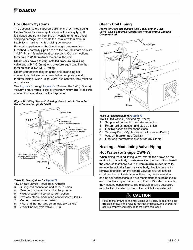
www.DaikinApplied.com 37 IM 830-7
For Steam Systems:The optional factory-supplied Daikin MicroTech Modulating Control Valve for steam applications is the 2-way type. It is shipped separately from the unit ventilator to help avoid shipping damage, yet provide the installer with maximum flexibility in making the field piping connection. For steam applications, the 2-way, angle pattern valve furnished is normally piped open to the coil. All steam coils are 1-1/8" (34mm) female sweat connections. Coil connections terminate 9" (229mm) from the end of the unit.Steam coils have a factory-installed pressure equalizing valve and a 24" (610mm) long pressure equalizing line that terminates in a 1/2" M.P.T. fitting.Steam connections may be same end as cooling coil connections, but are recommended to be opposite end to facilitate piping. When using MicroTech controls, they must be opposite end.See Figure 77 through Figure 79. Connect the 1/4" (6.35mm) vacuum breaker tube to the downstream return line. Make this connection downstream of the trap outlet.
Figure 78: 2-Way Steam Modulating Valve Control - Same End Drain Connection (Coils 68/69)
Table 35: Descriptions for Figure 781&2 Shutoff valves (Provided by Others) 3 Supply-coil connection and stub-up union4 Return-coil connection and stub-up union5 Flexible supply hose swivel connection6 Two-way steam modulating control valve (Daikin)7 Vacuum breaker tube (Daikin)8 Float and thermostatic steam trap (by Others)9 2-way End of Cycle valve (EOC)
Steam Coil PipingFigure 79: Face and Bypass With 2-Way End-of-Cycle Valve - Same End Drain Connection (Piping Within Unit End Compartment)
Table 36: Descriptions for Figure 791&2 Shutoff valves (Provided by Others)3 Supply-coil connection and stub-up union4 Return-coil connection and stub-up union5 Flexible hoses swivel connections6 Two-way End of Cycle steam control valve (Daikin)7 Vacuum breaker tube (Daikin)8 Float and thermostatic steam trap (by Others)
Heating – Modulating Valve PipingHot Water (or 2-pipe CW/HW)When piping the modulating valve, refer to the arrows on the modulating valve body to determine the direction of flow. Install the valve so that there is a 2" (51mm) minimum clearance to remove the actuator form the valve body. Provide unions for removal of unit coil and/or control valve as a future service consideration. Hot water connections may be same end as cooling coil connections, but are recommended to be opposite end to facilitate piping. When using Daikin MicroTech controls, they must be opposite end. The modulating valve accessory must be field installed on the unit for which it was selected.
CAUTION!Refer to the arrows on the modulating valve body to determine the direction of flow. If the valve is mounted improperly, the unit will not operate properly and damage to the valve can result.

IM 830-7 38 www.DaikinApplied.com
2-Way Modulating, Normally Open, Hot Water or 2-pipe CW/HW – TypicalThe 2-way Modulating hot water (or 2-pipe CW/HW) valve is furnished normally open to the coil. When the valve is de-energized (off) there is full flow through the coil. Energizing the valve reduces the volume of water flow in a modulating fashion.
Figure 80: 2-Way Modulating Valve Control, Normally Open, Hot Water or 2-pipe Chilled Water/Hot Water Piping
Unit Coil
AAB
2-Way Modulating
Valve
Return
Supply
Unions
Balancing and Shutoff Valve
Shutoff Valve
Supply
Return
OCT Sensor(2-pipe CW/HW Units Only)
Note: Actuator to be configured for A port to be normally open.
3-Way Modulating, Normally Open, Hot Water or 2-pipe CW/HW – TypicalThe 3-way Modulating hot water (or 2-pipe CW/HW) valve is furnished normally open to the coil. When the valve is de-energized (off) there is full flow through the coil. Energizing the valve allows a varying amount of water to bypass the coil.
Figure 81: 3-Way Modulating Valve Control
Unit Coil
AAB
3-Way Modulating
Valve
Return
Supply
Union
Balancing and Shutoff Valve
Shutoff Valve
Supply
Return
B
Union
Balancing Valve
OCT Sensor(2-pipe CW/HW Units Only)
Note: The A port is always piped to the coil. Actuator to be configured for A port to be Normally Open.
Figure 82: 3-Way Modulating Valve Control (Hot Water Coil Shown)
Table 37: Descriptions for Figure 821 Three-way modulating control valve (Daikin)2 Coil (Auto) air vent (Daikin)3 Coil drain (Daikin)4 Shutoff valves (Provided by Others)5 Balancing shutoff valve(s) (by Others)6 Supply-coil connection and stub-up union7 Return-coil connection and stub-up union8 Flexible hoses swivel connections (Provided by Others)
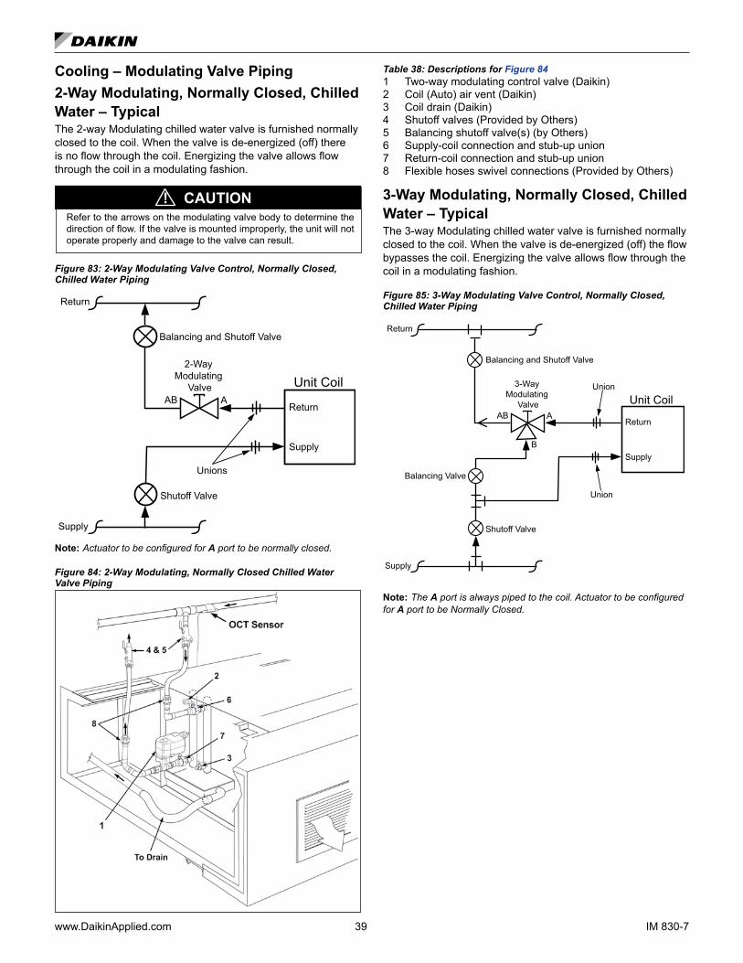
www.DaikinApplied.com 39 IM 830-7
Cooling – Modulating Valve Piping2-Way Modulating, Normally Closed, Chilled Water – TypicalThe 2-way Modulating chilled water valve is furnished normally closed to the coil. When the valve is de-energized (off) there is no flow through the coil. Energizing the valve allows flow through the coil in a modulating fashion.
CAUTION!Refer to the arrows on the modulating valve body to determine the direction of flow. If the valve is mounted improperly, the unit will not operate properly and damage to the valve can result.
Figure 83: 2-Way Modulating Valve Control, Normally Closed, Chilled Water Piping
Unit Coil
AAB
2-Way Modulating
Valve
Return
Supply
Unions
Balancing and Shutoff Valve
Shutoff Valve
Supply
Return
Note: Actuator to be configured for A port to be normally closed.
Figure 84: 2-Way Modulating, Normally Closed Chilled Water Valve Piping
Table 38: Descriptions for Figure 841 Two-way modulating control valve (Daikin)2 Coil (Auto) air vent (Daikin)3 Coil drain (Daikin)4 Shutoff valves (Provided by Others)5 Balancing shutoff valve(s) (by Others)6 Supply-coil connection and stub-up union7 Return-coil connection and stub-up union8 Flexible hoses swivel connections (Provided by Others)
3-Way Modulating, Normally Closed, Chilled Water – TypicalThe 3-way Modulating chilled water valve is furnished normally closed to the coil. When the valve is de-energized (off) the flow bypasses the coil. Energizing the valve allows flow through the coil in a modulating fashion.
Figure 85: 3-Way Modulating Valve Control, Normally Closed, Chilled Water Piping
Unit Coil
AAB
3-Way Modulating
Valve
Return
Supply
Union
Balancing and Shutoff Valve
Shutoff Valve
Supply
Return
B
Union
Balancing Valve
Note: The A port is always piped to the coil. Actuator to be configured for A port to be Normally Closed.
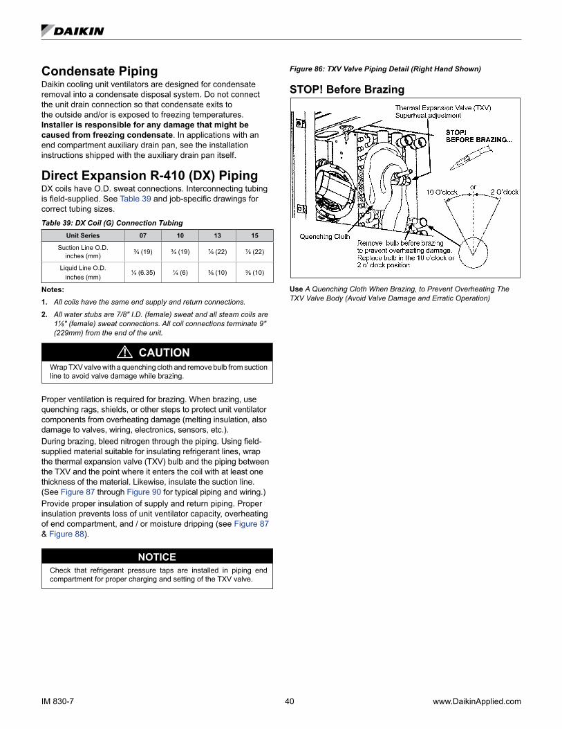
IM 830-7 40 www.DaikinApplied.com
Condensate PipingDaikin cooling unit ventilators are designed for condensate removal into a condensate disposal system. Do not connect the unit drain connection so that condensate exits to the outside and/or is exposed to freezing temperatures. Installer is responsible for any damage that might be caused from freezing condensate. In applications with an end compartment auxiliary drain pan, see the installation instructions shipped with the auxiliary drain pan itself.
Direct Expansion R-410 (DX) PipingDX coils have O.D. sweat connections. Interconnecting tubing is field-supplied. See Table 39 and job-specific drawings for correct tubing sizes.Table 39: DX Coil (G) Connection Tubing
Unit Series 07 10 13 15
Suction Line O.D. inches (mm) ¾ (19) ¾ (19) ⅞ (22) ⅞ (22)
Liquid Line O.D. inches (mm)
¼ (6.35) ¼ (6) ⅜ (10) ⅜ (10)
Notes:1. All coils have the same end supply and return connections. 2. All water stubs are 7/8" I.D. (female) sweat and all steam coils are
1⅛" (female) sweat connections. All coil connections terminate 9" (229mm) from the end of the unit.
CAUTION!Wrap TXV valve with a quenching cloth and remove bulb from suction line to avoid valve damage while brazing.
Proper ventilation is required for brazing. When brazing, use quenching rags, shields, or other steps to protect unit ventilator components from overheating damage (melting insulation, also damage to valves, wiring, electronics, sensors, etc.).During brazing, bleed nitrogen through the piping. Using field-supplied material suitable for insulating refrigerant lines, wrap the thermal expansion valve (TXV) bulb and the piping between the TXV and the point where it enters the coil with at least one thickness of the material. Likewise, insulate the suction line. (See Figure 87 through Figure 90 for typical piping and wiring.) Provide proper insulation of supply and return piping. Proper insulation prevents loss of unit ventilator capacity, overheating of end compartment, and / or moisture dripping (see Figure 87 & Figure 88).
Check that refrigerant pressure taps are installed in piping end compartment for proper charging and setting of the TXV valve.
NOTICE
Figure 86: TXV Valve Piping Detail (Right Hand Shown)
STOP! Before Brazing
Use A Quenching Cloth When Brazing, to Prevent Overheating The TXV Valve Body (Avoid Valve Damage and Erratic Operation)
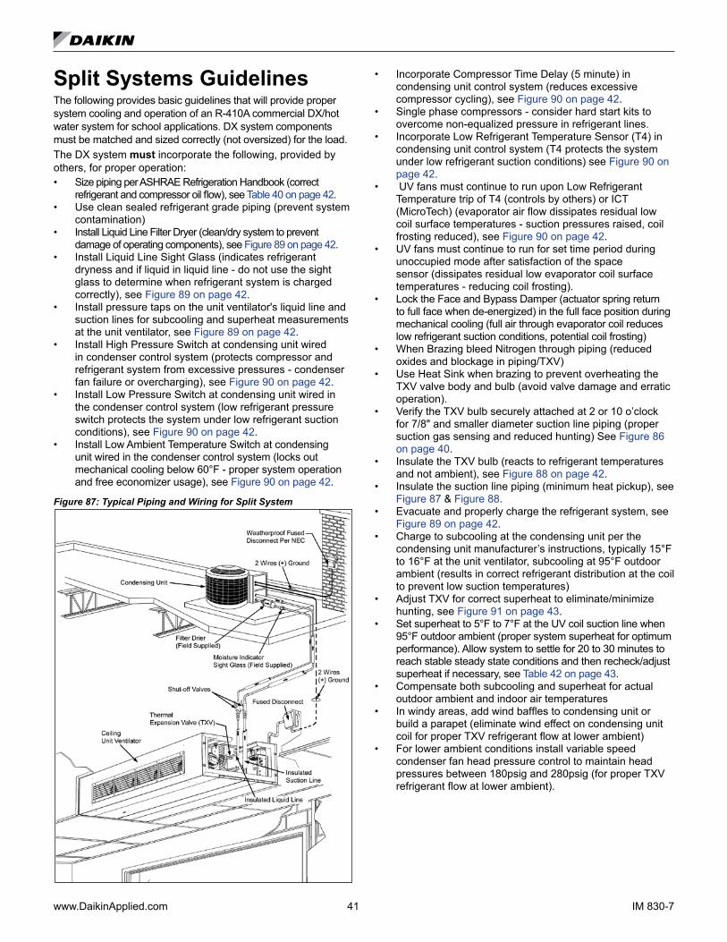
www.DaikinApplied.com 41 IM 830-7
Split Systems GuidelinesThe following provides basic guidelines that will provide proper system cooling and operation of an R-410A commercial DX/hot water system for school applications. DX system components must be matched and sized correctly (not oversized) for the load.The DX system must incorporate the following, provided by others, for proper operation:• Size piping per ASHRAE Refrigeration Handbook (correct
refrigerant and compressor oil flow), see Table 40 on page 42.• Use clean sealed refrigerant grade piping (prevent system
contamination)• Install Liquid Line Filter Dryer (clean/dry system to prevent
damage of operating components), see Figure 89 on page 42.• Install Liquid Line Sight Glass (indicates refrigerant
dryness and if liquid in liquid line - do not use the sight glass to determine when refrigerant system is charged correctly), see Figure 89 on page 42.
• Install pressure taps on the unit ventilator's liquid line and suction lines for subcooling and superheat measurements at the unit ventilator, see Figure 89 on page 42.
• Install High Pressure Switch at condensing unit wired in condenser control system (protects compressor and refrigerant system from excessive pressures - condenser fan failure or overcharging), see Figure 90 on page 42.
• Install Low Pressure Switch at condensing unit wired in the condenser control system (low refrigerant pressure switch protects the system under low refrigerant suction conditions), see Figure 90 on page 42.
• Install Low Ambient Temperature Switch at condensing unit wired in the condenser control system (locks out mechanical cooling below 60°F - proper system operation and free economizer usage), see Figure 90 on page 42.
Figure 87: Typical Piping and Wiring for Split System
• Incorporate Compressor Time Delay (5 minute) in condensing unit control system (reduces excessive compressor cycling), see Figure 90 on page 42.
• Single phase compressors - consider hard start kits to overcome non-equalized pressure in refrigerant lines.
• Incorporate Low Refrigerant Temperature Sensor (T4) in condensing unit control system (T4 protects the system under low refrigerant suction conditions) see Figure 90 on page 42.
• UV fans must continue to run upon Low Refrigerant Temperature trip of T4 (controls by others) or ICT (MicroTech) (evaporator air flow dissipates residual low coil surface temperatures - suction pressures raised, coil frosting reduced), see Figure 90 on page 42.
• UV fans must continue to run for set time period during unoccupied mode after satisfaction of the space sensor (dissipates residual low evaporator coil surface temperatures - reducing coil frosting).
• Lock the Face and Bypass Damper (actuator spring return to full face when de-energized) in the full face position during mechanical cooling (full air through evaporator coil reduces low refrigerant suction conditions, potential coil frosting)
• When Brazing bleed Nitrogen through piping (reduced oxides and blockage in piping/TXV)
• Use Heat Sink when brazing to prevent overheating the TXV valve body and bulb (avoid valve damage and erratic operation).
• Verify the TXV bulb securely attached at 2 or 10 o’clock for 7/8" and smaller diameter suction line piping (proper suction gas sensing and reduced hunting) See Figure 86 on page 40.
• Insulate the TXV bulb (reacts to refrigerant temperatures and not ambient), see Figure 88 on page 42.
• Insulate the suction line piping (minimum heat pickup), see Figure 87 & Figure 88.
• Evacuate and properly charge the refrigerant system, see Figure 89 on page 42.
• Charge to subcooling at the condensing unit per the condensing unit manufacturer’s instructions, typically 15°F to 16°F at the unit ventilator, subcooling at 95°F outdoor ambient (results in correct refrigerant distribution at the coil to prevent low suction temperatures)
• Adjust TXV for correct superheat to eliminate/minimize hunting, see Figure 91 on page 43.
• Set superheat to 5°F to 7°F at the UV coil suction line when 95°F outdoor ambient (proper system superheat for optimum performance). Allow system to settle for 20 to 30 minutes to reach stable steady state conditions and then recheck/adjust superheat if necessary, see Table 42 on page 43.
• Compensate both subcooling and superheat for actual outdoor ambient and indoor air temperatures
• In windy areas, add wind baffles to condensing unit or build a parapet (eliminate wind effect on condensing unit coil for proper TXV refrigerant flow at lower ambient)
• For lower ambient conditions install variable speed condenser fan head pressure control to maintain head pressures between 180psig and 280psig (for proper TXV refrigerant flow at lower ambient).
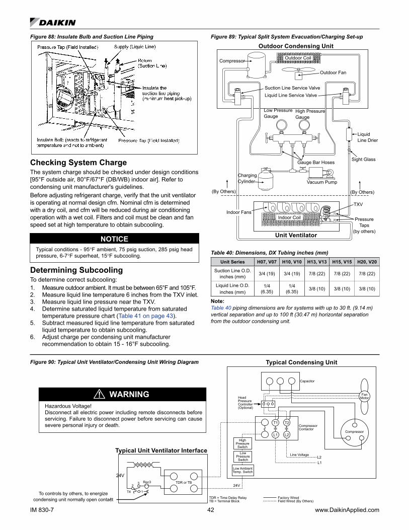
IM 830-7 42 www.DaikinApplied.com
Figure 88: Insulate Bulb and Suction Line Piping
Checking System ChargeThe system charge should be checked under design conditions [95°F outside air, 80°F/67°F (DB/WB) indoor air]. Refer to condensing unit manufacturer's guidelines.Before adjusting refrigerant charge, verify that the unit ventilator is operating at normal design cfm. Nominal cfm is determined with a dry coil, and cfm will be reduced during air conditioning operation with a wet coil. Filters and coil must be clean and fan speed set at high temperature to obtain subcooling.
Typical conditions - 95°F ambient, 75 psig suction, 285 psig head pressure, 6-7°F superheat, 15°F subcooling.
NOTICE
Determining SubcoolingTo determine correct subcooling:1. Measure outdoor ambient. It must be between 65°F and 105°F.2. Measure liquid line temperature 6 inches from the TXV inlet.3. Measure liquid line pressure near the TXV.4. Determine saturated liquid temperature from saturated
temperature pressure chart (Table 41 on page 43).5. Subtract measured liquid line temperature from saturated
liquid temperature to obtain subcooling.6. Adjust charge per condensing unit manufacturer
recommendation to obtain 15 - 16°F subcooling.
Figure 89: Typical Split System Evacuation/Charging Set-up
Liquid Line Drier
Sight Glass
Suction Line Service ValveLiquid Line Service Valve
Outdoor Fan
Compressor
Gauge Bar Hoses
Vacuum Pump
TXV
Indoor Fans
Charging Cylinder
Indoor Coil
Outdoor Coil
Low Pressure Gauge
Outdoor Condensing Unit
Unit Ventilator
High Pressure Gauge
(By Others)(By Others)
Pressure Taps
(by others)
Table 40: Dimensions, DX Tubing inches (mm)Unit Series H07, V07 H10, V10 H13, V13 H15, V15 H20, V20
Suction Line O.D. inches (mm) 3/4 (19) 3/4 (19) 7/8 (22) 7/8 (22) 7/8 (22)
Liquid Line O.D. inches (mm)
1/4 (6.35)
1/4 (6.35) 3/8 (10) 3/8 (10) 3/8 (10)
Note: Table 40 piping dimensions are for systems with up to 30 ft. (9.14 m) vertical separation and up to 100 ft (30.47 m) horizontal separation from the outdoor condensing unit.
Figure 90: Typical Unit Ventilator/Condensing Unit Wiring Diagram
Hazardous Voltage!Disconnect all electric power including remote disconnects before servicing. Failure to disconnect power before servicing can cause severe personal injury or death.
24V
Typical Condensing Unit
WARNING!
To controls by others, to energize condensing unit normally open contact
Typical Unit Ventilator Interface
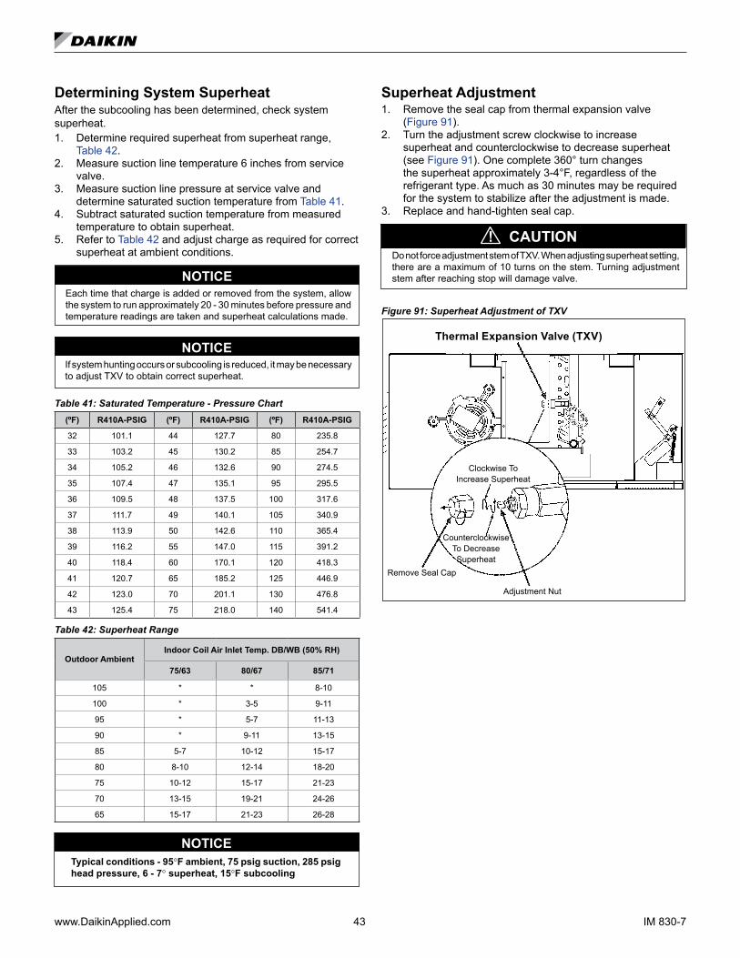
www.DaikinApplied.com 43 IM 830-7
Determining System SuperheatAfter the subcooling has been determined, check system superheat.1. Determine required superheat from superheat range,
Table 42.2. Measure suction line temperature 6 inches from service
valve.3. Measure suction line pressure at service valve and
determine saturated suction temperature from Table 41.4. Subtract saturated suction temperature from measured
temperature to obtain superheat.5. Refer to Table 42 and adjust charge as required for correct
superheat at ambient conditions.
NOTICEEach time that charge is added or removed from the system, allow the system to run approximately 20 - 30 minutes before pressure and temperature readings are taken and superheat calculations made.
NOTICEIf system hunting occurs or subcooling is reduced, it may be necessary to adjust TXV to obtain correct superheat.
Table 41: Saturated Temperature - Pressure Chart(ºF) R410A-PSIG (ºF) R410A-PSIG (ºF) R410A-PSIG
32 101.1 44 127.7 80 235.8
33 103.2 45 130.2 85 254.7
34 105.2 46 132.6 90 274.5
35 107.4 47 135.1 95 295.5
36 109.5 48 137.5 100 317.6
37 111.7 49 140.1 105 340.9
38 113.9 50 142.6 110 365.4
39 116.2 55 147.0 115 391.2
40 118.4 60 170.1 120 418.3
41 120.7 65 185.2 125 446.9
42 123.0 70 201.1 130 476.8
43 125.4 75 218.0 140 541.4
Table 42: Superheat Range
Outdoor AmbientIndoor Coil Air Inlet Temp. DB/WB (50% RH)
75/63 80/67 85/71
105 * * 8-10
100 * 3-5 9-11
95 * 5-7 11-13
90 * 9-11 13-15
85 5-7 10-12 15-17
80 8-10 12-14 18-20
75 10-12 15-17 21-23
70 13-15 19-21 24-26
65 15-17 21-23 26-28
Typical conditions - 95°F ambient, 75 psig suction, 285 psig head pressure, 6 - 7° superheat, 15°F subcooling
NOTICE
Superheat Adjustment1. Remove the seal cap from thermal expansion valve
(Figure 91).2. Turn the adjustment screw clockwise to increase
superheat and counterclockwise to decrease superheat (see Figure 91). One complete 360° turn changes the superheat approximately 3-4°F, regardless of the refrigerant type. As much as 30 minutes may be required for the system to stabilize after the adjustment is made.
3. Replace and hand-tighten seal cap.
CAUTION!Do not force adjustment stem of TXV. When adjusting superheat setting, there are a maximum of 10 turns on the stem. Turning adjustment stem after reaching stop will damage valve.
Figure 91: Superheat Adjustment of TXV
Counterclockwise To Decrease Superheat
Clockwise To Increase Superheat
Remove Seal Cap
Adjustment Nut
Thermal Expansion Valve (TXV)
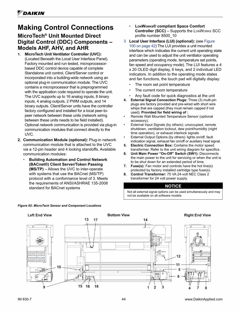
IM 830-7 44 www.DaikinApplied.com
Making Control ConnectionsMicroTech® Unit Mounted Direct Digital Control (DDC) Components – Models AHF, AHV, and AHR 1. MicroTech Unit Ventilator Controller (UVC):
(Located Beneath the Local User Interface Panel). Factory mounted and run tested, microprocessor-based DDC control device capable of complete Standalone unit control, Client/Server control or incorporated into a building-wide network using an optional plug-in communication module. The UVC contains a microprocessor that is preprogrammed with the application code required to operate the unit. The UVC supports up to 16 analog inputs, 8 binary inputs, 4 analog outputs, 2 PWM outputs, and 14 binary outputs. Client/Server units have the controller factory configured and installed for a local peer-to-peer network between these units (network wiring between these units needs to be field installed). Optional network communication is provided via plug-in communication modules that connect directly to the UVC.
2. Communication Module (optional): Plug-in network communication module that is attached to the UVC via a 12-pin header and 4 locking standoffs. Available communication modules:
• Building Automation and Control Network (BACnet®) Client Server/Token Passing (MS/TP) – Allows the UVC to inter-operate with systems that use the BACnet (MS/TP) protocol with a conformance level of 3. Meets the requirements of ANSI/ASHRAE 135-2008 standard for BACnet systems
• lonWorks® compliant Space Comfort Controller (SCC) – Supports the LonWorks SCC profile number 8500_10
3 Local User Interface (LUI) (optional): (see Figure 100 on page 42) The LUI provides a unit mounted interface which indicates the current unit operating state and can be used to adjust the unit ventilator operating parameters (operating mode, temperature set points, fan speed and occupancy mode). The LUI features a 4 x 20 OLED digit display, 6 keys, and 2 individual LED indicators. In addition to the operating mode states and fan functions, the touch pad will digitally display:
• The room set point temperature • The current room temperature • Any fault code for quick diagnostics at the unit4. External Signal Connection Plugs: Three (3) multi-pin
plugs are factory provided and pre-wired with short wire whips that are capped (they must remain capped if not used). Provided for field wiring of :
• Remote Wall Mounted Temperature Sensor (optional accessory).
• External Input Signals (by others): unoccupied, remote shutdown, ventilation lockout, dew point/humidity (night time operation), or exhaust interlock signals
• External Output Options (by others): lights on/off, fault indication signal, exhaust fan on/off or auxiliary heat signal.
5. Electric Connection Box: Contains the motor speed transformer. Refer to the unit wiring diagram for specifics.
6. Unit Main Power “On-Off” Switch (SW1): Disconnects the main power to the unit for servicing or when the unit is to be shut down for an extended period of time.
7. Fuse(s): Fan motor and controls have the hot line(s) protected by factory installed cartridge type fuse(s).
8. Control Transformer: 75 VA 24-volt NEC Class 2 transformer for 24 volt power supply.
Not all external signal options can be used simultaneously and maynot be available on all software models
NOTICE
Figure 92: MicroTech Sensor and Component Locations
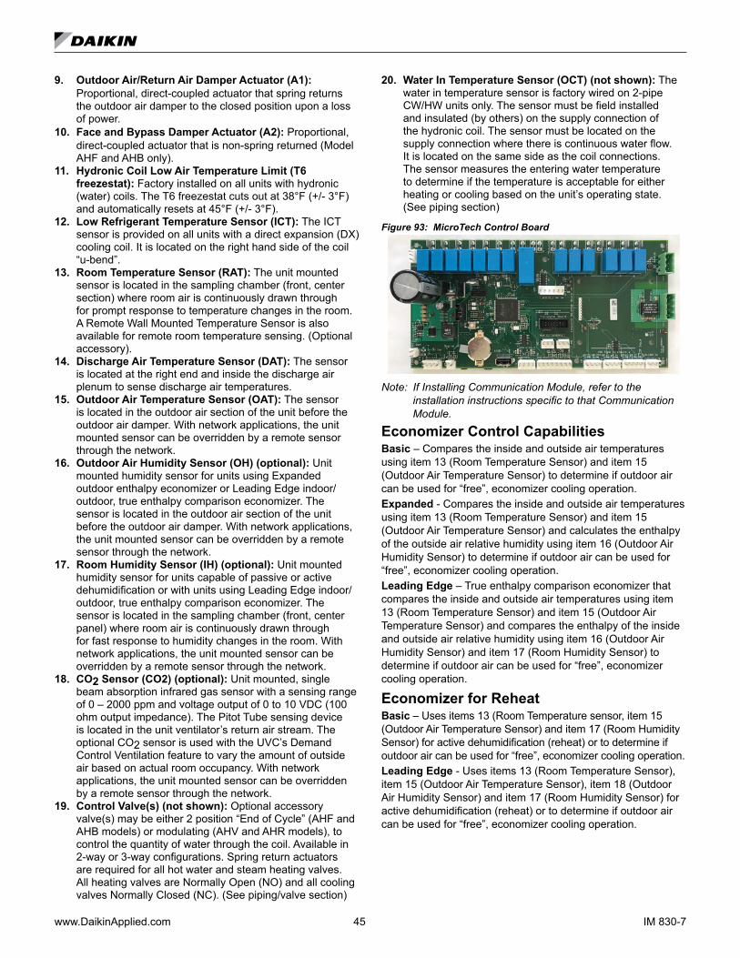
www.DaikinApplied.com 45 IM 830-7
9. Outdoor Air/Return Air Damper Actuator (A1): Proportional, direct-coupled actuator that spring returns the outdoor air damper to the closed position upon a loss of power.
10. Face and Bypass Damper Actuator (A2): Proportional, direct-coupled actuator that is non-spring returned (Model AHF and AHB only).
11. Hydronic Coil Low Air Temperature Limit (T6 freezestat): Factory installed on all units with hydronic (water) coils. The T6 freezestat cuts out at 38°F (+/- 3°F) and automatically resets at 45°F (+/- 3°F).
12. Low Refrigerant Temperature Sensor (ICT): The ICT sensor is provided on all units with a direct expansion (DX) cooling coil. It is located on the right hand side of the coil “u-bend”.
13. Room Temperature Sensor (RAT): The unit mounted sensor is located in the sampling chamber (front, center section) where room air is continuously drawn through for prompt response to temperature changes in the room. A Remote Wall Mounted Temperature Sensor is also available for remote room temperature sensing. (Optional accessory).
14. Discharge Air Temperature Sensor (DAT): The sensor is located at the right end and inside the discharge air plenum to sense discharge air temperatures.
15. Outdoor Air Temperature Sensor (OAT): The sensor is located in the outdoor air section of the unit before the outdoor air damper. With network applications, the unit mounted sensor can be overridden by a remote sensor through the network.
16. Outdoor Air Humidity Sensor (OH) (optional): Unit mounted humidity sensor for units using Expanded outdoor enthalpy economizer or Leading Edge indoor/outdoor, true enthalpy comparison economizer. The sensor is located in the outdoor air section of the unit before the outdoor air damper. With network applications, the unit mounted sensor can be overridden by a remote sensor through the network.
17. Room Humidity Sensor (IH) (optional): Unit mounted humidity sensor for units capable of passive or active dehumidification or with units using Leading Edge indoor/outdoor, true enthalpy comparison economizer. The sensor is located in the sampling chamber (front, center panel) where room air is continuously drawn through for fast response to humidity changes in the room. With network applications, the unit mounted sensor can be overridden by a remote sensor through the network.
18. CO2 Sensor (CO2) (optional): Unit mounted, single beam absorption infrared gas sensor with a sensing range of 0 – 2000 ppm and voltage output of 0 to 10 VDC (100 ohm output impedance). The Pitot Tube sensing device is located in the unit ventilator’s return air stream. The optional CO2 sensor is used with the UVC’s Demand Control Ventilation feature to vary the amount of outside air based on actual room occupancy. With network applications, the unit mounted sensor can be overridden by a remote sensor through the network.
19. Control Valve(s) (not shown): Optional accessory valve(s) may be either 2 position “End of Cycle” (AHF and AHB models) or modulating (AHV and AHR models), to control the quantity of water through the coil. Available in 2-way or 3-way configurations. Spring return actuators are required for all hot water and steam heating valves. All heating valves are Normally Open (NO) and all cooling valves Normally Closed (NC). (See piping/valve section)
20. Water In Temperature Sensor (OCT) (not shown): The water in temperature sensor is factory wired on 2-pipe CW/HW units only. The sensor must be field installed and insulated (by others) on the supply connection of the hydronic coil. The sensor must be located on the supply connection where there is continuous water flow. It is located on the same side as the coil connections. The sensor measures the entering water temperature to determine if the temperature is acceptable for either heating or cooling based on the unit’s operating state. (See piping section)
Figure 93: MicroTech Control Board
Note: If Installing Communication Module, refer to the installation instructions specific to that Communication Module.
Economizer Control CapabilitiesBasic – Compares the inside and outside air temperatures using item 13 (Room Temperature Sensor) and item 15 (Outdoor Air Temperature Sensor) to determine if outdoor air can be used for “free”, economizer cooling operation.Expanded - Compares the inside and outside air temperatures using item 13 (Room Temperature Sensor) and item 15 (Outdoor Air Temperature Sensor) and calculates the enthalpy of the outside air relative humidity using item 16 (Outdoor Air Humidity Sensor) to determine if outdoor air can be used for “free”, economizer cooling operation.Leading Edge – True enthalpy comparison economizer that compares the inside and outside air temperatures using item 13 (Room Temperature Sensor) and item 15 (Outdoor Air Temperature Sensor) and compares the enthalpy of the inside and outside air relative humidity using item 16 (Outdoor Air Humidity Sensor) and item 17 (Room Humidity Sensor) to determine if outdoor air can be used for “free”, economizer cooling operation.
Economizer for ReheatBasic – Uses items 13 (Room Temperature sensor, item 15 (Outdoor Air Temperature Sensor) and item 17 (Room Humidity Sensor) for active dehumidification (reheat) or to determine if outdoor air can be used for “free”, economizer cooling operation.Leading Edge - Uses items 13 (Room Temperature Sensor), item 15 (Outdoor Air Temperature Sensor), item 18 (Outdoor Air Humidity Sensor) and item 17 (Room Humidity Sensor) for active dehumidification (reheat) or to determine if outdoor air can be used for “free”, economizer cooling operation.
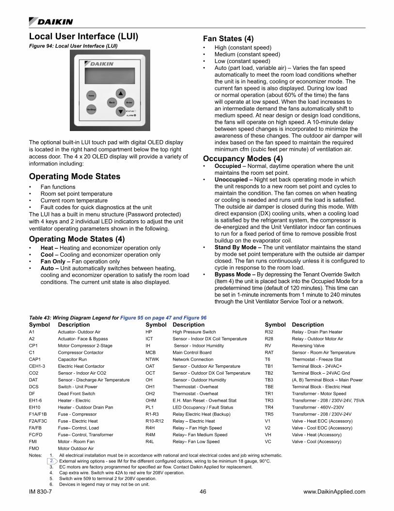
IM 830-7 46 www.DaikinApplied.com
Local User Interface (LUI)Figure 94: Local User Interface (LUI)
The optional built-in LUI touch pad with digital OLED display is located in the right hand compartment below the top right access door. The 4 x 20 OLED display will provide a variety of information including:
Operating Mode States • Fan functions• Room set point temperature• Current room temperature• Fault codes for quick diagnostics at the unitThe LUI has a built in menu structure (Password protected) with 4 keys and 2 individual LED indicators to adjust the unit ventilator operating parameters shown in the following.
Operating Mode States (4)• Heat – Heating and economizer operation only• Cool – Cooling and economizer operation only• Fan Only – Fan operation only• Auto – Unit automatically switches between heating,
cooling and economizer operation to satisfy the room load conditions. The current unit state is also displayed.
Fan States (4)• High (constant speed)• Medium (constant speed)• Low (constant speed)• Auto (part load, variable air) – Varies the fan speed
automatically to meet the room load conditions whether the unit is in heating, cooling or economizer mode. The current fan speed is also displayed. During low load or normal operation (about 60% of the time) the fans will operate at low speed. When the load increases to an intermediate demand the fans automatically shift to medium speed. At near design or design load conditions, the fans will operate on high speed. A 10-minute delay between speed changes is incorporated to minimize the awareness of these changes. The outdoor air damper will index based on the fan speed to maintain the required minimum cfm (cubic feet per minute) of ventilation air.
Occupancy Modes (4)• Occupied – Normal, daytime operation where the unit
maintains the room set point.• Unoccupied – Night set back operating mode in which
the unit responds to a new room set point and cycles to maintain the condition. The fan comes on when heating or cooling is needed and runs until the load is satisfied. The outside air damper is closed during this mode. With direct expansion (DX) cooling units, when a cooling load is satisfied by the refrigerant system, the compressor is de-energized and the Unit Ventilator indoor fan continues to run for a fixed period of time to remove possible frost buildup on the evaporator coil.
• Stand By Mode – The unit ventilator maintains the stand by mode set point temperature with the outside air damper closed. The fan runs continuously unless it is configured to cycle in response to the room load.
• Bypass Mode – By depressing the Tenant Override Switch (Item 4) the unit is placed back into the Occupied Mode for a predetermined time (default of 120 minutes). This time can be set in 1-minute increments from 1 minute to 240 minutes through the Unit Ventilator Service Tool or a network.
Table 43: Wiring Diagram Legend for Figure 95 on page 47 and Figure 96Symbol Description Symbol Description Symbol DescriptionA1 Actuator- Outdoor Air HP High Pressure Switch R32 Relay - Drain Pan Heater A2 Actuator- Face & Bypass ICT Sensor - Indoor DX Coil Temperature R28 Relay - Outdoor Motor Air CP1 Motor Compressor 2-Stage IH Sensor - Indoor Humidity RV Reversing ValveC1 Compressor Contactor MCB Main Control Board RAT Sensor - Room Air TemperatureCAP1 Capacitor Run NTWK Network Connection T6 Thermostat - Freeze StatCEH1-3 Electric Heat Contactor OAT Sensor - Outdoor Air Temperature TB1 Terminal Block - 24VAC+CO2 Sensor - Indoor Air CO2 OCT Sensor - Outdoor DX Coil Temperature TB2 Terminal Block – 24VAC GndDAT Sensor - Discharge Air Temperature OH Sensor - Outdoor Humidity TB3 (A, B) Terminal Block – Main PowerDCS Switch - Unit Power OH1 Thermostat - Overheat TBE Terminal Block - Electric HeatDF Dead Front Switch OH2 Thermostat - Overheat TR1 Transformer - Motor SpeedEH1-6 Heater - Electric OHM E.H. Man Reset - Overheat Stat TR3 Transformer - 208 / 230V-24V, 75VAEH10 Heater - Outdoor Drain Pan PL1 LED Occupancy / Fault Status TR4 Transformer - 460V–230VF1A/F1B Fuse - Compressor R1-R3 Relay Electric Heat (Backup) TR5 Transformer - 208 / 230V-24VF2A/F3C Fuse - Electric Heat R10-R12 Relay – Electric Heat V1 Valve - Heat EOC (Accessory)FA/FB Fuse– Control, Load R4H Relay – Fan High Speed V2 Valve - Cool EOC (Accessory) FC/FD Fuse– Control, Transformer R4M Relay– Fan Medium Speed VH Valve - Heat (Accessory)FMI Motor - Room Fan R4L Relay– Fan Low Speed VC Valve - Cool (Accessory)FMO Motor Outdoor Air Notes: 1. All electrical installation must be in accordance with national and local electrical codes and job wiring schematic.
External wiring options - see IM for the different configured options, wiring to be minimum 18 gauge, 90°C. 3. EC motors are factory programmed for specified air flow. Contact Daikin Applied for replacement. 4. Cap extra wire. Switch wire 42A to red wire for 208V operation. 5. Switch wire 509 to terminal 2 for 208V operation. 6. Devices in legend may or may not be on unit.
2.
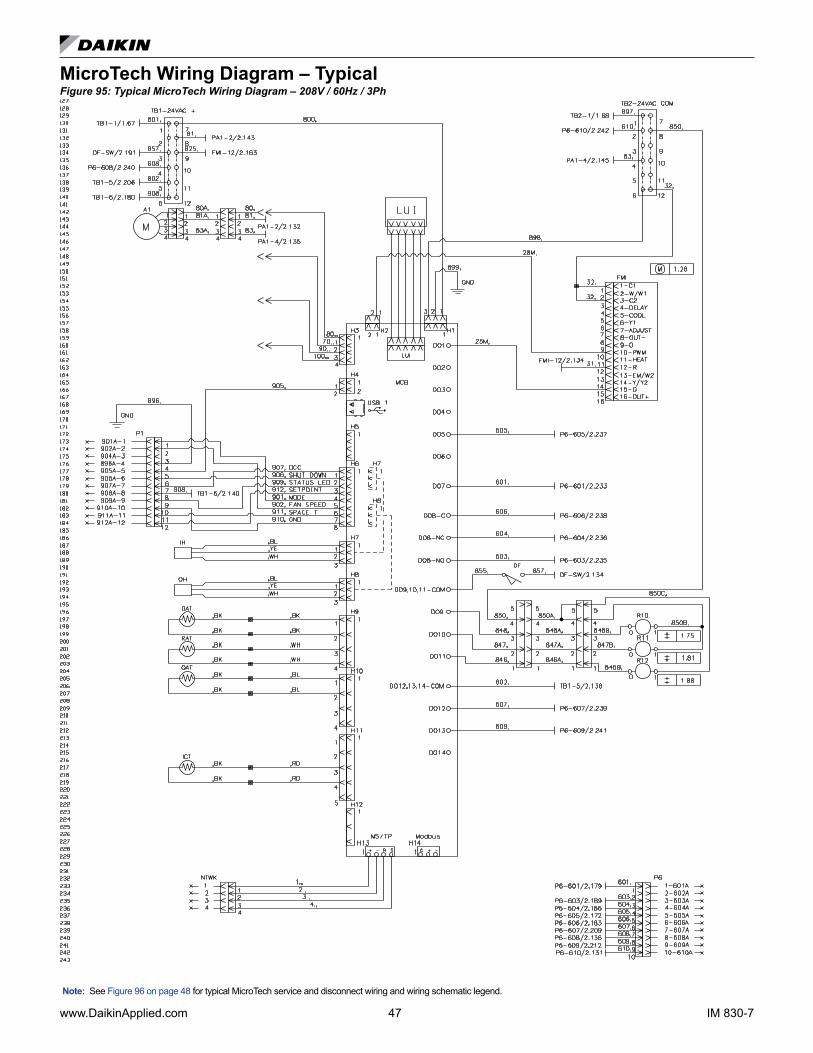
www.DaikinApplied.com 47 IM 830-7
MicroTech Wiring Diagram – TypicalFigure 95: Typical MicroTech Wiring Diagram – 208V / 60Hz / 3Ph
Note: See Figure 96 on page 48 for typical MicroTech service and disconnect wiring and wiring schematic legend.
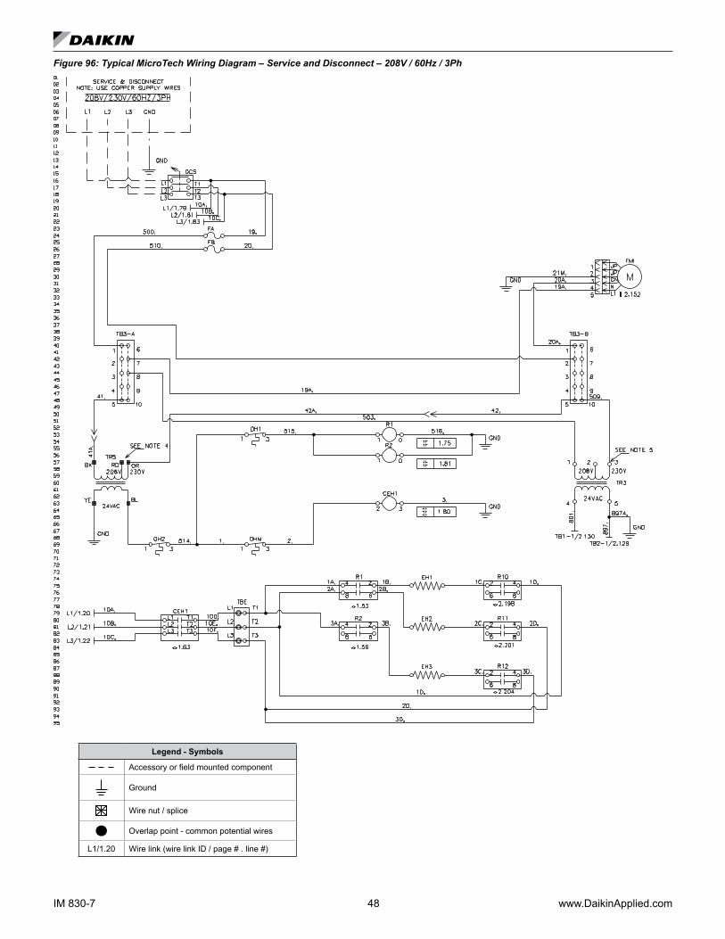
IM 830-7 48 www.DaikinApplied.com
Figure 96: Typical MicroTech Wiring Diagram – Service and Disconnect – 208V / 60Hz / 3Ph
Legend - Symbols
Accessory or field mounted component
Ground
Wire nut / splice
Overlap point - common potential wires
L1/1.20 Wire link (wire link ID / page # . line #)

www.DaikinApplied.com 49 IM 830-7
MicroTech Unit Electrical Connections
WARNING!To avoid electrical shock, personal injury or death, be sure that field wiring complies with local and national fire, safety, and electrical codes, and voltage to the system is within the limits shown in the job-specific drawings and unit electrical data plate(s).
WARNING!Power supply to unit must be disconnected before making field connections. To avoid electrical shock, personal injury or death, be sure to rigorously adhere to field wiring procedures regarding proper lockout and tag out of components.
See Table 48 on page 64 and Figure 95 on page 47 through Figure 98 and the job-specific electrical drawings before proceeding with field power and control wiring. See also the wiring diagram provided on the unit ventilator right front access panel.Unit ventilators equipped with an optional electric heating coil have electric heating coil power connections at right end only.
Procedure1. Provide power supply to right end compartment to match
unit nameplate.
Use copper conductors only. Use of aluminum conductors may result in equipment failure and overheating hazards. All wiring in right hand compartment must be class 1.
CAUTION!
2. Wire leads provided from unit ventilator electric connection box to load side of unit power switch, (switch provided by Daikin).
The junction box has 1"(25mm) and 2"(51mm) knockouts, located 10-1/2"(267mm) from right end of unit.
3. Provide ground wire from grounding screw in switch junction box to switch ground terminal.
4. Wire field power supply to line side of unit power switch. Wire ground conductor to switch ground terminal.
5. Mount unit power switch in switch junction box and install switch cover plate (provided).
6. On units with electric heat, the 2 pole unit power switch is replaced by a 3 pole switch and is mounted in the locations as shown in Figure 115 on page 63. (A) shows switch location for valve control units and (B), and (C) show location for Face & Bypass control units. (B) is for 208, 230 and 265 volt horizontal (AH) units. (C) shows location for 460 volt horizontal (AH) units.
Figure 97: Electric Heat Unit Power Switch Locations
See Electrical Data/Motor Data and Unit Amp without electric heat Table 48 on page 64.
See Electric Heat wiring data Table 49 on page 64.
Figure 98: MicroTech Control DDC Electric Connection Box Located in Right End Compartment (See page 44 for detailed number descriptions)
1 MicroTech Unit Ventilator Controller (UVC)
2 Plug-in Communication Module Location
3 Local User Interface (LUI)
4 External Signal Connection Plugs
5 Electric Connection Box
7 Fuse(s)
8 Control Transformer
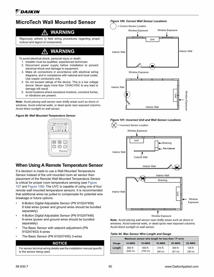
IM 830-7 50 www.DaikinApplied.com
MicroTech Wall Mounted Sensor
WARNINGRigorously adhere to field wiring procedures regarding proper lockout and tagout of components.
WARNINGTo avoid electrical shock, personal injury or death:
1. Installer must be qualified, experienced technician.2. Disconnect power supply before installation to prevent
electrical shock and damage to equipment.3. Make all connections in accordance with electrical wiring
diagrams, and in compliance with national and local codes. Use copper conductors only.
4. Do not exceed ratings of the device. This is a low voltage device: Never apply more than 12VAC/VDC to any lead or damage will result.
5. Avoid locations where excessive moisture, corrosive fumes, or vibrations are present.
Note: Avoid placing wall sensor near drafty areas such as doors or windows. Avoid external walls, or dead spots near exposed columns. Avoid direct sunlight on wall sensor.
Figure 99: Wall Mounted Temperature Sensor
When Using A Remote Temperature SensorIf a decision is made to use a Wall Mounted Temperature Sensor instead of the unit mounted room air sensor then placement of the Remote Wall Mounted Temperature Sensor is critical for proper room temperature sensing (see Figure 107 and Figure 108). The UVC is capable of using one of four remote wall mounted temperature sensors. It is recommended that additional wires be pulled to compensate for potential wire breakage or future options.• 6-Button Digital Adjustable Sensor (PN 910247458)
8 total wires (power and ground wires should be bundled separately)
• 4-Button Digital Adjustable Sensor (PN 910247448) 6-wires (power and ground wires should be bundled separately)
• The Basic Sensor with setpoint adjustment (PN 910247453) 4-wires
• The Basic Sensor (PN 910247450) 3-wires
For sensor terminal wiring details see the installation manual specific to the sensor being used.
NOTICE
Figure 100: Correct Wall Sensor Locations
Window Exposure
Window Exposure
Window
Exposure
Interior Wall
Interior Wall
Interior WallInterior Wall
UnitU
nit
= Correct Sensor LocationWindow Exposure
Figure 101: Incorrect Unit and Wall Sensor Locations
= Incorrect Sensor Location
Window Exposure
Interior Wall
Interior Wall
Window Exposure
Unit
Unit
Interior Wall
Interior Wall
Window Exposure
Cubicle Wall
Shelving
File Cabinet
Shelving
Note: Avoid placing wall sensor near drafty areas such as doors or windows. Avoid external walls, or dead spots near exposed columns. Avoid direct sunlight on wall sensor.
Table 44: Max Sensor Wire Length and GaugeMaximum sensor wire length for less than 1ºF error
Gauge 14 AWG 16 AWG 18 AWG 20 AWG 22 AWG
Length 800 ft. (244 m)
500 ft. (152 m)
310 ft. (94 m)
200 ft. (61 m)
125 ft. (38 m)

www.DaikinApplied.com 51 IM 830-7
Static sensitive components. A static discharge while handling electronic circuit boards can cause damage to the components.Discharge any static electrical charge by touching the bare metal inside the main control panel before performing any service work. Never unplug any cables, circuit board terminal blocks, relay modules, or power plugs while power is applied to the panel.
CAUTION!
Typical Connections For Temperature Sensor ApplicationsThe low voltage field wiring connections have all been centrally located within the unit ventilator and are easily accessible.To simplify field connections, multi-pin plugs are factory provided and pre-wired with short wire whips (Figure 102). Each of the wires in these wire whips is capped and should remain capped if not used. See Table 45 on page 52 for wiring the remote mounted temperature sensor to the unit control wiring. All low voltage field wiring connections must be run in shielded cable with the shield drain wires connected as shown in the field wiring diagrams. For sensor terminal wiring details see the installation manual specific to the sensor being used.Figure 102: Model AV - Field Wiring Whips with Caps Viewed from Right End Compartment
Wire Whips for Field Wiring with Caps (see the wir ing diagram provided on the unit ventilator right front access panel)
Field Wiring at back of Local User Interface (LUI) Panel
Plug for unit mounted sensor
Sensor Functions• Display sensor to show room Temperature, fan speed
(AUTO/HIGH/MEDIUM/LOW), system mode (HEAT/COOL AUTO/OFF), ALARM, Override and occupancy.
MountingLocationAvoid mounting on outside walls or in direct sunlight.
Junction Box, (J-Box)1. Pull the wire through the wall and out of the junction box,
leaving about six inches free.2. Pull the wire through the hole in the base plate.3. Secure the back plate to the box using the #6-32 × 1/2
inch mounting screws provided.
4. Screw the plate firmly to the wall so the foam plate backing is compressed about 50%.
5. Terminate the unit according to the guidelines in the Termination section.
6. Attach Cover by latching it to the top of the base, rotating it down and snapping into place.
7. Secure the cover by backing out the lock-down screws using a 1/16" Allen wrench until it is flush with the bottom of the cover.
Figure 2: Junction box mounting (hardware is provided for both junction box and drywall installation.)
Cover lockdown screws 1/16" allen
Mounting base plate
Drywall Mounting1. Place the base plate against the wall where you want to
mount the sensor.2. Mark out the two mounting holes where the unit will be
attached to the wall. Drill a 3/16" hole in the center of each mounting hole and insert a drywall anchor into the holes.
3. Drill one 1/2" hole in the middle of the marked wiring through hole area.
4. Pull the wire through the wall and out the 1/2" hole, leaving about six inches free.
5. Pull the wire through the hole in the base plate.6. Secure the base to the drywall anchors using the #6 × 1"
mounting screws provided.7. Screw the plate firmly to the wall so the foam plate backing
is compressed about 50%.8. Terminate the unit according to the guidelines in the
Termination section.9. Attach cover by latching it to the top of the base, rotating it
down and snapping it into place.10. Secure the cover by backing out the lock-down screws
using a 1/16" Allen wrench until it is flush with the sides of the cover.
Note: in any wall-mount application, the wall temperature and the temperature of the air within the wall cavity can cause erroneous readings.
The mixing of room air and air from within the wall cavity can lead to condensation, erroneous readings and sensor failure. To prevent these conditions, Daikin recommends sealing the conduit leading to the junction box with fiberglass.

IM 830-7 52 www.DaikinApplied.com
MaintenanceWipe the display as needed with a damp water only cotton cloth. Do not use any type of cleaner as it may damage the buttons or scratch the display. Do not paint.
TerminationsDaikin Applied recommends using shielded 22AWG for all connections and a separate twisted pair for the power wire connections. The shield should be earth grounded only at the power source. Larger gauge wire may be required for runs greater than 250'.
Figure 3: Sensor Circuit Board
CAUTIONThe AC power wiring at terminals [R] & [5] should be run in a separate twisted shielded pair to avoid fluctuating and inaccurate signal levels induced into the other sensor signal wires. This sensor AC power can be run in the same conduit with the sensor signal wire as long as it’s run in twisted, shielded pair and terminated properly.
All wiring must comply with the National Electric Code (NEC) and local codes. Do NOT run any of this device’s wiring in the same conduit as other AC power wiring. Tests show that fluctu-ating and inaccurate signal levels are possible when AC power wiring is present in the same conduit as the signal lines. If you are experiencing any of these difficulties, please contact your Daikin representative.
Table 45: Unit Ventilator MicroTech board to room temperature sensor wiringMicroTech Base Board
Terminal Block Label TB1 H6-1 H6-2 H6-3 H6-4 H6-5 H6-6 H6-7 H6-8
Sensor 910247458
Sensor 910247448
Sensor 910247453
Sensor 910247450
Description 24VAC Occupancy Shutdown(Not Used) Status LED Setpoint Unit Mode Fan Speed 10K RTD Ground
Wire 908 907 906 909 912 901 902 911 910
Typical Wiring
Terminal Label R U 1 (ST) 3 (SP) 2 (FM) 6 (FC) 4 (UTS) 5 (GND)
Description 24VAC Unoccupied Unit Status Output Setpoint Adjust Unit Mode Fan Speed
Room Temp Sensor &
Tenant OverrideGround
Room Temperature Sensor Terminal Designations = Active Terminal = Not Used

www.DaikinApplied.com 53 IM 830-7
Making Control ConnectionsDigital Ready™ – Face & Bypass Control Components Model AHF Digital Ready is a factory installed pre-wired package of selected Direct Digital Control (DDC) components. It facilitates the field hook up of a DDC Unit Ventilator Controller (UVC) that is compatible with these factory installed, pre-wired components, and capable of providing the standard ASHRAE II cycle.
CAUTION!It is the responsibility of the Automatic Temperature Control supplier to confirm that the controls operate correctly and protect the unit.
Digital Ready consists of the following components which are factory wired and powered:
1. Unit Main Power "On-Off" switch: disconnects main power to the unit for service. Non-fused power interrupt switch
2. Fuse(s): fan motor, auto transformer and control transformer have the hot line(s) protected by factory installed cartridge type fuse(s).
3. Three (3) speed HIGH-MEDIUM-LOW-OFF motor fan speed switch (on units with 3-speed EC Motors). Units with Variable EC Motor will not have a speed switch.
4. 75 VA 24-volt NEC Class 2 transformer: for 24-volt power supply
5. Three 10-pole Europa type 16 awg terminal strips: rated for 10 amps at 300 volts with nickel plated connectors and zinc plated clamping screws (TB1, TB2, TB3).
6. Space available in left end compartment: approximately 8" x 21" (203mm x 533mm) for UVC mounting (by others)
Wired to the Terminal Strips:7. Interface with the fan motor start/stop relay (R4): on
units with 3-speed fan. Units with a Variable Speed ECM will have a 0-10vdc terminal interface.
8. Interface with a factory installed Low Air Temperature Limit (T6 - Freezestat): cuts out below 38°F±2 °F and automatically resets above 45°F±2 ºF. Responds when any 15% of the capillary length senses these temperatures. Wired so that upon (T6) cut out, the outside air damper (A1) closes, the hot water valve opens and the 24 volt power supply to the terminal strip (T6 Sig) is interrupted.
9. Discharge Air Temperature Sensors (S2): 10 K ohm NTC (Negative Temperature Coefficient) and 1 K ohm PTC (Positive Temperature Coefficient). Located on the second fan housing from the right to sense discharge air temperatures.
10. Room Temperature Sensors (S1): 10K ohm (NTC) and 1 K ohm (PTC). The unit mounted sensors are located in the unit sampling chamber (bottom panel with perforations), where room air is constantly drawn through for prompt response to temperature changes in the room.
11. Outdoor Air Temperature Sensors (S3): 10K ohm (NTC) and 1 K ohm (PTC). The sensors are located in the outdoor air section of the unit before the outdoor air damper.
12. Outdoor Air/Return Air Damper Actuator (A1): direct coupled, proportional control (2 to 10 VDC or 4 to 20 mA) (spring return).
13. Face and Bypass Damper Actuator (A3): direct coupled, proportional control (2 to 10 VDC or 4 to 20 mA) (non-spring returned).
14. End of Cycle DDC valves (not shown): (by others) with spring return actuators. Interface from the terminal board with one or two providing 24-volt power. Open/shut signal from UVC (by others).
15. 24-volt power wiring harness (not shown): from the right to left-hand end compartment through the built-in metal wire raceway terminating at three terminal blocks.
16. Low Refrigerant Temperature Sensor (T4) (not shown): T4 capillary sensor helps protect against abnormally low evaporator coil temperatures. Direct Expansion (DX) units only.
Figure 103: Component Locations (Horizontal Ceiling Unit Shown)
Bottom ViewLeft End View Right End View
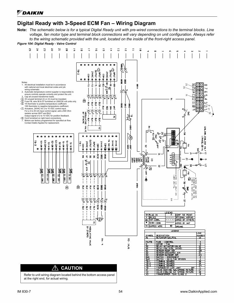
IM 830-7 54 www.DaikinApplied.com
Digital Ready with 3-Speed ECM Fan – Wiring DiagramNote: The schematic below is for a typical Digital Ready unit with pre-wired connections to the terminal blocks. Line
voltage, fan motor type and terminal block connections will vary depending on unit configuration. Always refer to the wiring schematic provided with the unit, located on the inside of the front-right access panel.
Figure 104: Digital Ready - Valve Control
Notes:1. All electrical installation must be in accordance with national and local electrical codes and job wiring schematic.2. Automatic temperature control supplier is responsible to ensure controls operate correctly and protect the unit.3. Cap all unused transformer leads.4. X3 unused terminal (2) or (3) must be insulated.5. Fuse FB, wire 56 & 57 furnished on 208/230 volt units only.6. 1K thermistor is positive temperature coefficient. 10K thermistor is negative temperature coefficient.7. Actuators, 24VAC for 2 to 10 VDC control input. For a 4 to 20 mA input control signal, add a 500 Ohm resistor across WHT and BLK. Output signal of 2 to 10 VDC for position feedback.8. Cord furnished on right hand connections.7. Motors are factory programmed for specified air flow. Contact Daikin Applied for replacement.
Refer to unit wiring diagram located behind the bottom access panel at the right end, for actual wiring.
CAUTION!

www.DaikinApplied.com 55 IM 830-7
Digital Ready – Damper Actuator SpecificationsOutdoor Air/Return Air Damper ActuatorThe outdoor air/return air damper actuator is a unit mounted, direct coupled, proportional control actuator that spring returns the outdoor air damper shut upon a loss of power. The actuator provides proportional damper control based on a 2 to 10 VDC input from the DDC Unit Ventilator Controller (UVC). A 4 to 20 mA input signal can be used with the field addition of a Belimo ZG-R01 (or equivalent) 500 ohm resistor (by others). Refer to the wiring diagram for proper installation of the resistor. A 2 to 10 VDC output signal is provided for damper position feedback. Refer to the wiring diagram for proper installation of the resistor. Rotation is clockwise to open OA, close RA.
Face and Bypass Damper ActuatorThe Face & Bypass damper actuator is a unit mounted, direct coupled, non-spring returned actuator used for the modulation of the face and bypass damper. The actuator provides proportional damper control based on a 2 to 10 VDC input from the DDC Unit Ventilator Controller (UVC). A 4 to 20 mA input signal can be used with the field addition of a Belimo ZG-R01 (or equivalent) 500 ohm resistor (by others). Refer to the wiring diagram for proper installation of the resistor. A 2 to 10 VDC output signal is provided for damper position feedback. Refer to the wiring diagram for proper installation of the resistor. The gears can be manually disengaged with a button on the actuator cover. Rotation is counter-clockwise to bypass air around coil.Figure 105: Outdoor Air/Return Air Damper Actuator & Face and Bypass Damper Actuator
Return Air Damper Actuator
Digital Ready – Unit MountedTemperature Sensor SpecificationsA 10 K ohm Negative Temperature Coefficient (NTC) sensor and a 1 K ohm Positive Temperature Coefficient sensor is provided for the discharge air, outdoor air and room air temperature measurement. They are located next to each other in the air stream as shown in Figure 103 on page 53. Each is wired to the terminal strip separately so that the Automatic Temperature Control contractor may select the appropriate sensor for the application.
10 K ohm NTC SensorThe 10 K ohm NTC sensor is constructed from stainless steel with an epoxy seal and twisted wire leads.
Type: 10K ohm @ 25°CAccuracy: ±0.2°F, 40°F - 80°F ±0.36°F, 32°F - 158°F1 K ohm PTC SensorThe 1 K ohm sensor is a shrink-wrap encapsulated, PTC silicon sensing element with stranded, tinned copper wire leads (#22 AWG).
Type: 1035 ohm @ 25°CAccuracy: ±0.9°F, 5°F - 167°F
Table 46: Temperature Sensors Resistance Values
10 K ohm (NTC)
Temperature (°C) -40 -20 0 20 25 30 40 50 60
Resistance (ohms) 337200 97130 32660 12490 10000 8056 5326 3602 2489
1 K ohm (PTC)
Temperature (°C) -40 -20 0 20 25 30 40 50 60
Resistance (ohms) 613 727 855 997 1035 1074 1153 1237 1323
Table 47: Actuators Technical Data
Actuator Type Power SupplyPower
Consumption Transformer Sizing Torque Running Time Direction of Rotation
Outdoor Air/Return Air Damper
Actuator
24 VAC ±20%
50/60 HZ
24 VDC ±10%
2 Watts4 VA
(class 2 power source)35 in.-lb.
80 to 110 sec. for 0 to 35 in.-lb.
Reversible with built in switch L/R
L = CW with an increase in voltage.
R = CCW with an increase in voltage.
Face & BypassDamper Actuator
24 VAC ±20% 50/60 HZ
24 VDC ±10%
Running: 2.5 Watt;
Holding: 1 Watt
5 VA
(class 2 power source)35 in.-lb.
90 sec. constant (independent of
load)
Spring: reversible with CW/CCW mounting
Motor: reversible with built in switch.
CW = CW with a decrease in signal.
CCW = CCW with a decrease in signal.
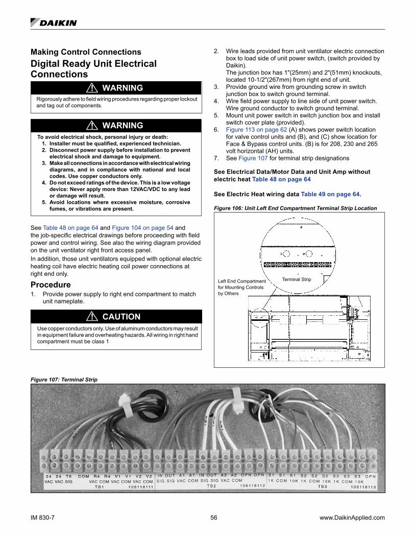
IM 830-7 56 www.DaikinApplied.com
Making Control ConnectionsDigital Ready Unit Electrical Connections
Rigorously adhere to field wiring procedures regarding proper lockout and tag out of components.
WARNING!
To avoid electrical shock, personal injury or death:1. Installer must be qualified, experienced technician.2. Disconnect power supply before installation to prevent
electrical shock and damage to equipment.3. Make all connections in accordance with electrical wiring
diagrams, and in compliance with national and local codes. Use copper conductors only.
4. Do not exceed ratings of the device. This is a low voltage device: Never apply more than 12VAC/VDC to any lead or damage will result.
5. Avoid locations where excessive moisture, corrosive fumes, or vibrations are present.
WARNING!
See Table 48 on page 64 and Figure 104 on page 54 and the job-specific electrical drawings before proceeding with field power and control wiring. See also the wiring diagram provided on the unit ventilator right front access panel.In addition, those unit ventilators equipped with optional electric heating coil have electric heating coil power connections at right end only.
Procedure1. Provide power supply to right end compartment to match
unit nameplate.
Use copper conductors only. Use of aluminum conductors may result in equipment failure and overheating hazards. All wiring in right hand compartment must be class 1
CAUTION!
2. Wire leads provided from unit ventilator electric connection box to load side of unit power switch, (switch provided by Daikin).
The junction box has 1"(25mm) and 2"(51mm) knockouts, located 10-1/2"(267mm) from right end of unit.
3. Provide ground wire from grounding screw in switch junction box to switch ground terminal.
4. Wire field power supply to line side of unit power switch. Wire ground conductor to switch ground terminal.
5. Mount unit power switch in switch junction box and install switch cover plate (provided).
6. Figure 113 on page 62 (A) shows power switch location for valve control units and (B), and (C) show location for Face & Bypass control units. (B) is for 208, 230 and 265 volt horizontal (AH) units.
7. See Figure 107 for terminal strip designations
See Electrical Data/Motor Data and Unit Amp without electric heat Table 48 on page 64
See Electric Heat wiring data Table 49 on page 64.
Figure 106: Unit Left End Compartment Terminal Strip Location
Terminal StripLeft End Compartment for Mounting Controls by Others
Figure 107: Terminal Strip
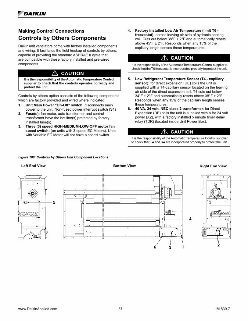
www.DaikinApplied.com 57 IM 830-7
Making Control ConnectionsControls by Others ComponentsDaikin unit ventilators come with factory installed components and wiring. It facilitates the field hookup of controls by others, capable of providing the standard ASHRAE II cycle that are compatible with these factory installed and pre-wired components.
CAUTION!It is the responsibility of the Automatic Temperature Control supplier to check that the controls operates correctly and protect the unit.
Controls by others option consists of the following components which are factory provided and wired where indicated:1. Unit Main Power "On-Off" switch: disconnects main
power to the unit. Non-fused power interrupt switch (S1)2. Fuse(s): fan motor, auto transformer and control
transformer have the hot line(s) protected by factory installed fuse(s).
3. Three (3) speed HIGH-MEDIUM-LOW-OFF motor fan speed switch: (on units with 3-speed EC Motors). Units with Variable EC Motor will not have a speed switch.
4. Factory installed Low Air Temperature (limit T6 - freezestat): across leaving air side of hydronic heating coil. Cuts out below 38°F ± 2°F and automatically resets above 45°F ± 2°F. Responds when any 15% of the capillary length senses these temperatures.
CAUTION!It is the responsibility of the Automatic Temperature Control supplier to check that the T6 freezestat is incorporated properly to protect the unit.
5. Low Refrigerant Temperature Sensor (T4 - capillary sensor): for direct expansion (DE) coils the unit is supplied with a T4-capillary sensor located on the leaving air side of the direct expansion coil. T4 cuts out below 34°F ± 2°F and automatically resets above 38°F ± 2°F. Responds when any 15% of the capillary length senses these temperatures.
6. 40 VA, 24 volt, NEC class 2 transformer: for Direct Expansion (DE) coils the unit is supplied with a for 24 volt power (X2), with a factory installed 5 minute timer delay relay (TDR) (located inside Unit Power Box).
CAUTION!It is the responsibility of the Automatic Temperature Control supplier to check that T4 and R4 are incorporated properly to protect the unit.
Figure 108: Controls by Others Unit Component Locations
Bottom ViewLeft End View Right End View
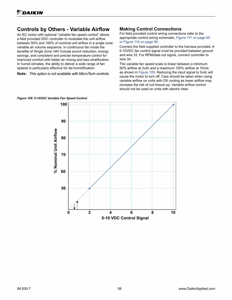
IM 830-7 58 www.DaikinApplied.com
Controls by Others - Variable AirflowAn EC motor with optional “variable fan speed control” allows a field provided DDC controller to modulate the unit airflow between 50% and 100% of nominal unit airflow in a single zone variable air volume sequence. In continuous fan mode the benefits of Single Zone VAV include sound reduction, energy savings, and consistent and precise temperature control for improved comfort with better air mixing and less stratification. In humid climates, the ability to deliver a wide range of fan speeds is particularly effective for de-humidification.
Note: This option is not available with MicroTech controls.
Making Control ConnectionsFor field provided control wiring connections refer to the appropriate control wiring schematic, Figure 111 on page 60 or Figure 110 on page 59.Connect the field supplied controller to the harness provided. A 0-10VDC fan control signal must be provided between ground and wire 33. For RPM/data out signal, connect controller to wire 34. The variable fan speed scale is linear between a minimum 50% airflow at 2vdc and a maximum 100% airflow at 10vdc as shown in Figure 109. Reducing the input signal to 0vdc will cause the motor to turn off. Care should be taken when using variable airflow on units with DX cooling as lower airflow may increase the risk of coil freeze-up. Variable airflow control should not be used on units with electric heat.
Figure 109: 0-10VDC Variable Fan Speed Control
10
100
842 6
50
60
70
80
90
0-10 VDC Control Signal
% N
omin
al U
nit A
irflo
w
0
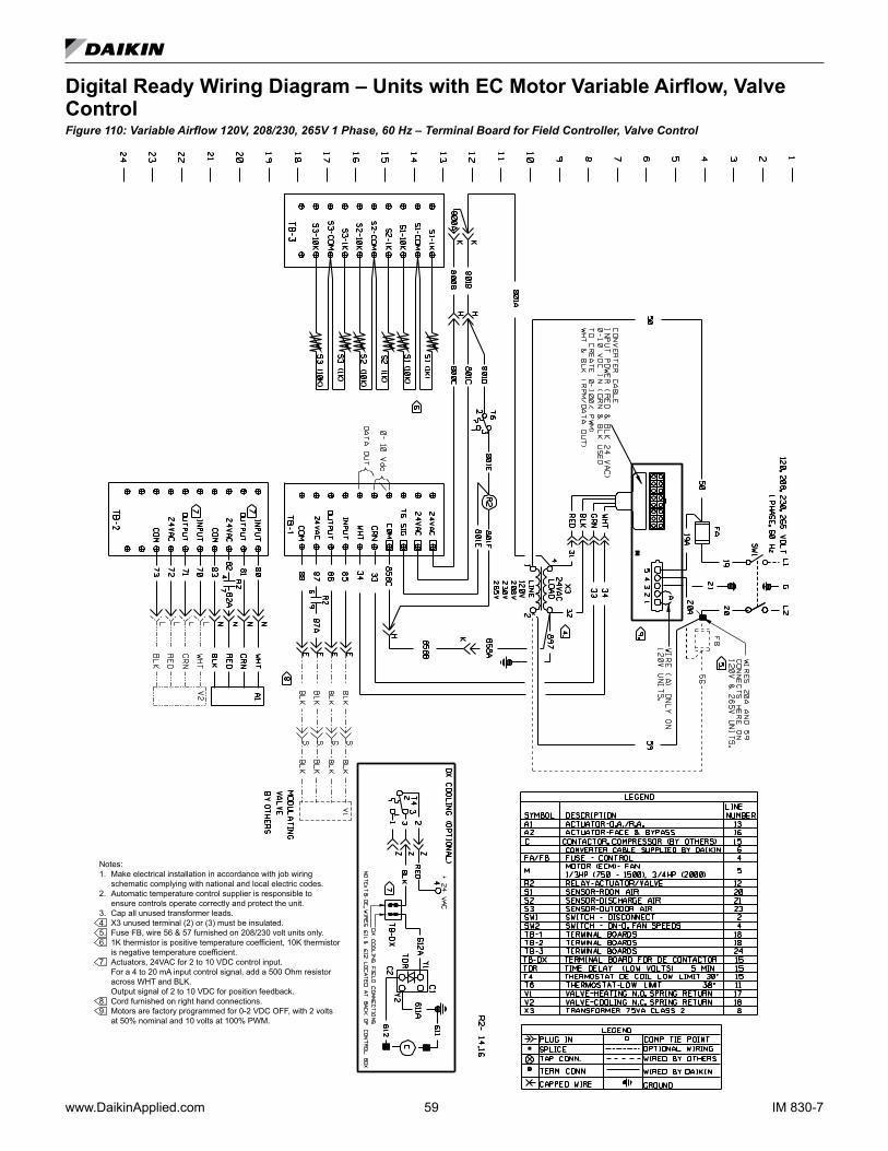
www.DaikinApplied.com 59 IM 830-7
Digital Ready Wiring Diagram – Units with EC Motor Variable Airflow, Valve ControlFigure 110: Variable Airflow 120V, 208/230, 265V 1 Phase, 60 Hz – Terminal Board for Field Controller, Valve Control
Notes:1. Make electrical installation in accordance with job wiring schematic complying with national and local electric codes.2. Automatic temperature control supplier is responsible to ensure controls operate correctly and protect the unit.3. Cap all unused transformer leads.4. X3 unused terminal (2) or (3) must be insulated.5. Fuse FB, wire 56 & 57 furnished on 208/230 volt units only.6. 1K thermistor is positive temperature coefficient, 10K thermistor is negative temperature coefficient.7. Actuators, 24VAC for 2 to 10 VDC control input. For a 4 to 20 mA input control signal, add a 500 Ohm resistor across WHT and BLK. Output signal of 2 to 10 VDC for position feedback.8. Cord furnished on right hand connections.9. Motors are factory programmed for 0-2 VDC OFF, with 2 volts at 50% nominal and 10 volts at 100% PWM.

IM 830-7 60 www.DaikinApplied.com
Typical Controls by Others Wiring Diagram – Units with EC Motor Variable AirflowFigure 111: Variable Airflow 120V and 208/230, 265V 1 Phase, 60 Hz – Motor Switch box, Non-Electric Heat Units
Notes:1. Make electrical installation in accordance with job wiring schematic complying with national and local electric codes.2. Cap all unused transformer leads.3. Fuse FB, & wire 56 furnished on 208/230 volt units only.4. T6, wires 550 & 551 furnished only on units with hot water or chilled water, all others connect transformer wire to wire 501 6. Jumper wire “A” must be connected to pins 1 & 2 for 120V only.7. Automatic temperature control can be wired to TB-DX for DX cooling operation. Typical operation is to wire from the TB-DX to a normally open relay with the relay closing on control call for cooling. For additional information, contact Daikin Applied Applications.8. Motors are factory programmed for specified air flow. Contact Daikin Applied for replacement.
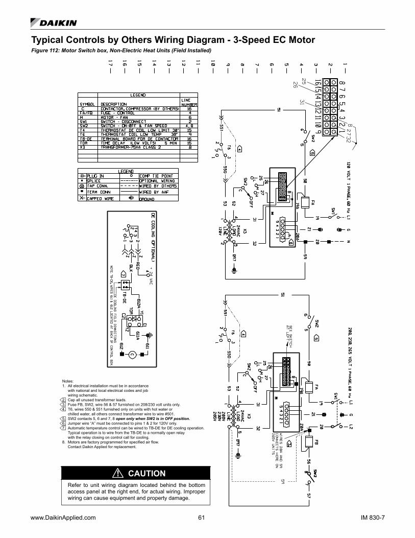
www.DaikinApplied.com 61 IM 830-7
Typical Controls by Others Wiring Diagram - 3-Speed EC MotorFigure 112: Motor Switch box, Non-Electric Heat Units (Field Installed)
Notes: 1. All electrical installation must be in accordance with national and local electrical codes and job wiring schematic.2. Cap all unused transformer leads.3. Fuse FB, SW2, wire 56 & 57 furnished on 208/230 volt units only.4. T6, wires 550 & 551 furnished only on units with hot water or chilled water, all others connect transformer wire to wire #501. 5. SW2 contacts 5, 6 and 7, 8 open only when SW2 is in OFF position.6. Jumper wire “A” must be connected to pins 1 & 2 for 120V only.7. Automatic temperature control can be wired to TB-DE for DE cooling operation. Typical operation is to wire from the TB-DE to a normally open relay with the relay closing on control call for cooling.8. Motors are factory programmed for specified air flow. Contact Daikin Applied for replacement.
Refer to unit wiring diagram located behind the bottom access panel at the right end, for actual wiring. Improper wiring can cause equipment and property damage.
CAUTION!
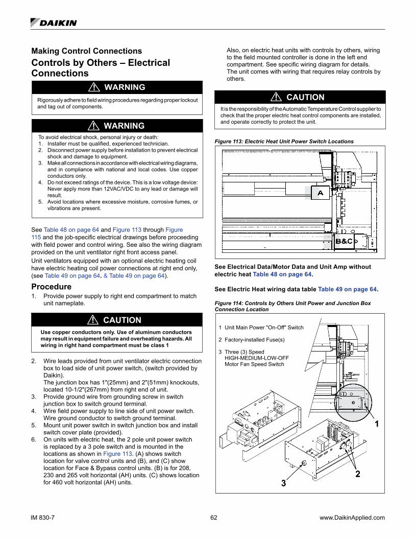
IM 830-7 62 www.DaikinApplied.com
Making Control ConnectionsControls by Others – Electrical Connections
Rigorously adhere to field wiring procedures regarding proper lockout and tag out of components.
To avoid electrical shock, personal injury or death:1. Installer must be qualified, experienced technician.2. Disconnect power supply before installation to prevent electrical
shock and damage to equipment.3. Make all connections in accordance with electrical wiring diagrams,
and in compliance with national and local codes. Use copper conductors only.
4. Do not exceed ratings of the device. This is a low voltage device: Never apply more than 12VAC/VDC to any lead or damage will result.
5. Avoid locations where excessive moisture, corrosive fumes, or vibrations are present.
WARNING!
WARNING!
See Table 48 on page 64 and Figure 113 through Figure 115 and the job-specific electrical drawings before proceeding with field power and control wiring. See also the wiring diagram provided on the unit ventilator right front access panel.Unit ventilators equipped with an optional electric heating coil have electric heating coil power connections at right end only, (see Table 49 on page 64. & Table 49 on page 64).
Procedure1. Provide power supply to right end compartment to match
unit nameplate.
Use copper conductors only. Use of aluminum conductors may result in equipment failure and overheating hazards. All wiring in right hand compartment must be class 1
CAUTION!
2. Wire leads provided from unit ventilator electric connection box to load side of unit power switch, (switch provided by Daikin).
The junction box has 1"(25mm) and 2"(51mm) knockouts, located 10-1/2"(267mm) from right end of unit.
3. Provide ground wire from grounding screw in switch junction box to switch ground terminal.
4. Wire field power supply to line side of unit power switch. Wire ground conductor to switch ground terminal.
5. Mount unit power switch in switch junction box and install switch cover plate (provided).
6. On units with electric heat, the 2 pole unit power switch is replaced by a 3 pole switch and is mounted in the locations as shown in Figure 113. (A) shows switch location for valve control units and (B), and (C) show location for Face & Bypass control units. (B) is for 208, 230 and 265 volt horizontal (AH) units. (C) shows location for 460 volt horizontal (AH) units.
Also, on electric heat units with controls by others, wiring to the field mounted controller is done in the left end compartment. See specific wiring diagram for details.
The unit comes with wiring that requires relay controls by others.
It is the responsibility of the Automatic Temperature Control supplier to check that the proper electric heat control components are installed, and operate correctly to protect the unit.
CAUTION!
Figure 113: Electric Heat Unit Power Switch Locations
See Electrical Data/Motor Data and Unit Amp without electric heat Table 48 on page 64.
See Electric Heat wiring data table Table 49 on page 64.
Figure 114: Controls by Others Unit Power and Junction Box Connection Location
1 Unit Main Power "On-Off" Switch
2 Factory-installed Fuse(s)
3 Three (3) Speed HIGH-MEDIUM-LOW-OFF Motor Fan Speed Switch
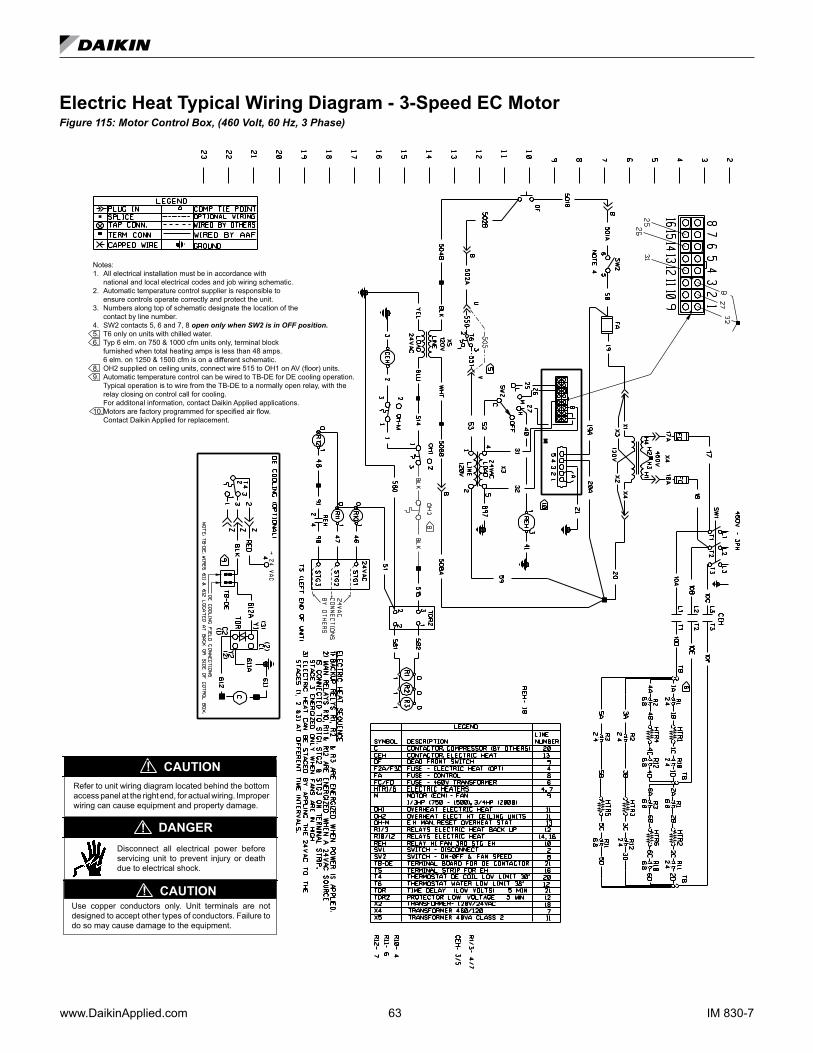
www.DaikinApplied.com 63 IM 830-7
Electric Heat Typical Wiring Diagram - 3-Speed EC MotorFigure 115: Motor Control Box, (460 Volt, 60 Hz, 3 Phase)
Notes:1. All electrical installation must be in accordance with national and local electrical codes and job wiring schematic.2. Automatic temperature control supplier is responsible to ensure controls operate correctly and protect the unit.3. Numbers along top of schematic designate the location of the contact by line number.4. SW2 contacts 5, 6 and 7, 8 open only when SW2 is in OFF position.5. T6 only on units with chilled water. 6. Typ 6 elm. on 750 & 1000 cfm units only, terminal block furnished when total heating amps is less than 48 amps. 6 elm. on 1250 & 1500 cfm is on a different schematic.8. OH2 supplied on ceiling units, connect wire 515 to OH1 on AV (floor) units.9. Automatic temperature control can be wired to TB-DE for DE cooling operation. Typical operation is to wire from the TB-DE to a normally open relay, with the relay closing on control call for cooling. For additonal information, contact Daikin Applied applications.10. Motors are factory programmed for specified air flow. Contact Daikin Applied for replacement.
Refer to unit wiring diagram located behind the bottom access panel at the right end, for actual wiring. Improper wiring can cause equipment and property damage.
CAUTION!
Use copper conductors only. Unit terminals are not designed to accept other types of conductors. Failure to do so may cause damage to the equipment.
CAUTION!
Disconnect all electrical power before servicing unit to prevent injury or death due to electrical shock.
DANGER!

IM 830-7 64 www.DaikinApplied.com
To avoid electrical shock, personal injury or death, be sure that field wiring complies with local and national fire, safety, and electrical codes, and voltage to the system is within the limits shown in the job-specific drawings and unit electrical data plate(s).Power supply to unit must be disconnected when making field connections. Rigorously adhere to field wiring procedures regarding proper lockout and tag out of components.
WARNING!
Table 48: Ceiling - AH Electrical Data/Motor Data and Unit Amp Without Electric Heat
Unit Series
CFM ESP Motor Unit Current Unit MCA Fuse or Breaker
Nominal L/s iwc Pa HP Watts 115V 208V 230V 265V 115V 208V 230V 265V 115V 208V 230V 265V
H07/V07 750 354 0-.45 0-112.5 1/3 246 5.0 3.0 2.8 2.6 6.3 3.8 3.5 3.3 15 15 15 15
H10/V10 1000 472 0-.45 0-112.5 1/3 246 5.0 3.0 2.8 2.6 6.3 3.8 3.5 3.3 15 15 15 15
H13/V13 1250 590 0-.45 0-112.5 1/3 246 5.0 3.0 2.8 2.6 6.3 3.8 3.5 3.3 15 15 15 15
H15/V15 1500 708 0-.45 0-112.5 1/3 246 5.0 3.0 2.8 2.6 6.3 3.8 3.5 3.3 15 15 15 15
H20/V20 2000 944 0-.45 0-112.5 3/4 560 9.6 7.3 6.8 5.5 12.0 9.1 8.5 6.9 20 15 15 15
Notes: Unit wire sizing should be determined in accordance with NEC and local codes.
# Amps at unit voltage, 60 Hz, single phase
Table 49: Standard Motor Electric Heat Capacities, Amps, Wire Sizing, and Over Current Protection
Unit TypeAHF AHV AHR
AHV AHR
AHF AHV AHR
AHV AHR
AHF AHV AHR
AHV AHR
AHF AHV AHR
AHV AHR
AHF AHV AHR
AHV AHR
CFM 750(H07), (V07) 1000(H10), (V10) 1250(H13), (V13) 1500(H15), (V15) 2000(H20), (V20)
Number of Electric Elements 3 6 3 6 3 6 3 6 3 6
kW 6 12 8 16 10 20 12 24 12 24
MBh 20.5 41 27.3 54.6 34.1 68.3 41 81.9 41 81.9
Final Air Temp F (70°F EAT) 95.2 120.3 95.2 120.3 95.2 120.3 95.2 120.3 88.9 107.7
Air Temp Rise 25.2 50.3 25.2 50.3 25.2 50.3 25.2 50.3 18.9 37.7
208-60-1
Electric Heating Amps 28.9 57.7 38.5 76.9 48.1 96.2 57.7 115.4 57.7 115.4
Unit Minimum Circuit Ampacity 39.8 75.9 51.8 99.9 63.9 123.9 75.9 148 81.2 153.4
Max Fuse Size or Circuit Breaker 40 80 60 100 70 125 80 150 90 175
230-60-1
Electric Heating Amps 25 50 33.3 66.7 41.7 83.3 50 100 50 100
Unit Minimum Circuit Ampacity 34.8 66 45.2 86.8 55.6 107.7 66 128.5 71 133.5
Max Fuse Size or Circuit Breaker 35 70 50 90 60 110 70 150 80 150
265-60-1
Electric Heating Amps 21.7 43.3 28.9 57.8 36.1 72.2 43.3 86.6 43.3 86.6
Unit Minimum Circuit Ampacity 30.3 57.4 39.4 75.5 48.4 93.5 57.4 111.6 61 115.2
Max Fuse Size or Circuit Breaker 35 60 40 80 50 100 60 125 70 125
208-60-3
Electric Heating Amps 16.7 33.4 22.2 44.5 27.8 55.6 33.4 66.7 33.4 66.7
Unit Minimum Circuit Ampacity 24.6 45.4 31.5 59.3 38.5 73.2 45.4 87.1 50.8 92.5
Max Fuse Size or Circuit Breaker 25 50 35 60 40 80 50 90 60 100
230-60-3
Electric Heating Amps 14.5 28.9 19.3 38.5 24.1 48.2 28.9 57.8 28.9 57.8
Unit Minimum Circuit Ampacity 21.6 39.6 27.6 51.7 33.6 63.7 39.6 75.8 44.6 80.8
Max Fuse Size or Circuit Breaker 25 40 30 60 35 70 40 80 40 90
460-60-3
Electric Heating Amps 7.2 14.5 9.6 19.3 12 24.1 14.5 28.9 14.5 28.9
Unit Minimum Circuit Ampacity 10.6 19.6 13.6 25.7 16.6 31.7 19.6 37.7 21.1 39.1
Max Fuse Size or Circuit Breaker 15 25 20 30 20 35 25 40 25 40
Note: Electric heat disconnect provided.

www.DaikinApplied.com 65 IM 830-7
Unit Ventilator(s) Start-up
Remove debris, dust, dirt and any obstruction from the outside air ducting, return air ducting (if applicable) and discharge air (if applicable) as this will affect unit performance.
NOTICE
1. Open the bottom-hinged access panels. Before proceeding, inspect the fan system to be sure that
all parts are aligned properly and move freely. Inspect fans and fan discharge area for obstructions. Rotate fans manually. Check that a clean filter is installed and ductwork to and from the unit ventilator is free of debris.
2. All panels should be in place and properly fastened.
Do not attempt to operate the unit fans until the fan bearings have been oiled. Oiled bearings provide smooth, and quiet operation of the fan system.
CAUTION!
Battery BackupThe controller battery protects the time clock schedule in the event of a power loss. This battery should be replaced every 3 years with a new CR2032 or equivalent.
Remove Battery Shipping TabCheck that board backup battery shipping tab is removed. To remove, grasp tab and gently pull. Battery should be replaced every 3 years of unit service.
Remove Battery ShippingTab
Oiling the Fan Shaft End BearingAccess to fan shaft bearing is through bottom hinged access panel, in the units left end compartment (Figure 116). Lift the oiler cap. Oil, using a few drops of high grade SAE 20 or 30 non detergent oil. Periodically oil the bearing every 6-12 months to maintain proper lubrication.Figure 116: Oiling PointNote: Access to the Fan Shaft Bearing Through the Bottom, Large- Hinged Access Panel. The bearing is located at the Left End of the Unit.
Bearing Oiler Cap
For 1500 and 2000 cfm units, access to the fan shaft bearing is through the bottom hinged access panel. It is located between the third and fourth fan housing from the right (Figure 117).
NOTICE
Figure 117: Oiling Point for 1500 and 2000 cfm unitsBearing Oiler Cap
NOTICEG.E. motor manufacturer recommends not oiling the fan motor.
Start-up Procedure1. After the unit ventilator has been properly installed,
activate unit electrical power and applicable chilled water/hot water/steam/refrigerant systems.
2. Using the applicable control, activate the unit ventilator. Depending on the operating mode selected, the dampers, fans, and other components should operate as needed.
3. Run the unit ventilator for ten minutes, listening and observing. Fans should be operating correctly and rotating in proper direction, without unusual noise. Likewise, the unit should be free of sheet metal rattles and / or unusual noises. All panels should be in place and properly fastened. Check for air leaks and condensation.
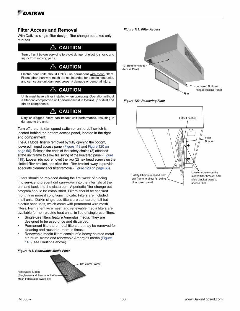
IM 830-7 66 www.DaikinApplied.com
Filter Access and RemovalWith Daikin’s single-filter design, filter change out takes only minutes.
Turn off unit before servicing to avoid danger of electric shock, and injury from moving parts.
CAUTION!
Units must have a filter installed when operating. Operation without a filter can compromise unit performance due to build up of dust and dirt on components.
Dirty or clogged filters can impact unit performance, resulting in damage to the unit.
Electric heat units should ONLY use permanent wire mesh filters. Filters other than wire mesh are not intended for electric heat units, and can cause unit damage, property damage or personal injury.
CAUTION!
CAUTION!
CAUTION!
Turn off the unit, (fan speed switch or unit on/off switch is located behind the bottom access panel, located in the right end compartment).The AH Model filter is removed by fully opening the bottom, louvered hinged access panel (Figure 119 and Figure 120 on page 66). Release the ends of the safety chains (2) attached at the unit frame to allow full swing of the louvered panel (Figure 119). Loosen (do not remove) the two (2) hex head screws on the slotted filter bracket, and slide the –filter bracket away to provide adequate clearance for filter removal (Figure 120 on page 66).
Filters should be replaced during the first week of placing into service to prevent dirt carry-over into the internals of the unit and back into the classroom. A periodic filter change out program should be established. Filters should be checked monthly or more if conditions indicate. Filters are included in all units. Daikin single-use filters are standard on all but electric heat units, which come with permanent wire mesh filters. Permanent wire mesh and renewable media filters are available for non-electric heat units, in lieu of single-use filters.• Single-use filters feature Amerglas media. They are
designed to be used once and discarded.• Permanent filters are metal filters that may be removed for
cleaning and reused numerous times.• Renewable media filters consist of a heavy painted metal
structural frame and renewable Amerglas media (Figure 118) (see Cautions above).
Figure 118: Renewable Media Filter
Renewable Media (Single-use and Permanent Wire Mesh Filters also Available)
Structural Frame
Figure 119: Filter Access
Louvered Bottom-Hinged Access Panel
Filter
12" Bottom-Hinged Access Panel
Figure 120: Removing Filter
Safety Chains released from unit frame to allow full swing of louvered panel
Loosen screws on the slotted filter bracket and slide bracket away to access filter
Filter Bracket
Filter Location
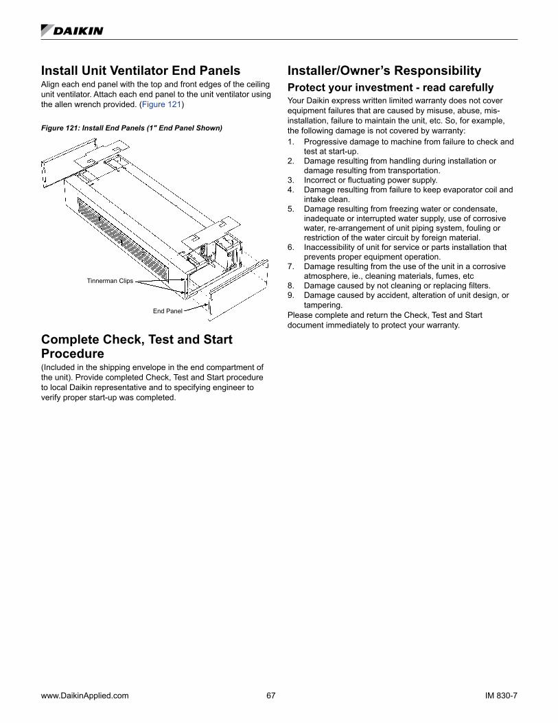
www.DaikinApplied.com 67 IM 830-7
Install Unit Ventilator End PanelsAlign each end panel with the top and front edges of the ceiling unit ventilator. Attach each end panel to the unit ventilator using the allen wrench provided. (Figure 121)
Figure 121: Install End Panels (1" End Panel Shown)
Tinnerman Clips
End Panel
Complete Check, Test and Start Procedure (Included in the shipping envelope in the end compartment of the unit). Provide completed Check, Test and Start procedure to local Daikin representative and to specifying engineer to verify proper start-up was completed.
Installer/Owner’s ResponsibilityProtect your investment - read carefullyYour Daikin express written limited warranty does not cover equipment failures that are caused by misuse, abuse, mis-installation, failure to maintain the unit, etc. So, for example, the following damage is not covered by warranty:1. Progressive damage to machine from failure to check and
test at start-up.2. Damage resulting from handling during installation or
damage resulting from transportation.3. Incorrect or fluctuating power supply.4. Damage resulting from failure to keep evaporator coil and
intake clean.5. Damage resulting from freezing water or condensate,
inadequate or interrupted water supply, use of corrosive water, re-arrangement of unit piping system, fouling or restriction of the water circuit by foreign material.
6. Inaccessibility of unit for service or parts installation that prevents proper equipment operation.
7. Damage resulting from the use of the unit in a corrosive atmosphere, ie., cleaning materials, fumes, etc
8. Damage caused by not cleaning or replacing filters.9. Damage caused by accident, alteration of unit design, or
tampering.Please complete and return the Check, Test and Start document immediately to protect your warranty.
IM 830-7 ©2019 Daikin Applied (8/19) | (800) 432–1342 | www.DaikinApplied.com
Daikin Applied Training and DevelopmentNow that you have made an investment in modern, efficient Daikin equipment, its care should be a high priority. For training information on all Daikin HVAC products, please visit us at www.DaikinApplied.com and click on Training, or call 540-248-9646 and ask for the Training Department.
Warranty
All Daikin equipment is sold pursuant to its standard terms and conditions of sale, including Limited Product Warranty. Consult your local Daikin Applied representative for warranty details. Refer to Form 933-430285Y. To find your local Daikin Applied representative, go to www.DaikinApplied.com.
Aftermarket Services
To find your local parts office, visit www.DaikinApplied.com or call 800-37PARTS (800-377-2787). To find your local service office, visit www.DaikinApplied.com or call 800-432-1342.
This document contains the most current product information as of this printing. For the most up-to-date product information, please go to www.DaikinApplied.com.
Products manufactured in an ISO Certified Facility.