document resume ed 121 587 se 020 457 faller, … · document resume ed 121 587 se 020 457 ......
TRANSCRIPT

DOCUMENT RESUME
ED 121 587 SE 020 457
AUTHOR Faller, Robert G., Ed.; And OthersTITLE Study Modules for Calculus-Based General Physics.
[Includes Modules 27-30: Direct-Current Circuits;Magnetic Forces; Ampere's Lay; and Faraday's Law].
INSTITUTION Nebraska Univ., Lincoln.SPONS AGENCY National Science Foundation, Washington, D.C.PUB DATE 75NOTE 85p.;Prepared at a College Faculty Workshop
(University of Colorado, Boulder, June 23-July 11,1975); Directions for the CBP nodules are found in SE020 448; Related documents are SE 020 449-461
AVAILABLE FROM University of Nebraska, CBP workshop, Behlenlaboratory of Physics, Lincoln, Nebraska 68588(entire set of 42 modules, 315.00)
EDES PRICE MF-$0.83 HC-$4.67 Plus PostageDESCRIPTORS *Calculus; College Science; *Course Descriptions;
Electricity; Higher Education; IndividualizedCurriculum; Individualized Instruction; InstructionalMaterials; Nagnets; *Physics; *Programed Instruction;Science Education; Undergraduate Study
IDENTIFIERS Amperes Law; Faradays Law; Keller Plan; Nagnetism;*Personalized System of Instruction; PSI
ABSTRACTThis is part of a series of 42 Calculus Based Physics
(CBP) modules totaling about 1.00 pages. The nodules include studyguides, practice tests, and mastery tests for a full-yearindividualized course in calculus-based physics based on thePersonalized System of Imstruction (PSI).. The units are not intendedto be used without outside materials; references to specific sectionsin four elementary physics textbooks appear in the modules. Specificmodules included in this document are: Module 27--Direct-CurrentCircuits, Module 28--Magnetic Forces, Module 29--Ampere's Law, andModule 30--Faraday's Law. (CP)
***********************************************************************Documents acquired by 22:C include many informal unpublished
* materials not available from other sources. ERIC sakes every effort ** to obtain the best copy available. Nevertheless, items of marginal ** reproducibility are often encountered and this affects the quality ** of the microfiche and hardcopy reproductions ERIC makes available ** via the 2RIC Document Reproduction 7Service (EDRS). EDRS is not* responsible for the quality of the original document. Reproductions ** supplied by EDRS are the best that can be made from the original. ************************************************************************
1851ZIC
I3
44olgtvth4o.eduatih.
totbhi/1.44.3
ocientiStandotsconew
tV
FUN
DA
ME
NT
AL
S OF
PHY
$ICS
cs2 eletentbri Coma! PlAnit.S
EletneriA
Vy
(lagiCal P
loiptc
universtty Physics
%
SIVT
:6341" SuIDE
S0
4M111.11.11M
p=tt
FRAcnce ecAM5
0
"..m.a.
IFF
QSoPPR
EM
Dram
eceiNles
o
ser or Hi1ar4C
M4 71«trn.
adnlnpmlm
loomm
nryw.....=
..1%...W
..MP
b
14
1141
ik
U
NO
QZ
O

Comsents
These modules were prepared by fifteen college physics professors foruse in self-paced, mastery-oriefted, student-tutored, calculus-basedgeneral physics courses. This style of teaching offers students apersonalized system of instruction (PSI), in which they increasetheir knowledge of physics and experience a positive learning environ-ment. We hope our efforts in preparing these modules will enable youto try and enjoy teaching physics using PSI.
OWN ANDERSONSTEPHEN BAKERVAN BLEUMELFERNAND BRUHSCHWIGDAVID JOSEPHROBERT KARPLUSMICHAEL MOLONEYJACK FIRISEE
GARY NEWSYIVOR NEWSHAMWILLIAM SNOWWILLARD SPERRYROBERT SWANSONJAMES TANNERDAVID ma
Robert G. FullerDirector
College Faculty Workshop
MODULE AUTHORS
Bucknell UniversityRice UniversityWorcester Polytechnic InstituteEmpire State CollegeUniversity of Nebraska - LincolnUniversity of California - BerkeleyRose Huffman Institute of TechnologyCalifornia State University - Long BeachBoise State UniversityOlivet Nazarene CollegeUniversity of Missouri - RollaCentral Washington State CollegeUniversity of California - San DiegoGeorgia Institute of TechnologyKalamazoo.College
These modules were prepared by the module authors at aCollege Faculty Workshop held at the University ofColorado - Boulder, from June 23 to July 11, 1975.
Albert A. BartlettThomas C. CampbellHarold Q Fuller
Workshop Staff
University of ColoradoIllinois Central CollegeUniversity of Missouri - Rolla
Calculus-Based Physics (CBP) Modules Production Staff
Robert G. FullerThomas C. Campbell
William D. SnowCatherine A. Caffrey
EditorAssistant EditorIllustratorProduction Editor
Copyright CBP WorkshopUniversity of Nebraska - Lincoln, 1975
Reproduction Rights Granted
3

=ma TO USERS
In the upper right-hand corner of each Mastery Test you will find the "pass"and "recycle" terms and a rot' of numbers "1 2 3 ..." to facilitate thegrading of the tests. We intend that you indicate the weakness of a studentwho is asked to recycle on the test by putting a circle around the number ofthe learning objective that the student did not satisfy. This procedure willenable you easily to identify the learning objectives that are causing yourstudents difficulty.
comma TO USERS
It is conventional practice to provide several review modules per semester orquarter, as confidence builders, learning opportunities, and to consolidate whathas been learned. You the instructor should write these nodules yourself, in ternsof the particular weaknesses and needs of your students. Thus, we have not suppliedreview nodules as such with the CBE Modules. However, fifteen sample review testswere written during the Workshop and are available for your use as guides. Pleasesend $1.00 to CBE Modules, Behlen Lab of Physics, University of Nebraska - Lincoln,Nebraska 68588.
FINIS
This printing has completed the initial CBP project. We hope that you are findingthe materials helpful in your teaching. Revision of the modules is being planned
for the Summer of 2976. We therefore solicit your comments, suggestions, and /or
corrections for the revised edition. Please write or call
Phone (402) 472-2790(402) 472-2742
CBP WORKSHOPBehlen Laboratory of PhysicsUniversity of NebraskaLincoln, NE 68588
4

Module
STUDY GUIDE
DIRECT-CURRENT CIRCUITS
1
A
INTRODUCTION
One way to help you understand a new phenomenon is to show you that it is like
something that you are already familiar with. This method is used very frequently
in physics, e.g., the electric field is like the gravitational field. This module
will introduce you to a simple class of RC circuits in which there are currents,
charges, and voltages that decay exponentially. This may be your first detailed
study of exponential decay, but it is like (analagous to) radioactive decay,
Newton's law of cooling, the final depletion of a natural resource, the decrease
in atmospheric pressure with altitude, and some other interesting phenomena.
With a sign change, it is like a simple model of exponential growth, which is
how ;opulation, energy consumption, and pollution generation seem to be growing.
The module begins, however, with a few simple ideas applied to direct-current
circuits. These are the basic ideas upon which you will later build an under-
standing of alternating-current circuits. This course will not cover electronics,
but it will provide some of the introductory concepts that are needed for a study
of electronic devices and circuits.
PREREQUISITES
Before you begin this nodule, Location ofyou should be able to Prerequisite Content
*Apply Ohm's law to find potential difference from Ohm's Lawcurrent and resistance (needed for Objective 1 of Modulethis module)
*Find potential difference of a capacitor from Capacitorscharge and capacitance (needed for Objective 4 of Modulethis module)
*Find the power developed in a resistor (needed for Ohm's LawObjective 1 of this module) Module
STUDY GUIDE: Direct-Current Circuits 2
LEARNIUG OBJECTIVES
After you have mastered the content of this nodule, you will be able to:
1. Loop equation - Analyze a single-loop direct-current (dc) circuit consisting
of resistances and a seat of emf w find the loop current, the power developed
in the circuit elements, and the terminal potential difference of the seat of
emf.
2. Equivalent resistance - Determine an equivalent resistance for a series or
parallel combination of resistances.
3. RC -loop equation - Write the differential equation for a single RC loop, and
verify that particular assumed solutions satisfy this equation.
4. Exponential decay - Write the equation for the current, charge or voltage
of a capacitor as a function of time in a single RC loop, and manipulate this
equation to determine the value of one of the parameters when an appropriate
set of other values is given.
6
STUDY GUIDE: Direct-Current Circuits 3(6 1)
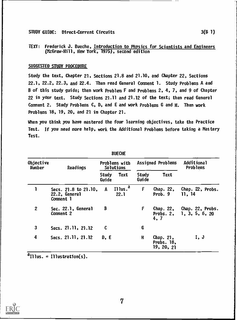
TEXT: Frederick J. Bueche, Introduction to Physics for Scientists and Engineers(McGraw-Hill, New York, 1975), second edition
SUGGESTED STUDY PROCEDURE
Study the text, Chapter 21, Sections 21.8 and 21.10, and Chapter 22, Sections
22.1, 22.2, 22.3, and 22.4. Then read General Comment 1. Study Problems A and
B of this study guide; then work Problem F and Problems 2, 4, 7, and 9 of Chapter
22 in your text. Study Sections 21.11 and 21.12 of the text; then read General
Comment 2. Study Problems C, D, and E and work Problems G and H. Then work
Problems 18, 19, 20, and 21 in Chapter 21.
When you think you have mastered the four learning objectives, take the Practice
Test. If you need more help, work the Additional Problems before taking a Mastery
Test.
BUECHE
Objective Problems with Assigned Problems AdditionalNumber Readings Solutions Problems
Study Text Study TextGuide Guide
1 Secs. 21.8 to 21.10, A Illus.a F Chap. 22, Chap. 22, Probs.
22.2, General 22.1 Prob. 9 11, 14Comment 1
2 Sec. 22.1, General B F Chap. 22, Chap. 22, Probs.Comment 2 Probs. 2, 1, 3, 5, 6, 20
4, 7
3 Secs. 21.11, 21.12 C
4 Secs. 21.11, 21.12 D, E H Chap. 21,Probs. 18,19, 20, 21
aIllus. = Illustration(s).
7

STUDY GUIDE: Direct-Current Circuits 3(HR 1)
TEXT: David Halliday and Robert Resnick, Fundamentals of Physics (Miley, NewYork, 1970; revised printing, 1974)
SUGGESTED STUDY PROCEDURE
Study Chapter 28, Sections 28-1 through 28-5 in the text. Then read General Com-
ment 1 of this study guide. Study Problems A and B of this study guide before
working Problems F and 5, 6, 7, and 20 of Chapter 28. Then study Section 28-6
and read General Comment 2. Study Problems C, D, and E before working Problems
G and H and 32, 35, 36, 37 in Chapter 28.
Try the Practice Test, and work some of the Additional Problems if you have any
difficulty, before taking a Mastery Test.
HALLIDAY AND RESNICK
ObjectiveNumber Readings
Problems withSolutions
Assigned Problems AdditionalProblems
(Chap. 28)StudyGuide
Text StudyGuide
Text(Chap. 28)
1 Secs. 28-1 to A Ex.a F 5, 6, 7 1, 2, 3, 4, 8,
28-5, General 2, 3 9, 10, 11, 12,Comment 1 13, 14
2 Secs. 28-3, 28-5,General Comment 2
B Ex.
1, 4
F 16, 20 15, 17
3 Sec. 28-6
4 Sec. 28-6 D, E Ex. 5 H 32, 35 31, 33; 34, 38,36, 37 39, 40, 41;
1, J
aEx. = Example(s).
8
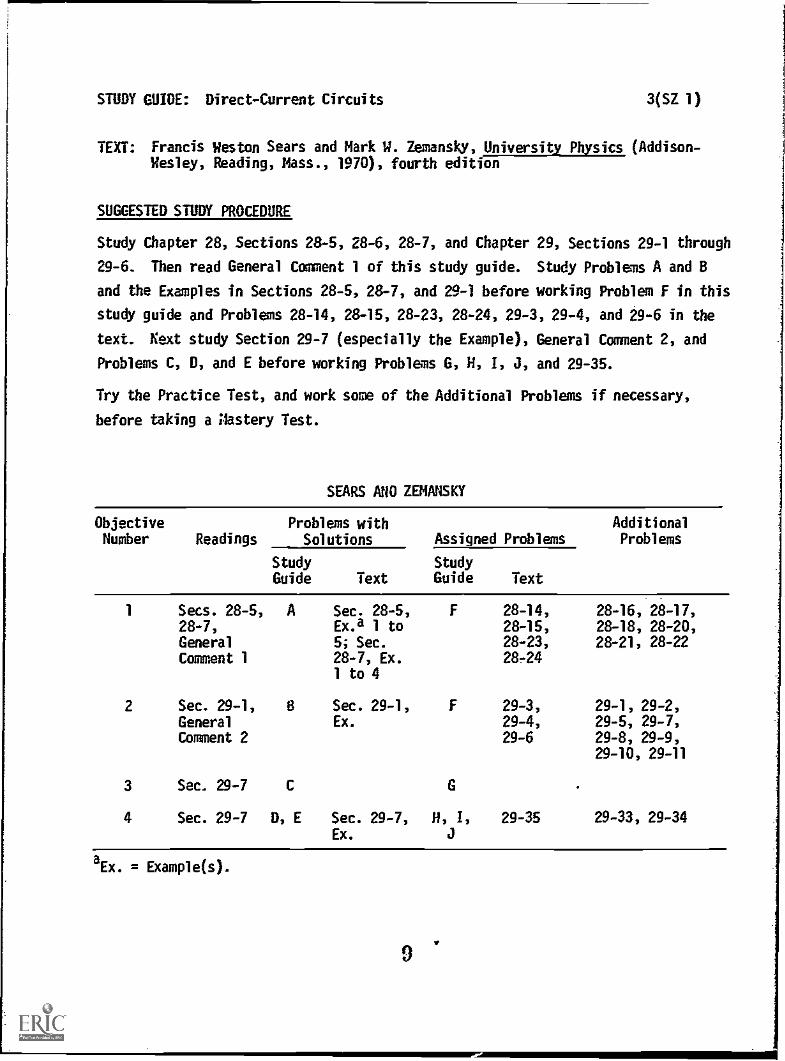
STUDY GUIDE: Direct-Current Circuits 3(SZ 1)
TEXT: Francis Weston Sears and Mark W. Zemansky, University Physics (Addison-Wesley, Reading, Mass., 1970), fourth edition
SUGGESTED STUDY PROCEDURE
Study Chapter 28, Sections 28-5, 28-6, 28-7, and Chapter 29, Sections 29-1 through
29-6. Then read General Comment 1 of this study guide. Study Problems A and B
and the Examples in Sections 28-5, 28-7, and 29-1 before working Problem F in this
study guide and Problems 28-14, 28-15, 28-23, 28-24, 29-3, 29-4, and 29-6 in the
text. Next study Section 29-7 (especially the Example), General Comment 2, and
Problems C, D, and E before working Problems G, H, 1, J, and 29-35.
Try the Practice Test, and work some of the Additional Problems if necessary,
before taking a Aastery Test.
SEARS AHD ZENANSKY
ObjectiveNumber Readings
Problems withSolutions Assigned Problems
AdditionalProblems
StudyGuide Text
StudyGuide Text
1 Secs. 28-5, A Sec. 28-5, F 28-14, 28-16, 28-17,28-7, Ex.a 1 to 28-15, 28-18, 28-20,General 5; Sec. 28-23, 28-21, 28-22Comment 1 28-7, Ex. 28 -24
1 to 4
2 Sec. 29-1, 8 Sec. 29-1, F 29-3, 29-1, 29-2,
General Ex. 29-4, 29-5, 29-7,Comment 2 29-6 29-8, 29-9,
29-10, 29-11
3 Sec. 29-7 C G
4 Sec. 29-7 D, E Sec. 29-7,Ex.
H, 1, 29-35 29-33, 29-34
aEx. = Example(s).
9
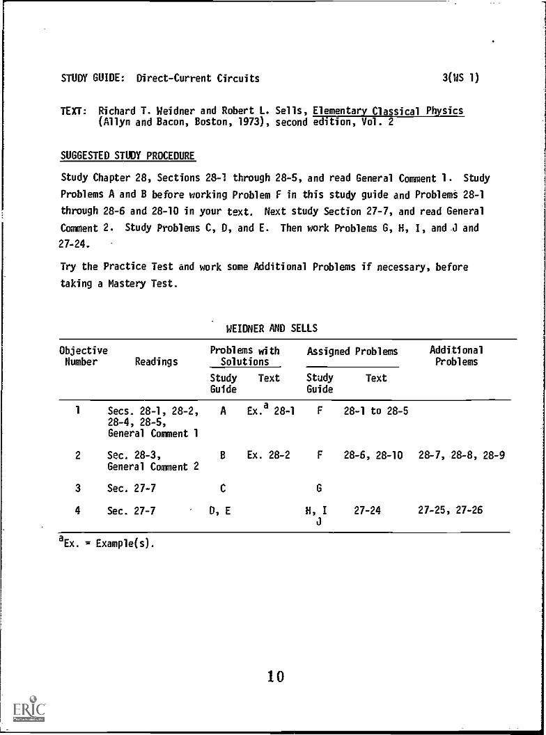
STUDY GUIDE: Direct-Current Circuits 3(WS 1)
TEXT: Richard T. Weidner and Robert L. Sells, Elementary Classical Physics(Allyn and Bacon, Boston, 1973), second edition, Vol. 2
SUGGESTED STUDY PROCEDURE
Study Chapter 28, Sections 28-1 through 28-5, and read General Comment 1. Study
Problems A and B before working Problem F in this study guide and Problems 28-1
through 28-6 and 28-10 in your text. Next study Section 27-7, and read General
Comment 2. Study Problems C, D, and E. Then work Problems G, H, I, and J and
27-24.
Try the Practice Test and work some Additional Problems if necessary, before
taking a Mastery Test.
WEIDNER AND SELLS
Objective Problems with Assigned Problems AdditionalNumber Readings Solutions Problems
Study Text Study TextGuide Guide
1 Secs. 28-1, 28-2, A Ex.a 28-1 F 28-1 to 28-528-4, 28-5,General Comment 1
2 Sec. 28-3, B Ex. 28-2 F 28-6, 28-10 28- 7, -28 -8, 28-9
General Comment 2
3 Sec. 27-7
4 Sec. 27-7 D, E H, I 27-24 27-25, 27-26
aEx. = Example(s).
10

STUDY GUIDE: Direct-Current Circuits 4
GENERAL COMMENTS 1
1. The Loop Equation,
The suggested procedure begins with a discussion of a seat of emf and the dis-
tinction between an emf and a potential difference. Next, the loop equation is
introduced and a sign convention established so that the equation can be applied
to particular circuits. The loop equation goes under a variety of aliases - loop
theorem, Kirchhoff's loop rule, etc., and is an application of the conservation
of energy. The main difficulty that you may have in applying the loop equation
will probably be in correctly using the sign convention. There are four differ-
ent directions (polarities) that are involved, and you need to be sure that you
understand these differences among them. First, there is the direction of an
emf which is independent of the direction of any current flowing though the
seat of emf and may be represented by an arrow 01----p and/or the battery- symbol
The second direction is the direction of the potential difference
across a resistor or between two points in a circuit. Note that Vab = Va Vb
b- V
a) -V
ba'and that the potential drop across a resistor does depend on
the direction of current flow through the resistor. The terminal of a resistor
at which the current enters is at a higher potential than the terminal from which
it leaves. The third direction is that in which the current flows in a particular
circuit element. Clearly, you must know the current direction in a resistor be-
fore you can determine the sign of the potential difference across a resistor,
and just as clearly you frequently do not know the current directions at the be-
ginning of solving a problem. The paradox is only apparent; simply assume a
direction for each current and any wrong assumptions will simply result in a
negative value for each wrong assumption. Be sure, however, to mark your assump-
tions on a circuit diagram so that you will use it consistently. The fourth
direction is the one you adopt to traverse a loop in applying the loop equation.
This direction is arbitrary and is not usually indicated on the circuit diagram.
To make the opposite choice, simply change the sign of each term in the loop equa-
tion. If you do not understand the distinctions among these directions, return
to your study of the text and examples until you do.
Your text discusses a number of applications of the loop equation, including manycases of two connected loops. These circuits add another equation that resultsfrom the conservation of charge. You should study these sections as applicationsof the loop equation, but you will not be tested on multiple-loop circuits requiring
STUDY GUIDE: Direct-Current Circuits 5
the solution of simultaneous equations. This exception does not include seriesand parallel resistance combinations, which you will be expected to reduce toa single equivalent resistance. The important thing to remember, both for de-riving the expressions for equivalent resistance and for applying the expressionsto simplify a circuit, is that a set of resistors is in series if the same cur-rent flows through each of them, and it is in parallel when the same potentialdifference appears across them.
2. Application of the Loop Equation
In this section we will consider a further application of the loop equation.When the loop equation is applied to a circuit with resistors and capacitors,the resulting equation is not simply an algebraic equation, but is a differen-tial equation chat has an implicit time dependence as a result of the-inter-dependence of the charge (Q) and current (I = dQ /dt). The solution of thisdifferential equation is not a number but a time-dependent function. In thiscourse, we will not deal with the mathematics of solving such equations, butwe will learn the general form of the solution and then check the solution tosee if it satisfies the differential equation. "Satisfies" means that when wesubstitute all pertinent derivatives of the proposed solution into the differen-tial equation we get an identity or an expression that can be made into an iden-tity by renaming some constants, and we thus have verified the solution. Thisprocedure was used in discussing traveling waves and in discussing simple har-monic motion.
The solutions of this module for RC circuits are of two types, one for charginga capacitor, the other for discharging a capacitor, respectively;
Q = EC(1e-t/RC) -t/RC
and Q = Qoe .
Each of these can be directly related to the voltage on a capacitor:
VC " )ce-t/RC. and VC =voe-t/RC
Both can also be related to a decreasing current
I = = ( le-t/RC
and I = la=vOi (_=)O-t/RCVn
t R dt
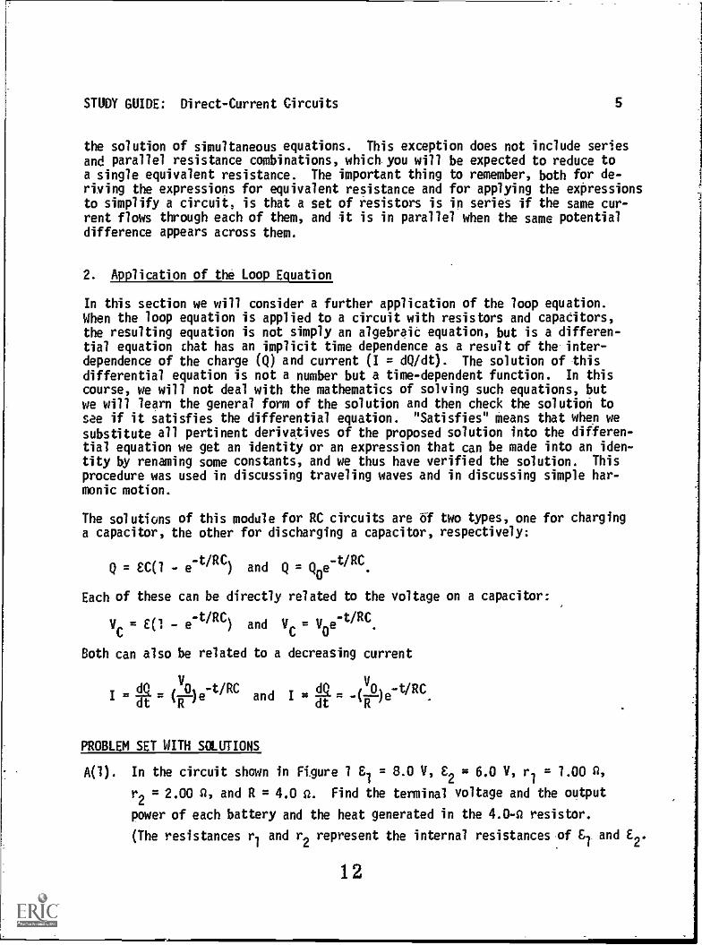
PROBLEM SET WITH SOLUTIONS
A(1). In the circuit shown in Figure 1 81 = 8.0 V, E2 = 6.0 V, r1 = 1.00 A,
r2 = 2.00 CI, and R = 4.0 2. Find the terminal voltage and the output
power of each battery and the heat generated in the 4.04 resistor.
(The resistances r1 and r2 represent the internal resistances of &I and E2.
12

STUDY GUIDE: Direct-Current Circuits 6
Solution
To begin the problem we need to find the current that will flow in the loop.This can be done by applying the loop equation starting at a and proceedingclockwise, noting that both emfs are in the positive sense as we traverse theloop and that we have assumed the current direction shown in the figure:
C2 - Ir2 + - - IR = 0.
This equation can be solved for the current:
£1 + C2 8.0 + 6.0
I = 2.00 A.r1+ r
2+ R 2.00 + 1.00 + 4.0
Any real battery consists of a seat of emf and an internal resistance, and wecannot have access to these separately. The terminal voltage of C2 is thepotential difference between a and b:
Vba
= Vb Va = C2 - Tr2= 6.0 - (2.00)(2.00) = 2.00 V.
Similarly,
Vdc Vd Vc = EiIr1 = 8.0 - (2.00)(1.00) = 6.0 V.
The power delivered to the external circuit is just the product VI, hence
. P1 = (6.0)(2.00) = 12.0 W, P2 = (2.00)(2.00) = 4.0 W,
and the heat generated in the 4.0-n resistor is
P = I2R = (2.00)
2(4.0) = 16.0.W,
which is conveniently the sum of the power supplied by the two batteries. Note
also that emf C2 Is supplying 621 = (6.0)(2.00) = 12.0 Ws but (2.00)2(2.00) =
8.0 W is generated as heat within the battery.
13
20S7
Figure 2
6S7
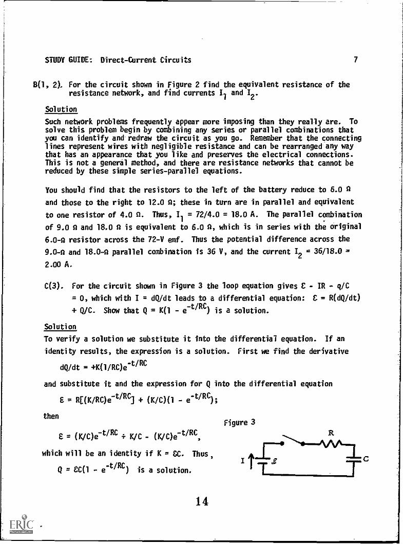
STUDY GUIDE: Direct-Current Circuits 7
B(1, 2). For the circuit shown in Figure 2 find the equivalent resistance of theresistance network, and find currents Il and I2 .
Solution
Such network problems frequently appear more imposing than they really are. Tosolve this problem begin by combining any series or parallel combinations thatyou can identify and redraw the circuit as you go. Remember that the connectinglines represent wires with negligible resistance and can be rearranged any waythat has an appearance that you like and preserves the electrical connections.This is not a general method, and there are resistance networks that cannot bereduced by these simple series-parallel equations.
You should find that the resistors to the left of the battery reduce to 6.0 A
and those to the right to 12.0 A; these in turn are in parallel and equivalent
to one resistor of 4.0 A. Thus, I1 = 72/4.0 = 18.0 A. The parallel combination
of 9.0 A and 18.0 A is equivalent to 6.0 A, which is in series with the original
6.0-A resistor across the 72-V emf. Thus the potential difference across the
9.0-A and 18.0-A parallel combination is 36 V, and the current 12 = 36/18.0 =
2.00 A.
C(3). For the circuit shown in Figure 3 the loop equation gives E IR - q/C
= 0, which with I = dQ /dt leads to a differential equation: C = R(dQ/dt)
+ QJC. Show that QK(i - e-t /RC) is a solution.
Solution
To verify a solution we substitute it into the differential equation. If an
identity results, the expression is a solution. First we find the derivative
dQ/dt = +K(1/RC)e-t/RC
and substitute it and the expression for Q into the differential equation
S = RUK/RC)e-t/RC) + (K/C)(1e-t/RC);
then
= (K/C)e-t/RC + K/C (K/C)e-tiRC,
which will be an identity if K = CC. Thus,
Q = eal e-t/RC) is a solution.
14
Figure 3

STUDY GUIDE: Direct-Current Circuits 8
0(4). For the circuit shown in Figure 4 find the voltage across the capacitorat 1.20 s after the switch is closed.
Solution
From the previous example the charge on the capacitor at any time is
q = CC(1e-t/RC).
Since the voltage on the capacitor is Vc
= q/C,
V = (EC/C)(1e-t/RC)
= (100 V)(1 -et/0.60 s),
where the time constant RC = (3.00 x 10⁵)(2.00 x 10⁻⁶) = 0.60 s. At t = 1.20 s,
V = (100 V)(1 -e-1.20/0.60 s.
) = (100 V)(1 1/e2) = 8.6 V.
E(4). For the circuit shown in Figure 5 the switch was placed in position a fora long time and then quickly moved to position b; 12.0 s 1,ter the voltageacross the capacitor was 1.00 V. Find the value of the capacitor.
2.00 pF
100 V
Figure 4
3X 1050
106ft
Figure 5
Solution
From the circuit we can conclude that the time constants for charging and dis-charging are about the same. Thus we can assume the capacitor was fully charged to8.0 V when the switch was moved to b and we can write
Vc = Ce-t/RC
= - 8.0e-t/10
6C
and for the problem values
1.00 = (8.0)e-12.0/1060
To evaluate C we take the natural logarithm of this expression. Rewriting it slightly
first we have
15

STUDY GUIDE: Direct-Current Circuits 9
12.0/106
e- C
= 0.12S, -12.0/106C = in 0.12S,
C = -12/(106 in 0.125) = 5.8 x 10⁻⁶ F = 5.8 aF.
With a scientific calculator this evaluation is straightforward. However, forpurposes of approximation many physicists like to estimate exponentials in termsof half-lives, and we note here that the reduction from 8.0 to 1.00 V representsthe passing of three half-lives:
t t t8 :li...2.4 7g02
7.
Thus the half-life is 4.0 s in this problem. For the expression V = Voe-t/RC
,
We take-t2/RC
V = V0/2 at t = V0/2 = Voe "
Again taking natural logarithms of both sides, we find
7n(1/2) = -t1/2/RC and t1/2 = RC in 2.0 = 0.69RC.
Thus in this case RC = 4.0/0.69 s and C = 4/(106)(0.69) = 5.8 x 10⁻⁶ F.
Problems
F(1, 2).. For the circuit shown in Figure 6 find the current I, and the power dissi-pated in the 17.0-0 resistor.
G(3). For the circuit shown in Figure 7 write the differential equation for the
voltage on the capacitor, if the voltage was Vo at t = 0. Show that V =
V0e- t/RC is a solution for your differential equation.
Figure 6
34S2
16
Figure 7
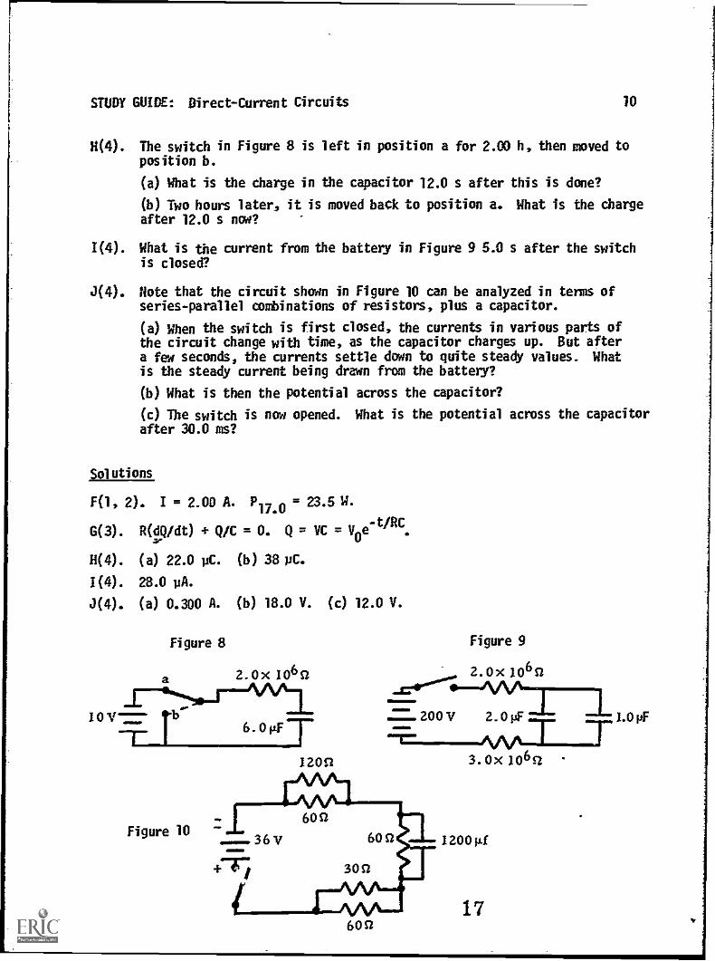
STUDY GUIDE: Direct-Current Circuits 10
H(4). The switch in Figure 8 is left in position a for 2.00 h, then moved toposition b.
(a) What is the charge in the capacitor 12.0 s after this is done?
(b) Two hours later, it is moved back to position a. What is the chargeafter 12.0 s now?
1(4). What is the current from the battery in Figure 9 5.0 s after the switchis closed?
J(4). Note that the circuit shown in Figure 10 can be analyzed in terms ofseries-parallel combinations of resistors, plus a capacitor.
(a) When the switch is first closed, the currents in various parts ofthe circuit change with time, as the capacitor charges up. But aftera few seconds, the currents settle down to quite steady values. Whatis the steady current being drawn from the battery?
(b) What is then the potential across the capacitor?
(c) The switch is now opened. What is the potential across the capacitorafter 30.0 ms?
Solutions
F(1, 2). I = 2.00 A. P17.0 = 23.5 W.
G(3). R(dQ /dt) Q/C = 0. Q = VCyoe-t/RC.
H(4) . (a) 22.0 pC. (b) 38 pC.
1(4). 28.0 pA.
J(4). (a) 0.300 A. (b) 18.0 V. (c) 12.0 V.
Figure 8
2.0x 1060
Figure 10
6.01/FT
1200
600
3.0x 1060
1 200µf
17
1.0 pF
STUDY GUIDE: Direct-Current Circuits 11
PRACTICE TEST
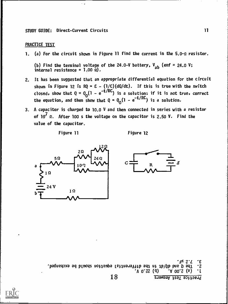
1. (a) For the circuit shown in Figure 11 find the current in the 5.0-n resistor.
(b) Find the terminal voltage of the 24.0-V batterY, Vab (emf = 24.0 V;internal resistance = 1.00 n).
2. It has been suggested that an appropriate differential equation for the circuit
shown in Figure 12 is RQ = E - (1/C)(dQ/dt). If this is true with the switch
closed, show that Q = Q0(1 - e-t/RC) is a solution; if it is not true, correct.
the equation, and then show that - et/RC)is a solution.
3. A capacitor is charged to 10.0 V and then connected in series with a resistor
of 107
f. After 100 s the voltage on the capacitor is 2.50 V. Find the
value of the capacitor.
Figure 11 Figure 12
*Ad Z' *Epa6ueipxa aq wogs uopenba Lepuaaallip aql ut 1p/Op pue b au '2
'A O'n (q) 'V 00*Z (e)
18 saamsuy ;sal 847.0ead
DIRECT-CURRENT CIRCUITS Date
Mastery Test
Name
Form Apass recycle
1 2 3 4
Tutor
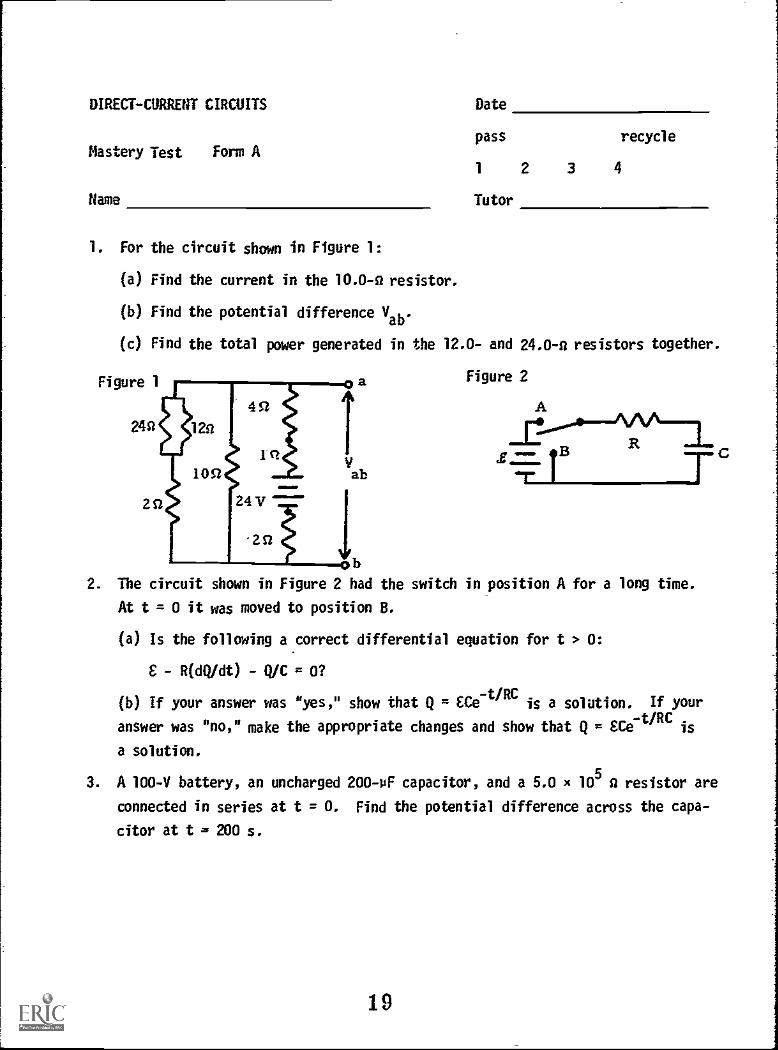
1. For the circuit shown in Figure 1:
(a) Find the current in the 10.0-a resistor.
(b) Find the potential difference Vab.
(c) Find the total power generated in the 12.0- and 24.0-a resistors together.
Figure 1 Figure 2
A
Vab
2. The circuit shown in Figure 2 had the switch in position A for a long time.
At t = 0 it was moved to position B.
(a) Is the following a correct differential equation for t > 0:
C R(dQ /dt) - QIC = 0?
(b) If your answer was "yes," show that Qac t/RC
is a solution. If your
answer was "no," make the appropriate changes and show that Q = SCe-t/RC
a solution.
3. A 100-V battery, an uncharged 200-pF capacitor, and a 5.0 x 10⁵ a resistor are
connected in series at t = 0. Find the potential difference across the capa-
citor at t = 200 s.
19
DIRECT-CURRENT CIRCUITS Date
Mastery Test Form B
Name
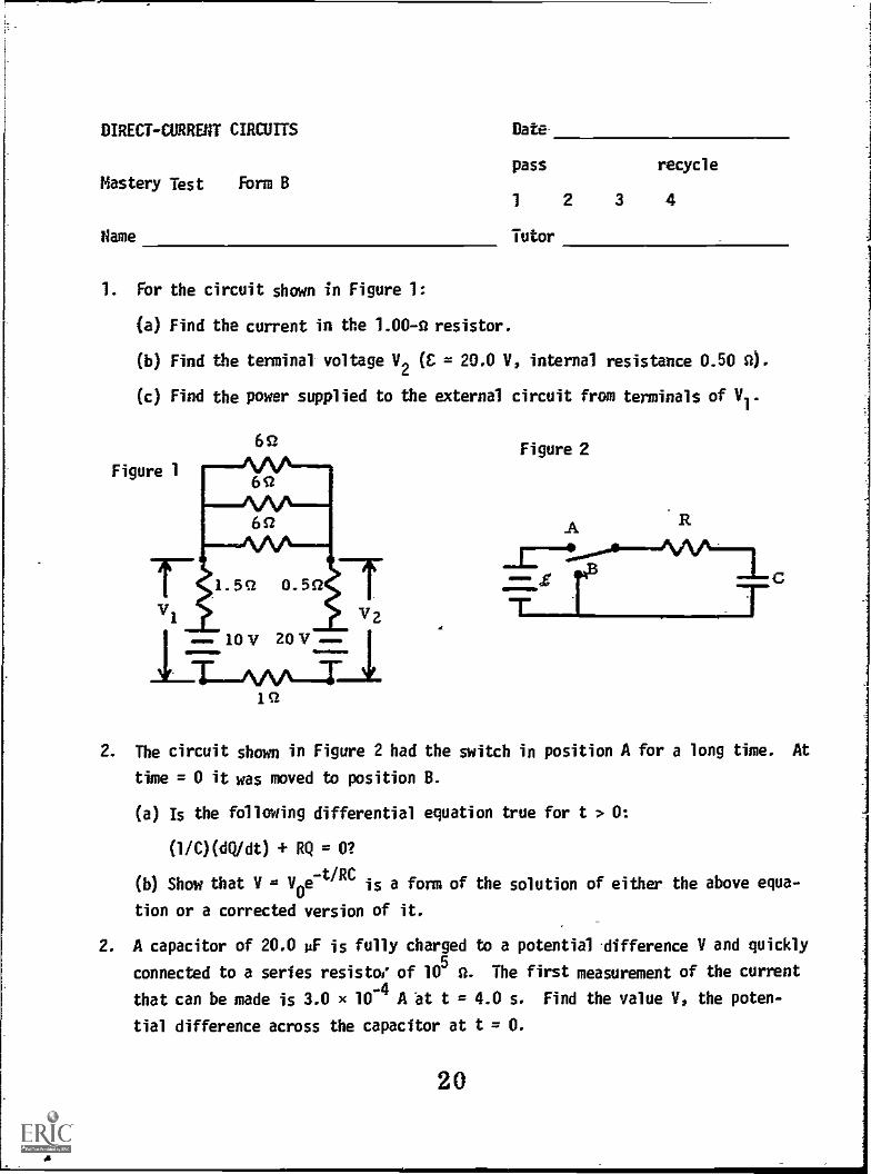
1. For the circuit shown in Figure 1:
(a) Find the current in the 1.00-0 resistor.
(b) Find the terminal voltage V2 (C = 20.0 V, internal resistance 0.50 0).
(c) Find the power supplied to the external circuit from terminals of V1.
pass recycle
1 2 3 4
Tutor
Figure 1
vi
6S-1
1.551 0.551
101/ 201/IN.ftWO
Figure 2
A R
2. The circuit shown in Figure 2 had the switch in position A for a long time. At
time = 0 it was moved to position B.
(a) Is the following differential equation true for t > 0:
(l /C)(dQ/dt) + RQ = 0?
(b) Show that V = V0e-t/RC
is a form of the solution of either the above equa-
tion or a corrected version of it.
2. A capacitor of 20.0 uF is fully charged to a potential difference V and quickly
connected to a series resistor' of 105
O. The first measurement of the current
that can be made is 3.0 x 10⁻⁴ A at t = 4.0 s. Find the value V, the poten-
tial difference across the capacitor at t = 0.
20
DIRECT-CURRENT CIRCUITS
Mastery Test
Name
Form C
Date
pass
1
Tutor
recycle
2 3 4
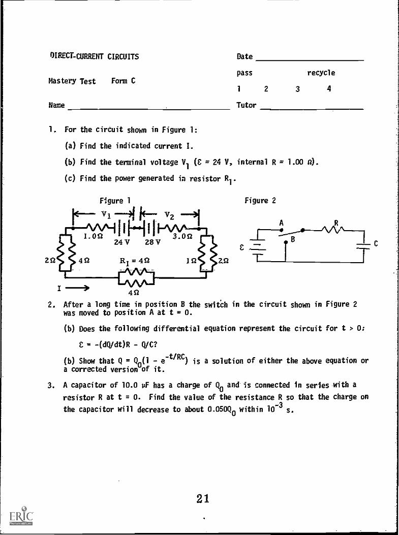
1. For the circuit shown in Figure 1:
(a) Find the indicated current I.
(b) Find the terminal voltage V (E = 24 V, internal R = 1.00 a).
(c) Find the power generated in resistor R1.
Figure 1
Vl 41 j Arz
Lost ANTI 3.0224V 28V
2S1 4S1
I -1R =4S1
Oft
2. After a long time in position B thewas moved to position A at t = 0.
(b) Does the following differential
E = -(adt)R Q/C?
Figure 2
A
switch in the circuit shown in Figure 2
equation represent the circuit for t > 0:
(b) Show that Q = Qn(1 e-t/RC
) is a solution of either the above equation ora corrected version of it.
3. A capacitor of 10.0 vF has a charge of Q0 and is connected in series with a
resistor R at t = 0. Find the value of the resistance R so that the charge on
the capacitor will decrease to about 0.050Q0 within 10-3 s.
21

DIRECT-CURRENT CIRCUITS
MASTERY TEST GRADING KEY - Form A1
1. What To Look For: (a) Correct answer. (b) You may note that the easiest
way to get the answer is from an intermediate step at which it is clear that
the current through the 10.0-2 resistor is 1.00 A, hence Vab = 10.0 V. The
implied 24.0 - (7.0)(2.00) = 10.0 V is, of course, acceptable. (c) The simplest
calculation is, of course, from the equivalent resistance, 8.0 2 and current,
1.00 A.
Solution: (a) 1.00 A. (b) 10.0 V. (c) P = I2R = 12(8) = 8 W.
2. What To Look For: (a) If the answer is simply "no" ask "why"? (b) Be surethe correct differential equation is given and that the derivative is correctand the substitution is correctly done.
Solution: (a) The equation is not correct. It is for the switch in position A.The equation for position 8 is
R(dQ/dt) Q/C = 0.
(b)Q
cce-t/RC,dQ/dt = -(C/RC)e-t/RC
Substituting in above equation, we find
(REC/RC)etiRCccet/RCic . _£e-t/RC ce-t/RC
which is an identity; therefore Q = ECe-t/RC
is a solution.
3. What To Look For: If the answer is incorrect check to find out if theequation was wrong or if the student made an error in numerical computation.
Solution: V = V (10
e-r/RC e) = 100(1 --200/100
) = 86 V.
22
DIRECT-CURRENT CIRCUITS
MASTERY TEST GRADING KEY - Form 8
8-1
1. What To Look For: (a) Check numerical answer. (b) The result should follow
easily from (a). If part (a) is wrong, check work to see if a correct value of
I would give the right answer. (c) Probably most easily calculated from VII, but
also acceptable is El - I2R.
Solution: (a) 6.0 A. (b) 17.0 V. (c) 6.0 W.
2. What To Look For: (b) Check for the correct differential equation, correctderivative dQ /dt, and correct substitution of one into the other.
Solution: (a) The equation given is incorrect. It should be
R(dQ /dt) Q/C = 0.
voe-t/RC, cvoe-t/RC,dQ/dt = -(CV0/RC)e-tiRC.
Substituting, we find
-(RCto/RC)eti RC (1/C)Clice-tiRC = 0,
which is an identity; therefore V = V0e-tiRC is a solution.
3. What To Look For: If the answer is incorrect check to find out if the equa-tion used was wrong or if the numerical evaluation was incorrect.
Solution: I = (V/R)e-tiRC,
Y/Re-t/RC = (3.0 /0-4)(105)e4.0/2.00
= 220 V.
23

DIRECT-CURRENT CIRCUITS C-1
MASTERY TEST GRADING KEY - Form C
1. What To Look For: (a) Correct answer. (b) Neither 24- nor 23.5 are correct.(b) and (c) If the answer in (a) is wrong, check to see if the work is correct.
Solution: (a) 0.50 A. (b) V = + IR = 24.5 V. (c) P/2R
(1/4)2(4)t4 = 0.250 -W.
2. What To Look For: Check for a correct differential equation, correct differ-entiation and correct substitution into the differential equation.
Solution: (a) The equation does not represent the circuit. It should be
- R(dQ/dt) - Q/C = 0.
(b)-e-t/RC) Q0(40e-t/RC = (Q2)et/RC.
Substituting, we find
E:Qco e-t/RC QO 40)e-t/RC
which is an identity if Q0 = EC.
3. What To Look For: If the answer is incorrect, check to see if the equationwas chosen or used incorrectly or if the numerical evaluation was wrong.
Solution: Q = Q0e-t/RC = e
-t/RC
t 103
in Q/Q0 = -t/RC, R =C in Q/Q C in(Q/
-50)
= 33 2.10 in(1.00/0.050)
24
Module
STUDY GUIDE
MAGNETIC FORCES
1
InTRODUCTION
It may surprise you to learn that the conversion of electrical energy to mechanicalwork in electric motors or stereo loud speakers is seldom done by electrostaticforces (Coulomb's law). Magnetic forces associated with moving charges (-currents)are the basis of most electromechanical devices. In analogy with the electrostaticcase, we introduce an intermediary called the magnetic field. This module considerSthe forces on currents or moving charges in a magnetic-field; the module Ampere'sLaw will show how magnetic fields are generated by currents.
PREREQUISITES
Before you begin this module,you should be able to:
Location of
'Prerequisite Content
*Calculate vector products (needed forObjectives 1-through-4' of this module }
*Define electric charge and field (neededfor Objectives 1 and 4 of this module)
*Define current in terms of carrier densityand velocity (needed for Objectives 2 through'4 of this module)
Vector Multiplication-Module
Coulomb's Law and theElectric Field Module
Ohm's LawModule
LEARNING OBJECTIVES
After you have mastered the content of this module, you will be able to:
1. Magnetic force - particles - Calculate the force on a moving charged particlein a uniform magnetic field; for the case of v perpendicular to t, find theradius and/or frequency of the resulting circular orbit.
2. Magnetic force - wires - Calculate the force on a current-carrying wire in auniform magnetic field.
3. Magnetic dipole - Calculate the magnetic moment of a current loop; use thisto determine the torque on such a loop in a uniform magnetic field.
4. Hall effect - For problems with balanced electric and magnetic forces (Halleffect, velocity selectors) use the relation v = E/8 to relate the fields toparameters such as the Hall field or potential difference, current density,or charge sign and velocity.
25
STUDY GUIDE: Magnetic Forces 2
GENERAL COMMENTS
Be sure that you are able to find the vector (cross) product of two vectors beforereading any further. It is essential to everything in this module. Unlike electricforces and electric fields, magnetic forces are perpendicular to the magnetic field,a relation described mathematically by the cross product.
You will find that a closed circuit carrying a current I experiences a total force(not torque) equal to zero if it is in a uniform magnetic field. An interestingconsequence is that the force on a part of such a circuit is independent of thepath of the current, and hence is the same As the force on a straight wire con-necting the end points.
Notice that although a magnetic dipole (a current-carrying loop) in a magneticfield behaves just like an electric dipole in an electric field, it is a verydifferent object internally. There are no known magnetic charges; the magneticdipole is a circulating current of electric charge (current loop), which producesthe same fields far from the dipole and experiences the same torques as a dipolemade from a charge pair.
We also consider the case in whickS, !!, and t form a right-handed set of orthogonalvectors like i4, j, and k. If r = B x v, then the total force on a charge movingwith velocity v is zero. This is the basis of velocity filters for charged particles.It also- occurs if a current- carrying conductor 14; placed in a magnetic field. Thecharge carriers are displaced in the direction qv x g until an electric force 4caused by the excess charge on one lide makes the net transverse force on the charge
Ecarrier equal to zero. This field is called the Hall field, and is used to invest-igate the sign and density of charge carriers in a conductor. One can also use itto measure the magnetic field.
26

STUDY GUIDE: Magnetic Forces 3(8 1)
TEXT: Frederick J. Sueche, introduction to Physics for Scientists and Engineers(McGraw-Hill, New York, 1975), second edition
SUGGESTED STUDY PROCEDURE
Your text readings are from Chapter 23. Read the General Comments; then gothrough the textbook in the order given in the Table. As you complete the sectionfor each objective, study the corresponding Problems with Solutions in the ProblemSet; then work the Assigned Problems until you have mastered the associatedobjective. Then take the Practice Test.
An important application of the principles of Objective 1 arises from Illustration23.5, where there is a calculation of the period of the circular orbit of aparticle of mass in in a uniform field B. The general result is T = 2vm/qB indepen-dent of the particle energy. This fact is used in the particle accelerator calledthe cyclotron. Since the period is energy independent, an alternating electricfield Ey = EO sin(2nt /T) will accelerate the particle. The energy, momentum, andorbit radius all increase as long as the particle remains in both the electric andthe magnetic field. This principle is used to accelerate particles to highenergies for nuclear research, to study electrons in solids, and to heat ionizedgases in thermonuclear research.
BUECHE
Objective Readings Problems with Assigned Problems AdditionalNumber Solutions Problems
Study Text Study TextGuide Guide
2 Secs. 23.1 to B Illus.a E, F 1, 2, 3 4, 16
23.4 23.1,
23.2,23.3
1 Sec. 23.5 A Illus. D 5, 8, 9 10, 1123.4,23.5
3 Secs. 23.7, 23.8 C E 13, 14, 15
4 Sec. 23.6 D Illus. G 7
23.6
aIllus. = Illustration(s).
2?

STUDY GUIDE: Magnetic Forces 3(HR 1)
TEXT: David Halliday and Robert Resnick, Fundamentals of Physics (Wiley,New York, 1970; revised printing, 1974)
SUGGESTED STUDY PROCEDURE
All of your text readings are in Chapter 29. Read the General Comments; then gothrough the textbook in the order given in the Table below. As you complete thereading for each objective, study the corresponding Problems with Solutionsin the Problem Set; then work the Assigned Problems until you have mastered theassociated objective. Take the Practice Test and work some Additional Problemsif necessary before trying a Mastery Test.
HALLIDAY AND RESNICK
Objective ReadingsNumber
Problems withSolutions
Assigned Problems AdditionalProblems
Study
Guide
Text StudyGuide
Text
,
1 Secs. 29-1, 29-2, A Exa. 1, D 1, 5, 21: 4, 6, 2329-6, 29-7 4, 5 25
2 Sec. 29-3 B E, F 7, 9, 11 8, 10, 12
3 Sec. 29-4 C Ex. 2 E 13, 15 16
4 Secs. 29-5, 29-8 D G 19, 41 18, 20, 42
. = Example(s).
28
STUDY GUIDE: Magnetic Forces 3(SZ 1)
TEXT: Francis Weston Sears and Mark W. Zemansky, University Physics (Addison-Wesley> Reading, Mass-, 1970), fourth edition
SUGGESTED STUDY PROCEDURE
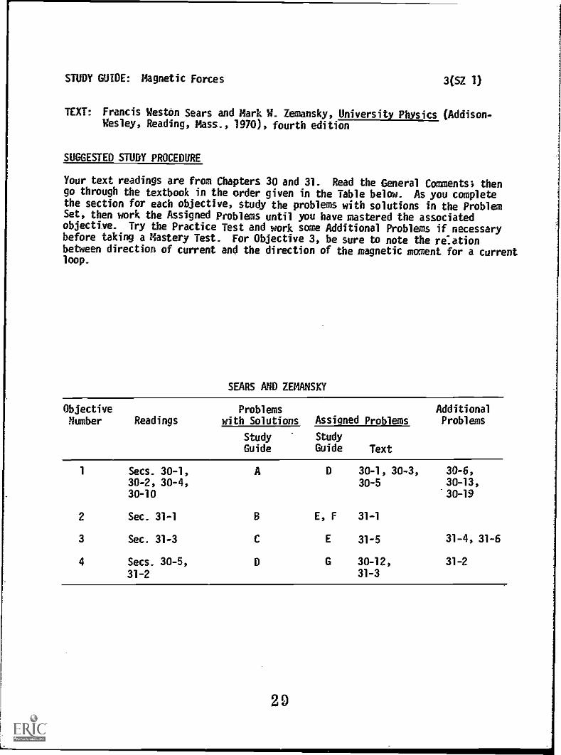
Your text readings are from Chapters 30 and 31- Read the General Comments; thengo through the textbook in the order given in the Table below. As you completethe section for each objective, study the problems with solutions in the ProblemSet, then work the Assigned Problems until you have mastered the associatedobjective. Try the Practice Test and work some Additional Problems if necessarybefore taking a Mastery Test. For Objective 3, be sure to note the re:ationbetween direction of current and the direction of the magnetic moment for a currentloop.
SEARS AND ZEMANSKY
Objective Problems AdditionalNumber Readings with Solutions Assigned Problems Problems
Study Study
Guide Guide Text
1 Secs. 30-1,30-2> 30-4>30-10
2 Sec. 31-1
3 Sec. 31-3
4 Secs. 30-5,
31-2
A D 30 -1, 30 -3, 30-6>
30-5 30-13,
30 -19
8 E, F 31-1
C E 31-5 31-4, 31-6
D G 30-12, 31-2
31-3
29

STUDY GUIDE: Magnetic Forces 3(145 1)
TEXT: Richard T. Weidner and Robert L. Sells, Elementary Classical Physics(Allyn and Bacon, Boston, 1973), second edition, Vol. 2
SUGGESTED STUDY PROLEDURE
Your text readings are from Chapter 29. Read the General Comments; then gothrough the textbook in the order given in the Table below. As you completethe section for each objective, study the corresponding Problems with Solutionsin the Problem Set; then work the Assigned Problems until you have mastered theassociated objective. Take the Practice Test and work some Additional Problemsif necessary before trying a Mastery Test.
WEIDNER AND SELLS
ObjectiveNumber
Readings Problems withSolutions
Assigned Problems AdditionalProblems
StudyGuide
Text StudyGuide
Text
1 Secs. 29-1, A Exa. D 29-1, 29-3, 29-4, 29-829-3, 29-5 29-2,
29-329-11
2 Sec. 29-6 B Ex. E, F 29-16b
29-1729-4
3 Secs. 29-7, C E 29-18 29-20, 29-21,
29-8 29-23
4 Secs. 29-4, F Ex. G 29-9, 29-24
29-9 29-5
aEx. = Example(s).
bI = (mg/LB) tan e. 30
STUDY GUIDE: Magnetic Forces 4
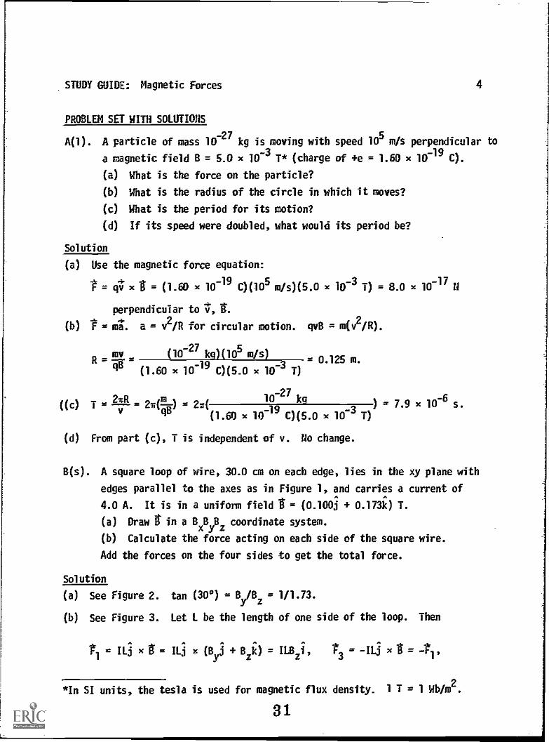
PROBLEM SET WITH SOLUTIONS
A(1). A particle of mass 10727
kg is moving with speed 105m/s perpendicular to
a magnetic field B = 5.0 x 10⁻³
T* (charge of +e = 1.60 x 10719
C).
(a) What is the force on the particle?
(b) What is the radius of the circle in which it moves?
(c) What is the period for its motion?
(d) If its speed were doubled, what would its period be?
Solution
(a) Use the magnetic force equation:
= 4; x - (1.60 x 10⁻¹⁹ C)(105 m/s)(5.0 x 10-3 = 8.0 x 10⁻¹⁷ n
perpendicular to v, tr.
(b) = a. a = v2/R for circular motion. qvB = m(v2/R).
((c)
R= my (10-27 kg)(105 m/s)= 0.125 m.
4IP (1.60 X7e9
0)0.0 x 10³ 11
2) = 2N(
10-27
kg) = 7.9 x 10⁻⁶ s.T = --41--= 2N(--m
v(1.60 x 10⁻¹⁹ C)(5.0 x 10-'1 1)
(d) From part (c), T is independent of v. no change.
B(s). A square loop of wire, 30.0 cm on each edge, lies in the xy plane with
edges parallel to the axes as in Figure 1, and carries a current of
4.0 A. It is in a uniform field = (0.100j 0.173k) T.
(a) Draw tin a Bx yB..0 coordinate system.
(b) Calculate the force acting on each side of the square wire.
Add the forces on the four sides to get the total force.
Solution
(a) See Figure 2. tan (300) = By/Bz = 1/1.73.
(b) See Figure 3. Let L be the length of one side of the loop. Then
= IL3 x = ILj x (Byj Bzii) = ILBzi, D3 = x g =
*In SI units, the testa is used for magnetic flux density. 1 T = 1 Wb/m2.
31

STUDY GUIDE: Magnetic Forces
F2 = -111 x (8) + Bzk) = + IL8i,
Since F3 = -t3 l' 4 2'
4. 1.2 4- t3 = 4' 4t2 - V.2 = 0
which is always the case in a uniform field.
ILSy = (24 A)(0.300 14(0.100 T) = 0.120 H, 11.8z = 0.210 N.
Figure I Figure 2
5
x -t2.
0.173T
B2
.01M. .1111. .110
0.1T
Figure 3
C(3). For the same loop as in Problem B (Figure 1),(a) What is the vector dipole moment of the loop?(b) Using the result of part (a), find the vector torque acting on theloop.
Solution
(a) v = IAk, where I is the current, and A is the cross-sectional area of the
loop. The direction of .1: follows a right-hand rule; if fingers follow the
current, the thumb picks the correct normal to the loop. Hence
V
= [(4.0 A)(0.300 n)2fc = 0.36k A m2.
(b) 1 = 'LI' x g. = k x (Byj ezi) = -0; = -0.036i H m.
D(1, 4). A particle in Figure 4 moving with speed 106 m/s along the y axis
enters a magnetic field t = 80k, B0 = 0.40 T, q = 1.60 x 10⁻¹⁹ C,
m = 10-27 kg.32

STUDY GUIDE: Magnetic Forces 6
(a) What is the force on the particle?(b) What will be the path of the particle if it stays in the field?(c) What electric field E will result in zero net force on the particle?
Solution
(a) 1.= 4; x t:= (1.60 x 10⁻¹⁹ c)(106i m /s)(0.40k -1) = 6.4 x 10-44i N.
(b) A circle parallel to the xy plane:
mv (10--27
kg) l06 m/s)R = ra z 1.56 x 10r2
m.B (1.60 x i0 T)
x 0.
E= v x t:= (-106i m/s)(0.40i T) = -4.0 x 10⁵i Y/m.
(c)
Problems
E(2, 3). A square loop as shown in Figure 5 is pivoted about the z axis and carriesa current I = 10.0 A. The loop is in a uniform magnetic field B = 0.50 Tparallel to the y axis.(a) What is the magnitude and direction of force on the side labeled a?(b) What torque is acting on the loop? (Give magnitude and direction.)
(c) What is the total force on the loop?
Figure 4
F(2).
Figure 5
In Figure 6 a copper rod weighing 2.00 N rests on two horizontal rails1.00 m apart and carries a current of 50 A from one rail to the other.The coefficient of static friction u is 0.60. What is the smallestvertical magnetic field that would cause the bar to slide, and what isits direction? Remember that the frictional force = u (normal force).
G(4). The conductor in Figure 7 with square cross section and side a = 0.0250 m
carries a current I = 100 A. A magnetic field B0 = 0.60 is parallel to
33

STUDY GUM: Magnetic Forces 7
the positive z axis. The current is carried by electrons with
q = -1.60 x 10⁻¹⁹ C.
(a) What is the direction of the Hall field?
(b) If the density of carriers is 4.0 x 1028 per cubic meter, what is
the speed of the electron?
(c) What is the Hall voltage?
Figure 6 Figure 7
Solutions
E(2, 3). (a)... t = IL x = (10.0 A)(0.100...m)(i/q+ j /I)(0.57)j = 0.35k N.
(b) u = IA(-i //2 -+ j//i) = (0.100 A m2)(-1/12-+
"i); x = (0.100 A m2)(-i/e2-+ 3//i)(0.57)3 = - 0.035k N m.
(c) t = 0 for closed loop in uniform field.
F(2). B = 0.0240 T up. The rod would move to the right.
G(4). (a) Since carriers have negative chlrgeo_they go t2 the left if the currentis to the right. Hall condition is F = q[E + (v x 8)] = 0.
t = =v x .6 points along the positive x axis.
(b) I = nqvA,
=I
, = 2.50 x 10⁻⁵
m/s.
(4.0 x 1028/m3
100 A
)(1.60 x 10⁻¹⁹ C)(0.025 m)(-
3 4
STUDY GUIDE: Magnetic Forces
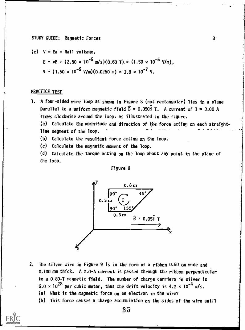
(c) V = Ea = Hall voltage,
E vB = (2.50 x 10 5 mis)(0.60 7). = (1.50 x 10⁻⁵ V/m),
V is (1.50 x 10- 5V/m)(0.0250 m) = 3.8 x 10⁻⁷ V.
8
PRACTICE TEST
1. A four-sided wire loop as shown in Figure 8 (not rectangular) lies in a plane
parallel to a uniform magnetic field = 0.0501 T. A current of I = 3.00 A
flows clockwise around the loop, as illustrated in the figure.
(a) Calculate the magnitude and direction of the force acting on each straight-
line segment of the loop.
(b) Calculate the resultant force acting on the loop.
(c) Calculate the magnetic moment of the loop.
(d) Calculate the torque acting on the loop about any point in the plane of
the loop.
Figure 8
0.6m190° 45.
0.3m190° 135°
0.3m= 0.05i T
x
2. The silver wire in Figure 9 is in the form of a ribbon 0.50 cm wide and
0.100 mm thick. A 2.0-A current is passed through the ribbon perpendicular
to a 0.80-T magnetic field. The number of charge carriers in silver is
6.0 x 1028
per cubic meter, thus the drift velocity is 4.2 x 10⁻⁴
m/s.
(a) What is the magnetic force on an electron in the wire?
(b) This force causes a charge accumulation on the sides of the wire until

STUDY GUIDE: Magnetic Forces 9
the magnetic force is balanced by an equal electric force. What are the
magnitude and direction of the electric field thus produced?
(c) What is the Hall voltage produced across the width of the ribbon?
Figure 9
B
OA 0 nun
3. A charged particle is accelerated through a potential difference of 5000 Y,then enters a magnetic field of magnitude 0.300 T with its velocityperpendicular to the direction of the magnetic field. This particle has acharge-to-mass ratio of q/m = 4.0 x 10⁶ C/kg.(a) Find its speed v.(b) Use the basic magnetic force law to find the radius of its path.
ie L9P0 = D (q) 'situ cOl x 00.Z = A (e) E
A 9- x 'I = 0)'w/A 4_01 x E'E- = (q) 'N .6_01 x E'Sr
01
x
S9411)
(eA
()
'Z
'w N EOZO*0- = 42: (p)
'el V lite0- = 4 (3) WUOIttle JOI Skehtle Se 0 = 0E + Z + (q)
01 unfitl
'N 100'0 n 114,40
4N 100'0- = 34 40 = '0i am61.1 eas (e)
36sJamsuv lsai 831.13eJd

MAGNETIC FORCES Date
Mastery Test Form A Tess recycle
1 2 3 4
Name Tutor
1 . A gold strip 1.50 an wide and 0.100 cm thick is placed in a gfield of
2.00 Wb/m2 at right angles to the strip. A current of 100 A is set up in the
strip along its length. Let n = 6.0 x 1028 per cubic meter and
q = -1.60 x 10 19C.
(a) Sketch the setup. Include a set of coordinate axes.
(b) What is the velocity of the charge carriers? Assume they are electrons.
(c) What is the magnetic force on an electron?
(d) What Hall potential difference appears across the strip? Indicate the
direction of the Hall field in your diagram.
2. A straight wire of length L carrying a current I is situated in a uniformB field directed at right angles to the wire segment. Draw a diagram showingthe directions of the current in the wire, the g field, and the magnetidforce acting on the wire. What is the magnitude of the magnetic force?Now imagine that the wire segment is bent into the form of a closed circularloop, the plane of which is oriented at an angle 0 to the field, as inFigure 1. What is the net force on the loop? What is the net torque of theloop? (sin 0)(-i) + (cos 0)3 is the normal to the loop.
37

MAGNETIC FORCES
Mastery Test Form 8
Name
Date
pass recycle
1 2 3 4
Tutor
1. At the instant a positive ion of charge +e and mass m traveling to the right
with a velocity .191.= voi passes through the origin of a coordinate system as
shown in Figure 1, a uniform g' field directed perpendicular to the xy plane
i is established and causes the ion to pass through the point x = R, y = R, z = O.
(a) Determine the magnitude of the field in terms of e, m, and 10%
(b) Is the if field directed into or out of this exam sheet?
(c) What is the velocity (magnitude and direction) of the ion at (R, R, 0)?
(d) How long does it take to make one turn?
An electric field is introduced to cause a second ion entering the g' field at
the origin of the coordinate system to continue in a straight line with aA
velocity v = voi.
(e) Indicate the direction of the t field.
(f) Determine the magnitude of the t field in terms of the parameters given.
2. In Figure 2 a wire bent into a semicircular arc of radius R in the yz plane
carries a current I. A uniform external magnetic field go is parallel to the
x axis. Find the vector force acting on the wire. Remember that closed loops
have zero net force.
3. A flat coil of 20 turns, with an area of 20 cm2
is suspended in -a magnetic
field of strength B = 0.300 Wb/m2
. When the plane of the coil makes an angle
of 450 with the field, the torque has a magnitude of 1.00 x 10⁻²
N m.
(a) What is the magnetic moment of the coil?
(b) What is the current flowing in the coil?
Pe%
v
(R, R, n)
x
Figure 1 38

MAGNETIC FORCES Date
Mastery Test Form C pass recycle
1 2 3 4
Name Tutor
1 (a) What is the speed of a proton (charge q = 1.50 x 10⁻¹⁹ C and mass m =
1.70 x 10⁻²⁷ kg) that moves in a circle of 2.00 m radius in a t field of
0.200 Wbfm2?
(b) If the speed is doubled, how does the time for one turn change?
(c) If the velocity of the proton is now along i and the magnetic field is
along k, what electric field (direction and magnitude) will cause the velocity
to remain constant?
2. The wires of a high-voltage electric power transmission line experience a
magnetic force from the Earth's magnetic field. Find the magnetic force
per meter of its length if a wire carries a current of 500 A in the local .
(magnetic) northerly direction. The Earth's field is 2.50 x 10⁻⁵ Wb/m2 and
points northward and downward at 70° from the horizontal. Illustrate your
solution with a sketch of the problem.
3. You wish to make a square coil out of a 1.00-m-long piece of wire such that
it experiences a maximum torque of 0.200 N m when it carries a 4.0-A current
and is placed in a uniform 0.84-Wb/m2 field. Now many turns should it have?
39
MAGNETIC FORCES
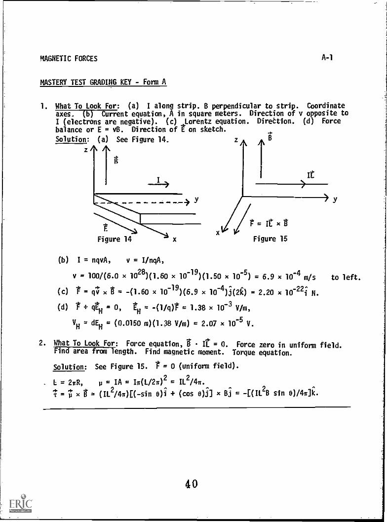
MASTERY TEST GRADING KEY - Form A
A-1
1. What To Look For: (a) I along strip. B perpendicular to strip. Coordinateaxes. (b) Current equation, A in square meters. Direction of v opposite to
I (electrons are negative). (c) Lorentz equation. Direttion. (d) Force
balance or E = vB. Direction of t on sketch.
Solution: (a) See Figure 14.
1/4 =ICxgFigure 15
(b) I = nqvA, v = I/nqA,
v = 100/(6.0 x 1028)(1.60 x 10⁻¹)(1.50 x 10⁻⁵) = 6.9 x 10⁻⁴ m/s
(c) t = qv x u -(1.60 x 10-g)(6.9 x 10⁻⁴)3(2k) = 2.20 x 10⁻²²i N.
(d) t qtH = 0, = -(1/0t = 1.38 x 10⁻³ V/m,
VW = dEH = (0.0150 m)(1.38 V/m) = 2.07 x 10⁻⁵ V.
2. What To Look For: Force equation, it = O. Force zero in uniform field.Pind area from length. Find magnetic moment. Torque equation.
Solution: See Figure 15. 1.= 0 (uniform field).
I = 2nR, p = IA = IsiL/2112 = 11.2/47.
1 = x = (IL2 /4)[( -sin e)i + (cos e)3) x Bj = -[(IL2B sin 0/474.
y
to left.
40
MAGNETIC FORCES
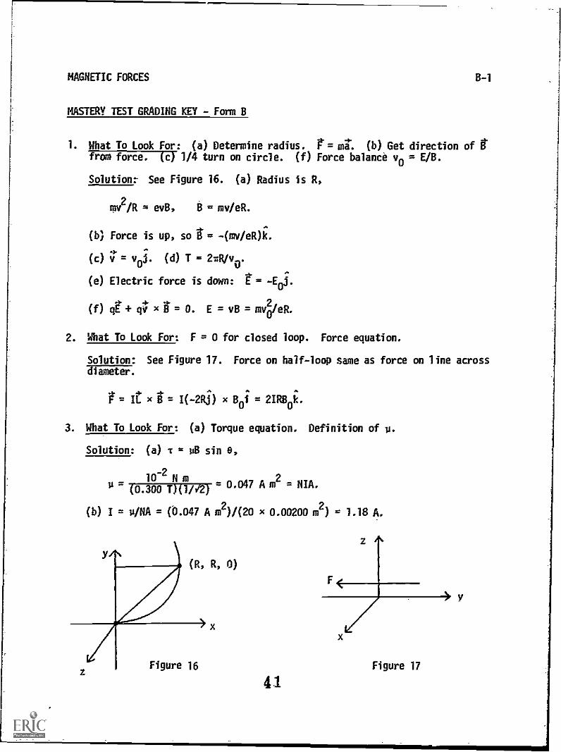
MASTERY TEST GRADING KEY - Form 8
1. What To Look For: (a) Determine radius. r= mg: (b) Get direction of tfrom force. (c) 1/4 turn on circle. (f) Force balance vo = E/B.
Solution: See Figure 16. (a) Radius is R.
mv2/R = ev13, B = mv/eR.
(b) Force is up, so I= - (mv /eR)k.
(c) v = voi. (d) T = 27R/v0.
(e) Electric force is down: r=
(f) q + qv x = o. E = v6 = m4/eR.
2. What To Look For: F = 0 for closed loop. Force equation.
Solution: See Figure 17. Force on half-loop same as force on line across
x = I(-26) x 80i = 2IR80i.
3. What To Look For: (a) Torque equation. Definition of u.
Solution: (a) T = 0 sin 0,
10-2
N m(0.300 T)(1/V2)
= 0.047 A m2
= NIA.
(b) I = u/NA = (©.047 A m2)/(20 x 0.00200 m2) = 1.18 A.
z
F
z A
Figure 16 Figure 17
41
3y

MAGNETIC FORCES
MASTERY TEST GRADING KEY - Form C
C-1
1. What To Look For: (a) F = mA. (b) T independent of v. (c) Force balance.
Solution: (a) mv2/R = qv8.
v = q8R/m = (1.60 x 10⁻¹⁹)(0.200)(2)/(1.70 x 1027) = 3.8 x 10⁷ m/s.
(b) No change.
(c) See Figure 18. E = v8 along i.
=0, E = 0.76 x 10⁷ V/m.
2. What To Look For:' 1/1, = T x 8.
Solution: See Figure 19. Tx-6 into paper (West).
F/1, = I8 sin e = (500 A)(2.50 x 10⁻⁵
T)(sin 70°) = 0.0117 N/m.
3. What To Look For: Definition of p. Relate area to length. Torque equation.
Solution: p = NIA, L = N4a.
A = a2 = (1/402, Tmax
= pB a t.
NIAB = t, NI(L/4N)28 = To
N = L2BI/T16 = (0.84)(4)/(0.200)(16) = 1.05 turns.
Figure 18
42
8
Figure 19
Module
STUDY GUIDE
AMPERE'S LAW
1
INTRODUCTION
Everyone has seen a bar magnet in the form of a compass or a door catch. Anyone
who has ever casually played with magnets or magnetic toys knows that magnets
interact with other magnets; i.e., a magnet experiences a force caused by the
presence of an external magnetic field produced by the other magnet. A wire
carrying a current experiences a force caused by the presence of a nearby magnet
(as you saw in the module Magnetic Forces). We then expect the converse to also
hold true, i.e., that the bar magnet will also experience a force from the presence
of the current-carrying wire. This expectation can be verjfied experimentally by
putting a compass needle near a current-carrying wire.
Thus both a bar magnet and a current-carrying wire produce a magnetic field. A
bar magnet, however, cannot be broken down into a single magnetic pole similar to
the electric charge. Even on the atomic scale, there are always two magnetic
poles similar to the two magnetic poles produced by a small loop of current-carrying
wire. A bar magnet is really just a collection of atomic current loops or charges
in motion. In this module (and the module Magnetic Forces), you are actually
investigating the interaction at a distance of moving electric charges (e.g.,
electric currents). The intermediary in this interaction is the magnetic field
i(r). By introducingi, you separate the interaction into two parts: (1) creation
of the t field by given currents (to be treated in this module), and (2) the
action of this field on other given currents or moving charges (which you studied
in Magnetic Forces).
Along beside the other memorable force relations involving magnetic fields, you
will now add to your collection of fond memories the field relations known as
Ampere's Law and the Biot-Savart Law. (Please note: The latter is pronounced
Bee-oh Sah-var'.)
43
STUDY GUIDE: Ampere's Law 2
PREREQUISITES
Before you begin this module,you should be able to:
Location ofPrerequisite Content
*Integrate simple polymmials (needed forObjectives 1 through 3 of this module)
*Evaluate cross products (needed forObjective 3 of this module)
*Define the magnetic field, and find theforce on a current-carrying wire in amagnetic field (needed for Objectives 1through 3 of this module)
Calculus Review
Vector MultiplicationModule
Magnetic_ Forces
Module
LEARNING OBJECTIVES
After you have mastered the content of this module, you will be able to:
1. Ampere's law - Write Ampere's law and use it to calculate the magnitude and
direction of the magnetic field I caused by currents flowing in a conductor
of cylindrical cross-sectional area with a simple symmetric shape, such as a
long, straight wire, a solenoid, or a toroid, or a combination of these
(principle of superposition).
2. Forces between currents - Given the currents in parallel conductors, solvefor the force on one of the conductors.
3. Biot-Savart law - Write-the Biot-Savart law and employ it to find the magnitude
and direction of the magnetic field gat a point P1 caused by a current element
at another point P2; and/or find the magnetic field tat the center of a
circular or semicircular loop of current-carrying wire.
44
STUDY GUIDE: Ampere's Law 3(8 1)
TEXT: Frederick J. Bueche, Introduction to Physics for Scientists and EngineerstMcGrawHill, New York, 1975), second edition
SUGGESTED STUDY PROCEDURE
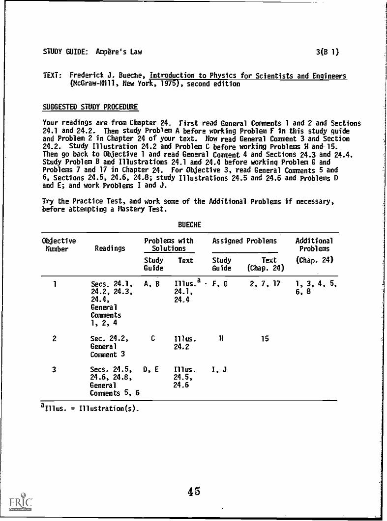
Your readings are from Chapter 24. First read General Comments 1 and 2 and Sections24.1 and 24.2. Then study Problem A before working Problem F in this study guideand Problem 2 in Chapter 24 of your text. How read General Comment 3 and Section24.2. Study Illustration 24.2 and Problem C before working Problems H and 15.Then go back to Objective 1 and read General Comment 4 and Sections 24.3 and 24.4.Study Problem 8 and Illustrations 24.1 and 24.4 before working Problem G andProblems 7 and 17 in Chapter 24. For Objective 3, read General Comments 5 and6, Sections 24.5, 24.6, 24.8; study Illustrations 24.5 and 24.6 and Problems Dand E; and work Problems I and J.
Try the Practice Test, and work some of the Additional Problems if necessary,before attempting a Mastery Test.
BUECHE
Objective Problems with Assigned Problems AdditionalNumber Readings Solutions Problems
Study Text Study Text (Chap. 24)Guide Guide (Chap. 24)
1 Secs. 24.1, A, B Illus.a
F, G 2, 7, 17 1, 3, 4, 5,24.2, 24.3, 24.1, 6, 824.4, 24.4GeneralComments1, 2, 4
2 Sec. 24.2, C Illus. H 15General 24.2Comment 3
3 Secs. 24.5, D, E Illus. I, J24.6, 24.8, 24.5,
General 24.6Comments 5, 6
aIllus. g Illustration(s).

STUDY GUIDE: Amptress Law 3(HR 1)
TEXT: David Halliday and Robert Resnick, Fundamentals of Physics (Wiley, NewYork, 1970; revised printing, 1974)
SUGGESTED STUDY PROCEDURE
Your readings are all from Chapter 30. First read General Comments 1 and 2 andSections 30-1 and 30-2. Then study Problem A and work Problem F in this studyguide, and Problems 1 and 23 in Chapter 30. Next read General Comment 3 andSections 30-3 and 30-4, study Problem C, and work Problems H and 18. Return toObjective 1, reading General Comment 4 and Sections 30-3 and 30-5, studyingProblem 8 and Examples 1 through 4 in Chapter 30, before working Problems t and27. Then read General Comments 5 and 6, and Section 30-6, excluding Example 5.Study Problems D and E before working Problems I, J. and 33.
Take the Practice Test, and work some Additional Problems if necessary, beforeattempting a Mastery Test.
HALLIDAY AND RESNICK
Objective Problems with Assigned Problems AdditionalNumber Readings Solutions Problems
Study Text Study Text (Chap. 30)Guide Guide (Chap. 30)
1 Secs. 30-1, A, B Ex.a
F, G 1, 23, 27 4, 5, 15, 19,30-2, 30-3, 1, 2, 21, 22, 2330-5, General 3, 4Comments I,2, 4
2 Secs. 30-3, C H 18 16, 17, 24, -25
30-4, GeneralComment 3
3 Sec. 30-6, D, E I, J 33 29, 30, 34,
General 35(a)
Comments5, 6
. = Example(s).
46

STUDY GUIDE: Ampere's Law 3(S21)
TEXT: Francis Weston Sears and Mark W. Zemanskv, University Physics (Addison-Wesley, Reading, mass., 1970), fourth edition
SUGGESTED STUDY PROCEDURE
The learning objectives cover the material in the reverse order of your text.You may want to skim Chapter 32 before following this study procedure in detail.(Note: Your text changes notation from 4uk- to uo in Section 32-6.)
For Objective 1, read General Comments 1 and 2 and Section 32-6. Then studyProblem A and work Problems F and 32-3. Next read General Comment 3 and Section32-4, study Problem C, and work Problems H and 32-11. Return to Objective 1,reading General Comment 4, and Section 32-7, studying Problem B, and workingProblems G and 32-17. Next master Objective 3 by reading General Comments 5 and6 and Section 32-2, studying Problems 0 and E, and working Problems I, J, 32-1,and 32-15.
Take the Practice Test, and work some Additional Problems if necessary, beforeattempting a Mastery Test.
SEARS AND ZEMANSKY
ObjectiveNumber Readings
Problems withSolutions
Assigned Problems AdditionalProblems
Study Guide StudyGuide
Text
1 Secs. 32-6, A, R F, 4 32-3, 32-2, 32-4,32-7, 32-17 32-6, 32-18,General 32-1qComments 1,2, 4
2 Sec. 32-4, C H 32-11 32-7, 32-9,General 32-1(1
Comment 3
3 Sec. 32-2, D, E I, J 32-1,General 32-15Comments5, 6
47
STUDY GUIDE: Ampere's Law 3(WS 1)
TEXT: Richard T. Weidner and Robert L. Sells, Elementary Classical Physics(Allyn and Bacon, Boston, 1973), second edition, 1,0 2
SUGGESTED STUDY PROCEDURE
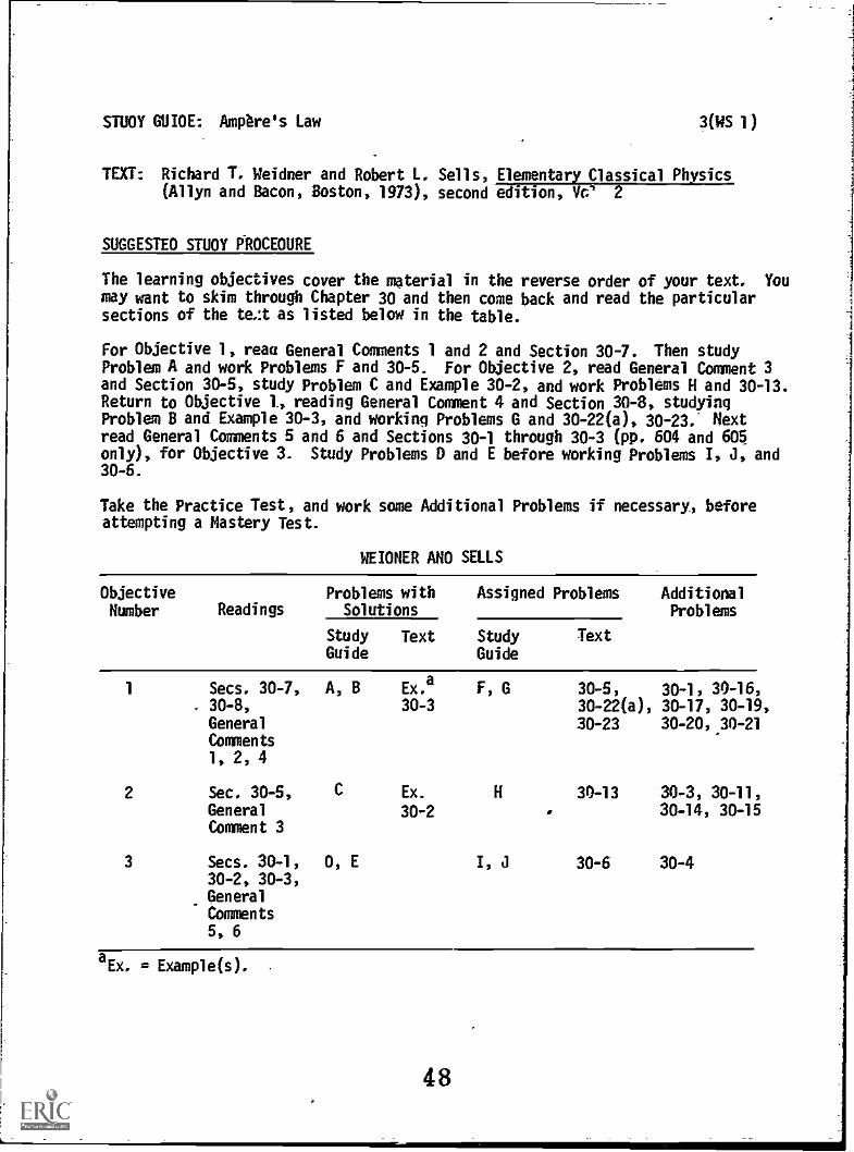
The learning objectives cover the material in the reverse order of your text. Youmay want to skim through Chapter 30 and then come back and read the particularsections of the te.:t as listed below in the table.
For Objective 1, reaa General Comments 1 and 2 and Section 30-7. Then studyProblem A and work Problems F and 30-5. For Objective 2, read General Comment 3and Section 30-5, study Problem C and Example 30-2, and work Problems H and 30-13.Return to Objective 1, reading General Comment 4 and Section 30-8, studyingProblem B and Example 30-3, and working Problems G and 30-22(a), 30-23. Nextread General Comments 5 and 6 and Sections 30-1 through 30-3 (pp. 604 and 6D5only), for Objective 3. Study Problems D and E before working Problems I, J, and30-6.
Take the Practice Test, and work some Additional Problems if necessary, beforeattempting a Mastery Test.
WEIDNER AND SELLS
ObjectiveNumber Readings
Problems withSolutions
Assigned Problems AdditionalProblems
StudyGuide
Text StudyGuide
Text
1 Secs. 30-7, A, B Ex.a F, G 30-5, 30-1, 30-16,, 30-8, 30-3 30-22(a), 30-17, 30-19,General 30-23 30-20,.30-21Comments1, 2, 4
2 Sec. 3D-5, C Ex. H 30-13 30-3, 30-11,General 30-2 . 30-14, 30-15Comment 3
3 Secs. 30-1, D, E I, J 30-6 30-430-2, 30-3,GeneralComments5, 6
. = Example(s).
48

STUDY GUIDE: Ampere's Law.1
GENERAL COMMENTS
1. Comparison of Ampere's Law and the Biot-Savart Law
The examples of the long wire, long solenoid, and toroid make very good iliustrationsof the use of Ampere's law. If you learn Ampere's law well , you will not needto memorize thE expressions for B in these three cases (which are of some importancein themselves) - you will always be able to derive them! (Note that the longsolenoid is the limiting case of a toroid as the radius approaches infinity.)
Ampere's law is completely general for steady currents, and can be used to calculatethe magnetic field in certain symmetric situations in much the same way that Gauss'law can be used in electrostatics. However, many cases (e.g., the circular loop)cannot be handled mith Ampere's law, since one must have a sufficiently simplesituation so that B is constant and can be removed from the integral sign. Forthe circular loop this becomes very impractical. Therefore, we go to the Biot-Savart law for a more general approach. The Biot-Savart law, as stated, representsthe magnetic field in terms of contributions from infinitesimal elements composingthe current circuit. Ampere's law is still true in these cases - it just does notgive any calculational help.
Note that Ampere's law and the Biot-Savart law are not independent of one another.Ampere's law can be derived from the Biot-Savart law and therefore does not containmore information than the Biot-Savart law. The Biot-Savart law is just a moregeneral statement.
2. Straight Wires and Paths
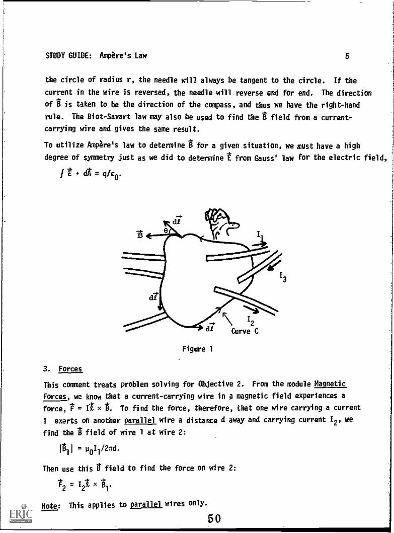
The main thrust of Objective 1 is to familiarize oneself with Ampere's law:
dt = uoI.
On the right side of this equation, I is the net current passing through the area
enclosed by the path of integration. In Figure 1 the net current through the area
bounded by the curve C is I1 + 12 + 13. The positive direction of the current
through the area can be obtained by a right-hand rule - the fingers of the right
hand curling in the direction of dl around the curve C and the thumb pointing in
the positive direction of the current:
#t dt = p0(11 + 12 + 13).
For an area pierced by no current, the line integral around the closed path is zero.
How do we know that the I field from a current in a long straight wire is circular
around the wire? Since the wire looks the same from one side as from another, the
magnitude of at a point near the wire should remain unchanged as the wire is
rotated. Thus 01 is constant on a.circle of radius r centered on the axis of the
wire. But what about the direction of 4? If we take a compass and move it around:
49
STUDY GUIDE: Ampere's Law $
the circle of radius r, the needle will always be tangent to the circle. If the
current in the wire is reversed, the needle will reverse end for end. The direction
of g is taken to be the direction of the compass, and thus we have the right-hand
rule. The Biot-Savart law may also be used to find the g field from a current-
carrying wire and gives the same result.
To utilize Ampere's law to determine g for a given situation, we must have a high
degree of symmetry just as we did to determine t from Gauss' law for the electric field,
t = q/c0'
Figure 1
3. Forces
This comment treats problem solving for Objective 2. From the module Magnetic
Forces, we know that a current-carrying wire in a magnetic field experiences a
force, t = It x To find the force, therefore, that one wire carrying a current
I exerts on another parallel wire a distance d away and carrying current 12, we
find the g field of wire 1 at wire 2:
= poI1/27rd.
Then use this g field to find the force on wire 2:
1.2 = I2 x
Note: This applies to parallel, wires only.
50
STUDY GUIDE: Ampere's Law 6
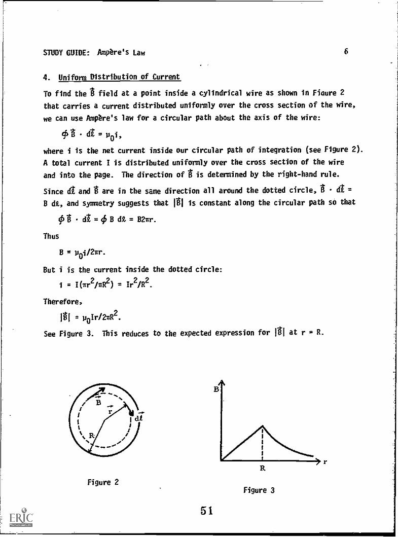
4. Uniform Distribution of Current
To find the field at a point inside a cylindrical wire as shown in Fiaure 2
that carries a current distributed uniformly over the cross section of the wire,
we can use Ampere's law for a circular path about the axis of the wire:
ejSt di= uoi,
where i is the net current inside our circular path of integration (see Figure 2).
A total current I is distributed uniformly over the cross section of the wire
and into the page. The direction of t is determined by the right-hand rule.
Since dt and I are in the same direction all around the dotted circle, t dt =
B dl, and symmetry suggests that M is constant along the circular path so that
Ot dt = B dZ = 82nr.
Thus
B = poi/2ur.
But i is the current inside the dotted circle:
/(i11.2116t2) /r2/R2.
Therefore,
= poIr/2yR2.
See Figure 3. This reduces to the expected expression for 1A1 at r = R.
Figure 2
51
R
Figure 3

STUDY GUIDE: Ampere's Law 7
5. Current Elements
In electrostatics the fundamental law telling us how to calculate the electric
field caused by an element of charge (a point charge) is Coulomb's law. The
corresponding law for magnetic fields is called the Biot-Savart Law. The funda-
mental source of the magnetic field is a current element, which we can think of
as a small length of wire di carrying a current I in the direction of dt. The
Biot-Savart law says that the magnetic field 4 at a distance 1: caused by this
incremental length is given by
og POI di x POI di x
r2 4w
r3
where p0
is a constant (p0
= 4x x l0-7 if the units for 8, I, and r are teslas,
amperes, and meters, respectively), and r is a unit vector in the direction of
r. See Figure 4.
Notice that the Biot-Savart law is an inverse-square law. It is more complicated
than Coulomb's and the gravitational laws, however, because of the cross product:
d points not along 1: but in a direction perPendicular to both 1: and dt.
Observe that the dL that occurs in Amoere's law has quite a different significance
from the d in the Biot-Savart law. In Ampere's law, it is along an imaoinary
path that need bear no relation to the direction of current flow, whereas in
the Biot-Savart law it is along the direction of the current flow in the wire.
52

STUDY GUIDE: Ampere's Law
6. Semicircular Current Loops
The Biot-Savart law gives the magnetic field produced by an infinitesimal current,
as we shall see in Problems D and I. However, no such isolated current element
can exist by itself. There must always be a complete loop of current in any
circuit.
8
The most general case of current-carrying wires involves a detailed integration
of the Biot-Savart law, but there is a special case that requires only the interpre-
tation of a line integral. This is the problem of finding the field at the
center of a circular or semicircular loop of current. Here, the current element
I St is always perpendicular to the position vector ;:
I dt x r = a vector.whose magnitude is Ir dt, in a direction perpendicularto both r and dt.
Since we are finding the field at the center of the loop, the distance r is a
constant and equal to the radius a. Thus,
Jai = (p0I/4=2)(1Z.
In summing up or integrating the contributions from all the significant current
elements, fdt is just the length of the semicircular loop.
PROBLEM SET WITH SOLUTIONS
A(l). Two long straight parallel wires both carry a current of 8.0 A, but inopposite directions as shown in Figure 5. Calculate the magnetic fieldat the indicated point P caused by these currents.
Solution
Divide this problem into two problems, and use Ampere's law in both. The II- field
caused by the lower wire is found by integrating .6 around a circle of radius 2.00 m
that is concentric with the lower wire:
Oil dt = B12ir(2) = p0(8), = 8.0 x 10⁻⁷ T.
According to the right-hand rule, ti at the point of interest is directed out of
the page,
To find thethe contribution from the upper wire, we integrate 12 around a circle
of 4.0 m radius that is concentric with the upper wire. Note that we include W, L
the upper current Oement in the term for enclosed current, because we have divided
53
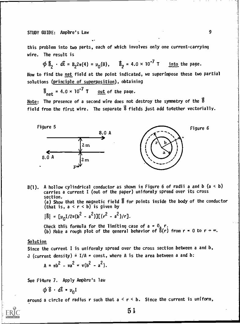
STUDY GUIDE: Ampere's Law 9
this problem into two parts, each of which involves only one current-carrying
wire. The result is
ok A = B2270) = p0(8), = 4.0 x 10⁻⁷ T into the page.
Now to find the net field at the point indicated, we superimpose these two partial
solutions (principle of superposition), obtaining
net4.0 x 10-7 T out of the page.
Note: The presence of a second wire does not destroy the symmetry of the
field from the first wire. The separate fields just add together vectorially.
Figure 5
8.0 A
P.
m
8.0 AFigure 6
B(1). A hollow cylindrical conductor as shown in Figure 6 of radii a and b (a < b)
carries a current I (out of the paper) uniformly spread over its crosssection.(a) Show that the magnetic field for points inside the body of the conductor
(that is, a < r < b) is given by
1ri ,= [poI/274b
2- a2 ))[(r2 - a2 ) /r).
Check this forffiula for the limiting case of a = A r.
(b) Make a rough plot of the general behavior of 8(r) from r = 0 to r to.
Solution
Since the current I is uniformly spread over the cross section between a and b,
(current density) i I/A = const, where A is the area between a and b:
1112 wa2 w(b2 a2).
See Figure 7. Apply Ampere's law
06 dt = poI
around a circle of radius r such that a < r < b. Since the current is uniform,
51
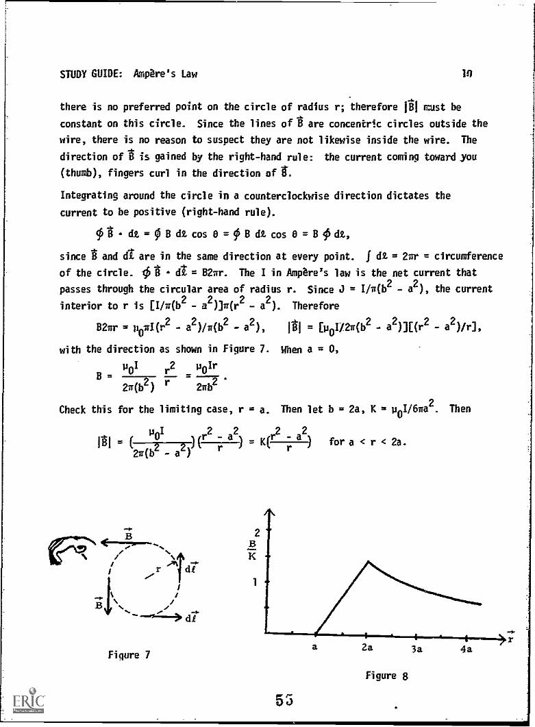
STUDY GUIDE: Ampere's Law 10
there is no preferred point on the circle of radius r; therefore 111 must be
constant on this circle. Since the lines oft are concentric circles outside the
wire, there is no reason to suspect they are not likewise inside the wire. The
direction of t is gained by the right-hand rule: the current coming toward you
(thumb), fingers curl in the direction of 1.
Integrating around the circle in a counterclockwise direction dictates the
current to be positive (right-hand rule).
01 dt = B dt cos 0 = B dt cos 0 = B 4i dt,
since t and d1 are in the same direction at every point. f dt = 2nr = circumference
of the circle. t t dt = B2nr. The I in Ampere's law is the net current that
passes through the circular area of radius r. Since J = I/n(b2 - a2), the current
interior to r is [I/n(b2 - a2Dr(r
2- a
2). Therefore
B2ur = p0wl(r2
- a2)/w(b
2- a
2), [UoI/21r(b
2- a
2)][(r
2- a
2)/r],
with the direction as shown in Figure 7. When a = 0,
unI r2 unIrg = L-. =
r 2111)2
Check this for the limiting case, r = a. Then let b = 2a, K = u01/6wa2. Then
2 2 2 2114
21roz a2) r
r - a ) afor a < r < 2a.
r di
dr
Figure 7
2
Figure 8

STUDY GUIDE: Ampbre's Law 11
Figure 8 is a graph for b = 2a, which is not required for this problem. You
could have chosen any other value for b as long as the point b is somewhat near
the center of the graph so that the curve of '4 versus r is easily seen.
C(2). In Problem A, find the force per unit length on the bottom wire.
Solution
The t field caused by the top wire is given by dl = p01, as we found inProblem A:
81 = -(p011/21rd)k
it the location of the bottom wire. The force on the bottom wire is given by2 = 12t x 131:
A A= (.422.0 x Up011/2xd)(-k)3 = -(11I2u0/2ad)j.
Thus the force per unit length is
l/1 = -(1112u04)/2ad = -6.4 x 10-61 n/m repulsion.
m= 8A
12- SA
Figure 9k
D(3). Imagine a current element I a in which the current lies in the xv plane,and is directed to the right parallel to the x axis. What is the magneticfield at the origin if the current increment is located:(a) at the point (x, y, z) = (0, a, 0) m?(b) at the point (a, a, 0) m?(c) at the point (a, 0, 0) m?
Solution
(a) See Figure 10. r = -j.
dg (-j)1)_ (_0.
a2 41a4
56
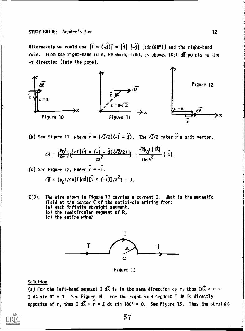
STUDY GUIDE: Ampere's Law 12
Alternately we could use ji x (-3)1 = III 1-31 [sin(901] and the right-hand
rule. From the right-hand rule, we would find, as above, that d points in the
-z direction (into the page).
r = a
Figure 10
;7>g-/r=a47
feFigure 11
x
(b) See Figure 110 where r = (i2 /2)( -i - 3). The 472 makes r a unit vector.
POI(
^
x (-i
^
j)(V7/2)])/2-14
-I1dt1
(-k).7-)
2a2 Mae
d.
(c) See Figure 12, where r =
d = (u0I/40(Id11[i x (-i)] ia2) = 0.
E(3). The wire shown in Figure 13 carries a current I. What is the magneticfield at the center C of the semicircle arising from:(a) each infinite straight segment,(b) the semicircular segment of R,(c) the entire wire?
I
Solution
(a) For the left-hand
I dt sin 0° = 0. See
opposite of r, thus I
1
C
Figure 13
segment I d is in the same direction as r,
Figure 14. For the right-hand segment I d2
d1 x r = dt sin 180° = 0. See Figure 15.
57
thus kit x r =
is directly
Thus the straight
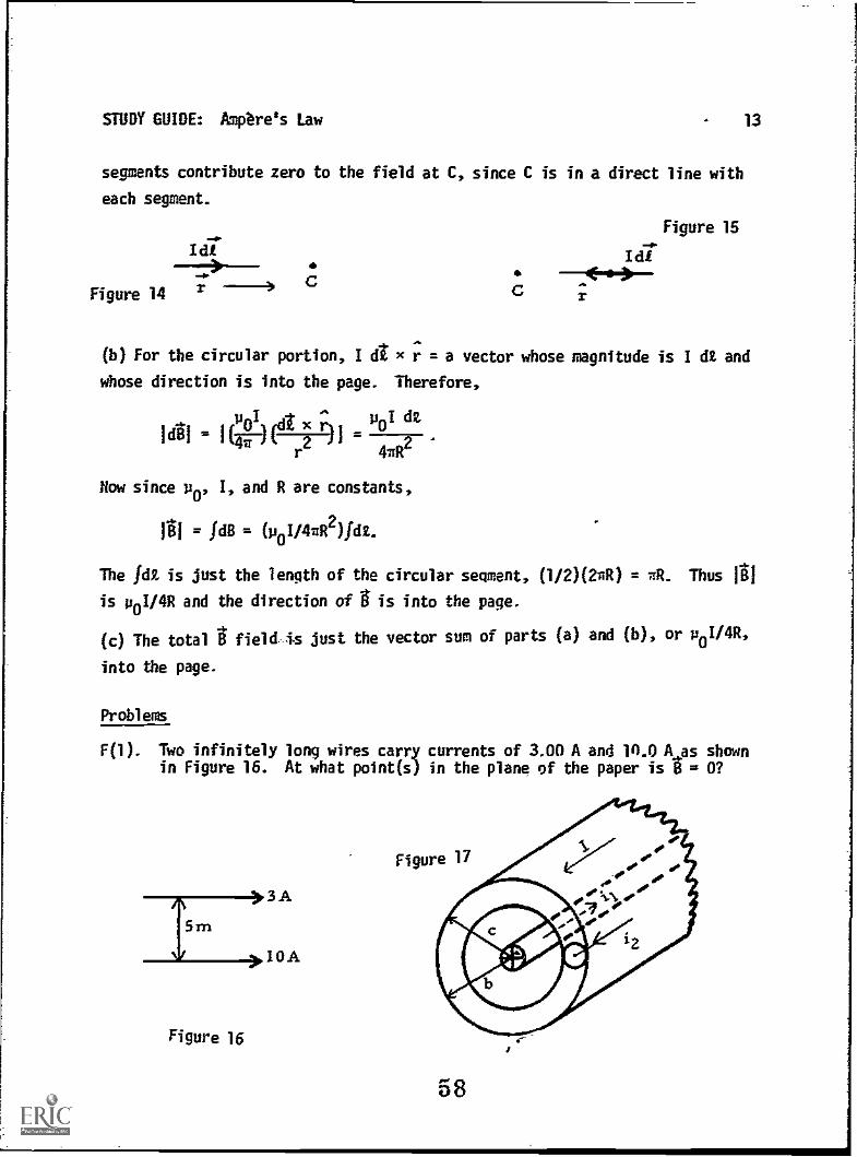
STUDY GUIDE: Ampere's Law 13
segments contribute zero to the field at C, since C is in a direct line with
each segment.
Idl
Figure 14 rC C
..<-10-)
Figure 1S
(b) For the circular portion, Idtxr=avector whose magnitude is Id/ and
whose direction is into the page. Therefore,
uoll 4 voI
141 1(iF)(1FL11 2
e
4aR
Row since u0, I, and R are constants,
01 = fa = (p0i/442)1AI.
The la is just the length of the circular segment, (1/2)(24) = TM. Thus 01
is v0I/4R and the direction of g is into the page.
(c) The total B field. Is just the vector sum of parts (a) and (b), or v0I/4R,
into the page.
Problems
F(l). Two infinitely long wires carry currents of 3.01) A and 10.0 A as shownin Figure 16. At what point(s) in the plane of the paper is B = 0?
3A
10A
Figure 16
58
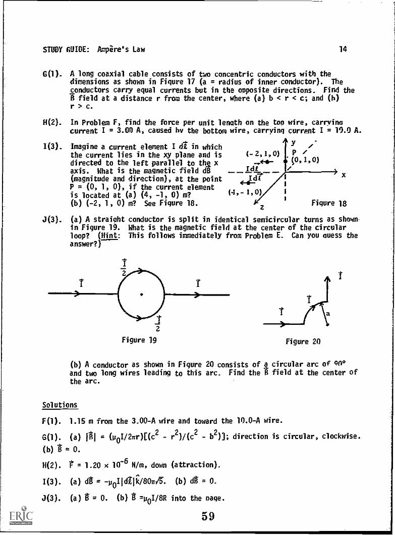
STUDY GUIDE: Ampire's Law 14
G(1). A long coaxial cable consists ofdimensions as shown in Figure 17conductors carry equal currents bfield at a distance r from the
r > c.
two concentric conductors with the(a = radius of inner conductor). Theut in the opposite directions. Find thecenter, where (a) b < r < c; and (b)
H(2). In Problem F, find the force per unit length on the too wire, carrvinacurrent I = 3.00 A, caused by the bottom wire, carrying current I = 10.04A.
1(3). Imagine a current element I d in whichthe current lies in the xy plane and isdirected to the left parallel to thg.xaxis. What is the magnetic field dB(magnitude and direction), at the pointP = (0, 1, 0), if the current elementis located at (a) (4, -1, 0) m? (4,-
(b) (-2, 1, 0) m? See Figure 18.
(-2,1,0) P zt0,1,0)
IdEx
Figure 18
J(3). (a) A straight conductor is split in identical semicircular turns as shownin Figure 19. What is the magnetic field at the center of the circularloop? (Hint: This follows immediately from Problem E. Can you Guess the
answer?)
r
Figure 20
(b) A conductor as shown in Figure 20 consists of k circular arc of 441*and two long wires leading to this arc. Find the B field at the center of
the arc.
Solutions
F(1). 1.15 m from the 3.00-A wire and toward the 10.0-A wire.
G(1). (a) 1g1 = (p0I/2wr)[(c2 - r2)/(c2 b2)]; direction is circular, clockwise.
(b) =0.
H(2). 1 = 1.20 x 1076 N/m, down (attraction).
I(3). (a) dg = - p0I1dZJk /80sr1 . (b) d = 0.
J(3). (a) g= 0. (b) g =poi/8R into the Page.
59

STUDY GUIDE: Ampere's Lew 15
PRACTICE TEST
1. A long, straight hollow (inner radius R, outer radius TO conductor in Figure21 carries a current I (cut of paper) that is uniformly distributed over thecross section. If r measures the position fro the axisof the conductor,deteinine 0 (magnitude and direction) for (a) r = -(R/2)i, (h) r = 2Rj, and(c) r = 50.
Figure 21
2. A thin wire of length L carries a curr *nt 3I,,parallel to the conductor of
Problem 1. The wire is positioned at r = 5Ri from the axis of the hollowconductor. Determine the force (magnitude and direction) on this wire.
3. Imagine a current element I a in which the current lies in the xy plane andis directed downward and to the right at an angle of 45° to the x axis; i.e.,
= 61/2)tdtl(i - i).
'Mat is the magnetic field d at the origin if the current element is located:
(a) at the point (2, 0, 0)? (b) at (-4, 0, 0)?
-ze/(1.&)3 = P (q) voge-)3 = P (e) :4,14(1117/Iild) = 3 481 'E
'1(11110l/lzOnE)- 7
'E(111101/I°11) (3) '1(1PLZE/IllifE)- (e)
5JBMS14 4Sal 830.32.14
60
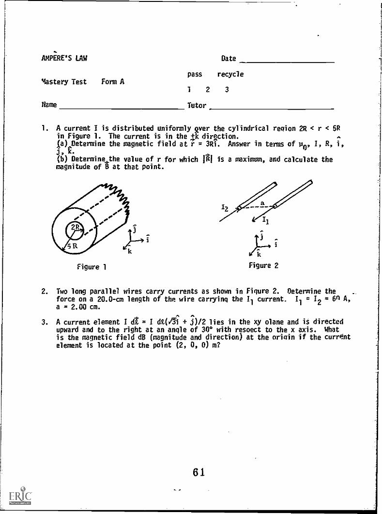
AMPiREIS LAW
Mastery Test Form A
flame
Date
pass recycle
1 2 3
Tutor
1. A current I is distributed uniformly aver the cylindrical region 2R < r <in Figure 1. The current is in the 4.-Ic dir2ction.la) Determine the magnetic field at r = 3Ri. Answer in terms of ji0, I, R,it E-a)) Determine the value of r for which 114 is a maximum, and calculate themagnitude of at that point.
Figure 1
T--
Figure 2
2. Two long parallel wires carry currents as shown in Figure 2. Determine theforce on a 20.0-cm length of the wire carrying the Il current
1= 1
2= 6n A,
a = 2.00 cm.
3. A current element I d1 = I dt(1iupward and to the right at an angleis the magnetic field dB (magnitudeelement is located at the point (2,
j)/2 lies in the xy plane and is directedof 300 with respect to the x axis. Whatand direction) at the oriain if the current0, 0) m?
61
:1
1
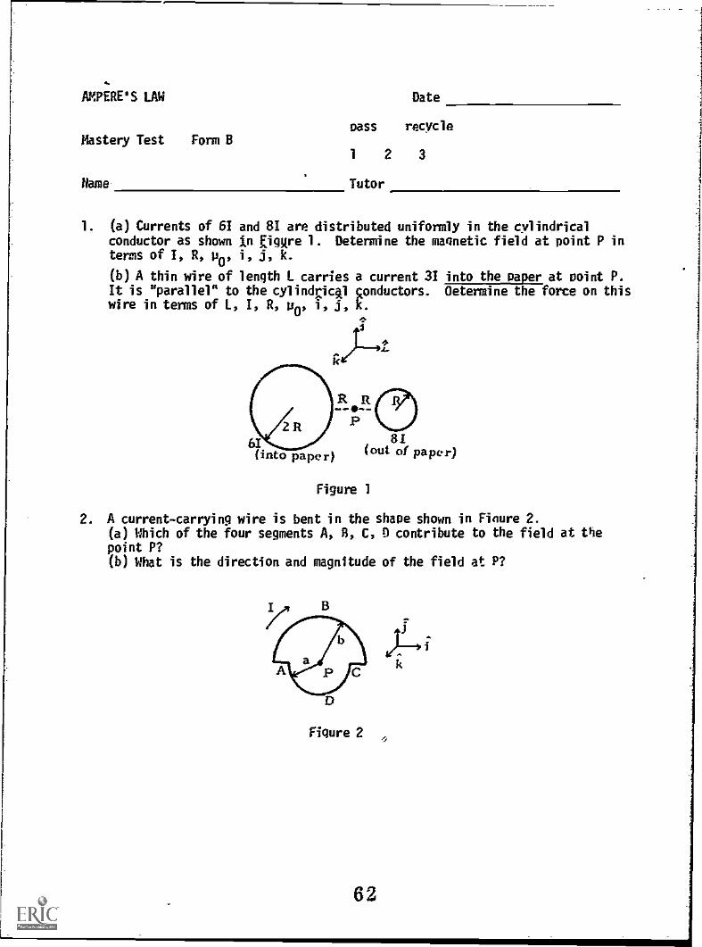
AMPERE'S LAW Date
pass recycleMastery Test Form B
1 2 3
Mame- Tutor
1. (a) Currents of 61 and 81 are distributed uniformly in the cylindricalconductor as shown in Eiglire 1. Determine the magnetic field at point P interms of 1, R, p0, i, j, k.
(b) A thin wire of length L carries a current 31 into the Paper at Point P.It is "parallel" to the cylindrickl conductors. Determine the force on thiswire in terms of I., I, R, up, i, j, k.
3
IZ
R R
61 81(into paper) (out of paper)
Figure 1
2. A current-carrying wire is bent in the shape shown in Finure 2.(a) Which of the four segments A, 8, C, D contribute to the field at thepoint P?(b) What is the direction and magnitude of the field at P?
Figure 2
62

AMPERE'S LAW
Mastery Test Form C
Name
Date
pass recycle
1 2 3
Tutor
1. (a) A current of 31 is distributed uniformly in the cylindrical regionR < r < 2R as shown in Figure 1. A current of 21 is uniformly distributedin a cylindrical conductor of radius R as shown. Determine the magnetic fieldat points 0 and P in terms of I, R, and constants.(b) A thin wire of length L carries a current 21 into the paper at point P.It is "parallel" to the two cylintical conductors. Determine the force onthis wire in terms of 1, R, L, i, j, k, and other constants.
tLis
3It
P
31(out of paper)
Figure 1
21(into paper)
2. Imagine a current element,I dr in which the current lies in the xy planeand is directed upward and to the right at an angle of 53° to the x axis, i.e.,
dt = d2.(0.6i + 0.8j).
What is the magnetic field d (magnitude and direction) at the origin if thecurrent element is located at the point (2, 0, 0) m?

AMPERE'S LAW Date
pass' recycleMastery Test Form D
1 2 3
Name Tutor
1. A solenoid consists of 500 turns of wire wound around a cylindrical shell1.00 cm in radius and 10.0 cm long. What is the magnetic field at the centerof the solenoid when a current of 6.0 A is sent through the solenoid?
2. Two wires carrying the same current I are bent into semicircles as shown inFigure 1. The ends are then overlapped closely but not touching to form acircle of radius R, as in Figure 2. What is the magnetic field at the centerof the circle (direction and magnitude)?
ti t2
112
Figure 1
12
'1(44
2
Figure 2
3. Two long wires carry currents of 3.00 A and 10.0 A, as in Figure 3. Whatis the force per unit length on the bottom wire carrying 10.0 A? (Thewires are separated a distance of 5.0 m.)
Figure 3
61

AMPERE'S LAW
MASTERY TEST GRADING KEY - Form A
A-1
1. What To Look For: (a) Do they start off from Ampere's law? What is i?Fraction of I enclosed by circle of radius 3R. How do you determine direction?(Apply right-hand rule, have student do it.) (b) How do you know is maximumat r = 5R? (See Figure 3D.)
Solution: (a) = 3Ri) = ? g d1 = poi,
POi Iv (3R)2(1r )(
- (2R)22
I08-)21R
2(5R)
2)- (2R)
= (5pei/4214311)]i = (5p0I/12671R]i.
(b) See Figure 30. g is maximum at r = 5R. For (2R < r < 5R),
FA' = p0i(r2 4R2)/2vr(21R2). For 5R < r, = poi/211r. At r = 5R,
= poi/10A.
R 2R 3R 4R SR
Figure
2. What To Look For:
Solution: From 1
= it x
= (7.2 x 10⁻³)i
Figure 31
Are the directions for g from I2
correct?
g d = poi, g at caused by 12 equals -(p0i2/2va)j.
/** POI POI2t (471 x 10-7)(60)2(fl.200)i,
12 (Ilik) x (-11.2.71) (17-)(i) 21T(0.0200)
N.
3. What To Look For: Do they start with the Biot-Savart law?
Solution: See Figure 31.^ ^ ^
p I dt x r poi dt( /i x p)=
44(22)r = -I, Irl = 2, a = (poi tit/32v)k.

AMPERE'S LAW R-1
MASTERY TEST GRADING KEY - Form B
1. What To Look For: (a) Did they start from Ampere's law and get poi/2nr?What is i? What is r? (b) Can they evaluate the cross product correctly?
Solution: (a) Add t fields from each wire at P:
f = P01, GI = Cp0(60/211(3R)1(-1) = -(p0I/nR)i,
8I = (p0(8I)/2w(20](4) = -(2p0I/nR)i,total -(3110I/PR)i*
(b) = I1 x = 3IL(-k) x (-3p0indOi = -(91.I2P0taR)I.
2. What To Look For: (b) Do they start with Biot-Savart law or know where
= p0I/4R comes from?
Solution: (a) Only 8, D contribute. A and C have d x r = O.
(b) For a circle d .(p0I dl x r)/4rr2.
lai = (Poi d/)/0r2 (r = radius).
For a half-circle:
P I 1 POI0-07(27tr) = 447-jk.Or .
Therefore
A
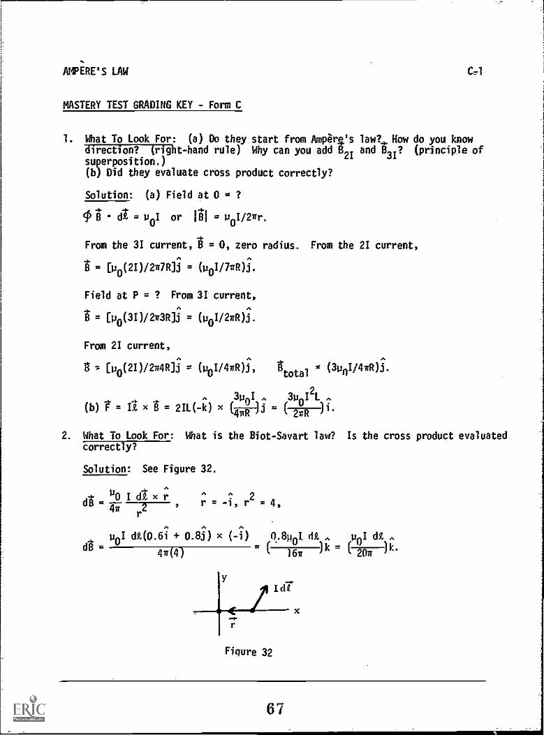
AMPERE'S LAW
MASTERY TEST GRADING KEY - Form C
1. What To Look For: (a) Do they start from Ampere's law? How do you knowdirection? (right-hand rule) Why can you add 821 and 83/? (principle ofsuperposition.)(b) Did they evaluate cross product correctly?
Solution: (a) Field at 0 = ?
tl dt = u0I or NI = u
0I/2nr.
From the 31 current, i = 0, zero radius. From the 21 current,
= [4(20/2g7R]j = (p0I/714t)i
Field at P = ? From 31 current,
= [p0(30/2g3R]i = (p0I/2gR)i.
From 21 current,
t [4(20/27:4R]i = (p0I/4A)i,total
= (3pnI/4740i.
3p 0I A 3p0I21 A
(b) = ft x = 211( -k) x (Fpi
2. What To Look For: What is the Biot- Savart law? Is the cross product evaluatedcorrectly?
Solution: See Figure 32.
2r = -1, r = 4,
d
po di(om 0.8;) x ( -1)
4.(4)
11.8Pot dt A uoI dt A
16g)k )k.
Figure 32
67
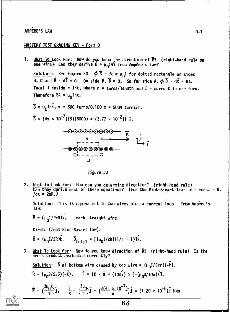
AMPiRE'S LAW
MASTERY TEST GRADING KEY - Form D
0-1
1. What To Look For: How do ygp know the direction of 1? (right-hand rule onone wire) Can they derive B = poIni from Ampare's law?
Solution: See Fiqure 33. 4:P1 (12 = poI for dotted rectangle on sides
D, C and d = O. On side B, B = O. So for side A, 0-6 (it= Bt.
Total I inside = Int, where n = turns /length and I = current in one turn.
Therefore Bt = point.
= poIni,n = 500 turns/0.100 m = 5000 turns/m.
= (4a x 10-7)(6)(5000) = (3.77 x 10⁻²)i T.
0 0 0 0 0 0 0 0 0
-.A
D C
Figure 33
13
2. What To Look For: How can you determine direction? (right-hand rule)Can they derive each of these equati'ns? (For the Eiot-Savart law: r = const = R.fdt = 2a11.)
Solution: This is equivalent to two wires plus a current loop. From Ampere'slaw:
= (p0i/2141)k, each straight wire.
Circle (from Biot-Savart law):
= (1oi/2R)total
[(p0I/2R)(1/T 1)1k.
3. What To Look For: How do you know direction of V ( right -hand rule) Is thecross product evaluated correctly?
Solution: .6 at bottom wire caused by top wire = (1411/2ar)(4
(103/2a5)(-i), = It x (101a) x (443/10.)ki,
= t
310t (3(47r x 10-7)-^jj (1.20 x 10⁻⁶)i N/m.

Module
STUDY GUIDE
FARADAY'S LAW
INTRODUCTION
Consider the electric light you may be using to read this module by and theinfluence on your life style of the vast amounts of electrical energy producedin the United States. This module treats the fundamental principle that allowsfor the transformation of mechanical energy into electrical energy. The physicallaw that governs the production of electric current is named after its discoverer,Michael Faraday.
PREREQUISITES
Before you begin this module, Location ofyou should be able to: Prerequisite Content
*Calculate scalar products (needed for VectorObjectives 1 through 3 of this module) Multiplication Module
*Use Ohm's law to determine the current, Ohm's Lawknowing the resistance and voltage (needed Modulefor Objective 3 of this module)
*Given the current direction, determine the Ampere's Lawdirection of the magnetic field; or given Modulethe direction of the magnetic field,determine the direction of the sourcecurrent (needed for Objectives 2 through4 of this module)
LEARNING OBJECTIVES
After you have mastered the content of this module, you will be able to:
1. Faraday's law - Write the equation for Faraday's law in the form & = -dip/dtand define all terms with correct units.
2. Magnetic flux - Determine the magnetic flux or the time rate of change ofthe magnetic flux for an area in a magnetic field.
3. Application of Faraday's law - Determine, using Faraday's law, the inducedcurrent and/or voltage for a situation involving either (a) a stationarycircuit in a time-varying magnetic field, or (b) a conductor moving in amaanetic field.
69

STUDY GUIDE: Faraday's Law 2
4. Lenz's law - Apply Lenz's law to a situation as listed in Objective 3 todetermine the direction of the induced current and explain your reasoning.
GENERAL COMMENTS
1. Faraday's Law
In this module you will be held responsible for the following form of Faraday'slaw:
E = -deft,
where the magnetic flux is
= g.
The induced emf is produced by the time rate of change of the magnetic flux. Thisis the fundamental principle of the generation of electrical energy. This form ofFaraday's law allows us to calculate the induced emf caused by a time-varyingmagnetic field or a moving circuit in a magnetic field.
What is the induced emf? The voltage induced in a circuit is produced by anelectric field (force per unit charge) acting over the current path (circuit):
E= dt
This is the work required to move a unit charge around a complete circuit. In
this case, the force that produces the electric field is magnetic in origin andtherefore produces a nonconservative force or electric field En. The integralof a nonconservative force per unit charge over a complete path is not equal tozero but, rather, is equal to the work done per unit charge, which is the inducedemf. Mechanical work is required to produce a current in a magnetic field. Theoperation of the Betatron is based on this equation.
The complete form of Faraday's Yaw is
ftn
dt = - d¢ /dt,
where the left-hand side is the induced emf and the right-hand side tells you howto calculate the induced emf. This form suggested that there is a very intimaterelationship between electric and magnetic fields.
Why have we chosen to test you on the first listed form of Faraday's law?In a certain sense, the decision is arbitrary because a relativistic treatmentof electric and magnetic fields shows that they are merely different perspectivesof the same quantity, which depends on the velocity of the observer. The reasonfor using the form 8 = -,10/dt is that it is more useful for a course at thislevel. A future module Inductance is based on this form of Faraday's law. Thecomplete form of Faraday's law is very powerful, but its usefulness is morereadily seen in an advanced course in electricity and magnetism.
70

STUDY GUIDE: Faraday's Law 3
2. Lenz's Law
The minus sign in Faraday's law can best be explained by the use of Lenz's law.Lenz's law, or the minus sign in Faraday's law, is merely a consequence of theconservation of energy. It tells us that we must do mechanical work to rotatea loop of wire in a magnetic field to produce electrical energy.
Objective 4 requires that you explain your reasoning for determining the directionof the induced current. It is suggested that you answer this question in termsof the first cause; for example, rotating a coil in a magnetic field requires atorque, and your answer should be in terms of the direction of the induced currentthat would oppose this rotation.
3. Units
You have experienced the confusion produced by different sets of units, andmagnetic-field units are perhaps the worst. Textbooks use a variety of units,but this module (Problem Set, Practice Test, and Mastery Tests) will use webers(Wb) for magnetic flux, and teslas (1 T = 1 Wb/m2) for magnetic fields. From
Faraday's law it is possible to show that one volt = one weber per second.You may wish to prove this for yourself.
71
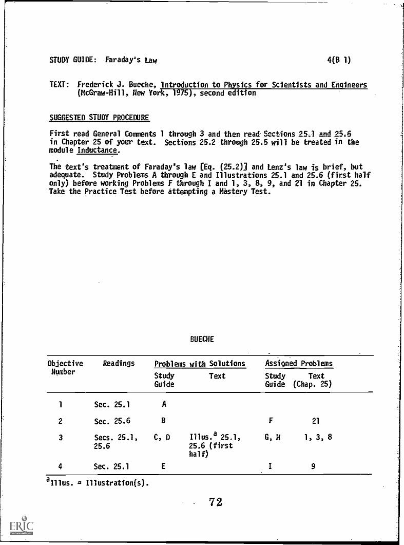
STUDY GUIDE: Faraday's Law 4(B 1)
TEXT: Frederick J. Bueche, 'Introduction to Physics for Scientists and Engineers(McGraw-Hill, Hew York, 1975), second edition
SUGGESTED STUDY PROCEDURE
First read General Comments 1 through 3 and then read Sections 25.1 and 25.6in Chapter 25 of your text. Sections 25.2 through 25.5 will be treated in themodule Inductance.
The text's treatment of Faraday's law [Eq. (25.2)] and Lenz's law is brief, butadequate. Study Problems A through E and Illustrations 25.1 and 25.6 (first halfonly) before working Problems F through I and 1, 3, 8, 9, and 21 in Chapter 25.Take the Practice Test before attempting a Mastery Test.
BUECHE
ObjectiveHumber
Readings Problems with Solutions Assigned Problems
Study Text Study TextGuide Guide (Chap. 25)
1 Sec. 25.1 A
2 Sec. 25.6 6 F 21
3 Secs. 25.1, C, D Illus.a25.1, G, H 1, 3, 8
25.6 25.6 (firsthalf)
4 Sec. 25.1 E I 9
aIllus. = Illustration(s).
72
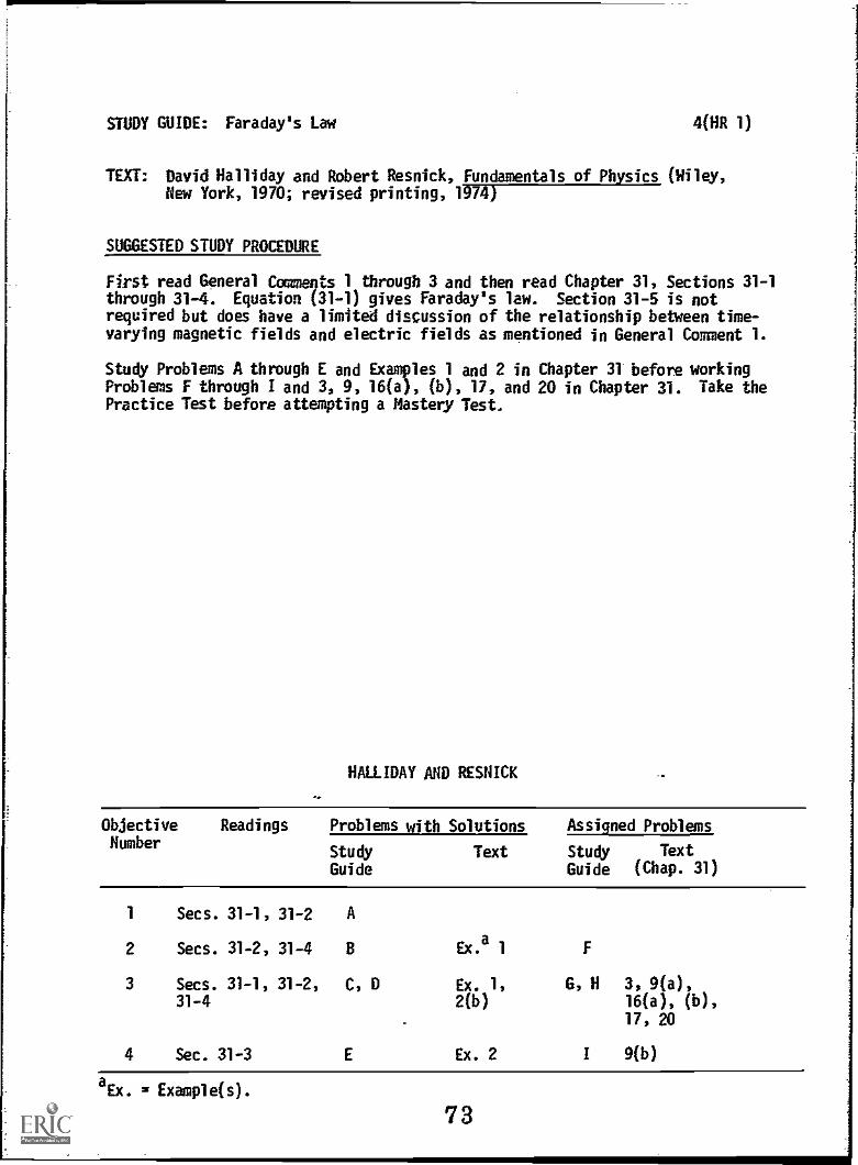
STUDY GUIDE: Faraday's Law 4(HR 1)
TEXT: David Halliday and Robert Resnick, Fundamentals of Physics (Wiley,New York, 1970; revised printing, 1974)
SUGGESTED STUDY PROCEDURE
First read General Comments 1 through 3 and then read Chapter 31, Sections 31-1through 31-4. Equation (31-1) gives Faraday's law. Section 31-5 is notrequired but does have a limited discussion of the relationship between time-varying magnetic fields and electric fields as mentioned in General Comment 1.
Study Problems A through E and Examples 1 and 2 in Chapter 31 before workingProblems F through I and 3, 9, 16(a), (b), 17, and 20 in Chapter 31. Take thePractice Test before attempting a Mastery Test.
HALLIDAY AND RESNICK
Objective Readings Problems with Solutions Assigned ProblemsNumber
Study Text Study Text
Guide Guide (Chap. 31)
1 Secs. 31-1, 31-2 A
2 Secs. 31-2, 31-4 8 Ex.a 1
3 Secs. 31-1, 31-2, C, D Ex. 1, G, H 3, 9(a),31-4 2(b) 16(a), (b),
17, 20
4 Sec. 31-3 E Ex. 2 I 9(b)
aEx. = Example(s).
73
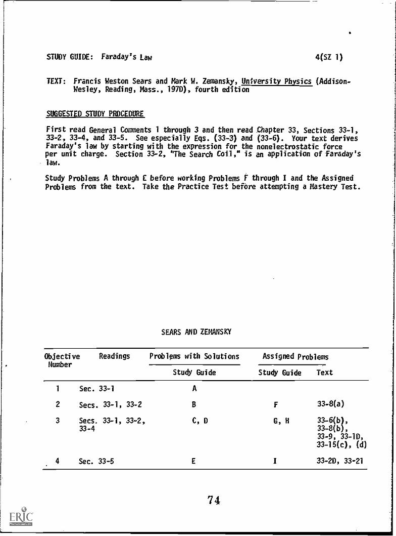
STUDY GUIDE: Faraday's Law 4(SZ 1)
TEXT: Francis Weston Sears and Mark W. Zemansky, University Physics (Addison-Wesley, Reading, Mass., 1970), fourth edition
SUGGESTED STUDY PROCEDURE
First read General Comments 1 through 3 and then read Chapter 33, Sections 33-1,33-2, 33-4, and 33-5. See especially Eqs. (33-3) and (33-6). Your text derivesFaraday's law by starting with the expression for the nonelectrostatic forceper unit charge. Section 33-2, "The Search Coil," is an application of Faraday'slaw.
Study Problems A through E before working Problems F through I and the AssignedProblems from the text. Take the Practice Test before attempting a Mastery Test.
SEARS AND ZEMANSKY
Objective Readings Problems with Solutions Assigned ProblemsNumber
Study Guide Stud Guide Text
1 Sec. 33-1 A
2 Secs. 33-1, 33-2 B F 33-8(a)
3 Secs. 33-1, 33-2, C, D G, H 33-6(b),
33-4 33-8(b),33-9, 33-10,33-15(c), (d)
4 Sec. 33-5 E I 33-20, 33-21
74

STUDY GUIDE: Faraday's Law 4(WS I)
TEXT: Richard T. Weidner and Robert L. Sells, Elementary Classical Physics(Allyn and Bacon, Boston, 1973), second edition, Vol. 2
SUGGESTED STUDY PROCEDURE
First read General Comments 1 through 3 and then read Chapter 31, Sections 31-1through 31-4. See especially Eq. (31-5). Although not required, your text doeshave a partial discussion of the relationship between time-varying magneticfields and nonconservative electric fields in Section 31-5 and in particular onp. 632.
Study Example 31-1 and Problems A through E before working Problems F through Iand the Assigned Problems from your text. Take the Practice Test beforeattempting a Mastery Test.
WEIDNER AHD SELLS
Objective Readings Problems with Solutions Assigned Problems
NumberStudy Guide Text Study Guide Text
1 Sec. 31-1
2 Secs. 31-2, 31-3
3 Sec. 31-3
A
B Ex.a 31-1
C, D Ex. 31-1 G, H 31-1(a), 31-2,31-8, 31-10(a),31-12
4 Sec. 31-4 E i 31-5
aEx. = Example(s).
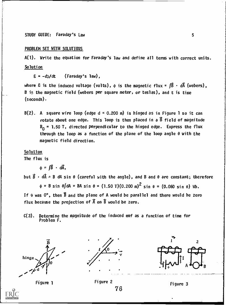
STUDY GUIDE: Faraday's Law
PROBLEM SET WITH SOLUTIONS
A(l). Write the equation for Faraday's law and define all terms with correct units.
Solution
S = -4/dt (Faraday's law) ,
where is the induced voltage (volts), 0 is the magnetic flux = 0 d (webers),
B i$ the magnetic field (webers per square meter, or teslas), and t is time
(seconds).
B(2). A square wire loop (edge d = 0.200 m) is hinged as in Figure 1 so it can
rotate about one edge. This loop is then placed in a I field of magnitude
Bo = 1.50 T, directed perpendicular to the hinged edge. Express the flux
through the loop as a function of the plane of the loop angle 0 with the
magnetic field direction.
Solution
The flux is
0 = dA,
but d = B dA sin 6 (careful with the angle), and B and 6 are constant; therefore
= B sin OfdA = BA sin 0 = (1.50 T)(0.200 m)2 sin 0 = (0.060 sin 6) Wb.
If 6 was 00, then andand the plane of A would be parallel and there would be zero
flux because the projection of A' on t' would be zero.
C(3). Determine the magnitude of the induced emf as a function of time forProblem F.
Figure 1 Figure 2
76
2
Figure 3

STUDY GUIDE: Faraday's Law
Solution
This is a situation of a time-varying magnetic field:
6
= -d /dt.
We are interested in the magnitude of E and will therefore ignore the minus sign:
= 0 a.is a function of time but is uniform in space, therefore
fg BoOet/c,
S = (d/dt)(801.2et/c) 801.2(d/doet/c
or E. = (B0L2/c)et/c.
Check the units and remember that et/c is dimensionless.
D(3). A straight wire, t = 3.00 m long, which is part of a circuit, moves in the
plane of Figure 2 as shown with a velocity if = 10.01 m/s. If the angle 0
is 30° and the magnetic field has a magnitude of B = 0.120 T and is directed
perpendicularly out of the paper, what is the magnitude of the induced emf?
Solution
This is a situation of a moving conductor in a constant magnetic field. The
conductor sweeps out an area per unit time of tv sin 0, therefore (ignoring the
negative sign) Faraday's law is C = dO/dt, where
dt
At-
d--in c Btv sin 0dt
and
E = Btv sin e = (0.120 1)(3.00 m) (10.0 m/s) (1/2) = 1.80 V.
For 0 = 0, the wire would not sweep out an area. If you wish you may check how
reasonable this answer appears in terns of the magnetic force on a moving charge
F = qv+
x g and determine whether 0 = 0 or 0 = 900 would give the greater charge
separation.
E(4). Use Lenz's law to determine the direction of the induced emf in coil 2 inthe -f of lading cases and explain your reasoning (56ETWIF-W----(a) 2 is moved toward 1.(b) The current is decreased in 1.
77
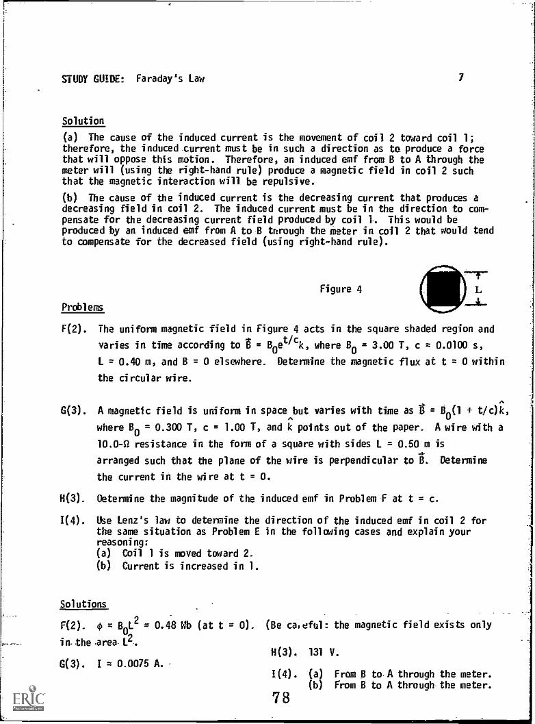
STUDY GUIDE: Faraday's Law 7
Solution
(a) The cause of the induced current is the movement of coil 2 toward coil 1;therefore, the induced current must be in such a direction as to produce a forcethat will oppose this motion. Therefore, an induced emf from B to A through themeter will (using the right-hand rule) produce a magnetic field in coil 2 suchthat the magnetic interaction will be repulsive.
(b) The cause of the induced current is the decreasing current that produces adecreasing field in coil 2. The induced current must be in the direction to com-pensate for the decreasing current field produced by coil 1. This would beproduced by an induced emf from A to B through the meter in coil 2 that would tendto compensate for the decreased field (using right-hand rule).
Figure 4
Problems
L
F(2). The uniform magnetic field in Figure 4 acts in the square shaded region and
varies in time according to t = Boet/c
k, where Bo = 3.00 T, c = 0.0100 s,
L = 0.40 m, and B = 0 elsewhere. Determine the magnetic flux at t = 0 within
the circular wire.
G(3). A magnetic field is uniform in space but varies with time as = B0(1 t/c)k,
where B0= 0.300 T, c = 1.00 1', and k points out of the paper. A wire with a
10,0-R resistance in the form of a square with sides L = 0.50 m is
arranged such that the plane of the wire is perpendicular to B. Determine
the current in the wire at t = O.
H(3). Oetermine the magnitude of the induced emf in Problem F at t = c.
1(4). Use Lenz's law to determine the direction of the induced emf in coil 2 forthe same situation as Problem E in the following cases and explain yourreasoning:
(a) Coil 1 is moved toward 2.
(b) Current is increased in I.
Solutions
F(2). 0 = BoL2= 0.48 Wb (at t = 0). (Be caieful: the magnetic field exists only
in-the .area.L2 .
G(3). I = 0.0075 A. ,
H(3). 131 V.
1(4). (a) From B to A through the meter.(b) From B to A through the meter.
78

STUDY GUIDE: Faraday's Law a
PRACTICE TEST
1. The magnetic field in a certain region of space is given by
g(t) = 0.300 sin(lOOt)k T.
A 50-turn loop of cross-sectional area 0.60 m2 lies in the xy plane.
(a) Write Faraday's law and define all terms with correct units.
(b) Calculate the flux through the coil at t = 0.
(c) Use Faraday's law to calculate the magnitude of the induced emf in the
coil at t = 0.
2. A current-carrying solenoid is moved toward a conducting loop as in Figure 5.Use Lenz's law to determine the direction of the induced current and explainyour reason.
Figure 5
olouatos atp tadaa ptnom 4eq4 ptalA apauBem e aanpoadptpom 4uaaana asImpotaaa4unoa y uopow slap asoddo o4 se uopaaalp e qans
u; aq 4snw Boot aq u; paaana aq aawaatil 64a aq paemo4 pawaAow ate s;4uaaana paanpu; op Ao asnea aqj 'asplaotaaa4unoa aq aim paaan3 paanpul aqj z
'A 006 = s/qM 006( s 000(1 00C0)(zw 09'0)(05) = 3 '0 = 4 4V '(400t S03 000000WN =
(410/(4000u1s(00C0)P] iN = (4P/OP)VN = (H)(4P/P)N = :P /4P = 3 (3)'0 = (09'0)(0)uls oorom = V9N = WAN = VP ON = 0 (q)
(sla4am aaenbs)eaae JOAO paua6a4u; (setsa4) .g PLa14 314au6ew aq = (saaqam)ff ON = 0
s; xnl3 aqi '(s41.0A)3 = pa paanpup aqi '4P/Op- = 3 s; met slAtpeaej (e) 't
79saamsuy 4sai aappead

FARADAY'S LAW
Mastery Test form A
Name
Date
pass recycle
1 2 3 4
Tutor
A plane circular wire loop in Figure 1-of radius = 0.050 m and resistance = 2.00 L.lies in the plane y = 0 in a .patially uniform magnetic field B = 0.100 cos(2xt/8)j.
1. Write Faraday's law and define all terms with correct units.
2. Calculate the magnetic flux through the loop at t = 1/6 s.
3. Use Faraday's law to determine the induced current in the loop.
4. Use Lenz's law to determine the direction of the induced current in the loopat t = 1/6 s and *xplain your reason.
Figure 1
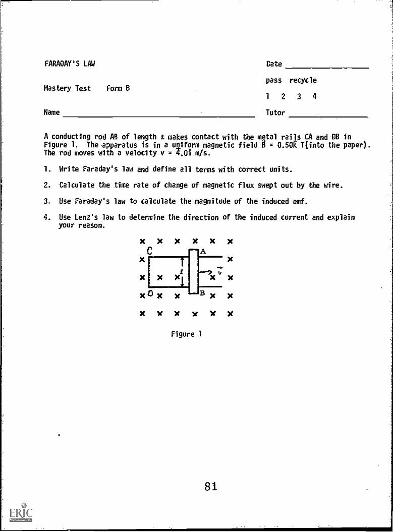
FARADAY'S LM
Mastery Test Form B
Name
Date
pass recycle
1 2 3 4
Tutor
A conducting rod AB of length makes contact with the mgtal rails CA and DB inFigure 1. The apparatus is in a uniform magnetic field 0 = 0.50E Tinto_ the paper).The rod moves with a velocity v = 4.0i m/s.
1. Write Faraday's law and define all terms with correct units.
2. Calculate the time rate of change of magnetic flux swept out by the wire.
3. Use Faraday's law to calculate the magnitude of the induced emf.
4. Use Lenz's law to determine the direction of the induced current and explainyour reason.
X
X
)t )t X X )t
A
X le X x y xFigure 1
81

FARADAY'S LAW
Master Test Form C
Name
Date
pass recycle-
1 2 3 4
Tutor
A circular wire coil of radius b in the plane of this Page and resistance R is in
a uniform magnetic field that varies with time as B = Boe-titO, where B and t40
are constant and the magnetic field makes an angle of v/3 with the plane of the
coil.
1. Write Faraday's law and define all terms with correct units.
2. Calculate the magnetic flux through the circular wire at t = to.
3. Use Faraday's law to determine the magnitude of the induced current in -the coil.
4. Use Lenz's law to determine the dirEction of the induced current and explainyour reason.
82
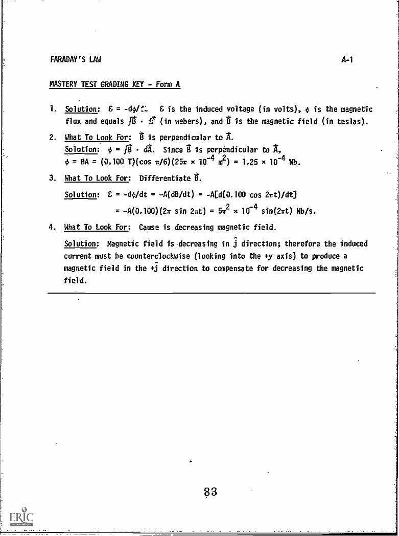
FARADAY'S LAW
MASTERY TEST GRADING KEY - Form A
A-1
1. Solution: & = & is the induced voltage (in volts), is the magnetic
flux and equals g It (in webers), and is the magnetic field (in teslas).
2. What To Look For: is perpendicular to AL
Solution: 4, = g dt Since rf is perpendicular to 14
= BA = (0,100 T)(cos w/6)(251 x 10-4 mF) = 1.25 x 10⁻⁴ Wes.
3. What To Look For: Differentiate t
Solution: & = -do/dt = -A(dB/dt) = -AEd(0.100 cos 2wt)/dt]
= 4(0.100)(2w sin 270 = 51r2 x 104 sin(2wt) Wb/s.
4. What To Look For: Cause is decreasing magnetic field.
Solution: Magnetic field is decreasing in j direction; therefore the induced
current must be countercTockwise (looking into the 41, axis) to produce a
magnetic field in the +j direction to compensate for decreasing the magnetic
field.
83
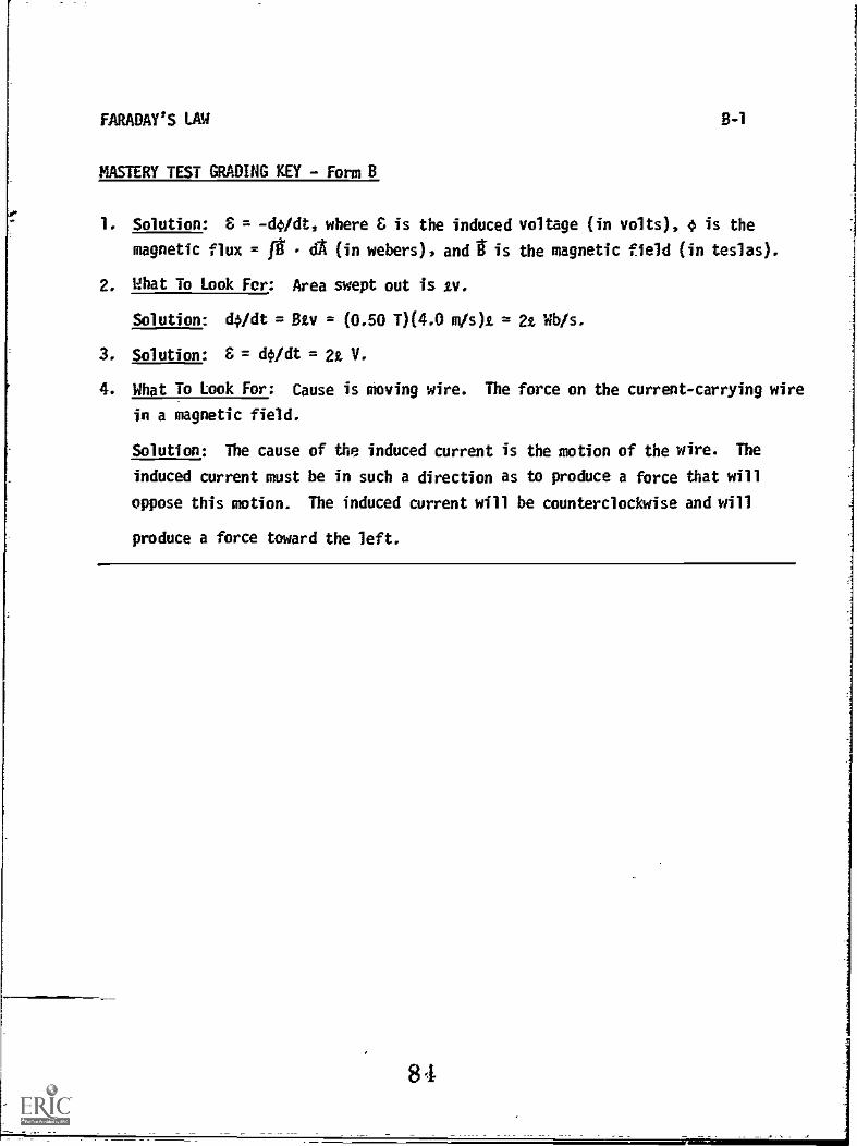
FARADAY'S LAW
MASTERY TEST GRADING KEY - Form B
8-1
1. Solution: 8 = -4/dt, where £ is the induced voltage (in volts), 4 is the
magnetic flux = 0 dA (in webers), and t is the magnetic field (in teslas).
2. What To Look For: Area swept out is zv.
Solution: doidt = Sty = (0.50 T)(4.0 m /s)t = 2t rib /s.
3. Solution: 8 = dOidt = 2t V.
4. What To Look For: Cause is moving wire. The force on the current-carrying wire
in a magnetic field.
Solution: The cause of the induced current is the motion of the wire. The
induced current must be in such a direction as to produce a force that will
oppose this motion. The induced current will be counterclockwise and will
produce a force toward the left.
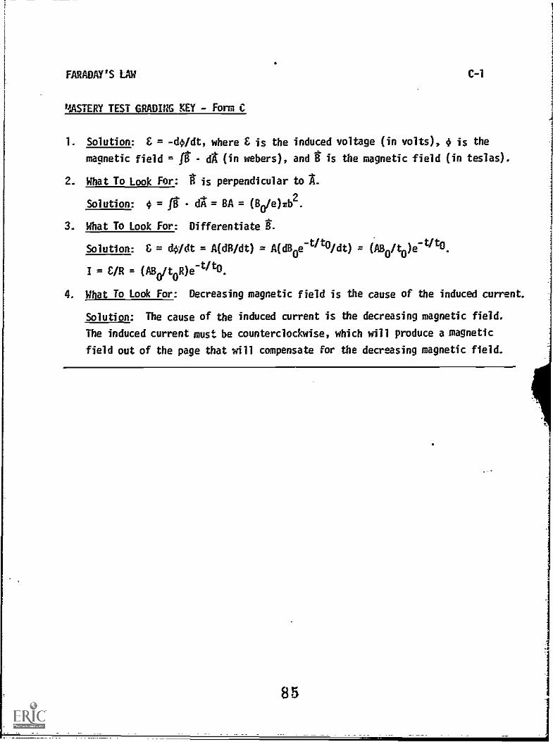
FARADAY'S LAW C-1
MASTERY TEST GRADIUG KEY - Form C
1. Solution: E = -do/dt, where E is the induced voltage (in volts), 4 is the
magnetic field = ft - a (in webers), and it is the magnetic field (in teslas).
2. What To Look For: t is perpendicular to A.
Solution: 4 = ft dA:= BA = (80/e)Tb2.
3. What To Look For: Differentiate t.
Solution: & = do/dt = A(dB/dt) = A(dBoe-t/tO/dt) = (A8o/t0)e-t/t0.
I = = (1180/t0R)e-t/10.
4. What To Look For: Decreasing magnetic field is the cause of the induced current.
Solution: The cause of the induced current is the decreasing magnetic field.
The induced current must be counterclockwise, which will produce a magnetic
field out of the page that will compensate for the decreasing magnetic field.
85