Download - AFPA / VFG 2 - Danfoss
Instructions
6 000 005 876 DEBC 04 / 2003 VICAJ16Z
Type AFPA / VFG 2 (21) DN 15-250
1
Differential Pressure Relief ControllerAFPA / VFG 2 (21)ENGLISH
FRANCAIS
DEUTSCH
POLSKI
Page 2www.danfoss.de
Page 2www.danfoss.fr
DifferenzdrucküberströmreglerAFPA / VFG 2 (21)
Seite 2www.danfoss.de
Strona 2www.danfoss.pl
Régulateur de pression différentielle, ouvrantAFPA / VFG 2 (21)
�������� �� ������ ������������������������
����������������
www.danfoss.com�� �������������������������������������������
2
Type AFPA / VFG 2 (21)
�������
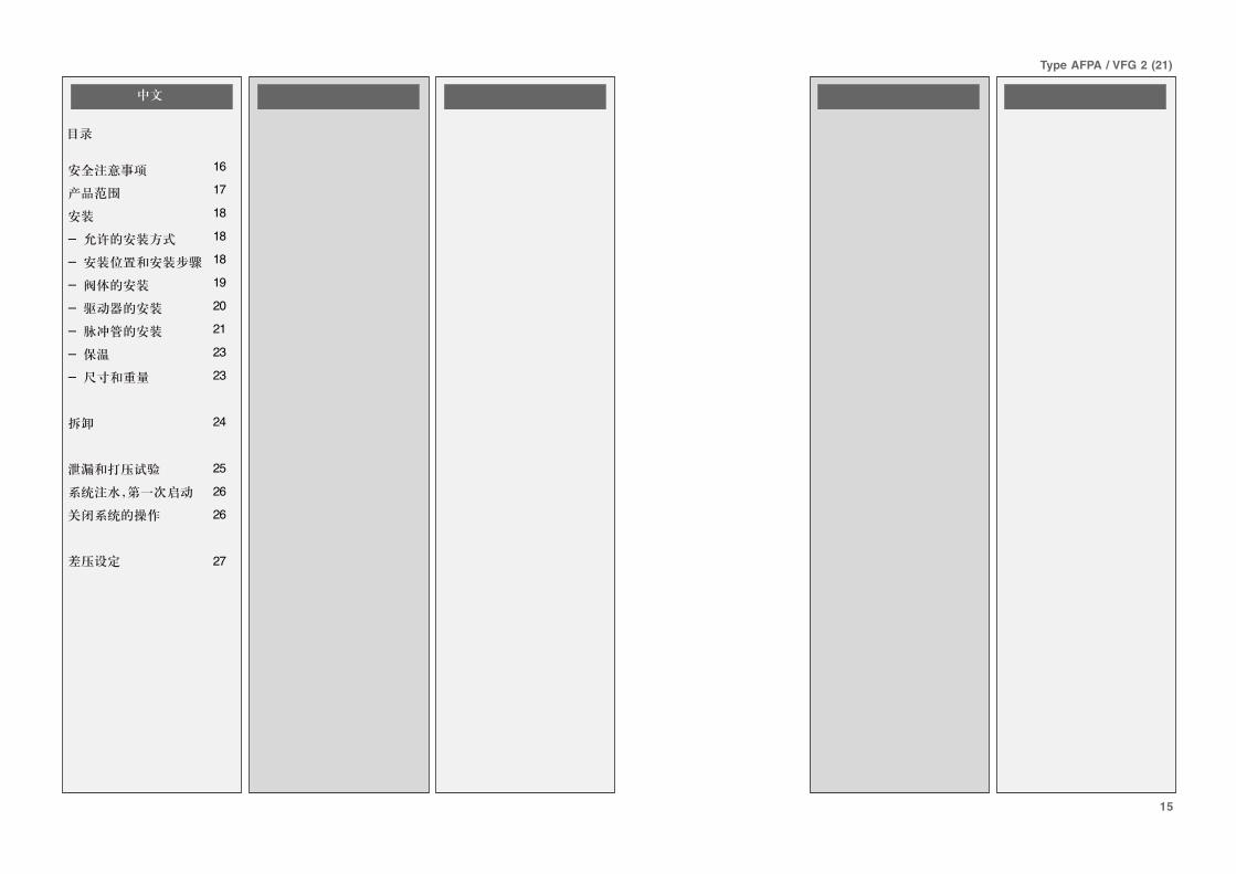
Contents
Safety Notes 3
Scope of Delivery 4
Mounting 5
- Admissible Installa-tion Position 5
- Installation Locationand Installationscheme 5
- Valve Installation 6
- Valve ActuatorInstallation 7
- Impulse TubeInstallation 8
- Insulation 10
- Dimensions,Weights 10
Dismounting 11
Leak and PressureTests 12
Filling the System,First Start-up 13
Putting out ofOperation 13
Differential PressureSetting 14
DEUTSCH
Inhalt
Sicherheitshinweise 3
Lieferumfang 4
Montage 5
- ZulässigeEinbaulagen 5
- Einbauort,Einbauschema 5
- Einbau Ventil 6
- Montage VentilAntrieb 7
- MontageSteuerleitungen 8
- Isolierung 10
- Abmessungen,Gewichte 10
Demontage 11
Dichtheits-,Druckprüfung 12
Füllung der Anlage,Inbetriebnahme 13
Außerbetriebnahme 13
EinstellungDifferenzdruck 14
FRANCAIS
Sommaire
Consignes de sécurité 3
Contenu de la livraison 4
Montage 5
- Orientations demontage autorisées 5
- Lieu de montage,schéma de montage 5
- Montage vanne 6
- Montage vanne,moteur 7
- Montage conduitesde commande 8
- Isolation 10
- Dimensions / poids 10
Démontage 11
Contrôle d’étanchéitéet de pression 12
Remplissage del’installation, miseen service 13
Mise hors service 13
Réglage de la pressiondifférentielle 14
POLSKI
��� �
!�"����"������ #
$�%�� &������ '
(� ��� )
* +����"�"�� ���"��,�-� ���� )
* (��,��� � ��.�-��-� ���� )
* (� ���"���� /
* (� ��� ��0&� 1
* ��&23�"� ���"���&���-��������. 4
* 5"����,� �6
* 7�-����7��� �6
+�-� ��� ��
��!� ��� �� ���� ��"�"�� ���� ��
8���2 �� �� �%2�&�9�����"� ���.�-�� �� �#
$��"�-� ���%2�&� �#
8������ ������� �,�� ������ ��� �'
�������
����� �
������������!��"���#��������� $
%�&���"����� '
(����) *
+ ,�� ���&-�����)������� ����������&����)� *
+ �#&�.������� ���������!�&� ������"�� *
+�(����)�"������ /
+�(����)��� ��� 0.���1��&���� 2
+ (����)��&� �3��-!�� ��" 4
+ 5�����#������ �6
+ 7�������-����������������3�-���#&��- �6
,�&����) ��
8��-������ �����9����3�����&���9����3 �
:���������� �����&-;����-<� #�� �" �$
=�"�09����� �����&- �$
>�����<"�� ���������������� �'
3
Type AFPA / VFG 2 (21)
ENGLISH
�����������
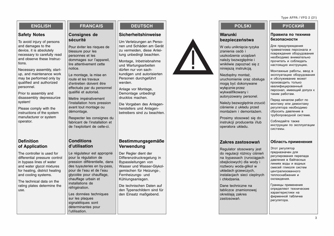
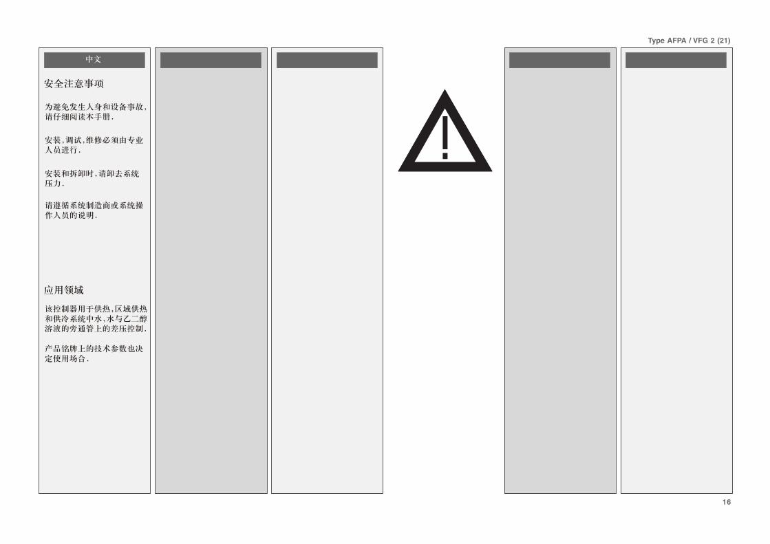
To avoid injury of personsand damages to thedevice, it is absolutelynecessary to carefully readand observe these Instruc-tions.
Necessary assembly, start-up, and maintenance workmay be performed only byqualified and authorizedpersonnel.
Prior to assembly anddisassembly depressurizesystem!
Please comply with theinstructions of the systemmanufacturer or systemoperator.
Definitionof Application
The controller is used fordifferential pressure controlin bypass lines of waterand water glycol mixturesfor heating, district heatingand cooling systems.
The technical data on therating plates determine theuse.
DEUTSCH
Sicherheitshinweise
Um Verletzungen an Perso-nen und Schäden am Gerätzu vermeiden, diese Anlei-tung unbedingt beachten.
Montage, Inbetriebnahmeund Wartungsarbeitendürfen nur von sach-kundigen und autorisiertenPersonen durchgeführtwerden.
Anlage vor Montage,Demontage unbedingtdrucklos machen.
Die Vorgaben des Anlagen-herstellers und Anlagen-betreibers sind zu beachten.
BestimmungsgemäßeVerwendung
Der Regler dient derDifferenzdruckregelung inBypassleitungen vonWasser und Wasser-Glykol-gemischen für Heizungs-,Fernheizungs- undKühlungsanlagen.
Die technischen Daten aufden Typenschildern sind fürden Einsatz maßgebend.
FRANCAIS
������������
�������
Pour éviter les risques deblessure pour lespersonnes et lesdommages sur l’appareil,lire attentivement cettenotice.
Le montage, la mise enroute et les travauxd’entretien doivent êtreeffectués par du personnelqualifié et autorisé.
Mettre impérativementl’installation hors pressionavant tout montage oudémontage.
Respecter les consignes dufabricant de l’installation etde l’exploitant de celle-ci.
Conditionsd’utilisation
Le régulateur est appropriépour la régulation depression différentielle, dansdes tuyauteries en by-pass,pour de l’eau et de l’eauglycolée pour chauffage,chauffage urbain etinstallations deréfrigération.
Les données techniquessur les plaquessignalétiques sontdéterminantes pourl’utilisation.
POLSKI
��� �
�������������
7����� �% �0����"�%�"� �� �����! ���"%�&"� ���"3&"�� �����!�"�"��0& ���� �%�����"���" �:��0" � ��,�"3 � ���%�,39
8��"!0& �-� �������.�-�� �� ��" �!�2���-��3!�:&�%� ��� ���23�" ���"�"��%����;�%��� �������"��� ����� ��9
8�����!�"�"��0& ��""���:��� �� ��"�%2�&��"�&-� ����- � &�-� ����-9
����-� �������: ��0 &�� ���%�,� ��&��� �� ����!������� �%2�&�9
�����������
�������� ������� � ,���&� ������,� �� ������ ��� � !�������. �����3���.�!�,�������. &����&���"������&�*���%����%2�&��.�"���"��.�� ������,��. ����� ����� ��.� �.2�&"� ��9
+� ����. ��" � ���!���"�� " �-�� ���,�%����,3 "�%��"���������9
�������
������������ �������� ����
,��� ���� ���)���������&���#&�� ���������� ������)������ ���� �����������!���&�� ���&����3�����9����3� �� ����0���3������. 0� ����� "��0?
(����)�-�� �����-;� ����� �1"��� �����0� ���� ��������� ���� )�������&�)������#�����3� ���3"�"����@���������-<��������;��&�0.�<���� �"�"��"�&� ������&?
�������9���&���������&����) � ���� ��&����) ��� ������� ����!���&��������3� ��������� ��� ����������<� �����&�?
����0��<��� ��")������ "���� ��� 1"��� �����������&-?
����������� ��
A���� ��� �����������#��9��������� ���������� ����������������� �� ��<����-!�����!� ���-��� ����-!�&���<� ���"���� �����&��������#�����������������)����� ��!��)�����?
7�����-����&��������������0�� ��!��9��"��!���"�������"�� ��@��&����<� �����9"���� ������?
4
Type AFPA / VFG 2 (21)
ENGLISH
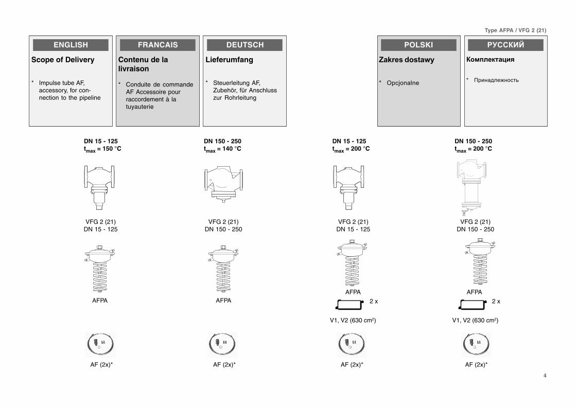
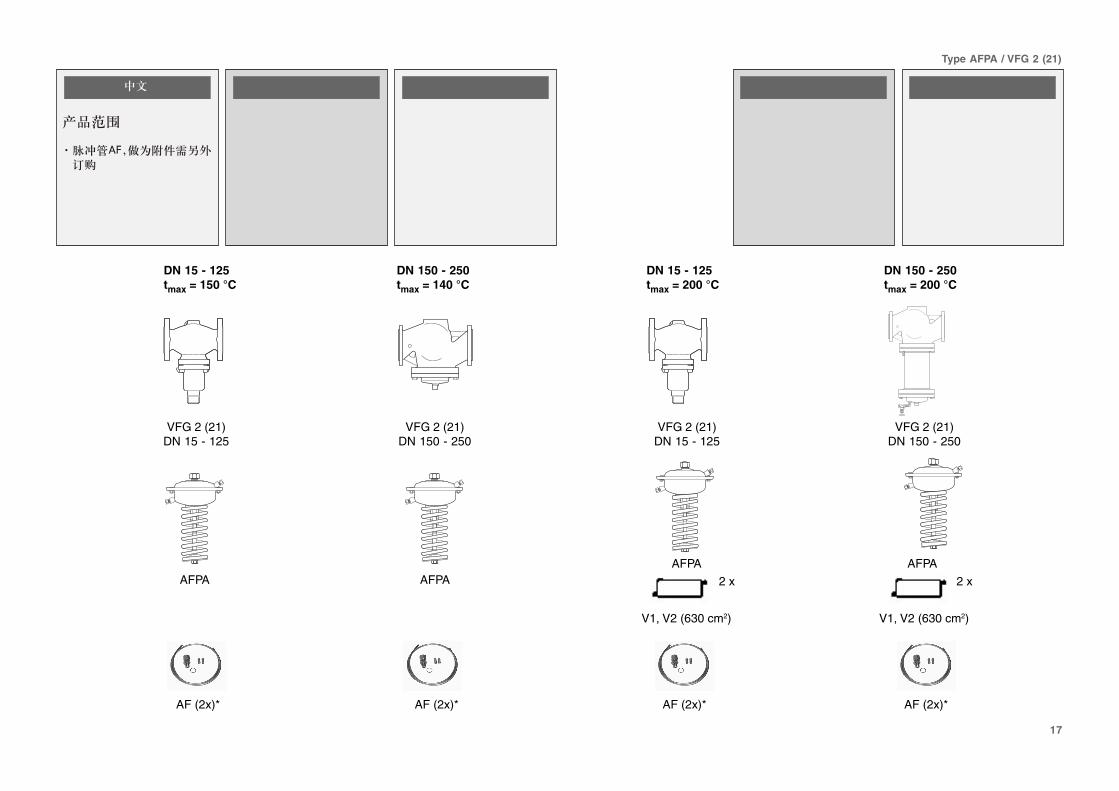
Scope of Delivery
* Impulse tube AF,accessory, for con-nection to the pipeline
DEUTSCH
Lieferumfang
* Steuerleitung AF,Zubehör, für Anschlusszur Rohrleitung
FRANCAIS
Contenu de lalivraison
* Conduite de commandeAF Accessoire pourraccordement à latuyauterie
POLSKI
���������
< =��,� �� �
�������
�����������
B �������)����3
DN 150 - 250tmax = 200 °C
AF (2x)*
VFG 2 (21)DN 150 - 250
V1, V2 (630 cm2)
AFPA
DN 15 - 125tmax = 200 °C
VFG 2 (21)DN 15 - 125
AF (2x)*
AFPA
DN 150 - 250tmax = 140 °C
VFG 2 (21)DN 150 - 250
AF (2x)*
VFG 2 (21)DN 15 - 125
AFPA
DN 15 - 125tmax = 150 °C
AF (2x)*
AFPA
2 x
V1, V2 (630 cm2)
2 x
5
Type AFPA / VFG 2 (21)
ENGLISH
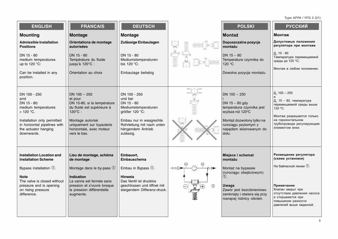
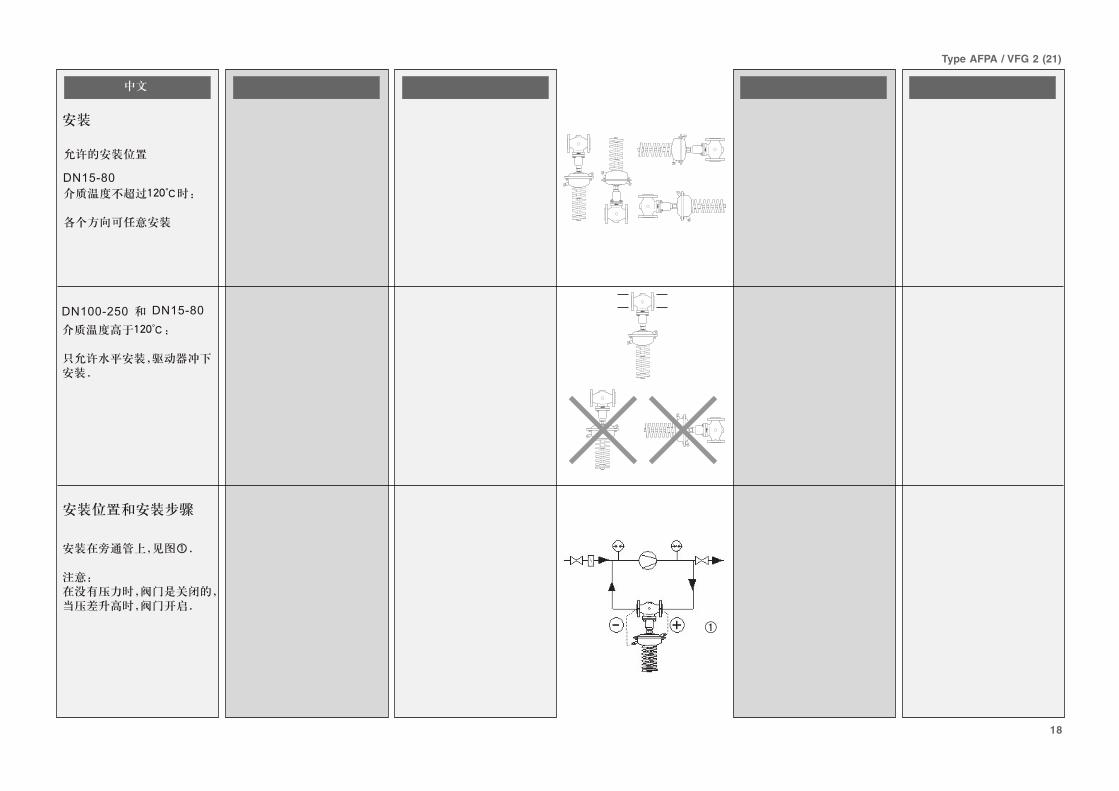
Mounting
!�"�����#������##����
$��������
DN 15 - 80medium temperaturesup to 120 °C:
Can be installed in anyposition.
DN 100 - 250andDN 15 - 80:medium temperatures> 120 °C.
Installation only permittedin horizontal pipelines withthe actuator hangingdownwards.
Installation Location andInstallation Scheme
Bypass installation ➀.
NoteThe valve is closed withoutpressure and is openingon rising pressuredifference.
FRANCAIS
Montage
Orientations de montageautorisées
DN 15 - 80Température du fluidejusqu’à 120°C :
Orientation au choix
DN 100 – 250et pourDN 15-80, si la températuredu fluide est supérieure à120°C :
Montage autoriséuniquement sur tuyauteriehorizontale, avec moteurvers le bas.
Lieu de montage, schémade montage
Montage dans le by-pass ➀
IndicationLa vanne est fermée sanspression et s’ouvre lorsquela pression différentielleaugmente.
DEUTSCH
Montage
Zulässige Einbaulagen
DN 15 - 80Mediumstemperaturenbis 120 °C:
Einbaulage beliebig
DN 100 - 250und beiDN 15 - 80Mediumstemperaturengrößer 120 °C:
Einbau nur in waagrechteRohrleitung mit nach untenhängendem Antriebzulässig.
Einbauort,Einbauschema
Einbau in Bypass ➀.
HinweisDas Ventil ist drucklosgeschlossen und öffnet mitsteigendem Differenz-druck.
POLSKI
%���&
'�������#��������(�
"���&�
+8�)>46?�-�������"� �%�&���6�@
+���� ���"��,�-� ����
+8�66>�)6�+8�)>46�&���-�������"� �%� ,�������"� ����6�@
(� ���&�"���� ����%� �����3����"��-�-" ��0&�- �%����� �-&�&�2�9
%��(��������)�"�
"���&�
(� ��� �!������������3�� �!�,������- ➀9
*��
$��� ,��� !�"��� �� ����"�-% �0�����������0�"��� 3��, �� ��� ��� ���9
�������
�� ���
��!����"� ����� ��#!������ ����� ���
,C��*�+�46
5�&����� ��� ����&�.��&�<����-�����6�=�D
(����)����0��&�����)����?
,C��66�E�*6
�,C��*�E�46;� ��&����� ��
����&�.��&�<� ����-��-F��6�=�D
(����)���#��F������ ���3"���� ����#�����3��&�� ���������� ��� ��� 0.�&1��&����&� ���#
����$ �� #!�����%����� !��� ����&
>����<�����<�������➀?
���'� �%������ #�"�-�� ������ ������� ��������� �������� ��"�-������� ������-F����� ��#������������<��-F�� #������<?
➀
6
Type AFPA / VFG 2 (21)
FRANCAIS
Montage vanne
1. Monter le filtre ➀ devantle régulateur
2. Rincer l’installation avantle montage
3. Respecter le sensd’écoulement ➁ indiquésur la vanne
Les brides ➂ dans latuyauterie doivent êtreparallèles, les surfacesd’étanchéité propres etsans dommages.
4. Monter la vanne
5. Serrer les vis en 3étapes en croix, jusqu’aucouple de rotation max.
DEUTSCH
Einbau Ventil
1. Schmutzfänger ➀ vordem Regler einbauen.
2. Anlage vor dem Einbaudes Ventils spülen.
3. Durchflussrichtung ➁auf dem Ventilgehäusebeachten.
Flansche ➂ in der Rohr-leitung müssen parallel,Dichtflächen sauber undohne Beschädigung sein.
4. Ventil einbauen.
5. Schrauben über Kreuzin 3 Stufen bis zummax. Drehmomentanziehen.
POLSKI
%���&�����
�9 $�-� ����:;���➀�"�& ��������-9
�9�"�&"�-� ���� ��-"�����"��2�%�:� ������,09
#9 $����:����0 ���%�A �% %��� %��"��2���➁ �%������"����9
B�2 ��"�➂ �����3��-��"3!�:�"�,�- ���� ����2�� � �����"�. ����&��"�"��%��"�����!�"��"%�&"��9
'9 $�-� ����:"���9
)9 +�%0��: �"�������2� �%0�%��#%�%��.&����3� �0���-�%��-�� ���-�-� ��9
�������
�� ��������� �
�? �������� ������& ��������3� ���9��-<@��3���➀?
? ����� ������"�<� "���������&-�3� �����& ?
$? ������3� ���������������"���������"��➁���"��� ��� "������?
G����-�➂� ��� �� ������������)�-� �-�3� ���������-��������3��;� �� �������&-������!������ ���)�-� �-�39���-&���� ��#� �����)����<?
'? C��������3� "�����?
*? %���������#��� #���� �3����-��� ���� 1������������)����&�"��&��3����� "� ��.���&�&����?
ENGLISH
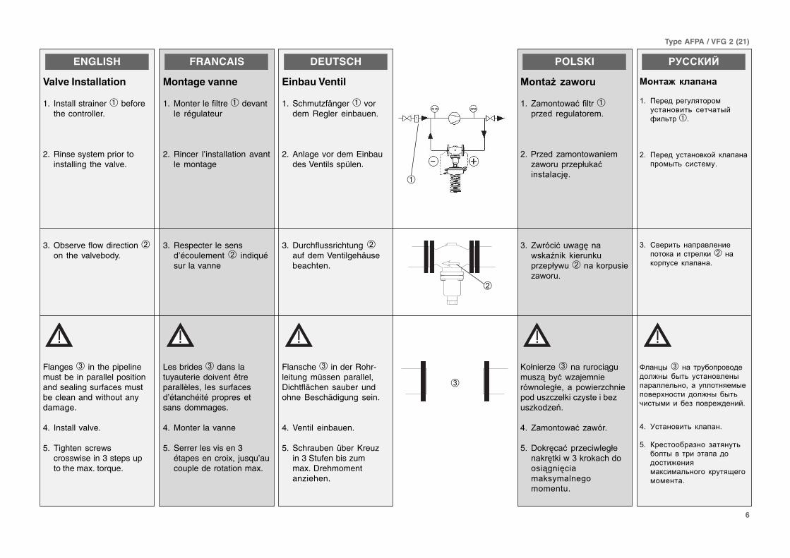
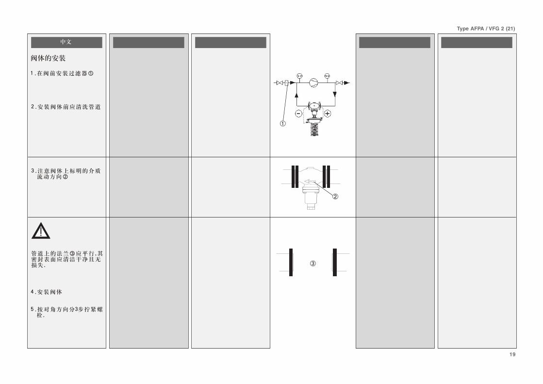
Valve Installation
1. Install strainer ➀ beforethe controller.
2. Rinse system prior toinstalling the valve.
3. Observe flow direction ➁on the valvebody.
Flanges ➂ in the pipelinemust be in parallel positionand sealing surfaces mustbe clean and without anydamage.
4. Install valve.
5. Tighten screwscrosswise in 3 steps upto the max. torque.
➂
➁
➀
7
Type AFPA / VFG 2 (21)
FRANCAIS
Montage vanne,moteur
Vannes DN 150 - 250
Pour les vannes DN 150 -250 la tige du moteur doitêtre vissée dans la tige dela vanne.
Lire attentivement la noticede montage ➁ jointe auxvannes DN 150 - 250.
Vannes DN 15 - 125
1. Positionner le moteursur la vanne
2. Aligner le moteur avecle raccordement deconduite de commande➀
3. Serrer l’écrou prisonnier➁, facteur de serrage100 Nm
$+��,�
%���&���-��
����'��./0�1�2/0
7"�����.+8�)6*�)6�"���� ��0&�-���"����:�%0�� ���"����"����9
C"�"���2�" ���A:-�� ��5 ���%�,�(� ����"�����+8�)6*�)69
����'��./�1�.2/
�9 D-�����: ��0& �"���"�9
�9 D�����: ��0&��-�0��,3����"��,��"�23�"��"���&��-���������➀
#9 +�%0��: �%0�%023�"3�3E9(�-� �F�668-
�������
�� ���#!��!($#�)�� ��
%�����-�,C��*6�+�*6
,���"��������,C��*6�+�*6
F��"� ��� ��� 0.���1��&����� � ���)����-�3#����9��� ��F��"� "������?
=������&����� �����������&����� ��� ����� "��0���&����) ;� ��������& 0� "�������"��������,
C��*6� +
*6
����� "� ��*+�,�*-+
�? �&�����3��� ��� 0.�<� 1��&������"������?
? ����� �3� 1��&���� ������ �&���� ����)����F� �����➀�����&� �3���<� �� �"�
$? :���� �3����������3� 0� ��<" � � H"� ��.�&�&�&����&� �66>&
DEUTSCH
MontageVentil und Antrieb
Ventile DN 150 - 250
Bei den VentilenDN 150 - 250 muss dieAntriebstange in die Ventil-stange eingeschraubtwerden.
Den Ventilen DN 150 - 250beigefügte Montage-anleitung ➁ beachten.
Ventile DN 15 - 125
1. Antrieb am Ventilansetzen.
2. Antrieb wegen demSteuerleitungsan-schluss ➀ ausrichten.
3. Überwurfmutter ➁anziehen Anzugs-moment 100 Nm
➀➁
46 mm
100 Nm
DN 150 - 250
ENGLISH
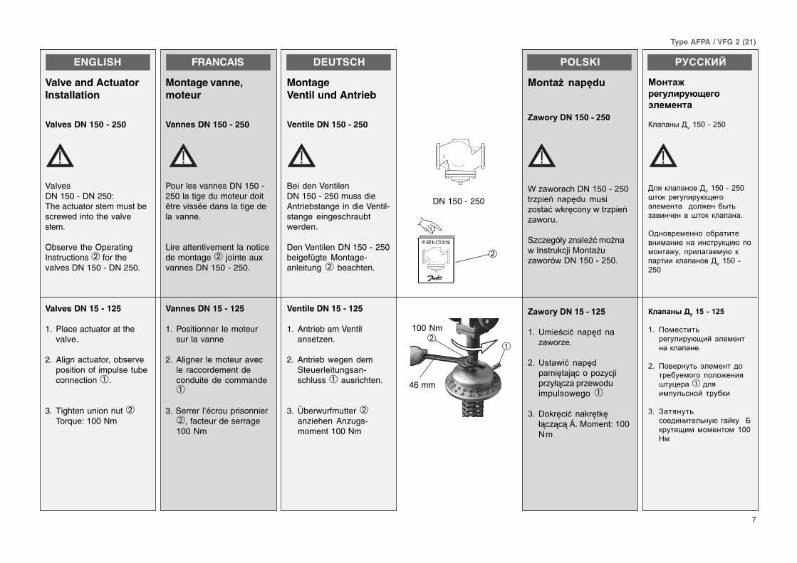
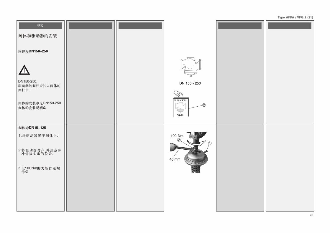
Valve and ActuatorInstallation
Valves DN 150 - 250
ValvesDN 150 - DN 250:The actuator stem must bescrewed into the valvestem.
Observe the OperatingInstructions ➁ for thevalves DN 150 - DN 250.
Valves DN 15 - 125
1. Place actuator at thevalve.
2. Align actuator, observeposition of impulse tubeconnection ➀.
3. Tighten union nut ➁Torque: 100 Nm
➁
8
Type AFPA / VFG 2 (21)
FRANCAIS
Montage conduites decommande
Avec montage de pots decondensation ➀, respecterla notice de montage jointeà ces pièces.
Quelles conduites decommande choisir ?
Utiliser le kit de conduite decommande AF (2x) ➁
Référence de commande :003G1391
Ou utiliser les conduitessuivantes :
Tuyauterie
Acier inox ø 10x0,8DIN 17458,DIN 2391
Acier ø 10x1DIN 2391
Cuivre ø 10x1DIN 1754
Les conduites decommande ➂ peuventêtre raccordéesdirectement à la vanne ➃ou
à la tuyauterie ➄
DEUTSCH
Montage Steuerleitungen
Hinweis
Bei Einbau von Vorlage-gefäßen ➀, bitte denVorlagegefäßen bei-gefügteMontageanleitungbeachten.
Welche Steuerleitungenverwenden?
SteuerleitungssetAF (2x) ➁
Bestellnummer: 003G1391oder folgende Röhreverwenden:
Rohr
Edelstahl Ø 10x0,8DIN 17458,DIN 2391
Stahl Ø 10x1DIN 2391
Kupfer Ø 10x1DIN 1754
Die Steuerleitungen ➂können direkt amVentil ➃
oder
an der Rohrleitung ➄angebracht werden .
POLSKI
$��34�������������5�
�"��#�����)
*��
G���� � ������� � �3 ��"� �� %� &� ����, ���"�"���2�" ���A:-�� ��5 ���%�,�(� ���� ��"� ��9
G�%�� �"���&� �-������� �����"��������:H
(�� �"��������:"�������%�-��������.����I ➁F
8 "�-���� ����F66#��#J�
��!�%�� ���0��,3���.���-����.F
��%�
Stal nierdzewna Ø 10x0,8DIN 17458,DIN 2391
C��� �6I�+58�#J�
(��&A �6I�+58�1)'
$��������"��#�����➂"��4�����6����34�����
�����7��������������➃
#��
�������4���➄
�������
�� �������!��� "��!���
���'� �.� ��� ������"� ���������3�-!� 1��&��������F� �����➀� �����0��<������� "���� ��� �!�&����) ?
%�" 0� �&� �3�� 0� �� �" ���� ��� �-����3I
(�)��� �����3#����3"�&���"�� �&� �3��-!� �� ��"����J���➁D
%����-<���&��D� 66$��$K�
L���������3# 0������ ����&� �3��-�� �� �"�;� ��� �!��#&��-� ���� ��� �-�����3� �������������� �� ����������<�������<D
(�������� �� �"��#&��
>��)���0.��� ����3 ø�6!6;4MNO��2'*4MNO�$K�
����3 ø�6!�MNO�$K�
(��3 ø�6!�MNO��2*'
���!��� "��!����➂��#!���"��������(' " ������� �� ������ !�➃� ������!�������!�➄/
ENGLISCH
➀
G 1/4
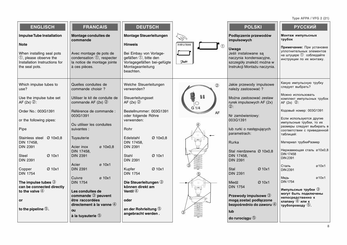
Impulse Tube Installation
Note
When installing seal pots➀, please observe theInstallation Instructions forthe seal pots.
Which impulse tubes touse?
Use the impulse tube setAF (2x) ➁:
Order No.: 003G1391
or the following pipes:
Pipe
Stainless steel Ø 10x0,8DIN 17458,DIN 2391
Steel Ø 10x1DIN 2391
Copper Ø 10x1DIN 1754
The impulse tubes ➂can be connected directlyto the valve ➃
or
to the pipeline ➄.
AF
➁
➂
➃
➄
➂
9
Type AFPA / VFG 2 (21)
ENGLISH
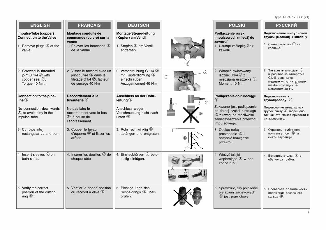
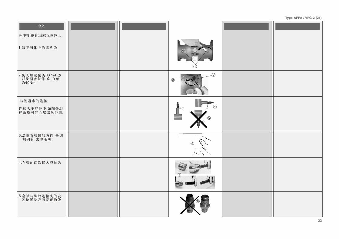
Impulse Tube (copper)Connection to the Valve
1. Remove plugs ➀ at thevalve.
2. Screwed in threadedjoint G 1/4 ➁ withcopper seal ➂,Torque 40 Nm.
Connection to the pipe-line ➃
No connection downwards⑤, to avoid dirty in theimpulse tube.
3. Cut pipe intorectangular ➅ and burr.
4. Inserrt sleeves ➆ onboth sides.
5. Verify the correctposition of the cuttingring ➇.
FRANCAIS
Montage conduite decommande (cuivre) sur lavanne1. Enlever les bouchons ➀
de la vanne
2. Visser le raccord avec unjoint cuivre ➂ dans lefiletage G1/4 ➁, facteurde serrage 40 Nm
Raccordement à latuyauterie ➃
Ne pas faire leraccordement vers le bas⑤, à cause del’encrassement.
3. Couper le tuyaud’équerre ➅ et lisser lesarêtes
4. Insérer les douilles ➆ dechaque côté
5. Vérifier la bonne positiondu raccord à olive ➇
DEUTSCH
Montage Steuer-leitung(Kupfer) am Ventil
1. Stopfen ➀ am Ventilentfernen.
2. Verschraubung G 1/4 ➁mit Kupferdichtung ➂einschrauben,Anzugsmoment 40 Nm.
Anschluss an der Rohr-leitung ➃
Anschluss wegenVerschmutzung nicht nachunten ➄.
3. Rohr rechtwinklig ➅ablängen und entgraten.
4. Einsteckhülsen ➆ beid-seitig einfügen.
5. Richtige Lage desSchneidrings ➇ über-prüfen.
$+��,�
$��34���������
�"��#�����)�8"���9:���
����;
�9 D�� 3:"�����%0➀""����9
�9 7%0��:��� ���� �23�" �%���'➁"-��&"�� 3��"�"��%3➂9(�-� �'68-
$��34��������������4��
➃
$�%�"� � ,��� ��&23�"� ��&�&�� �, �"0��� ����3��➄"����� �-�������:"� ���"��"�"� ���"���&��-���������9
#9 =!��3:�%0�������&��➅ ���"����:%��0&"���"�%�,�9
'9 72���:����,%�������,3��➆��!�%�����%�9
)9 C���&"�:��"���2��� ��������� � "����%����.➇ ,��� ����&2���9
�������
�����(' �� ���!��� �0�!���� %�� �0&� �� ����� !
�? ����3�#��� F"��➀���"������?
? :����� �3�F� ���-�➁�� ��#3���-�� ������������'P;� �����3# �&���-�� ���������3�-�F�<�-�"� ��.�&�➂&�&����&�'6�>&?
�����(' �� ��!�������!� �➃
��"�09����� �&� �3��-!�� ��"� ���# �➄� #����.���;��"� "�"� 1���&�)��� ��������� "�!� #�������0?
$? =���#��3� �� �" � ������&-&� ���&��➅�������3� #� ����-?
'? Q������3� �� �"��➆� ����� "������� �"�?
*? �����3�� ������3����3����)���� ��#��#����"��3���➇?
➁
➀
➂
➄
➃
➅
➆
➇
10
Type AFPA / VFG 2 (21)
ENGLISH
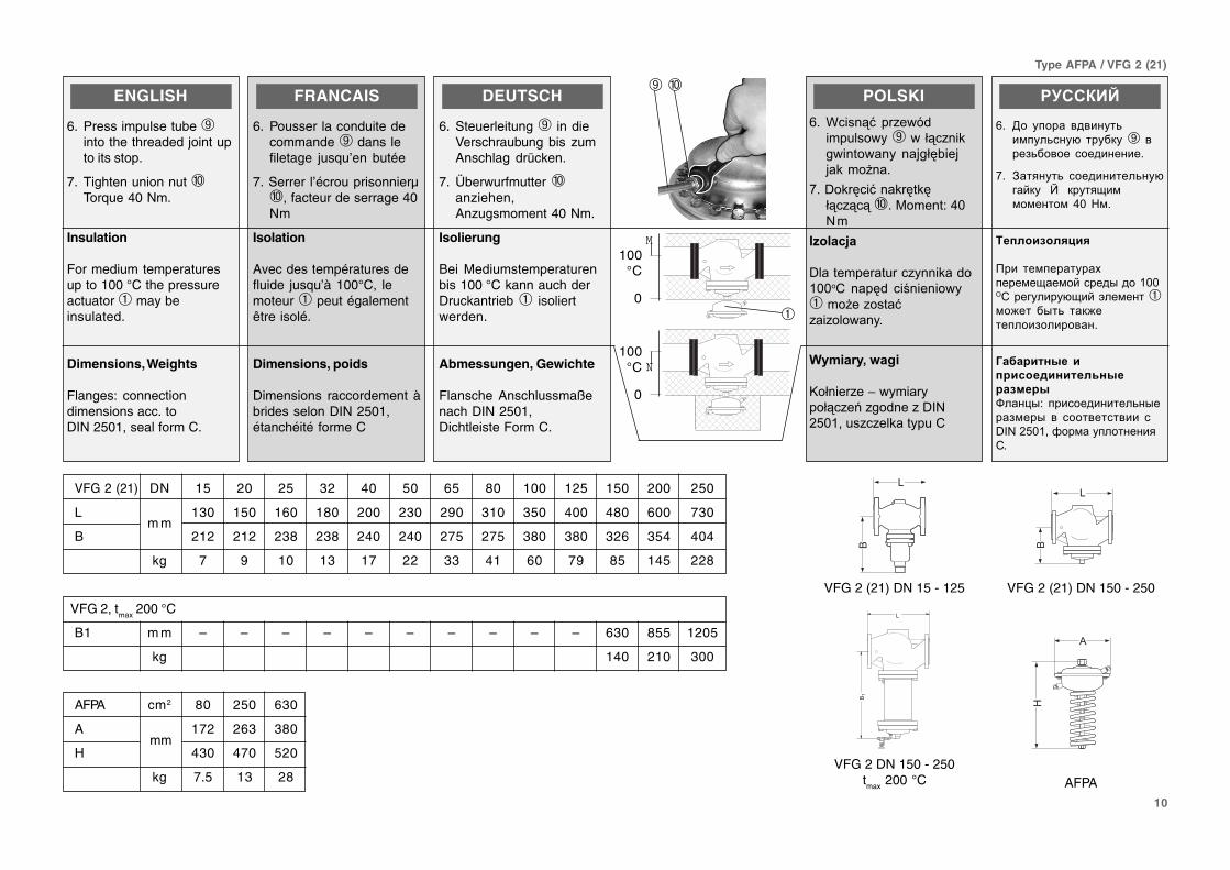
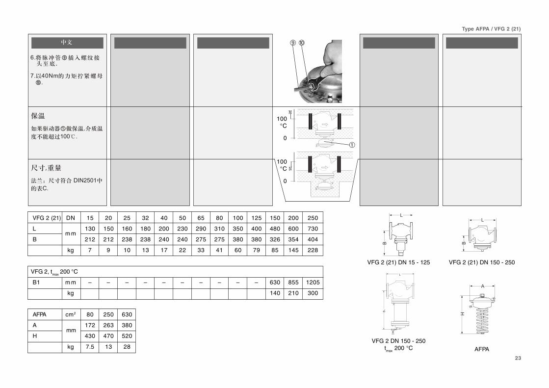
6. Press impulse tube ➈into the threaded joint upto its stop.
7. Tighten union nut ➉Torque 40 Nm.
Insulation
For medium temperaturesup to 100 °C the pressureactuator ➀ may beinsulated.
Dimensions, Weights
Flanges: connectiondimensions acc. toDIN 2501, seal form C.
FRANCAIS
6. Pousser la conduite decommande ➈ dans lefiletage jusqu’en butée
7. Serrer l’écrou prisonnierµ➉, facteur de serrage 40Nm
Isolation
Avec des températures defluide jusqu’à 100°C, lemoteur ➀ peut égalementêtre isolé.
Dimensions, poids
Dimensions raccordement àbrides selon DIN 2501,étanchéité forme C
DEUTSCH
6. Steuerleitung ➈ in dieVerschraubung bis zumAnschlag drücken.
7. Überwurfmutter ➉anziehen,Anzugsmoment 40 Nm.
Isolierung
Bei Mediumstemperaturenbis 100 °C kann auch derDruckantrieb ➀ isoliertwerden.
Abmessungen, Gewichte
Flansche Anschlussmaßenach DIN 2501,Dichtleiste Form C.
POLSKI
/9 7��� 3: �"���&�-�������➈�23�" �%��� ���� � �,�20!��,,�%-�� �9
19+�%0��: �%0�%023�"3�3➉9(�-� �F'68-
���#�(
+����-������"� �%�&��66�@ ��0& ��� �� ����➀-���"����:"��"����� �9
��"��<����
B�2 ��"�>��-�����23�"��"��& �"+58�)6����"�"��%�����@
�������
/? ,�� ����� ����� �3�&� �3�� 0� �� �" �➈� ���#3������ ����������?
2? :���� �3� ����������3� 0��<" � �R� �"� ��.�&&�&����&�'6�>&?
1�����������
��� ��&����� ��!����&�.��&�<�����-�����66=����� ��� 0.�<�1��&����➀&�)��� �-�3� ��")�������#��������?
2����� "�������� ���� "���"G����-D� �������������3�-���#&��-� �� ������������� �MNO�*6�;�@��&�� ����������?
M
➉➈
➀
N100
°C
0
�
��
�
��
�
�
�
VFG 2 (21) DN 15 - 125 VFG 2 (21) DN 150 - 250
VFG 2 DN 150 - 250tmax 200 °C AFPA
mm
100°C
0
VFG 2 (21) DN 15 20 25 32 40 50 65 80 100 125 150 200 250
L 130 150 160 180 200 230 290 310 350 400 480 600 730
Bm m
212 212 238 238 240 240 275 275 380 380 326 354 404
kg 7 9 10 13 17 22 33 41 60 79 85 145 228
VFG 2, tmax 200 °C
B1 m m – – – – – – – – – – 630 855 1205
kg 140 210 300
AFPA cm2 80 250 630
A 172 263 380
H 430 470 520
kg 7.5 13 28
11
Type AFPA / VFG 2 (21)
ENGLISH
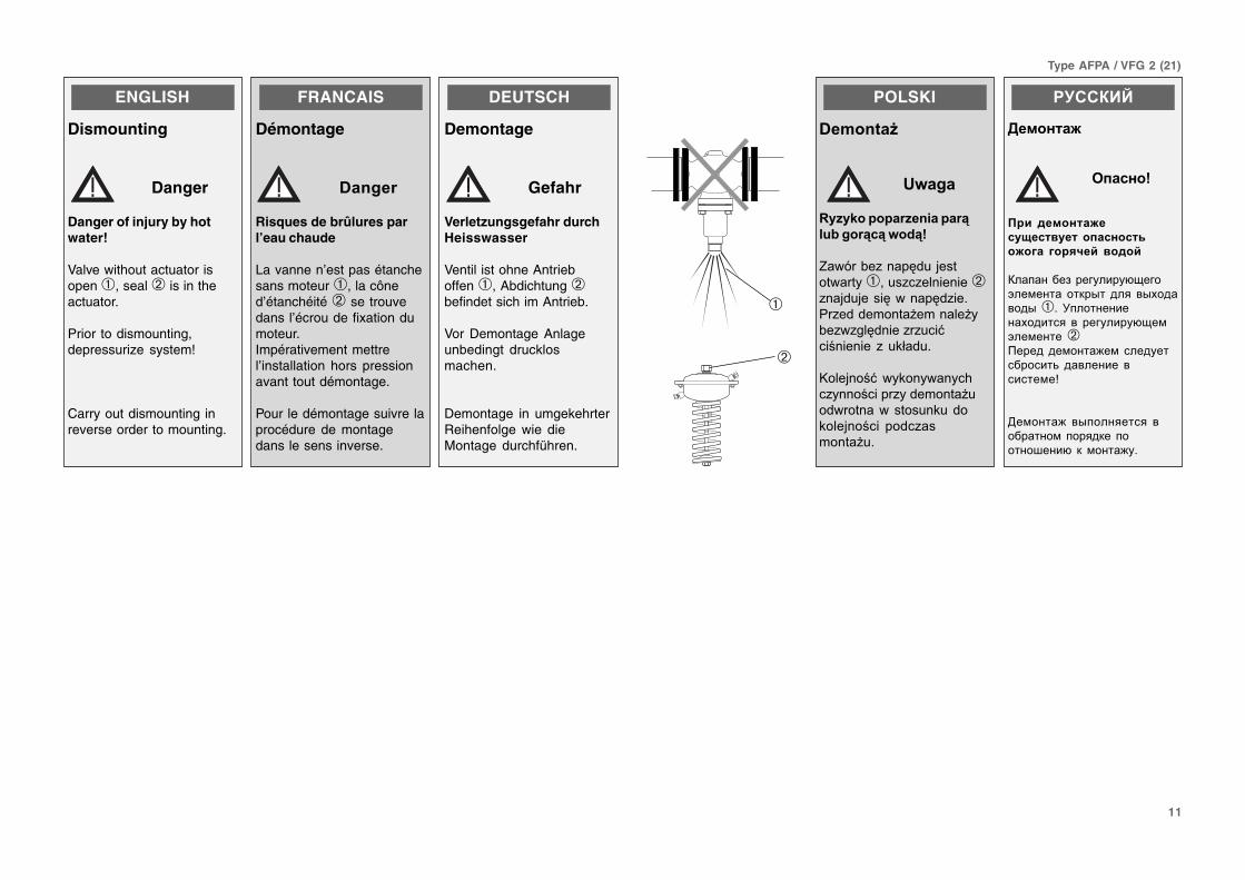
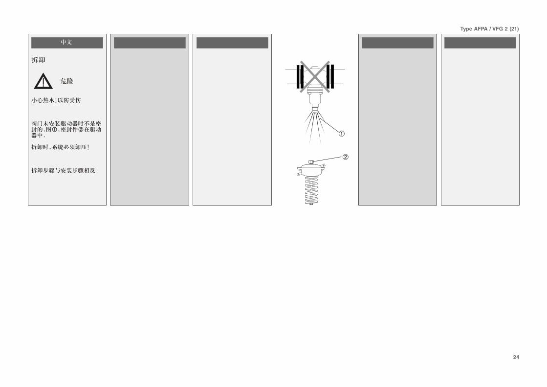
Dismounting
Danger
Danger of injury by hotwater!
Valve without actuator isopen ➀, seal ➁ is in theactuator.
Prior to dismounting,depressurize system!
Carry out dismounting inreverse order to mounting.
FRANCAIS
Démontage
'���
Risques de brûlures parl’eau chaude
La vanne n’est pas étanchesans moteur ➀, la côned’étanchéité ➁ se trouvedans l’écrou de fixation dumoteur.Impérativement mettrel’installation hors pressionavant tout démontage.
Pour le démontage suivre laprocédure de montagedans le sens inverse.
DEUTSCH
Demontage
Gefahr
Verletzungsgefahr durchHeisswasser
Ventil ist ohne Antrieboffen ➀, Abdichtung ➁befindet sich im Antrieb.
Vor Demontage Anlageunbedingt drucklosmachen.
Demontage in umgekehrterReihenfolge wie dieMontage durchführen.
POLSKI
'�"���&
*��
=��� �����������4
#�����4�4����4>
$���!�" ��0&�,���������➀���"�"�� �� ��➁" �,&�,���0� ��0&"��9�"�&&�-� ����- �����!�"�"��0& ��""���:��� �� �� "�%2�&�9
B���, ��:��%� ��� ��.�"� �����"�&�-� �����&��� ������� %�&�%���, ���� ��&�"��-� ����9
�������
�� ���
���� �3
��� ��� ����!$���!������ �������#�� #��'0� ����0
%��������#���� ��� 0.���1��&����� ��"�-�� ���� �-!������-�➀?� C�����������!������� �� ��� ��� 0.�&1��&�����➁ �������&����)�&� ���� ���������3� ��������� ������&�S
,�&����)� �-���������� ��������&������"��������F���0� "�&����) ?
➁
➀
12
Type AFPA / VFG 2 (21)
FRANCAIS
Contrôle d’étanchéitéet de pression
Une augmentationde pression doits’effectuer d’une
manière homogène auxraccordements +/- ➀.
Attention: La vanne estfermée sans pression, elles’ouvre lorsque la pressiondifférentielle augmente
En aucun cas, il ne fautlaisser croître la pression –au-dessus de la pression +.Respecter les pressionsmax. autorisées, voir ci-dessous.En cas de non-respect, lerégulateur de pression ou lavanne peuvent êtreendommagés.
Pression de contrôle max.(bar) avec conduites decommande raccordées
AFPA 80 250 630cm2
bar 25 25 16
Avec des pressions decontrôle plus élevées, lesconduites de commandedoivent être retirées ➁.
Fermer les raccordementsavec des bouchons G ¼ISO 228 ➀.
Respecter la pressionnominale ➂ de la vanne. Lapression de contrôle max.est 1,5 x PN
DEUTSCH
Dichtheits-,Druckprüfung
Druckerhöhungmuss am +/– An-schluss ➀ gleich-mäßig erfolgen.
Achtung: Das Ventil istdrucklos geschlossen, esöffnet bei steigendemDifferenzdruck.
Keinesfall –Druck über den+Druck ansteigen lassen.Max. zulässige Drückebeachten, siehe unten.
Nichtbeachtung kann zuSchäden am Antrieb oderVentil führen.
Max. Prüfdruck [bar] mitangeschlossenenSteuerleitungen
AFPA 80 250 630cm2
bar 25 25 16
Bei höheren Prüfdrückenmüssen die Steuerleitun-gen ➁ entfernt werden.
Die Anschlüsse ➀ mitStopfen G 1/4 ISO 228schließen.
Nenndruck ➂ des Ventilsbeachten. Max. Prüfdruckist 1,5 x PN.
POLSKI
$5����7���������
�����#��7��@�� �� �� -���!�: ���� ������& ��"� � �
��&23�"� ���.�?@;���?1;➀9
*��A$���,���!�"��� �� ���� "�-% �0�� ���������0�"��� 3��,�� ������ ���9
@�� �� �� �K>L ��&� ��-����"�����"�:���������� �� �� � KML9
$����:����0 �-�I9&����"�"�� � ��� �� ��� ���"�� ���,9
8���"���"��� ��������"���-��������&���: " ��"�"� �� ��0&� ��!"����9
%BC���7�������5����D�E
�������34������)�� �)
�"��#�����)
AFPA 80 250 630cm2
bar 25 25 16
+������"��.��� �����! ��. ������&23�"�:�%� �-��������& ����3��➁9=����"�%�%���:"�����%�-�"��� ��-���'��5C=��4➀
C���&"�:�����: ��� �� �� �-� �� ���N � %������"����9%B���7�������5�����������.</�B�$�
�������
���"�� �� ���' ������#���' ����
,�������� �� ��9"�!��������������&� �3��-!� �� ��"
456,7�➀� ���)������-F��3������������?
��!��� �.� ����� ������� ��������� "�����#�"�-�;����������-F��������������������������"�-������?
>�� ����9����3� ��������� ��F� �����T+U� �-F�������������F� �����T57� ��� ������?
����0���3�&�"�?� ��� ���&����������;� �&?� ��)�?
>�����0������ 1��!���������<�&�)��� ��������� "����&"��"������������� ��� 0.���� 1��&����?
����/� ���"����� ����� �� 8��9� ������(' "�����!��� "��� �!�����
AFPA 80 250 630cm2
bar 25 25 16
Q� �� 9��� ���-�����3������������� �-F�;� "�#������� ��������;� ����!���&�� ����3�&� �3��-�� �� �"��➁?
:�"�-�3� ��#3���-����������� #��� F"�&������'NVW�4�➀?
��9����� #��9����� �������������������� "��� ��� "������➂?�����/� ���"����� ����� ������������ *:+� �;�/
ENGLISH
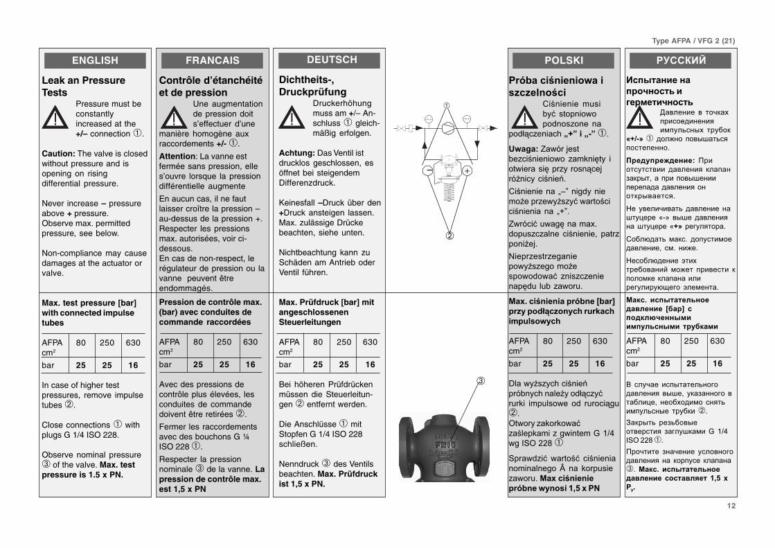
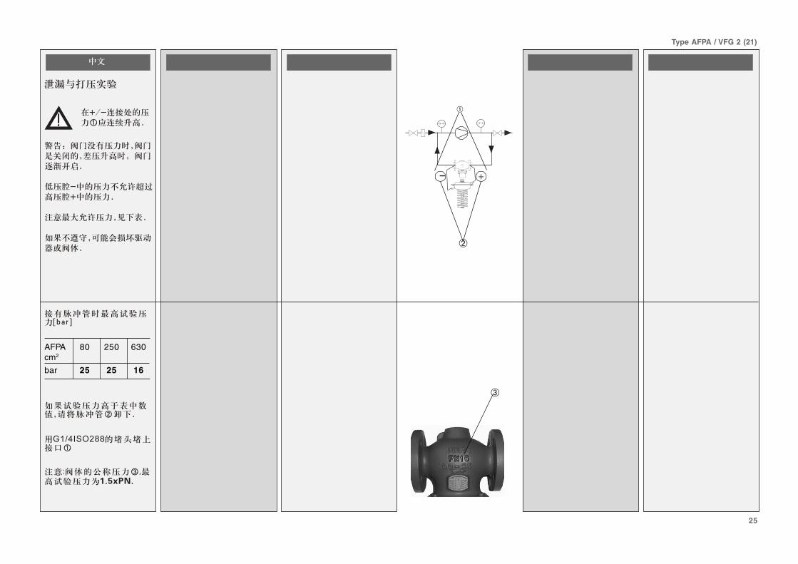
Leak an PressureTests
Pressure must beconstantlyincreased at the+/– connection ➀.
Caution: The valve is closedwithout pressure and isopening on risingdifferential pressure.
Never increase – pressureabove + pressure.Observe max. permittedpressure, see below.
Non-compliance may causedamages at the actuator orvalve.
Max. test pressure [bar]with connected impulsetubes
AFPA 80 250 630cm2
bar 25 25 16
In case of higher testpressures, remove impulsetubes ➁.
Close connections ➀ withplugs G 1/4 ISO 228.
Observe nominal pressure➂ of the valve. Max. testpressure is 1.5 x PN.
➂
➁
- +
➀
13
Type AFPA / VFG 2 (21)
FRANCAIS
Remplissage del’installation, mise enservice
La pression retour➀ ne doit pasdépasser la
pression aller ➁
En cas de non-respect, lerégulateur de pression ou lavanne peuvent êtreendommagés.
1. Ouvrir lentement lesrobinets d’arrêt ➅
2. Ouvrir lentement lesrobinets d’arrêt ➆
Mise hors service
1. Fermer lentement lesrobinets d’arrêt ➅.
2. Fermer lentement lesrobinets d’arrêt ➆
DEUTSCH
Füllung der Anlage,Inbetriebnahme
Der Rücklaufdruck➀ darf den Vor-laufdruck ➁ nicht
überschreiten.
Nichtbeachtung kann zuSchäden am Antrieb führen.
1. Absperrarmatur ➅langsam öffnen.
2. Absperrarmatur ➆langsam öffnen.
Außerbetriebnahme
1. Absperrarmatur ➅langsam schließen.
2. Absperrarmatur ➆langsam schließen.
POLSKI
���3������� 3��C
$������
���)�"�����C@�� �� �������3������� �-➀ ��
-���!�:����"� �������3�� "�����,3��-➁9
8���"���"��� ��������"���-��������&���: " ��"�"� �� ��0&� ��!"����9
�9 ����������"�:"����&�� �,3��➅9
�9����������"�:"����&�� �,3��➆9
���"����� 3��C
�9 ������"�-% 3:"����&�� �,3��➅9
�9 ������"�-% 3:"����&�� �,3��➆9
�������
<���� �������"/��"0����!��
,�������� ��� ���������������"�������➀������)��� ����-F��3
������������"�������➁?
>�����0������ 1���������������&�)��� ��������"�����&"��"������������� ��� 0.���� 1��&����?
�? (�������� ��"�-�3#�����-<�"������➅?
? (�������� ��"�-�3#�����-<�"������➆?
����(' �������"
�? (�������� #�"�-�3#�����-<�"������➅?
? (�������� #�"�-�3#�����-<�"������➆?
ENGLISH
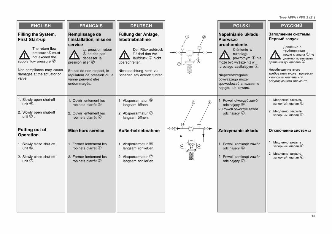
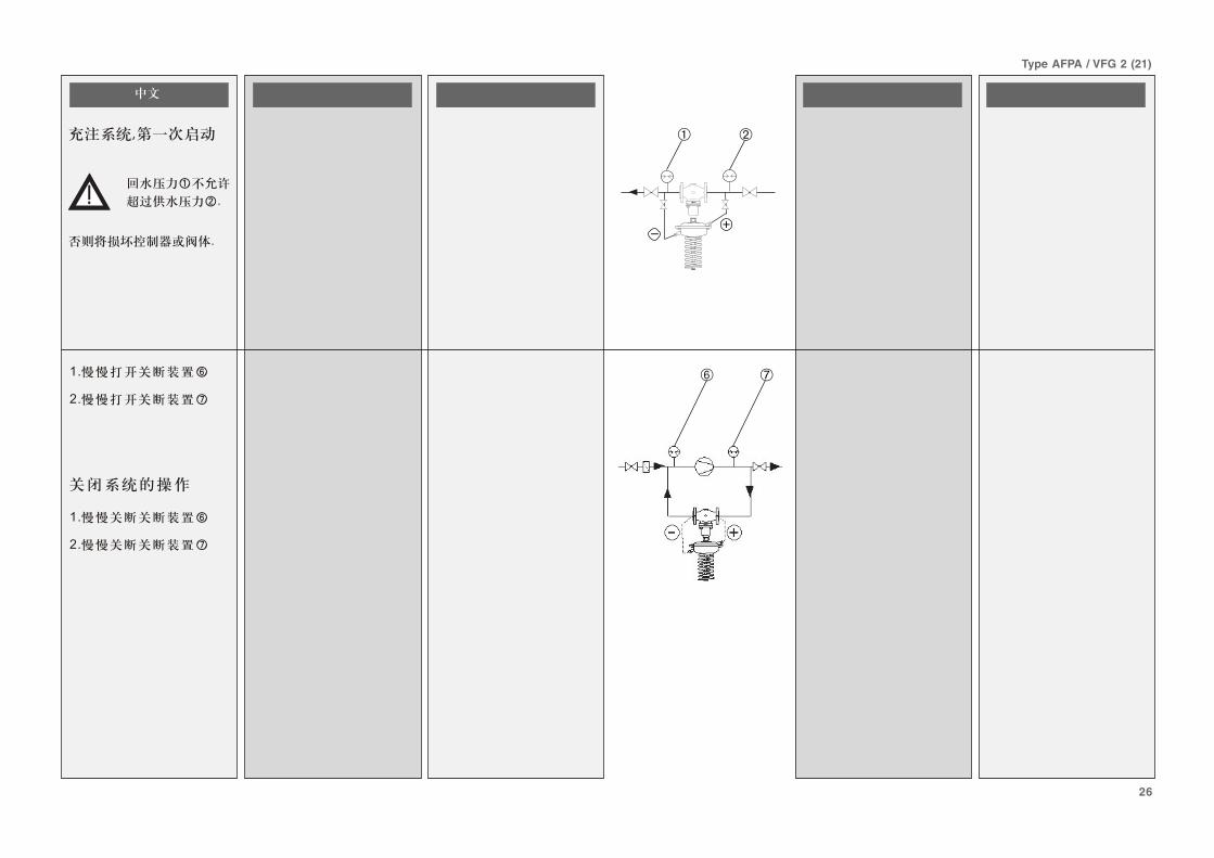
Filling the System,First Start-up
The return flowpressure ➀ mustnot exceed the
supply flow pressure ➁.
Non-compliance may causedamages at the actuator orvalve.
1. Slowly open shut-offunit ➅.
2. Slowly open shut-offunit ➆ .
Putting out ofOperation
1. Slowly close shut-offunit ➅.
2. Slowly close shut-offunit ➆.
–+
➁➀
➆➅
14
Type AFPA / VFG 2 (21)
➉
FRANCAIS
Réglage de lapression différentielle
Plage de réglage, voirplaque signalétique ➀
1. Mettre l’installation enservice, voir paragraphe«mise en service»
2. Mettre la pompe ➅ enservice
3. Observer l’indication depression ➆
La rotation à droite ➇réduit la valeur de consigne(détendre le ressort)
La rotation à gauche ➈augmente la valeur deconsigne (tendre le ressort)
Le régleur de valeur deconsigne ➉ peut êtreplombé
DEUTSCH
EinstellungDifferenzdruck
Sollwertbereich sieheTypenschild ➀.
1. Anlage in Betriebnehmen, siehe Abschnitt„Inbetriebnahme“.
2. Pumpe ➅ in Betriebnehmen.
3. Druckanzeigen ➆beachten.
Rechtsdrehung ➇ reduziertden Sollwert.(Feder entspannen,Zugefeder)
Linksdrehung ➈ erhöht denSollwert.(Feder spannen)
4. Der Sollwertsteller ➉kann plombiert werden.
POLSKI
��������#����(
5&�������7����C
$�%�� �����*���"��!���"%�" �-�� ���➀9
�9 D��.�-�:�%2�&>���"�"&"��2 K8���2 �� ���%2�&�9�����"����.�-�� ��L9
�9 D��.�-�: ��-�0➅9
#9 =!������:��%�"� ��-� �-����➆ 9
B0��:�����➇�����"- ��,�"� ��������� ������
B0��:�����➈�����"��0%�"� ��������� ������
8�%0�%� ������"�➉-���"����:"����-!��� �9
�������
=����0������������ ��
,����#��� ������<"�� "�#�����@��&����<������9"���� �������➀?
�? :�� ����3� �����& � ��&?��#����T:��������������&-;� ����-<#�� �"U�?
?� :�� ����3� ������➅?
$?�������3�#����"�#����&�&���&����� ➆� ?
������� ��<"�� ��� 9�����<�����"��➇ � ���)���#������&-<����������������?
������� ��<"�� ������9�����<� �����"��➈ ����9������ #������&-<����������������?
7�<"�� ������<"��➉�&�)���-�3� ����&��������?
ENGLISH
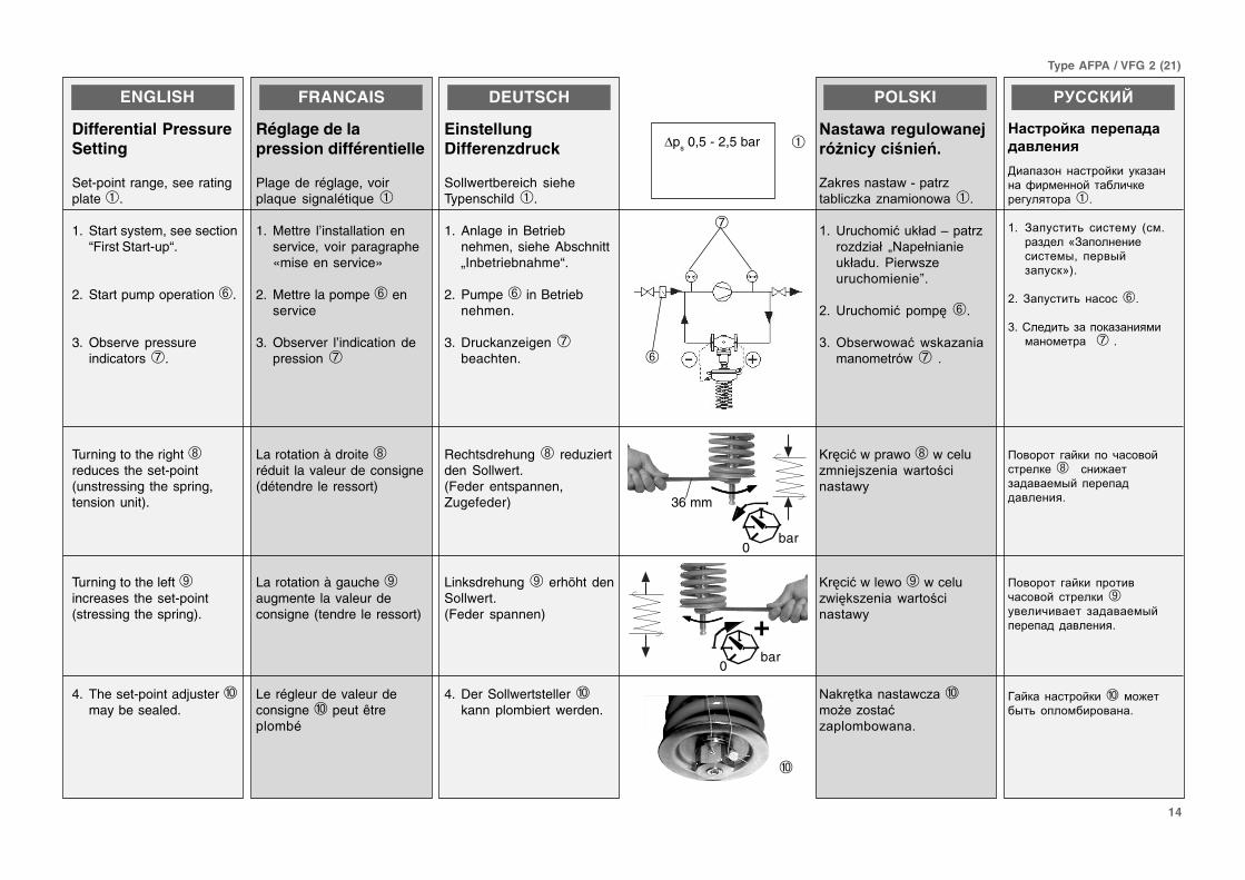
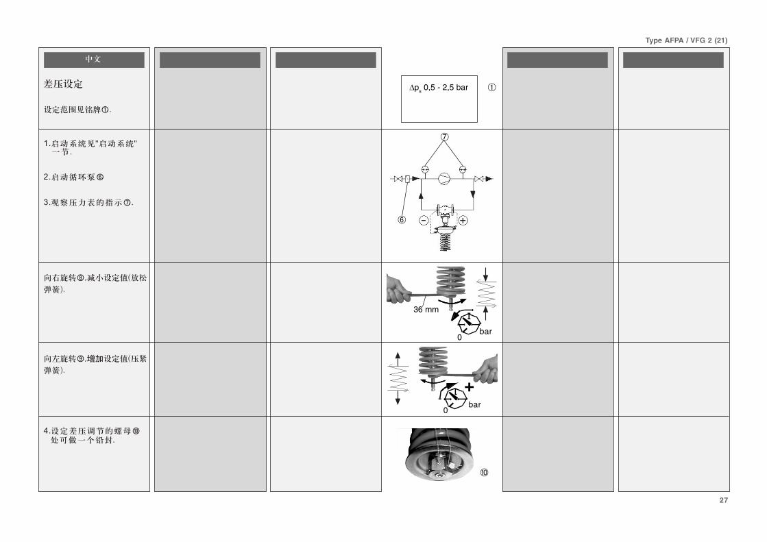
Differential PressureSetting
Set-point range, see ratingplate ➀.
1. Start system, see section“First Start-up“.
2. Start pump operation ➅.
3. Observe pressureindicators ➆.
Turning to the right ➇reduces the set-point(unstressing the spring,tension unit).
Turning to the left ➈increases the set-point(stressing the spring).
4. The set-point adjuster ➉may be sealed.
∆ps 0,5 - 2,5 bar ➀
36 mm
bar0
+0
bar
➆
➅
15
Type AFPA / VFG 2 (21)
16
17
18
18
18
19
20
21
23
23
24
25
26
26
27
16
Type AFPA / VFG 2 (21)
17
Type AFPA / VFG 2 (21)
DN 150 - 250tmax = 200 °C
AF (2x)*
VFG 2 (21)DN 150 - 250
V1, V2 (630 cm2)
AFPA
DN 15 - 125tmax = 200 °C
VFG 2 (21)DN 15 - 125
AF (2x)*
AFPA
DN 150 - 250tmax = 140 °C
VFG 2 (21)DN 150 - 250
AF (2x)*
VFG 2 (21)DN 15 - 125
AFPA
DN 15 - 125tmax = 150 °C
AF (2x)*
AFPA
2 x
V1, V2 (630 cm2)
2 x
18
Type AFPA / VFG 2 (21)
➀
19
Type AFPA / VFG 2 (21)
➂
➁
➀
20
Type AFPA / VFG 2 (21)
➀➁
46 mm
100 Nm
DN 150 - 250
➁

21
Type AFPA / VFG 2 (21)
➀
G 1/4AF
➁
➂
➃
➄
➂
54
22
Type AFPA / VFG 2 (21)
➁
➀
➂
➄
➃
➅
➆
➇
23
Type AFPA / VFG 2 (21)
M
➉➈
➀
N100
°C
0
�
��
�
��
�
�
�
VFG 2 (21) DN 15 - 125 VFG 2 (21) DN 150 - 250
VFG 2 DN 150 - 250tmax 200 °C AFPA
mm
100°C
0
VFG 2 (21) DN 15 20 25 32 40 50 65 80 100 125 150 200 250
L 130 150 160 180 200 230 290 310 350 400 480 600 730
Bm m
212 212 238 238 240 240 275 275 380 380 326 354 404
kg 7 9 10 13 17 22 33 41 60 79 85 145 228
VFG 2, tmax 200 °C
B1 m m – – – – – – – – – – 630 855 1205
kg 140 210 300
AFPA cm2 80 250 630
A 172 263 380
H 430 470 520
kg 7.5 13 28
24
Type AFPA / VFG 2 (21)
➁
➀
25
Type AFPA / VFG 2 (21)
➂
➁
- +
➀
AFPA 80 250 630cm2
bar 25 25 16
26
Type AFPA / VFG 2 (21)
–+
➁➀
➆➅
27
Type AFPA / VFG 2 (21)
➉
∆ps 0,5 - 2,5 bar ➀
36 mm
➆
➅
bar0
+0
bar


