Download - Lecture 14 Introduction to Earthquake Resistant Design of RC Structures (Part I)_2011.pdf

7/27/2019 Lecture 14 Introduction to Earthquake Resistant Design of RC Structures (Part I)_2011.pdf
http://slidepdf.com/reader/full/lecture-14-introduction-to-earthquake-resistant-design-of-rc-structures-part 1/57
Department of Civil Engineering, University of Engineering and Technology Peshawar, Pakistan
Prof. Dr. Qaisar Ali CE 5115 Advance Design of Reinforced Concrete Structures Fall 2011
Lecture-14
Introduction to Earthquake
Resistant Design of RC
Structures (Part I)
By: Prof Dr. Qaisar Ali
Civil Engineering Department
UET Peshawar
1
Department of Civil Engineering, University of Engineering and Technology Peshawar, Pakistan
Prof. Dr. Qaisar Ali CE 5115 Advance Design of Reinforced Concrete Structures Fall 2011
Topics
Introduction
How Architectural Features Affect Buildings During
Earthquakes
Earthquake Design Philosophy
Seismic Loading Criteria
Analysis for Seismic Loads
Approximate Lateral Load Analysis (Portal method)
2
7/27/2019 Lecture 14 Introduction to Earthquake Resistant Design of RC Structures (Part I)_2011.pdf
http://slidepdf.com/reader/full/lecture-14-introduction-to-earthquake-resistant-design-of-rc-structures-part 2/57
Department of Civil Engineering, University of Engineering and Technology Peshawar, Pakistan
Prof. Dr. Qaisar Ali CE 5115 Advance Design of Reinforced Concrete Structures Fall 2011
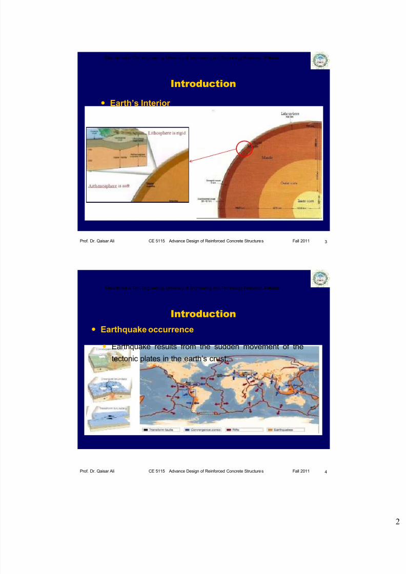
Introduction
Earth’s Interior
3
Department of Civil Engineering, University of Engineering and Technology Peshawar, Pakistan
Prof. Dr. Qaisar Ali CE 5115 Advance Design of Reinforced Concrete Structures Fall 2011
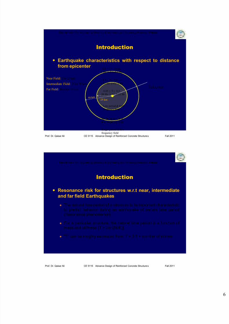
Introduction
Earthquake occurrence
Earthquake results from the sudden movement of the
tectonic plates in the earth’s crust.
4

7/27/2019 Lecture 14 Introduction to Earthquake Resistant Design of RC Structures (Part I)_2011.pdf
http://slidepdf.com/reader/full/lecture-14-introduction-to-earthquake-resistant-design-of-rc-structures-part 3/57
Department of Civil Engineering, University of Engineering and Technology Peshawar, Pakistan
Prof. Dr. Qaisar Ali CE 5115 Advance Design of Reinforced Concrete Structures Fall 2011
Introduction
Seismic Events around the globe
Mostly takes place at boundaries of Tectonic plates
5
Dots
represents an
earthquake
Department of Civil Engineering, University of Engineering and Technology Peshawar, Pakistan
Prof. Dr. Qaisar Ali CE 5115 Advance Design of Reinforced Concrete Structures Fall 2011
Introduction
Effect of Earthquake
The movement, taking place at the fault lines, causes
energy release which is transmitted through the earth in
the form of waves. These waves reach the structure
causing shaking.
6

7/27/2019 Lecture 14 Introduction to Earthquake Resistant Design of RC Structures (Part I)_2011.pdf
http://slidepdf.com/reader/full/lecture-14-introduction-to-earthquake-resistant-design-of-rc-structures-part 4/57
Department of Civil Engineering, University of Engineering and Technology Peshawar, Pakistan
Prof. Dr. Qaisar Ali CE 5115 Advance Design of Reinforced Concrete Structures Fall 2011
Introduction
Types of Waves Generated Due to Earthquake
7
Body Waves Surface Waves
Department of Civil Engineering, University of Engineering and Technology Peshawar, Pakistan
Prof. Dr. Qaisar Ali CE 5115 Advance Design of Reinforced Concrete Structures Fall 2011
Displacement due to Earthquake
Introduction

7/27/2019 Lecture 14 Introduction to Earthquake Resistant Design of RC Structures (Part I)_2011.pdf
http://slidepdf.com/reader/full/lecture-14-introduction-to-earthquake-resistant-design-of-rc-structures-part 5/57
Department of Civil Engineering, University of Engineering and Technology Peshawar, Pakistan
Prof. Dr. Qaisar Ali CE 5115 Advance Design of Reinforced Concrete Structures Fall 2011
Introduction
Horizontal and Vertical Shaking
Earthquake causes shaking of the ground in all three directions.
The structures designed for gravity loading (DL+LL) will be
normally safe against vertical component of ground shaking.
The vertical acceleration during ground shaking either adds to
or subtracts from the acceleration due to gravity.
Department of Civil Engineering, University of Engineering and Technology Peshawar, Pakistan
Prof. Dr. Qaisar Ali CE 5115 Advance Design of Reinforced Concrete Structures Fall 2011
Introduction
Horizontal and Vertical Shaking
The structures are normally designed for horizontal shaking
to minimize the effect of damages due to earthquakes.
7/27/2019 Lecture 14 Introduction to Earthquake Resistant Design of RC Structures (Part I)_2011.pdf
http://slidepdf.com/reader/full/lecture-14-introduction-to-earthquake-resistant-design-of-rc-structures-part 6/57
Department of Civil Engineering, University of Engineering and Technology Peshawar, Pakistan
Prof. Dr. Qaisar Ali CE 5115 Advance Design of Reinforced Concrete Structures Fall 2011
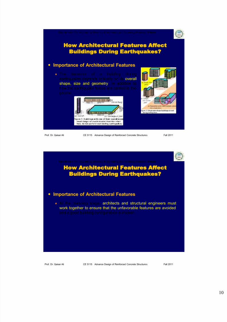
Introduction
Earthquake characteristics with respect to distance
from epicenter
0.05 ≤ T ≤ 0.3
20 Hz ≥ f ≥ 3.33 Hz
Low period & high
frequency field
0.3 ≤ T ≤ 1.0 sec
3.33 Hz ≥ f ≥ 1 Hz
1.0 ≤ T ≤ 10 sec
25 km
Large period & low
frequency field
Moderate period &
low frequency field
Epicenter
1 Hz ≥ f ≥ 0.1 Hz
Near Field: 0 to 25 km
Intermediate Field: 25 to 50 km
Far Field: Beyond 50 km
Department of Civil Engineering, University of Engineering and Technology Peshawar, Pakistan
Prof. Dr. Qaisar Ali CE 5115 Advance Design of Reinforced Concrete Structures Fall 2011
Introduction
Resonance risk for structures w.r.t near, intermediate
and far field Earthquakes
The natural time period of a structure is its important characteristic
to predict behavior during an earthquake of certain time period
(Resonance phenomenon).
For a particular structure, the natural time period is a function of
mass and stiffness {T = 2π√(M/K)}
“T” can be roughly estimated from: T = 0.1 × number of stories

7/27/2019 Lecture 14 Introduction to Earthquake Resistant Design of RC Structures (Part I)_2011.pdf
http://slidepdf.com/reader/full/lecture-14-introduction-to-earthquake-resistant-design-of-rc-structures-part 7/57
Department of Civil Engineering, University of Engineering and Technology Peshawar, Pakistan
Prof. Dr. Qaisar Ali CE 5115 Advance Design of Reinforced Concrete Structures Fall 2011
Introduction
Resonance risk for structures w.r.t near, intermediate
and far field Earthquakes
Low rise
Structure
(upto 3 stories)
Epicenter
Medium rise
Structure
(upto 5 stories)
High rise
Structure
(Above 5 stories)
Department of Civil Engineering, University of Engineering and Technology Peshawar, Pakistan
Prof. Dr. Qaisar Ali CE 5115 Advance Design of Reinforced Concrete Structures Fall 2011
Introduction
Earthquake Recording
Seismograph
Using multiple seismographs
around the world, accurate
location of the epicenter of the
earthquake, as well as its
magnitude or size can bedetermined.
Working of seismograph shown
in figure.

7/27/2019 Lecture 14 Introduction to Earthquake Resistant Design of RC Structures (Part I)_2011.pdf
http://slidepdf.com/reader/full/lecture-14-introduction-to-earthquake-resistant-design-of-rc-structures-part 8/57
Department of Civil Engineering, University of Engineering and Technology Peshawar, Pakistan
Prof. Dr. Qaisar Ali CE 5115 Advance Design of Reinforced Concrete Structures Fall 2011
Introduction
Earthquake Recording
Richter Scale
In 1935, Charles Richter (US)
developed this scale.
The Richter scale is logarithmic,
So, a magnitude 5 Richter
measurement is ten times
greater than a magnitude 4;
while it is 10 x 10, or 100 times
greater than a magnitude 3measurement.
Department of Civil Engineering, University of Engineering and Technology Peshawar, Pakistan
Prof. Dr. Qaisar Ali CE 5115 Advance Design of Reinforced Concrete Structures Fall 2011
Introduction
Earthquake Recording
Some of the famous
earthquake records

7/27/2019 Lecture 14 Introduction to Earthquake Resistant Design of RC Structures (Part I)_2011.pdf
http://slidepdf.com/reader/full/lecture-14-introduction-to-earthquake-resistant-design-of-rc-structures-part 9/57
Department of Civil Engineering, University of Engineering and Technology Peshawar, Pakistan
Prof. Dr. Qaisar Ali CE 5115 Advance Design of Reinforced Concrete Structures Fall 2011
Introduction
Number of Earthquakes per year
Department of Civil Engineering, University of Engineering and Technology Peshawar, Pakistan
Prof. Dr. Qaisar Ali CE 5115 Advance Design of Reinforced Concrete Structures Fall 2011
Introduction
Seismic Zones
7/27/2019 Lecture 14 Introduction to Earthquake Resistant Design of RC Structures (Part I)_2011.pdf
http://slidepdf.com/reader/full/lecture-14-introduction-to-earthquake-resistant-design-of-rc-structures-part 10/57

7/27/2019 Lecture 14 Introduction to Earthquake Resistant Design of RC Structures (Part I)_2011.pdf
http://slidepdf.com/reader/full/lecture-14-introduction-to-earthquake-resistant-design-of-rc-structures-part 11/57
Department of Civil Engineering, University of Engineering and Technology Peshawar, Pakistan
Prof. Dr. Qaisar Ali CE 5115 Advance Design of Reinforced Concrete Structures Fall 2011
How Architectural Features Affect
Buildings During Earthquakes?
Other Undesirable Scenarios
Department of Civil Engineering, University of Engineering and Technology Peshawar, Pakistan
Prof. Dr. Qaisar Ali CE 5115 Advance Design of Reinforced Concrete Structures Fall 2011
How Architectural Features Affect
Buildings During Earthquakes?
Soft Storey
7/27/2019 Lecture 14 Introduction to Earthquake Resistant Design of RC Structures (Part I)_2011.pdf
http://slidepdf.com/reader/full/lecture-14-introduction-to-earthquake-resistant-design-of-rc-structures-part 12/57
Department of Civil Engineering, University of Engineering and Technology Peshawar, Pakistan
Prof. Dr. Qaisar Ali CE 5115 Advance Design of Reinforced Concrete Structures Fall 2011
Earthquake Design Philosophy
Performance level
Department of Civil Engineering, University of Engineering and Technology Peshawar, Pakistan
Prof. Dr. Qaisar Ali CE 5115 Advance Design of Reinforced Concrete Structures Fall 2011
Building Code of Pakistan
In Pakistan, the design criteria for earthquake loading are based
on design procedures presented in chapter 5, division II of
Building Code of Pakistan, seismic provision 2007 (BCP, SP
2007), which have been adopted from chapter 16, division II of
UBC-97 (Uniform Building Code), volume 2.
Seismic Loading Criteria

7/27/2019 Lecture 14 Introduction to Earthquake Resistant Design of RC Structures (Part I)_2011.pdf
http://slidepdf.com/reader/full/lecture-14-introduction-to-earthquake-resistant-design-of-rc-structures-part 13/57
Department of Civil Engineering, University of Engineering and Technology Peshawar, Pakistan
Prof. Dr. Qaisar Ali CE 5115 Advance Design of Reinforced Concrete Structures Fall 2011
Lateral Force Determination Procedures
The total design seismic force imposed by an earthquake on
the structure at its base is referred to as base shear “V” in the
UBC-97.
The design seismic force can be determined based on:
Dynamic lateral force procedure [sec. 1631, UBC-97 or sec. 5.31, BCP-2007].
Static lateral force procedure [sec. 1630.2, UBC-97 or Sec. 5.30.2, BCP 2007], and/or
Seismic Loading Criteria
Department of Civil Engineering, University of Engineering and Technology Peshawar, Pakistan
Prof. Dr. Qaisar Ali CE 5115 Advance Design of Reinforced Concrete Structures Fall 2011
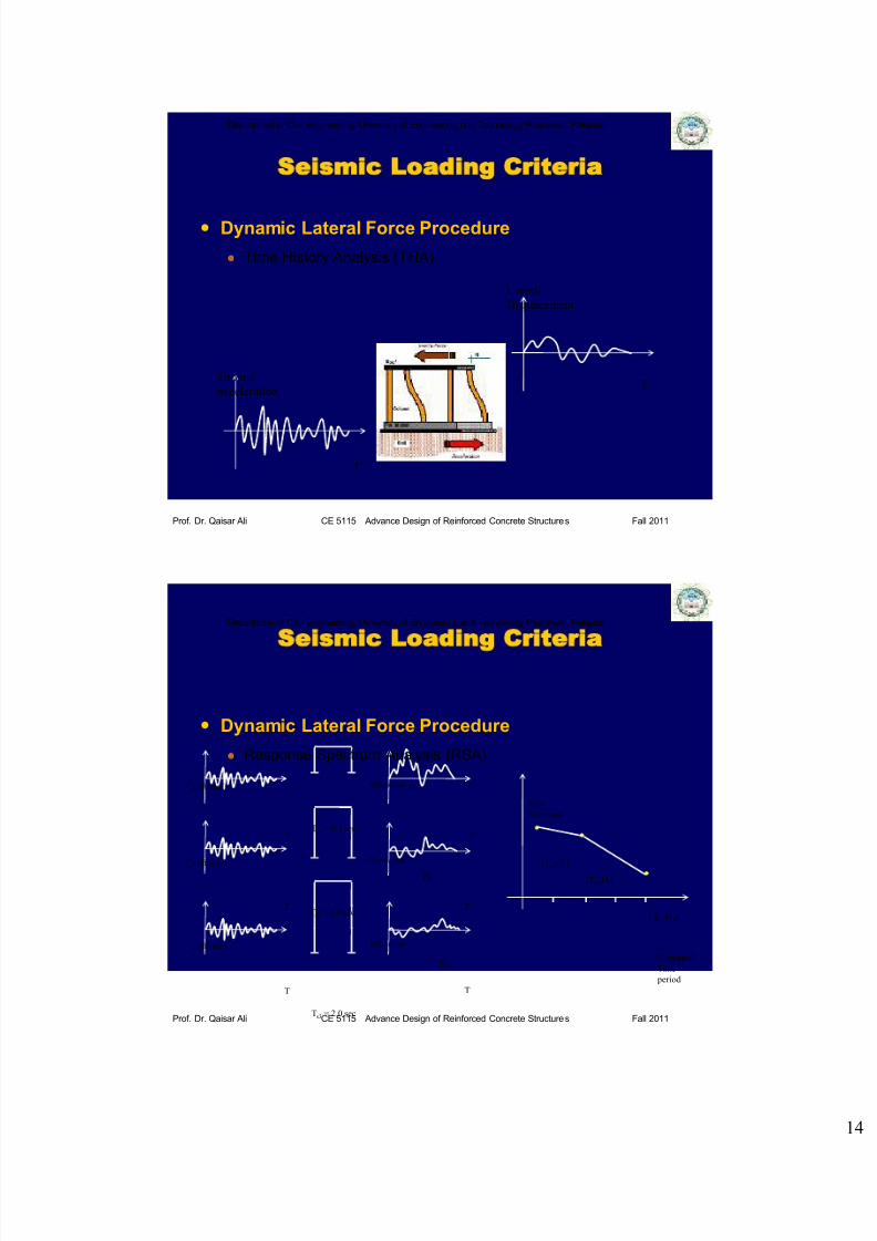
Dynamic Lateral Force Procedure
UBC-97 section 1631 include information on dynamic lateral force
procedures that involve the use of:
Time history analysis.
Response spectrum analysis.
The details of these methods are presented in sections 1631.5
and 1631.6 of the UBC-97.
Seismic Loading Criteria
7/27/2019 Lecture 14 Introduction to Earthquake Resistant Design of RC Structures (Part I)_2011.pdf
http://slidepdf.com/reader/full/lecture-14-introduction-to-earthquake-resistant-design-of-rc-structures-part 14/57
Department of Civil Engineering, University of Engineering and Technology Peshawar, Pakistan
Prof. Dr. Qaisar Ali CE 5115 Advance Design of Reinforced Concrete Structures Fall 2011
Dynamic Lateral Force Procedure
Time History Analysis (THA)
T
Ground
accelerationT
Lateral
Displacement
Seismic Loading Criteria
Department of Civil Engineering, University of Engineering and Technology Peshawar, Pakistan
Prof. Dr. Qaisar Ali CE 5115 Advance Design of Reinforced Concrete Structures Fall 2011
Dynamic Lateral Force Procedure
Response Spectrum Analysis (RSA)
a (ft/sec2)
T
Response
T
a (ft/sec2)
T
a (ft/sec2)
T
Response
Response
Ts1 = 0.3 sec
Ts2 = 1.0 sec
Ts3 = 2.0 sec
D1
D2
D3
(Ts1,D1)
(Ts2,D2)
(Ts3,D3)
Structural
Time
period
Peak
Response
T
T
Seismic Loading Criteria

7/27/2019 Lecture 14 Introduction to Earthquake Resistant Design of RC Structures (Part I)_2011.pdf
http://slidepdf.com/reader/full/lecture-14-introduction-to-earthquake-resistant-design-of-rc-structures-part 15/57
Department of Civil Engineering, University of Engineering and Technology Peshawar, Pakistan
Prof. Dr. Qaisar Ali CE 5115 Advance Design of Reinforced Concrete Structures Fall 2011
UBC-97 Response Spectrum Curve
(Acceleration vs. Time period)
Dynamic Lateral Force Procedure
Response Spectrum Analysis (RSA)
Seismic Loading Criteria
Department of Civil Engineering, University of Engineering and Technology Peshawar, Pakistan
Prof. Dr. Qaisar Ali CE 5115 Advance Design of Reinforced Concrete Structures Fall 2011
=
Seismic Loading Criteria
Static Lateral Force Procedure

7/27/2019 Lecture 14 Introduction to Earthquake Resistant Design of RC Structures (Part I)_2011.pdf
http://slidepdf.com/reader/full/lecture-14-introduction-to-earthquake-resistant-design-of-rc-structures-part 16/57
Department of Civil Engineering, University of Engineering and Technology Peshawar, Pakistan
Prof. Dr. Qaisar Ali CE 5115 Advance Design of Reinforced Concrete Structures Fall 2011
Static Lateral Force Procedure
The total design base shear (V) in a given direction can be
determined from the following formula:
V = (CνI/RT) W
Where,
Cν = Seismic coefficient (Table 16-R of UBC-97).
I = Seismic importance factor (Table 16-K of UBC-97 )
R = numerical coefficient representative of inherent over strength and
global ductility capacity of lateral force-resisting systems (Table 16-N
or 16-P).
W = the total seismic dead load defined in Section 1630.1.1.
Seismic Loading Criteria
Department of Civil Engineering, University of Engineering and Technology Peshawar, Pakistan
Prof. Dr. Qaisar Ali CE 5115 Advance Design of Reinforced Concrete Structures Fall 2011
Static Lateral Force Procedure
The total design base need not exceed [ V = (2.5CaI/R) W ]
Where, Ca = Seismic coefficient (Table 16-Q of UBC-97)
The total design base shear shall not be less than [ V = 0.11CaIW ]
In addition for seismic zone 4, the total base shear shall also not
be less [ V = (0.8ZNνI/R) W ]
Where, Nν
= near source factor (Table 16-T of UBC-97);
Z = Seismic zone factor (Table 16-I of UBC-97)
Seismic Loading Criteria
7/27/2019 Lecture 14 Introduction to Earthquake Resistant Design of RC Structures (Part I)_2011.pdf
http://slidepdf.com/reader/full/lecture-14-introduction-to-earthquake-resistant-design-of-rc-structures-part 17/57
Department of Civil Engineering, University of Engineering and Technology Peshawar, Pakistan
Prof. Dr. Qaisar Ali CE 5115 Advance Design of Reinforced Concrete Structures Fall 2011
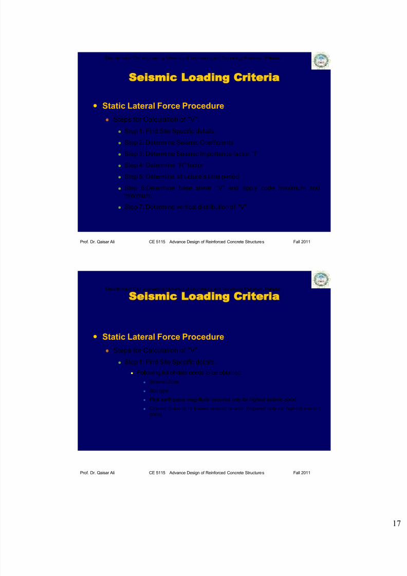
Static Lateral Force Procedure
Steps for Calculation of “V”:
Step 1: Find Site Specific details.
Step 2: Determine Seismic Coefficients
Step 3: Determine Seismic Importance factor “I”
Step 4: Determine “R” factor
Step 5: Determine structure’s time period
Step 6:Determine base shear “V” and apply code maximum and
minimum.
Step 7: Determine vertical distribution of “V”.
Seismic Loading Criteria
Department of Civil Engineering, University of Engineering and Technology Peshawar, Pakistan
Prof. Dr. Qaisar Ali CE 5115 Advance Design of Reinforced Concrete Structures Fall 2011
Static Lateral Force Procedure
Steps for Calculation of “V”:
Step 1: Find Site Specific details.
Following list of data needs to be obtained:
Seismic Zone
Soil type
Past earthquake magnitude (required only for highest seismic zone).
Closest distance to known seismic source (required only for highest seismic
zone).
Seismic Loading Criteria

7/27/2019 Lecture 14 Introduction to Earthquake Resistant Design of RC Structures (Part I)_2011.pdf
http://slidepdf.com/reader/full/lecture-14-introduction-to-earthquake-resistant-design-of-rc-structures-part 18/57
Department of Civil Engineering, University of Engineering and Technology Peshawar, Pakistan
Prof. Dr. Qaisar Ali CE 5115 Advance Design of Reinforced Concrete Structures Fall 2011
Static Lateral Force Procedure
Steps for Calculation of “V”:
Step 1: Site Specific details.
i. Seismic Zone
Source: BCP SP-2007
Seismic Loading Criteria
Department of Civil Engineering, University of Engineering and Technology Peshawar, Pakistan
Prof. Dr. Qaisar Ali CE 5115 Advance Design of Reinforced Concrete Structures Fall 2011
Static Lateral Force Procedure
Steps for Calculation of “V”:
Step 1: Find Site Specific details.
ii. Soil Type
As per UBC code, if soil type is not known, type SD shall be taken.
Seismic Loading Criteria

7/27/2019 Lecture 14 Introduction to Earthquake Resistant Design of RC Structures (Part I)_2011.pdf
http://slidepdf.com/reader/full/lecture-14-introduction-to-earthquake-resistant-design-of-rc-structures-part 19/57
Department of Civil Engineering, University of Engineering and Technology Peshawar, Pakistan
Prof. Dr. Qaisar Ali CE 5115 Advance Design of Reinforced Concrete Structures Fall 2011
Static Lateral Force Procedure
Steps for Calculation of “V”:
Step 1: Find Site Specific details.
iii. Past Earthquake magnitude: This is required only for seismic zone 4
to decide about seismic source type so that certain additional coefficients
can be determined.
iv. Distance to known seismic zone is also required to determine
additional coefficients for zone 4.
Seismic Loading Criteria
Department of Civil Engineering, University of Engineering and Technology Peshawar, Pakistan
Prof. Dr. Qaisar Ali CE 5115 Advance Design of Reinforced Concrete Structures Fall 2011
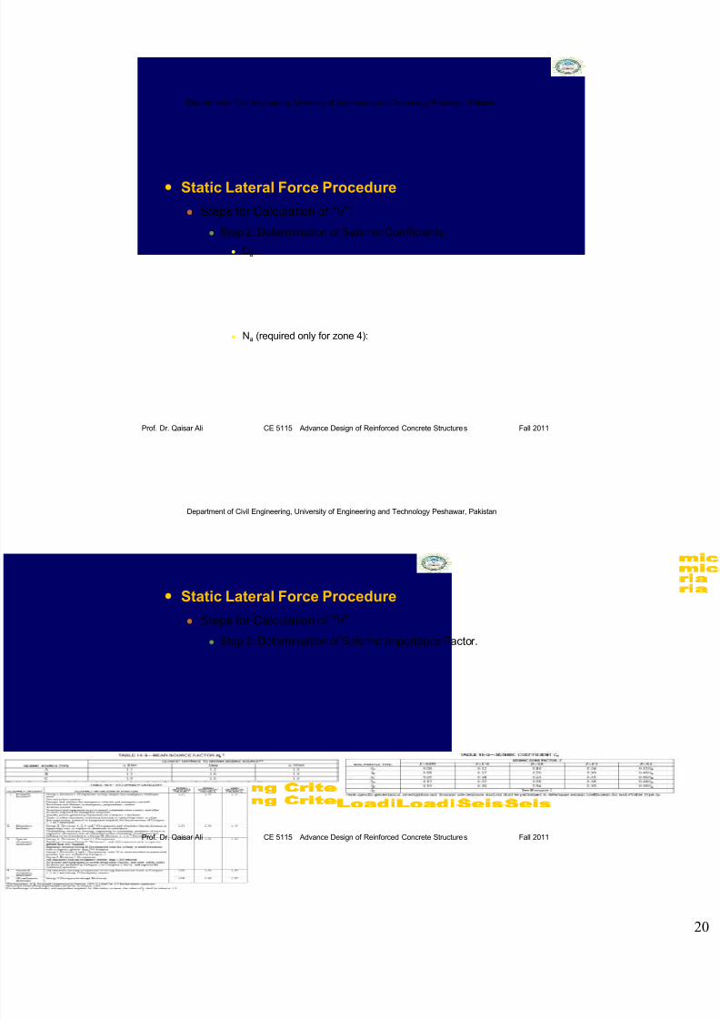
Static Lateral Force Procedure
Steps for Calculation of “V”:
Step 2: Determination of Seismic Coefficients.
Cv:
Nv (required only for zone 4):
Seismic Loading Criteria
7/27/2019 Lecture 14 Introduction to Earthquake Resistant Design of RC Structures (Part I)_2011.pdf
http://slidepdf.com/reader/full/lecture-14-introduction-to-earthquake-resistant-design-of-rc-structures-part 20/57
Department of Civil Engineering, University of Engineering and Technology Peshawar, Pakistan
Prof. Dr. Qaisar Ali CE 5115 Advance Design of Reinforced Concrete Structures Fall 2011
Static Lateral Force Procedure
Steps for Calculation of “V”:
Step 2: Determination of Seismic Coefficients.
Ca:
Na (required only for zone 4):
Seismic Loading Criteria
Department of Civil Engineering, University of Engineering and Technology Peshawar, Pakistan
Prof. Dr. Qaisar Ali CE 5115 Advance Design of Reinforced Concrete Structures Fall 2011
Static Lateral Force Procedure
Steps for Calculation of “V”:
Step 3: Determination of Seismic Importance Factor.
Seismic Loading Criteria

7/27/2019 Lecture 14 Introduction to Earthquake Resistant Design of RC Structures (Part I)_2011.pdf
http://slidepdf.com/reader/full/lecture-14-introduction-to-earthquake-resistant-design-of-rc-structures-part 21/57
Department of Civil Engineering, University of Engineering and Technology Peshawar, Pakistan
Prof. Dr. Qaisar Ali CE 5115 Advance Design of Reinforced Concrete Structures Fall 2011
Static Lateral Force Procedure
Steps for Calculation of “V”:
Step 4: Determination of “R” Factor.
R factor basically reduces base shear “V” to make the system
economical. However the structure will suffer some damage as explained
in the earthquake design philosophy.
R factor depends on overall structural response of the structure under
lateral loading.
For structures exhibiting good performance, R factor will be high.
Seismic Loading Criteria
Department of Civil Engineering, University of Engineering and Technology Peshawar, Pakistan
Prof. Dr. Qaisar Ali CE 5115 Advance Design of Reinforced Concrete Structures Fall 2011
Static Lateral Force Procedure
Steps for Calculation of “V”:
Step 4: Determination of “R” Factor.
Seismic Loading Criteria

7/27/2019 Lecture 14 Introduction to Earthquake Resistant Design of RC Structures (Part I)_2011.pdf
http://slidepdf.com/reader/full/lecture-14-introduction-to-earthquake-resistant-design-of-rc-structures-part 22/57
Department of Civil Engineering, University of Engineering and Technology Peshawar, Pakistan
Prof. Dr. Qaisar Ali CE 5115 Advance Design of Reinforced Concrete Structures Fall 2011
Static Lateral Force Procedure
Steps for Calculation of “V”:
Step 5: Determination of structure’s time period.
Structural Period (By Method A, UBC 97): For all buildings, the value T
may be approximated from the following formula:
T = Ct (hn)3/4
Where,
Ct = 0.035 (0.0853) for steel moment-resisting frames.
Ct = 0.030 (0.0731) for reinforced concrete moment-resisting frames and
eccentrically braced frames.
Ct = 0.020 (0.0488) for all other buildings.
hn = Actual height (feet or meters) of the building above the base to the nth level.
Seismic Loading Criteria
Department of Civil Engineering, University of Engineering and Technology Peshawar, Pakistan
Prof. Dr. Qaisar Ali CE 5115 Advance Design of Reinforced Concrete Structures Fall 2011
Static Lateral Force Procedure
Steps for Calculation of “V”:
Step 6: Determination of Base Shear (V).
Calculate base shear meeting the following criteria:
0.11CaIW ≤ V = (CνI/RT) W ≤ (2.5CaI/R) W
For zone 4, the total base shear shall also not be less than:
V = (0.8ZNνI/R) W
Seismic Loading Criteria

7/27/2019 Lecture 14 Introduction to Earthquake Resistant Design of RC Structures (Part I)_2011.pdf
http://slidepdf.com/reader/full/lecture-14-introduction-to-earthquake-resistant-design-of-rc-structures-part 23/57
Department of Civil Engineering, University of Engineering and Technology Peshawar, Pakistan
Prof. Dr. Qaisar Ali CE 5115 Advance Design of Reinforced Concrete Structures Fall 2011
Static Lateral Force Procedure
Steps for Calculation of “V”:
Step 7: Vertical Distribution of V to storeys.
The joint force at a particular level x of the structure is given as:
F x = (V – Ft)ω x h x /∑ωi hi (UBC sec. 1630.5)
{ i ranges from 1 to n, where n = number of stories }
Ft = Additional force that is applied to the top level (i.e., the roof) in
addition to the F x force at that level.
Ft = 0.07TV {for T > 0.7 sec}
Ft = 0 {for T ≤ 0.7 sec}
Seismic Loading Criteria
Department of Civil Engineering, University of Engineering and Technology Peshawar, Pakistan
Prof. Dr. Qaisar Ali CE 5115 Advance Design of Reinforced Concrete Structures Fall 2011
Static Lateral Force Procedure
Example: Calculation of “V” for E-W interior frame of the given
structure. Structure is located in Peshawar. Soil type is stiff.
46
25 ft 25 ft 25 ft 25 ft
20 ft
20 ft
20 ft
10 ft
10 ft
10 ft (floor to floor)
SDL = Nil
LL = 144 psf
SDL = NilLL = 144 psf
SDL = Nil
LL = 144 psf
f c′ = 4 ksi
f y = 60 ksi
Slab-
Beam
Frame
Structure
Seismic Loading Criteria

7/27/2019 Lecture 14 Introduction to Earthquake Resistant Design of RC Structures (Part I)_2011.pdf
http://slidepdf.com/reader/full/lecture-14-introduction-to-earthquake-resistant-design-of-rc-structures-part 24/57
Department of Civil Engineering, University of Engineering and Technology Peshawar, Pakistan
Prof. Dr. Qaisar Ali CE 5115 Advance Design of Reinforced Concrete Structures Fall 201147
Static Lateral Force Procedure
Example:
E-W interior frame
4 spans @ 25′-0″
3 s p a n s
@ 2 0 ′ - 0 ″
l 2 = 20′
Seismic Loading Criteria
Department of Civil Engineering, University of Engineering and Technology Peshawar, Pakistan
Prof. Dr. Qaisar Ali CE 5115 Advance Design of Reinforced Concrete Structures Fall 201148
Static Lateral Force Procedure
Example:
Step 1: Site specific details.
i. Seismic Zone:
From seismic zoning map of Pakistan, Peshawar lies in
seismic zone 2B (Z = 0.20)
Seismic Loading Criteria
7/27/2019 Lecture 14 Introduction to Earthquake Resistant Design of RC Structures (Part I)_2011.pdf
http://slidepdf.com/reader/full/lecture-14-introduction-to-earthquake-resistant-design-of-rc-structures-part 25/57
Department of Civil Engineering, University of Engineering and Technology Peshawar, Pakistan
Prof. Dr. Qaisar Ali CE 5115 Advance Design of Reinforced Concrete Structures Fall 201149
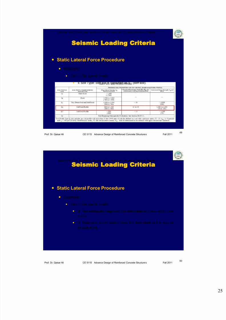
Static Lateral Force Procedure
Example:
Step 1: Site specific details.
ii. Soil Type: Stiff soil is classified as SD (stiff soil).
Seismic Loading Criteria
Department of Civil Engineering, University of Engineering and Technology Peshawar, Pakistan
Prof. Dr. Qaisar Ali CE 5115 Advance Design of Reinforced Concrete Structures Fall 201150
Static Lateral Force Procedure
Example:
Step 1: Site specific details.
iii. Past earthquake magnitude: Not determined as it required for zone
4 only.
iv. Distance to known seismic zone: Not determined as it is requiredfor zone 4 only.
Seismic Loading Criteria
7/27/2019 Lecture 14 Introduction to Earthquake Resistant Design of RC Structures (Part I)_2011.pdf
http://slidepdf.com/reader/full/lecture-14-introduction-to-earthquake-resistant-design-of-rc-structures-part 26/57
Department of Civil Engineering, University of Engineering and Technology Peshawar, Pakistan
Prof. Dr. Qaisar Ali CE 5115 Advance Design of Reinforced Concrete Structures Fall 201151
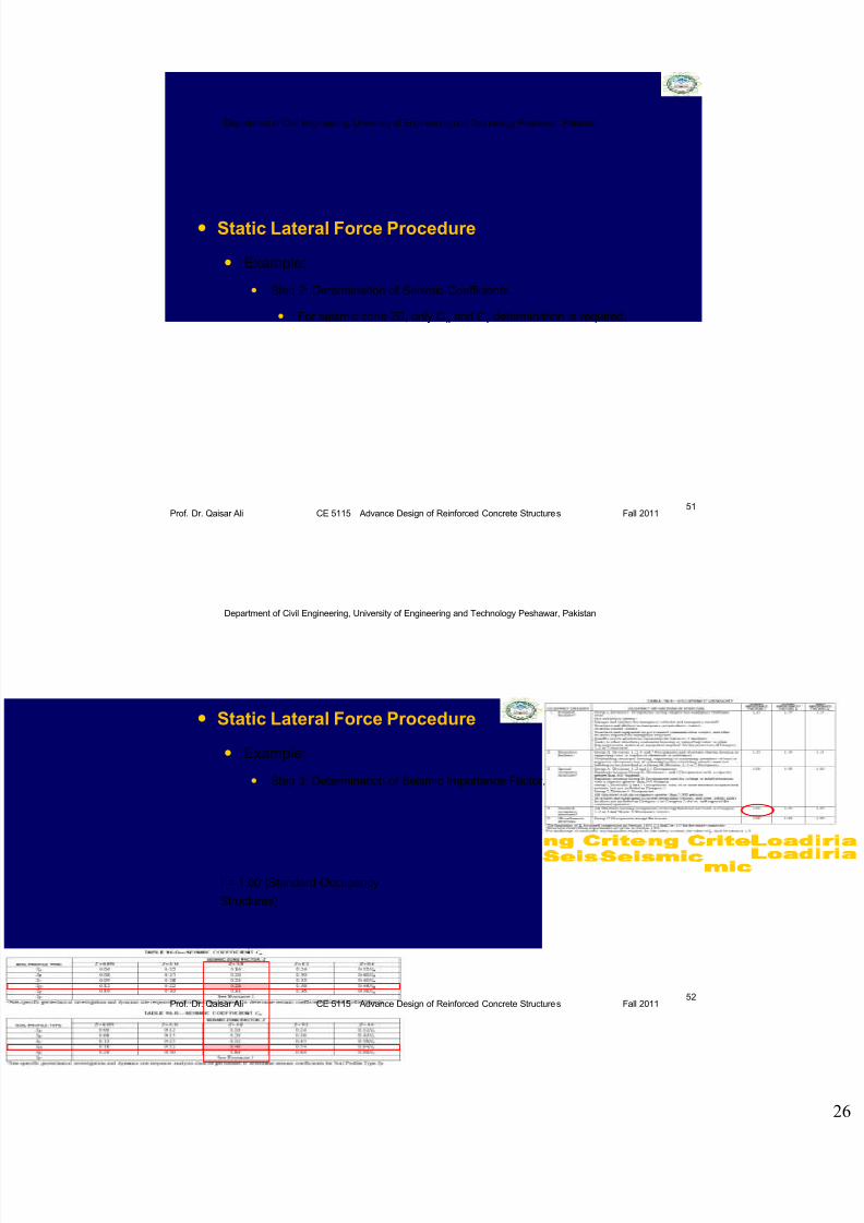
Static Lateral Force Procedure
Example:
Step 2: Determination of Seismic Coefficients.
For seismic zone 2B, only Ca and Cv determination is required.
Seismic Loading Criteria
Department of Civil Engineering, University of Engineering and Technology Peshawar, Pakistan
Prof. Dr. Qaisar Ali CE 5115 Advance Design of Reinforced Concrete Structures Fall 201152
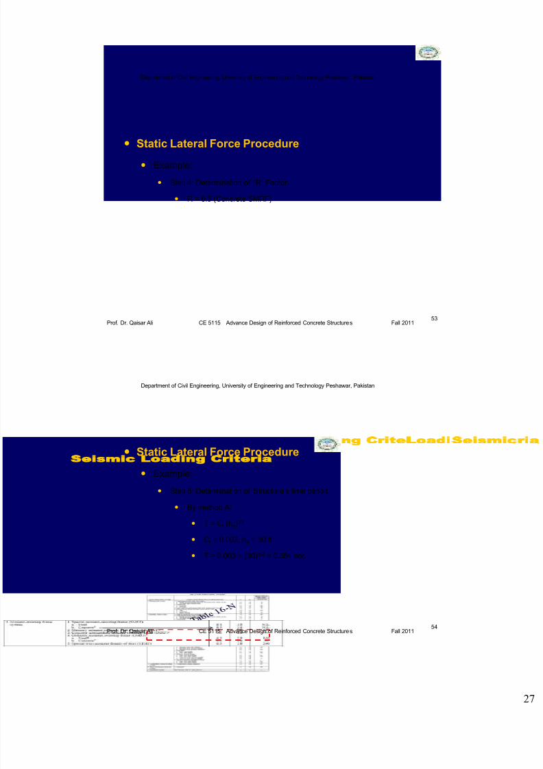
Static Lateral Force Procedure
Example:
Step 3: Determination of Seismic Importance Factor.
I = 1.00 (Standard Occupancy
Structures)
Seismic Loading Criteria
7/27/2019 Lecture 14 Introduction to Earthquake Resistant Design of RC Structures (Part I)_2011.pdf
http://slidepdf.com/reader/full/lecture-14-introduction-to-earthquake-resistant-design-of-rc-structures-part 27/57
Department of Civil Engineering, University of Engineering and Technology Peshawar, Pakistan
Prof. Dr. Qaisar Ali CE 5115 Advance Design of Reinforced Concrete Structures Fall 201153
Static Lateral Force Procedure
Example:
Step 4: Determination of “R” Factor.
R = 8.5 (Concrete SMRF)
Seismic Loading Criteria
Department of Civil Engineering, University of Engineering and Technology Peshawar, Pakistan
Prof. Dr. Qaisar Ali CE 5115 Advance Design of Reinforced Concrete Structures Fall 201154
Static Lateral Force Procedure
Example:
Step 5: Determination of Structure’s time period.
By method A:
T = Ct (hn)3/4
Ct = 0.003; hn = 30 ft
T = 0.003 × (30)3/4 = 0.384 sec
Seismic Loading Criteria

7/27/2019 Lecture 14 Introduction to Earthquake Resistant Design of RC Structures (Part I)_2011.pdf
http://slidepdf.com/reader/full/lecture-14-introduction-to-earthquake-resistant-design-of-rc-structures-part 28/57
Department of Civil Engineering, University of Engineering and Technology Peshawar, Pakistan
Prof. Dr. Qaisar Ali CE 5115 Advance Design of Reinforced Concrete Structures Fall 201155
Static Lateral Force Procedure
Example:
Step 6: Determination of base shear (V).
Base Shear (V) = {CvI/RT}W
W = 3 (w slab + w beams + w columns)E-W Frame
=3[(7/12)×20×(4×25)+{(14×13)/144}×(4×25)+5×{(14×14)/144}×10]× 0.15
= 3 × 204.33 = 613 kips
25 % floor live load will also be added up (for warehouses, see UBC
sec.1630.1.1.)
W = 613 + 0.25 0.144 20×(4×25) = 685 kips
Seismic Loading Criteria
Department of Civil Engineering, University of Engineering and Technology Peshawar, Pakistan
Prof. Dr. Qaisar Ali CE 5115 Advance Design of Reinforced Concrete Structures Fall 201156
Static Lateral Force Procedure
Example:
Step 6: Determination of base shear (V).
V = {CvI/RT}W = {0.40 1.00/ (8.5 0.384)} 685 = 83.94 kips
The total design base need not exceed the following:
V = (2.5CaI/R) W = {(2.5 × 0.28 × 1.00)/ (8.5)} × 685 = 56.41 kips, N.G.
The total design base shear shall not be less than the following:
V = 0.11CaIW = 0.11 × 0.28 × 1.00 × 685= 21.098 kips, O.K.
Therefore, V = 56.41 kip (8 % of seismic weight W)
Seismic Loading Criteria

7/27/2019 Lecture 14 Introduction to Earthquake Resistant Design of RC Structures (Part I)_2011.pdf
http://slidepdf.com/reader/full/lecture-14-introduction-to-earthquake-resistant-design-of-rc-structures-part 29/57
Department of Civil Engineering, University of Engineering and Technology Peshawar, Pakistan
Prof. Dr. Qaisar Ali CE 5115 Advance Design of Reinforced Concrete Structures Fall 201157
Static Lateral Force Procedure
Example:
Step 7: Vertical distribution of V to storeys.
F x = (V – Ft)ω x h x /∑ωi hi
∑ωi hi = 228 ×10 + 228×20 + 228×30 = 13680 kip
F1 = (56.41 – 0) × 228 × 10/ {(13680)} = 9.402 kip
Storey forces for other stories are given in table below:
Table Storey shears.
Level
xh x (ft) w x (kip) w xh x (ft-kip) w xh x /(Swihi) F x (kip)
3 30 228 6840 0.5 28.21
2 20 228 4560 0.33 18.61
1 10 228 2280 0.166 9.36
Swihi = 13680 Check SF x =V = 56.18 kip OK
Seismic Loading Criteria
Department of Civil Engineering, University of Engineering and Technology Peshawar, Pakistan
Prof. Dr. Qaisar Ali CE 5115 Advance Design of Reinforced Concrete Structures Fall 201158
Static Lateral Force Procedure
Example (Storey Forces):
Same forces will be obtained for other E-W interior frame because it has
same dimensions and loading conditions as of E-W interior frame
considered.
Half values shall be applied to E-W exterior frames.
Seismic Loading Criteria

7/27/2019 Lecture 14 Introduction to Earthquake Resistant Design of RC Structures (Part I)_2011.pdf
http://slidepdf.com/reader/full/lecture-14-introduction-to-earthquake-resistant-design-of-rc-structures-part 30/57
Department of Civil Engineering, University of Engineering and Technology Peshawar, Pakistan
Prof. Dr. Qaisar Ali CE 5115 Advance Design of Reinforced Concrete Structures Fall 201159
Static Lateral Force Procedure
Example (Storey Forces):
25 ft25 ft25 ft25 ft
20 ft
20 ft
20 ft
28.21 kips
18.61 kips
9.36 kips
Note: Base shear can
also be computed for
complete structure and
then can be divided to
different frames.
28.21 kips
18.61 kips
9.36 kips
14.1 kips
9.3 kips
4.68 kips
14.1 kips
9.3 kips
4.68 kips
Seismic Loading Criteria
Department of Civil Engineering, University of Engineering and Technology Peshawar, Pakistan
Prof. Dr. Qaisar Ali CE 5115 Advance Design of Reinforced Concrete Structures Fall 201160
Static Lateral Force Procedure
Class Activity: Calculate the base shear for the given frame.
Seismic Loading Criteria
200 kip
200 kipCv = 0.28I = 1.00
R = 8.5

7/27/2019 Lecture 14 Introduction to Earthquake Resistant Design of RC Structures (Part I)_2011.pdf
http://slidepdf.com/reader/full/lecture-14-introduction-to-earthquake-resistant-design-of-rc-structures-part 31/57
Department of Civil Engineering, University of Engineering and Technology Peshawar, Pakistan
Prof. Dr. Qaisar Ali CE 5115 Advance Design of Reinforced Concrete Structures Fall 201161
Seismic Loading Criteria
Static Lateral Force Procedure
Case Study 1: Comparison between the procedures of SAP2000 utilizing
automated lateral force feature and manually applied lateral loads for the
given frame.
The objectives of this study are:
To present the automated lateral force calculation feature of software
SAP2000.
To compare the manual lateral load application procedure with
automated load application feature of SAP2000.
Department of Civil Engineering, University of Engineering and Technology Peshawar, Pakistan
Prof. Dr. Qaisar Ali CE 5115 Advance Design of Reinforced Concrete Structures Fall 201162
Seismic Loading Criteria
Static Lateral Force Procedure
Case Study 1:
3D structure under study
SAP2000 3D Model
(20ft × 15 ft) panels
Seismic Zone: 2B
Soil Type: SD
Method A used for time period calculation
Mass source: SDL only

7/27/2019 Lecture 14 Introduction to Earthquake Resistant Design of RC Structures (Part I)_2011.pdf
http://slidepdf.com/reader/full/lecture-14-introduction-to-earthquake-resistant-design-of-rc-structures-part 32/57
Department of Civil Engineering, University of Engineering and Technology Peshawar, Pakistan
Prof. Dr. Qaisar Ali CE 5115 Advance Design of Reinforced Concrete Structures Fall 201163
Seismic Loading Criteria
Static Lateral Force Procedure
Case Study 1:
1. Automated Lateral Force Procedure of SAP2000
Steps of this method are shown next.
Department of Civil Engineering, University of Engineering and Technology Peshawar, Pakistan
Prof. Dr. Qaisar Ali CE 5115 Advance Design of Reinforced Concrete Structures Fall 201164
Seismic Loading Criteria
Static Lateral Force Procedure1. Automated Lateral Force Procedure of SAP2000
It is important to add SDL as Load for mass source
with 3rd option selected to avoid load to be taken
two times.

7/27/2019 Lecture 14 Introduction to Earthquake Resistant Design of RC Structures (Part I)_2011.pdf
http://slidepdf.com/reader/full/lecture-14-introduction-to-earthquake-resistant-design-of-rc-structures-part 33/57
Department of Civil Engineering, University of Engineering and Technology Peshawar, Pakistan
Prof. Dr. Qaisar Ali CE 5115 Advance Design of Reinforced Concrete Structures Fall 201165
Seismic Loading Criteria
Static Lateral Force Procedure
Case Study 2: Base shear calculation for E-W direction using
SAP2000 automated lateral load feature and comparison with
results of manually applied lateral loads.
1. Automated Lateral Force Procedure of SAP2000
Department of Civil Engineering, University of Engineering and Technology Peshawar, Pakistan
Prof. Dr. Qaisar Ali CE 5115 Advance Design of Reinforced Concrete Structures Fall 201166
Seismic Loading Criteria
Static Lateral Force Procedure
Case Study 1:
2. Manual Lateral Force Procedure using SAP2000
Steps of this method are shown next.

7/27/2019 Lecture 14 Introduction to Earthquake Resistant Design of RC Structures (Part I)_2011.pdf
http://slidepdf.com/reader/full/lecture-14-introduction-to-earthquake-resistant-design-of-rc-structures-part 34/57
Department of Civil Engineering, University of Engineering and Technology Peshawar, Pakistan
Prof. Dr. Qaisar Ali CE 5115 Advance Design of Reinforced Concrete Structures Fall 201167
Static Lateral Force Procedure
Case Study 1:
2. Manual Lateral Force Procedure using SAP2000
Cv = 0.4; Ca = 0.28; I = 1.00; R = 8.5; T = 0.398 sec; W = 1703 kip
V = (CvI/RT)W = 201 kip; V = 2.5CaI/R)W/R = 140 kip (governs)
Seismic Loading Criteria
Table Storey shears.
Le
vel
x
h x
(ft)
w x
(kip)
w xh x (ft-
kip)
w xh x
/(Swihi)F x (kip)
Fx (kip)
Interior frame
Fx (kip)
Exterior frame
331.
5567 17860.5 0.5 70 70/3 = 23.33 23.33/2=11.65
2 21 567 11907 0.33 46.6 46.6/3=15.5 15.5/2=7.75
110.
5567 5953 0.166 23.24 23.34/3=7.74 7.74/2=3.87
Swihi = 35720.5Check SF x =V = 140
kip OK
Divided by 3 because of 3complete frames in E-W direction.
Department of Civil Engineering, University of Engineering and Technology Peshawar, Pakistan
Prof. Dr. Qaisar Ali CE 5115 Advance Design of Reinforced Concrete Structures Fall 20116820 ft20 ft20 ft20 ft
15 ft
15 ft
15 ft
23.33 kips
15.5 kips
7.74 kips
23.33 kips
15.5 kips
7.74 kips
11.65 kips
7.75 kips
3.87 kips
11.65 kips
7.75 kips
3.87 kips
Seismic Loading Criteria
Static Lateral Force Procedure
Case Study 1:
2. Manual Lateral Force Procedure using SAP2000

7/27/2019 Lecture 14 Introduction to Earthquake Resistant Design of RC Structures (Part I)_2011.pdf
http://slidepdf.com/reader/full/lecture-14-introduction-to-earthquake-resistant-design-of-rc-structures-part 35/57
Department of Civil Engineering, University of Engineering and Technology Peshawar, Pakistan
Prof. Dr. Qaisar Ali CE 5115 Advance Design of Reinforced Concrete Structures Fall 201169l 1=20 ft l 2=20 ft l 3=20 ft l 4=20 ft
16
(16)
13
(13)
22
(22)
20
(20)
27
(26)
19
(19)
38
(38)
36
(36)
66
(68)77
(77)
Manual
SAP Automated
Seismic Loading Criteria Static Lateral Force Procedure
Case Study 1:
Results: Comparison of Column Bending Moment. In the case of “Manual” the forces are
applied at nodes as shown on previous slide. In “SAP automated” SAP does this automatically
Department of Civil Engineering, University of Engineering and Technology Peshawar, Pakistan
Prof. Dr. Qaisar Ali CE 5115 Advance Design of Reinforced Concrete Structures Fall 201170l 1=20 ft l 2=20 ft l 3=20 ft l 4=20 ft
12
(12)
9.4
(9)8.5
(8.5)
8
(8)
29(29)
24
(25)22
(22)
21(22)
63
(64)
49
(50)
42
(43)
39
(40)
Manual
SAP Automated
Seismic Loading Criteria
Static Lateral Force Procedure
Case Study 1:
Results: Comparison of Beam Bending Moment.

7/27/2019 Lecture 14 Introduction to Earthquake Resistant Design of RC Structures (Part I)_2011.pdf
http://slidepdf.com/reader/full/lecture-14-introduction-to-earthquake-resistant-design-of-rc-structures-part 36/57
Department of Civil Engineering, University of Engineering and Technology Peshawar, Pakistan
Prof. Dr. Qaisar Ali CE 5115 Advance Design of Reinforced Concrete Structures Fall 201171
Base Shear using UBC Response Spectra
Example:
Seismic Loading Criteria
Period (sec)
Spectral
Acceleration
(g’s)
Ca = 0.28
Cv = 0.4
Ts = Cv/2.5Ca = 0.57 sec
To = 0.2Ts = 0.114 sec
R = 8.5; W = 685 kips
Now, T of given structure = 0.384 sec
At T = 0.384 sec,
Spectral acceleration = 0.7g
V = W × (a/g)/R = 56 kips
Ca = 0.28
2.5Ca = 0.7
Cv/T
0.114 0.57
Line at T = 0.384 sec
Department of Civil Engineering, University of Engineering and Technology Peshawar, Pakistan
Prof. Dr. Qaisar Ali CE 5115 Advance Design of Reinforced Concrete Structures Fall 2011
Analysis for Seismic Loads
Methods of Seismic (lateral load) Analysis
Exact: FEM using SAP 2000, etc.
This method was demonstrated in previous example
Approximate lateral load analysis:
This will be discussed next
72

7/27/2019 Lecture 14 Introduction to Earthquake Resistant Design of RC Structures (Part I)_2011.pdf
http://slidepdf.com/reader/full/lecture-14-introduction-to-earthquake-resistant-design-of-rc-structures-part 37/57
Department of Civil Engineering, University of Engineering and Technology Peshawar, Pakistan
Prof. Dr. Qaisar Ali CE 5115 Advance Design of Reinforced Concrete Structures Fall 2011
Approximate Lateral Load
Analysis ACI Requirements on Lateral Load Analysis
Unlike ACI 8.9 which allows separate floor analysis for
gravity loads, ACI R8.9 states that for lateral load analysis, a
full frame from top to bottom must be considered.
73
For Lateral LoadFor Gravity Load
Department of Civil Engineering, University of Engineering and Technology Peshawar, Pakistan
Prof. Dr. Qaisar Ali CE 5115 Advance Design of Reinforced Concrete Structures Fall 2011
Approximate Lateral Load
Analysis Portal Method
This is a method used to estimate the effects of side sway
due to lateral forces acting on multistory building frame.
This method is specialized form of point of inflection method.
74
E3
E2
E1
Side sway (Δ)

7/27/2019 Lecture 14 Introduction to Earthquake Resistant Design of RC Structures (Part I)_2011.pdf
http://slidepdf.com/reader/full/lecture-14-introduction-to-earthquake-resistant-design-of-rc-structures-part 38/57
Department of Civil Engineering, University of Engineering and Technology Peshawar, Pakistan
Prof. Dr. Qaisar Ali CE 5115 Advance Design of Reinforced Concrete Structures Fall 2011
Approximate Lateral Load
Analysis Portal Method
Prepositions:
1. The total horizontal shear in all columns of a given storey is equal and
opposite to the sum of all horizontal loads acting above that storey.
This preposition follows from the requirement that horizontal
forces be in equilibrium at any level.
75
F3
F2
F1
H31 H32
H21 H22
H11 H12
H31 + H32 = F3
H21 + H22 = F3 + F2
H11+ H12 = F3 + F2 + F1
Department of Civil Engineering, University of Engineering and Technology Peshawar, Pakistan
Prof. Dr. Qaisar Ali CE 5115 Advance Design of Reinforced Concrete Structures Fall 2011
Approximate Lateral Load
Analysis Portal Method
Prepositions:
2. The horizontal shear is the same in both exterior columns. The
horizontal shear in each interior column is twice that in exterior column.
This preposition is due to the fact that interior columns are generally more rigid than
exterior columns (interior column with larger axial load will require larger cross section).
76
H
H
F3
F2
F1
H 2H 2H
H 2H 2H
H 2H 2H H
6 H = F3
or H = F3 /6
H = F3 / 2n
Where n= no. of bays

7/27/2019 Lecture 14 Introduction to Earthquake Resistant Design of RC Structures (Part I)_2011.pdf
http://slidepdf.com/reader/full/lecture-14-introduction-to-earthquake-resistant-design-of-rc-structures-part 39/57
Department of Civil Engineering, University of Engineering and Technology Peshawar, Pakistan
Prof. Dr. Qaisar Ali CE 5115 Advance Design of Reinforced Concrete Structures Fall 2011
Approximate Lateral Load
Analysis Portal Method
Prepositions:
3. The inflection points of all members (columns and beams) are located
midway between the joints except for bottom storey.
77
F3
F2
F1
Point of
Inflection
2h/3
h/3
Location of P.O.I depends on end restraints:
2h/3 (restraints with more resistance to rotation)
h/3 (restraints with less resistance to rotation)
At base (ideal hinge)
Department of Civil Engineering, University of Engineering and Technology Peshawar, Pakistan
Prof. Dr. Qaisar Ali CE 5115 Advance Design of Reinforced Concrete Structures Fall 2011
Approximate Lateral Load
Analysis Portal Method
Step 1: Location of points of inflection on frame using preposition 3.
78
F3
F2
F1
l 1 l 2 l 3

7/27/2019 Lecture 14 Introduction to Earthquake Resistant Design of RC Structures (Part I)_2011.pdf
http://slidepdf.com/reader/full/lecture-14-introduction-to-earthquake-resistant-design-of-rc-structures-part 40/57
Department of Civil Engineering, University of Engineering and Technology Peshawar, Pakistan
Prof. Dr. Qaisar Ali CE 5115 Advance Design of Reinforced Concrete Structures Fall 2011
Approximate Lateral Load
Analysis Portal Method
Step 2: Determine column shears using proposition 1 and 2.
79
F3
H3ext=F3/2n
F2
F1
l 1 l 2 l 3
H3int=F3/n H3int=F3/n H3ext=F3/2n
H2ext=(F3 + F2)/2n H2int=(F3 + F2)/n H2int=(F3 + F2)/n H2ext=(F3 + F2)/2n
H1int=(F3 + F2 + F1)/nH1ext=(F3 + F2 + F1)/2n H1int=(F3 + F2 + F1)/n H1ext=(F3 + F2 + F1)/2n
n = number of bays
Department of Civil Engineering, University of Engineering and Technology Peshawar, Pakistan
Prof. Dr. Qaisar Ali CE 5115 Advance Design of Reinforced Concrete Structures Fall 2011
Approximate Lateral Load
Analysis Portal Method
Step 3a: Determine column moments from statics.
80
F3
F2
F1
l 1 l 2 l 3
H3ext H3int H3ext H3int
H2ext H2int H2ext H2int
H1ext H1int H1ext H1int
h
h
h
M3ext= H3exth/2
M3ext= H3exth/2
M3int= H3inth/2
M3int= H3inth/2
M2ext= H2exth/2
M2ext= H2exth/2
M2int= H2inth/2
M2int= H2inth/2
M1ext= H1exth/3
M1ext= H1ext2h/3
M1int= H1inth/3
M1int= H1int2h/3
M3int= H3inth/2
M3int= H3inth/2
M2int= H2inth/2
M2int= H2inth/2
M1int= H1inth/3
M1int= H1int2h/3
M3ext= H3exth/2
M3ext= H3exth/2
M2ext= H2exth/2
M2ext= H2exth/2
M1ext= H1exth/3
M1ext= H1ext2h/3
7/27/2019 Lecture 14 Introduction to Earthquake Resistant Design of RC Structures (Part I)_2011.pdf
http://slidepdf.com/reader/full/lecture-14-introduction-to-earthquake-resistant-design-of-rc-structures-part 41/57
Department of Civil Engineering, University of Engineering and Technology Peshawar, Pakistan
Prof. Dr. Qaisar Ali CE 5115 Advance Design of Reinforced Concrete Structures Fall 2011
Approximate Lateral Load
Analysis Portal Method
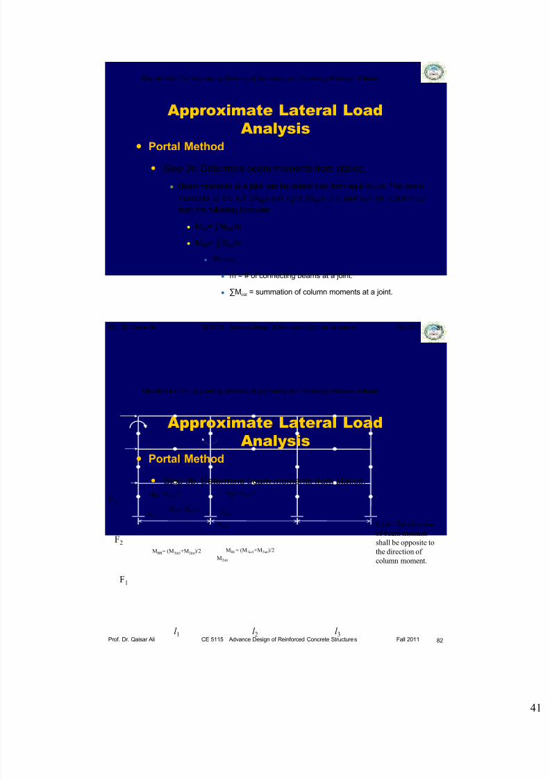
Step 3b: Determine beam moments from statics.
Beam moments at a joint can be determined from equilibrium. The beam
moments to the left (MBL) and right (MBR) of a joint can be determined
from the following formulae:
MBL= ∑Mcol/m
MBR= ∑Mcol/m
Where,
m = # of connecting beams at a joint.
∑Mcol = summation of column moments at a joint.
81
Department of Civil Engineering, University of Engineering and Technology Peshawar, Pakistan
Prof. Dr. Qaisar Ali CE 5115 Advance Design of Reinforced Concrete Structures Fall 2011
Approximate Lateral Load
Analysis Portal Method
Step 3b: Determine beam moments from statics.
82
F3
F2
F1
l 1 l 2 l 3
M3ext
M3int
M2int
Note: The direction
of beam moment
shall be opposite tothe direction of
column moment.
M3int
MBL= M3ext/1
MBR = M3int/2
MBL= M3int/2
MBR = (M3in3+M2int)/2 MBL= (M3in3+M2int)/2

7/27/2019 Lecture 14 Introduction to Earthquake Resistant Design of RC Structures (Part I)_2011.pdf
http://slidepdf.com/reader/full/lecture-14-introduction-to-earthquake-resistant-design-of-rc-structures-part 42/57
Department of Civil Engineering, University of Engineering and Technology Peshawar, Pakistan
Prof. Dr. Qaisar Ali CE 5115 Advance Design of Reinforced Concrete Structures Fall 2011
Approximate Lateral Load
Analysis Portal Method
Step 3c: Determine beam shear from statics.
As the point of inflection is assumed to lie at mid span, the beam shear
equals beam end moment divided by ½ beam span.
83
Department of Civil Engineering, University of Engineering and Technology Peshawar, Pakistan
Prof. Dr. Qaisar Ali CE 5115 Advance Design of Reinforced Concrete Structures Fall 2011
Approximate Lateral Load
Analysis Portal Method
Step 3c: Determine beam shear from statics.
84
F3
F2
F1
l 1 l 2 l 3
MBLMBR
PL=MBL/0.5l 1 PR =MBR /0.5l 1
MBLMBR
PL=MBL/0.5l 2 PR =MBR /0.5l 2 PL PR
PL PR
PL PR
PL PR
PL PR
PL PR
PL PR
7/27/2019 Lecture 14 Introduction to Earthquake Resistant Design of RC Structures (Part I)_2011.pdf
http://slidepdf.com/reader/full/lecture-14-introduction-to-earthquake-resistant-design-of-rc-structures-part 43/57
Department of Civil Engineering, University of Engineering and Technology Peshawar, Pakistan
Prof. Dr. Qaisar Ali CE 5115 Advance Design of Reinforced Concrete Structures Fall 2011
Approximate Lateral Load
Analysis Portal Method
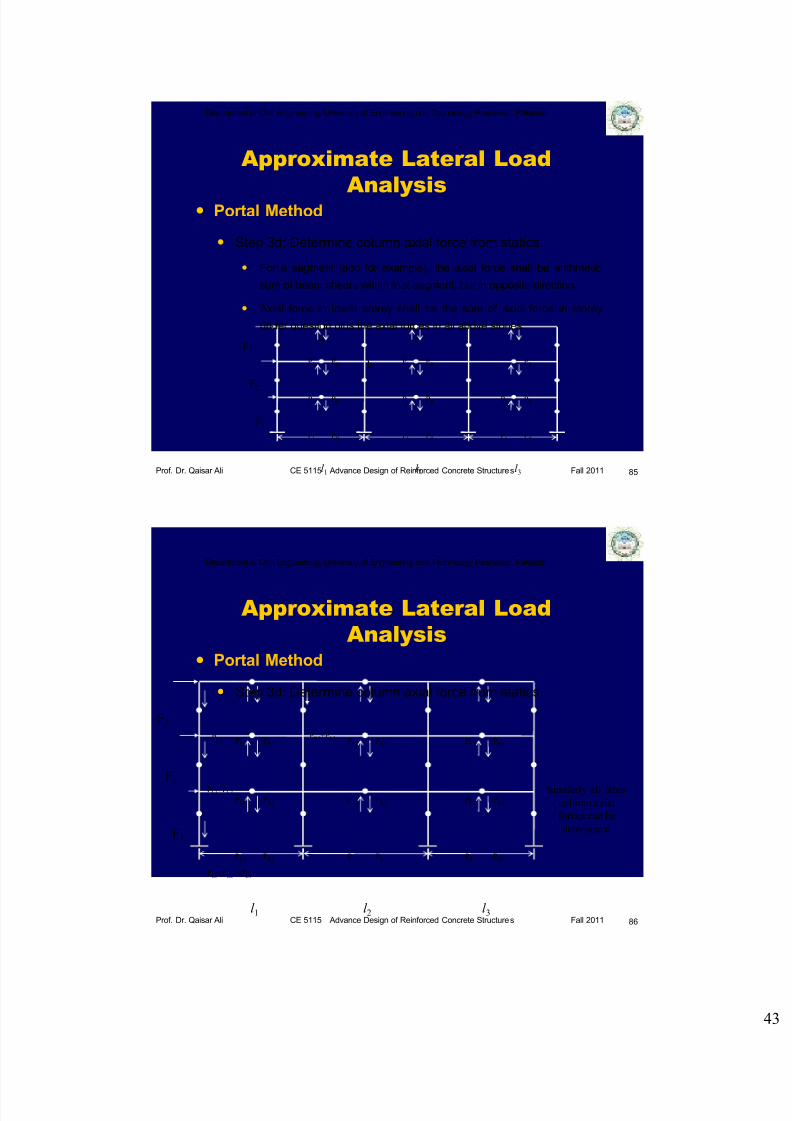
Step 3d: Determine column axial force from statics.
For a segment (abc for example), the axial force shall be arithmetic
sum of beam shears within that segment, but in opposite direction.
Axial force in lower storey shall be the sum of axial force in storey
under question plus the axial forces in all above stories.
85
F3
F2
F1
l 1 l 2 l 3
PL PR PL PR PR
PL PR PL PR PL PR
PL PR PL PR PL PR
a
b
c
Department of Civil Engineering, University of Engineering and Technology Peshawar, Pakistan
Prof. Dr. Qaisar Ali CE 5115 Advance Design of Reinforced Concrete Structures Fall 2011
Approximate Lateral Load
Analysis Portal Method
Step 3d: Determine column axial force from statics.
86
F3
F2
F1
l 1 l 2 l 3
PL3 PR3PL3 PR3 PR3
PL2 PR2PL2 PR2 PL2 PR2
PL1 PR1PL1 PR1 PL1 PR1
PL3 PL3
PL3+PL2
PR3+PL3
Similarly all other column axial
forces can be
determined
PL3+PL2 +PL1
7/27/2019 Lecture 14 Introduction to Earthquake Resistant Design of RC Structures (Part I)_2011.pdf
http://slidepdf.com/reader/full/lecture-14-introduction-to-earthquake-resistant-design-of-rc-structures-part 44/57
Department of Civil Engineering, University of Engineering and Technology Peshawar, Pakistan
Prof. Dr. Qaisar Ali CE 5115 Advance Design of Reinforced Concrete Structures Fall 2011
Approximate Lateral Load
Analysis Portal Method
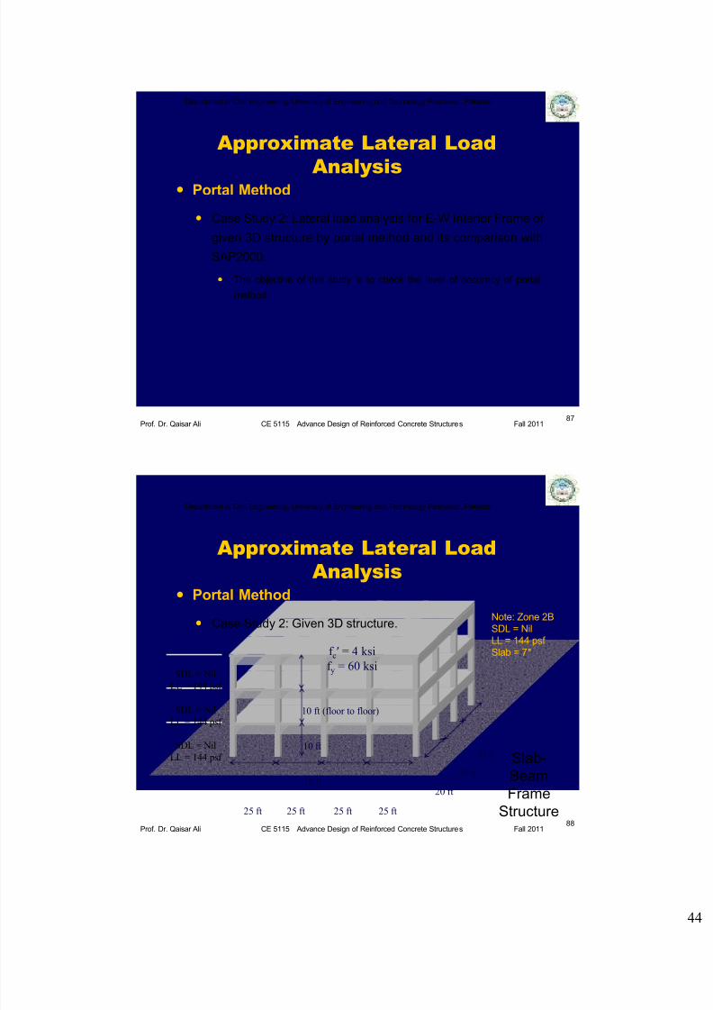
Case Study 2: Lateral load analysis for E-W Interior Frame of
given 3D structure by portal method and its comparison with
SAP2000.
The objective of this study is to check the level of accuracy of portal
method.
87
Department of Civil Engineering, University of Engineering and Technology Peshawar, Pakistan
Prof. Dr. Qaisar Ali CE 5115 Advance Design of Reinforced Concrete Structures Fall 2011
Approximate Lateral Load
Analysis Portal Method
Case Study 2: Given 3D structure.
88
25 ft 25 ft 25 ft 25 ft
20 ft
20 ft
20 ft
10 ft
10 ft
10 ft (floor to floor)
SDL = Nil
LL = 144 psf
SDL = NilLL = 144 psf
SDL = Nil
LL = 144 psf
f c′ = 4 ksi
f y = 60 ksi
Slab-
Beam
Frame
Structure
Note: Zone 2B
SDL = Nil
LL = 144 psf
Slab = 7″

7/27/2019 Lecture 14 Introduction to Earthquake Resistant Design of RC Structures (Part I)_2011.pdf
http://slidepdf.com/reader/full/lecture-14-introduction-to-earthquake-resistant-design-of-rc-structures-part 45/57
Department of Civil Engineering, University of Engineering and Technology Peshawar, Pakistan
Prof. Dr. Qaisar Ali CE 5115 Advance Design of Reinforced Concrete Structures Fall 2011
Approximate Lateral Load
Analysis Portal Method
Case Study 2: E-W Interior Frame
89
F3 =28.21 kip
l 1=25 ft l 2=25 ft l 3=25 ft
h=10 ft
F2 =18.61 kip
F1 =9.36 kip
h=10 ft
h=10 ft
l 4=25 ft
Department of Civil Engineering, University of Engineering and Technology Peshawar, Pakistan
Prof. Dr. Qaisar Ali CE 5115 Advance Design of Reinforced Concrete Structures Fall 2011
Approximate Lateral Load
Analysis Portal Method (Case Study 2)
Step 1: Locate points of inflection.
90
F3 =28.21 kip
l 1=25 ft l 2=25 ft l 3=25 ft l 4=25 ft
F2 =18.61 kip
F1 =9.36 kip
For
Hinge

7/27/2019 Lecture 14 Introduction to Earthquake Resistant Design of RC Structures (Part I)_2011.pdf
http://slidepdf.com/reader/full/lecture-14-introduction-to-earthquake-resistant-design-of-rc-structures-part 46/57
Department of Civil Engineering, University of Engineering and Technology Peshawar, Pakistan
Prof. Dr. Qaisar Ali CE 5115 Advance Design of Reinforced Concrete Structures Fall 2011
Approximate Lateral Load
Analysis Portal Method (Case Study 2)
Step 2: Determine column shear.
91
F3 =28.21 kip
l 1=25 ft l 2=25 ft l 3=25 ft l 4=25 ft
F2 =18.61 kip
F1 =9.36 kip
H3ext=F3/2n H3int=F3/n
n = 4
7.05 7.05 3.5
5.85
3.5 7.05
5.85 11.7 11.7 11.7
H2ext=(F3 + F2)/2n H2int=(F3 + F2)/n
H1int=(F3 + F2 + F1)/nH1ext=(F3 + F2 + F1)/2n
7.00 14.0 14.0 14.0 7.00
Department of Civil Engineering, University of Engineering and Technology Peshawar, Pakistan
Prof. Dr. Qaisar Ali CE 5115 Advance Design of Reinforced Concrete Structures Fall 2011
Approximate Lateral Load
Analysis Portal Method (Case Study 2)
Step 2: Determine column shear (comparison with SAP).
92l 1=25 ft l 2=25 ft l 3=25 ft l 4=25 ft
3.5
(4)
5.85
(7)
7.00
(11)
7.05
(7)
11.7
(13)
14.0
(13)
7.05
(7)
11.7
(12)
14.0
(13)
Portal Method
SAP 3D

7/27/2019 Lecture 14 Introduction to Earthquake Resistant Design of RC Structures (Part I)_2011.pdf
http://slidepdf.com/reader/full/lecture-14-introduction-to-earthquake-resistant-design-of-rc-structures-part 47/57
Department of Civil Engineering, University of Engineering and Technology Peshawar, Pakistan
Prof. Dr. Qaisar Ali CE 5115 Advance Design of Reinforced Concrete Structures Fall 2011
Approximate Lateral Load
Analysis Portal Method (Case Study 2)
Step 3a: Determine column moments.
93
F3 =
28.21 kip
l 1=25 ft l 2=25 ft l 3=25 ft l 4=25 ft
F2 =
18.61 kip
F1 =
9.36 kip
M = H ×h/2 (for all stories except bottom)
M = H × h (for bottom storey)
7.05 7.05 3.5
5.85
3.5 7.05
5.85 11.7 11.7 11.7
7.00 14.0 14.0 14.0 7.00
17.5
17.5
29.3
29.3
70 140
58.5
35.25
35.25
58.5
140
58.5
35.25
35.25
58.5
140
58.5
35.25
35.25
58.5
17.5
17.5
29.3
29.3
70
Department of Civil Engineering, University of Engineering and Technology Peshawar, Pakistan
Prof. Dr. Qaisar Ali CE 5115 Advance Design of Reinforced Concrete Structures Fall 2011
Approximate Lateral Load
Analysis Portal Method (Case Study 2)
Step 3a: Determine column moments (comparison with SAP).
94l 1=25 ft l 2=25 ft l 3=25 ft l 4=25 ft
17.5
(28)
17.5
(20)
35.25
(39)
35.25
(33)
35.25
(37)
35.25
(32)
29.3
(45)
29.3
(28)
58.5
(69)
58.5
(62)
58.5
(65)
58.5
(56)
70
(111)140
(133)
140
(129)
Portal Method
SAP 3D

7/27/2019 Lecture 14 Introduction to Earthquake Resistant Design of RC Structures (Part I)_2011.pdf
http://slidepdf.com/reader/full/lecture-14-introduction-to-earthquake-resistant-design-of-rc-structures-part 48/57
7/27/2019 Lecture 14 Introduction to Earthquake Resistant Design of RC Structures (Part I)_2011.pdf
http://slidepdf.com/reader/full/lecture-14-introduction-to-earthquake-resistant-design-of-rc-structures-part 49/57
Department of Civil Engineering, University of Engineering and Technology Peshawar, Pakistan
Prof. Dr. Qaisar Ali CE 5115 Advance Design of Reinforced Concrete Structures Fall 2011
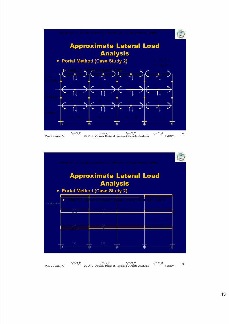
Approximate Lateral Load
Analysis Portal Method (Case Study 2)
Step 3c: Determine beam shear.
97
F3 =
28.21 kip
l 1=25 ft l 2=25 ft l 3=25 ft l 4=25 ft
F2 =
18.61 kip
F1 =
9.36 kip
PL= MBL/0.5l
PR = MBR /0.5l
17.5 17.5 17.5 17.5 17.5 17.5 17.5 17.5
46.8 46.8 46.8
46.8 46.8 46.8 46.8
46.8
99 99 99 99 99 99 99 99
1.4 1.4 1.4 1.4 1.4 1.4 1.4 1.4
3.74 3.74 3.74 3.74 3.74 3.74 3.74 3.74
7.92 7.92 7.92 7.92 7.92 7.92 7.92 7.92
Department of Civil Engineering, University of Engineering and Technology Peshawar, Pakistan
Prof. Dr. Qaisar Ali CE 5115 Advance Design of Reinforced Concrete Structures Fall 2011
Approximate Lateral Load
Analysis Portal Method (Case Study 2)
Step 3c: Determine beam shear (comparison with SAP).
98l 1=25 ft l 2=25 ft l 3=25 ft l 4=25 ft
1.4
(1.8)
1.4
(1.5)
3.74(4.4) 3.74(4)
7.92
(9)
7.92
(7)
Portal Method
SAP 3D

7/27/2019 Lecture 14 Introduction to Earthquake Resistant Design of RC Structures (Part I)_2011.pdf
http://slidepdf.com/reader/full/lecture-14-introduction-to-earthquake-resistant-design-of-rc-structures-part 50/57
Department of Civil Engineering, University of Engineering and Technology Peshawar, Pakistan
Prof. Dr. Qaisar Ali CE 5115 Advance Design of Reinforced Concrete Structures Fall 2011
Approximate Lateral Load
Analysis Portal Method (Case Study 2)
Step 3d: Determine column axial loads.
99
F3 =
28.21 kip
l 1=25 ft l 2=25 ft l 3=25 ft l 4=25 ft
F2 =
18.61 kip
F1 =
9.36 kip
1.4 1.4 1.4 1.4 1.4 1.4 1.4 1.4
3.74 3.74 3.74 3.74 3.74 3.74 3.74 3.74
7.92 7.92 7.92 7.92 7.92 7.92 7.92 7.92
1.4 0 0 0
0 0 0
0 0 0
5.14
13.06
1.4
5.14
13.06
Department of Civil Engineering, University of Engineering and Technology Peshawar, Pakistan
Prof. Dr. Qaisar Ali CE 5115 Advance Design of Reinforced Concrete Structures Fall 2011
Approximate Lateral Load
Analysis Portal Method (Case Study 2)
Step 3d: Determine column axial loads (comparison with SAP).
100l 1=25 ft l 2=25 ft l 3=25 ft l 4=25 ft
1.4
(2)
13.06
(17)
5.14
(7)
0
(-0.5)
0
(-1.4)
0
(-4.4)
0
(0)
0
(0)
0
(0)
Portal Method
SAP 3D
7/27/2019 Lecture 14 Introduction to Earthquake Resistant Design of RC Structures (Part I)_2011.pdf
http://slidepdf.com/reader/full/lecture-14-introduction-to-earthquake-resistant-design-of-rc-structures-part 51/57
Department of Civil Engineering, University of Engineering and Technology Peshawar, Pakistan
Prof. Dr. Qaisar Ali CE 5115 Advance Design of Reinforced Concrete Structures Fall 2011
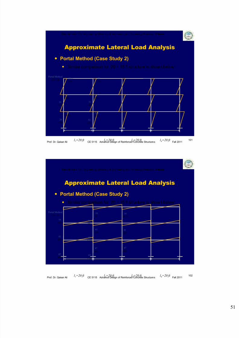
Approximate Lateral Load Analysis
101l 1=20 ft l 2=20 ft l 3=20 ft l 4=20 ft
16
(16)
16
(13)
31
(22)
31
(20)
26
(26)
26
(19)
52
(38)
52
(36)
61
(68)123
(77)
Portal Method
SAP 3D
Portal Method (Case Study 2) Similar comparison for 20 × 15 ft structure is shown below:
Department of Civil Engineering, University of Engineering and Technology Peshawar, Pakistan
Prof. Dr. Qaisar Ali CE 5115 Advance Design of Reinforced Concrete Structures Fall 2011
Approximate Lateral Load Analysis
102l 1=20 ft l 2=20 ft l 3=20 ft l 4=20 ft
16
(12)
16
(9)16
(8.5)
16
(8)
41(29)
41
(25)41
(22)
41(22)
87
(64)
87
(50)
87
(43)
87
(40)
Portal Method
SAP 3D
Portal Method (Case Study 2)
Similar comparison for 20 × 15 ft structure is shown below:

7/27/2019 Lecture 14 Introduction to Earthquake Resistant Design of RC Structures (Part I)_2011.pdf
http://slidepdf.com/reader/full/lecture-14-introduction-to-earthquake-resistant-design-of-rc-structures-part 52/57
Department of Civil Engineering, University of Engineering and Technology Peshawar, Pakistan
Prof. Dr. Qaisar Ali CE 5115 Advance Design of Reinforced Concrete Structures Fall 2011
Approximate Lateral Load
Analysis Portal Method
Case Study 3: Lateral Load Analysis of a frame
corresponding to seismic demand in seismic zones 1 to 4
using Portal Method.
103
Department of Civil Engineering, University of Engineering and Technology Peshawar, Pakistan
Prof. Dr. Qaisar Ali CE 5115 Advance Design of Reinforced Concrete Structures Fall 2011
Approximate Lateral Load
Analysis Portal Method
Case Study 3
104
20 ft 20 ft 20 ft 20 ft
15 ft
15 ft
15 ft
10.5 ft
10.5 ft
10.5 ft (floor to floor)
SDL = 40 psf
LL = 60 psf
SDL = 40 psf LL = 60 psf
SDL = 40 psf
LL = 60 psf
f c′ = 3 ksi
f y = 40 ksi
Slab-
Beam
Frame
Structure

7/27/2019 Lecture 14 Introduction to Earthquake Resistant Design of RC Structures (Part I)_2011.pdf
http://slidepdf.com/reader/full/lecture-14-introduction-to-earthquake-resistant-design-of-rc-structures-part 53/57
Department of Civil Engineering, University of Engineering and Technology Peshawar, Pakistan
Prof. Dr. Qaisar Ali CE 5115 Advance Design of Reinforced Concrete Structures Fall 2011
Approximate Lateral Load
Analysis Portal Method
Case Study 3: Zone 1 (Bending moments)
105
Ca = 0.12
Cv = 0.18
R = 8.5
V = 20.04 kips
Department of Civil Engineering, University of Engineering and Technology Peshawar, Pakistan
Prof. Dr. Qaisar Ali CE 5115 Advance Design of Reinforced Concrete Structures Fall 2011
Approximate Lateral Load
Analysis Portal Method
Case Study 3: Zone 2A (Bending moments)
106
Ca = 0.22
Cv = 0.32
R = 8.5
V = 36.74 kips
7/27/2019 Lecture 14 Introduction to Earthquake Resistant Design of RC Structures (Part I)_2011.pdf
http://slidepdf.com/reader/full/lecture-14-introduction-to-earthquake-resistant-design-of-rc-structures-part 54/57
Department of Civil Engineering, University of Engineering and Technology Peshawar, Pakistan
Prof. Dr. Qaisar Ali CE 5115 Advance Design of Reinforced Concrete Structures Fall 2011
Approximate Lateral Load
Analysis Portal Method
Case Study 3: Zone 2B (Bending moments)
107
Ca = 0.28
Cv = 0.40
R = 8.5
V = 46.76 kips
Department of Civil Engineering, University of Engineering and Technology Peshawar, Pakistan
Prof. Dr. Qaisar Ali CE 5115 Advance Design of Reinforced Concrete Structures Fall 2011
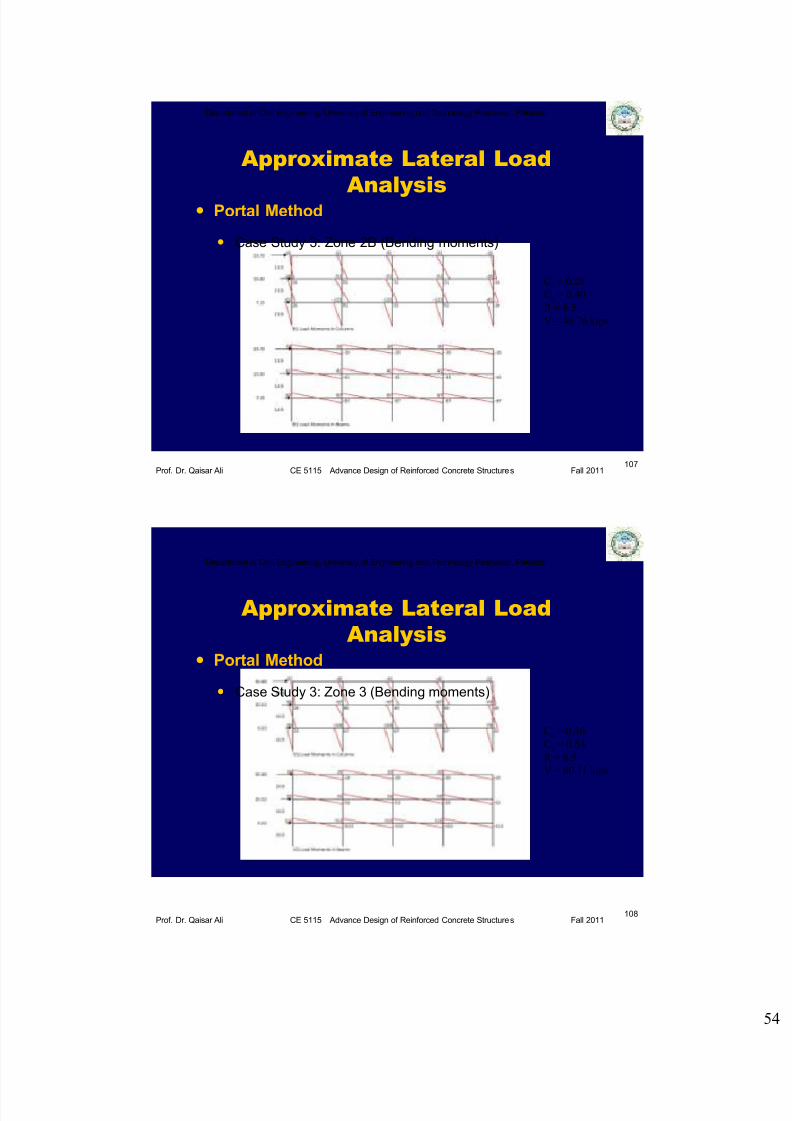
Approximate Lateral Load
Analysis Portal Method
Case Study 3: Zone 3 (Bending moments)
108
Ca = 0.36
Cv = 0.54
R = 8.5
V = 60.11 kips
7/27/2019 Lecture 14 Introduction to Earthquake Resistant Design of RC Structures (Part I)_2011.pdf
http://slidepdf.com/reader/full/lecture-14-introduction-to-earthquake-resistant-design-of-rc-structures-part 55/57
Department of Civil Engineering, University of Engineering and Technology Peshawar, Pakistan
Prof. Dr. Qaisar Ali CE 5115 Advance Design of Reinforced Concrete Structures Fall 2011
Approximate Lateral Load
Analysis Portal Method
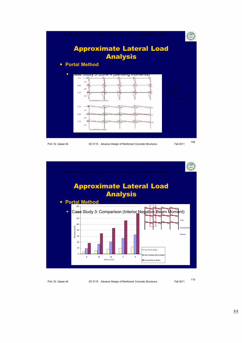
Case Study 3: Zone 4 (Bending moments)
109
Ca = 0.44
Cv = 0.64
R = 8.5
V = 73.47 kips
Department of Civil Engineering, University of Engineering and Technology Peshawar, Pakistan
Prof. Dr. Qaisar Ali CE 5115 Advance Design of Reinforced Concrete Structures Fall 2011
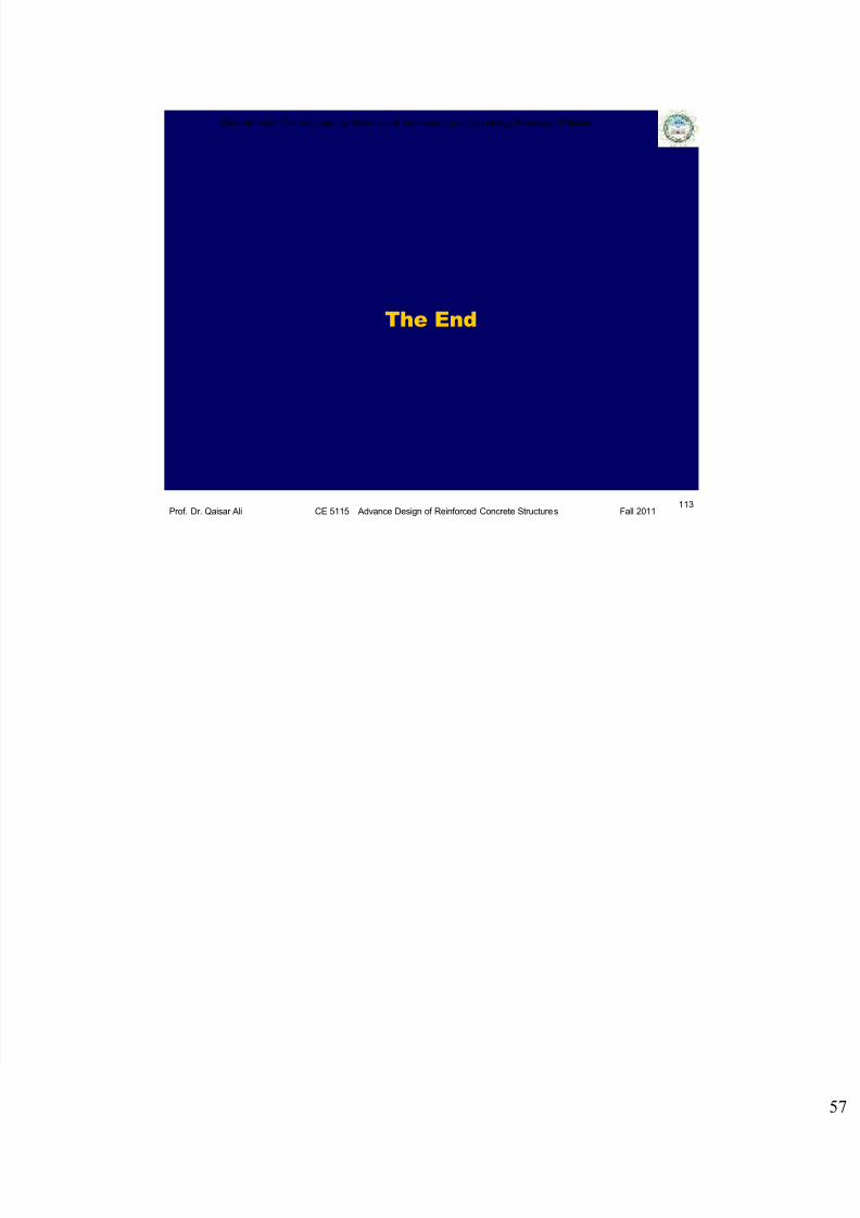
Approximate Lateral Load
Analysis Portal Method
Case Study 3: Comparison (Interior Negative Beam Moment)
110
Top
Intermediate
Bottom

7/27/2019 Lecture 14 Introduction to Earthquake Resistant Design of RC Structures (Part I)_2011.pdf
http://slidepdf.com/reader/full/lecture-14-introduction-to-earthquake-resistant-design-of-rc-structures-part 56/57
Department of Civil Engineering, University of Engineering and Technology Peshawar, Pakistan
Prof. Dr. Qaisar Ali CE 5115 Advance Design of Reinforced Concrete Structures Fall 2011
Approximate Lateral Load
Analysis Portal Method
Case Study 3: Comparison (Column Moment)
111
Top
Intermediate
Bottom
Department of Civil Engineering, University of Engineering and Technology Peshawar, Pakistan
Prof. Dr. Qaisar Ali CE 5115 Advance Design of Reinforced Concrete Structures Fall 2011
References
ACI 318
UBC-97
BCP SP-2007
Earthquake tips from IITK.
112
Intermediate
Bottom
7/27/2019 Lecture 14 Introduction to Earthquake Resistant Design of RC Structures (Part I)_2011.pdf
http://slidepdf.com/reader/full/lecture-14-introduction-to-earthquake-resistant-design-of-rc-structures-part 57/57
Department of Civil Engineering, University of Engineering and Technology Peshawar, Pakistan
Prof. Dr. Qaisar Ali CE 5115 Advance Design of Reinforced Concrete Structures Fall 2011
The End
113


