Perle 594Reference Guide
00

teredspective
Copyright and trademarks
Copyright 1999. All rights reserved, Perle Systems Limited. Perle, the Perle logo, PerleTALK for DOS, PerleTALK for Windows, and the Perle 594 are registrademarks of Perle Systems. All other trademarks appearing in this manual are trademarks of their recompanies.

Table of Contents
List of Figures v
How To Use This Guide vii
Conventions used in this guide ..................................................................................................... vii
Chapter 1: AS/400 Configuration Examples 1
SDLC Leased ........................................................................................................................... 2X.21 Switched .......................................................................................................................... 3X.25 Switched .......................................................................................................................... 4X.25 Permanent ....................................................................................................................... 5AS/400 Token-Ring Attachment ............................................................................................. 6AS/400 Ethernet Attachment ................................................................................................... 7SDLC Leased through SNA SubArea Network ...................................................................... 8SDLC Leased through APPN Network ................................................................................... 9AS/400 Frame Relay Attachment and FR-TR Bridge .......................................................... 10AS/400 Frame Relay Attachment and IP Routing (with 594 IP Routing Feature only) ....... 11AS/400 TCP/IP Token Ring Attachment .............................................................................. 12AS/400 TCP/IP Ethernet Attachment and Twinax IP Routing (with 594 IP Routing feature only) ................................................................................... 13AS/400 TCP/IP Frame Relay Attachment ............................................................................. 14
Chapter 2: Understanding Configuration Parameters 15
Chapter 3: Message Codes and SRCs 37
Message Codes ............................................................................................................................. 37System Reference Codes .............................................................................................................. 39
594 System Hardware and Configuration SRC’s (100-199) ................................................. 39NWS Operational SRC’s (0000-0177) .................................................................................. 41X.25 Communication SRC’s (100000-1BFF00) ................................................................... 45X.21 Switched Communication SRCs (200000-250300) ...................................................... 54Vi25 bis SRC’s (300000-323400) ......................................................................................... 58SNA Communication SRC’s (400000-470200) .................................................................... 59594 System Operations SRC’s (500000-520003) .................................................................. 64LAN SRC’s (540000-540425) ............................................................................................... 65Frame Relay Communication SRCs (560000-560410) ......................................................... 68Frame Relay Token-Ring Bridge SRC's(570000-57FFFF) ................................................... 69TCP/IP Error SRCs(5A000-5AFFFF) ................................................................................... 72Frame Relay IP Routing SRCs(5B000-5BFFFF) .................................................................. 73
Hardware Error SRCs(E00XXX) ................................................................................................. 75Software Error SRCs(FXXXX) ....................................................................................................75Utility Program Messages and SRCs ............................................................................................ 76
594 Utility Program Installation Codes ................................................................................. 76594 Utility Program Run Time Messages ............................................................................. 76
Perle 594 Reference Guide iii

Chapter 4: Specifying Ethernet Address Formats 85
Using Ethernet address format ...................................................................................................... 85Using Token-Ring address format ................................................................................................ 85
Converting Token-Ring address formats ............................................................................... 85
Chapter 5: TCP/IP White Paper 87
95-2435-02 ............................................................................................................................. 89
Glossary 107
iv Perle 594 Reference Guide

List of Figures
Fig. 1: SDLC Leased configuration . . . . . . . . . . . . . . . . . . . . . . . . . . . . . . . . . . . . . . 2 Fig. 2: SDLC Leased configuration cross-reference . . . . . . . . . . . . . . . . . . . . . . . . . 2 Fig. 3: X.21 Switched configuration . . . . . . . . . . . . . . . . . . . . . . . . . . . . . . . . . . . . . 3 Fig. 4: X.21 Switched configuration cross-reference . . . . . . . . . . . . . . . . . . . . . . . . 3 Fig. 5: X.25 Switched configuration . . . . . . . . . . . . . . . . . . . . . . . . . . . . . . . . . . . . . 4 Fig. 6: X.25 Switched configuration cross-reference . . . . . . . . . . . . . . . . . . . . . . . . 4 Fig. 7: X.25 Permanent configuration . . . . . . . . . . . . . . . . . . . . . . . . . . . . . . . . . . . . 5 Fig. 8: X.25 Permanent configuration cross-reference . . . . . . . . . . . . . . . . . . . . . . . 5 Fig. 9: AS/400 Token-Ring configuration . . . . . . . . . . . . . . . . . . . . . . . . . . . . . . . . . 6 Fig. 10: AS/400 Token-Ring configuration cross-reference . . . . . . . . . . . . . . . . . . . 6 Fig. 11: AS/400 Ethernet configuration . . . . . . . . . . . . . . . . . . . . . . . . . . . . . . . . . . 7 Fig. 12: AS/400 Ethernet configuration cross-reference . . . . . . . . . . . . . . . . . . . . . . 7 Fig. 13: SNA SubArea Network configuration . . . . . . . . . . . . . . . . . . . . . . . . . . . . . 8 Fig. 14: SNA SubArea Network configuration cross-reference . . . . . . . . . . . . . . . . 8 Fig. 15: APPN Network configuration . . . . . . . . . . . . . . . . . . . . . . . . . . . . . . . . . . . 9 Fig. 16: APPN configuration cross-reference . . . . . . . . . . . . . . . . . . . . . . . . . . . . . . 9 Fig. 17: AS/400 Frame Relay and IP Routing configuration . . . . . . . . . . . . . . . . . 10 Fig. 18: AS/400 Frame Relay Configuration cross reference . . . . . . . . . . . . . . . . . 10 Fig. 19: AS/400 Frame Relay and IP Routing configuration . . . . . . . . . . . . . . . . . 11 Fig. 20: AS/400 Frame Relay and IP Routing Config. cross reference . . . . . . . . . 11 Fig. 21: AS/400 TCP/IP Token-Ring configuration . . . . . . . . . . . . . . . . . . . . . . . . 12 Fig. 22: AS/400 TCP/IP Token-Ring config. cross-reference . . . . . . . . . . . . . . . . . 12 Fig. 23: AS/400 TCP/IP Ethernet configuration . . . . . . . . . . . . . . . . . . . . . . . . . . . 13 Fig. 24: AS/400 TCP/IP Ethernet and Twinax IP Routing config. cross-reference 13 Fig. 25: AS/400 TCP/IP Frame Relay configuration . . . . . . . . . . . . . . . . . . . . . . . 14 Fig. 26: AS/400 TCP/IP Frame Relay config. cross-reference . . . . . . . . . . . . . . . . 14
Perle 594 Reference Guide v

vi Perle 594 Reference Guide

ofanual.d.
key
shown
How To Use This Guide
The Perle 594 Reference Guide provides a set of reference material for the 594 family controllers. Some models of the 594 may not support all features described in this mPlease refer to the appropiate User’s Guide for details on the features that are supporte
Conventions used in this guide Information that you enter by typing on a workstation keyboard, or on the Perle 594Mpanel, is shown in bold Courier typeface characters.
Buttons that you press on a workstation keyboard, or on the Perle 594M key panel, are in bold characters.
All titles are shown in italic characters; titles include: book titles, chapter titles, and sectiontitles.
ConfigurationExamples
Read Chapter 1: Configuring the AS/400 for common examples on how to configure the AS/400.
ConfigurationParameters
Read Chapter 2: Understanding Configuration Parameters for an alphabetical list of parameters that require configuration on the AS/400.
Problems Read Chapter 3: Message Codes and SRC’s for a list of the error codes that can be displayedon front panels or recorded in error logs.
EthernetAddress Formats
Read Chapter 4: Specifying Ethernet Address Formats for information on Ethernet addressing formats.
594 and AS/400TCP/IP
Configuration
Read Chapter 5: TCP/IP White Paper for information on configuration of TCP/IP controllers
Perle 594 Reference Guide vii

Conventions used in this guide
viii Perle 594 Reference Guide

only)
he Perlee found
/400
Chapter 1: AS/400 Configuration Examples
This chapter provides configuration examples for the following connections:
• SDLC Leased
• X.21 Switched
• X.25 Switched
• X.25 Permanent
• AS/400 Token-Ring Attachment
• AS/400 Ethernet Attachment
• SDLC Leased through SNA SubArea Network
• SDLC Leased through APPN Network
• AS/400 Frame Relay Attachment and FR-TR Bridge
• AS/400 Frame Relay Attachment and IP Routing (with 594 IP Routing Feature only)
• AS/400 TCP/IP Token-Ring Attachment
• AS/400 TCP/IP Ethernet Attachment and Twinax IP Routing (with 594 IP Routing Feature
• AS/400 TCP/IP Frame Relay Attachment
These examples demonstrate how configuration parameters on the AS/400 relate to those on t594. These parameters are listed under the title of the configuration screen on which they can b(on the AS/400 or the Perle 594).
Refer to Chapter 2 for more information on Perle 594 parameters, or to the appropriate ASdocumentation on AS/400 parameters.
Perle 594 Reference Guide 1

Chapter 1: AS/400 Configuration Examples
SDLC Leased
Fig. 1: SDLC Leased configuration
Fig. 2: SDLC Leased configuration cross-reference
NWSRWSPRT26
594 AS/400RCHAS149
NWSRWSDSP00
Twinaxial
Network ID = ITSCNET
SDLCleased line
Perle 594
ITSCNETRCH594RCH594QRMTWSCRCHAS149ITSCNET
H1 : 31213
H1 : 4H1 : 1H1 : 2
NWS Config Screen 2
001
AA =2 =
NWS Config Screen 1
594 network name594 LU name594 CP nameMode nameAS/400 LU nameAS/400 network name
Network Information
SDLC594 station address
AS/400 Connection
3 = 0 1 1 0 0 0 0 Communication parametersNRZIPoint-to-pointFull duplexLeased line
AS/400
CTLDTYPELINKTYPERMTLOCNAMELCLLOCNAMERMTNETID
RWS5945494*NONERCH594*NETATR*NETATR
RWS Controller Description
DEVDCTLLOCADR
RWSDSP00RWS59400 * * RWSDSP00
0 Port0 Address
NWS Display Device Description
** RWSPRT262 Port6 Address
DEVDCTLLOCADR
RWSPRT26RWS59414 **
NWS Printer Device Description
CTLDLINKTYPELINERMTNETIDRMTCPNAMESTNADR
APPC Controller DescriptionRCH594EPP*SDLCITSCSDLCPP*NETATRRCH59401
LCLLOCNAMELCLNETID
RCHAS149ITSCNET
CRTLINSDLCLINDCNNDUPLEXNRZI
ITSCSDLCPP*NONSWTPP*FULL*YES
Network Attributes
Line Description
2 Perle 594 Reference Guide

Chapter 1: AS/400 Configuration Examples
X.21 Switched
Fig. 3: X.21 Switched configuration
Fig. 4: X.21 Switched configuration cross-reference
NWSRWSPRT26
594 AS/400RCHAS149
NWSRWSDSP00
Twinaxial
Network ID = ITSCNET
X.21switched
Perle 594
NWS Config Screen 2594 LU name594 CP nameMode name594 connection numberAS/400 LU nameAS/400 network name594 network nameAS/400 connection number
RCH594RCH594QRMTWSC222222RCHAS149ITSCNETITSCNET111111
1213
H1 : 415
H1 : 1H1 : 2H1 : 3H1 : 5
Network Information
5010
AA =2 =D =
NWS Config Screen 1X.21594 station addressSHM dial digit format
AS/400 Connection
AS/400
CTLDTYPELINKTYPERMTLOCNAMELCLLOCNAMERMTNETID
RWS5945494*NONERCH594*NETATR*NETATR
RWS Controller Description
DEVDCTLLOCADR
RWSDSP00RWS59400 * * RWSDSP00
0 Port0 Address
NWS Display Device Description
** RWSPRT262 Port6 Address
DEVDCTLLOCADR
RWSPRT26RWS59414 **
NWS Printer Device Description
RCH594X21*NETATRRCH59422222201
LCLLOCNAMELCLNETID
RCHAS149ITSCNET
Network Attributes
CRTLINSDLCSHMCALLFMTCALLNBR
DNIC111111
Line Description
CTLDRMTNETIDRMTCPNAMECNNNBRSTNADR
APPC Controller Description
Perle 594 Reference Guide 3
Chapter 1: AS/400 Configuration Examples
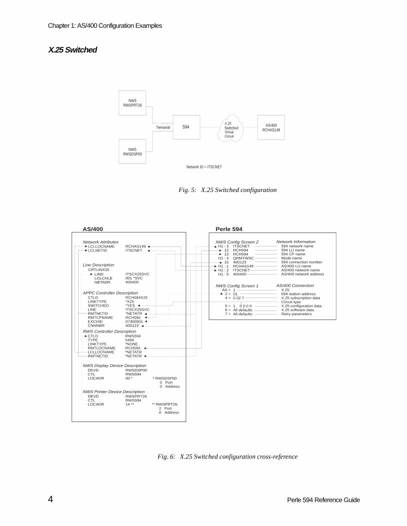
X.25 Switched
Fig. 5: X.25 Switched configuration
Fig. 6: X.25 Switched configuration cross-reference
AS/400RCHAS149
NWSRWSPRT26
494E
NWSRWSDSP00
Twinaxial
Network ID = ITSCNET
X.25PermanentVirtualCircuit
594 Switched
Perle 594
NWS Config Screen 2594 network name594 LU name594 CP nameMode name594 connection numberAS/400 LU nameAS/400 network nameAS/400 network address
ITSCNETRCH594RCH594QRMTWSC400123RCHAS149ITSCNET400400
H1 : 31213
H1 : 415
H1 : 1H1 : 2H1 : 5
Network Information
1010 02 7
1 0 0 0 0All defaultsAll defaults
AA =2 =4 =
5 =6 =7 =
NWS Config Screen 1X.25594 station addressX.25 subscription dataCircuit typeX.25 configuration dataX.25 software dataRetry parameters
AS/400 Connection
AS/400
CTLDTYPELINKTYPERMTLOCNAMELCLLOCNAMERMTNETID
RWS5945494*NONERCH594*NETATR*NETATR
RWS Controller Description
DEVDCTLLOCADR
RWSDSP00RWS59400 * * RWSDSP00
0 Port0 Address
NWS Display Device Description
** RWSPRT262 Port6 Address
DEVDCTLLOCADR
RWSPRT26RWS59414 **
NWS Printer Device Description
RCH594X25*X25*YESITSCX25SVC*NETATRRCH59407300001400123
LCLLOCNAMELCLNETID
RCHAS149ITSCNET
Network Attributes
CRTLINX25LINDLGLCHLENETADR
ITSCX25SVC001 *SVC400400
Line Description
CTLDLINKTYPESWITCHEDLINERMTNETIDRMTCPNAMEEXCHIDCNNNBR
APPC Controller Description
4 Perle 594 Reference Guide

Chapter 1: AS/400 Configuration Examples
X.25 Permanent
Fig. 7: X.25 Permanent configuration
Fig. 8: X.25 Permanent configuration cross-reference
AS/400RCHAS149
NWSRWSPRT26
494E
NWSRWSDSP00
Twinaxial
Network ID = ITSCNET
X.25PermanentVirtualCircuit
594
Perle 494E
NWS Config Screen 2494E network name494E LU name494E CP nameMode nameAS/400 LU nameAS/400 network nameAS/400 logical channel
ITSCNETRCH494ERCH494EQRMTWSCRCHAS149ITSCNET001
H1 : 31213
H1 : 4H1 : 1H1 : 2H1 : 6
Network Information
1010 02 7
1 1 0 0 0All defaultsAll defaults
AA =2 =4 =
5 =6 =7 =
NWS Config Screen 1X.25494E station addressX.25 subscription dataCircuit typeX.25 configuration dataX.25 software dataRetry parameters
AS/400
CTLDTYPELINKTYPERMTLOCNAMELCLLOCNAMERMTNETID
RWS494E5494*NONERCH594*NETATR*NETATR
RWS Controller Description
DEVDCTLLOCADR
RWSDSP00RWS494E00 * * RWSDSP00
0 Port0 Address
NWS Display Device Description
** RWSPRT262 Port6 Address
DEVDCTLLOCADR
RWSPRT26RWS494E14 **
NWS Printer Device Description
RCH494EX25*X25*NOITSCX25PVC*NETATRRCH494E07300001001
LCLLOCNAMELCLNETID
RCHAS149ITSCNET
Network Attributes
CRTLINX25LINDLGLCHLE
ITSCX25PVC001 *PVC
Line Description
CTLDLINKTYPESWITCHEDLINERMTNETIDRMTCPNAMEEXCHIDLGLCHID
APPC Controller DescriptionRCH594X25
RWS594
RWS594
RWS594
RCH594
594 network name594 LU name594 CP nameRCH594
594
RCH594
594
Perle 594 Reference Guide 5

Chapter 1: AS/400 Configuration Examples
AS/400 Token-Ring Attachment
Fig. 9: AS/400 Token-Ring configuration
Fig. 10: AS/400 Token-Ring configuration cross-reference
NWSRWSPRT26
594 AS/400RCHAS149
NWSRWSDSP00
Twinaxial
Network ID = ITSCNET
Token-Ring
Perle 594
NWS Config Screen 2594 network name594 LU name594 CP nameMode name594 Token-Ring addressAS/400 LU nameAS/400 network nameAS/400 Token-Ring addressAS/400 Token-Ring SAP
ITSCNETRCH594RCH594QRMTWSC400005940003RCHAS149ITSCNET40000000014904
H1 : 31213
H1 : 415
H1 : 1H1 : 2H1 : 5H1 : 7
Network Information
404
AA =F =
NWS Config Screen 1Token-Ring594 SAP
AS/400 Connection
AS/400
CTLDTYPELINKTYPERMTLOCNAMELCLLOCNAMERMTNETID
RWS5945494*NONERCH594*NETATR*NETATR
RWS Controller Description
DEVDCTLLOCADR
RWSDSP00RWS59400 * * RWSDSP00
0 Port0 Address
NWS Display Device Description
** RWSPRT262 Port6 Address
DEVDCTLLOCADR
RWSPRT26RWS59414 **
NWS Printer Device Description
LINKTYPELINERMTNETIDRMTCPNAMEADPTADRDSAPSSAP
APPC Controller Description*LANITSCTRN*NETATRRCH594400059400030404
LCLLOCNAMELCLNETID
RCHAS149ITSCNET
CRTLINTRNLINDADPTADRAUTOCRTCTL
ITSCTRN400000000149*YES
Network Attributes
Line Description
Auto-created
6 Perle 594 Reference Guide

Chapter 1: AS/400 Configuration Examples
AS/400 Ethernet Attachment
Fig. 11: AS/400 Ethernet configuration
Fig. 12: AS/400 Ethernet configuration cross-reference
NWSRWSPRT26
594 AS/400RCHAS149
NWSRWSDSP00
Twinaxial
Network ID = ITSCNET
Ethernet
Perle 594
NWS Config Screen 2594 network name594 LU name594 CP nameMode name594 Ethernet addressAS/400 LU nameAS/400 network nameAS/400 Ethernet addressAS/400 SAP
ITSCNETRCH594RCH594QRMTWSC02005940004RCHAS149ITSCNET02000000000104
H1 : 31213
H1 : 415
H1 : 1H1 : 2H1 : 5H1 : 7
Network Information
AS/400
CTLDTYPELINKTYPERMTLOCNAMELCLLOCNAMERMTNETID
RWS5945494*NONERCH594*NETATR*NETATR
RWS Controller Description
DEVDCTLLOCADR
RWSDSP00RWS59400 * * RWSDSP00
0 Port0 Address
NWS Display Device Description
** RWSPRT262 Port6 Address
DEVDCTLLOCADR
RWSPRT26RWS59414 **
NWS Printer Device Description
LINKTYPELINERMTNETIDRMTCPNAMEADPTADRDSAPSSAP
APPC Controller Description*LANITSCTRN*NETATRRCH594020059400040404
LCLLOCNAMELCLNETID
RCHAS149ITSCNET
CRTLINETHLINDADPTADRAUTOCRTCTL
ITSCETH020000000001*YES
Network Attributes
Line Description
Auto-created 504
AA =NWS Config Screen 1
Ethernet594 SAP
AS/400 Connection
Perle 594 Reference Guide 7

Chapter 1: AS/400 Configuration Examples
SDLC Leased through SNA SubArea Network
Fig. 13: SNA SubArea Network configuration
Fig. 14: SNA SubArea Network configuration cross-reference
NWSRWSPRT26
594
AS/400RCHAS149
NWSRWSDSP00
Twinaxial
Network ID = ITSCNET
NCP
IBM 3745
HOST
IBM 370VTAM
SDLCleased line
SDLCleased line
Perle 594NWS Config Screen 2
NWS Config Screen 1
LU594RCH594QRMTWSCRCHAS149ITSCNETNET594
1213
H1 : 4H1 : 1H1 : 2H1 : 3
3 = 0 1 1 0 0 0 0
594 LU name594 CP nameMode nameAS/400 LU nameAS/400 network name594 network name
Network Information
002
AA =2 =
SDLC594 station address
AS/400 Connection
Communication parametersData encodingPoint-to-pointFull duplexLeased line
Host
NETID =SSCPNAME =
XNETALS =
VTAM STARTUPITSCNETMVS1YES
QRMTWSCVTAM MODTAB Entry
NCPLine to 594
RCH594 PU ADDR =PUTYPE =
XID =LU594 LU LOCADDR =
02
2YES0
Line to AS/400RCHAS149 PU ADDR =
PUTYPE =XID =
RCHAS149 LU LOCADDR =
012YES0
AS/400
CTLDTYPELINKTYPERMTLOCNAMELCLLOCNAMERMTNETID
RWS5945494*NONELU594RCHAS149*NET594
RWS Controller Description
CTLDLINKTYPELINERMTNETIDRMTCPNAMESTNADR
Host or APPC Controller DescriptionRCH594PP*SDLCITSCSDLCPP*NETATRMVS101
CRTLINSDLCLINDCNNDUPLEXNRZI
ITSCSDLCPP*NONSWTPP*FULL*YES
LCLLOCNAMELCLNETID
RCHAS149ITSCNET
Network Attributes
Line Description
DEVDCTLLOCADR
RWSDSP00RWS59400 *
* RWSDSP000 Port0 Address
NWS Display Device Description
** RWSPRT262 Port6 Address
DEVDCTLLOCADR
RWSPRT26RWS59414 **
NWS Printer Device Description
RMTLOCNAMELU594
RMTNETIDNET594
LCLLOCNAMERCHAS149
RMTCPNAMEMVS1
CPNETIDITSCNET
Remote Location List
8 Perle 594 Reference Guide

Chapter 1: AS/400 Configuration Examples
SDLC Leased through APPN Network
Fig. 15: APPN Network configuration
Fig. 16: APPN configuration cross-reference
NWSRWSPRT26
NWSRWSDSP00
Twinaxial 594 AS/400RCHAS149
CommunicationNetwork
AS/400RCHAS040
SDLC
Perle 594
NWS Config Screen 1001
AA =2 =
SDLC594 station address
AS/400 Connection
NWS Config Screen 2RCH594RCH594QRMTWSCRCHAS149ITSCNETITSCNET
1213
H1 : 4H1 : 1H1 : 2H1 : 3
594 LU name594 CP nameMode nameAS/400 LU nameAS/400 network name594 Network name
Network Information
3 = 0 1 1 0 0 0 0 Communication parametersData encodingPoint-to-pointFull duplexLeased line
Adjacent AS/400
LCLNETIDLCLCPNAMELCLLOCNAMENODETYPE
ITSCNETAPPN1RCHAS040*NETNODE
Network Attributes
CTLDLINKTYPELINERMTNETIDRMTCPNAMESTNADRNODETYPE
APPC Controller DescriptionC594APPN01*SDLCLINXX011*NETATRRCH59401*LENNODE
CTLDLINKTYPELINERMTNETIDRMTCPNAMESTNADRNODETYPE
APPC Controller Description
CRTLINSDLCLINDCNNDUPLEXLINE SPEEDNRZIROLETEXT - LINE TO 594
LINXX011*NONSWTPP*FULL56000*YES*PRI
Line Description
LINDCNNDUPLEXLINESPEEDNRZIROLETEXT - Line to Non-Adjacent AS/400
Line DescriptionLINXX061*NONSWTPP*FULL56000*YES*SEC
CTLDLINKTYPELINERMTCPNAMESTNADRNODETYPE
APPC Controller DescriptionC594APPN02*SDLCLINXX061APPN201*ENDNODE
Remote Location List for RCHAS040
RMTLOCNAMERCHAS149
RMTNETIDITSCNET
LCLLOCNAMERCHAS040
RMTCPNAMEAPPN2
CPNETIDITSCNET
CTLDTYPELINKTYPERMTLOCNAMELCLLOCNAMERMTNETID
RWS5945494*NONERCH594*NETATR*NETATR
RWS Controller Description
DEVDCTLLOCADR
RWSDSP00RWS59400 *
* RWSDSP000 Port0 Address
NWS Display Device Description
** RWSPRT262 Port6 Address
DEVDCTLLOCADR
RWSPRT26RWS59414 **
NWS Printer Device Description
Non-Adjacent AS/400
LCLNETIDLCLCPNAMELCLLOCNAMENODETYPE
ITSCNETAPPN2RCHAS149*ENDNODE
Network Attributes
LINDCNNDUPLEXLINESPEEDNRZIROLETEXT - Line to Adjacent AS/400 (RCHAS040)
Line DescriptionLINXX071*NONSWTPP*FULL56000*YES*PRI
CTLDLINKTYPELINERMTCPNAMESTNADRNODETYPE
APPC Controller DescriptionC494APPN03*SDLCLINXX071APPN101*NETNODE
Remote Location List for RCHAS149
RMTLOCNAMERCHAS040
RMTNETIDITSCNET
LCLLOCNAMERCHAS149
RMTCPNAMEAPPN1
CPNETIDITSCNET
Perle 594 Reference Guide 9

Chapter 1: AS/400 Configuration Examples
AS/400 Frame Relay Attachment and FR-TR Bridge
Fig. 17: AS/400 Frame Relay and IP Routing configuration
Fig. 18: AS/400 Frame Relay Configuration cross reference
Twinaxial594
AS/400RCHAS149
Network ID = ITSCNET
FrameRelay
Network
DLCI 5 DLCI 6
NWSRWSDSP00
NWSRWSPRT26
TCP/IPPWS
Twinaxial
Token-Ring
DLCI 4DLCI 3
AS/400
LCLLOCNAMELCLNETID
RCHAS149ITSCNET
Network Attributes
Line Description
Perle 594
NWS Config Screen 2594 network name594 LU name594 CP nameMode nameAS/400 LU nameAS/400 network nameDLCIAS/400 SAP
ITSCNETRCH594RCH594QRMTWSCRCHAS149ITSCNET000504
H1 : 31213
H1 : 4H1 : 1H1 : 2H1 : 6H1 : 7
Network Information
NWS Config Screen 1 AS/400 Connection
Network Interface DescriptionNWID RCHFRNETLMIMODE *TENRZI *NO
Frame Relay Network
DLCIs are assigned bynetwork. Network isconfigured for PVCconnection betweenAS/400 system and 594e.
Frame RelayToken-Ring LANFR-TR Bridge594e SAP
AA = 6CRTLINFR
LINDNWINWIDLC
ITSCFRRCHFRNET6
NRZLMI Mode594 Token-Ring address
Communication parameters
F = 04
6 = 1K = 400049400003
3 = 00111000
CTLDTYPELINKTYPERMTLOCNAMELCLLOCNAMERMTNETID
RWS5945494*NONERCH494E*NETATR*NETATR
RWS Controller Description
* RWSDSP000 Port0 Address
DEVDCTLLOCADR
RWSDSP00RWS59400 *
NWS Display Device Description
** RWSPRT262 Port6 Address
DEVDCTLLOCADR
RWSPRT26RWS59414 **
NWS Printer Device Description
LINKTYPELINERMTNETIDRMTCPNAMEDSAPSSAP
CTLD RCH494FR*FRITSCFR*NETATRRCH5940404
CRTLINTRNLINDADPTADRNWINWIDLC
FR594BR400000005678RCHFRNET4
APPC Controller Description
DD = 1EE = 1
TCP/IP PWS
destination addres = 400000005678
NWS Config Screen 335 = 0003
10 Perle 594 Reference Guide

Chapter 1: AS/400 Configuration Examples
AS/400 Frame Relay Attachment and IP Routing (with 594 IP Routing Feature only)
Fig. 19: AS/400 Frame Relay and IP Routing configuration
Fig. 20: AS/400 Frame Relay and IP Routing Config. cross reference
Twinaxial594
AS/400RCHAS149
Network ID = ITSCNET
FrameRelay
Network
DLCI 5 DLCI 6
NWSRWSDSP00
NWSRWSPRT26
TN5250PWS
Twinaxial
Ethernet
DLCI 4DLCI 3
AS/400
LCLLOCNAMELCLNETID
RCHAS149ITSCNET
Network Attributes
Line Description
Perle 594
PC UTIL594 network name594 LU name594 CP nameMode nameAS/400 LU nameAS/400 network name
ITSCNETRCH594RCH594QRMTWSCRCHAS149ITSCNET
Network Information
PC UTIL AS/400 Connection
Network Interface DescriptionNWID RCHFRNETLMIMODE *TENRZI *NO
Frame Relay Network
DLCIs are assigned bynetwork. Network isconfigured for PVCconnection betweenAS/400 system and 594.
594 SAPEnable Frame Relay IP RoutingDLCIAS/400 SAP
04CRTLINFR
LINDNWINWIDLC
ITSCFRRCHFRNET6
000504
CTLDTYPELINKTYPERMTLOCNAMELCLLOCNAMERMTNETID
RWS5945494*NONERCH594*NETATR*NETATR
RWS Controller Description
* RWSDSP000 Port0 Address
DEVDCTLLOCADR
RWSDSP00RWS59400 *
NWS Display Device Description
** RWSPRT262 Port6 Address
DEVDCTLLOCADR
RWSPRT26RWS59414 **
NWS Printer Device Description
LINKTYPELINERMTNETIDRMTCPNAMEDSAPSSAP
CTLD RCH594FR*FRITSCFR*NETATRRCH5940404
CRTLINFRLINDNWINWIDLC
FR594IPRCHFRNET4
APPC Controller Description
Yes
TN5250 PWS
IP Adress 100.100.101.99IP Mask 255.255.255.0Default Gateway 100.100.101.1
PC UTIL100.100.200.10255.255.255.0100.100.101.1255.255.255.0
IP Router PortFrame Relay Port IP AddressFrame Relay Port IP MaskEthernet Port IP AddressEthernet Port IP Mask
PC UTIL100.100.200.56
IP Route EntriesDefault Gateway Address
TCP/IP InterfaceINTERNETADR 100.100.200.56LIND FR594IPSUBNET MASK 255.255.255.0
TCP/IP RouteRTEDEST 100.100.101.0SUBNET MASK 255.255.255.0NEXT HOP 100.100.200.10
Perle 594 Reference Guide 11

Chapter 1: AS/400 Configuration Examples
AS/400 TCP/IP Token Ring Attachment
Fig. 21: AS/400 TCP/IP Token-Ring configuration
Fig. 22: AS/400 TCP/IP Token-Ring config. cross-reference
NWSRWSPRT26
594 AS/400RCHAS149
NWSRWSDSP00
Twinaxial
Network ID = ITSCNET
Token-Ring
Remote IPRouter
CommunicationNetwork
Token-Ring
Local IPRouter
Perle 594
PCUTIL594 network name594 LU name594 CP nameMode name594 Connection NumberAS/400 LU nameAS/400 network name
ITSCNETRCH594RCH594QRMTWSC40005940003RCHAS149ITSCNET
Network Information
AS/400
LCLLOCNAMELCLNETIDALWANYNET
RCHAS149ITSCNET*YES
CRTLINTRNLINDADPTADRAUTOCRTCTL
ITSCTRN400000000149*YES
Network Attributes
Line Description
LINKTYPERMTNETIDRMTCPNAME
APPC Controller Description*ANYNW*NETATR
RCH594
100.100.100.20255.255.255.0100.100.100.2
100.100.200.56
PCUTIL594 IP AddressNetwork (Subnet) MaskDefault Gateway IP AddressAS/400 IP Address
AS/400 Connection
INTNETADRLINDSUBNETMASK
TCP/IP Interface100.100.200.56ITSCTRN255.255.255.0
INTNETADRHOSTNAME
TCP/IP Host Table Entry100.100.100.20RCH594.ITSCNET.SNA.IBM.COM
TCP/IP RouteRTEDESTSUBNETMASKNEXTHOPMTU
100.100.100.0255.255.255.0100.100.200.2*IFC
Remote IP Router
IP Address 100.100.100.2
CTLDTYPELINKTYPERMTLOCNAMELCLLOCNAMERMTNETID
RWS5945494*NONERCH594*NETATR*NETATR
RWS Controller Description
DEVDCTLLOCADR
RWSDSP00RWS59400 * * RWSDSP00
0 Port0 Address
NWS Display Device Description
** RWSPRT262 Port6 Address
DEVDCTLLOCADR
RWSPRT26RWS59414 **
NWS Printer Device Description
Local IP Router
IP Address 100.100.200.2
APPN Remote Location ListRemote LocationRemote Netowork IDLocal LocationRmote Control PointControl Point Net ID
RCH594*NETATR*NETATRRCH594*NETATR
12 Perle 594 Reference Guide
Chapter 1: AS/400 Configuration Examples
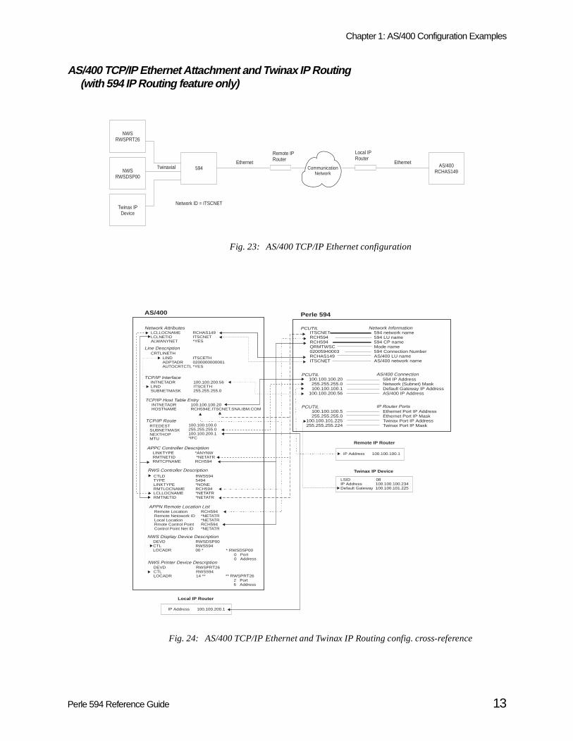
AS/400 TCP/IP Ethernet Attachment and Twinax IP Routing (with 594 IP Routing feature only)
Fig. 23: AS/400 TCP/IP Ethernet configuration
Fig. 24: AS/400 TCP/IP Ethernet and Twinax IP Routing config. cross-reference
NWSRWSPRT26
594 AS/400RCHAS149
Twinax IPDevice
Twinaxial
Network ID = ITSCNET
Remote IPRouter
CommunicationNetwork
Local IPRouter
Ethernet Ethernet
NWSRWSDSP00
Perle 594
PCUTIL594 network name594 LU name594 CP nameMode name594 Connection NumberAS/400 LU nameAS/400 network name
ITSCNETRCH594RCH594QRMTWSC02005940003RCHAS149ITSCNET
Network Information
AS/400
LCLLOCNAMELCLNETIDALWANYNET
RCHAS149ITSCNET*YES
CRTLINETHLINDADPTADRAUTOCRTCTL
ITSCETH0200000000001*YES
Network Attributes
Line Description
LINKTYPERMTNETIDRMTCPNAME
APPC Controller Description*ANYNW*NETATR
RCH594
100.100.100.5255.255.255.0
100.100.101.225255.255.255.224
PCUTILEthernet Port IP AddressEthernet Port IP MaskTwinax Port IP AddressTwinax Port IP Mask
IP Router Ports
INTNETADRLINDSUBNETMASK
TCP/IP Interface100.100.200.56ITSCETH255.255.255.0
INTNETADRHOSTNAME
TCP/IP Host Table Entry100.100.100.20RCH594E.ITSCNET.SNA.IBM.COM
TCP/IP RouteRTEDESTSUBNETMASKNEXTHOPMTU
100.100.100.0255.255.255.0100.100.200.1*IFC
Twinax IP Device
LSID 08IP Address 100.100.100.234Default Gateway 100.100.101.225
CTLDTYPELINKTYPERMTLOCNAMELCLLOCNAMERMTNETID
RWS5945494*NONERCH594*NETATR*NETATR
RWS Controller Description
DEVDCTLLOCADR
RWSDSP00RWS59400 * * RWSDSP00
0 Port0 Address
NWS Display Device Description
** RWSPRT262 Port6 Address
DEVDCTLLOCADR
RWSPRT26RWS59414 **
NWS Printer Device Description
Local IP Router
IP Address 100.100.200.1
APPN Remote Location ListRemote LocationRemote Netowork IDLocal LocationRmote Control PointControl Point Net ID
RCH594*NETATR*NETATRRCH594*NETATR
100.100.100.20255.255.255.0100.100.100.1
100.100.200.56
PCUTIL594 IP AddressNetwork (Subnet) MaskDefault Gateway IP AddressAS/400 IP Address
AS/400 Connection
Remote IP Router
IP Address 100.100.100.1
Perle 594 Reference Guide 13

Chapter 1: AS/400 Configuration Examples
AS/400 TCP/IP Frame Relay Attachment
Fig. 25: AS/400 TCP/IP Frame Relay configuration
Fig. 26: AS/400 TCP/IP Frame Relay config. cross-reference
NWSRWSPRT26
594e AS/400RCHAS149
NWSRWSDSP00
Twinaxial
Network ID = ITSCNET
Frame RelayNetwork
Token-Ring
Local IPRouter
Perle 594
PCUTIL594 network name594 LU name594 CP nameMode name594 Connection NumberAS/400 LU nameAS/400 network name
ITSCNETRCH594RCH594QRMTWSC40005940003RCHAS149ITSCNET
Network Information
AS/400
LCLLOCNAMELCLNETIDALWANYNET
RCHAS149ITSCNET*YES
CRTLINTRNLINDADPTADRAUTOCRTCTL
ITSCTRN400000000149*YES
Network Attributes
Line Description
LINKTYPERMTNETIDRMTCPNAME
APPC Controller Description*ANYNW*NETATR
RCH594
100.100.100.20255.255.255.0100.100.100.2100.200.200.56
PCUTIL594 IP AddressNetwork (Subnet) MaskDefault Gateway IP AddressAS/400 IP Address
AS/400 Connection
INTNETADRLINDSUBNETMASK
TCP/IP Interface100.200.200.56ITSCTRN255.255.0.0
INTNETADRHOSTNAME
TCP/IP Host Table Entry100.100.100.20RCH594.ITSCNET.SNA.IBM.COM
TCP/IP RouteRTEDESTSUBNETMASKNEXTHOPMTU
100.100.100.0255.255.255.0100.200.200.2*IFC
CTLDTYPELINKTYPERMTLOCNAMELCLLOCNAMERMTNETID
RWS5945494*NONERCH594*NETATR*NETATR
RWS Controller Description
DEVDCTLLOCADR
RWSDSP00RWS59400 * * RWSDSP00
0 Port0 Address
NWS Display Device Description
** RWSPRT262 Port6 Address
DEVDCTLLOCADR
RWSPRT26RWS59414 **
NWS Printer Device Description
Local IP Router
Token-Ring PortIP Address 100.200.200.2IP Mask 255.255.0.0
Frame Relay PortIP Address 100.100.100.2IP Mask 255.255.255.0
APPN Remote Location ListRemote LocationRemote Netowork IDLocal LocationRemote Control PointControl Point Net ID
RCH594*NETATR*NETATRRCH594*NETATR
14 Perle 594 Reference Guide

e 594.
nly.
twork
meriction.
engthmber,to the
gth isPC
twelveoller
hichE) in eachrs: 0—
nticaltical
Chapter 2: Understanding Configuration Parameters
This chapter contains an alphabetical list (by keyword) of configuration parameters for the Perl
594 address format
When connecting the Perle 594 to an Ethernet LAN you can use one of two formats:
• Use Ethernet format if the LAN connection between your controller and host is Ethernet o
• Use Token-Ring format:
• if your controller is attached to Ethernet and there are Token-Ring segments in your ne
• your network is designed to use the Token-Ring address format.
The order of the bits in each byte is reversed when you use the Token-Ring address format.
594 connection number
The 594 connection number is used as follows:
• for X.21 connections it specifies the telephone number of the Perle 594
• for LAN connections it specifies the Perle 594 LAN address
• for X.25 connections it specifies the network address of the Perle 594.
Set the 594 connection number as follows:
• SDLC Leased connections—The 594 connection number is not used.
• SDLC Switched/Manual Dial connections—The 594 connection number is not used.
• SDLC switched using V.25 bis
• X.25 connections—enter the network address of the Perle 594. Field length is up to 15 nucharacters 0—9. Match to the CNNNBR parameter in the AS/400 APPC controller descrip
• X.21 Switched connections—enter the network telephone number (calling number). Field lis four to fourteen numeric characters 0—9. The number must be the FULL international nuincluding the network ID (or country code), excluding any additional access codes. Match CNNNBR parameter in the AS/400 APPC controller description.
• Token-Ring AS/400 attachment—enter the Token-Ring address of the Perle 594. Field lentwelve characters: 0—9, A—F. Match to the ADPTADR parameter in the AS/400 APcontroller description.
• Ethernet attachment—enter the 594 Ethernet address of the Perle 594. Field length is characters: 0—9, A—F. Match to the ADPTADR parameter in the AS/400 APPC contrdescription.
• X.21 Leased connections—The 594 connection number is not used.
594 CP Name
Specifies the control point name of the Perle 594 controller and identifies it to the AS/400 with wit communicates. This parameter MUST match the remote control point name (RMTCPNAMthe AS/400 APPC controller description. When the Perle 594 emulates multiple controllers,emulated controller requires a unique control point name. Field length is up to eight characte9, A—Z, $, # and @.
Note : Perle recommends that the RMTLOCNAME and RMTCPNAME parameters use idenames to correlate the APPC controller with an RWS controller. If you do not use idennames, an entry in the Remote Configuration List is required.
Perle 594 Reference Guide 15
Chapter 2: Understanding Configuration Parameters
ult is
eoller
ther by afy theoose
terNIC
Perle9, A—troller match, each
ameter to 8
er must
latedecimale 594
rle 594e line
. Unlesstation
e 594mberr musttion,
urrent is not
594 Ethernet address
Specifies the last 8 characters of the Ethernet feature card LAN address. The defa0200494000XX, where XX=the slot number of the card and the first four characters are either 0200(for Ethernet address format) or 4000 (for Token-Ring address format). Field length is twelvcharacters: 0—9, A—F. MUST match the ADPTADR parameter on the AS/400 APPC contrdescription.
594 IP Address
The IP address consists of 4 numbers each between 0-255 which are separated from each operiod. One or more of the numbers identify the network, while the remaining numbers identicontroller (or host). If you do not plan on attaching your network to the internet, then you may chany address you like. Otherwise, the network portion of your IP address must be assigned by InRegistration Services.
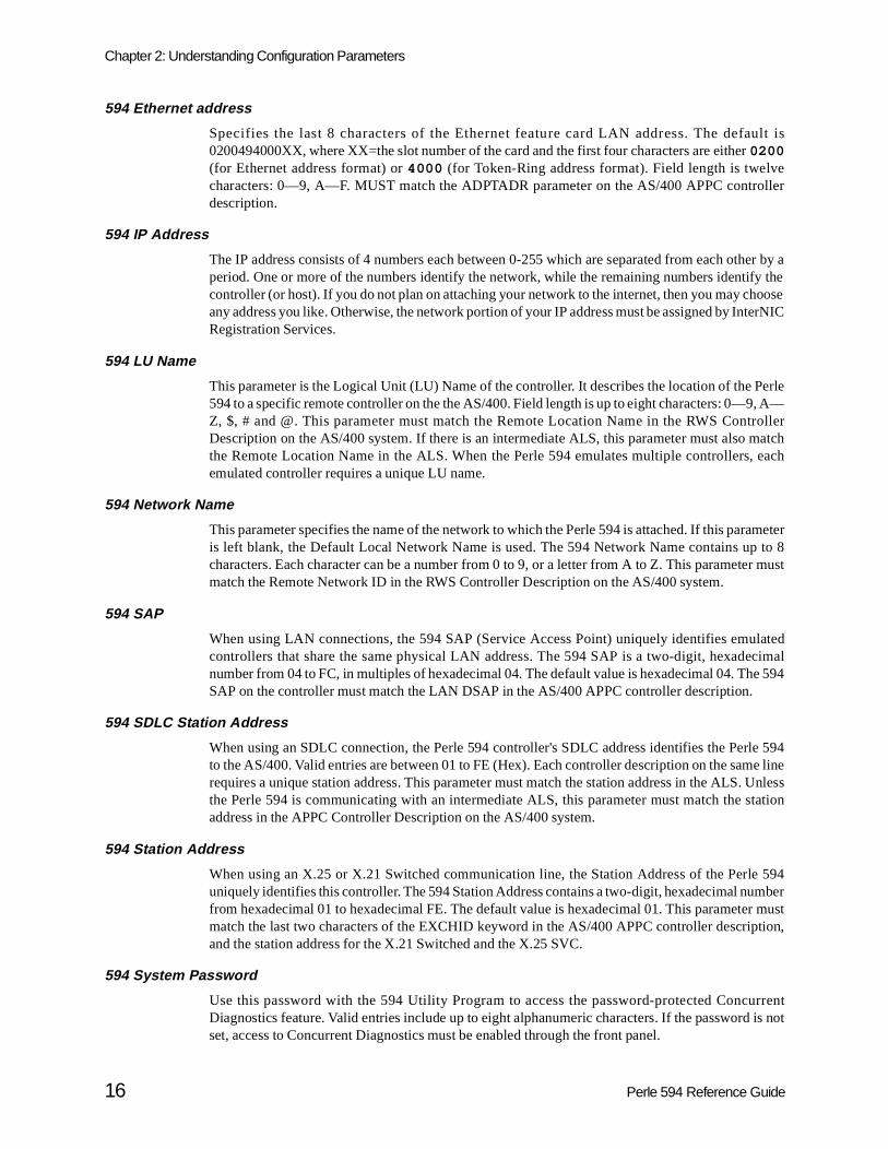
594 LU Name
This parameter is the Logical Unit (LU) Name of the controller. It describes the location of the 594 to a specific remote controller on the the AS/400. Field length is up to eight characters: 0—Z, $, # and @. This parameter must match the Remote Location Name in the RWS ConDescription on the AS/400 system. If there is an intermediate ALS, this parameter must alsothe Remote Location Name in the ALS. When the Perle 594 emulates multiple controllersemulated controller requires a unique LU name.
594 Network Name
This parameter specifies the name of the network to which the Perle 594 is attached. If this paris left blank, the Default Local Network Name is used. The 594 Network Name contains upcharacters. Each character can be a number from 0 to 9, or a letter from A to Z. This parametmatch the Remote Network ID in the RWS Controller Description on the AS/400 system.
594 SAP
When using LAN connections, the 594 SAP (Service Access Point) uniquely identifies emucontrollers that share the same physical LAN address. The 594 SAP is a two-digit, hexadnumber from 04 to FC, in multiples of hexadecimal 04. The default value is hexadecimal 04. ThSAP on the controller must match the LAN DSAP in the AS/400 APPC controller description.
594 SDLC Station Address
When using an SDLC connection, the Perle 594 controller's SDLC address identifies the Peto the AS/400. Valid entries are between 01 to FE (Hex). Each controller description on the samrequires a unique station address. This parameter must match the station address in the ALSthe Perle 594 is communicating with an intermediate ALS, this parameter must match the saddress in the APPC Controller Description on the AS/400 system.
594 Station Address
When using an X.25 or X.21 Switched communication line, the Station Address of the Perluniquely identifies this controller. The 594 Station Address contains a two-digit, hexadecimal nufrom hexadecimal 01 to hexadecimal FE. The default value is hexadecimal 01. This parametematch the last two characters of the EXCHID keyword in the AS/400 APPC controller descripand the station address for the X.21 Switched and the X.25 SVC.
594 System Password
Use this password with the 594 Utility Program to access the password-protected ConcDiagnostics feature. Valid entries include up to eight alphanumeric characters. If the passwordset, access to Concurrent Diagnostics must be enabled through the front panel.
16 Perle 594 Reference Guide

Chapter 2: Understanding Configuration Parameters
nter is
of theeft blank Line
nly.
twork
e fromr that two-slations
Aborted Frames
If during a data frame, there is an occurrence of more than six logical 1s in a row, this couincremented by 1.
Access Code
For X.21 Switched communications, this parameter is the international access country codephone number. The access code is a number between 0 and 999. This parameter can be l(default) if no access code is required. Match this field to the SHMACC keyword on the AS/400Description.
Address Format
When connecting the Perle 594 to an Ethernet LAN you can use one of two formats:
• Use Ethernet format if the LAN connection between your controller and PWS is Ethernet o
• Use Token-Ring format:
• if your controller is attached to Ethernet and there are Token-Ring segments in your ne
• your network is designed to use the Token-Ring address format.
The order of the bits in each byte is reversed when you use the Token-Ring address format.
Alternate Keyboard Translations
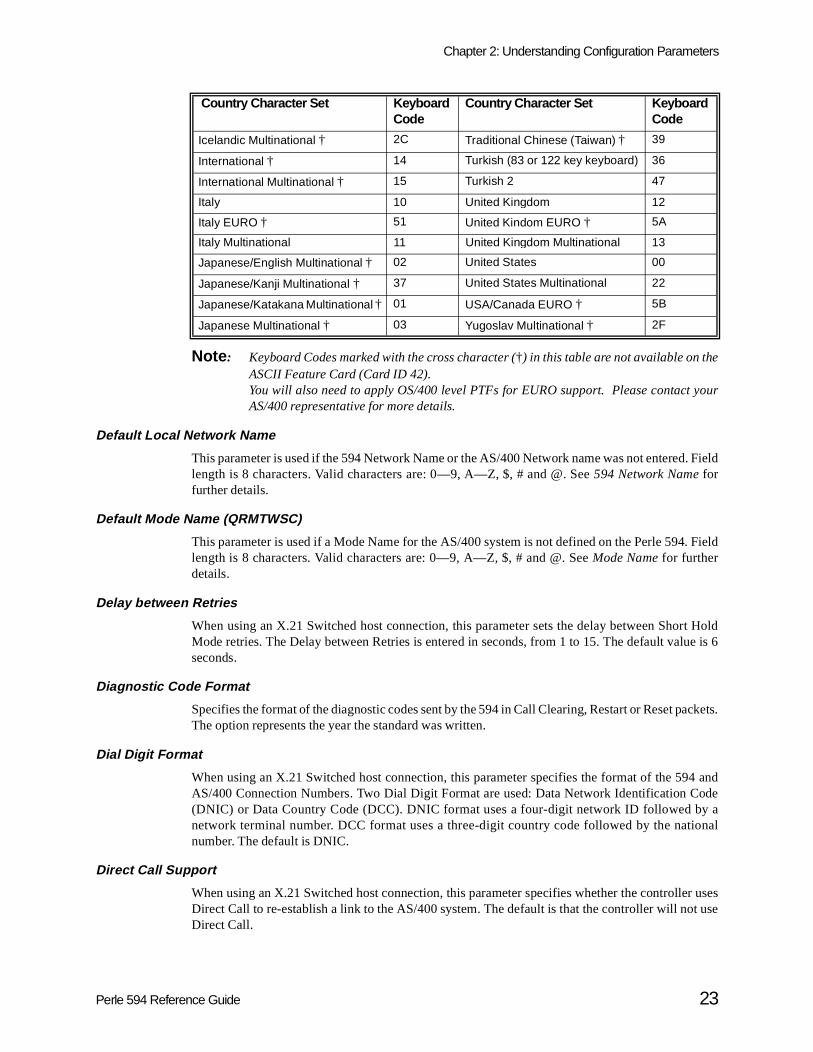
Enter a two-digit code in this parameter to enable use of a keyboard with a different languagthe default keyboard type. If an Alternate Keyboard Translation is not specified, the NWSs focontroller use the Default Keyboard Translation. The Keyboard Translation is identified by adigit code, called a Keyboard Code. To use this feature the default and alternate keyboard tranmust be multinational codes. These codes are listed in the following table:
Country Character Set Keyboard Code
Albania † 3E
Austria/Germany Multinational 21
Belgium Multinational † 07
Canada/English Multinational 22
Canada/French Multinational 09
Denmark Multinational 0B
Finland Multinational 0D
France (AZERTY) Multinational 05
France (QWERTY) Multinational † 1B
Icelandic Multinational † 2C
International Multinational † 15
Italy Multinational 11
Japanese/English Multinational † 02
Japanese/Kandy Multinational † 37
Japanese/Katahdin Multinational † 01
Japanese Multinational † 03
Latin America Multinational † 0F
Netherlands Multinational 2E
Norway Multinational 17
Portugal Multinational 19
Perle 594 Reference Guide 17

Chapter 2: Understanding Configuration Parameters
n the
r. Ther this
Notes : Keyboard Codes marked with the cross character (†) in this table are not available oASCII Feature Card (Card ID 42).
Up to three alternate keyboard translations can be used for each emulated controlleAlternate Keyboard Translations parameter must match the keyboard translation foNWS on the AS/400 system.
AS/400 Connection Number
The AS/400 connection number is used as follows:
• for synchronous dial connections it specifies the telephone number of the network
• for LAN connections it specifies the host LAN address
• for X.25 connections it specifies the network address of the ALS.
Set the AS/400 connection number as follows:
Spain Multinational 1D
Sweden Multinational 1F
Swiss/French Multinational 28
Swiss/German Multinational 2A
United Kingdom Multinational 13
United States Multinational 22
Yugoslav Multinational † 2F
SDLC Switched connections Enter the network telephone number (calling number). Fieldlength is up to 64 characters 0 - 9,:, <, =, >, P, T, and &. Matchto the CNNNBR parameter in the AS/400 Line Description. No entry is needed if the network does not require this parameter.
X.25 connections Enter the network address of the ALS. Field length is up to 15characters 0—9. Match to the NETADR parameter in the AS/400 Line Description
X.21 Switched connections For an Address Call, enter the network telephone number (calling number). Field length is from four to fourteen numeric characters 0—9. The number must be the FULL international number, including the network ID (or country code), excluding any additional access codes. Match to the CNNNBR parameter in the Line Description. For Direct Call, use the value DC for this parameter.
Token-Ring AS/400attachment
Enter the 594 Token-Ring address of the ALS. Field length istwelve characters: 0—9, A—F. Match to the ADPTADR parameter in the AS/400 Line Description.
Ethernet attachment Enter the 594 Ethernet address of the ALS. Field length is twelve characters: 0—9, A—F. Match to the ADPTADR parameter in the AS/400 Line Description.
SDLC Leased connections The AS/400 connection number is not used
X.21 Leased connections The AS/400 connection number is not used.
Countr y Character Set Ke yboard Code
18 Perle 594 Reference Guide
Chapter 2: Understanding Configuration Parameters
nicate DLCI
s eightLine
ther by afy theoose
terNIC
ighton theme in
n it isameber fromwork
ntifiesC, in
troller
can be
t usesTALKomm.
ciatedd upon same asbled for
AS/400 Data Link Connection Identifier (DLCI)
An identifier assigned to the link between the 594 and the network so the controller can commuwith the host using the Frame Relay protocol. If the 594 is attached directly to the host, the 594'sand the host's DLCI must match.
AS/400 Ethernet Address
Specifies the Ethernet address which is used for communicating with the AS/400. Field length icharacters: 0—9, A—Z. This field must match the ADPTADR parameter in the AS/400 Description.
AS/400 IP Address
The IP address consists of 4 numbers each between 0-255 which are separated from each operiod. One or more of the numbers identify the network, while the remaining numbers identicontroller (or host). If you do not plan on attaching your network to the internet, then you may chany address you like. Otherwise, the network portion of your IP address must be assigned by InRegistration Services.
AS/400 LU Name
This parameter is the Logical Unit (LU) Name of the host AS/400. Field length is up to echaracters: 0—9, A—Z, $, # and @. This parameter must match the Local Location Name AS/400. If there is an intermediate ALS, this parameter must also match the Local Location Nathe ALS.
AS/400 Network Name
This parameter is the name of the network to which the AS/400 system is attached whecommunicating with the Perle 594. If this parameter is left blank, the Default Local Network Nis used. The AS/400 Network Name contains up to 8 characters. Each character can be a num0 to 9, or a letter from A to Z. This parameter must match the Local Network ID under NetAttributes on the AS/400 system.
AS/400 SAP
When using a LAN connection to the host, the AS/400 SAP (Service Access Point) uniquely idethe host to the Perle 594. The AS/400 SAP is a two-digit, hexadecimal number from 04 to Fmultiples of hexadecimal 04. The default value is hexadecimal 04. The AS/400 SAP on the conmust match the LAN SSAP in the AS/400 APPC controller description.
Note: There is no relation between the AS/400 SAP and 594 SAP, therefore, the values either identical or unique.
ASCII Keyboard Translation
See Default Keyboard Translation.
ASCII Display Type
When using an ASCII Feature Card, this parameter defines the type of terminal emulator thathis port. The emulator may be an enhanced emulator software such as PerleTALK and Perlefor Windows, an adapter handler for Client Access, or an ASCII terminal emulator such as Proc
Associated Group
A Group is a name that identifies one or more ports with identical configurations. All ports assowith Groups are placed into a pool of ports whose characteristics can be dynamically changeconnection by selecting an associated group. The session characteristics of the group are thethose of the ports to which they are associated. When dialing into a port that has been ena
Perle 594 Reference Guide 19
Chapter 2: Understanding Configuration Parameters
orts notup are
e haso ensurers.
nd the
Circuit
by theconnectup to 8nter a
events, which
s auto-
t a call.
sence
u are
or astem.
r
nt
e
group operations, the user is prompted for the Group name. The Perle 594 then scans all pcurrently in use to find one with a matching group name. The session characteristics of the grothen assigned to the port.
A Group name is 1 to 8 alphanumeric characters, beginning with a letter. If the Group namalready been defined on another port, then the emulation parameters for this port are checked tthat they match the other ports in the Group. If they are not identical, an error message appea
Baud Rate
This parameter specifies the speed at which information is exchanged between this port amodem to which it is attached.
Circuit Type
This parameter specifies the type of X.25 circuit you will use to access the AS/400 system. The Type will be one of the following:
Connect Password
The ASCII Feature Card can control access to the 594 by requiring a password to be entereduser at connect time. This is enabled by entering a password in the Connect Password field. At time, if the password is incorrectly entered, the user is denied access. The password is alphanumeric characters in length. If you leave this field blank, users will not be prompted to epassword when they connect to this port.
Note : The Connect Password is independent of the AS/400 sign on password, which prunauthorized persons from accessing the AS/400 system, and the X.25 passworduniquely identifies individual controllers to the X.25 network.
Connection Method
For synchronous host connections, this parameter specifies the way your modem controlanswer.
• In the DTR mode, the Perle 594 enables the DTR signal to indicate its readiness to accep
• In the CDSTL mode, the Perle 594 waits for an enabled calling indicator that shows the preof an incoming call.
DTR method is the most commonly used method by modems for controlling auto-answer. If younsure, refer to your modem documentation or contact your Network supplier.
Connection Type
This parameter specifies whether your SDLC or X.21 leased line is a point-to-point linemultipoint line. This parameter must match the setting in the Line Description on the AS/400 syThe connection type correlates with the line facility.
SVC A manual command is required from the Perle 594 to place outgoing call oto answer incoming Switched Virtual Circuit (SVC) calls.
PVC A manual command is required from the Perle 594 to establish a PermaneVirtual Circuit (PVC) link to the AS/400 system.
SVCIN Incoming Switched Virtual Circuit calls are automatically answered by thePerle 594.
PVC AUTO When the Perle 594 is powered on, the Permanent Virtual Circuit link to thAS/400 system is established automatically.
20 Perle 594 Reference Guide

Chapter 2: Understanding Configuration Parameters
em. It muste is
0 line
em. It CNNrollersllers.
logical
link is
if a
g (i.e.,
ittershat ares usingin the
ed forn the
nicate DLCI
r each
A point-to-point line is a data link that connects a single remote controller with an AS/400 systcan be a non-switched or switched connection. If your line is non-switched point-to-point, youspecify *NONSWTPP for the CNN parameter defined in the AS/400 line description. If your linswitched point-to-point, you must specify *SWTPP for the CNN parameter defined in the AS/40description.
A multipoint line is a data link that connects 2 or more remote controllers with an AS/400 systis considered a non-switched connection and is always leased. Specify multipoint (*MP) for theparameter; the MAXCTL parameter must equal the total number of physical and emulated conton the line. You must specify multipoint if a single Perle 594 is emulating multiple remote contro
Continuous Retry
This parameter specifies whether the Perle 594 continuously attempts to re-establish a connection to the AS/400 if the logical connection is lost. When Continuous Retry is set to Yes, thecontroller will attempt every 10 minutes to re-establish the connection as long as the physicalstill active.
It is recommended that Yes be selected if your AS/400 is unavailable for extended periods, orleased line is used.
Data Encoding
This parameter specifies the type of Data Encoding that your SDLC or X.21 leased line is usinNRZI or NRZ). This parameter must match the setting on the AS/400 Line Description.
NRZI specifies that non-return-to-zero inverted data encoding is used. NRZI can allow transmand receivers to better maintain synchronization and may be required by some modems tsensitive to certain bit patterns in the data stream. Normally, analog connections (connectionmodems) should specify NRZI data encoding. Specify *YES for the NRZI parameter defined AS/400 line description.
NRZ specifies that (non-return-to-zero) inverted data encoding is not used. NRZ is recommenduse with digital data circuit-terminating equipment and networks such as X.21. Specify *NO iNRZI parameter defined in the AS/400 line description.
Note: All equipment on the same line must specify the same data encoding method.
Data Link Connection Identifier (DLCI)
An identifier assigned to the link between the 594 and the network so the controller can commuwith the host using the Frame Relay protocol. If the 594 is attached directly to the host, the 594'sand the host's DLCI must match.
Default Controller Address
When defining a multisession controller, this parameter is the default controller address fomultisession. For more information, see Multisession Assignment.
Default Gateway IP Address
The value of the router while linking the controller to the remote host.
Perle 594 Reference Guide 21

Chapter 2: Understanding Configuration Parameters
rds. Theardsing an
Default Keyboard Translation
For NWS attachment, this parameter defines the language and layout of the attached keyboaKeyboard Translation is identified by a two-digit code, called a Keyboard Code. All keyboattached to this emulated controller will share this Keyboard Code unless defined as usAlternate Keyboard Translation. These codes are listed in the following table:
Country Character Set Keyboard Code
Country Character Set Keyboard Code
Albania † 3E Korea † 38
Austria/German EURO † 49 Latin 2 34
Austria/Germany 20 Latin America † 0E
Austria/Germany Multinational 21 Latin America Multinational † 0F
Belgium Multinational † 07 Macedonia (Cyrillic) † 42
Belgium Multinational EURO † 4A Netherlands 2D
Brazil † 3C Netherlands EURO † 52
Brazil EURO † 4B Netherlands Multinational 2E
Bulgaria (Cyrillic) † 3F Norway 16
Canada/English 00 Norway EURO † 53
Canada/English Multinational 22 Norway Multinational 17
Canada/French 08 Poland † 43
Canada/French Multinational 09 Portugal 18
Canadian French Multinational EURO †
4C Portugal EURO † 54
Cyrillic † 31 Portugal Multinational 19
Czech † 40 Romania † 44
Denmark 0A Russia (Cyrillic) † 45
Denmark EURO † 4D Serbia (Cyrillic) † 48
Denmark Multinational 0B Simplified Chinese † 3A
Finland 0C Slovakia † 46
Finland EURO † 4F Spain 1C
Finland Multinational 0D Spain EURO † 58
France (AZERTY) 04 Spain Multinational 1D
France (AZERTY) EURO † 4E Spanish Speaking (Latin America EURO) †
57
France (AZERTY) Multinational 05 Sweden 1E
France (QWERTY) † 1A Sweden EURO † 59
France (QWERTY) Multinational † 1B Sweden Multinational 1F
Greek † 32 Swiss/French Multinational 28
Greek 2 3B Swiss/French Multinational EURO †
55
Hungary † 41 Swiss/German Multinational 2A
Iceland EURO † 50 Swiss/German Multinational EURO †
56
Icelandic † 2B Thai † 35
22 Perle 594 Reference Guide
Chapter 2: Understanding Configuration Parameters
your
. Field
. Field
rt Holdlue is 6
ackets.
94 andode
y aional
er usest use
Note : Keyboard Codes marked with the cross character (†) in this table are not available on theASCII Feature Card (Card ID 42). You will also need to apply OS/400 level PTFs for EURO support. Please contactAS/400 representative for more details.
Default Local Network Name
This parameter is used if the 594 Network Name or the AS/400 Network name was not enteredlength is 8 characters. Valid characters are: 0—9, A—Z, $, # and @. See 594 Network Name forfurther details.
Default Mode Name (QRMTWSC)
This parameter is used if a Mode Name for the AS/400 system is not defined on the Perle 594length is 8 characters. Valid characters are: 0—9, A—Z, $, # and @. See Mode Name for furtherdetails.
Delay between Retries
When using an X.21 Switched host connection, this parameter sets the delay between ShoMode retries. The Delay between Retries is entered in seconds, from 1 to 15. The default vaseconds.
Diagnostic Code Format
Specifies the format of the diagnostic codes sent by the 594 in Call Clearing, Restart or Reset pThe option represents the year the standard was written.
Dial Digit Format
When using an X.21 Switched host connection, this parameter specifies the format of the 5AS/400 Connection Numbers. Two Dial Digit Format are used: Data Network Identification C(DNIC) or Data Country Code (DCC). DNIC format uses a four-digit network ID followed bnetwork terminal number. DCC format uses a three-digit country code followed by the natnumber. The default is DNIC.
Direct Call Support
When using an X.21 Switched host connection, this parameter specifies whether the controllDirect Call to re-establish a link to the AS/400 system. The default is that the controller will noDirect Call.
Icelandic Multinational † 2C Traditional Chinese (Taiwan) † 39
International † 14 Turkish (83 or 122 key keyboard) 36
International Multinational † 15 Turkish 2 47
Italy 10 United Kingdom 12
Italy EURO † 51 United Kindom EURO † 5A
Italy Multinational 11 United Kingdom Multinational 13
Japanese/English Multinational † 02 United States 00
Japanese/Kanji Multinational † 37 United States Multinational 22
Japanese/Katakana Multinational † 01 USA/Canada EURO † 5B
Japanese Multinational † 03 Yugoslav Multinational † 2F
Countr y Character Set Ke yboard Code
Countr y Character Set Ke yboard Code
Perle 594 Reference Guide 23
Chapter 2: Understanding Configuration Parameters
nicate DLCI
t haveif a userime the
vity.
orts ate a
that has could
t timer.ession
nabled,er user
Card
ay. The lengththernet
al areaion 2.002.3
ich the
the initial and if
n the
DLCI
An identifier assigned to the link between the 594 and the network so the controller can commuwith the host using the Frame Relay protocol. If the 594 is attached directly to the host, the 594'sand the host's DLCI must match.
Enable Inactivity Time Limit
This option specifies whether the ASCII Feature Card automatically disconnects devices thabeen inactive for a specified period of time. This can prevent unnecessary telephone charges fails to properly disconnect their device or modem. The time limit is specified in the Inactivity TLimit field. When the time limit is reached, the ASCII Feature Card notifies the AS/400 ofdisconnection and ends the session.
Select No to disable the Inactivity Time Limit. The connection will never be dropped due to inacti
Enable Passthrough Printer
When using an ASCII Feature Card, this option specifies whether or not this dial-in port supppassthrough printer. Select Yes to allow users who have a printer attached to their PC to emula5250 printer. Select No if this port will not support a passthrough printer.
Enable Reconnect Time Limit
With the ASCII Feature Card, this option specifies whether a user can reconnect to a session been inadvertently disconnected. When dialing in to an ASCII port, it is possible that a sessionbe disrupted due to a dial-in line problem. If Enable Reconnect Time Limit is set to Yes, the ASCIIFeature Card will keep the AS/400 session active with the host for the duration of the ReconnecIf a user dials in before the Reconnect timer expires, the user will return to the point in their swhere the disruption occurred.
If multiple users have access to this port, it is recommended that the Reconnect Time Limit be eand that it be set for immediate disconnection by setting the value to zero. Otherwise, anothmay accidentally gain access to the AS/400 session before the original user can reconnect.
Select No to disable the Reconnect Time Limit. When a disconnection occurs, the ASCII Featuremaintains the AS/400 session indefinitely.
Ethernet address
This is the Ethernet address of the Perle 594 Ethernet Feature Card when used as a LAN gatewdefault address is 0200494000xx, where xx is the slot number of the Feature Card. The fieldis twelve characters: 0—9, A—F. All PWSs on the same Ethernet gateway must use the same Eaddress.
Ethernet Frame Format
This field is used to identify the Ethernet frame type or standard to be used on the Ethernet locnetwork. The Perle 594 supports the Ethernet IEEE 802.3 standard and the Ethernet versstandard by DEC, Intel, & Xerox (DIX) corporations. The advantages of specifying the IEEE 8standard is that it supports frame sequencing, flow control, and error recovery capabilities whDIX version 2 standard does not support.
A third option supported by the Perle 594 is AUTO CONFIG. The Auto Configure option allowsPerle 594 to automatically adjust to the frame type being used by the AS/400. However, theconnection to the AS/400 may be a little slower since the Perle 594 tries one frame type first,no response is received, it tries the other frame type.
Unless AUTO CONFIG is specified, this field must match the ETHSTD parameter defined iAS/400 Line Description.
24 Perle 594 Reference Guide

Chapter 2: Understanding Configuration Parameters
d with
Flow holdta. Thech the
r to
ntrol
the
tached
s more) is
o the full
on onval, assage,
er ofred, the
) value.ecified
ctivity
emainature
properlyctivity
FCS Error Count
If the FCS (Frame Check Sequence) is incorrect, this counter is incremented by 1.
Fill In Default Values
When defining a multisession value, this setting will cause the multisession addresses to be filledefault values. For more information, please see Multisession Assignment.
Flow Control
This ASCII Feature Card option specifies the type of flow control that will be used on this port. Control is a way for a receiving device to temporarily halt the flow of data so that its capacity todata is not exceeded. The Hardware method uses hardware signals to control the flow of daXon/Xoff method uses software messages to control the flow of data. This setting must matsetting on the modem and on the remote ASCII display.
Should you wish to use software flow control (i.e., Xon/Xoff) with your modem, you should refeyour modem's user guide and modify the Modem Initialization String field.
Flow Control Negotiation Allowed
This feature lets you alter packet size and packet window size. If the network allows flow conegotiation, you can change the packet size and packet window size from call to call.
Frame Relay LMI Mode
Select which LMI (Link Management Interface) mode will be used for the 594. LMI specifiesexchange of management-related information.
Note : The mode you select must match the mode configured on the network or, if you atdirectly to the host, the mode must match the mode configured on the AS/400.
Full Inquiry Interval
On a regular basis, the 594 sends to the network a "full" Status Enquiry message that containinformation than is contained in a standard Status Enquiry. Full Inquiry Interval (FULLINQITVthe number of Status Enquiry messages sent between full Status Enquiry messages plus 1 (sStatus Enquiry message will be included in the count).
Inactive Timer (Ti)
When using a LAN connection, the Inactive Timer (Ti) is used to detect an inoperative conditithe LAN. If there has been no data received or transmitted during the Inactive Timer intermessage will be sent to verify that the connection is still active. If there is no response to this methe 594 will wait for the Inactive Timer to expire again, then retry. This will repeat for the numbtimes set by the Retry Count (N2) value. If there is no response after the Retry Count has expi594 will disconnect the link, and will then attempt to re-establish communications.
The inactive timer (Ti) value should be at least 5 to 10 times greater than the response timer (T1Valid entries are from 1 to 99 seconds. The default is 30 seconds. If the response timer (T1) is spas "*", then the default Ti value of 30 seconds is adequate. This field should match the LAN InaTimer (LANINACTMR) parameter defined in the AS/400 APPC controller description.
Inactivity Time Limit
This parameter is the amount of time that the ASCII Feature Card allows the connection to ridle before disconnecting the device from this port. When the time limit is reached, the ASCII FeCard ends the session. This can prevent unnecessary telephone charges if a user fails to disconnect their device or modem. The time is entered in minutes, from 1 to 99. To use the InaTime Limit, set the Enable Inactivity Time Limit field to Yes.
Perle 594 Reference Guide 25

Chapter 2: Understanding Configuration Parameters
rates inn atllowso bey result.
lex ifingle
n, all
data isbeingems.
h the
sed orailableg toa leased
alone
LAN Link Station Status (Gateway)
Displays status of 594-to-workstation link station status.
LAN Link Station Status (Upstream)
Displays status of 594-to-host link station status.
Line Facility
When using a synchronous host line connection, this parameter specifies whether the line opeHalf Duplex or Full Duplex mode. Half Duplex mode allows communication in only one directioa time, but allows more than one physical controller to be attached to a line. Full Duplex acommunication in both directions simultaneously, but only allows one physical controller tattached to the line. In cases where Full Duplex operation can be used, better performance ma
Use Half Duplex if you have more than one physical controller sharing the line. Use Full Dupyou have only one physical controller sharing the line. You may use Full Duplex if you have a s594 on a line, and it is emulating multiple controllers.
This field must match the DUPLEX parameter defined in the AS/400 line description. In additiocommunications equipment on the line should be set accordingly.
Line Speed (valid For Direct Cable Only)
When using a synchronous host line connection, this parameter specifies the speed at whichtransmitted on the communication line. The Line Speed is specified only if the Perle 594 is directly connected to the AS/400 system. Otherwise, the line speed is established by the mod
Valid line speed entries are from 1200 to 128000 bits per second. This field must matcLINESPEED parameter defined in the AS/400 line description.
Line Type
For an SDLC host connection, this parameter specifies the type of line you are using: leaswitched/manual dial. A leased line is permanently allocated to the Perle 594, and is always avfor its use. A switched/manual dial line is a switched point-to-point line that requires dialinestablish a connection between the Perle 594 remote site and the AS/400 site. The default is line.
Link Initiation
This parameter specifies by what means link initiation is accomplished. Either the network performs link initiation; or either the network or the 594 performs link initiation.
Link State/LLC State
Link State: 1 = Disconnected 2 = Define station sent 3 = Define station done 4 = Test sent 5 = Test done 6 = XID sent 7 = XID done 8 = Connected
26 Perle 594 Reference Guide

Chapter 2: Understanding Configuration Parameters
es (I- fromIn a
nter is
counter
litv),
ectly.
ith theannel
a letterpecifynnel.
e Perle Twotroltem.
LLC State: 1 = Reserved 2 = Reserved 3 = Reserved 4 = Closing 5 = Closed 6 = Reserved 7 = Open 9 = Connecting 10 = Connected 11 = Close station
Link Window Size
For an X.25 connection, this parameter specifies the maximum number of information framframes) which can be awaiting acknowledgment at any one time. The Link Window Size can be1 to 7, but must match the Link Window Size specified in your X.25 Network Subscription. network with large transmission delays, a larger Link Window Size may increase throughput.
LMI Protocol Error Count
If the 594 detects an error in the format of an LMI Status Enquiry response message, this couincremented by 1.
LMI Sequence Error Count
If the 594 detects an error in the sequence number of a response to an LMI Status Enquiry, thisis incremented by 1.
LMI Timeout Count
If the network does not respond to a 594 LMI Status Enquiry within the Polling Interval time (Polthis counter is incremented by 1
Local Loopback Supported
Local loopback is a test used to determine if the modem attached to the 594 is operating corr
Logical Channel
For an X.25 connection, this parameter is the logical channel number used for connection wAS/400 system. This parameter is only required for SVC circuits and must match the logical chassigned by your network.
The Logical Channel contains 3 characters. Each character can be a number from 0 to 9, orfrom A to F. The first character specifies the Logical Group Number. The last two characters sthe Logical Channel Number. Each alternate AS/400 system can have a different Logical Cha
Logical Link Control (LLC)
When using an X.25 host connection, this parameter specifies the type of LLC used between th594 and the AS/400. The LLC provides end-to-end link level functions to the SNA protocol.LLCs are supported: Qualified Logical Link Control (QLLC) and Enhanced Logical Link Con(ELLC). The default is QLLC. This parameter must match the LLC specified on the AS/400 sys
Manual Options
These options permit the operator to change call parameters from call to call.
Perle 594 Reference Guide 27

Chapter 2: Understanding Configuration Parameters
amesdicates
ment
hput
e therames
oughmes
tiallynt. An free. Ifnt are
hput
e therames
meterS/400S/400eter
nter is
ationame
, or one
Perle
g on a screen
t to the
Maximum In (N3)
When using a LAN connection, this parameter specifies the maximum number of information frthat the Perle 594 can receive before sending an acknowledgment. An acknowledgment inwhether all frames since the previous acknowledgment were error free. If the acknowledgindicates an error, all frames since the previous acknowledgment are retransmitted.
In an error free network, it is best to set Maximum In to a large value. This will improve througby reducing the number of acknowledgments.
In an error-prone network, it is best to set Maximum In to a small value. This will increasprobability that a successful acknowledgment will be returned, and will reduce the number of fthat must be retransmitted.
The N3 parameter should be half of the Maximum Out (TW) value. Valid entries are from 1 thr4 frames. The default is 1 frame. This field should match the LAN Max Outstanding Fra(LANMAXOUT) parameter defined in the AS/400 APPC controller description.
Maximum Out (TW)
When using a LAN connection, this parameter specifies the maximum number of sequennumbered frames which the controller can send before it must receive an acknowledgmeacknowledgment indicates whether all frames since the previous acknowledgment were errorthe acknowledgment indicates an error, all frames since the previous acknowledgmeretransmitted.
In an error free network, it is best to set Maximum Out to a large value. This will improve thorougby reducing the number of acknowledgments.
In an error-prone network, it is best to set Maximum Out to a small value. This will increasprobability that a successful acknowledgment will be returned, and will reduce the number of fthat must be retransmitted.
The Maximum Out parameter can be from 2 to 8. The default value is 2. The Maximum Out paramust be at least two times as large as the Maximum In (N3) parameter. If you are using a LAN Aattachment and Alternate AS/400 systems, you must enter the Maximum Out value for each Asystem. This field should match the LAN Acknowledgment Frequency (LANACKFRQ) paramdefined in the AS/400 APPC controller description.
Misaddressed Frames
If the 594 receives a frame having an address that the 594 is not configured for, this couincremented by 1.
Mode Name
This Network parameter is the name of the Mode Description which will be used for communicwith the AS/400. The Mode Name defines LU6.2 communications characteristics. A Mode Ncontains up to 8 characters. Each character can be a number from 0 to 9, a letter from A to Zof the following symbols: $, # or @.
An AS/400 predefined mode is supplied for use with remote controllers named QRMTWSC. recommends that you use this mode.
Modem
When using an ASCII Feature Card, this parameter indicates the type of modem you are usinport. Select the Modem which is closest to the type you are using. Codes are listed on the Helpfor this parameter.
Modem Initialization String
When using an ASCII Feature Card, this parameter is a string of characters that will be sen
28 Perle 594 Reference Guide
Chapter 2: Understanding Configuration Parameters
lizedem in
r, thescreen
rt, theoardg the
f theLAN.
oller, port
tationelow.
o this
ysical
rk. Theller is
he year
modem to set up the modem for use on this port. The Modem Initialization String field is initiawhen the modem code is entered. You may customize this string in order to initialize your moda different way. Consult your modem vendor's documentation for details.
Multisession Assignment
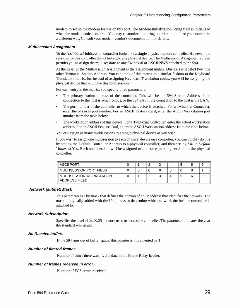
To the AS/400, a Multisession controller looks like a single physical remote controller. Howevesessions for this controller do not belong to any physical device. The Multisession Assignment permits you to assign the multisessions to any Twinaxial or ASCII NWS attached to the 594.
At the heart of the Multisession Assignment is the assignment matrix. One axis is labeled Poother Twinaxial Station Address. You can think of this matrix in a similar fashion to the KeybTranslation matrix, but instead of assigning Keyboard Translation codes, you will be assigninphysical device that will have this multisession.
For each entry in the matrix, you specify three parameters:
• The primary station address of the controller. This will be the 594 Station Address iconnection to the host is synchronous, or the 594 SAP if the connection to the host is via
• The port number of the controller to which the device is attached. For a Twinaxial Contrenter the physical port number. For an ASCII Feature Card, enter the ASCII Workstationnumber from the table below.
• The workstation address of this device. For a Twinaxial Controller, enter the actual worksaddress. For an ASCII Feature Card, enter the ASCII Workstation address from the table b
You can assign as many multisessions to a single physical device as you wish.
If you wish to assign one multisession to each physical device on a controller, you can quickly dby setting the Default Controller Address to a physical controller, and then setting Fill in DefaultValues to Yes. Each multisession will be assigned to the corresponding session on the phcontroller.
Network (subnet) Mask
This parameter is a bit mask that defines the portion of an IP address that identifies the netwomask is logically added with the IP address to determine which network the host or controattached to.
Network Subscription
Specifies the level of the X.25 network used to access the controller. The parameter indicates tthe standard was issued.
No Receive buffers
If the 594 runs out of buffer space, this counter is incremented by 1.
Number of filtered frames
Number of times there was invalid data in the Frame Relay header.
Number of frames received in error
Number of FCS errors received.
ASCII PORT 0 1 2 3 4 5 6 7
MULTISESSION PORT FIELD 0 0 0 0 0 0 0 1
MULTISESSION WORKSTATION ADDRESS FIELD
0 1 2 3 4 5 6 0
Perle 594 Reference Guide 29

Chapter 2: Understanding Configuration Parameters
ore
ore
594.lated
mented
lo 128
6 or 512
andingize can
e usedended
t
e
Number of frames received with BECN
Number of times the BECN (Backward Explicit Congestion Notification) bit in the Frame Relay Cheader was set.
Number of frames received with DE
Number of times the DE (Discard Eligibility) bit in the Frame Relay Core header was set.
Number of frames received with FECN
Number of times the FECN (Forward Explicit Congestion Notification) bit in the Frame Relay Cheader was set.
Number of Multisession Controllers
This parameter is the number of Multisession Controllers which will be emulated by the PerleA maximum of 39 Multisession Controllers can be defined. The total of physical and emucontrollers defined within a single Perle 594 must not exceed 40.
Number of Retries
Number of times T1 timer expired
Number of times the Response Timer expired.
Overruns
If the 594 cannot receive data fast enough to keep up with the data rate, this counter is increby 1.
Packet Level Sequence Numbering
Specifies the set of numbers used to identify packets. Modulo 8 specifies numbers 0-7; moduspecifies numbers 0-127.
Packet Size
This parameter specifies the size of each packet, in bytes. The Packet Size can be 64, 128, 25bytes. The default Packet Size is 128 bytes.
Packet Window Size
When using an X.25 host connection, this parameter specifies the maximum number of outstpackets which can be sent before an acknowledgment must be received. The Packet Window Sbe from 2 to 7. The default value is 2.
Parity
When using an ASCII Feature Card, this parameter sets the type of parity checking that will bon this port. The parity must be the same for the port and the remote ASCII device. It is recomm
X.21 switched When using Short Hold Mode, this parameter is the number of times thathe controller will attempt to re-establish a link to the AS/400 after a Short Hold disconnect. The Number of Retries can be from 0 to 255. Thdefault value is 5 retries.
X.25 This parameter is the number of times that the controller will resend atransmitted frame that was not successfully received. The Number of Retries can be from 0 to 255. The default value is 10 retries.
30 Perle 594 Reference Guide
Chapter 2: Understanding Configuration Parameters
nectedonnect,owsd in the
t willype of/400
e Perle linkwordrefore,
ter is
ter is
LITV)
s willdress.
waits as soonsend anPerlece on
S/400llerponse must
that parity be set to None unless your remote device explicitly requires another setting.
Passthrough ASCII Printer Type
When using an ASCII Feature Card, this parameter defines the type of printer that will be conto the remote PC for use as a Passthrough printer. If the printer type is defined as Select at Cthe user will be prompted at connect time for the printer type. Note that for PerleTALK for Windand PC Support/400, this parameter has no effect as the Passthrough printer type is defineremote emulator.
Passthrough Printer Emulation
When using an ASCII Feature Card, this parameter specifies the type of IBM 5250 printer thabe emulated on this port. Any of the listed IBM printers can be emulated, regardless of the tASCII printer that will actually be used. The corresponding printer device description on the ASsystem must be configured as the same type.
Password
When using an X.25 host connection, and there are multiple emulated controllers defined for th594, this parameter is used to uniquely identify this controller to the X.25 network duringestablishment. It is only required when Switched Virtual Circuits (SVC) are being used. A passis necessary with an SVC since the Logical Channel number is assigned dynamically and, thecannot be used to identify a specific controller.
This parameter is not required if the Perle 594 is emulating a single controller.
PM CTS Error Count
If the CTS signal is dropped by the modem connecting the 594 to the network, this counincremented by 1.
PM DSR Error Count
If the DSR signal is dropped by the modem connecting the 594 to the network, this counincremented by 1.
Polling Interval
The 594 repeatedly sends a Status Enquiry message to the network. The Polling Interval (POLvalue is the number of seconds between Status Enquiry messages.
Printer Port and Station
When using the NWS Configurator, this field identifies the printer to which configuration screenbe sent during a Print Screen. This field specifies the following: port address and workstation ad
Receiver Acknowledgment Timer (T2)
When using a LAN connection, T2 specifies the maximum amount of time that the Perle 594before sending acknowledgments to the sender. The Perle 594 will send an acknowledgmentas the T2 timer expires. Before the T2 timer expires, the Perle 594 determines whether it can acknowledgment along with an information frame. If an information frame is not available, the 594 will only send an acknowledgment. Therefore, a larger T2 value could improve performanthe network by reducing the number of frames.
If the LAN connection is to the host, the T2 timer must be set to a value that is less than the ALAN Response Timer (LANRSPTMR) parameter defined in the AS/400 APPC controdescription. This is to ensure that an acknowledgment is received before the AS/400 LAN restimer expires. If the AS/400 LAN Response Timer expires, the link will be lost and the Perle 594attempt to re-establish communications again.
Perle 594 Reference Guide 31

Chapter 2: Understanding Configuration Parameters
atchC
/400ect to
rd will
rd will
counter
r ans equalnumbere buffer
ponsek, andill be
fected. to wait
ypical,ffected Perle
400
temptscifiedts to re-
k, youTY)
S/400.
Valid entries are from 1 to 255 milliseconds. The default is 30 milliseconds. This field should mthe LAN Acknowledgment Timer (LANACKTMR) parameter defined in the AS/400 APPcontroller description.
Reconnect Time Limit
This parameter is the amount of time during which the ASCII Feature Card will maintain the ASsession following an inadvertent disconnection. While this timer is active, the user can reconnthe port and continue the AS/400 session. After the time limit is reached, the ASCII Feature Cainform the AS/400 of the disconnection, and end the session.
The time is entered in minutes, from 0 to 99. When zero is entered, the ASCII Feature Caimmediately notify the AS/400 system of the disconnection. For more information, see EnableReconnect Time Limit.
Residue Errors
If the FCS (Frame Check Sequence) for a valid data frame contains any more data bits, this is incremented by 1.
Response Timer (T1)
For a LAN connection, T1 specifies the amount of time that the Perle 594 waits foacknowledgment or a response from the network. The T1 timer should be set to a value that ior greater than the maximum delays accumulated in a network. This delay is dependent on the of bridges between the Perle 594 and the AS/400 system, the queuing delay at those bridges, thsizes at those bridges, and the transmission delay across the link.
If the T1 setting is lower than the total delays in the network, the T1 timer will expire before a resto a frame is received. If attempts to resend the frame also fail, the Perle 594 will drop the linwill start the sequence to re-establish communications. All active sessions with the AS/400 wbrought down if this occurs.
If the T1 timer is set much higher than the total delays in the network, performance can be afFor example, if an information frame is lost or damaged due to line errors, the Perle 594 needslonger before detecting that there has been a line error.
Valid entries are from 1 to 20 seconds. The default is 1 second. A setting of 1 to 2 seconds is thowever, this value is dependent on the number of bridges in the network. Also, since delay is aby LAN congestion, the delay may vary throughout the day. For Token-Ring, enter an * for the594 to automatically calculate T1 based on the number of bridges in the path.
This field should match the LAN Frame Retry (LANFRMRTY) parameter defined in the AS/APPC controller description.
Retry Count (N2)
When using a LAN connection, this parameter specifies the number of times the Perle 594 atto resend an information frame following the expiration of the response timer (T1). If the speretry count expires, and no responses are received, the Perle 594 drops the link and attempestablish communications.
Valid entries are from 1 to 99 retries. The default is 8 retries. If you have an error-prone networmay need to increase this value. This field should match the LAN Frame Retry (LANFRMRparameter defined in the AS/400 APPC controller description.
Retry Counter
The number of times that the Perle 594 attempts to re-establish a logical connection to the AThe Retry Counter is from 0—255. The default value is 10.
32 Perle 594 Reference Guide

Chapter 2: Understanding Configuration Parameters
to re-val islue is 6
rt Holder thes may
themlowing
d 6 are
PWS.entical
ddress. LAN
Retry Interval
This parameter specifies the amount of time that the Perle 594 will wait between attemptsestablish a logical connection to the AS/400 if the logical connection is lost. The Retry Intermeasured in 10-second increments from 1 to 60 (i.e., from 10 to 600 seconds). The default va(i.e., 1 minute).
Retry of Optional Call Progress Signals
When using an X.21 Switched host connection, a Call Process Signal (CPS) is returned if a ShoMode link re-establishment fails. If a CPS from the table below is returned, the 594 will considlink to have failed, and not attempt to retry. However, in some X.21 networks, some of the codebe returned when a retry should be attempted.
If you wish to have the 594 retry if any of the Call Process Signals below are received, specifyin the field. Up to eight call progress signals can be tried again. These signals are listed in the foltable:
Consult your network representative before entering any codes. CPSs which start with 2 anautomatically tried again during SHM link re-establishment, and should not be entered here.
Reverse Charging Accepted
Reverse charging refers to a facility that allows virtual calls to be billed to the receiving DTE.
SAP
The Service Access Point (SAP) is used as the logical address for communicating with theWhen the Perle 594 emulates more than one LAN gateway, the SAP can be either unique or idbecause LAN Feature Cards are distinguished from one another by their unique network aValid characters are from 04 to FC, in multiples of 04. The default is 04. All PWSs on the samegateway must specify the same SAP.
Code Meaning
01 Terminal called
02 Redirected call
03 Connect when free
04 Private network reached
05 Public network reached
41 Access barred
42 Changed number
43 Not obtainable
44 Out of order
45 Controlled not ready
46 Uncontrolled not ready
47 DCE power off
48 Facility request not valid
49 Network fault in local loop
51 Call information service
52 Incompatible user class of service
71 Long-term network congestion
72 RPOA out of order
Perle 594 Reference Guide 33

Chapter 2: Understanding Configuration Parameters
ait forill waitefault
ill bee user
Selectre Card
ted to
ort.
up and
rames If yourte thate line
to thetains 7
erialaracters
is notlated
Seconds Between Retries
When using an X.25 connection, this parameter is the amount of time that the controller will wa response to a transmitted frame. It is also used to determine the time that the controller wbefore sending a link initiation request. The Seconds Between Retries is from 1 to 60. The dvalue is 3 seconds.
Select Alternate Language at Connect
When using the ASCII Feature Card, this parameter specifies whether or not the users wprompted to select a language when they connect to this port. With Yes selected, when thconnects to the port, the following prompt will appear:
1=ENGLISH,2=FRANCAIS,3=DEUTCH,4=ITALIANO,5=ESPANOL ===>>
The user then enters the number which corresponds to the appropriate language. WhenAlternate Languages at Connect is set to No, all messages sent to the user by the ASCII Featuwill be in the default language.
Select Group at Connect
When using the ASCII Feature Card, this parameter specifies whether the user will be prompenter a Group name at connect time.
• Select Yes to allow the user to select a Group Name when a connection is made to this p
• Select No to disable Select Group at Connect. Users will not be prompted to enter a Growill be assigned the predefined configuration for the port.
For more information, see Associated Group.
Send Leading Pad
When using an SDLC host connection, a leading pad character will be added to all information fif Send Leading Pad is set to Yes. Some modems require a leading pad for synchronization.modem requires a leading pad character, you must also select NRZI data encoding. Nospecifying an incorrect entry for this field may cause retransmission of frames and degradperformance.
Serial Number
This parameter is a user-defined serial number for this controller. The Serial Number is sentAS/400 system in some messages for purposes of identification. The Serial Number concharacters. Each character can be a number from 0 to 9, or a letter from A to Z.
Choose a Serial Number that uniquely identifies this controller to the AS/400 system. If no SNumber is entered, then seven zeros are used. If network user verification is used, the first 2 chof the Serial Number must be "XI".
Although you may wish to set this field to the 594 Hardware Serial Number, this relationship enforced. If the unit is emulating multiple controllers, the serial number for each of the emucontrollers should be unique.
34 Perle 594 Reference Guide

Chapter 2: Understanding Configuration Parameters
t which match
h slotanged IDs
not be
he 5944 isRED
a LAN Card.elve
n-Ring
Slot
On the 594 - Configuration - Hardware screen, this parameter displays the Card ID for each slois currently defined. Slots which are not yet defined display blanks. Card IDs can be changed tothe actual hardware configuration. The following table lists valid Card IDs for each slot:
On the 594T - Configuration - Hardware screen, this parameter displays the Card ID for eacwhich is currently defined. Slots which are not yet defined display blanks. Card IDs can be chto match the actual hardware configuration for slot 3 only. The following table lists valid Cardfor slot 3:
On the 594M , there are no slot numbers. The hardware is installed at the factory and canchanged in the field.
Telenet-Type Network Attachment
This parameter specifies whether or not the 594 is attached to a Telenet-type network. If not, tresponds with a DISCONNECT MODE (DM) to a DISC received after sending SABM. If the 59attached to a Telenet-type network, the network expects the 594 to respond with UNNUMBEACKNOWLEDGMENT (UA) to a DISC command after sending SABM.
Token-Ring Address
This is the Token-Ring address of the Perle 594 Token-Ring Feature Card when used as gateway. The default address is 4000594000XX, were XX is the slot number of the FeatureEach emulated controller must specify a unique Token-Ring address. Field length is twcharacters: 0—9, A—Z. All PWSs on the same Token-Ring gateway must use the same Tokeaddress.
Total number of bytes received
Total number of data bytes received from the host/network.
Total number of bytes transmitted
Total number of data bytes transmitted to the host/network.
Slot Number Purpose
0 00 (Multisession Controller)
1 96 (Synchronous Communication Card)
2—7 41 (Twinaxial Feature Card)42 (ASCII Feature Card)43 (Token-Ring Feature Card)44 (Twinaxial Feature Card)45 (Ethernet Feature Card)48 (Twinaxial Feature Card)49 (Fast Ethernet Feature Card)
Slot Number Purpose
1 97 (Synchronous Communication Card)
2 48 (Twinaxial Feature Card)
3 43 (Token-Ring Feature Card)45 (Ethernet Feature Card)49 (Fast Ethernet Feature Card)
Perle 594 Reference Guide 35

Chapter 2: Understanding Configuration Parameters
ed by 1.
Total number of frames received
Total number of data frames received from the host/network.
Total number of frames transmitted
Total number of data frames transmitted to the host/network.
Underruns
If the 594 cannot send data fast enough to keep up with the data rate, this counter is increment
36 Perle 594 Reference Guide

s are threear on
orded file
e next
Chapter 3: Message Codes and SRCs
This chapter describes message codes and System Reference Codes (SRCs). Message codedigits long. They appear on the LCD, on the left side of the bottom line. SRCs may appeworkstation screens and on the LCD, on the right side of the bottom line.
Note : The 594M does not have a front panel display. The SRCs in this chapter will be recin a time-stamped error log file for all 594 models. The 594Utility is used to view thisand determine which SRCs have been logged.
Message CodesThe bottom line of the LCD has the following format:
xxxxx aaaaaa(a)
The letters "xxxxx" indicate a message code.
The letters "aaaaaa(a)" indicate a System Reference Code (SRC). All SRCs are listed in thsection.
The top line of the LCD may display one of the following messages:
• The CP Name of the controller reporting the error.
• The slot number and card type of the card reporting the error.
• The 594e will display the message Perle 594 if the 594 is in compatible mode.
• Blanks.
Message Code Description
000 Request command selected. To enter a request, type a request number, then press Enter . To clear the request command, press ESC.
001 to 099 Diagnostic testing in progress.
199 Perle 594 hardware error. Use the SRC on the LCD display to identify the error.
200 to 220 Request codes for Perle 594 status information.
230 Restart LAN communications request. To activate the request, press Enter , or press ESC to clear.
240 Stop/Start FR-TR Bridge frame forwarding. To activate the request, press Enter , or press ESC to clear.
241 Start/Stop IP Routing frame forwarding. To activate the request, press Enter .
250 to 257 Request codes for IP Routing status information.
280 Indicates that software is being downloaded to the 594.
290 Enter concurrent diagnostic mode request. To activate the request, press Enter , or press ESC to clear.
291 Exit concurrent diagnostic mode request. To activate the request, press Enter , or press ESC to clear.
300 to 350 Copy configuration data, bridge filter file or 594 Network Controller Software messages. Press ESC to cancel this operation.
351 System file cannot be read from 594 diskette or 594 Hard Drive. Use the SRC on the LCD display to identify the problem.
352 A configuration problem was detected. Use the SRC on the LCD display to identify the problem.
Perle 594 Reference Guide 37

Chapter 3: Message Codes and SRCs
359 Incorrect configuration data was detected. Use the SRC on the LCD display to identify the problem.
361 A configuration problem was found. Use the SRC on the LCD display to identify the problem.
363 AS/400 connection error. Use the SRC on the LCD display to identify the problem.
364 A problem was detected with either the Token-Ring or the Ethernet adapter. Use the SRC on the LCD display to identify the problem.
410 Physical link error. Use the SRC on the LCD display to identify the error.
420 X.25 network error. Use the SRC on the LCD display to identify the error.
430 X.21 network error. Use the SRC on the LCD display to identify the error.
440 A V.25 bis error was detected. Use the SRC on the LCD display to identify the error.
450 SNA communication error. Use the SRC on the LCD display to identify the error.
460 LAN error. Use the SRC on the LCD display to identify the error.
470 Frame-relay error. Use the SRC on the LCD display to identify the error.
480 A Frame Relay Token-Ring Bridge or IP Routing error has been detected. Use the SRC displayed on the operator panel LCD to identify the problem.
500 TCP/IP error. Use the SRC on the LCD display to identify the error.
720 A Perle 594 system failure has been detected. Note any SRC on the LCD display and contact your 594 service representative.
999 Invalid key pressed following a Req key. Press ESC to clear the error and retry the operation.
P01-01 Select Perle 594 enhanced mode. On the keypad use the arrow keys to select one of the following:0 and press the Enter key to continue in compatible mode.1 and press the Enter key to select Perle 594 enhanced mode.
P02-01 Delete Perle 594 configuration data. On the keypad use the arrow keys to select one of the following:0, and press the Enter key to return without deleting.1, and press the Enter key to delete Perle 594 configuration data.
P22-01 The loopback diagnostic test is in progress.
P22-02 The loopback diagnostic test has passed successfully.
P22-03 The loopback adapter has not been detected. Press Esc to return to the extended diagnostic menu, or attach the loopback adapter to the connector on the back of the Synchronous Communication card, and press Enter to continue loopback diagnostics.
P22-04 The loopback diagnostics test has failed.
P24-01 The Card ID of the feature card is displayed on the right side of the bottom line of the LCD display. The slot number of the feature card is displayed on the top line of the LCD display. Use the up and down arrows to select the feature card to configure.
P24-02 The current Token-Ring or Ethernet speed of the selected LAN Feature Card is displayed on the LCD display. The slot number of the card is displayed on the top line of the LCD display. Use the up and down arrow keys on the keypad to select a new LAN speed and press the Enter key.
P24-03 The configuration data does not match the Perle 594 hardware. Use the 3-digit SRC on the LCD to identify the problem. Press Enter to correct the configuration data, or press Esc to leave the configuration data unchanged.
Message Code Descri ption
38 Perle 594 Reference Guide

Chapter 3: Message Codes and SRCs
he right
System Reference CodesSystem Reference Codes (SRCs) may appear on workstation screens and on the LCD, on tside of the bottom line.
The bottom line of the LCD has the following format:
xxx-xx aaaaaa(a)
The letters "aaaaaa(a)" indicate an SRC.
The top line of the LCD may display one of the following messages:
• The CP Name of the controller reporting the error.
• The slot number and card type of the card reporting the error.
• The 594 will display the message Perle 594 if the 594 is in compatible mode.
• Blanks.
SRCs may be from 3 to 6 digits long. SRCs are listed in this section in numerical order.
594 System Hardware and Configuration SRC’s (100-199)
The following SRCs indicate hardware problems with the Perle 594:
SRC Description
100 - 123 A problem has been detected during diagnostic testing. See the 594 Diagnostic Guide for more information.
124 Perle 594 System Diskette problem detected, restart the Perle 594 with the backup diskette. If the problem continues contact your 594 service representative.
126 No configuration data found for this card. Press the right arrow key on the keypad to display the slot number of the card generating the error.
127 A Perle 594 card failed the self test procedure. Press the right arrow key on the keypad to display the slot number of the card generating the error, and the self test error code. Power the Perle 594 off and on. If the problem continues contact your 594 service representative.
128 Motherboard memory error detected during power on diagnostics. Power the Perle 594 off and on. If the problem continues contact your 594 service representative.
129 This card has failed loopback diagnostics test. Power the Perle 594 off and on. If the problem continues contact your 594 service representative.
130 The card ID assigned during configuration does not match the card installed in the slot. Press the right arrow key on the keypad to display the slot number of the card generating the error.
131 The card ID assigned during hardware setup does not match the card installed in the slot. Press the right arrow key on the keypad to display the slot number of the card generating the error.
132 None of the card IDs have been assigned for Feature Card slots 2 through 7. The card IDs are assigned using the keypad during the hardware setup procedure. Refer to Appendix D.
133 None of the card IDs have been assigned for the Feature Cards used to communicate with the workstations. The card IDs are assigned using the keypad during the hardware setup procedure. Refer to Appendix D.
Perle 594 Reference Guide 39

Chapter 3: Message Codes and SRCs
134 All of the configured Feature Cards used to communicate with the workstations have failed the POST procedure. Power the Perle 594 off and on. If the problem continues contact your 594 service representative.
135 None of the card IDs have been assigned for the Feature Cards used to communicate with the Host systems. The card IDs are assigned using the keypad during the hardware setup procedure. Refer to Appendix D.
136 All of the configured Feature Cards used to communicate with the Host systems have failed the POST procedure. Power the Perle 594 off and on. If the problem continues contact your 594 service representative.
137 No Twinax card has been installed. Therefore, the 594 cannot operate in compatible mode. Use the 594 Utility program to configure the 594 in enhanced mode, which can operate with a LAN gateway only.
138 The wrong diskette is in the diskette drive. Use the Base Controller Software or Networking Controller Software Diskette to start up in normal operating mode.
139 There is no configuration file in CMOS or on the Controller Software Diskette. Use Req 300 to restore the configuration file from your backup diskette to CMOS. For information about backing up and restoring the configuration file, refer to Chapter 6, 594 Utility Configuration Method.
140 The 594 Controller Setup Diskette was not in the diskette drive when initiation of configuration mode was attempted. Insert the correct diskette in the drive and try again.
141 The 594 Controller Setup Diskette was not in the diskette drive when initiation of extended diagnostics mode was attempted. Insert the correct diskette in the drive and try again.
142 The Timestamped Error Log is invalid. Contact your Perle Systems representative.
143 Insufficient memory for the number of controllers you have assigned. Contact your 594 service representative.
145 An enhanced hardware setup is being used with a configuration file that is configured for compatible mode.
146 More than 2 LAN cards are installed in the Perle 594. Enter Extended Diagnostics to configure the additional cards.
147 A Perle feature card has been configured with the same slot number as an existing LAN card.
148 The primary Token-Ring card has not been installed in slot 3.
149 The 594 contains a secondary LAN card, but no primary.
150 The synchronous communication card has failed the self test procedure. Power the 594 off and on. If the problem continues, contact your 594 service representative.
151 An invalid twinax card was detected in slot 2 of the 594.
152 Two (2) unconfigured Token-Ring cards have been installed in the 594 at the same time. See the section Setting the Token-Ring Feature Card Position in Appendix D for instructions.
153 More than 2 Ethernet LAN cards are installed in the Perle 594.
168(n) Configuration data does not match Perle 594 hardware; (n) indicates the slot number of the card generating this error.
169(n) The Feature Card is not been placed in the correct slot; (n) indicates the slot number of the card generating this error.
170 Insufficient memory for current configuration.
171 No 594 Hard Drive was found. The 594 was started with a Network Controller Software disk but no hard drive was found in the unit.
SRC Description
40 Perle 594 Reference Guide
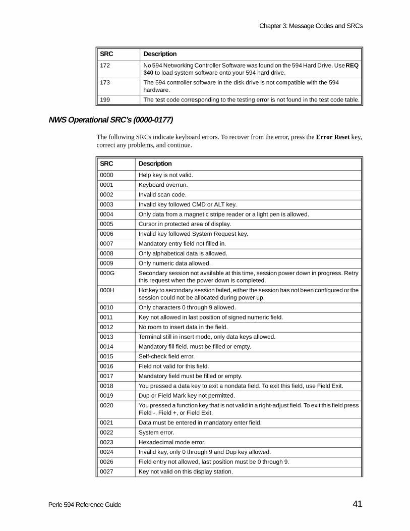
Chapter 3: Message Codes and SRCs
NWS Operational SRC’s (0000-0177)
The following SRCs indicate keyboard errors. To recover from the error, press the Error Reset key,correct any problems, and continue.
172 No 594 Networking Controller Software was found on the 594 Hard Drive. Use REQ 340 to load system software onto your 594 hard drive.
173 The 594 controller software in the disk drive is not compatible with the 594 hardware.
199 The test code corresponding to the testing error is not found in the test code table.
SRC Descri ption
0000 Help key is not valid.
0001 Keyboard overrun.
0002 Invalid scan code.
0003 Invalid key followed CMD or ALT key.
0004 Only data from a magnetic stripe reader or a light pen is allowed.
0005 Cursor in protected area of display.
0006 Invalid key followed System Request key.
0007 Mandatory entry field not filled in.
0008 Only alphabetical data is allowed.
0009 Only numeric data allowed.
000G Secondary session not available at this time, session power down in progress. Retry this request when the power down is completed.
000H Hot key to secondary session failed, either the session has not been configured or the session could not be allocated during power up.
0010 Only characters 0 through 9 allowed.
0011 Key not allowed in last position of signed numeric field.
0012 No room to insert data in the field.
0013 Terminal still in insert mode, only data keys allowed.
0014 Mandatory fill field, must be filled or empty.
0015 Self-check field error.
0016 Field not valid for this field.
0017 Mandatory field must be filled or empty.
0018 You pressed a data key to exit a nondata field. To exit this field, use Field Exit.
0019 Dup or Field Mark key not permitted.
0020 You pressed a function key that is not valid in a right-adjust field. To exit this field press Field -, Field +, or Field Exit.
0021 Data must be entered in mandatory enter field.
0022 System error.
0023 Hexadecimal mode error.
0024 Invalid key, only 0 through 9 and Dup key allowed.
0026 Field entry not allowed, last position must be 0 through 9.
0027 Key not valid on this display station.
SRC Descri ption
Perle 594 Reference Guide 41

Chapter 3: Message Codes and SRCs
0028 Key not valid on this display station.
0029 Diacritic character not valid.
0031 Data buffer overflow.
0032 Magnetic stripe reader, invalid data.
0033 Magnetic stripe reader, data not authorized.
0034 Magnetic stripe reader, data exceeds field length.
0035 Magnetic stripe reader, card cannot be read.
0036 Cursor select not allowed in field exit mode.
0037 Cursor select not allowed in a nonselectable field.
0038 Magnetic stripe reader or light pen not allowed for this field.
0040 Modem or DCE Not Ready.Data Set Ready (DSR) Line Inactive for V.24 or V.35, or DCE Not Ready for X.21.This error indicates that the modem or DCE was not ready during required intervals of normal operation. The operating state of the modem or DCE is checked at different times, depending on the specific link-level protocol in use.
0041 The receive line was idle for at least 15 bit times. Verify all cable and line connections. If the problem persists, contact the network administrator.
0042 The receive clock signal from the modem or DCE is not being received. Verify all cable and line connections. If the problem persists, contact the network administrator.
0043 The data set ready (DSR) signal was not deactivated by the modem or DCE even though the 594 tried to disconnect from the line. Verify all cable and line connections. If the problem persists, contact the network administrator.
0044 30-Second Timeout.For a synchronous connection this error indicates that no valid data has been received for 30 seconds. For a LAN connection this error indicates the Ti timer has expired before a valid frame was received by the Perle 594.
0045 During link setup, either a disconnect mode (DM) or disconnect (DISC) command was received; the DCE will not active. Verify all cable and line connections. If the problem persists, contact the network administrator.
0046 Frame reject received. The Perle 594 received a FRMB from the network. Verify all cable and line connections. If the problem persists, contact the network administrator.
0047 The Perle 594 received an unexpected disconnect mode or disconnect command. Verify all cable and line connections. If the problem persists, contact the network administrator.
0048 An unexpected Unnumbered Acknowledgment (UA) frame was received. Verify all cable and line connections. If the problem persists, contact the network administrator.
0049 The Perle 594 received an unexpected SABME. Restart communication, if the problem persists, contact the network administrator.
0050 An error was detected in the Ready For Sending (RFS) or Clear To Send (CTS) signal. Verify all cable and line connections. If the problem persists, contact the network administrator.
0051 The transmit clock failed during a transmit operation. If the problem persists, contact the network administrator.
0052 No transmit clock, modem, or DCE signal was detected even though the link adapter did not complete a transmit operation within the allotted time period. Verify all cable and line connections. If the problem persists, contact the network administrator.
SRC Description
42 Perle 594 Reference Guide

Chapter 3: Message Codes and SRCs
0053 Expiration of Retry Counter (X.25 only).No acknowledgment of a transmission was received within the allowed timeout. (Timeout retry counter (N2) and retry interval (T1) are specified in Field 7 of the NWS configurator.)
0054 Frame reject sent. The Perle 594 has sent a FRMR response to the AS/400 system after receiving an invalid DLC or LAPB command.
0055 The Perle 594 has determined that the communication cable is not attached to the 594. Attach a cable to the 594 or replace the one currently attached.
0056 Link was broken between the Perle 594 and the host. Ensure that delays and timer values are sufficiently long. If the problem persists, contact the network administrator.
0060 Alphanumeric character entered into double-byte data characters or a key that is invalid within an embedded segment was pressed.
0061 Double-byte character entered into an alpha numeric field or a key that is invalid outside an embedded segment was pressed.
0062 Change data type not allowed, the cursor must be in an open field or in the first position ideographic field.
0063 Invalid ideographic character entered while in alternate entry mode.
0064 Invalid key pressed for the current keyboard mode.
0065 Invalid cursor position, column reserved for shift-out or shift-in characters.
0066 Repeat key not valid at current position.
0067 Workstation extension character RAM is full. Therefore, additional extension characters will be displayed as default characters.
0068 Perle 594 output data stream is not valid for extension characters. Therefore, any additional extension characters will be displayed as default characters.
0069 Perle 594 output data stream contains invalid or undefined extension characters. Additional extension characters will be displayed as default characters.
006G Invalid terminal type. A double byte character terminal is attached to a Twinaxial Feature Card with Card ID 41. A card with Card ID 44 must be used.
0070 Word spill or carrier return error.
0071 Invalid start copy, move, or delete text operation while a previous operation is still in progress.
0072 Invalid key pressed for the current cursor position.
0073 Invalid instruction attempted while the general prompt function was not active.
0074 Invalid key pressed while the general prompt function is active.
0075 Keyed characters not found.
0076 Insert function failed, the AS/400 has not processed the text on the screen.
0077 Invalid function key pressed or a 3270 keyboard function was entered while in word processing mode.
0078 Application error, the required scale line is not defined for your workstation.
0081 Configuration error, there are too many devices attached.
0082 Invalid keyboard function.
0083 Invalid selection.
0084 Selection field unavailable.
0087 Flow control error. Be sure X.25 communication settings on the Perle 594 match X.25 communication worksheet.
0089 One or more required fields not complete.
SRC Description
Perle 594 Reference Guide 43
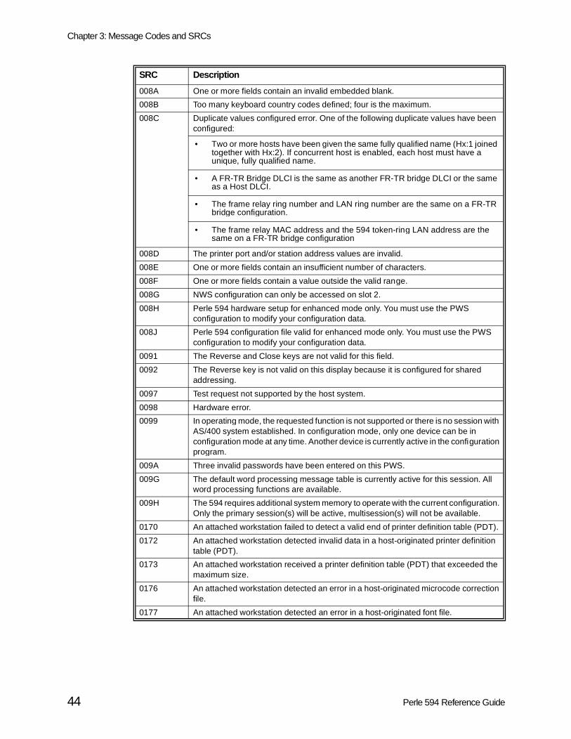
Chapter 3: Message Codes and SRCs
008A One or more fields contain an invalid embedded blank.
008B Too many keyboard country codes defined; four is the maximum.
008C Duplicate values configured error. One of the following duplicate values have been configured:
• Two or more hosts have been given the same fully qualified name (Hx:1 joined together with Hx:2). If concurrent host is enabled, each host must have a unique, fully qualified name.
• A FR-TR Bridge DLCI is the same as another FR-TR bridge DLCI or the same as a Host DLCI.
• The frame relay ring number and LAN ring number are the same on a FR-TR bridge configuration.
• The frame relay MAC address and the 594 token-ring LAN address are the same on a FR-TR bridge configuration
008D The printer port and/or station address values are invalid.
008E One or more fields contain an insufficient number of characters.
008F One or more fields contain a value outside the valid range.
008G NWS configuration can only be accessed on slot 2.
008H Perle 594 hardware setup for enhanced mode only. You must use the PWS configuration to modify your configuration data.
008J Perle 594 configuration file valid for enhanced mode only. You must use the PWS configuration to modify your configuration data.
0091 The Reverse and Close keys are not valid for this field.
0092 The Reverse key is not valid on this display because it is configured for shared addressing.
0097 Test request not supported by the host system.
0098 Hardware error.
0099 In operating mode, the requested function is not supported or there is no session with AS/400 system established. In configuration mode, only one device can be in configuration mode at any time. Another device is currently active in the configuration program.
009A Three invalid passwords have been entered on this PWS.
009G The default word processing message table is currently active for this session. All word processing functions are available.
009H The 594 requires additional system memory to operate with the current configuration. Only the primary session(s) will be active, multisession(s) will not be available.
0170 An attached workstation failed to detect a valid end of printer definition table (PDT).
0172 An attached workstation detected invalid data in a host-originated printer definition table (PDT).
0173 An attached workstation received a printer definition table (PDT) that exceeded the maximum size.
0176 An attached workstation detected an error in a host-originated microcode correction file.
0177 An attached workstation detected an error in a host-originated font file.
SRC Description
44 Perle 594 Reference Guide

Chapter 3: Message Codes and SRCs
mand,
S/400 to that
X.25 Communication SRC’s (100000-1BFF00)
If you are using X.25 communication and an error occurs during the keyboard entry of a comoption or parameter, a 6-digit SRC between 100000 and 10FFFF is displayed.
If the controller accepts the keyboard-entered options but the network operation with the Asystem fails, an SRC between 110000-1BFF00 is displayed on all display stations attachedcontroller. These SRCs indicate a communication network problem at the packet level.
SRC Description
100000 Previous X.25 command still being executed.
100100 A virtual circuit has already been established. The Perle 594 can only communicate over one virtual circuit per controller at a time.
100200 An answer command was entered for a PVC circuit. A PVC circuit requires an open command.
100300 A call command was entered for a PVC circuit. A PVC circuit requires an open command.
100400 The logical channel ID is not valid because it is not three characters long.
100500 The logical channel ID option is not valid because it is not a hexadecimal value between 001 and FFF.
100600 The password option is not valid because it is longer than eight characters or contains nonalphanumeric characters.
100700 The host network address is not valid because it is longer than 15 decimal digits or contains nonnumeric characters.
100A00 The operator attempted to enter option fields not supported by that connection type.
100B00 The X.25 facility entered contains invalid characters.
100C00 The X.25 packet window size entered is invalid because it is less than 02.
100D00 The X.25 packet window size entered is invalid because modulo 8 is specified and the packet size is greater than 07.
100E00 The X.25 packet window size entered is invalid because modulo 128 is specified and the packet size is greater than 15.
100F00 The X.25 packet size is not equal to 64, 128, 256, or 512.
101000 The X.25 closed user group option does not contain 2 decimal digits.
101100 An invalid control character was entered.
101300 For X.25: Either a) the first control character entered was not one of A, O, C, or D or b) the first control character has already been entered.
101500 The password option was entered for a PVC.
101600 The X.25 password is invalid because it contains characters that are not alphanumeric.
101800 The X.25 closed user group option was entered for a command that was not a CALL command issued on an SVC.
101900 The option Q (QLLC) or E (ELLC) is not valid with an answer command. Use these options with an SVC call or PVC open command.
101A00 The X.25 F or R option was entered for a command that was not initiating a CALL command on an SVC.
101B00 The recovery value for the E (ELLC) option must be from 100 to 199.
101C00 A CALL command was entered for an answer-only SVC. The 594 configuration may be incorrect.
101D00 An open command was entered for a manual connect SVC controller.
Perle 594 Reference Guide 45

Chapter 3: Message Codes and SRCs
SRCs 110000—1100FF
The controller issued a clear request packet after detecting an error.
SRC Description
110000 No additional information.Report the problem to your AS/400 system operator.
110014 The Perle 594 received an X.25 packet type that is invalid for state p1 and issued a Clear Request.
110015 The Perle 594 detected an X.25 packet type that is invalid for state p2 and issued a Clear Request.
110017 The Perle 594 detected an X.25 packet type that is invalid for state p4 and issued a Clear Request.
110018 The Perle 594 detected an X.25 packet type that is invalid for state p5 and issued a Clear Request.
110031 The Perle 594 issued an X.25 Clear Request because a Call Connected was not received within 200 seconds. Contact the X.25 network service provider.
110032 The Perle 594 issued an X.25 Clear Request because a Clear Confirmation was not received within 200 seconds. Contact the X.25 network service provider.
110046 Call from unexpected DTE.Verify the network address and retry. If the problem continues, report the problem to your AS/400 system operator.
110050 A general ELLC/QLLC error has occurred. Report the problem to the AS/400 system operator.
110051 An undefined ELLC C field was detected. Report the problem to the AS/400 system operator.
110054 An undefined ELLC I field was detected. Report the problem to the AS/400 system operator.
110055 An I field that was longer than the allowed 521 bytes was detected. Report the problem to the AS/400 system operator.
110056 An error occurred and an ELLC frame reject was received. Report the problem to the AS/400 system operator.
110057 An invalid ELLC header was detected. Report the problem to the AS/400 system operator.
110059 An ELLC timeout condition was detected. Report the problem to the AS/400 system operator.
11005A An invalid ELLC receive sequence count was detected. Report the problem to the AS/400 system operator.
11005B An ELLC recovery was rejected or terminated.
1100A1 The Perle 594 detected an invalid X.25 M-bit packet sequence and, therefore, issued a Clear Request. Be sure the packet size entered matches the packet size specified in the network subscription.
1100A6 The Perle 594 detected an X.25 packet that was too short and, therefore, issued a Clear Request. Be sure the packet size entered matches the packet size specified in the network subscription.
1100A7 The Perle 594 detected an X.25 packet that was too long and, therefore, issued a Clear Request. Be sure the packet size entered matches the packet size specified in the network subscription.
1100AA The Perle 594 detected an unsupported, X.25 interrupt packet and, therefore, issued a Clear Request. Contact the X.25 network service provider.
46 Perle 594 Reference Guide

Chapter 3: Message Codes and SRCs
1100AB The Perle 594 detected an invalid X.25 packet send sequence number (Ps) and, therefore, issued a Clear Request. Contact the X.25 network service provider.
1100AC The Perle 594 detected an invalid X.25 packet receive sequence number (Pr) and, therefore, issued a Clear Request. Contact the X.25 network service provider.
1100AD The Perle 594 received an invalid X.25 D-bit and, therefore, issued a Clear Request. Report the problem to the AS/400 system operator.
1100D0 The Perle 594 received an X.25 general resources error and, therefore, issued a Clear Request. Report the problem to the AS/400 system operator.
1100D2 The Perle 594 received an X.25 path information (PIU) that was too long and, therefore, issued a Clear Request. Report the problem to the AS/400 system operator.
1100E0 An invalid facility length was detected. Report the problem to the AS/400 system operator.
1100E6 Unsupported facility parameters were detected. Report the problem to the AS/400 system operator.
1100E7 An unsupported facility was detected. Report the problem to the AS/400 system operator.
1100E8 A call from an unexpected DTE was detected. Retry the operation.
1100E9 The Perle 594 detected an invalid X.25 D-bit and, therefore, issued a Clear Request. Report the problem to the AS/400 system operator.
1100EA An error was detected, and there was a reset indication on an SVC.
1100EB An invalid protocol identifier was detected. Retry the operation.
1100EC A password mismatch was detected. Retry the password.
1100F4 Connection rejection, reason unspecified (transient condition).Retry the operation. Report the problem to your AS/400 system operator.
1100F5 Connection rejection, reason unspecified (permanent condition).Retry the operation. You should report the problem to your AS/400 system operator.
1100F6 Connection rejection, requested quality of service not available (transient condition).Verify your configuration. If the problem continues, report the problem to your network representative.
1100F8 Connection rejection, incompatible information in user data.Verify your configuration. If the problem continues, report the problem to your network representative.
SRC Description
Perle 594 Reference Guide 47

Chapter 3: Message Codes and SRCs
SRCs 120000—1200FF
The controller issued a reset request packet after detecting an error.
SRC Description
120000 No additional information.Report the problem to your AS/400 system operator.
120001 Invalid packet sent sequence number (Ps).Report the error to your network representative.
120002 Invalid packet received sequence number (Pr).Report the error to your network representative.
12001B Invalid packet type for state d1.Retry the operation. You may be allowed temporary operation. However, you should report the error to your network representative.
120020 Packet not allowed.Report the problem to your AS/400 system operator.
120026 Packet too short.Make sure that the packet size entered in the configuration or entered manually matches your network subscription.
120027 Packet too long.Make sure that the packet size entered in the configuration or entered manually matches your network subscription.
120033 Reset confirmation not received within 200 seconds.Report the problem to the AS/400 system operator.
120050 A general ELLC/QLLC error has occurred. Report the problem to the AS/400 system operator.
120051 An undefined ELLC C field was detected. Report the problem to the AS/400 system operator.
120054 An undefined ELLC I field was detected. Report the problem to the AS/400 system operator.
120055 An Ifield that was longer than the allowed 521 bytes was detected. Report the problem to the AS/400 system operator.
120056 An error occurred and an ELLC frame reject was received. Report the problem to the AS/400 system operator.
120057 An invalid ELLC header was detected. Report the problem to the AS/400 system operator.
120059 An ELLC timeout condition was detected. Report the problem to the AS/400 system operator.
12005A An invalid ELLC receive sequence count was detected. Report the problem to the AS/400 system operator.
12005B An ELLC recovery was rejected or terminated.
1200A1 The Perle 594 detected an invalid X.25 M-bit packet and, therefore, issued a Reset Request. Ensure packet size entered matches packet size in network subscription.
1200A6 The Perle 594 detected an X.25 packet that was too short and, therefore, issued a Reset Request. Ensure packet size entered matches packet size in network subscription.
1200A7 The Perle 594 detected an X.25 packet that was too long and, therefore, issued a Reset Request. Ensure packet size entered matches packet size in network subscription.
48 Perle 594 Reference Guide

Chapter 3: Message Codes and SRCs
rk to
SRCs 1800zz -18FFzz
The DCE issued a clear indication packet after detecting an error.
Note : Most diagnostic codes (zz) are issued by the network and may vary from netwonetwork. The diagnostic codes (zz) are defined later in this section.
1200AA The Perle 594 detected an X.25 unsupported interrupt packet and, therefore, issued a Reset Request. Contact the network service provider.
1200AB The Perle 594 detected an invalid X.25 packet send sequence number (Ps) and, therefore, issued a Reset Request. Contact the network service provider.
1200AC The Perle 594 detected an invalid X.25 packet receive sequence number (Pr) and, therefore, issued a Reset Request. Contact the network service provider.
1200AD The Perle 594 detected an invalid X.25 D-bit and, therefore, issued a Reset Request. Report the problem to the AS/400 system operator.
1200D0 The Perle 594 detected an X.25 general resources error and, therefore, issued a Reset Request. Report the problem to the AS/400 system operator.
1200D2 The Perle 594 detected anX.25 path information unit (PIU) that was too long and, therefore, issued a Reset Request. Report the problem to the AS/400 system operator.
1200F4 General resources.Retry the operation. Other applications may operate normally. However, you should report the error to your AS/400 system operator.
1200F5 PIU too long.Retry the operation. Other applications may operate normally. However, you should report the error to your AS/400 system operator.
SRC Description
1800zz Call clearing originated at AS/400 system.Report the problem to the AS/400 system operator.
1801zz AS/400 system busy.Wait, then retry the operation.
1803zz Invalid facility request.Verify the request. Report the problem to your network representative.
1805zz Network congestion.Retry the operation. If the problem continues, report the problem to your network representative.
1809zz Out of order. AS/400 system not ready.Wait, then retry the operation. If the problem continues, report the problem to your network representative.
180Bzz Access to the AS/400 system not allowed.Verify the request. Report the problem to your AS/400 system operator.
180Dzz Unrecognized AS/400 system network address.Verify the request. Report the problem to your AS/400 system operator.
1811zz Error at the AS/400 system.Report the problem to your AS/400 system operator.
1813zz Error at the Perle 594 controller.Verify the request. Report the problem to your network representative.
1815zz Recognized private operating agency (RPOA) out of order.Verify the request. Report the problem to your network representative.
SRC Description
Perle 594 Reference Guide 49

Chapter 3: Message Codes and SRCs
1819zz Reverse charging not subscribed.Verify the request. Report the problem to your network representative.
1821zz Incompatible destination.Verify the request. Report the problem to your network representative.
1829zz Fast select not supported.Verify the request.
1841zz Gateway-detected procedure error. Repeat the operation. Report the problem to the network representative.
1843zz Gateway congestion error. Repeat the operation. Report the problem to the network representative.
1880xx Call clearing originated at target X.25 DTE. Report the problem to the system operator.
1881zz Target X.25 DTE is busy. Verify the call. Report the problem to the system operator.
1883zz Invalid facility request. Verify the facility. Report the problem to the network representative.
1885zz Network is congested. Repeat the operation. Report the problem to the network representative.
1889zz Target X.25 DTE is not ready. Verify the call. Report the problem to the system operator.
188Bzz Access to selected target X.25 DTE denied. Verify the link and configuration. Report the problem to the system operator.
188Dzz Target X.25 DTE network address is not recognized. Verify the address. Report the problem to the system operator.
1891zz Error at target X.25 DTE. Report the problem to the system operator.
1893zz Error at the Perle 594.
1895zz Recognized private operating agency (RPOA) is out of order. Verify the RPOA. Report the problem to the network representative.
1899zz Reverse charging not subscribed to. Report problem to the network representative.
18A1zz Incompatible destination. Verify the link and address. Report the problem to the network representative.
18A9zz Fast select not subscribed to. Verify the link.
18C1zz Gateway-detected procedure error. Wait and retry the operation. Report the problem to the network representative and the system operator.
18C3zz Gateway congestion error. Wait and retry the operation. Report the problem to the network representative and the system operator.
SRC Description
50 Perle 594 Reference Guide
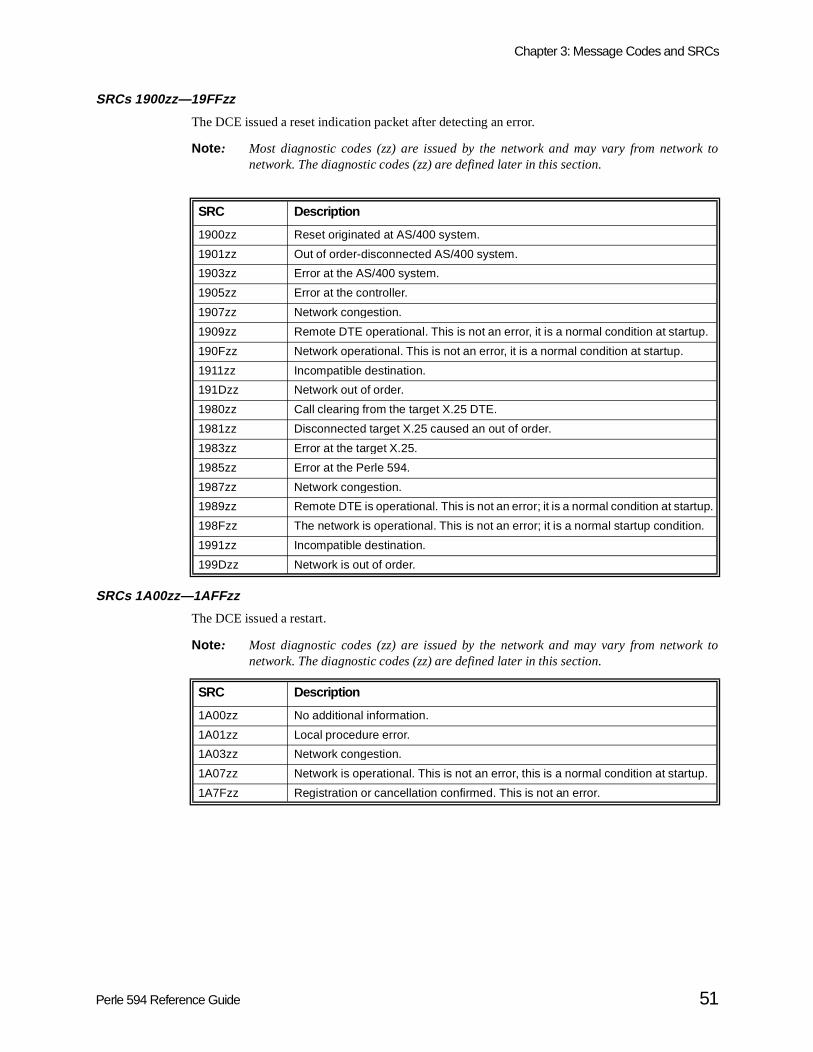
Chapter 3: Message Codes and SRCs
rk to
rk to
SRCs 1900zz—19FFzz
The DCE issued a reset indication packet after detecting an error.
Note : Most diagnostic codes (zz) are issued by the network and may vary from netwonetwork. The diagnostic codes (zz) are defined later in this section.
SRCs 1A00zz—1AFFzz
The DCE issued a restart.
Note : Most diagnostic codes (zz) are issued by the network and may vary from netwonetwork. The diagnostic codes (zz) are defined later in this section.
SRC Description
1900zz Reset originated at AS/400 system.
1901zz Out of order-disconnected AS/400 system.
1903zz Error at the AS/400 system.
1905zz Error at the controller.
1907zz Network congestion.
1909zz Remote DTE operational. This is not an error, it is a normal condition at startup.
190Fzz Network operational. This is not an error, it is a normal condition at startup.
1911zz Incompatible destination.
191Dzz Network out of order.
1980zz Call clearing from the target X.25 DTE.
1981zz Disconnected target X.25 caused an out of order.
1983zz Error at the target X.25.
1985zz Error at the Perle 594.
1987zz Network congestion.
1989zz Remote DTE is operational. This is not an error; it is a normal condition at startup.
198Fzz The network is operational. This is not an error; it is a normal startup condition.
1991zz Incompatible destination.
199Dzz Network is out of order.
SRC Description
1A00zz No additional information.
1A01zz Local procedure error.
1A03zz Network congestion.
1A07zz Network is operational. This is not an error, this is a normal condition at startup.
1A7Fzz Registration or cancellation confirmed. This is not an error.
Perle 594 Reference Guide 51

Chapter 3: Message Codes and SRCs
18yyzz—1Ayyzz (zz) Diagnostic Codes
The following are the diagnostic codes (zz) for 18yyzz, 19yyzz, and 1Ayyzz:
Diagnostic Code (zz)
Description
00 No additional information.
01 Send sequence P (s) not valid.
02 Received sequence P (r) not valid.
10 Packet type not valid.
11 State r1.
12 State r2.
13 State r3.
14 State p1.
15 State p2.
16 State p3.
17 State p4.
18 State p5.
19 State p6.
1A State p7.
1B State d1.
1C State d2.
1D State d3.
20 Packet not allowed.
21 Unidentifiable packet.
22 Call on oneway logical channel.
23 Invalid packet type on a permanent virtual circuit.
24 Packet on unassigned logical circuit.
25 Reject not subscribed to.
26 Packet too short.
27 Packet too long.
28 Invalid general format identifier.
29 Restart with LCID not equal to hexadecimal 000.
2A Packet type not compatible with facility.
2B Unauthorized interrupt confirmation.
2C Unauthorized interrupt.
2D Unauthorized reject.
30 Timer expired, general.
31 Timer expired for incoming call.
32 Timer expired for clear indication packet.
33 Timer expired for reset indication packet.
34 Timer expired for restart indication packet.
40 Call setup or call clearing problem.
41 Facility code not allowed.
42 Facility parameter not allowed.
52 Perle 594 Reference Guide

Chapter 3: Message Codes and SRCs
43 Invalid called address.
44 Invalid calling address.
45 Invalid facility/registration length.
46 Incoming call barred.
47 No logical channel available.
48 Call collision.
49 Duplicate facility requested.
4A Nonzero facility address.
4B Nonzero facility length.
4C Facility not provided when expected.
4D Invalid CCITTspecified DTE facility.
50 Miscellaneous problems.
51 Improper cause code from DTE.
52 Octet not aligned.
53 Inconsistent Q bit setting.
70 International problem.
71 Remote network problem.
72 International protocol problem.
73 International link out of order.
74 International link busy.
75 Transit network facility problem.
76 Remote network facility problem.
77 International routing problem.
78 Temporary routing problem.
79 Unknown called DNIC.
7A Maintenance action.
80-FF Network-specific diagnostic information.
Diagnostic Code (zz)
Description
Perle 594 Reference Guide 53

Chapter 3: Message Codes and SRCs
rk to
S/400ll the
twork.
tempts
SRCs 1B0000—1BFF00
The controller issued a restart request packet after detecting an error.
Note : Most diagnostic codes (zz) are issued by the network and may vary from netwonetwork. The diagnostic codes (zz) are defined earlier in this section.
X.21 Switched Communication SRCs (200000-250300)
If the controller accepts the keyboard entered options but the network operation with the Asystem fails, an SRC indicating the type of communication problem code is displayed on adisplay stations attached to that controller.
The 200000 through 25FFFF SRCs occur when a call progress signal is received from the ne
Contact your network supplier to determine the time period you must wait between recovery atand the maximum number of retries allowed by your network.
SRC Description
1B1100 Unsolicited restart confirmation received.
1B2400 LCID=0 nonrestart/diagnostic packet.
1B2800 Invalid GFI (restart indication/confirmation only).
1B2900 LCID is not equal to 0 on restart indication/confirmation.
1B3400 Restart confirmation packet not received within 200 seconds.
1BA5yy Diagnostic packet was received.
1BA500 Diagnostic packet received.
1BA600 Packet is too short.
1BA700 Packet is too long.
1BA800 General format identifier (GFI), restart indication, or confirmation not valid.
1BE200 Restart indication/confirmation packet logical channel identifier (LCID) is not equal to 0.
1BE500 Non-restart/diagnostic packet logical channel identifier (LCID) is equal to 0.
SRC Description
200000 A call command is already in progress. Wait until call is completed or a different SRC is displayed.
200100 Detach command accepted, call clearing in progress.
200200 Detach command attempted while a call command in progress or no circuit established.
210100 The incoming call was received by the AS/400 system. Communication should be established shortly.Wait 1 minute or until a different SRC is displayed. This status is temporary.
210200 The call is being redirected to a number other than the one entered.Wait 1 minute or until a different SRC is displayed. This status is temporary.
210300 The call was queued, and communication will be established when the AS/400 system is not busy.Wait 1 minute or until a different SRC is displayed. This status is temporary.
210400 A private network was reached.Wait 1 minute or until a different SRC is displayed. This status is temporary.
54 Perle 594 Reference Guide

Chapter 3: Message Codes and SRCs
210500 A public network was reached.Wait 1 minute or until a different SRC is displayed. This status is temporary.
212000 There is no connection.Make sure that the number called is correct, and try the operation again. This is a DCE or a network error.
212100 The number is busy.Make sure that the number called is correct, and try the operation again. If the number is busy for longer than normal, call the AS/400 system operator to see if the system port for the number dialed is actually busy. If the number is correct and the port is not busy, this is a network problem.
212200 There is a procedure error in the selection signals sent to the network.Make sure that the operating procedures are correct, and try the operation again. If the same failure occurs, the problem is caused by the DCE or the network.
212300 The network detected a transmission error in the selection signals.Make sure that the number called is correct, and try the operation again. This is a DCE or a network error.
214100 Access is barred.Make sure that the number called is correct and that the operating procedures and configuration are compatible with the network subscription for the controller and the AS/400 system location. If the number, the procedures, and configuration are correct and compatible, the failure is a network problem.
214200 The number you are calling has changed.Make sure that the number called is correct and that the operating procedures and configuration are compatible with the network subscription for the controller and the AS/400 system location. If the number, the procedures, and configuration are correct and compatible, the failure is a network problem.
214300 The called DTE address is not valid or not assigned to any DTE, or the user class of service is not compatible.Make sure that the number called is correct and that the operating procedures and configuration are compatible with the network subscription for the controller and the AS/400 system location. If the number, the procedures, and configuration are correct and compatible, the failure is a network problem.
214400 The number you called is out of order.Make sure that the number called is correct, that the AS/400 system you called as well as the DCE are on and ready, and that the controller is brought online by the AS/400 system operator. If the AS/400 system and DCE are on and ready and the controller is online, the failure is a network problem.
214500 The called DTE is signaling controlled-not-ready.Make sure that the number called is correct, that the AS/400 system you called as well as the DCE are on and ready, and that the controller is brought online by the AS/400 system operator. If the AS/400 system and DCE are on and ready and the controller is online, the failure is a network problem.
214600 The called DTE is signaling uncontrolled-not-ready.Make sure that the number called is correct, that the AS/400 system you called as well as the DCE are on and ready, and that the controller is brought online by the AS/400 system operator. If the AS/400 system and DCE are on and ready and the controller is online, the failure is a network problem.
214700 The called DCE is powered off.Make sure that the number called is correct, that the AS/400 system you called as well as the DCE are on and ready, and that the controller is brought online by the AS/400 system operator. If the AS/400 system and DCE are on and ready and the controller is online, the failure is a network problem.
SRC Description
Perle 594 Reference Guide 55

Chapter 3: Message Codes and SRCs
214800 The facility request code is not valid.Make sure that the facility request code is correct and that the operating procedures and configuration are compatible with the network subscription for the controller and the AS/400 system location. If the code, the procedures, and configuration are correct and compatible, the failure is a network problem.
214900 There is a network problem in the local loop at the DCE you called.Make sure that the number called is correct and that the operating procedures and configuration are compatible with the network subscription for the controller and the AS/400 system location. If the number, the procedures, and configuration are correct and compatible, the failure is a network problem.
215100 The number called cannot be obtained.Make sure that the number called is correct and that the operating procedures and configuration are compatible with the network subscription for the controller and the AS/400 system location. If the number, the procedures, and configuration are correct and compatible, the failure is a network problem. Call your network supplier to find out why the number is unobtainable.
215200 The user class of service is not compatible.Make sure that the number called is correct and that the operating procedures and configuration are compatible with the network subscription for the controller and the AS/400 system location. If the number, the procedures, and configuration are correct and compatible, the failure is a network problem.
216100 The network is congested.Make sure that the number is called is correct, and try the operation again. This is a network error.
217100 There is long-term network congestion.Make sure that the number is called is correct, and try the operation again. This is a network error.
217200 The recognized private operating agency (RPOA) is out of order.The failure is caused by an RPOA problem or a network problem.
218100 The registration or cancellation is confirmed.This is a confirmation, not an error.
218200 Redirection of the call facility is activated.This is a response to a status inquiry, not an error.
218300 Redirection of the call facility is deactivated.This is a response to a status inquiry, not an error.
219x00 Codes reserved for national purposes.Your network supplier can provide you with the meaning of the call progress signal 9x.
220000 An invalid XID was received (invalid short hold indicators).Make sure that the number called was correct. There may be an AS/400 system programming error or a configuration problem.
220100 An invalid XID was received (more than 27 digits were received or the number of digits received does not equal the number of digits specified for short hold mode).Make sure that the number called was correct. There may be an AS/400 system programming error or a configuration problem.
220200 The wrong XID was received.Make sure that the number called was correct. There may be an AS/400 system programming error or a configuration problem.
220300 An XID was required and was not received first.Make sure that the number called was correct. There may be an AS/400 system programming error or a configuration problem.
SRC Description
56 Perle 594 Reference Guide

Chapter 3: Message Codes and SRCs
220400 A DCE clear was received during call selection.The failure is caused by a network or DCE problem. Report the problem to a network service representative.
220500 Invalid transition to data transfer state while message was received. Report problem to network representative.
220600 Message was too long for buffer. Report problem to network representative.
220700 Attempt was made to send an X.21 message to the network in SDLC state. Contact your Perle 594 representative.
220800 Attempt was made to send an SDLC frame to the network in X.21 state. Contact your Perle 594 representative.
220900 Message was received in the not-ready queue. Contact your Perle 594 representative.
221101 A timeout (T1) for call-request response occurred.The failure is caused by a network or DCE problem. This error can occur if the AS/400 system configuration does not match the Perle 594 configuration. Make sure that the controller is in operating mode. Report the problem to a network service representative.
221102 A timeout (T2) for selection-signal response occurred.The failure is caused by a network or DCE problem. Report the problem to a network service representative.
221103 A timeout (T3A or T3B) for call-progress-signal response occurred.The failure is caused by a network or DCE problem. Report the problem to a network service representative.
221104 A timeout (T4B) for call-accepted response occurred.The failure is caused by a network or DCE problem. Report the problem to a network service representative.
221105 A timeout (T5) for DTE-clear-request occurred.The failure is caused by a network or DCE problem. Report the problem to a network service representative.
221106 A timeout (T6) for DTE-clear-confirmation occurred.The failure is caused by a network or DCE problem. Report the problem to a network service representative.
221300 A call-collision error occurred.Try the operation again. If the error occurs again, report the problem to a network service representative.
221400 A DCE clear was received during X.21 data-transfer state. Connection to the AS/400 system was lost.Make sure that the number called is correct. If the number called is correct, there is an AS/400 system or network problem.
221500 Received Exchange Station Identifier (XID) indicated the AS/400 system was busy.
23xx00 A call progress signal (xx) was received from the network, but a call was not placed.The failure was caused by a network or DCE problem. Report the problem to a network service representative.
240000 The DTE received an invalid call progress signal.The failure is caused by a network or DCE problem. Report the problem to a network service representative.
250100 Invalid XID3 command received, no network name control vector. Contact the AS/400 system operator, there is an AS/400 configuration error.
250200 Invalid XID3 command received, no short hold mode control vector. Contact the AS/400 system operator, there is an AS/400 configuration error.
SRC Description
Perle 594 Reference Guide 57

Chapter 3: Message Codes and SRCs
Vi25 bis SRC’s (300000-323400)
250300 Invalid XID3 command received, no short hold connection ID. Contact the AS/400 system operator, there is an AS/400 configuration error.
SRC Description
300000 Call request not allowed. Wait 30 seconds and retry the call or wait until a different SRC is displayed.
300100 Disconnect command accepted.
300200 Call clearing not allowed. Do not try to clear the call.
3101ET Number is busy. Verify the call then try the call again. Contact the system operator.
3102xx Delayed Call Indication received. Wait the length of time in minutes indicated by xx. Then recall.
310300 Invalid Call Indication was received. Try call again. If needed, contact the network representative.
320100 Error occurred in message transmission. Try call again. If needed, contact Perle 594 service.
320600 Message was too long to fit in buffer. Contact Perle 594 service.
320900 Message was received in the not-ready queue. Contact Perle 594 service.
321000 Ready for Sending (RFS) timeout occurred while the link was being established. Verify the link is correct. If needed, contact the network representative.
321100 Call-connected timeout occurred for an outgoing call. Verify the link is correct. If needed, contact the network representative.
321200 Call-connected timeout occurred for an incoming call. Verify the link is correct. If needed, contact the network representative.
322000 Call-collision error occurred. Try call again. If needed, contact the network service representative.
322100 Incoming call was rejected because state of the call was invalid. Try call again. If needed, contact the network service representative.
323100 Message containing fewer than 3 characters was received. Contact service representative for the modem or the network.
323300 Invalid call-failure-indication parameter was received. Contact service representative for the modem or the network.
323400 No time was indicated for the delayed call failure indication that was received. Contact service representative for the modem or the network.
SRC Description
58 Perle 594 Reference Guide

Chapter 3: Message Codes and SRCs
SNA Communication SRC’s (400000-470200)
SRC Description
400000 Connection attempt is already in progress.
400100 Connect request was rejected. Retry call in one minute. If needed, contact service representative for the modem, DCE, or network.
400200 Data entered in the wrong format, correct the request and retry.
400300 Disconnect attempt from an unconnected AS/400, correct the request and retry.
400400 Request rejected, LU name is not configured for the selected AS/400 system. Correct the request and retry.
400500 Request rejected, command not allowed for this communication configuration. Correct the request and retry.
400600 Invalid request format, correct the request and retry.
400700 Request rejected, connection number is not configured for the selected AS/400 system. Correct the request and retry.
400800 Request rejected, the link to the AS/400 already exists.
400900 Request rejected, the Perle 594 is already establishing a link to the AS/400.
400A00 Request was rejected because:a) the 594 controller is not configured for concurrent hosts.b) an attempt was made to perform a host switch from an NWS to which multisessions were assigned. Concurrent host switches are only allowed from NWSs to which no multisessions have been assigned.
400B00 Request was rejected because link to the host is already active. Wait for a different SRC to be displayed or for a sign-on screen.
400C00 Disconnect command was rejected. Wait two minutes for a sign-on screen. Then try the operation again.
400D00 Request was rejected because no printer is powered on at the address you specified or is not being recognized by the 594.
410000 Exchange protocol error occurred for an Exchange Station Identifier (XID). Verify the configuration. If needed, contact the system operator or the network service representative.
410100 XID command length error, contact the AS/400 system operator.
410200 XID contains an unsupported I field format, contact the AS/400 system operator.
410300 XID command exchange state indicators are set to "not supported", contact AS/400 system operator.
410400 XID3 command did not specify SDLC, contact the AS/400 system operator.
410500 XID3 command specified ABM support, contact the AS/400 system operator.
410600 XID3 command specified ALS as secondary, contact the AS/400 system operator.
410700 XID3 command specified a maximum BTU length less than 256 bytes, contact the AS/400 system operator.
410800 XID3 command specified an SDLC profile that is not valid, contact the AS/400 system operator.
410900 XID3 command specified a maximum I frame outstanding value that is not valid, contact the AS/400 system operator.
411200 The AS/400 reported an error in the XID response. This may be an invalid configuration on the AS/400 of the Perle 594. Sense data contains the 3-byte error offset received in the control vector. Verify the AS/400 and the Perle 594 configuration (note CP names).
Perle 594 Reference Guide 59

Chapter 3: Message Codes and SRCs
420000 There was a timeout on completion of a change number of sessions (CNOS). Try communicating with the AS/400 system again. If needed, contact the AS/400 system operator. By examining the content of the first sense byte, you can tell which AS/400 host the 594 controller was trying to contact when the error occurred:00 = H1; 40 = H2; 80 = H3; C0 = H4.
420100 A CNOS reply contains unacceptable values, contact the AS/400 system operator.By examining the content of the first sense byte, you can tell which AS/400 host the 594 controller was trying to contact when the error occurred:00 = H1; 40 = H2; 80 = H3; C0 = H4.
420200 A CNOS reply contains a format error, contact the AS/400 system operator.By examining the content of the first sense byte, you can tell which AS/400 host the 594 controller was trying to contact when the error occurred:00 = H1; 40 = H2; 80 = H3; C0 = H4.
4203xx Abnormal CNOS reply, if xx=02 the Perle 594 mode name is not defined on the AS/400. Contact the AS/400 system operator.By examining the content of the first sense byte, you can tell which AS/400 host the 594 controller was trying to contact when the error occurred:00 = H1; 40 = H2; 80 = H3; C0 = H4.
420400 There was a timeout on completion of a change number of sessions (CNOS). Contact the AS/400 system operator.By examining the content of the first sense byte, you can tell which AS/400 host the 594 controller was trying to contact when the error occurred:00 = H1; 40 = H2; 80 = H3; C0 = H4.
421000 There was a negative response to the change number of sessions (CNOS) BIND. Try communicating with the AS/400 system again. If needed, contact the AS/400 system operator.By examining the content of the first sense byte, you can tell which AS/400 host the 594 controller was trying to contact when the error occurred:00 = H1; 40 = H2; 80 = H3; C0 = H4.
4211xx The Perle 594 received an unbind (type xx), try to re-establish communication, if unsuccessful contact the AS/400 system operator.By examining the content of the first sense byte, you can tell which AS/400 host the 594 controller was trying to contact when the error occurred:00 = H1; 40 = H2; 80 = H3; C0 = H4.
421200 Error detected in the LU6.2 CNOS session. The Perle 594 received a function management header indicating session termination. Verify configuration, if problem persists contact the AS/400 system operator.By examining the content of the first sense byte, you can tell which AS/400 host the 594 controller was trying to contact when the error occurred:00 = H1; 40 = H2; 80 = H3; C0 = H4.
421300 An error occurred while the change number of sessions (CNOS) between the 594 and the AS/400 system was being established or was in progress. Verify the configuration. Then try to reconnect. If needed, contact the AS/400 system operator.By examining the content of the first sense byte, you can tell which AS/400 host the 594 controller was trying to contact when the error occurred:00 = H1; 40 = H2; 80 = H3; C0 = H4.
4221xx The Perle 594 sent an xx type unbind to the AS/400. Verify configuration, if problem persists contact the AS/400 system operator.By examining the content of the first sense byte, you can tell which AS/400 host the 594 controller was trying to contact when the error occurred:00 = H1; 40 = H2; 80 = H3; C0 = H4.
SRC Description
60 Perle 594 Reference Guide

Chapter 3: Message Codes and SRCs
430000 An error occurred while the LU 6.2 session between the 594 and the AS/400 system was being established or was in progress. Try to reconnect. If needed, contact the AS/400 system operator.By examining the content of the first sense byte, you can tell which AS/400 host the 594 controller was trying to contact when the error occurred:00 = H1; 40 = H2; 80 = H3; C0 = H4.
430001 An error occurred while the LU 6.2 session between the 594 and the AS/400 system was being established or was in progress. Contact the AS/400 system operator.By examining the content of the first sense byte, you can tell which AS/400 host the 594 controller was trying to contact when the error occurred:00 = H1; 40 = H2; 80 = H3; C0 = H4.
431000 The Perle 594 received a negative response to a bind command. Verify configuration, if problem persists contact the AS/400 system operator.By examining the content of the first sense byte, you can tell which AS/400 host the 594 controller was trying to contact when the error occurred:00 = H1; 40 = H2; 80 = H3; C0 = H4.
4311xx Error detected in the LU6.2 session. The Perle 594 received an UNBIND type xx. Verify configuration, if problem persists contact the AS/400 system operator.By examining the content of the first sense byte, you can tell which AS/400 host the 594 controller was trying to contact when the error occurred:00 = H1; 40 = H2; 80 = H3; C0 = H4.
431200 Error detected in the LU6.2 session. The Perle 594 received a function management header indicating session termination. Verify configuration, if problem persists contact the AS/400 system operator.By examining the content of the first sense byte, you can tell which AS/400 host the 594 controller was trying to contact when the error occurred:00 = H1; 40 = H2; 80 = H3; C0 = H4.
431300 An error occurred while the LU 6.2 session between the 594 and the AS/400 system was being established or was in progress. Verify the configuration, if the AS/400 is operating. If not, wait for the connection to be established again or for a different SRC to be displayed.By examining the content of the first sense byte, you can tell which AS/400 host the 594 controller was trying to contact when the error occurred:00 = H1; 40 = H2; 80 = H3; C0 = H4.
4321xx Error detected in the LU6.2 session. The Perle 594 sent an UNBIND type xx. Verify configuration, if problem persists contact the AS/400 system operator.By examining the content of the first sense byte, you can tell which AS/400 host the 594 controller was trying to contact when the error occurred:00 = H1; 40 = H2; 80 = H3; C0 = H4.
438904 The AS/400 did not accept the Perle 594 connection request, no controller description was found. Verify the AS/400 and the Perle 594 configuration (note CP names).By examining the content of the first sense byte, you can tell which AS/400 host the 594 controller was trying to contact when the error occurred:00 = H1; 40 = H2; 80 = H3; C0 = H4.
438905 The AS/400 did not accept the 594 connection request because this 594 description was already active.By examining the content of the first sense byte, you can tell which AS/400 host the 594 controller was trying to contact when the error occurred:00 = H1; 40 = H2; 80 = H3; C0 = H4.
SRC Description
Perle 594 Reference Guide 61

Chapter 3: Message Codes and SRCs
438908 The AS/400 did not accept the 594 connection request because this 594 description has been varied offline.By examining the content of the first sense byte, you can tell which AS/400 host the 594 controller was trying to contact when the error occurred:00 = H1; 40 = H2; 80 = H3; C0 = H4.
438909 The AS/400 did not accept the 594 connection request because the 594 recovery is pending.By examining the content of the first sense byte, you can tell which AS/400 host the 594 controller was trying to contact when the error occurred:00 = H1; 40 = H2; 80 = H3; C0 = H4.
438910 The AS/400 did not accept the 594 connection request because the recovery of this 594 has been canceled.By examining the content of the first sense byte, you can tell which AS/400 host the 594 controller was trying to contact when the error occurred:00 = H1; 40 = H2; 80 = H3; C0 = H4.
438911 The AS/400 did not accept the 594 connection request because this 594 description is in a fail state.By examining the content of the first sense byte, you can tell which AS/400 host the 594 controller was trying to contact when the error occurred:00 = H1; 40 = H2; 80 = H3; C0 = H4.
438912 The AS/400 did not accept the 594 connection request because the AS/400 has an internal error.By examining the content of the first sense byte, you can tell which AS/400 host the 594 controller was trying to contact when the error occurred:00 = H1; 40 = H2; 80 = H3; C0 = H4.
439900 Invalid data was received from the AS/400 while the 594 was waiting for a response to its connection request. Contact the AS/400 system operator.By examining the content of the first sense byte, you can tell which AS/400 host the 594 controller was trying to contact when the error occurred:00 = H1; 40 = H2; 80 = H3; C0 = H4.
4411xx LU6.2 session error for an NWS. The Perle 594 received an unbind type xx, contact the AS/400 system operator.By examining the content of the first sense byte, you can find the LSID of the NWS in the low 6 bits. The identity of the AS/400 host the 594 controller was trying to contact when the error occurred is in the high 2 bits.B'00' = H1; B'01' = H2; B'10' = H3; B'11' = H4.
441200 LU6.2 session error for an NWS. The Perle 594 received an FMH7 indicating abnormal termination, contact the AS/400 system operator.By examining the content of the first sense byte, you can find the LSID of the NWS in the low 6 bits. The identity of the AS/400 host the 594 controller was trying to contact when the error occurred is in the high 2 bits.B'00' = H1; B'01' = H2; B'10' = H3; B'11' = H4.
4421xx LU6.2 session error for an NWS. The Perle 594 sent an unbind type xx, contact the AS/400 system operator.By examining the content of the first sense byte, you can find the LSID of the NWS in the low 6 bits. The identity of the AS/400 host the 594 controller was trying to contact when the error occurred is in the high 2 bits.B'00' = H1; B'01' = H2; B'10' = H3; B'11' = H4.
4500xx PWS error detected during link initialization, verify PWS configuration.xx=01 indicates bad initiate link reply (incorrect length).xx=02 indicates bad initiate link reply (nonzero return code).
4501xx PWS error detected during communication, an invalid frame was received from a PWS, verify PWS configuration, xx is the first byte of the control field.
SRC Description
62 Perle 594 Reference Guide

Chapter 3: Message Codes and SRCs
4510xx PWS error detected during XID exchange, verify PWS configuration.xx=80 frame length too long.xx=40 not a format 3 XID.xx=20 length inconsistency between XID and I/O block length.xx=10 XID exchange state not 01 or 00.xx=08 link station role was not 00.xx=04 maximum BTU acceptable to PWS was less than 109.xx=02 PWS responded to XID with neither an XID nor a disconnect.xx=01 XID frame length is too short.
4511xx PWS error detected during communication, an invalid twinaxial data link control frame was received from a PWS, verify PWS configuration, xx is the first byte of the control field.
4520xx PWS error detected during communication, the link was ended because of a severe session state conflict, verify PWS configuration.
4521xx LAN link with a PWS error detected during communication, the link was ended because of a severe session state conflict, verify PWS configuration.
4522xx PWS error detected during communication, an invalid twinaxial data link control frame was received from a PWS, verify PWS configuration, xx is the twinaxial workstation ID.
4523xx LAN link with a PWS error detected during communication, an invalid frame was received from a PWS, verify PWS configuration, xx is the LAN workstation ID.
4524xx Twinaxial data link control (TDLC) link with the PWS terminated. Turn power to the PWS off and on. Verify the PWS communication is installed and configured correctly.
4525xx LAN link with the PWS terminated. Turn power to the PWS off and on. Verify the PWS communication is installed and configured correctly.
460000 A frame was received with an invalid session address. If problem persists, contact the AS/400 system operator.
460100 A frame was received with an invalid format identification (FID) type. If problem persists contact the AS/400 system operator.
460200 A frame was received that did not contain a full transmission header (TH). If problem persists, contact the AS/400 system operator.
460300 A frame was received that did not contain a full transmission header (TH) and request header (RH). If problem persists contact the AS/400 system operator.
460400 A frame was received that did not contain a session control request code. If problem persists, contact the AS/400 system operator.
460500 The Perle 594 received an unsupported segmented frame. If problem persists contact the AS/400 system operator.
470100 An invalid BIND request was received (incorrect ODAI), contact the AS/400 system operator.
470200 An invalid BIND request was received (incorrect SIDH/SIDL), contact the AS/400 system operator.
SRC Description
Perle 594 Reference Guide 63

Chapter 3: Message Codes and SRCs
594 System Operations SRC’s (500000-520003)
SRC Description
500001 Error trying to read information from the 594 floppy diskette or 594 hard drive.
500002 Hardware cannot support parameters specified by the current configuration. Verify configuration and communication cable are correct.
500003 Perle 594 hardware is not compatible with system diskette. Replace diskette.
500004 Diskette is not a Perle 594 Controller Software Diskette.
500005 Perle 594 system diskette is write-protected.
500006 Error trying to write information to the 594 floppy diskette or 594 hard drive.
500007 Perle 594 system diskette has been superseded by a later release.
500009 Invalid value was detected in the Perle 594 configuration file. Reconfigure the 594.
50000A The attempt to download a configuration file has failed. The previous configuration file has been restored.
50000B The back up configuration file could not be found.
50000G The configuration file contains features not supported by the current version of Controller Software. Upgrade to the newest version of Controller Software or use the appropriate version of 594 Utility Program.
500011 Perle 594 is not operating in configuration mode and could not find a valid configuration file.
500013 This error indicated one of the following problems: - no AS/400 connection cable attached - faulty AS/400 connection cable attached - the communication mode configuration does not match the cable attached.
500014 The Token-Ring or Ethernet adapter is not recognized even though the 594 is configured for a LAN Gateway or a LAN AS/400 connection.
500015 Diskette error, the KTT or PDT files on the diskette are not valid. These files will be downloaded from theAS/400.
500016 A microcode error occurred. Report the SRC that appears on the front panel to your 594 service representative.
500018 Indicates the date and time the Perle 594 was restarted. This is not an error.
500019 You can only use either the Token-Ring adapter or the Ethernet adapter, depending on the configuration. If no configuration exists, the 594 will use the adapter in the lowest slot number.
50001A Indicates the configuration file was changed and the 594 will use the changed configuration file for the next installation. This is not an error.
50001C The 594 has been started with a 594 controller software that does not support one of the features currently configured in the 594 configuration file. Refer to Features of the Perle 594 in the appropriate User’s Guide.
50001D 594 has been started with a 594 Networking Controller Software Diskette with a subsequent software release level then is presently loaded on the 594 hard drive. This SRC is informational only.
50001E A SNA twinax device (NWS or PWS) has been connected to a twinax controller which has been configured as an IP Router Port with the SNA controller disabled. The SNA twinax device will not be able to communicate with the AS/400.
500040 The 594 has detected a low buffer pool condition while running a TCP/IP, FR-TR Bridge or IP Routing configuration. This SRC is informational only.
500041 The 594 has recovered from a low buffer pool shortage. This SRC is informational only.
64 Perle 594 Reference Guide

Chapter 3: Message Codes and SRCs
LAN SRC’s (540000-540425)
520000 No printer found for local copy to print function, verify printer is powered on and online.
520001 Device specified for local copy to print function is not a printer, verify configuration.
520002 Printer is busy, powered off, or in error state, correct printer condition.
520003 The Perle 594 has lost communication with the printer, correct printer condition.
SRC Description
540010 The LAN Feature Card did not initialize correctly. Power the Perle 594 OFF and ON, if problem continues contact service.
540011 Token-Ring restart in progress.
540021 The network is recovering from a beaconing condition.
540105 Command to the Ethernet or Token-Ring adapter has failed. Press the right arrow key on the Perle 594 keypad to obtain sense data. Run extended diagnostics to test all hardware.
540106 Token-Ring Gateway adapter open error. Verify the Perle 594 Token-Ring speed setting matches the LAN speed. If the problem persists, contact the Token-Ring administrator.Press the right arrow key on the Perle 594 keypad to display the sense data for this SRC:1100 lobe media function failure.2400 physical insertion ring failure, wrong speed2600 physical insertion ring failure.2700 physical insertion ring failure, ring beaconing.2A00 physical insertion error, timeout.2D00 no monitor detected.3200 address verification, signal loss.3300 unable to transmit3500 address verification, timeout.3600 address verification, ring failure.3700 address verification, ring beaconing.3800 address verification, duplicate node address.3A00 address verification, remove received.4200 ring poll, signal loss.4500 ring poll, timeout.4600 ring poll, ring failure.4700 ring poll, ring beaconing.4A00 ring poll, remove received.5500 request parameter, timeout.5600 request parameter, ring failure.5700 request parameter, ring beaconing.5900 request parameter, request.5A00 request parameter, remove received.
SRC Description
Perle 594 Reference Guide 65

Chapter 3: Message Codes and SRCs
540107 LAN Gateway frame error. Verify configuration, if problem persists, contact the LAN administrator.Press the right arrow key on the Perle 594 keypad to display the sense data for this SRC. The first byte of sense data is a cause code, the final six bytes are the AS/400 LAN address.Token-Ring cause codes:22 error in frame transmission.23 error in frame transmitted readback checking.24 unauthorized MAC frame.Ethernet cause codes:22 too many collisions
540108 Command to the Ethernet or Token-Ring adapter has failed. Press the right arrow key on the Perle 594 keypad to obtain sense data. Run extended diagnostics to test all hardware.
540109 Token-Ring Gateway XID error. Verify PWS configuration, if problem persists contact the AS/400 system operator.
540122 Token-Ring Gateway wire fault. The Perle 594 has detected a Token-Ring wire fault between the Perle 594 and the multistation access unit (MSAU). Contact the Token-Ring administrator and report that a wire fault has been detected.
540123 Token-Ring Gateway. The Perle 594 has removed itself from the network. Contact the Token-Ring administrator and report that an auto-removal command was received.
540124 Token-Ring Gateway. The Perle 594 received a remove command from the Token-Ring network. Contact the Token-Ring administrator and report that a remove command was received.
540125 Token-Ring network error, the network is beaconing due to a permanent error on the Token-Ring. Contact the Token-Ring administrator and report the condition.
5402wd There was an error during device driver initialization. The value for w indicates the error type. The value for d indicates the device driver. Press the right arrow key on the Perle 594 keypad to obtain sense data. Run extended diagnostics to test all hardware.
540404 The AS/400 did not respond to a TEST command sent from the Perle 594, contact the AS/400 system operator.
540405 The AS/400 did not respond to the XID3 command sent from the Perle 594, contact the AS/400 system operator.
SRC Description
66 Perle 594 Reference Guide

Chapter 3: Message Codes and SRCs
540406 Token-Ring adapter open error. Verify the Perle 594 Token-Ring speed setting matches the LAN speed. If the problem persists, contact the Token-Ring administrator.Press the right arrow key on the Perle 594 keypad to display the sense data for this SRC:1100 lobe media function failure2400 physical insertion ring failure, wrong speed.2600 physical insertion ring failure.2700 physical insertion ring failure, ring beaconing.2A00 physical insertion error, timeout.2D00 no monitor detected.3200 address verification, signal loss.3500 address verification, timeout.3600 address verification, ring failure.3700 address verification, ring beaconing.3800 address verification, duplicate node address.3A00 address verification, remove received.4200 ring poll, signal loss.4500 ring poll, timeout.4600 ring poll, ring failure.4700 ring poll, ring beaconing.4A00 ring poll, remove received.5500 request parameter, timeout.5600 request parameter, ring failure.5700 request parameter, ring beaconing.5900 request parameter, request.5A00 request parameter, remove receive.
540407 LAN frame error. Verify configuration, if problem persists contact the LAN administrator.Press the right arrow key on the Perle 594 keypad to display the sense data for this SRC. The first byte of sense data is a cause code, the final six bytes are the LAN address.Token-Ring cause codes:22 error in frame transmission.23 error in frame transmitted readback checking.24 unauthorized MAC frame.Ethernet cause codes:22 too may collisions
540422 The Perle 594 has detected a Token-Ring wire fault between the Perle 594 and the multistation access unit (MSAU). Contact the Token-Ring administrator and report that a wire fault has been detected.
540423 The Perle 594 has removed itself from the network. Contact the Token-Ring administrator and report that an auto-removal command was received.
540424 The Perle 594 received a remove command from the Token-Ring network. Contact the Token-Ring administrator and report that a remove command was received.
540425 Token-Ring network error, the network is beaconing due to a permanent error on the Token-Ring. Contact the Token-Ring administrator and report the condition.
SRC Description
Perle 594 Reference Guide 67

Chapter 3: Message Codes and SRCs
Frame Relay Communication SRCs (560000-560410)
SRC Description
560010 There was an initialization error with the Perle 594 host-twinaxial adapter. Run extended diagnostics to test all hardware.
560011 There is a response problem with the network's LMI. Make sure the 594's LMI matches the host/network's LMI.
560404 The ALS is not responding to the 594's TEST command. Ask the host operator to ensure the ALS is operating and is configured for the 594, and to ensure the line is varied on at the host.
560405 The ALS is not responding to the 594's XIDS command. Ask the host operator to ensure the ALS is operating, and to ensure the host system's APPC controller description and RWS controller description for your 594 are varied on.
560406 An error occurred when the Perle 594 tried to attach to the frame relay network. Run extended diagnostics to test all hardware.
560407 An error occurred when the Perle 594 tried to transmit a frame. Press the right arrow key on the Perle 594 keypad to obtain sense data. The sense data cause code is one of: 22 (frame transmission error); 23 (frame transmitted read-back checking error); 24 (medium access control frame is unauthorized). The last three digits of the sense data frame relay address are the data link connection identifier. Run extended diagnostics to test all hardware.
560408 There was a problem with a command to the Perle 594 host-twinaxial adapter. Press the right arrow key on the Perle 594 keypad to obtain sense data. Run extended diagnostics to test all hardware.
560409 The network is not reporting a configured DLCI. If the DLCI indicated in the sense data is for the correct host, make sure the configuration contains the correct DLCI for your 594. Also, this may be due to a temporary problem in the network.
560410 The network is reporting a configured DLCI as not active. If the DLCI indicated in the sense data is for the correct host, report the problem to the network service provider. Note: This can be a temporary condition caused when the network is first started up.
68 Perle 594 Reference Guide
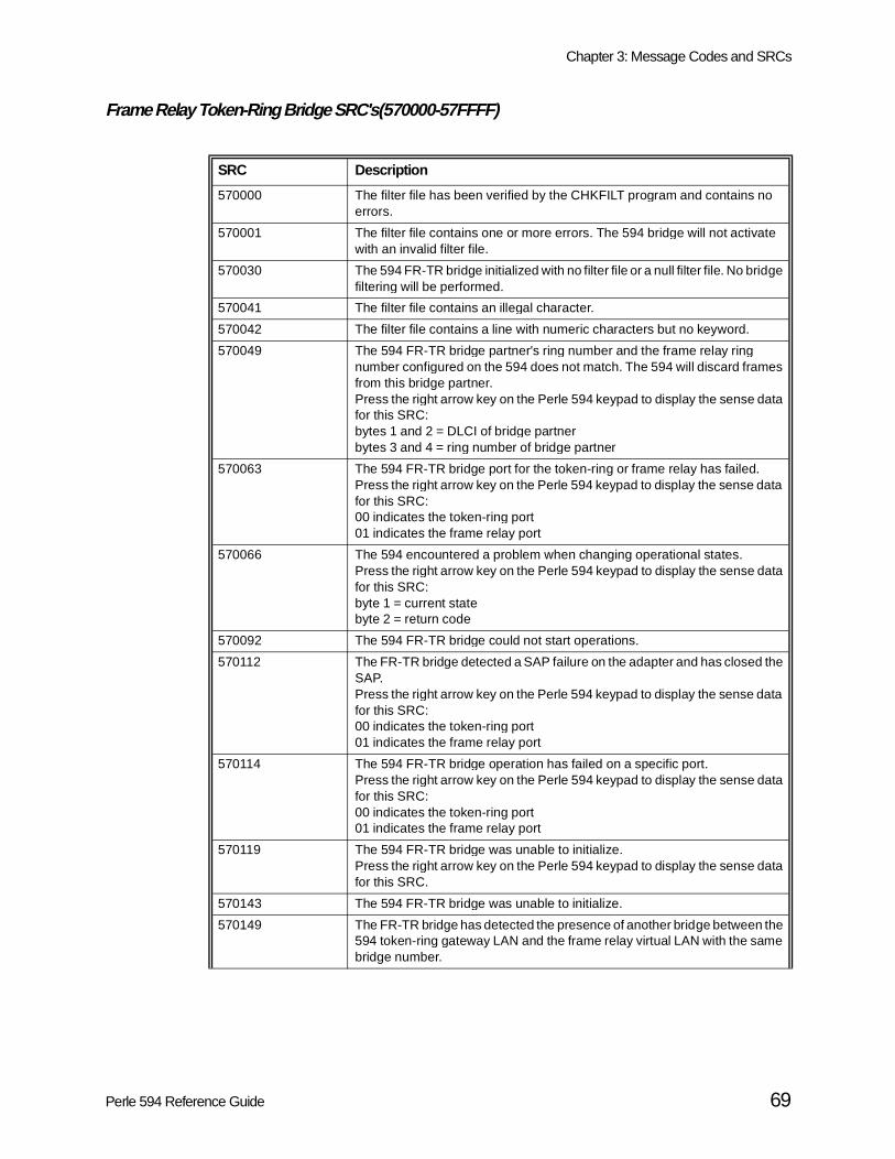
Chapter 3: Message Codes and SRCs
Frame Relay Token-Ring Bridge SRC's(570000-57FFFF)
SRC Description
570000 The filter file has been verified by the CHKFILT program and contains no errors.
570001 The filter file contains one or more errors. The 594 bridge will not activate with an invalid filter file.
570030 The 594 FR-TR bridge initialized with no filter file or a null filter file. No bridge filtering will be performed.
570041 The filter file contains an illegal character.
570042 The filter file contains a line with numeric characters but no keyword.
570049 The 594 FR-TR bridge partner's ring number and the frame relay ring number configured on the 594 does not match. The 594 will discard frames from this bridge partner.Press the right arrow key on the Perle 594 keypad to display the sense data for this SRC:bytes 1 and 2 = DLCI of bridge partnerbytes 3 and 4 = ring number of bridge partner
570063 The 594 FR-TR bridge port for the token-ring or frame relay has failed. Press the right arrow key on the Perle 594 keypad to display the sense data for this SRC:00 indicates the token-ring port 01 indicates the frame relay port
570066 The 594 encountered a problem when changing operational states.Press the right arrow key on the Perle 594 keypad to display the sense data for this SRC:byte 1 = current statebyte 2 = return code
570092 The 594 FR-TR bridge could not start operations.
570112 The FR-TR bridge detected a SAP failure on the adapter and has closed the SAP.Press the right arrow key on the Perle 594 keypad to display the sense data for this SRC:00 indicates the token-ring port 01 indicates the frame relay port
570114 The 594 FR-TR bridge operation has failed on a specific port.Press the right arrow key on the Perle 594 keypad to display the sense data for this SRC:00 indicates the token-ring port 01 indicates the frame relay port
570119 The 594 FR-TR bridge was unable to initialize.Press the right arrow key on the Perle 594 keypad to display the sense data for this SRC.
570143 The 594 FR-TR bridge was unable to initialize.
570149 The FR-TR bridge has detected the presence of another bridge between the 594 token-ring gateway LAN and the frame relay virtual LAN with the same bridge number.
Perle 594 Reference Guide 69

Chapter 3: Message Codes and SRCs
570151 The FR-TR bridge has experienced an adapter failure.Press the right arrow key on the Perle 594 keypad to display the sense data for this SRC:00 indicates the token-ring port 01 indicates the frame relay port
570152 The FR-TR bridge did not successfully open the adapter on a specified port.Press the right arrow key on the Perle 594 keypad to display the sense data for this SRC:
Sense byte 1 indicates the port:00 indicates the token-ring port 01 indicates the frame relay port
Sense bytes 2-3 indicate the sense data.
Values for the token ring port are:1100 lobe media function failure2400 physical insertion ring failure, wrong speed.2600 physical insertion ring failure.2700 physical insertion ring failure, ring beaconing.2A00 physical insertion error, timeout.2D00 no monitor detected.3200 address verification, signal loss.3500 address verification, timeout.3600 address verification, ring failure.3700 address verification, ring beaconing.3800 address verification, duplicate node address.3A00 address verification, remove received.4200 ring poll, signal loss.4500 ring poll, timeout.4600 ring poll, ring failure.4700 ring poll, ring beaconing.4A00 ring poll, remove received.5500 request parameter, timeout.5600 request parameter, ring failure.5700 request parameter, ring beaconing.5900 request parameter, request.5A00 request parameter, remove receive.
Values for the frame relay port are:3300 Unable to transmit
570153 The FR-TR bridge has sent out an 802.5 TEST frame from one port to the other and has not received a response.
570155 The FR-TR bridge experienced a SAP failure on a specified port.Press the right arrow key on the Perle 594 keypad to display the sense data for this SRC:00 indicates the token-ring port 01 indicates the frame relay port
570156 The FR-TR bridge has experienced congestion where the required resources were not available. The 594 will retry the operation.
SRC Description
70 Perle 594 Reference Guide

Chapter 3: Message Codes and SRCs
570161 The FR-TR bridge did not receive a BPDU before the message age timer expired.Press the right arrow key on the Perle 594 keypad to display the sense data for this SRC:00 indicates the token-ring port 01 indicates the frame relay port
570176 The 594 was unable to initialize the FR-TR bridge.
570186 The 594 detected a FR-TR bridge configuration problem. Verify the 594 configuration matches your network.
570410 The network is reporting a configured FR-TR bridge DLCI as not active. Note: This can be a temporary condition caused when the network is first started up.
SRC Description
Perle 594 Reference Guide 71

Chapter 3: Message Codes and SRCs
TCP/IP Error SRCs(5A000-5AFFFF)
SRC Description
5A00xx The ALS TCP/IP connection attempt to establish an SNA session has failed because an invalid parameter was detected in the TCP/IP connection request at the offset indicated by xx.
5A01xx The 594 TCP/IP connection attempt to establish an SNA session with the ALS has failed because an invalid parameter was detected in the connection response or because a connection reject/negative response was sent from the ALS. If an invalid parameter was detected, xx indicates the offset of the invalid parameter. If a reject/negative response was sent, xx is 0.
5A0200 The ALS TCP/IP connection attempt to establish an SNA session has failed because an invalid parameter was detected in the SNA BIND data in the TCP/IP connection request.
5A03xx A TCP/IP record was either rejected or discarded because an invalid command was detected in the MPTN header. xx is the value of the invalid command.
5A04xx The ALS rejected an TCP/IP record sent by the 594. If xx = 00, the TCP/IP response was discarded. If xx = 01, the connection was abnormally reset.
5A05xx The 594 received an unrecognized TCP/IP record that was discarded. xx indicates an unsupported TCP/IP command or compensation detected in the record.
5A0600 There are no accessible TCP ports for establishing a connection to the ALS because all ports have been stranded by the ALS. To remove the strand status from a port so that it will become available, speak to your ALS operator.
5A0601 The 594 is waiting for the ALS to terminate previously established TCP/IP sessions. This process may take up to 10 minutes. This process resulted if the 594 was powered off and on, or if the 594 was disconnected from the host for more than the 594 configured AnyNet Keep Alive duration.
5A0602 The 594 attempted to start a new TCP/IP session with the AS/400 but the AS/400 rejected the connection request or did not respond.
5A07xx A TCP/IP out-of-band record was either rejected or discarded because an invalid parameter was detected in the record at the offset indicated by xx.
5A1000 A TCP/IP protocol error was detected in the TCP/IP record sent from the ALS. The record length did not match the overall length minus the headers and administration data.
5A1001 A TCP/IP protocol error was detected in the TCP/IP record sent from the ALS. The TCP/IP record was out of sequence.
72 Perle 594 Reference Guide

Chapter 3: Message Codes and SRCs
Frame Relay IP Routing SRCs(5B000-5BFFFF)
SRC Description
5B0010 A 594 IP Routing port has failed. Press the right arrow key on the Perle 594 keypad to display the sense data for this SRC:
01 indicates the Frame Relay Port02-07 indicates the LAN port number (which equals the configured LAN slot number), of the router port that has failed.
5B0020 An Inverse-ARP reply has been received that reported an IP address that has already been pre-configured on a different DLCI. The new DLCI information will be ignored and the configured DLCI will be used for this IP address. Press the right arrow key on the Perle 594 keypad to display the sense data for this SRC:
sense byte 1-2:xxxx indicates the DLCI number that the Inverse-ARP reply was received on
sense byte 3-6:aabbccdd indicates the IP address, in hex (aa.bb.cc.dd) that was reported in the Inverse-ARP reply.
Sense byte 7-8:yy indicates the DLCI number that was already configured with the reported IP address.
5B0021 An Inverse-ARP reply has been received that reported an IP address that has already been reported by an Inverse-ARP on a different DLCI. The new DLCI information will be used and the previously reported DLCI information will be ignored. Press the right arrow key on the Perle 594 keypad to display the sense data for this SRC:
sense byte 1-2:xxxx indicates the DLCI number that the Inverse-ARP reply was received on
sense byte 3-6:aabbccdd indicates the IP address, in hex (aa.bb.cc.dd) that was reported in the Inverse-ARP reply.
Sense byte 7-8:yyyy indicates the DLCI number that had previously reported the IP address.
5B0022 An Inverse-ARP reply has been received that reported an IP address that is not on the same IP network that was configured for the Frame Relay port. The new DLCI information will be ignored. Press the right arrow key on the Perle 594 keypad to display the sense data for this SRC:
sense byte 1-2:xxxx indicates the DLCI number that the Inverse-ARP reply was received on
sense byte 3-6:aabbccdd indicates the IP address, in hex (aa.bb.cc.dd) that was reported in the Inverse-ARP reply.
Perle 594 Reference Guide 73

Chapter 3: Message Codes and SRCs
5B0030 The network is reporting a IP Routing DLCI as not active, that was previously active.Note: This can be a temporary condition caused when the network is first started upPress the right arrow key on the Perle 594 keypad to display the sense data for this SRC:
xxxx indicates the DLCI number
5B0040 A newly discovered DLCI has been reported by the LMI, but the maximum number of DLCIs (40 Maximum), is already active. Press the right arrow key on the Perle 594 keypad to display the sense data for this SRC:
xxxx indicates the DLCI number
5B00120 The Perle’s 594 pre-defined IP address assigned to a twinax IP device conflicts with an IP address already assigned (via BOOTP or DHCP), to another twinax IP device. This may be a temporary condition, until the new twinax IP device is assigned an IP address from a BOOTP or DHCP server. Press the right arrow key on the Perle 594 keypad to display the sense data for this SRC.Sense byte 1:xx indicates the LSID of the newly connected twinax IP device
Sense byte 2-5:aabbccdd indicates the IP address, in hex (aa.bb.cc.dd) that was attempted to be assigned to the new twinax IP device.
Sense byte 6:xx indicates the LSID of the twinax device that is already assigned this IP address via BOOTP or DHCP.
5B00121 An IP address was assigned to a twinax IP device via BOOTP or DHCP that conflicts with an IP address that was pre-defined by the Perle 594 to another twinax IP device. This may be a temporary condition, until the other twinax IP device is assigned an IP address from a BOOTP or DHCP server. Press the right arrow key on the Perle 594 keypad to display the sense data for this SRC.Sense byte 1:xx indicates the LSID of the twinax IP device assigned a new IP address by a BOOTP or DHCP server
Sense byte 2-5:aabbccdd indicates the IP address, in hex (aa.bb.cc.dd) that was assigned to the new twinax IP device via BOOTP or DHCP.
Sense byte 6:xx indicates the LSID of the other twinax device that is already assigned this IP address by the Perle 594.
SRC Description
74 Perle 594 Reference Guide
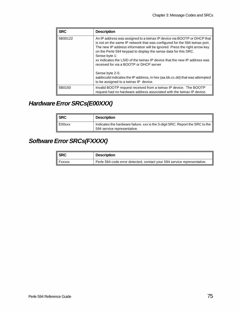
Chapter 3: Message Codes and SRCs
Hardware Error SRCs(E00XXX)
Software Error SRCs(FXXXX)
5B00122 An IP address was assigned to a twinax IP device via BOOTP or DHCP that is not on the same IP network that was configured for the 594 twinax port. The new IP address information will be ignored. Press the right arrow key on the Perle 594 keypad to display the sense data for this SRC.Sense byte 1:xx indicates the LSID of the twinax IP device that the new IP address was received for via a BOOTP or DHCP server
Sense byte 2-5:aabbccdd indicates the IP address, in hex (aa.bb.cc.dd) that was attempted to be assigned to a twinax IP device.
5B0150 Invalid BOOTP request received from a twinax IP device. The BOOTP request had no hardware address associated with the twinax IP device.
SRC Description
E00xxx Indicates the hardware failure. xxx is the 3-digit SRC. Report the SRC to the 594 service representative.
SRC Description
Fxxxxx Perle 594 code error detected, contact your 594 service representative.
SRC Description
Perle 594 Reference Guide 75

Chapter 3: Message Codes and SRCs
the 594
Utility Program Messages and SRCs This section describes message and System Reference Codes (SRCs) which are used byUtility Program.
594 Utility Program Installation Codes
The following SRC codes are displayed during the installation of the 594 Utility Program:
594 Utility Program Run Time Messages
The following messages are displayed when running the 594 Utility program:
SRC Description
0000 Installation complete
1010 Invalid destination drive. Restart the install program with a valid drive selection.
1020 Invalid mode parameter. Restart the install program with a valid selection (0,1,2, and blank).
1031 Invalid 5250 workstation address. Restart the install program with a valid drive selection (06).
1032 Invalid Token-Ring Address. Restart the install program with a valid Token-Ring Address.
1040 Invalid Token-Ring SAP. Restart the install program with a valid Token-Ring SAP.
1100 Invalid number of parameters. Restart the install program with valid parameters.
2000 Insufficient memory available to run the installation program. Free up at least 100 kb of memory and restart the installation program.
3000 Error reading the 594 Utility disk. Retry the 594 Utility installation, if the problem continues contact a service representative.
4000 Cannot create the destination directory. Restart the install program with a valid destination directory.
4001 Cannot write to destination drive. Verify drive and retry.
4002 Not enough disk space on destination drive. Restart the install program with a valid destination drive.
4005 Installation error. Retry the install program.
4007 Invalid run time parameters or options. Verify and restart the install program.
Message Description
594 Controller Software diskette build started... please wait
The controller is creating the 594 Base Controller Software diskette. This might take about 2 minutes.
594 Controller Software diskette file error
There is a problem with the 594 Base Controller Software diskette. Restart the 594 and use the backup diskette. If the problem persists, contact your service representative.
594 Controller Software diskette invalid
The diskette in the 594 diskette drive is not a valid 594 Base Controller Software diskette. Replace the diskette with the appropriate diskette and try again.
594 Controller Software diskette write protected
Remove the write protect and try again.
76 Perle 594 Reference Guide
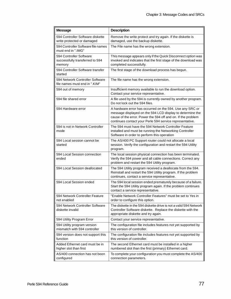
Chapter 3: Message Codes and SRCs
594 Controller Software diskette write protected or damaged
Remove the write protect and try again. If the diskette is damaged, use the backup diskette.
594 Controller Software file names must end in ".IMG"
The File name has the wrong extension.
594 Controller Software successfully transferred to 594 memory
This message appears only if the Quick Disconnect option was invoked and indicates that the first stage of the download was completed successfully.
594 Controller Software transfer started
The first stage of the download process has begun.
594 Network Controller Software file names must end in ".KIM"
The file name has the wrong extension.
594 out of memory Insufficient memory available to run the download option. Contact your service representative.
594 file shared error A file used by the 594 is currently owned by another program. Do not lock out the 594 files.
594 Hardware error A hardware error has occurred on the 594. Use any SRC or message displayed on the 594 LCD display to determine the cause of the error. Power the 594 off and on. If the problem continues contact your Perle 594 service representative.
594 is not in Network Controller mode
The 594 must have the 594 Network Controller Feature installed and must be running the Networking Controller Software in order to perform this operation
594 Local session cannot be started
The AS/400 PC Support router could not allocate a local session. Verify the configuration and restart the 594 Utility program.
594 Local Session connection ended
The local session physical connection has been terminated. Verify the 594 power and all cable connections. Correct any problem and restart the 594 Utility program.
594 Local Session deallocated The 594 Utility program received a deallocate from the 594. Reinstall and restart the 594 Utility program. If the problem continues, contact a service representative.
594 Local Session ended The 594 local session ended prematurely because of a failure. Start the 594 Utility program again. If the problem continues contact a service representative.
594 Network Controller Feature not enabled
"Enable Network Controller Features" must be set to Yes in order to configure this option.
594 Network Controller Software diskette invalid
The diskette in the 594 diskette drive is not a valid 594 Network Controller Software diskette. Replace the diskette with the appropriate diskette and try again.
594 Utility Program Error Contact your service representative.
594 Utility program version mismatch with 594 controller
The configuration file includes features not yet supported by this version of controller.
594 version does not support this function
The configuration file includes features not yet supported by this version of controller.
Added Ethernet card must be in higher slot than first
The second Ethernet card must be installed in a higher numbered slot than the first (primary) Ethernet card.
AS/400 connection has not been configured
To complete your configuration you must complete the AS/400 connection parameters.
Message Description
Perle 594 Reference Guide 77

Chapter 3: Message Codes and SRCs
AS/400 connection must be Frame Relay, Token Ring, or Ethernet
The AS/400 Connection must be configured for either Frame Relay, Token Ring or Ethernet before you can select Global Paramaters.
AS/400 Connection not Frame Relay
The AS/400 connection must be configured for frame relay before you can select Frame Relay Bridging.
ASCII interactive session with 594 not supported
PC Utility does not support interactive sessions through the ASCII feature card.
At least one DLCI must be configured
If LMI mode is set to No LMI and "Use Dynamically discovered DLCIs" is set to No then at least one DLCI must be configured
Bridge Filtering file exceeds 10000 bytes
The size of the FR-TR bridge filter file is greater than 10000 bytes in length.
Cannot disable Network Controller Features while configured
Remove all Network Controller feature configurations before attempting to disable the Network Controller Features.
Cannot find modem name for configured modem code
Select another modem code, or enter your own Initialization String.
Cannot select more than 1 controller for switched line
A switched AS/400 Attachment will only support one controller. Change the configuration to one controller only.
Card has not been defined for any slot
At least one Feature Card must be defined.
Communication Manager not started
The OS/2 communication manager has not been started for the 594 local session. Start the OS/2 communication manager for the 594 local session and retry.
Configuration contains features not supported
The configuration file has been created by a newer version of software. Upgrade to the newest version of the 594 Utility Program.
Configuration file is being saved Wait while the configuration file is being saved.
Controller IP address in same subnet as twinax IP address
An IP controller has been configured for a network that is a subnet of one of the twinax IP router ports
Controller IP Address is not in same network as IP Ports
All TCP/IP Controller IP addresses must be in one of the configured local IP networks.
Controller IP Address is same as Destination IP Address
All configured IP addresses must be unique.
Controller IP Address is same as Host IP Address
All configured IP addresses must be unique.
Controller IP Address same as IP Router Port IP Address
All configured IP addresses must be unique.
Controller IP Addresses are not in same network
All TCP/IP Controllers must be configured on the same IP network.
Controller is inactive The controller cannot be selected because it is inactive.
Controller Software not compatible with Utility
The software on the Controller Software Diskette does not support all features of the 594 Utility in use. Either use a Controller Software Diskette that supports the 594 Utility in use, or install the version of 594 Utility Program that is compatible with the Controller Software Diskette.
Controller wrong type The type of controller does not match the type of data requested.
Corresponding IP DLCI must be configured
A configured IP address in the IP DLCI table requires a DLCI number to be configured.
Message Description
78 Perle 594 Reference Guide

Chapter 3: Message Codes and SRCs
Could not reset LAN error counters
There is a communication problem between the controller and the PC Utility program.
Create software file operation was successful
The process of creating the 594 software file was completed successfully.
Data verified The data and selections on the current menu have been verified and are correct.
Date Time Synchronization already configured
The Synchronize Date and Time with Primary AS/400 System can only be configured on one emulated controller.
Default Gateway Address is not in same network as Controller
Default Gateway IP addresses must be in one of the configured local IP networks.
Default Gateway Address is not in same network as Ports
Default Gateway IP addresses must be in one of the configured local IP networks.
Default Gateway Address same as controller IP address
All configured IP addresses must be unique.
Default Gateway Address same as port IP address
All configured IP addresses must be unique.
Destination IP Address in same network as Controller
The Destination IP address in a IP Static Route Entry must not be in the same network of any of the configured local IP networks
Destination IP Address in same network as IP Router Ports
The Destination IP address in a IP Static Route Entry must not be in the same network of any of the configured local IP networks
DLCI IP Address must be configured
An IP address must be configured in the IP DLCI table.
Download was successful The complete process of transferring to the 594 controller and creating the 594 Software Diskette was completed successfully.
Duplicate controller addresses are configured
Two controllers have been configured with the same station address. Change the configuration so each controller has a unique address.
Duplicate controller TCP/IP addresses are configured
The same TCP/IP address has been configured for more than one controller in the 594.
Duplicate CP names are configured
All CP names configured for an AS/400 system must be unique. Change the configuration so that no CP name is duplicated on an AS/400 system.
Duplicate DLCI IP Addresses configured
All configured DLCI IP address must be unique
Duplicate DLCI Table Entries configured
All configured DLCI Table Entries must be unique
Duplicate Ethernet Gateway addresses configured
Two Ethernet cards have been configured with the same high order address.
Duplicate Logical Channels Configured
All logical channels configured for an AS/400 system must be unique. Change the configuration so that no logical channel is duplicated on an AS/400 system.
Duplicate LU names are configured
All LU names configured for an AS/400 system must be unique. Change the configuration so that no LU name is duplicated on an AS/400 system.
Duplicate Passwords configured All passwords configured for an AS/400 system must be unique. Change the configuration so that no password is duplicated on an AS/400 system.
Message Description
Perle 594 Reference Guide 79

Chapter 3: Message Codes and SRCs
Duplicate Router Port IP Addresses are configured
Two IP Router Ports have been configured with the same IP address
Duplicate Token-Ring Gateway addresses configured
Each Token-Ring Gateway requires a unique Token-Ring address.
Duplicated Destination exists A duplicate destination IP address exist in the Static IP Router Entries
Embedded Zeros found in IP Mask IP Mask is in an invalid format. Leading high bits of IP Mask must be consecutive ones followed by consecutive zeros. See PC Util help for detail
Error in creating Software File An error has occurred while trying to create a Software File for downloading to the 594
Error in downloading Software File An error occurred while downloading the software file to the 594, try the operation again
Error in getting concurrent diagnostic data
There is a communication problem between the controller and the PC Utility program.
Error with serial communication 594 Utility is having a communication problem with the serial connection to the 594. Verify correct COM port and cable conenction.
Ethernet card not defined for any slot
No Ethernet card has been installed. Therefore, Ethernet cannot be used for high order communication.
First Ethernet card must be in lowest available slot
The first (primary) Ethernet card must be installed in the lowest numbered available slot.
First Token-Ring card must be in slot 3
The 594 requires the first Token-Ring Feature card be installed in slot 3 of the 594. Verify and correct the configuration information before proceeding.
Frame Relay Bridging DLCI not unique
A FR-TR Bridge DLCI is the same as another FR-TR Bridge DLCI.
Frame Relay Bridging DLCIs must not match DLCIs for host(s)
A FR-TR Bridge DLCI is the same as a host DLCI.
Frame Relay Bridging not configured
"Frame Relay Bridging to Token-Ring" must set to Yes before you can select Frame Relay Bridging.
Frame Relay IP Routing not enabled
"Enable Network Controller Features" must be set to Yes in order to configure this option.
Frame Relay MAC Address same as Token Ring Gateway Address
The frame relay MAC address and the 594 token-ring LAN address are the same on a FR-TR bridge configuration.
Frame Relay Ring Number must be different from LAN Ring Number
The frame relay ring number and LAN ring number are the same on a FR-TR bridge configuration.
Function not available The function you have selected is not available because the menu choice is inappropriate or there is a mismatch with the current setup.
Group data does not match The emulated port parameters for all members of this group must be identical.
Hardware does not match User configuration
The 594 hardware configuration does not match the 594 user configuration data. Verify and correct the configuration information before proceeding.
Host Network names and LU names must be unique for all hosts
Two or more configured hosts were assigned the same name as the host network name and the LU name.
Message Description
80 Perle 594 Reference Guide
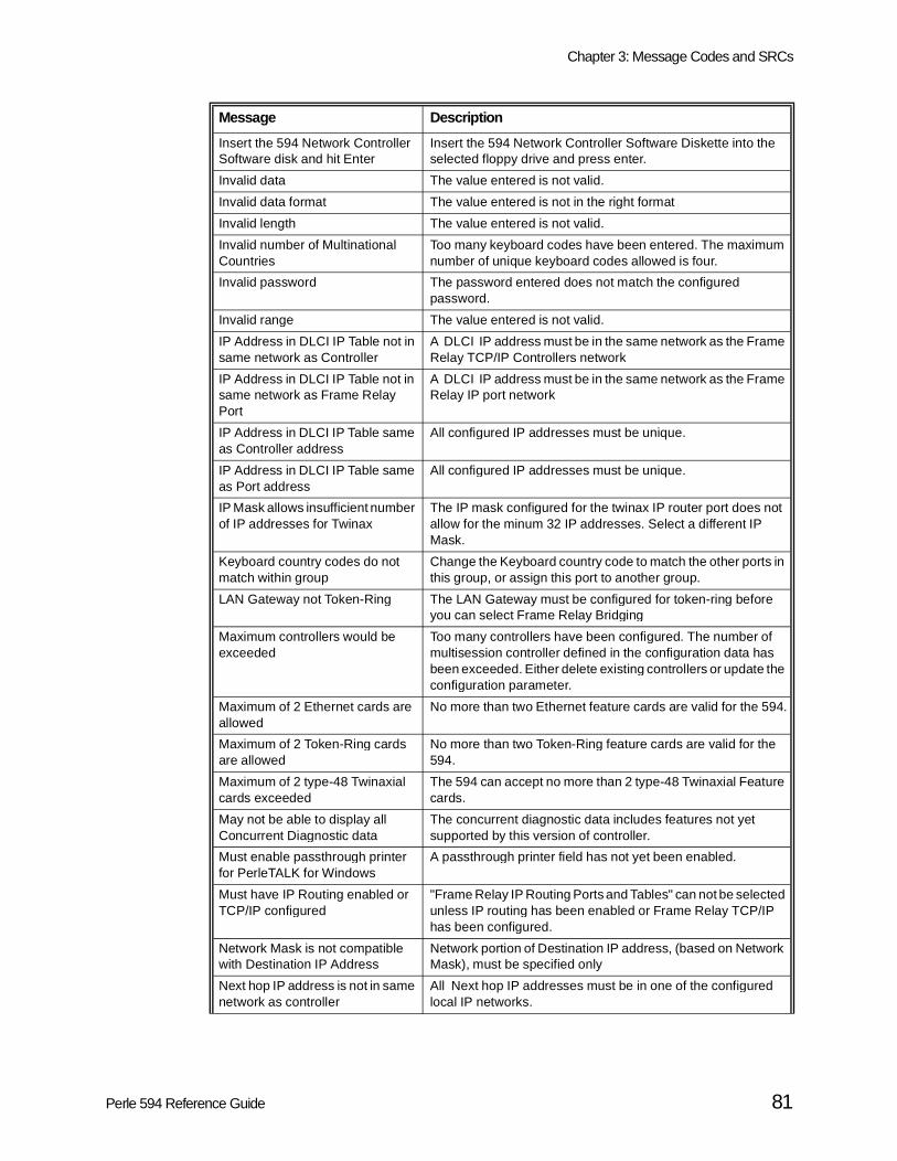
Chapter 3: Message Codes and SRCs
Insert the 594 Network Controller Software disk and hit Enter
Insert the 594 Network Controller Software Diskette into the selected floppy drive and press enter.
Invalid data The value entered is not valid.
Invalid data format The value entered is not in the right format
Invalid length The value entered is not valid.
Invalid number of Multinational Countries
Too many keyboard codes have been entered. The maximum number of unique keyboard codes allowed is four.
Invalid password The password entered does not match the configured password.
Invalid range The value entered is not valid.
IP Address in DLCI IP Table not in same network as Controller
A DLCI IP address must be in the same network as the Frame Relay TCP/IP Controllers network
IP Address in DLCI IP Table not in same network as Frame Relay Port
A DLCI IP address must be in the same network as the Frame Relay IP port network
IP Address in DLCI IP Table same as Controller address
All configured IP addresses must be unique.
IP Address in DLCI IP Table same as Port address
All configured IP addresses must be unique.
IP Mask allows insufficient number of IP addresses for Twinax
The IP mask configured for the twinax IP router port does not allow for the minum 32 IP addresses. Select a different IP Mask.
Keyboard country codes do not match within group
Change the Keyboard country code to match the other ports in this group, or assign this port to another group.
LAN Gateway not Token-Ring The LAN Gateway must be configured for token-ring before you can select Frame Relay Bridging
Maximum controllers would be exceeded
Too many controllers have been configured. The number of multisession controller defined in the configuration data has been exceeded. Either delete existing controllers or update the configuration parameter.
Maximum of 2 Ethernet cards are allowed
No more than two Ethernet feature cards are valid for the 594.
Maximum of 2 Token-Ring cards are allowed
No more than two Token-Ring feature cards are valid for the 594.
Maximum of 2 type-48 Twinaxial cards exceeded
The 594 can accept no more than 2 type-48 Twinaxial Feature cards.
May not be able to display all Concurrent Diagnostic data
The concurrent diagnostic data includes features not yet supported by this version of controller.
Must enable passthrough printer for PerleTALK for Windows
A passthrough printer field has not yet been enabled.
Must have IP Routing enabled or TCP/IP configured
"Frame Relay IP Routing Ports and Tables" can not be selected unless IP routing has been enabled or Frame Relay TCP/IP has been configured.
Network Mask is not compatible with Destination IP Address
Network portion of Destination IP address, (based on Network Mask), must be specified only
Next hop IP address is not in same network as controller
All Next hop IP addresses must be in one of the configured local IP networks.
Message Description
Perle 594 Reference Guide 81

Chapter 3: Message Codes and SRCs
Next hop IP Address is not in same network as IP Ports or IP Controllers
All Next hop IP addresses must be in one of the configured local IP networks.
Next hop IP address same as controller IP address
All configured IP addresses must be unique.
Next hop IP address same as port IP address
All configured IP addresses must be unique.
No .IMG files found Only files with an extension of ".IMG" can be selected for download.
No .KIM files found Only file with an extension of ".KIM" can be selected for Network Software download
No diskette or diskette is not a 594 Controller Software diskette
Either there is no diskette in the floppy drive or the diskette is not a 594 Controller Software diskette.
Not a 594 Controller Software diskette
The diskette currently in the floppy drive is not a 594 Controller Software diskette.
Not a 594 Network Controller Software diskette
The diskette currently in the floppy drive is not a 594 Network Controller Software diskette.
Not a physical NWS controller A physical NWS controller must be defined.
Not available: Ethernet AS/400 connection is configured
The Ethernet card cannot be used for LAN communication because it is already being used for host communication.
Not available: LAN Gateway is configured
The AS/400 connection cannot be Token-Ring or Ethernet if a LAN Gateway is configured. Verify and correct the configuration information before proceeding.
Not available: Token-Ring AS/400 connection is configured
A Token-Ring Gateway cannot be configured if the AS/400 connection is configured for Token-Ring. Verify and correct the configuration information before proceeding.
Operation complete The operation you selected has completed successfully.
Operation in progress The operation you selected is in progress.
Passthrough printer not valid for AS/400 PC Support
If you wish to use a Passthrough printer, select a different ASCII Display Type.
Physical NWS controller not configured
A Feature Card definition is required.
PWS disk error An error occurred writing to the 594 Controller Software Diskette. Replace or correct the disk and retry.
PWS disk is full There is not enough room on the PWS diskette to write the configuration file. Correct the diskette and retry.
PWS diskette is write protected Remove the write protect and retry.
PWS drive Not Ready The drive specified in the configuration file name is not ready. Insert the 594 diskette into the specified drive and retry.
PWS file access denied A file used by the 594 Utility program is access-protected. Assign the 594 Utility program access to this file.
PWS file error One of the text files in the "Menus" directory is invalid. Reinstall and then restart the 594 Utility program.
PWS file not found A file used by the 594 Utility program could not be found. Assign the 594 Utility program access to this file. Reinstall the 594 Utility program and retry.
PWS file open failure A file used by the 594 Utility program could not be opened. Assign the 594 Utility program access to this file. Reinstall the 594 Utility program and retry.
Message Description
82 Perle 594 Reference Guide

Chapter 3: Message Codes and SRCs
PWS file shared error A file used by the 594 Utility program is currently owned by another program. Do not lock out the 594 Utility program files. Reinstall the 594 Utility program and retry.
PWS incorrect diskette type or no diskette
Either there is no diskette in the PWS floppy drive or the diskette is not a 594 Controller Software diskette.
PWS invalid drive The drive specified in the configuration file name is not valid. Specify a valid drive.
PWS out of memory Insufficient memory available to run the program. Refer to Chapter 7 for system requirements.
PWS path not found A path used by the 594 Utility program could not be found. Assign the 594 Utility program access to this file. Reinstall the 594 Utility program and retry.
PWS router is not installed The AS/400 PC Support router has not been installed and is required by the 594 Utility program. Install the AS/400 PC Support program and then reinstall the 594 Utility program and retry.
PWS too many open files The operating system has too many files open. Verify that other programs are not accessing the 594 Utility program files. Reinstall the 594 Utility program and retry.
Rebooting 594. Wait 5 min. before restarting Utility
The 594 is being rebooted. This takes about 5 minutes.
Required field A value must be entered in the current field.
Required field - AS/400 TCP/IP Address
A host TCP/IP address has not yet been defined.
Required field - Controller TCP/IP Address
A controller TCP/IP address has not yet been defined.
Required field - Frame Relay Bridging
Frame Relay Bridging information must be configured if "Frame Relay Bridging to Token-Ring" has been set to Yes.
Required field - Frame Relay IP Routing
Frame Relay IP Routing information must be configured if "Enable Frame Relay IP routing" has been set to Yes.
Required field - Logical Channel An logical channel number has not been entered for a configured AS/400 system.
Required Field - Network Information
The Network Information has not been completed for all controllers selected.
Required field - Station Address A station address has not been entered for all the controllers selected.
Router port IP address in same subnet as twinax IP address
An IP router port has been configured with a network that is a subnet of one of the twinax IP router ports
Router Port IP Address is same as Host IP Address
All configured IP addresses must be unique.
Save completed The configuration data has been saved.
Selected file is not a 594 Controller Software file
Be sure you select a 594 Controller Software file.
The configuration file is not for a 594M controller.
The configuration file that was the Utility tried to open was not configured for a 594M controller.
This entry is incomplete All the required field in a table entry have not been configured
To use dynamically discovered DLCIs, LMI must not be set to NO
Either set LMI mode to ANSI Annex D or CCITT or set "Use dynamically discovered DLCIs" to No
Message Description
Perle 594 Reference Guide 83

Chapter 3: Message Codes and SRCs
Token-Ring card not defined for slot 3
To configure the AS/400 connection as Token-Ring, a Token-Ring card must be installed in slot 3 of the 594.
Version mismatch between Network and Base diskettes
The software version of the Base and Network Controller Software diskettes must be the same
Message Description
84 Perle 594 Reference Guide

ddress
t only.
k, or
ontrolcular,
hen
efault
g the or
Chapter 4: Specifying Ethernet Address Formats
When configuring an Ethernet host or gateway attachment you need to specify the Ethernet Aoption in one of two formats:
• Ethernet address format
• Token-Ring address format.
Using Ethernet address format Use Ethernet address format if the LAN connection between your controller and host is Etherne
Using Token-Ring address format Use Token-Ring address format when:
• your controller is attached to Ethernet and there are Token-Ring segments in your networ
• your network is designed to use the Token-Ring address format.
Every LAN device on the network has a unique physical address, known as the Media Access C(MAC) address. The format for this address is different for Token-Ring and Ethernet. In partithe bit order with each byte of the address is reversed.
Refer to the procedure on the following page when using Token-Ring address format.
Converting Token-Ring address formats
Use the following procedure to convert the LAN address before entry into configuration wspecifying Token-Ring address format:
1. Write out the 12-digit Perle 594 LAN address separating it into 6 pairs. For example, the d594 LAN address is written as:
2. Use the Pair Conversion Table on the following page to locate the conversion pair by usinfirst digit of each pair as a row coordinate and the second digit as a column coordinate. Fexample:
400059400003
⇓ ⇓ ⇓ ⇓ ⇓ ⇓40 00 59 40 00 03
40 00 59 40 00 03
4 0 0 0 5 9 4 0 0 0 0 3
⇓ ⇓ ⇓ ⇓ ⇓ ⇓ ⇓ ⇓ ⇓ ⇓ ⇓ ⇓Pair Conversion Table
⇓ ⇓ ⇓ ⇓ ⇓ ⇓02 00 9A 70 00 C0
Perle 594 Reference Guide 85

Chapter 4: Specifying Ethernet Address Formats
3. Combine the 6 converted pairs into a 12-digit LAN address. For example:
Pair Conversion Table
Enter the converted address into the related field in configuration data.
02 00 9A 70 00 C0
⇓ ⇓ ⇓ ⇓ ⇓ ⇓02009A7000C0
2nd Char →(Column)1st Char ↓ (Row) 0 1 2 3 4 5 6 7 8 9 A B C D E F
0 00 80 40 C0 20 A0 60 E0 10 90 50 D0 30 B0 70 F0
1 08 88 48 C8 28 A8 68 E8 18 98 58 D8 38 B8 78 F8
2 04 84 44 C4 24 A4 64 E4 14 94 54 D4 34 B4 74 F4
3 0C 8C 4C CC 2C AC 6C EC 1C 9C 5C DC 3C BC 7C FC
4 02 82 42 C2 22 A2 62 E2 12 92 52 D2 32 B2 72 F2
5 0A 8A 4A CA 2A AA 6A EA 1A 9A 5A DA 3A BA 7A FA
6 06 86 46 C6 26 A6 66 E6 16 96 56 D6 36 B6 76 F6
7 0E 8E 4E CE 2E AE 6E EE 1E 9E 5E DE 3E BE 7E FE
8 01 81 41 C1 21 A1 61 E1 11 91 51 D1 31 B1 71 F1
9 09 89 49 C9 29 A9 69 E9 19 99 59 D9 39 B9 79 F9
A 05 85 45 C5 25 A5 65 E5 15 95 55 D5 35 B5 75 F5
B 0D 8D 4D CD 2D AD 6D ED 1D 9D 5D DD 3D BD 7D FD
C 03 83 43 C3 23 A3 63 E3 13 93 53 D3 33 B3 73 F3
D 0B 8B 4B CB 2B AB 6B EB 1B 9B 5B DB 3B BB 7B FB
E 07 87 47 C7 27 A7 67 E7 17 97 57 D7 37 B7 77 F7
F 0F 8F 4F CF 2F AF 6F EF 1F 9F 5F DF 3F BF 7F FF
86 Perle 594 Reference Guide

Chapter 5: TCP/IP White Paper
This appendix contains a copy of the Perle White Paper 594 and AS/400 TCP/IP Configuration
Perle 594 Reference Guide 87

Chapter 5: TCP/IP White Paper
88 Perle 594 Reference Guide

P E R L E W H I T E P A P E R
594 and AS/400 TCP/IP Configuration
95-2435-02
Perle 594 Reference Guide 89

P E R L E W H I T E P A P E R
ns and native/IP forctureith the
e in theP/IP).
tallationstablish on the
st load these at the
OverviewUsing the Perle’s enhanced 5494 compatible controller, it is now possible to support native SNA applicatiodevices over your TCP/IP network. The Perle 594 looks like a 5494 compatible workstation controller to5250 devices and LAN attached workstations but is able to take the SNA traffic and convert it into TCPdelivery over the network. The 594 accomplishes this by integrating IBM’s implementation of MPTN architeinto the 594 controller. This means that the 594 provides 5250 devices and LAN attached workstations wequivalent of the AnyNet router that runs inside client applications on intelligent workstations.
The information in this white paper is intended for customers and Perle technical professionals who arprocess of, or planning to connect Perle 594 TCP/IP controllers to their AS/400 via Anynet (APPC over TCThis white paper will discuss the following major topics:
• AS/400 System Requirements
• AS/400 and AnyNet (APPC over TCP/IP) Configuration
• 594 Configuration
• Verification of the APPC over TCP/IP Configuration
• Performance and Operation Considerations
AS/400 System Requirements:The AnyNet/400 APPC over TCP/IP code is part of the base OS/400 V3R1 code. There are no special insrequirements. You must be running AS/400 with V3R1 or a later OS/400 version in order to configure and ecommunication with the 594 TCP/IP controller. IBM has made several fixes to the TCP/IP and AnyNet codeAS/400, so it is strongly recommended that your AS/400 be at the latest PTF level.
If you do not wish to load the latest AS/400 Cumulative PTF package in it’s entirety then you should at leaany PTF’s related to TCP/IP, AnyNet and APPN/APPC. To find out more information on what is contained inPTF packages you can look at the IBM AS/400’s Preventive Service Planning (PSP) Information web sitefollowing URL:
http:/www.as400service.ibm.com/as4sde/sline003.nsf/sline003home
90 Perle 594 Reference Guide

P E R L E W H I T E P A P E R
accessllowing
tem in
ation. refer
wouldrts only
AS/400 and AnyNet (APPC over TCP/IP) ConfigurationThe following OS/400 configuration steps are required to successfully bring up a 594 TCP/IP controller:
1. Establish a TCP/IP Configuration between the AS/400 System and the 594
2. Change the Network Attribute ALWANYNET to *YES
3. Create APPC Controller with LINKTYPE (*ANYNW)
4. Create RWS Controller and NWS Devices Descriptions
5. Add Entries to the APPN Remote Location List
6. Map 594 LU name to an Internet Address
7. Start TCP/IP
The user ID under which the APPC over TCP/IP configurations are created, must have sufficient authority tothe relevant commands. Some of the commands require the user ID to have the IOSYSCFG authority. The foexamples shown here were created using a profile with QSECOFR authority.
In the following sections we will create the necessary OS/400 configurations for the “PERLE” AS/400 sysFigure 1. They will illustrate the configuration steps required for this 594 TCP/IP configuration example.
Figure 1. 594 Configured for Two Controllers Connected via APPC over TCP/IP
Note : In this White Paper we use a 594 TCP/IP over Token-Ring configuration for our sample configurIf you wish to view other sample 594 configurations using TCP/IP over Ethernet or Frame Relayto “AS/400 Configuration Examples” section in the Perle User and Reference Guide.
In our example configuration we used a Perle 594e controller. The configuration for a Perle 594T controllerbe the same except for the limitations in the number of controllers that can be configured. The 594M suppoone controller.
101.102.200.56
101.102.200.1 101.102.100.1
101.102.100.30CE594e01
101.102.100.31C594e02
AS/400PERLE 594e TCP/IP
Controller
NWSDisplay
NWSDisplay
Local IPRouter
7ESC PF1 PF2
D
A
E
B
F
C
Req
Slot Clear
Ctrl Enter
PF3
Alt
0
8 9
4 5 6
1 2 3
Ready
Call 494E Service
See PD Guide
Test Mode
Perle 494001-014 9 4
7ESC PF1 PF2
D
A
E
B
F
C
Req
Slot Clear
Ctrl Enter
PF3
Alt
0
8 9
4 5 6
1 2 3
Ready
Call 494E Service
See PD Guide
Test Mode
Perle 494001-014 9 4
Local TCP/IPNetwork
Remote TCP/IPNetwork
Remote IPRouter
Perle 594 Reference Guide 91

P E R L E W H I T E P A P E R
remoterk with
ceed to remote
n does
1. Establish a TCP/IP configuration between the AS/400 system and the 594In this section we show the basic steps to establish a TCP/IP configuration between your AS/400 and thenetwork where your 594 is situated. If your system already has a TCP/IP configuration to the remote netwowhich you want to communicate with your 594 via APPC over TCP/IP, then you can skip this step and prostep 2 in this section. The basic steps to establish a TCP/IP configuration between your AS/400 and thenetwork are:
• Create an AS/400 Line Description.
• Add a TCP/IP Interface
• Add a TCP/IP Route
Create an AS/400 Line Description
The AS/400 line description defines the physical interface to the network. If an appropriate line descriptionot already exist (they can be shared), you will need to create one. Here we use the CRTLINTRN command tocreate a token-ring line description.
Figure 2. Creating a Token-Ring Line Description
Create Line Desc (Token-Ring) (CRTLINTRN)
Type choices, press Enter. Line description . . . . . . . .> TCPTKRN Name Resource name . . . . . . . . .> LIN061 Name, *NWID, *NWSD Online at IPL . . . . . . . . . *YES *YES, *NO Vary on wait . . . . . . . . . *NOWAIT *NOWAIT, 15-180 (1 second) Maximum controllers . . . . . . 40 1-256 Line speed . . . . . . . . . . .> 16M 4M, 16M, *NWI Maximum frame size . . . . . . . 1994 265-16393, 265, 521, 1033... Local adapter address . . . . . *ADPT 400000000000-7FFFFFFFFFFF... Exchange identifier . . . . . . *SYSGEN 05600000-056FFFFF, *SYSGEN SSAP list: Source service access point . *SYSGEN 02-FE, *SYSGEN SSAP maximum frame . . . . . . *MAXFRAME, 265-16393 SSAP type . . . . . . . . . . *CALC, *NONSNA, *SNA, *HPR + for more values Text 'description' . . . . . . . *BLANK Bottom F3=Exit F4=Prompt F5=Refresh F10=Additional parameters F12=Cancel F13=How to use this display F24=More keys
92 Perle 594 Reference Guide

P E R L E W H I T E P A P E R
of an IP
s. Eaching to each, you
rfaces.
and end
tem andld.
he Opt
Add a TCP/IP Interface
The TCP/IP interface defines the AS/400 on the TCP/IP network. The interface defines the association address with a line description on your AS/400.
Each line description that is associated with a physical communications line can have several interfaceinterface must have a unique IP address. These IP addresses are the IP addresses that you are assigninterface on this AS/400. They are not the IP addresses for any other systems in the network. In most casesonly need one IP interface address on your AS/400
Enter CFGTCP command to access the Configure TCP/IP panel, and select option 1 to work with TCP/IP inte
Figure 3. Work with TCP/IP Interfaces display
Besides allowing you to add, change and remove TCP/IP interfaces, this screen also allows you to startthese interfaces
If a TCP/IP interface does not already exist, add an entry using the internet address allocated to your systhe mask of the subnet in which your communication line is connected to, by entering a 1 under the Opt fie
Figure 4. Add TCP/IP Interface display
If TCP/IP is already started on your AS/400 system then you will need to start the interface by typing 9 in tfield beside the TCP/IP interface you have just added.
Work with TCP/IP Interfaces System: PERLE Type options, press Enter. 1=Add 2=Change 4=Remove 5=Display 9=Start 10=End
Internet Subnet Line Line Opt Address Mask Description Type 1 _______________ __ 127.0.0.1 255.0.0.0 *LOOPBACK *NONE
Bottom F3=Exit F5=Refresh F6=Print list F11=Display interface status F12=Cancel F17=Top F18=Bottom
Add TCP/IP Interface (ADDTCPIFC) Type choices, press Enter.
Internet address . . . . . . . . > '101.102.200.56' Line description . . . . . . . . TCPTKRN Name, *LOOPBACK Subnet mask . . . . . . . . . . 255.255.255.0 Type of service . . . . . . . . *NORMAL *MINDELAY, *MAXTHRPUT... Maximum transmission unit . . . *LIND 576-16388, *LIND Autostart . . . . . . . . . . . *YES *YES, *NO PVC logical channel identifier 001-FFF + for more values X.25 idle circuit timeout . . . 60 1-600 X.25 maximum virtual circuits . 64 0-64 X.25 DDN interface . . . . . . . *NO *YES, *NO TRLAN bit sequencing . . . . . . MSB *MSB, *LSB
Bottom F3=Exit F4=Prompt F5=Refresh F12=Cancel F13=How to use this display F24=More keys
Perle 594 Reference Guide 93

P E R L E W H I T E P A P E R
residesst one
definedrfaces,des on.
ork to to the
icit route
tes. If
xample
Add a TCP/IP Route
A route entry provides the connection between your AS/400 system and an external network. If your 594in a different network or subnetwork to your AS/400 via an IP router, it will be necessary to configure at learoute entry. This route entry can be a default route or an explicit route entry. If just one TCP/IP interface is on your AS/400 system then a default route entry will do. If, however, you have defined multiple TCP/IP inteit is recommended that you to add an explicit route entry for every subnetwork that your 594 controller resiIt is possible to have multiple default routes, but it is not recommended.
The default route tells the AS/400 system to route any traffic for locations that are not on the local subnetwthe IP router. An explicit route entry prompts the AS/400 to route frames destined for a specific subnetworkIP router. The router handles delivering the packets to their destination IP address whether a default or explentry is used.
To define a default route, return to the Configure TCP/IP menu and select Option 2, Work with TCP/IP rouan appropriate route entry does not already exist, add a route entry by entering a 1 under the Opt field. Figure 5 andFigure 6 below show the required parameters for a default route entry and an explicit route entry for the econfiguration in Figure 1.
Figure 5. Work with TCP/IP Routes display - Default Route Entry
Figure 6. Work with TCP/IP Routes display - Explicit Route Entry
Work with TCP/IP Routes System: PERLE Type options, press Enter. 1=Add 2=Change 4=Remove 5=Display Type Route Subnet of Next Opt Destination Mask Service Hop __ _______________ _______________ __________ _______________ __ *DFTROUTE *NONE *NORMAL 101.102.200.1
Bottom F3=Exit F5=Refresh F6=Print list F12=Cancel F17=Top F18=Bottom
Work with TCP/IP Routes System: PERLE Type options, press Enter. 1=Add 2=Change 4=Remove 5=Display
Type Route Subnet of Next Opt Destination Mask Service Hop __ _______________ _______________ __________ _______________ __ 101.102.100.0 255.255.255.0 *NORMAL 101.102.200.1
Bottom F3=Exit F5=Refresh F6=Print list F12=Cancel F17=Top F18=Bottom
94 Perle 594 Reference Guide

P E R L E W H I T E P A P E R
nstead
TCP),esidual
at thed “
lay the
TCP/s being connectt active andtrollers
nds that
P/re will paths will these
P/IPe the
stand
et.
me-Ss.
PC
It is recommended that the *IFC option be selected for the Maximum Transmission Unit (MTU) parameter iof the default value of 576 (refer to “Performance and Operation Considerations” later in this document).
Note : If you are removing any TCP/IP Interfaces it is strongly recommended that you stop TCP/IP (ENDand start TCP/IP (STRTCP) again in order to make sure the AS/400 has properly removed rinformation about that TCP/IP interface’s IP address.
2. Change the Network Attribute ALWANYNET to *YESChanging this network attribute will allow APPC over TCP/IP to run on your system. If you are not sure whparameter is set to, enter DSPNETA at the AS/400 command prompt. Page down to the last page and finAllowAnyNet Support”.
If the value is *NO, then enter the following command:
CHGNETA ALWANYNET (*YES)
After changing this attribute, you can verify the change by entering the DSPNETA command again to dispparameter.
3. Create APPC controller with LINKTYPE (*ANYNW)A new LINKTYPE has been added to the APPC controller description for APPC over TCP. With APPC overIP, the APPC controller is no longer directly attached to a line description but rather can be thought of adefined as an AS/400 AnyNet class of service. Because of this fact, when a PWS or a 594 controller tries toto the AS/400 via APPC over TCP/IP, the AS/400 seems to couple that APPC over TCP device with the firsAPPC controller defined as *ANYNW. As a result, if you have multiple AnyNet APPC controllers definedactive on your AS/400, the same 594 or PWS will randomly come up under any of these defined APPC conevery time they connect via APPC over TCP/IP. Because of this behavior on the AS/400, Perle recommeyou use one of the following two methods for configuring your AnyNet APPC controllers on your AS/400.
Method 1: Define an AnyNet APPC Controller for Each 594 TCP/IP Controller
Using this method an APPC controller with LINKTYPE (*ANYNW) is defined for each 594 TCIP controller. Note that no other AnyNet APPC controllers should be defined on the AS/400. If otheAnyNet APPC controller are created then you run the risk that your 594 controller APPC devicautocreate under the additional APPC controllers and will NOT allow NWS devices to find aback to the controller. These AnyNet APPC controllers you define for the 594 TCP/IP controllerbe used by any PWSs connected via APPC over TCP/IP. The RMTCPNAME for each ofAnyNet APPC controllers should match your CP and LU names configured for each 594 TCcontroller. Use the CRTCTLAPPC (create APPC Controller Description) command to creatAnyNet APPC for each controller. For our example configuration in Figure 1. you would enter thefollowing two commands on the AS/400 command prompt:
CRTCTLAPPC CTLD(c594e01) LINKTYPE(*ANYNW) RMTCPNAME(c594E01) RMTNETID(*NETATR)
CRTCTLAPPC CTLD(c594E02) LINKTYPE(*ANYNW) RMTCPNAME(c594e02) RMTNETID(*NETATR)
Benefits:
• More traditional way of configuring 5494 type controllers and easier conceptually to under
• Each AnyNet controller allows a combination of 254 594s and PWSs connected via AnyN
Disadvantages:
• AnyNet PWSs will randomly come up under the different 594 APPC controllers. This is sotimes confusing and makes it hard to find the APPC device descriptions for individual PW
• 594 controller APPC device descriptions may randomly come under different AnyNet APcontrollers, which can be confusing but does NOT affect operation.
Perle 594 Reference Guide 95

P E R L E W H I T E P A P E R
illyNetP/IP
e this
just
ach ted
or laterpport bycreate
e device
or eachcation remote
o create
Method 2: Define a Single AnyNet APPC Controller
Using this method, only one AnyNet APPC controller is defined on your AS/400 system and it wbe used for all PWSs and 594s connected via APPC over TCP/IP. The RMTCPNAME for this AnAPPC controller should not match the CP and LU names configured on any of your 594 TCcontrollers. Use the CRTCTLAPPC (create APPC Controller Description) command to creatAnyNet APPC controller. For our example configuration in Figure 1. you would enter the followingcommand on the AS/400 command prompt:
CRTCTLAPPC CTLD(anynetappc) LINKTYPE(*ANYNW)RMTCPNAME(anyntctl)RMTNETID(*NETATR)
Benefits:
• Easy to locate all AnyNet APPC devices
• No need to configure APPC AnyNet controllers for each 594 TCP/IP controller added, youneed to add a remote location list entry
Disadvantages
• Limited to no more than a combination of 254 PWSs and 594s connected via AnyNet. AnAnyNet APPC controller can only have up to 254 APPC devices associated with it and ePWS and 594 connected via AnyNet requires an APPC device to be auto/manually creaunder the AnyNet APPC controller.
4. Create RWS Controller and NWS Devices Descriptions
For every 594 TCP/IP controller a remote workstation controller needs to be created. With OS/400 V3R1 the RWS controller device description can be automatically created by the AS/400 system. Enable this susetting the system value autoconfigure remote controller (QAUTORMT) to ON (1). If you wish to manually the RWS controller, then for the configuration example shown in Figure 1. you would enter the followingcommands on the AS/400 command prompt:
CRTCTLRWS CTLD(c594e01r) TYPE(5494) MODEL(2) LINKTYPE (*NONE) RMTLOCNAME(c594e01) AUTOCRTDEV (*ALL)CRTCTLRWS CTLD(c594e02r) TYPE(5494) MODEL(2) LINKTYPE (*NONE) RMTLOCNAME(c594e02) AUTOCRTDEV (*ALL)
The 594 attached NWS device descriptions are automatically created by the host by setting autocreat(AUTOCRTDEV) to *ALL in the RWS controller description as shown above.
5. Add Entries to the APPN Remote Location List.To Communicate using APPC over TCP/IP support, the AS/400 system requires a configuration list entry f594 TCP/IP controller. The APPC over TCP/IP communications uses the information in the APPN remote lolist to determine which controller description to use when it activates an NWS session. To update the APPNconfiguration list, use the following command:
CHGCFGL *APPNRMT
The following two figures show what entries you would add depending on the method you used in step 3 tyour AnyNet APPC controller(s).
96 Perle 594 Reference Guide

P E R L E W H I T E P A P E R
ile ther(s).
Figure 7. AS/400 APPN Remote Location List Panel (Method 1)
Figure 8. AS/400 APPN Remote Location List Panel (Method 2)
The remote location names must match the RMTLOCNAME names entered in the RWS controllers whremote control point name must match the RMTCPNAME name(s) entered in the AnyNet APPC controlle
Change Configuration List PERLE 07/21/97 18:21:03 Configuration list . . : QAPPNRMT Configuration list type : *APPNRMT Text . . . . . . . . . :
Type changes, press Enter.
----------------------------APPN Remote Locations------------------------------ Remote Remote Control Remote Network Local Control Point Location Secure Location ID Location Point Net ID Password Loc C594E01 *NETATR *NETATR C594E01 *NETATR ________________ *NO C594E02 *NETATR *NETATR C594E02 *NETATR ________________ *NO ________ *NETATR *NETATR ________ *NETATR ________________ *NO ________ *NETATR *NETATR ________ *NETATR ________________ *NO ________ *NETATR *NETATR ________ *NETATR ________________ *NO ________ *NETATR *NETATR ________ *NETATR ________________ *NO ________ *NETATR *NETATR ________ *NETATR ________________ *NO ________ *NETATR *NETATR ________ *NETATR ________________ *NO
More... F3=Exit F11=Display session information F12=Cancel F17=Top F18=Bottom
Change Configuration List PERLE 07/21/97 18:35:03 Configuration list . . : QAPPNRMT Configuration list type : *APPNRMT Text . . . . . . . . . :
Type changes, press Enter. ----------------------------APPN Remote Locations----------------------------- Remote Remote Control Remote Network Local Control Point Location Secure Location ID Location Point Net ID Password Loc C594E01 *NETATR *NETATR ANYNTCTL *NETATR ________________ *NO C594E02 *NETATR *NETATR ANYNTCTL *NETATR ________________ *NO ________ *NETATR *NETATR ________ *NETATR ________________ *NO ________ *NETATR *NETATR ________ *NETATR ________________ *NO ________ *NETATR *NETATR ________ *NETATR ________________ *NO ________ *NETATR *NETATR ________ *NETATR ________________ *NO ________ *NETATR *NETATR ________ *NETATR ________________ *NO ________ *NETATR *NETATR ________ *NETATR ________________ *NO
More... F3=Exit F11=Display session information F12=Cancel F17=Top F18=Bottom
Perle 594 Reference Guide 97

P E R L E W H I T E P A P E R
work IDonfigure
e entered
Theary.
rs, select TCP/ started
RKr FTP,ssage
e TCP/
6. Map 594 LU names to an Internet addressThe AS/400 TCP/IP host table provides the mapping between the SNA remote location name/remote netof the 594 TCP/IP controller and a remote internet address. Enter the CFGTCP command to access the CTCP/IP panel, and select option 10 to work with the TCP/IP host table.
Figure 9. AS/400 TCP/IP Host Table Entries
The IP address entered must match the remote IP address of your 594 TCP/IP controller. The host nammust be in the form rmtlocname.appn.sna.ibm.com, where
The SNA domain suffix is needed for AnyNet (APPC over TCP/IP) communications in SNA networks. AnyNet standard for SNA domain suffix is sna.ibm.com and you should not change it unless absolutely necess
7. Start TCP/IPBefore any TCP/IP services are available, the TCP/IP servers must be started. To start all TCP/IP serveoption 3 from the TCP/IP Administration menu (GO TCPADM). Option 3 starts TCP/IP processing, starts theIP interfaces, and starts the TCP/IP server jobs. Note that the APPC over TCP/IP servers cannot beindividually.
Allow a few moments for TCP/IP to start, then select Option 20, Work with TCP/IP jobs in the QSYSWsubsystem from the TCP/IP Administration menu. The job QTCPIP should be in the list (along with jobs foPOP, TELNET, LPD and SMTP). To check for the successful start of TCP/IP, enter the following Display Mecommand at the AS/400 prompt:
DSPMSG QTCP
Note : You must start TCP/IP whenever all subsystems are ended or you IPL the AS/400 system. To havIP start automatically after an IPL, you need to change the IPL start-up program.
rmtlocname is the RMTLOCNAME entered in the RWS controller
appn is the remote network ID of the 594 TCP/IP controller
sna.ibm.com is the SNA domain suffix
Work with TCP/IP Host Table Entries
System: PERLE Type options, press Enter. 1=Add 2=Change 4=Remove 5=Display 7=Rename
Internet Host Opt Address Name __ _______________ __ 101.102.100.30 C594E01.PLSNET.SNA.IBM.COM __ 101.102.100.31 C594E02.PLSNET.SNA.IBM.COM __ 127.0.0.1 LOOPBACK
Bottom F3=Exit F5=Refresh F6=Print list F12=Cancel F17=Position to
98 Perle 594 Reference Guide

P E R L E W H I T E P A P E R
. Referty
the 594).
t KeepAS/400n the 594Alivea usefuln time.
u00o come
594 ConfigurationIn order to create a 594 TCP/IP configuration you must use Perle’s 594 Utility Program in enhanced modeto Perle’s 594 User and Reference Guide for details on installing and navigating through the 594 Utiliconfiguration screens.
From the 594 - Configuration screen of every controller card you are configuring for TCP/IP, select the AS/400Connection menu, TCP/IP and then Token-Ring, Ethernet or Frame Relay. For our example configuration in Figure1. you would select Token-Ring.
Figure 10. 594 Utility: AS/400 Connection - TCP/IP Token-Ring Panel
Note that the Default Gateway IP Address entered should be the IP address of the remote router, (local to
The AnyNet Keep Alive Duration field is used to set the duration in minutes that the 594 will send out AnyNeAlive messages, at 30 second intervals for each configured controller, to verify that the connection to the is still established. If the 594 gets no responses to the Keep Alive messages for the duration specified, thewill bring down all TCP/IP connection for that controller. If this value is set to zero then the AnyNet Keep timer is turned off and the 594 also informs the AS/400 not to send AnyNet Keep Alive messages. This is setting if you are communicating over a network, (like ISDN), where you are charged for network connectio
Then select the Network Information menu from the 594 - configuration screen. It is recommended that yoconfigure the Continuous Retry field to YES so that the 594 will continuously try to reconnect with your AS/4if you loose communication. This is useful in the case were your AS/400 is IPLed and you want your 594s tback up without any user intervention.
Perle 594 Reference Guide 99
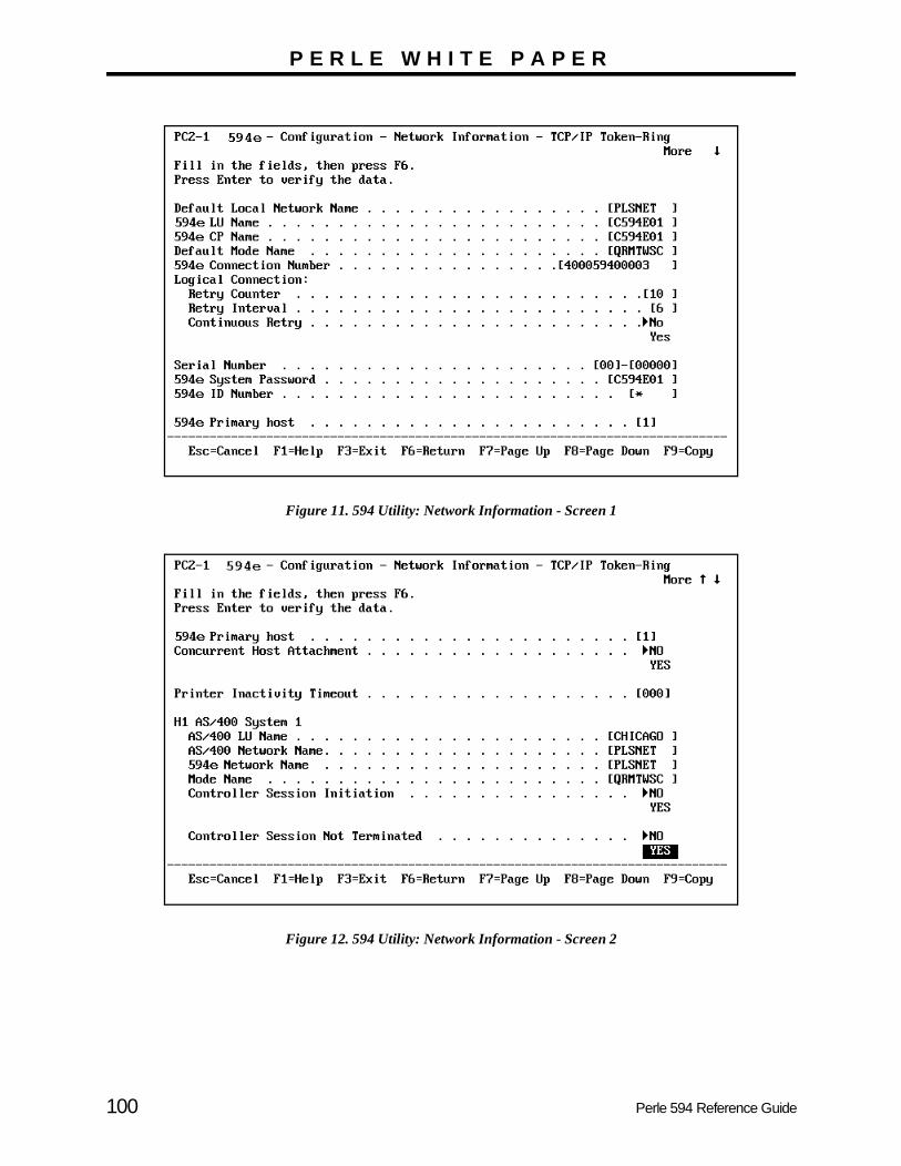
P E R L E W H I T E P A P E R
Figure 11. 594 Utility: Network Information - Screen 1
Figure 12. 594 Utility: Network Information - Screen 2
100 Perle 594 Reference Guide

P E R L E W H I T E P A P E R
. Thisxample400
ollowingdetailed
TCP/IP
Verification of the APPC over TCP/IP ConfigurationThe verification of the APPC over TCP/IP should be carried out in the following stages:
• Verify the TCP/IP Configuration Between the AS/400 and the 594
• Verify the APPC over TCP/IP Configuration Between the AS/400 and the 594
Verify the TCP/IP Configuration Between the AS/400 and the 594
Before you verify the APPC over TCP/IP configuration, you should verify the native TCP/IP configurationcan be done in such a way that it also verifies part of the APPC over TCP/IP configuration. From our econfiguration in Figure 1, entering the following command will verify the TCP/IP connection between the AS/(PERLE) and the 594 via the APPC over TCP/IP host table entry:
ping c594e01.plsnet.sna.ibm.com
If the PING operation is successful, the job log should contain messages that are similar to the ones in the ffigure. To view the messages, use the Display Job Log (DSPJOBLOG) command, press F10 to display message and then Page Up.
Figure 13. AS/400 PING Command Job Log information
Repeat this ping command for every 594 controller you have configured. Once you are satisfied that the configuration is working correctly then you can move on to verify the APPC over TCP/IP configuration.
ping c594e01.plsnet.sna.ibm.com Verifying connection to host system C594E01.PLSNET.SNA.IBM.C at address 101.102.100.31. Connection verification 1 took .033 seconds. 1 successful connection verifications. Connection verification 2 took .014 seconds. 2 successful connection verifications. Connection verification 3 took .017 seconds. 3 successful connection verifications. Connection verification 4 took .015 seconds. 4 successful connection verifications. Connection verification 5 took .036 seconds. 5 successful connection verifications. Round-trip (in milliseconds) min/avg/max = 14/23/36
Perle 594 Reference Guide 101

P E R L E W H I T E P A P E R
WRK) active
portry to
eated
Verify the APPC over TCP/IP Configuration Between the AS/400 and the 594
First you should check that the APPC over TCP/IP job is running. The command WRKACTJOB SBS(QSYSwill display the active jobs in the QSYSWRK subsystem. The APPC over TCP/IP job QAPPCTCP should beas shown in the following figure.
Figure 14. Work with Active Jobs Panel
If you look at the job log associated with QAPPCTCP, you should see the following:
Figure 15. Display Job Log (QAPPCTCP) Panel
Note : The APPC over TCP/IP job (QAPPCTCP) is initially started when the Allow AnyNet sup(ALWANYNET) network attribute is changed to *YES. If the job fails for any reason, it is necessastop TCP/IP (ENDTCP), and start TCP/IP (STRTCP) again to re-start the job.
To verify the APPC over TCP/IP configuration you must Vary on the APPC controller description(s) you cr
Work with Active Jobs PERLE 07/21/97 19:08:32 CPU %: .0 Elapsed time: 00:00:00 Active jobs: 57
Type options, press Enter. 2=Change 3=Hold 4=End 5=Work with 6=Release 7=Display message 8=Work with spooled files 13=Disconnect ...
Opt Subsystem/Job User Type CPU % Function Status __ QSYSWRK QSYS SBS .0 DEQW 5 QAPPCTCP QSYS BCH .0 PGM-QZPAIJOB TIMW __ QMSF QMSF BCH .0 DEQW __ QTCPIP QTCP BCH .0 DEQW __ QTFTP02615 QTCP BCH .0 DEQW __ QTFTP02862 QTCP BCH .0 DEQW __ QTFTP05452 QTCP BCH .0 TIMW __ QTGTELNETS QTCP BCH .0 DEQW __ QTLPD12982 QTCP BCH .0 TIMW
More... Parameters or command ===> _________________________________________________________________________ F3=Exit F5=Refresh F10=Restart statistics F11=Display elapsed data F12=Cancel F23=More options F24=More keys
Display Job Log System: PERLE Job . . : QAPPCTCP User . . : QSYS Number . . . : 345195
>> CALL QSYS/QZPAIJOB APPC over TCP/IP job started.
Bottom Press Enter to continue.
F3=Exit F5=Refresh F10=Display detailed messages F12=Cancel F16=Job menu F24=More keys
102 Perle 594 Reference Guide
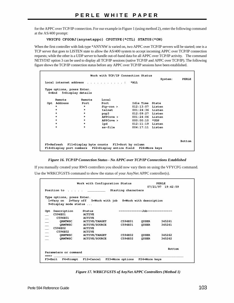
P E R L E W H I T E P A P E R
mand
e is annectionmmandllowing
.
for the APPC over TCP/IP connection. For our example in Figure 1 (using method 2), enter the following comat the AS/400 prompt:
VRYCFG CFGOBJ(anynetappc) CFGTYPE(*CTL) STATUS(*ON)
When the first controller with link type *ANYNW is varied on, two APPC over TCP/IP servers will be started; onTCP server that goes to LISTEN state to allow the AS/400 system to accept incoming APPC over TCP/IP corequests; while the other is a UDP server to handle out-of-band data for all APPC over TCP/IP activity. The coNETSTAT option 3 can be used to display all TCP/IP sessions (native TCP/IP and APPC over TCP/IP). The fofigure shows the TCP/IP connection status before any APPC over TCP/IP sessions have been established.
Figure 16. TCP/IP Connection Status - No APPC over TCP/IP Connections Established
If you manually created your RWS controllers you should now vary them on using the VFYCFG command
Use the WRKCFGSTS command to show the status of your AnyNet APPC controller(s).
Figure 17. WRKCFGSTS of AnyNet APPC Controllers (Method 1)
Work with TCP/IP Connection Status System: PERLE Local internet address . . . . . . . . . . . : *ALL
Type options, press Enter. 4=End 5=Display details
Remote Remote Local Opt Address Port Port Idle Time State * * ftp-con > 012:13:07 Listen * * telnet 001:24:36 Listen * * pop3 012:09:27 Listen * * APPCove > 001:24:06 Listen * * APPCove > 000:00:10 *UDP * * lpd 012:11:19 Listen * * as-file 004:17:11 Listen
Bottom F5=Refresh F11=Display byte counts F13=Sort by column F14=Display port numbers F22=Display entire field F24=More keys
Work with Configuration Status PERLE 07/21/97 19:42:59 Position to . . . . . __________ Starting characters
Type options, press Enter. 1=Vary on 2=Vary off 5=Work with job 8=Work with description 9=Display mode status ...
Opt Description Status -------------Job-------------- __ C594E01 ACTIVE __ C594E01 ACTIVE __ QRMTWSC ACTIVE/TARGET C594E01 QUSER 345261 __ QRMTWSC ACTIVE/SOURCE C594E01 QUSER 345261 __ C594E02 ACTIVE __ C594E02 ACTIVE __ QRMTWSC ACTIVE/TARGET C594E02 QUSER 345262 __ QRMTWSC ACTIVE/SOURCE C594E02 QUSER 345262
Bottom Parameters or command ===> _________________________________________________________________________ F3=Exit F4=Prompt F12=Cancel F23=More options F24=More keys
Perle 594 Reference Guide 103

P E R L E W H I T E P A P E R
y have
Figure 18. WRKCFGSTS of AnyNet APPC Controller (Method 2)
The NETSTAT option 3 displayed in the following figure shows the associated TCP/IP connections after thebeen established with the 594.
Figure 19. TCP/IP Connection Status - 594 TCP/IP Connections Established
Use the WRKCFGSTS to show the status of the remote workstation controllers.
Work with Configuration Status PERLE
07/21/97 19:42:59 Position to . . . . . __________ Starting characters Type options, press Enter. 1=Vary on 2=Vary off 5=Work with job 8=Work with description 9=Display mode status ... Opt Description Status -------------Job-------------- __ ANYNTCTL ACTIVE __ C594E01 ACTIVE __ QRMTWSC ACTIVE/TARGET C594E01 QUSER 345261 __ QRMTWSC ACTIVE/SOURCE C594E01 QUSER 345261 __ C594E02 ACTIVE __ QRMTWSC ACTIVE/TARGET C594E02 QUSER 345262 __ QRMTWSC ACTIVE/SOURCE C594E02 QUSER 345262
Bottom Parameters or command ===> _________________________________________________________________________ F3=Exit F4=Prompt F12=Cancel F23=More options F24=More keys
Work with TCP/IP Connection Status
System: PERLE Local internet address . . . . . . . . . . . : *ALL
Type options, press Enter. 4=End 5=Display details
Remote Remote Local Opt Address Port Port Idle Time State * * ftp-con > 012:13:07 Listen * * telnet 001:24:36 Listen * * pop3 012:09:27 Listen * * APPCove > 001:24:06 Listen * * APPCove > 000:00:10 *UDP * * lpd 012:11:19 Listen * * as-file 004:17:11 Listen 101.102.100.30 APPCove > 1024 000:17:52 Established 101.102.100.30 1025 APPCove > 000:19:22 Established 101.102.100.31 APPCove > 1025 000:19:22 Established 101.102.100.31 1025 APPCove > 001:48:37 Established
Bottom F5=Refresh F11=Display byte counts F13=Sort by column F14=Display port numbers F22=Display entire field F24=More keys
104 Perle 594 Reference Guide

P E R L E W H I T E P A P E R
d router new
l TCP/IPvalue isase, you
his is
ended:
til theff thethat areevice deviceat will
CP/IP status
tion.our linehat therted. To *CTL
TCP/IP
Figure 20. WRKCFGSTS of Remote Work Station Controllers
Performance and Operation ConsiderationsYou may be able to improve your performance with a few simple changes to the AS/400 TCP/IP Interface anconfiguration. Currently the AS/400 system defaults to a Maximum Transmission Unit (MTU) of 576 when aroute is added. This default value is used to ensure packets are not dropped over the route since alimplementations have to support at least a 576-byte transmission unit. However, in many cases this unnecessarily small since there are no intermediate hops that only support a 576-byte packet. If this is the cshould change the MTU from 576 to *IFC. The MTU now defaults to the line description frame size. Tapproximately 2000 for token-ring and 1500 for Ethernet.
If for any reason you wish to bring down one of your 594 TCP/IP controllers, the following procedure is recomm
• Vary off the RWS controller associated with the 594 you wish to bring down. Be sure to wait uncontroller goes completely to a VARY OFF state. Note, it is not recommended that you vary oAnyNet APPC controller since there might be other 594 CP sessions or AnyNet PWS sessions active under the AnyNet APPC controller. It is also not recommended that you vary off the APPC ddescription associated with the 594 controller unless you are going to immediately delete the APPCdescription. If this is done then the AS/400 may autocreate another APPC device description thconflict with the current APPC device description that the 594 is currently using.
• Use the NETSTAT Opt 3 command to display the TCP/IP connections and end (using Opt 4) all Tconnections with the IP address of the controller you just varied off. Refresh the TCP/IP connectionscreen by pressing F5 a couple of times to verify that all these connections have ended.
• If you want to bring the 594 controller back up, then Vary on the RWS controller again.
The APPC controllers defined with LINKTYPE *ANYNW are no longer directly attached to a line descripThis means you will not see the statuses of your AnyNet APPC controllers when you display the status of ydescription. You will however see the status of a TCP/IP network controller and device (category *NET), tAS/400 automatically creates when a TCP/IP interface that is associated with the line description is stadisplay the status of your AnyNet APPC controllers you must use the WRKCFGSTS command specifyingas the type of description.
It is recommended that your AS/400 IPL shut-down and start-up programs be changed to end and start the
Work with Configuration Status PERLE 07/21/97 19:42:59 Position to . . . . . __________ Starting characters
Type options, press Enter. 1=Vary on 2=Vary off 5=Work with job 8=Work with description 9=Display mode status ...
Opt Description Status -------------Job-------------- __ C594E01R ACTIVE __ C594EDSP01 SIGNON DISPLAY __ C594E02R ACTIVE __ C594EDSP02 SIGNON DISPLAY
Bottom Parameters or command ===> _________________________________________________________________________ F3=Exit F4=Prompt F12=Cancel F23=More options F24=More keys
Perle 594 Reference Guide 105
P E R L E W H I T E P A P E R
0 IPL is back up.
earing in
services respectively. This will ensure that all TCP/IP servers have been properly ended before the AS/40performed and will make sure the TCP/IP servers are started before the 594 AnyNet controllers are brought
Copyright and Trademarks
Copyright 1997-1998. All rights reserved, Perle Systems Limited.
Perle, the Perle logo and Perle 594 are registered trademarks of Perle Systems. All other trademarks appthis document are trademarks of their respective companies.
106 Perle 594 Reference Guide

em
n.
n
rle
be e
an l or re
Glossary
594e Connection Number A parameter used to identify the Perle 594e on the communication network.
594e CP Name The Control Point (CP) Name of the 594e.
594e LU Name The Logical Unit (LU) Name of the 594e.
594e Network Name The Network Name of the 594e.
594e SAP The Service Access Point (SAP) of the 594e.
594e SDLCStation Address The SDLC Station Address of the controller used to uniquely identify the controller on an SDLC communication line.
594e Station Address The Station Address of the controller used to uniquely identify the controller on an X.25 communication line.
594e Utility Program A program which runs on a PC and is used to enter configuration data for the Perle 594e. The configuration data is saved in a configuration file. When the PC is online to the Perle 594e, the 594e Utility can also be used to establish and end network links. You can use the 594e Utility Program in either standalone or online mode.
Access Code The international access code of the 594e optionally used for X.21 communications.
Address Call The full telephone number which the Perle 594e must dial to access AS/400 system. This number contains from 4 to 14 characters. Each character can be a number from 0 to 9. Include the network ID or the country code, but do not include access codes.
Adjacent Link Station (ALS)A node in the communication network with which a device communicates. In an SNA subarea network, there are one, or more, intermediate ALSs.
Advanced Program-to-program Communication (APPC) A data communications process that lets AS/400 programs communicate with programs on another systthat has a compatible communications process.
ALS See Adjacent Link Station.
Alternate Keyboard Translations If an Alternate Keyboard Translation is not specified, then the DWS will use the Default Keyboard TranslatioTo use an Alternate Keyboard Translation, the DefaultKeyboard Translation must be a multinational code.
ANSIAmerican National Standards Institute
APPC See Advanced Program-to-program Communication.
APPC Controller Description The AS/400 system has an APPC Controller Descriptiofor each APPN connection to another system. This includes connections to a controller emulated by a Pe594e, and other AS/400 systems.
APPN Advanced Peer-to-Peer Network.
APPN network A network of computers using APPC.
ASCII American National Standard Code for Information Interchange.
ASCII PortThe ASCII Feature Card has eight ports. Each port canconnected to a modem, allowing remote users to makdial-in connections to the AS/400 system. The dial-in connection can be for a single terminal or PC. There calso be a "passthrough" printer attached to the terminaPC, for a total of 16 ASCII devices on each ASCII FeatuCard.
AS/400 Application System 400. A computer in the IBM midrange product line.
Automatic AnswerA feature that allows a station to answer a call on a switched line without operator action.
Perle 594 Reference Guide 107

Glossary
r.
p
ty
red
ns
e
tup
e
a
Automatic CallA feature that allows a station to call another station on a switched line without operator action.
Beacon MessageA repeating message that an adapter sends to indicate a serious network problem.
BIND CommandA type of command in an SNA environment used to start and define the session.
BPSBits per second.
BridgeA mechanism that connects a network to other networks.
Cable-thruA type of cabling system that allows multiple workstation to be connected to a single cable path.
Call CommandA command entered at an NWS to place the 594e in Call mode.
Call Progress Signals (CPS) X.21 signals sent during link establishment that provide status information.
CDSTL Connect Data Set To Line.
CMOS Type of integrated circuit technology used for the internal memory of the 594e.
Communication Interface The physical connection to the Synchronous Communication Card which allows communication with an AS/400 system.
Communication Line A physical link that allows data transmission between workstations and controllers.
Communication Network Hardware and software which allow data transmission between two locations.
Communication Protocol A set of rules which define the orderly transfer of data across a network.
Compatible Mode A mode of operation in which the Perle 594e operates as a SINGLE controller over a single communication line
and is plug-compatible with a single IBM 5494 controlleSee Chapter 2 for more details.
Concurrent Host Attachment A function that allows the 594e to communicate with uto four AS/400s over a single physical link.
Configuration An arrangement of devices in a network. Also, the activiof defining parameters and options for a particular arrangement of devices.
Configuration Data The list of parameters and options that have been enteduring the process of configuration.
Configuration File A computer file in which configuration data is stored.
Configuration Mode The mode of the Perle 594e during which it can be reconfigured. Use Operating mode to establish sessiowith the AS/400.
Controller A device that allows workstations to communicate withan AS/400.
Controller Address An address which uniquely identifies the controller on thcommunication line.
Controller Setup Diskette Use the Perle 594e Controller Setup Diskette during seand installation of the Perle 594e .
Controller Slot The slot in which to install Multisession Controllers, ThSynchronous Communication Card, or 594e Feature Cards.
Controller Software Diskette Use the Perle 594e Controller Software Diskette for normal system operation.
CPS See Call Progress Signals
CPU Central Processing Unit—the main processing unit of computer.
DBCS See Double-Byte Character Set.
DC Direct Call.
108 Perle 594 Reference Guide

Glossary
d ,
e
ts
ns
ng er
.
DCC Data Country Code.
DCE See Data Circuit Terminating Equipment.
Data Circuit-terminating Equipment (DCE)The equipment that provides the signal conversion and coding between the data terminal equipment (DTE) and the line.
Data LinkThe mechanism (hardware and software) used for sending and receiving data.
Data Terminal Equipment (DTE)A device, like the 594e or the host, that is connected to a network.
DelimiterA character used to indicate the beginning and end of a character string.
Device In this guide, device refers to equipment that connects to either the Perle 594e, the AS/400, or the communications network. For example, workstations and printers are individually known to the AS/400 as a device.
Device Description On the AS/400, the Device Description defines the devices (i.e., display device, print device, etc.) that receive or transmit data through the Perle 594e.
Display ScreenThe part of an NWS or PWS that displays information.
DLCI Data link connection identifier
DNIC Data Network Identification Code.
Double Byte Character Set (DBCS) A character set that requires two bytes to represent each character.
DSR Data set ready.
DSU Data Service Unit.
DTE Data Terminal Equipment.
DTR Data Terminal Ready.
DWS Display-only workstation. Currently referred to as an NWS (nonprogrammable workstation).
EBCDIC Extended Binary Coded Decimal Interchange Code.
EIA232 A standard for serial interfaces between computers ancommunication equipment. Formerly known as RS232this standard is officially recognized as EIA232.
ELLC See Enhanced Logical Link Control.
Enhanced Logical Link ControlIn X.25 communication, a type of logical link control.
Enhanced Mode A mode of operation in which the Perle 594e providesadditional features and can operate as MULTIPLE controllers sharing a multipoint communication line. SeChapter 2 for more details.
Ethernet A local area, packet-switched data network mechanismfor communication between computers.
Facility Request CodeA number comprised of one or two digits that represena subscription parameter.
Feature Card A 594e optional hardware component that adds functioto the 594e.
Field A location on a workstation screen where data is displayed or entered.
Frame A transmission of a minimum of 32-bits that is used bySDLC over a communication network.
Frame RelayAn interface standard that provides fast packet-switchiby leaving some of the checking and monitoring to highlevel protocols.
Full Duplex The exchange of data in two directions simultaneously
Gateway A functional unit that connects networks that have different architecture or use different communication protocols.
Perle 594 Reference Guide 109
Glossary
r p
tus
at
of
s
t
a
Half Duplex (HDX) The transmission of data in only one direction at a time.
HDX See Half-duplex
Hexadecimal The base 16 numbering system using characters 0 through 9 and A through F to represent 0 to 9 and 10 to 15.
Hot Key A sequence of keys which allow the user of an NWS to access multisessions.
Hz Hertz.
IEEE Institute of Electrical and Electronics Engineers
Interface Card A computer card that may be installed in the Perle 594e and which provides connectors for the attachment of communication cables.
Internal Storage The internal memory or CMOS of the Perle 594e.
Kb Kilobyte.
Keyboard Code A two-digit code which identifies the keyboard translation being used.
Keyboard Translation The set of symbols used on a keyboard. Each keyboard translation is designed for use in a particular country.
LAN See Local Area Network.
LAN Card In the Perle 594e, the LAN card refers to either a Token-Ring Feature Card or an Ethernet Feature Card used for LAN connections.
LAN Gateway Using the Perle 594e, the LAN Gateway is the functional unit that connects (via Token-Ring or Ethernet) a local area network (LAN) with another network that uses a different architecture or communication protocol.
LCD Liquid Crystal Display.
Leading Pad A single byte which is sent to the modem in order to synchronize it.
Leased Line A communication line which is dedicated to a particuladevice. This line is always available, and no circuit setuprocedures are required.
LED Light Emitting Diode.
Line Description On the AS/400, the Line Description defines the communication protocol by which the AS/400 communicates with the Perle 594e.
Link Management Interface (LMI) For frame-relay networks, the interface that carries stamessages between two points.
LLC See Logical Link Control.
LMI See Link Management Interface
Local Area Network (LAN)Two or more computers that are located on a user's premises within a limited distance of each other and thare connected to each other directly or indirectly.
Logical Channel Identifier A number used to identify a logical channel, consisting a logical channel group number (4 bits) and a logical channel number (8 bits).
Logical Channel The method by which data on an X.25 virtual circuit is routed between two devices. More than one logical channel can be used to maintain separate data streambetween the same two devices.
Logical Link Control (LLC) For X.25, the information included in data packets thaprovides end-to-end link functions to the SNA layers inthe 594e and AS/400 systems.
LU Logical Unit.
Manual Answer A feature that allows a station to answer a call on a switched line but which requires operator action.
Manual Call A feature that allows a station to call another station onswitched line but which requires operator action.
110 Perle 594 Reference Guide
Glossary
e
al
d
rle
sh de
e
ata
s.
C he
s.
MAU Media Access Unit.
Message Codes A three-digit number which appears on the operator panel display and indicates a specific condition or error of the Perle 594e.
Mode Description The Mode Description on the AS/400 controls communications
Modem (Modulator-Demodulator) A device that converts data from a workstation into a signal that can be transmitted over a communications line, and converts the transmitted signal to data for the receiving device.
Multi-Point Line A communication line which can support communication with more than one device at a time.
MultinationalKeyboard Code The code number for a keyboard translation which uses the multinational EBCDIC character set on the AS/400 system.
Network Attribute An individual parameter or option used by the Perle 594e to establish a network link with the AS/400.
Network Information Parameters and options used by the controller to establish a network link with one of the four alternate AS/400 systems.
Network Link Establishment The steps which must be performed in order to establish a communication link between the Perle 594e and the AS/400 system.
Non Return to Zero (NRZ) A type of data encoding.
Non Return to Zero Inverted (NRZI) A type of data encoding.
NRZ See Non Return to Zero.
NRZI See Non Return to Zero Inverted.
Non-programmable Workstation (NWS)Previously known as a DWS (display-only workstation). An NWS is a workstation attached to your AS/400 that
only displays information from the host. It does not havits own CPU and cannot be programmed.
Null The EBCDIC character that represents the hexadecimvalue of 00.
NWS See Nonprogrammable Workstation
NWSConfiguration A method of configuring the Perle 594e from an attacheNWS. The Perle 594e can only be configured for compatible mode using this method of configuration.
Offline The condition that exists when the 594e is not communicating with the host.
Online The condition that exists when the 594e is in communication with the host.
Online Mode When you use the 594e Utility Program online to the Pe594e, you are working directly on the configuration filecontained within the Perle 594e.
Operating Mode The mode of the Perle 594e during which it can establisessions with AS/400 systems. Use Configuration moto reconfigure the Perle 594e.
Packet A well-defined sequence of bytes, including data and control signals, that is transmitted and switched as onunit.
Packet SizeThe maximum number of bytes the user data area of a dpacket can contain.
Packet Switched The transference of data by means of address packet
Passthrough Printer An ASCII printer that receives data through a port on a Por terminal. The data is passed, unchanged, through tPC or terminal.
Permanent Virtual Circuit (PVC) A type of X.25 virtual circuit which is always available for use between the Perle 594e and the AS/400 systemNo call establishment is required.
Perle 594 Reference Guide 111

Glossary
ted
ta
ent
re
lots
e
Physical Interface The physical connector which is used to attach the Perle 594e to the communication network, or directly to the AS/400 system.
Point-to-Point Line A communication line which supports communication between one two devices.
Polling On a multipoint connection or a point-to-point connection, the process whereby data stations are allowed one at a time to transmit.
Port The hardware mechanism that attaches workstations or a network to the 594e.
Primary Session Controller The controller to which an NWS is physically attached.
Programmable Workstation (PWS) A workstation that can communicate with a host but that can also operate independently of the host.
Protocol A set of governing instructions, requests, and responses that constitute a way of controlling data transfer.
PVCSee Permanent Virtual Circuit.
PWS Programmable workstation.
QLLC See Qualified Logical Link Control.
Qualified Logical LInk Control For X.25 communication, a type of logical link control.
Remote Workstation A workstation that is attached to the host through a network.
RS232A standard for serial interfaces between computers and communication equipment. Formerly known as RS232, this standard is officially recognized as EIA232.
RWS See Remote workstation.
RWS Controller Description The RWS Controller Description on the AS/400 contains parameters for nonprogrammable workstations.
SABM See Set Asynchronous Balanced Mode.
SAP See Service Access Point.
SBCS See Single-Byte Character Set.
SDLC See Synchronous Data Link Control.
Service Access Point (SAP)An address used in a system that allows data to be directo the correct remote device.
Set Asynchronous Balanced Mode (SABM) A data link control command used for establishing a dalink connection in asynchronous balanced mode.
SHM Short Hold Mode.
Short Hold Mode (SHM) For X.25, an option that allows a link to remain established only when there is data to transfer.
SIMM Single In-Line Memory Modules.
Single-Byte Character Set (SBCS) A character set which one requires one byte to represeach character.
Slot A physical location in the chassis of the Perle 594e whean Interface Card may be installed.
Slot Number The number assigned to a slot in the Perle 594e. The sare numbered from left to right.
SNA Systems Network Architecture.
SNA SubArea Network A network which allows the Perle 594e to communicatwith an AS/400 system to which the Perle 594e has nodirect communication line.
SRC System Reference Code.
SVC Switched Virtual Circuit.
Switched Virtual Circuit A type of X.25 virtual circuit which requires a link to beestablished before each use.
112 Perle 594 Reference Guide

Glossary
of
n
r
5
Synchronous Data Link Control A method of managing data transfer across a synchronous communication line.
System Reference Code A code which may appear on the operator panel display, or on a workstation screen. The code will identify a specific condition or error with the Perle 594e.
Terminal Equipment through which data enters or leaves a communication network.
Twinaxial Adapter Cable A short cable which allows up to four twinaxial communication lines to a Twinaxial Feature Card.
V.35 cable Used for low-speed communications, this communication cable conforms to the V.35 standard recommended by CCITT.
V Volts.
VAC Volts Alternating Current.
Vary Off To cause a device or line to be unavailable for its normal use.
Vary Off To cause a device or line to be available for its normal use.
Workstation Input/output equipment connected to a mainframe, or computer network, at which an individual displays, enters, or manipulates data. There are two basic typesworkstations:
• a nonprogrammable workstation (NWS)
• a programmable workstation (PWS).
A Twinaxial NWS or a PC connected to the AS/400 areeach known as a workstation.
X.21 A recommendation by CCITT that defines the interfacebetween a DTE and public data networks. Recommendation X.21 also defines procedures for establishing links on switched or leased communicatiolines.
X.21 switched A procedure for establishing communications links ovecircuit-switched communication lines.
X.25 A recommendation by CCITT that defines the interfacebetween a DTE and a packet-switched data network.
X.25 Network Address The address which uniquely defines this DTE to the X.2network.
Perle 594 Reference Guide 113

Glossary
114 Perle 594 Reference Guide
Index
Numerics594
address format .................................................15connection number ..........................................15CP name ..........................................................15Ethernet address ..............................................16IP address ........................................................16LU name .........................................................16network name ..................................................16SAP .................................................................16station address .................................................16
594 SDLC Station Address .....................................16594 SDLC station address .......................................16594 System Password .............................................16594 utility program
installation SRCs .............................................76run time messages ...........................................76
AAccess Code ............................................................17access code ..............................................................17additional parameters ..............................................17address format .........................................................17Adjacent Link Station (ALS) ................................107Advanced Program-to-program Communication .107alternate keyboard translations ...............................17American National Standards Institute .................107APPN network
configuration example ......................................9AS/400
connection number ..........................................18Data Link Connection Identifier (DLCI) ........19Ethernet address ..............................................19IP address ........................................................19LU name .........................................................19network name ..................................................19SAP .................................................................19
AS/400 configuration examplesAS/400 Ethernet attachment .............................7AS/400 token-ring attachment ..........................6SDLC leased .....................................................2SDLC leased through APPN network ..............9SDLC leased through SNA subarea network ...8TCP/IP Ethernet attachment ...........................13TCP/IP token-ring attachment ..................12, 14X.21 switched ...................................................3X.25 permanent .................................................5X.25 switched ...................................................4
ASCIIdefault keyboard translation ............................19display type .....................................................19feature cards ....................................................19
ASCII Port ............................................................107associated group ......................................................19
automatic answer ..................................................107automatic call ........................................................108Automatic Configuration ........................................20
Bbaud rate ..................................................................20beacon message ....................................................108BIND command ....................................................108BPS .......................................................................108bridge ....................................................................108bytes
total number received .....................................35total number transmitted .................................35
Ccable-thru ..............................................................108call command ........................................................108card ID ....................................................................20circuit type ..............................................................20codes
message codes .................................................37system reference codes ...................................39
connection method ..................................................20connection number
AS/400 ............................................................18Connection Type .....................................................20connection type .......................................................20ConnectionMethod .................................................20Continuous Retry ....................................................21continuous retry ......................................................21
DData Circuit-terminating Equipment (DCE) .........109Data Encoding ........................................................21data encoding ..........................................................21data link ................................................................109Data Link Connection Identifier (DLCI) ................21Data Terminal Equipment (DTE) .........................109default controller address ........................................21Default Keyboard Translation ................................22default keyboard translation ...................................22Default Local Network Name .................................23default local network name .....................................23Default Mode Name ...............................................23default mode name ..................................................23Delay between Retries ............................................23delay between retries ..............................................23delimiter ................................................................109Diagnostic Code Format .........................................23Dial Digit Format ....................................................23dial digit format ......................................................23Direct Call Support .................................................23direct call support ...................................................23display screen ........................................................109
Perle 594 Reference Guide 115

DLCI .......................................................................24
Eenable
inactivity time limit .........................................24passthrough printer .........................................24reconnect time limit ........................................24
enhanced logical link control ................................109errors
594 utility runtime messages ..........................76message codes .................................................37SRCs ...............................................................39
Ethernetaddress ............................................................24address format .................................................85AS/400 attachment configuration example .......7frame format ...................................................24
Ffacility request code ..............................................109FCS Error Count .....................................................25Flow Control ...........................................................25Flow Control Negotiation .......................................25Frame Relay
Communication SRCs .....................................68configuration example ..............................10, 11definition .......................................................109
frame relay token-ring bridgingSRC's ...............................................................69
framesaborted ............................................................17misaddressed ...................................................28number of filtered ...........................................29number received in error .................................29number received with BECN ..........................30number received with DE ...............................30number received with FECN ..........................30total number received ......................................36total number transmitted .................................36
Full Inquiry Interval ................................................25
Ggateway
IP address ........................................................21
Hhardware error SRCs ...............................................75
IInactive Timer (Ti) ..................................................25Inactivity Time Limit ..............................................25
enabling ...........................................................23
Kkeyboard translation
alternate keyboard translation .........................17default keyboard translation ............................22
LLAN Link Station Status
Gateway ..........................................................26Upstream .........................................................26
LCDmessage formats ........................................37, 39
linefacility .............................................................26speed ...............................................................26type .................................................................26
Link Initiation .........................................................26Link State/LLC State ..............................................26Link Window Size ..................................................27link window size .....................................................27LMI
protocol error count ........................................27sequence error count .......................................27timeout count ..................................................27
Local Area Network (LAN)definition .......................................................110
Local Loopback ......................................................27logical channel ........................................................27Logical Link Control ..............................................27logical link control ..................................................27LU name
594 ..................................................................16AS/400 ............................................................19
MManual Options ......................................................27maximum in (N3) ...................................................28Maximum Out (TW) ...............................................28maximum out (TW) ................................................28message codes .........................................................37Mode Name ............................................................28mode name ..............................................................28
default mode name ..........................................23modem ....................................................................28
initialization string ..........................................28Multisession Assignment ........................................29multisession assignment .........................................29
Nnetwork mask ..........................................................29network name
594 ..................................................................16AS/400 ............................................................19default local network name .............................23
Network Subscription .............................................29No Receive Buffers .................................................29number of Multisession Controllers .......................30number of multisession controllers .........................30Number of Retries ...................................................30number of retries .....................................................30number of times T1 timer expired ..........................30NWS
definition .......................................................111
116 Perle 594 Reference Guide
Ooverruns ..................................................................30
Ppacket level sequence numbering ...........................30packet size ...............................................................30
definition .......................................................111Packet Window Size ...............................................30packet window size .................................................30parity .......................................................................30passthrough ASCII printer type ..............................31passthrough printer
emulation ........................................................31enabling ...........................................................24
password .................................................................31Connect Password ...........................................20X.25 password ................................................31
PMCTS error count ..............................................31DSR errot count ..............................................31
Polling Interval .......................................................31port
ASCII ............................................................107printer field .............................................................31printer port and station ............................................31printing configuration .............................................31PVC
circuit type ......................................................20definition .......................................................112
PVC AUTO circuit type .........................................20
RReceiver Acknowledgment Timer (T2) ..................31receiver acknowledgment timer (T2) ......................31reconnect time limit ................................................32
enabling ...........................................................24residue errors ...........................................................32Response Timer (T1) ..............................................32response timer (T1) .................................................32retry
count (N2) .......................................................32counter ............................................................32interval ............................................................33optional call progress signals ..........................33
Reverse Charging ....................................................33
SSAP .........................................................................33
AS/400 ............................................................19definition .......................................................112
SDLC leasedconfiguration example ..............................2, 8, 9
Seconds Between Retries ........................................34seconds between retries ..........................................34select
alternate language at connect ..........................34group at connect ..............................................34
Send Leading Pad ...................................................34
send leading pad .....................................................34Serial Number .........................................................34serial number ..........................................................34Slot ..........................................................................35SNA subarea network
configuration example ......................................8software error SRCs ................................................75SRCs .......................................................................39
1100001100FF ................................................461200001200FF ................................................4818yyzz .............................................................4918yyzz1Ayyzz ................................................52300000 - 600000 .............................................58594 utility program .........................................76FR-TR bridging ..............................................69TCP/IP ......................................................72, 73X.21 switched .................................................54X.25 ................................................................46
station address594 ..................................................................16
subnet mask ............................................................29SVC
circuit type ......................................................20SVCIN circuit type .................................................20system reference codes
SRCs ...............................................................39
TTCP/IP
configuration example ........................12, 13, 14SRCs .........................................................72, 73
Telenet-Type Network Attachment ........................35Token-Ring
address ............................................................35converting address formats .............................85pair conversion table .......................................86
token-ringAS/400 attachment configuration example ......6
Uunderruns ................................................................36
XX.21
configuration example ......................................3switched SRCs ................................................54
X.25configuration example ..................................4, 5SRCs ...............................................................46
Perle 594 Reference Guide 117


