downtown ferry redevelopment
TRANSCRIPT

REPORT
Downtown Ferry Redevelopment
Infrastructure Services Assessment
Prepared for
Auckland Transport
Prepared by
Tonkin & Taylor Ltd Date
November 2018 Job Number
1004393.1000.v2

Document Control
Title: Downtown Ferry Redevelopment, Infrastructure Services Assessment
Date Version Description Prepared by: Reviewed by: Authorised by:
29/10/18 1 For Issue K Rigter / K Johnson
A Richardson / T Allsopp-Smith
R Reinen-Hamill
14/11/18 2 Updated to RC drawings K Johnson A Richardson A Richardson / T Allsopp-Smith
R Reinen-Hamill
Distribution:
Auckland Transport 1 copy
Tonkin & Taylor Ltd (FILE) 1 copy

Tonkin & Taylor Ltd Downtown Ferry Redevelopment - Infrastructure Services Assessment Auckland Transport
November 2018 Job No: 1004393.1000.v2
Table of contents
1 Introduction 1
2 Existing site description and layout 1
3 Proposed development 2
4 Stormwater 3
5 Wastewater 4 5.1 Existing Infrastructure 4
5.1.1 Current wastewater generation 4 5.2 Proposed infrastructure 5 5.3 Changes in wastewater generation 6
5.3.1 Downstream capacity utilisation 6 6 Water supply 7
6.1 Existing Infrastructure 7 6.2 Proposed Infrastructure 7 6.3 Changes in Water Supply demand 8 6.4 Firefighting requirements 8
7 Other services and proposed service corridor 9
8 Conclusions 9
9 Applicability 10

1
Tonkin & Taylor Ltd Downtown Ferry Redevelopment - Infrastructure Services Assessment Auckland Transport
November 2018 Job No: 1004393.1000.v2
1 Introduction
Auckland Transport (AT) has engaged Tonkin & Taylor Ltd (T+T) to undertake the civil design for the relocation of Pier 3 and Pier 4 ferry terminals in Auckland City Ferry Basin to the west side of Queens Wharf and proposed modifications to the existing ferry terminal building.
The purpose of this report is to assess the adequacy of the existing infrastructure for stormwater, sanitary sewer, water supply, and services (data, power, and communications) and describe the proposed changes to the existing infrastructure to support the proposed development.
We have completed the Resource Consent design of the proposed services, which includes sanitary sewer, stormwater, water supply and other services, however it is intended that a detailed design of the proposed infrastructure will follow at a later date which will be used to lodge other applicable consent applications including Building Consent.
2 Existing site description and layout The subject site is located on Queens Wharf, Downtown Auckland adjacent to the Waitematā Harbour. The existing Downtown Ferry Terminal (DFT) is located on Queens Wharf itself (as shown in Figure 2-1 below). Queens Wharf is relatively flat, with a deck level of approximately RL3.0 m, and being approximately 375 m long by 88 m wide, having an overall site area of 3 Ha.
Figure 2-1: Existing Site layout
Queens Wharf also houses two existing event facilities; The Cloud and Shed 10, which are used at various times for public and private functions. Furthermore, the east of Queens Wharf is used for mooring larger Cruise ships, with passenger disembarking into Downtown and onto busses and a Taxi rank from the wharf located outside the existing ferry terminal adjacent to Quay Street. An existing container village and open spaces are also located here.

2
Tonkin & Taylor Ltd Downtown Ferry Redevelopment - Infrastructure Services Assessment Auckland Transport
November 2018 Job No: 1004393.1000.v2
The Existing Terminal and Pier 1, see Figure 2-2, houses ticket offices; waiting areas and several existing public and staff toilets; complete with showers and wash basins. These are serviced by existing water, wastewater and electrical installations throughout the terminal, which also includes existing wastewater (sullage) tanks used by the ferries operating out of the terminal. Sullage from these operations connects to existing sewage tank prior to discharge into the public sewer systems on Quay Street based on existing service plans prepared by GHD.
Figure 2-2: Existing Ferry Terminal Building (Pier 1) layout
Mapping of the existing services was undertaken by GHD in April 2018 and includes the Ferry Terminal and Pier 1. These plans of existing services at the southern end of Queens Wharf are attached in Appendix A and illustrate the known arrangements of water connections, sullage tanks and dry services.
3 Proposed development
As part of the Downtown Ferry terminal (DFT) redevelopment six new berths, will be located along the western edge of Queens Wharf, to the north of the existing Ferry Terminal/ Pier 1 (as shown in Figure 3-1 below). Three new gangways will connect the six berths to Queens Wharf. The proposed development layout and details are attached in Appendix B, however a general overview of the layout is included in Figure 3-1 below.

3
Tonkin & Taylor Ltd Downtown Ferry Redevelopment - Infrastructure Services Assessment Auckland Transport
November 2018 Job No: 1004393.1000.v2
Figure 3-1: Proposed location of new berths along Queens Wharf
The proposed changes to the existing infrastructure include new services to these new berths including potable water supply and a new standalone sullage system with connections back to the existing reticulation on Quay Street. Overall, as the new berths are to replace existing berths (Pier 3 and 4) and retain the existing ferry capacity; the overall net increase in wastewater will be minimal and is described in more detail in the following sections.
Further changes are proposed to the terminal building infrastructure on Pier 1; these currently include a nominal but relatively small increase in numbers of public toilets and hand basin facilities. These arrangements and details are still being developed but it is envisaged these will connect onto the existing private systems within the terminal. No significant or major changes are envisaged to the existing network.
These additional facilities will have a small net increase in the overall wastewater generation and water demand but not significant in the context of the current upstream Downtown CBD environment. Calculations on the proposed increase in wastewater and water supply detailed further in sections 5 and 6 below. This will be reviewed with Watercare prior to detailed design and where connections involve changes or additions to the private system these will be covered under separate Building Consent application.
4 Stormwater
As described in the previous sections the existing Queens Wharf super-structure will be retained, therefore there will be no impact on the impervious area from either the Wharf or the ferry terminal/ Pier 1 buildings and therefore there will be no change in run off as a result.
Proposed arrangements include for the new pontoons, gangways and associated shelter areas on Queens Warf West (as was shown in Figure 3-1); however runoff will not be captured nor treated
Proposed new berths
4
Tonkin & Taylor Ltd Downtown Ferry Redevelopment - Infrastructure Services Assessment Auckland Transport
November 2018 Job No: 1004393.1000.v2
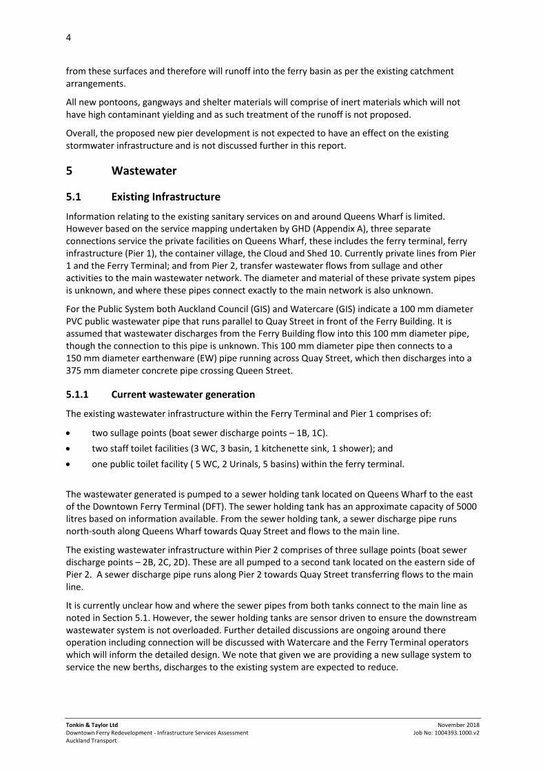
from these surfaces and therefore will runoff into the ferry basin as per the existing catchment arrangements.
All new pontoons, gangways and shelter materials will comprise of inert materials which will not have high contaminant yielding and as such treatment of the runoff is not proposed.
Overall, the proposed new pier development is not expected to have an effect on the existing stormwater infrastructure and is not discussed further in this report.
5 Wastewater
5.1 Existing Infrastructure
Information relating to the existing sanitary services on and around Queens Wharf is limited. However based on the service mapping undertaken by GHD (Appendix A), three separate connections service the private facilities on Queens Wharf, these includes the ferry terminal, ferry infrastructure (Pier 1), the container village, the Cloud and Shed 10. Currently private lines from Pier 1 and the Ferry Terminal; and from Pier 2, transfer wastewater flows from sullage and other activities to the main wastewater network. The diameter and material of these private system pipes is unknown, and where these pipes connect exactly to the main network is also unknown.
For the Public System both Auckland Council (GIS) and Watercare (GIS) indicate a 100 mm diameter PVC public wastewater pipe that runs parallel to Quay Street in front of the Ferry Building. It is assumed that wastewater discharges from the Ferry Building flow into this 100 mm diameter pipe, though the connection to this pipe is unknown. This 100 mm diameter pipe then connects to a 150 mm diameter earthenware (EW) pipe running across Quay Street, which then discharges into a 375 mm diameter concrete pipe crossing Queen Street.
5.1.1 Current wastewater generation
The existing wastewater infrastructure within the Ferry Terminal and Pier 1 comprises of:
two sullage points (boat sewer discharge points – 1B, 1C). two staff toilet facilities (3 WC, 3 basin, 1 kitchenette sink, 1 shower); and one public toilet facility ( 5 WC, 2 Urinals, 5 basins) within the ferry terminal. The wastewater generated is pumped to a sewer holding tank located on Queens Wharf to the east of the Downtown Ferry Terminal (DFT). The sewer holding tank has an approximate capacity of 5000 litres based on information available. From the sewer holding tank, a sewer discharge pipe runs north-south along Queens Wharf towards Quay Street and flows to the main line.
The existing wastewater infrastructure within Pier 2 comprises of three sullage points (boat sewer discharge points – 2B, 2C, 2D). These are all pumped to a second tank located on the eastern side of Pier 2. A sewer discharge pipe runs along Pier 2 towards Quay Street transferring flows to the main line.
It is currently unclear how and where the sewer pipes from both tanks connect to the main line as noted in Section 5.1. However, the sewer holding tanks are sensor driven to ensure the downstream wastewater system is not overloaded. Further detailed discussions are ongoing around there operation including connection will be discussed with Watercare and the Ferry Terminal operators which will inform the detailed design. We note that given we are providing a new sullage system to service the new berths, discharges to the existing system are expected to reduce.

5
Tonkin & Taylor Ltd Downtown Ferry Redevelopment - Infrastructure Services Assessment Auckland Transport
November 2018 Job No: 1004393.1000.v2
Flows from the current toilet blocks from the Ferry Terminal have been estimated based on a passenger count undertaken by T+T between 24 and 25 October 2018 during peak hours. The assessment assumes a non-peak hour use of 50% of the peak hour use, at a 10 L usage per person.
The flows from the existing sullage tanks have been estimated based on our conversations with Fullers and the AT operational team. As an initial estimate, we have conservatively assumed that each tank is emptied 6 times per day for the basis of our analysis.
Wastewater from The Cloud and Shed 10 discharge to the same public network pipes, however they will not be affected by our proposals for the DFT. A survey of the services from these buildings was not undertaken and details of wastewater is also uncertain. Based on the limited information, we have not calculated for any wastewater generation from these two buildings specifically; however we have taken consideration of wastewater discharges from the Queens Wharf in general through the terminal usage and conservative estimates, assumptions will be reviewed with Watercare to identify any issue or constraints that arise with respect to Shed 10 and The Cloud on the DFT proposals.
Other sources of upstream wastewater generation include the CBD buildings and properties, which contribute to the wastewater collected by the downstream 375 mm diameter concrete pipe crossing Queen Street. The flows from upstream CBD buildings have been estimated following the design approach outlined in the Watercare Water and Wastewater Code of Practice for Land Development1 and wastewater flows have been estimated based on the total floor area of each structure assuming “office and dry retail use”. Diagrams are provided in Appendix C of the existing catchments considered upstream of the main connections at Queens Wharf into which all DFT and Queens Wharf discharge into.
This is considered to be a conservative estimate of the actual wastewater upstream as some of the buildings in the catchment area will be classified in-use as hotels or other uses. Having reviewed the sensitivity to this assumption we have concluded this would generally generate less wastewater per m2 than calculated therefore we have detailed a conservative estimate based on the limited information available for those reasons given above.
5.2 Proposed infrastructure
As part of the new berths along Queens Wharf West the berths will be serviced by three new sullage points. It is intended that similar arrangements to the existing sullage operations from Pier 1 using a dedicated sullage discharge tank and new connection to the public reticulation will be provided for the new berths to minimise and mitigate the impact on the existing private infrastructure. A new pump system will be required to connect the sullage points to the tank along the approximately 300 m distance from the furthest berth to the holding tank. The location of proposed sullage points and pipes are shown on Dwg, 1004393.1000-RC109 in Appendix B. This will be confirmed at detailed design.
This tank will then connect to the public system in a similar arrangement to the existing. The exact details and connections are still being developed and will be discussed and resolved in coordination with Watercare.
Proposals include for new wastewater facilities within the ferry terminal these include an additional 7 No. WC, 7 No. basins, 1 No. shower and 2 No. commercial kitchen sinks. These will require some modification to existing system but largely represent an increase in connections onto the existing private system arrangements within the ferry terminal only.
1 Watercare. The Auckland Code of Practice for Land Development and Subdivision. Water and Wastewater Code of Practice for Land Development and Subdivision. Chapter 5: Wastewater. Ver 2.1.

6
Tonkin & Taylor Ltd Downtown Ferry Redevelopment - Infrastructure Services Assessment Auckland Transport
November 2018 Job No: 1004393.1000.v2
No other changes in the infrastructure impact on the wastewater generation.
5.3 Changes in wastewater generation
The follow is concluded with respect to new wastewater generation:-
There is no expected increase in the wastewater generated by the new sullage points, as currently there is no proposed increase to the number of ferries in service. Therefore, the wastewater generated from the current number of ferry services per day is considered to be the same pre- and post- development.
As for the Ferry Terminal redevelopment the additional public toilets and staff facilities will increase the net change in wastewater generation. This approximately doubles the current amount of toilet and basin systems from the existing. We have therefore estimated that the wastewater generation from these facilities is also doubled.
The results of the wastewater assessment are presented in Table 5-1 below.
These Pre- and post- development wastewater flows vary day to day given variations in the number of persons using the facilities, however we will be refining these estimates at later stages following further discussions with Watercare. Full wastewater calculations and diagrams of catchment areas used in determining these figures are attached in Appendix C.
Table 5-1: Estimated pre and post-development wastewater flows
Unit Pre-development (Upstream CBD contribution)
Pre-development
(Piers 1 and 2 contribution)
Estimated post-development increase
(From additional toilets and public staff/amenities)
Average daily demand
m3/day 1465 82 4.2
l/s 17 0.9 0.05
Peak daily flow l/s 84.7 5.9 0.3
The contribution from the net increase in wastewater generation is expected to be a change of 0.3% of the pre development. Overall, this is a minimal increase to the expected wastewater generation as detailed above because of the small numbers of additional amenities involved when compared with the more significant upstream CBD contributions.
It is therefore estimated that the changes in the new wastewater generation from the DFT redevelopment taking into account the sensitivity of the total wastewater generation is considered minimal.
5.3.1 Downstream capacity utilisation
The downstream pipe capacity of the 375 mm EW pipe has been estimated to be approximately 96 l/s. From the analysis of the wastewater network, the contribution from the upstream CBD buildings is expected to not change and therefore maintains an estimated utilisation of 88.2 % of the capacity of this line. As noted above the overall usage including the post development ferry terminal increase is expected to increase the utilisation from 94.3% be 94.6% as shown in Table 5-2.
Based on the expected current contributions and future changes it is not expected that the capacity of the 375 mm EW pipe will be exceeded.

7
Tonkin & Taylor Ltd Downtown Ferry Redevelopment - Infrastructure Services Assessment Auckland Transport
November 2018 Job No: 1004393.1000.v2
Table 5-2: Capacity Utilisation of 375 mm diameter wastewater line
Unit
Upstream CBD contribution
Piers 1 and 2 contribution + Toilets
Total Capacity Used
Pre-development capacity used % 88.2 6.1 94.3
Post-development capacity used % 88.2 6.4 94.6
There may be downstream capacity issues with the 400 mm pipe which connects downstream of the 375 mm pipe, as the lesser slope gradient indicates a slightly lower capacity and therefore a possible slightly higher utilisation (<98%). However, as the values presented in this report are conservative and net increases are minimal, it may not be an actual constraint. This is currently being discussed and coordinated with Watercare to ensure existing issues are not a concern and refine the existing utilisations estimates, where appropriate.
Based on our current estimate, the analysis indicates that the existing public wastewater network in the direct vicinity of the development is likely to have sufficient capacity to accommodate the proposed development.
The intention will be for this report to be updated once further refinement of estimated volumes and discharges have been undertaken with Watercare.
6 Water supply
6.1 Existing Infrastructure
As described above in Section 2 the existing Queens Wharf area consist of existing event facilities and the existing ferry terminal, these are currently serviced facilities and are therefore assumed to be compliant to the requirements of Watercare water supply2.
Auckland Council GIS indicates a 150 mm and 200 mm diameter CI water main running along the northern side of Quay Street. It is assumed that all water to Queens Wharf, Piers 1 and 2 and the ferry building are obtained from this line. A water meter is located at both the east and west side of the ferry building.
Two public fire hydrants are in close proximity to the entrance to the site along Quay Street and a further three private fire hydrant have been located based on a site walkout located along Queens Wharf West.
The location of existing water mains and fire hydrants are shown on the Watercare services plan attached in Appendix D.
6.2 Proposed Infrastructure
The current, pre-development water demand includes all water demand to Pier 1, Pier 2, the Ferry Building and the Ferry Terminal. The Cloud and Shed 10 buildings are also likely serviced by the same 150 mm CI pipe along north side of Quay Street.
Additional new water supply points will be provided to each of the new six berths along Queens Wharf West (via one new proposed connection to the public reticulation) however as described
2 Watercare Standards specify a minimum supply pressure of 250kPa at the supply point.

8
Tonkin & Taylor Ltd Downtown Ferry Redevelopment - Infrastructure Services Assessment Auckland Transport
November 2018 Job No: 1004393.1000.v2
previously with respect to no expected net change in sullage as a result of no expected increase in ferry services, a similar conclusion is taken on the supply of new water at these berths.
The post-development demand is however expected to increase due to the additional public/staff toilets and amenities only within the ferry terminal, in line with those new amenities mentioned previously in Section 5.2.
6.3 Changes in Water Supply demand
Water demand for the pre and post development cases have been estimated based on the estimated wastewater generation values. Due to the nature of this development, we have assumed that wastewater flow generated within the subject site constitutes 90% of the total water demand.
The estimated pre and post development water demand is summarised in Table 6-1 below:
Table 6-1: Estimated pre and post-development water flows
Unit Pre-development Post development
Average daily demand m3/day 91 96
l/s 1 1.1
Peak daily demand l/s 6.7 6.9
Therefore, as the relative net increase in wastewater generation as described in Section 5.3 was low the net water use demand increase is expected to be minimal also.
6.4 Firefighting requirements
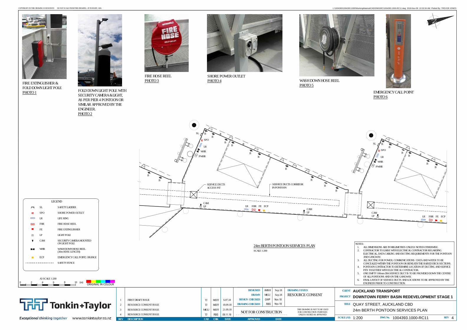
The proposed design includes a fire hose reels at each berth (six total) in addition to the water supply points mentioned above. These will be serviced from the same water connection.
As detailed above two public fire hydrants are located on Quay Street within approximately 200 to 375 m from the new berths as identified on the Auckland Council GIS. However a further three private fire hydrants are located along Queens Wharf alongside the proposed berths, and would be proposed to be used for firefighting requirements.
A specific fire-fighting assessment will need to be undertaken to determine the fire-fighting water supply requirements for the development and the appointment of a fire specialist is underway and confirm the fire hydrant use above.
Hydrant flow testing has not been undertaken and will be undertaken as part of a site specific fire-fighting assessment to confirm the design of the system and identify any capacity constraints in the town supply to meet the firefighting water supply requirements for the development. However, as the increase is water demand is expected to be limited to 0.3 l/s or 18 l/min, it is likely that the existing public supply can adequately supply the estimated peak daily demand of 6.9 L/s from the proposed development. Should it be found that the existing pressure is less than required, booster pumps maybe required.
Furthermore as the existing infrastructure around Queens Wharf houses the two large event facilities there is a valid assumption that the existing is already compliant and therefore should not result in any major issues for the new proposals.
Overall, as the site is located in the CBD, we consider that the current water supply infrastructure will be able to provide the required capacity without the need for additional booster pumps. However, this will be subject to confirmation with the Fire Specialist and Watercare with respect to a compliant detailed design.
9
Tonkin & Taylor Ltd Downtown Ferry Redevelopment - Infrastructure Services Assessment Auckland Transport
November 2018 Job No: 1004393.1000.v2
7 Other services and proposed service corridor
Dry services such as power, CCTV and communications, as well as the wastewater, fire main and water lines will connect with the existing services and to the existing distribution room. A services corridor will carry the services to the proposed new ferry berths.
The location of the proposed service corridors is shown on the Dwg. 1004393.1000-RC108 and 109 attached in Appendix B.
8 Conclusions
Based on our initial infrastructure assessment, we consider the following:
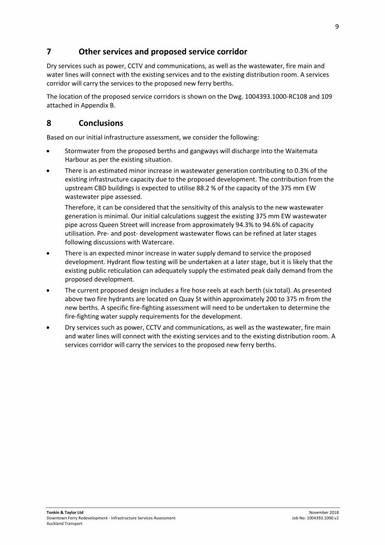
Stormwater from the proposed berths and gangways will discharge into the Waitemata Harbour as per the existing situation.
There is an estimated minor increase in wastewater generation contributing to 0.3% of the existing infrastructure capacity due to the proposed development. The contribution from the upstream CBD buildings is expected to utilise 88.2 % of the capacity of the 375 mm EW wastewater pipe assessed. Therefore, it can be considered that the sensitivity of this analysis to the new wastewater generation is minimal. Our initial calculations suggest the existing 375 mm EW wastewater pipe across Queen Street will increase from approximately 94.3% to 94.6% of capacity utilisation. Pre- and post- development wastewater flows can be refined at later stages following discussions with Watercare.
There is an expected minor increase in water supply demand to service the proposed development. Hydrant flow testing will be undertaken at a later stage, but it is likely that the existing public reticulation can adequately supply the estimated peak daily demand from the proposed development.
The current proposed design includes a fire hose reels at each berth (six total). As presented above two fire hydrants are located on Quay St within approximately 200 to 375 m from the new berths. A specific fire-fighting assessment will need to be undertaken to determine the fire-fighting water supply requirements for the development.
Dry services such as power, CCTV and communications, as well as the wastewater, fire main and water lines will connect with the existing services and to the existing distribution room. A services corridor will carry the services to the proposed new ferry berths.

10
Tonkin & Taylor Ltd Downtown Ferry Redevelopment - Infrastructure Services Assessment Auckland Transport
November 2018 Job No: 1004393.1000.v2
9 Applicability
This report has been prepared for the exclusive use of our client Auckland Transport, with respect to the particular brief given to us and it may not be relied upon in other contexts or for any other purpose, or by any person other than our client, without our prior written agreement.
Tonkin & Taylor Ltd
Report prepared by: Report reviewed by:
.......................................................... ...........................….......…...............
Katie Rigter / Kevin Johnson A Richardson / Tim Allsopp-Smith Civil Engineer Senior Civil Engineer
Authorised for Tonkin & Taylor Ltd by:
..........................................................
Richard Reinen-Hamill Project Director
KRIG \\ttgroup.local\files\aklprojects\1004393\1004393.1000 - pier 3 and 4 relocation\issueddocuments\infrastructure services assessment\20181016_krig_infrastructure assessment report v2 for issue .docx

Appendix A : Services Plan
GHD (April 2018) – Quay Street Services Mapping. Dwg. 51-3768157-C001, -011, -012, -012A, -013, -014.

M
H
M
M
V
F
F
V
V
T
T
T
F M
T
TT
XX
X
X
V
XX
X
X
X
N
W
W
WWWW WWW
W WW
W W W W
W
W
W
W
W W
W
W
W
W W W
W W
W
WW
WW WW WW WW WW
WWWW WW
WW
WWWW WW WW WW
WWWW WW
WW
WW
WW
WW WWWWWW
WW WW WW WWWW
WW
SW
SW
SWSW
SWSW
SWSW
SW
SW SW
SW
SW
SW SW SW
SW
SWSWSWSWSWSW
SWSW
SW
SW
C
C CC C C C
C C C C C C C
C C C C C
C CC
C C C C C C C
C C
C C C C
CC C
C
C C C
CC
C C C CC
C
C C C C CC C C
C
E E EE E
G GVF VF
VF VF VF VF VF
VF VF VF VF
VF
VFVF
G G
G
G
G
G
GE
E E E
E E
E
E EE
E
E
E
E
E
E E
E
E
E
E
E
E
EE
EE
EE
EE
EE
C C C C C
C C C CC C C CC C C
C C C C C
C C CC C C
C C C C C C
C C C CC C C
C C C C C C C C
C C
C
E E E E E E
E E E E E E E E
E E E E E E E E E E
E E E E EE E E E E E E E E
E E E E E E
E E E E E E
G G G G G G G G G G G G GVF VF VF
10
9
8
7
14
13
12
11
18
17
15
16
19
20
21
22
3940
4142
4344
This Drawing must not be
used for Construction unless
signed as Approved
Date
Check
Drafting
DateDrawnRevisionNo
A1
Rev:Drawing No:
Original Size
Title
Project
Client
Check
DesignerDrawn
Scale
Design
Conditions of Use.
This document may only be used by
GHD's client (and any other person who
GHD has agreed can use this document)
for the purpose for which it was prepared
and must not be used by any other
person or for any other purpose.
DO NOT SCALE
Note: * indicates signatures on original issue of drawing or last revision of drawing
GHD Limited
Level 3, GHD Centre
27 Napier Street, Freemans Bay, Auckland 1011 New Zealand
T 64 9 370 8000 F 64 9 370 8001
E [email protected] W www.ghd.com
Plot Date: Cad File No:19 April 2018 - 1:36 p.m. \\ghdnet\ghd\NZ\Auckland\Projects\51\37681\CADD\Drawings\51-3768157-C001_C011-C014.dwg
Plotted by:
Daniel Xie
(Project Director)
Approved
Job
Manager
Project
Director
PRELIMINARY
AUCKLAND TRANSPORT
QUAY STREET SERVICES MAPPING
OVERALL LAYOUT PLAN
51-3768157-C001
A
AS SHOWN
REFER 51-3768157-C011REFER 51-3768157-C012 REFER 51-3768157-C013
REFER 51-3768157-C014
REFER 51-3768157-C012A
0 2 8 10m64
SCALE 1:200 AT ORIGINAL SIZE

M
M
M
V
F
F
VT
X
51 52
53
54
5556
N
109-111
109
111
109
117
188
560 (Abandoned) WWWWWWWW
W
W
W200 C
LS
150 A
C
100 C
LS
W W W W W W W W
W W W W W
W W W W
150 AC
W
W W W W W W W W W W W
150 (A
bandon
ed)
WW
225 AC
225 A
C
225 A
C
WW
WW
225 ACWW WW WW
WW
WW
WW
150 E
W15
0 CLC
IW
WW
W
WW
WW WW WW WW WW WW
WW WW WW WW
WW
WW
WW
WW
WW
WW
WW
225 A
CW
W
225 AC
WW
WW
WW
WW
WW WW WW WW WW WW
225 ACWW WW WW WW WW WW WW WW
Abandoned
SW
SW
SW SW SW
SWSWSW
SWSW
110 PYVN
225 ERWR
SW
1000
SWSW
SWSW
SWSW
SW
SW
SW
SW
SW
SW
SWSW
SWSW
SW
SW
225
SW
C C C C C
C C C C C C CC C C C C C C C C C C C C C C C C C C C C
C C C C C C C C C C C C C C C C C C C C C C C C C C C
C
CC
C C C CC C C C C C C C C C C
C C C C
C C C C C C C
C
CC
CC
CC
CC
C C C C C C C C C C C C C
C C C C C C C C C C C CC C C C C C C C C C C
CC
C
C
C
CC
C
CC
C
C
C
C
C
C
C C C C C C C C C
C
C
C
C
C
C
C
C C C C C C C C C
VF VF VF VF VF VF VF VF VF VF VF VF VF VF VF
VFVF
VFVF
VFVF
VF VF VF VF VF VF VF VF VF VF VFVF VF VF VF
G G G G G G G G
GG
GG
GG
G G G G
E E
E E E E E E
E E E
E
E
E
E
E
E
E
E
EE
E
E
E
E
E
E E E EE
EE
E E E E E
EE
EE
EE
EE
E
E E E E E E E E
E
E E E E
EE
EE
E
E E E
QUAY STREET
LOW
ER A
LBER
T ST
REET
PIER 4
PIER 3 PIER 2
10
9
8
7
14
13
12
11
18
17
15
16
19
20
21
22
3940
4142
4344
F6A
108
107106
105
104
103102
125
109
110
111
112
113
93
94
95
96
97
98
124
123
120
92
89
101
SEWER DISCHARGE PIPE TO CUSTOMSSTREET AND QUEEN STREET HOLDINGTANK (WATERCARE)?
WATERMAIN
WATERMAIN POSSIBLE FEEDFOR PIER 1
WATERMAIN
WATERMAIN
This Drawing must not be
used for Construction unless
signed as Approved
Date
Check
Drafting
DateDrawnRevisionNo
A1
Rev:Drawing No:
Original Size
Title
Project
Client
Check
DesignerDrawn
Scale
Design
Conditions of Use.
This document may only be used by
GHD's client (and any other person who
GHD has agreed can use this document)
for the purpose for which it was prepared
and must not be used by any other
person or for any other purpose.
DO NOT SCALE
Note: * indicates signatures on original issue of drawing or last revision of drawing
GHD Limited
Level 3, GHD Centre
27 Napier Street, Freemans Bay, Auckland 1011 New Zealand
T 64 9 370 8000 F 64 9 370 8001
E [email protected] W www.ghd.com
Plot Date: Cad File No:19 April 2018 - 1:36 p.m. \\ghdnet\ghd\NZ\Auckland\Projects\51\37681\CADD\Drawings\51-3768157-C001_C011-C014.dwg
Plotted by:
Daniel Xie
(Project Director)
Approved
Job
Manager
Project
Director
PRELIMINARY
AUCKLAND TRANSPORT
QUAY STREET SERVICES MAPPING
PLAN 1
51-3768157-C011
A
D XIE
1:200
VF VF
LEGEND
SWSTORMWATERSEWERWATER
SW MANHOLESS MANHOLE
EXISTING SERVICES ON ROAD
W W
E E
G G
WATERMAINCATCHPIT
TELECOM
ELECTRICITYGAS
VODAFONE
WW
C CCOMMUNICATION
POWER POLE
FO FOFIBRE OPTIC
STREET LIGHTELECTRICITY BOXSERVICES COVERSIGN POST
DOWN PIPE DP
EXISTING SEAWALL
0 2 8 10m64
SCALE 1:200 AT ORIGINAL SIZE
LEGEND
WATER VALVE BOXWATER METER BOX
EXISTING SERVICES ON PIERS 1 AND 2
DRINKING WATER FOUNTAIN
WATER TAP
FIRE HYDRANT
FIRE HOUSE REEL
WATER SUPPLY
F
HM
T
V
SEWER PIPE
FERRY WASTEWATERDISCHARGE POINT
X
MULTIPLY CABLES CONDUIT(FIBRE OPTIC, POWER, DATACABLE AND UNKNOWNS)
7REFER NOTE NUMBER FOR UNDERDECK DETAILS ON PIERS 1 AND 2
FIRE MAINWATER SUPPLY
SEWER PIPE

M
M
M
V
F
F
V
T
F M
X
1
23
45
6 7
8
9
51 52
53
54
5556
57
58
60
N
109-111
109
111
99
99
109
85-89
12
20 P
EW
20 P
E
20 P
EW
20 P
EW
20 P
EW
560 (Abandoned) WWWWWWWWWWWWWWWW
W
W
100
(Aba
ndon
ed)
WW
W
250 D
I
WW
WW
WW
W W
200 AC W
WWWWWW
100 C
LS
W W W W W W W W W W W W W W W
W W W W W 150 CIW
200 CI
WW
WW
WWWWW
250 C
I (Ab
ando
ned)
WW
W
W W W W
W W
W
WW
150 ACW W W W W
W WWWW
W W200 ACW W W W W W W W W W
150 E
W15
0 CLC
IW
WW
W
300 E
WWW
150 (Abandoned)
WW
WW
WW
150 EW
WW
300 EWWW WW WW WW WW WW WW WW
WW
100 PVCWW WW WW WW WW WW WW
WW
WW
WW
WW
375 CONC
WW
WW
WW
WW
WW
WW
225 ACWW
WW
WW
WW WW WW WW WW WW
225 ACWW WW WW WW WW WW WW WW 150 EW WWWWWWWWWWWW
Abandoned
SWSW
SW
SW
SW
SW
SW
SW
225 CONCSW SW SW SW SW
SWSW
SWSW
SWSW
SWSW
SW
225 ERWRSW SW SW SW SW SW SW
1200
CON
C
SWSW
SWSW
SW SW SW
225
SW
SWSWSWSW
SWSW
225
SW
SW
C C C C
C
CC C C
CC
C C C C C C
C C C C C C C C C C C C C C C C C C C C C
CC
C
C
C C C C C C C
C C C C C C C C C C C C C C C C C C C C C
C C C C C C CC
CC C C C C C C C
CC
C
C
C
CC
C
C C C C C C C C C C C
CC
CC
CC
C
C
CC
C C C C C C C C C C C C C C C C C C C C CC C
C
CC
CC
C C C
C C C C C C C C C C C C C C C C C C C C
C C C C
C C C C C C C C
C
CC
CC
E
E
E E E E E E E
E E E E
E E E E E E E E
G G G G G G G G G
G
VF VF VF VF VF VF VF VF VF
VFVF
VF VF VF VF VF VF VF VF VF VF VF VF
VF
VF
VF VF VF VF VF VF VF VF VF VF
G G G G G G G G G G GG G
G G G
G
G
G
G
G
G
G G G G G G G
GG
GG
G
E E EE
E E E EE
E
E E E E E E E E E E E E E E E E E E
E E E E E E E E E E E E E EE
E
E
EE
E E E E
E E E E E E E E E
E E EE
E E E EE
EE
E E E E E E E
E
E E E E
EE
EE
E
E E E E
E E E
E E E
EE
E E E E E E
EE
EE
EE
E E
E
E
QUAY STREET
QUEE
N ST
REET
C
C
EE
E
E E E E E E E E E
PIER 2
PIER 1
FERRY BUILDING
204 205 206 207 208 209
108
107106
105
104
103102
125
109
110
111
112
113
114
233234
238 241
93
94
95
96
97
98
124
123
120
119126
133
232 231 230 229 228 227
240239
254255
262
242237
235
236A
263
274
256257 253
264261
277 276
92
91
90
89
101
SEWER DISCHARGE PIPE TO CUSTOMSSTREET AND QUEEN STREET HOLDINGTANK (WATERCARE)?
WATERMAIN
WATERMAIN POSSIBLE FEEDFOR PIER 1
CABLE TRAY
WATERMAIN
WATERMAIN
CABLE TRAYSERVICE SUMP
DISCHARGE PIPE TO ?UNSURE OF CONNECTION
POWER TRANSFORMER
DISTRIBUTION ROOM
TOILET
STORMWATER PIPE
CABLE TRAYS FOR THE CLOUD AND SHED 10
2xOIL FILLED POWER CONDUITS
GAS METER HOUSE
FIRE MAIN
SEWER TANK DISCHARGE
SEWER DISCHARGE PIPE TO CUSTOMSSTREET AND QUEEN STREET HOLDINGTANK (WATERCARE)?
TOILET DRAIN TO BE CONFIRMED
AUCKLAND TRANSPORT BOUNDARY
POWER SUPPLY TO FERRY BUILDING
This Drawing must not be
used for Construction unless
signed as Approved
Date
Check
Drafting
DateDrawnRevisionNo
A1
Rev:Drawing No:
Original Size
Title
Project
Client
Check
DesignerDrawn
Scale
Design
Conditions of Use.
This document may only be used by
GHD's client (and any other person who
GHD has agreed can use this document)
for the purpose for which it was prepared
and must not be used by any other
person or for any other purpose.
DO NOT SCALE
Note: * indicates signatures on original issue of drawing or last revision of drawing
GHD Limited
Level 3, GHD Centre
27 Napier Street, Freemans Bay, Auckland 1011 New Zealand
T 64 9 370 8000 F 64 9 370 8001
E [email protected] W www.ghd.com
Plot Date: Cad File No:19 April 2018 - 1:37 p.m. \\ghdnet\ghd\NZ\Auckland\Projects\51\37681\CADD\Drawings\51-3768157-C001_C011-C014.dwg
Plotted by:
Daniel Xie
(Project Director)
Approved
Job
Manager
Project
Director
PRELIMINARY
AUCKLAND TRANSPORT
QUAY STREET SERVICES MAPPING
PLAN 2
51-3768157-C012
B
D XIE
1:200
A INFORMATION DX
B PIER 1 AND 2 UPDATED DX
VF VF
LEGEND
SWSTORMWATERSEWERWATER
SW MANHOLESS MANHOLE
EXISTING SERVICES ON ROAD
W W
E E
G G
WATERMAINCATCHPIT
TELECOM
ELECTRICITYGAS
VODAFONE
WW
C CCOMMUNICATION
POWER POLE
FO FOFIBRE OPTIC
STREET LIGHTELECTRICITY BOXSERVICES COVERSIGN POST
DOWN PIPE DP
EXISTING SEAWALL
EXISTING SEAWALL
LEGEND
WATER VALVE BOXWATER METER BOX
EXISTING SERVICES ON PIERS 1 AND 2
DRINKING WATER FOUNTAIN
WATER TAP
FIRE HYDRANT
FIRE HOUSE REEL
WATER SUPPLY
F
HM
T
V
SEWER PIPE
FERRY WASTEWATERDISCHARGE POINT
X
MULTIPLY CABLES CONDUIT(FIBRE OPTIC, POWER, DATACABLE AND UNKNOWNS)
7REFER NOTE NUMBER FOR UNDERDECK DETAILS ON PIERS 1 AND 2
FIRE MAINWATER SUPPLY
SEWER PIPE
LEGEND
ASSUME CONNECTION
UNSURE OF CONNECTION
SERVICES CONNECTION
0 2 8 10m64
SCALE 1:200 AT ORIGINAL SIZE

H
T
T
T
TT
XX
X
X
V
XX
X
X
10
11
12
13
14
15
16
17
18
59
60
61
62
6364
65
66
6768
69
7071
72
7374
75
76
77
78
8989
85
SWSW
SWSW
SWSW
SWSW
SWSW
SWSW
SWSW
CC
CC
N
PIER 2
PIER 1
402 403 404 406
401 400
353 354 355 356 357
297 296 295 294 293
179
178177
195
203A
203
180
181
182
176
175
174
173172
129
133
131130
139
143
160
157
346
279 280 282 283
299300
303
331332333334
315
330
302
382381380379378377
284
321
399 398
393
281
301
322 323
340339 341
351 350
364 360
365
376
369
376A
390
389 385
373
367
361
317
304 307
288
364B
352
338
194
191
190
187
186
183
164
168
154155
156
151
147
144
135
138
146
161
159
165
166164B
192
185
SEWER PUMPS ON DECK
SEWER SERVICE TANK
SEWER OR DRAIN SINK
WATERMAIN
TOILET
SERVICE TANK
TOILET
TICKET OFFICE
OPERATION ROOM
CABLE TRAYPOWER & DATA
BOAT SEWER DISCHARGE
BOAT SEWER DISCHARGE
BOAT SEWER DISCHARGE
BOAT SEWER DISCHARGE
CABLE TRAYS FOR THE CLOUD AND SHED 10
PUBLIC TOILET
STAFF TOILET
STAFF TOILET
CONTROL ROOM
DISTRIBUTION ROOM
DISTRIBUTION BOX
SEWER SERVICE TANK
SEWER DISCHARGE PIPE
SEWER PUMP
BOAT SEWER DISCHARGE
BOAT SEWER DISCHARGE
POWER SUB BOARD
PIER 2 MAIN SWITCH BOARD ABOVE TOILET BLOCK.ACCESS THROUGH DISABLE TOILET TOILET
UPS SWITCH AND BATTERIES
POWER SUB BOARD
ORANGE POWER DUCT 100mm NOT USED
This Drawing must not be
used for Construction unless
signed as Approved
Date
Check
Drafting
DateDrawnRevisionNo
A1
Rev:Drawing No:
Original Size
Title
Project
Client
Check
DesignerDrawn
Scale
Design
Conditions of Use.
This document may only be used by
GHD's client (and any other person who
GHD has agreed can use this document)
for the purpose for which it was prepared
and must not be used by any other
person or for any other purpose.
DO NOT SCALE
Note: * indicates signatures on original issue of drawing or last revision of drawing
GHD Limited
Level 3, GHD Centre
27 Napier Street, Freemans Bay, Auckland 1011 New Zealand
T 64 9 370 8000 F 64 9 370 8001
E [email protected] W www.ghd.com
Plot Date: Cad File No:19 April 2018 - 1:37 p.m. \\ghdnet\ghd\NZ\Auckland\Projects\51\37681\CADD\Drawings\51-3768157-C001_C011-C014.dwg
Plotted by:
Daniel Xie
(Project Director)
Approved
Job
Manager
Project
Director
PRELIMINARY
AUCKLAND TRANSPORT
QUAY STREET SERVICES MAPPING
PLAN 2A
51-3768157-C012A
B
D XIE
1:200
A INFORMATION DX
B PIER 1 AND 2 UPDATED DX
VF VF
LEGEND
SWSTORMWATERSEWERWATER
SW MANHOLESS MANHOLE
EXISTING SERVICES ON ROAD
W W
E E
G G
WATERMAINCATCHPIT
TELECOM
ELECTRICITYGAS
VODAFONE
WW
C CCOMMUNICATION
POWER POLE
FO FOFIBRE OPTIC
STREET LIGHTELECTRICITY BOXSERVICES COVERSIGN POST
DOWN PIPE DP
LEGEND
WATER VALVE BOXWATER METER BOX
EXISTING SERVICES ON PIERS 1 AND 2
DRINKING WATER FOUNTAIN
WATER TAP
FIRE HYDRANT
FIRE HOUSE REEL
WATER SUPPLY
F
HM
T
V
SEWER PIPE
FERRY WASTEWATERDISCHARGE POINT
X
MULTIPLY CABLES CONDUIT(FIBRE OPTIC, POWER, DATACABLE AND UNKNOWNS)
7REFER NOTE NUMBER FOR UNDERDECK DETAILS ON PIERS 1 AND 2
FIRE MAINWATER SUPPLY
SEWER PIPE
NOTES FOR PIER 1:1. PHOTO 2 HANGING UNSUPPORTED WATER PIPE AND CABLE
REQUIRES SUPPORT2. PHOTO 3,4 OLD DATA CABLES? POWER CABLE HANGING ON
WATER PIPE. NEED TEST AND CUT AND REMOVAL3. PHOTO 5 CABLES AND WATER PIPE HUNG UNDER TRAY.
CHECK THAT ARE SECURE4. PHOTO 6,7 WATER PIPES AND DATA CABLE UNSECURED
HANGING IN WATER PIPE5. PHOTO 8,9 WATER PIPES AND DATA CABLE REQUIRED TO BE
SECURED AND OLD DATA CABLE TRIMMED OFF6. PHOTO 10 POWER CABLES REQUIRE MORE TRACING AND
SUPPORT. CONFIRMATION AND MARKING AS MAINPOWER CABLE
7. PHOTO 11 FIBRE OPTIC CABLE HANGING ON WATER PIPE.END OF CABLE IN WATER. FOLLOWED CABLEBACK TO PIER 4. OR MAY GO TO HARBOUR BOARDBUILDING
8. PHOTO 17 CHECK AND IDENTIFY CABLES WRAPPED AROUNDPOTABLE WATER PIPE
9. PHOTO 18 POTABLE WATER PIPE IN WATER UNSECURED.NEED LIFTING OUT AND SUPPORT
10. PHOTO 19 SHOWS SEWER DISCHARGE FOR PIER 1A AND 3PHASES POWER CABLE SUSPENDED FROMDISTRIBUTION BOX
11. PHOTO 20 TO LOADING RAMP FOR SHORE POWER SUPPLYFOR BOAT
12. PHOTO 29 DOWN PIPE RAIN WATER INTO SEA13. PHOTO 30 OLD REDUNDANT WATER OR SEWER PIPE.
REMOVE?14. PHOTO 41 CABLES HANGING DOWN IN WATER. NEED TO
CHECK AND CUT15. PHOTO 45 OLD DATA OR POWER CABLE TO BE CHECKED
AND CUT AWAY16. PHOTO 47 OLD WATER MAIN OR SEWER SUPPORTING
BONDING CABLE AND POTABLE MAIN17. PHOTO 50 WOODEN CABLE SUPPORT FOR POWER CABLE18. PHOTO 56 WOODEN TRAY / SUPPORT POSSIBLE FEED SUB
BOARD FOR PIER 1C. 3 PHASES POWER ANDLIGHTING FROM BOARD
19. PHOTO 58,59 IN GROUND LIGHTING AND OLD WATERMAIN ANDTRAY
20. PHOTO 60 DRAIN FOR SEWAGE FOR FULLERS STAFF TOILET21. PHOTO 62 SUPPLY TO PONTOON PIER 1C22. PHOTO 63 IN GROUND LED LIGHTS
NOTES FOR PIER 2:51 PHOTO 2 SEWER LINE TO QUEEN STREET52 PHOTO 4 WATER MAIN SUPPLY PIPE53 PHOTO 11 TRAY AND SEWAGE DISCHARGE54 PHOTO 13 TRAY AND SEWAGE PIPE AND POTABLE WATER55 PHOTO 14 HANGING CABLES AND UNSUPPORTED CABLES.
NEEDS SUPPORT AND VERIFY CIRCUIT ETC.NEEDS CLEAN UP
56 PHOTO 15 WATER SUPPLY FOR PIER 2 COFFEE CART57 PHOTO 16 HANGING CABLES NEEDS IDENTIFYING, SUPPORT
OR CUT OUT IF REDUNDANT. CABLES INTOWATER
58 PHOTO 18 CABLE IN WATER NEEDS TO BE IDENTIFIED. MAKESAFE AND CUT OFF?
59 PHOTO 19,20 HANGING CABLES TO BE IDENTIFIED AND MAKESAFE AND CLEANED UP
60 PHOTO 21 CABLES HANGING INTO WATER TO BE TESTED.MAKE SAFE AND CUT OUT
61 PHOTO 22,23 UNSUPPORTED POWER CABLE TO BE TESTEDTRACED. NEEDS SUPPORT AND MAKE SAFE
62 PHOTO 26 OLD PIPES. HANGING DATA AND POWER CABLESNEED TO BE TESTED. CUT BACK MAKE SAFE ANDIDENTIFIED
63 PHOTO 32 HANGING CABLES NEED TO BE IDENTIFIED ANDTESTED. CUT BACK AND MAKE SAFE
64 PHOTO 33,34 HANGING CABLES NEED TO BE IDENTIFIED ANDTESTED. CUT BACK AND MAKE SAFE
65 PHOTO 36 OLD SHORE POWER CABLE. NOT USED.REPLACED IN 2017
66 PHOTO 37 ORANGE CONDUIT NEEDS SUPPORT AND CABLECLEAN UP
67 PHOTO 40,41 POWER CABLE NEED TEST AND IDENTIFY. NEEDSUPPORT AND CLEAN UP
68 PHOTO 42,43 POWER CABLE NEED TEST AND IDENTIFY. NEEDSUPPORT AND CLEAN UP
69 PHOTO 48 CABLE FOR POWER NEED CLEAN UP70 PHOTO 50,51 POWER CABLE NEED TO BE IDENTIFIED AND TEST.
MAKE SAFE AND SECURE71 PHOTO 57 BOTTOM OF HYDRAULIC LOADING RAMP PIER 2C72 PHOTO 59 BELOW MONTROSE BOX (SUB BOARD). CABLES
FOR SEWAGE PUMPS AND SEWAGE CONTROL73 PHOTO 62 WATER PUMP TYPE HOSE HANGING ON WATER
PIPE74 PHOTO 63 CABLE TO BE LIFTED AND SECURED AND
IDENTIFIED75 PHOTO 64 OLD WATER MAIN SUPPORTING OTHER
INFRASTRUCTURE76 PHOTO 66 UNDER SUB BOARD (MONTROSE BOX)77 PHOTO 68 IDENTIFY CABLES AND TEST AND MAKE SECURE78 PHOTO 69,70 CABLES HANGING INTO WATER. NEED TEST AND
IDENTIFY AND MAKE SAFE. CUT BACK IF NOTUSED
0 2 8 10m64
SCALE 1:200 AT ORIGINAL SIZE

N
29-83
22
130152
2
148
130
132
20 P
EW
20 P
EW
20 P
EWW
W
20 P
E
W
200 CLCI
WW
WW
W
W
WW
200 CLCIW W W W W W W
W W W W W W W W W W W
WWW
W W W
225 ACWW WW WW WW WW WW WW WW WW WW
150 EW WWWWWWWW 150 EW WWWWWWWWWWWWWWWW
150 E
WW
WW
WW
WW
WW
W
SW
SWSWSWSWSWSW SWSW SW SW SW SW
SW SW
SW
SW
SW
SWSW
SW
SW
SW
SW
SW
225 SW 300 ERWR
SWSWSWSWSWSWSW
225 ERWRSW SW SW SW SW SW SW SW SW SW SW
225
SW
SW
225
SWSW
SW
SWSW
225 CONCSW
SWSW
C C C
C C C
C C C
C C C CE E E E
VF VF VF VF VF VF VF VF VF VF VF
G G G
G
G
G
G
G
G
G G G G G G
E
E
E
E E E E
EE
E
EE
EE
EE
E
E
E
E
QUAY STREET
COMM
ERCE
STR
EET
C C C C C C C C C C C C C C C C C C C C C C C C
CC
C C C C C C C C C C C C C C C C C C CC C C C C C C C C C C C C C C C C C C
C C C C C C C C C C C C C C C C C
C
C
C C
CC
C C C C C C C C C C C C C C C C C C C C C C C C C
C C C C C C C C CC C C C C C C C C C
CC
C C C C C C
C
E E E E E E E E E E E E E
E
E E E E E E E E E E E E E E E
E E E E E E E E E E E E E E E E E E E E E E E E E E E E E
E E E E E E E E E E E E E E E E E E E E E E E E E E E E
E E E E E E E E E E E E E E E EE
EE
EE
EE
E
E E
EE E E E E E E E E E E
G G G G G G G G G G G G GG G G G G G G G G G G G
VF VF VF VFVF
VFVF VF
VF VF VF VF VF VF VF
CAPT
AIN
COOK
WHA
RF
AUCKLAND TRANSPORT BOUNDARY
This Drawing must not be
used for Construction unless
signed as Approved
Date
Check
Drafting
DateDrawnRevisionNo
A1
Rev:Drawing No:
Original Size
Title
Project
Client
Check
DesignerDrawn
Scale
Design
Conditions of Use.
This document may only be used by
GHD's client (and any other person who
GHD has agreed can use this document)
for the purpose for which it was prepared
and must not be used by any other
person or for any other purpose.
DO NOT SCALE
Note: * indicates signatures on original issue of drawing or last revision of drawing
GHD Limited
Level 3, GHD Centre
27 Napier Street, Freemans Bay, Auckland 1011 New Zealand
T 64 9 370 8000 F 64 9 370 8001
E [email protected] W www.ghd.com
Plot Date: Cad File No:19 April 2018 - 1:37 p.m. \\ghdnet\ghd\NZ\Auckland\Projects\51\37681\CADD\Drawings\51-3768157-C001_C011-C014.dwg
Plotted by:
Daniel Xie
(Project Director)
Approved
Job
Manager
Project
Director
PRELIMINARY
AUCKLAND TRANSPORT
QUAY STREET SERVICES MAPPING
PLAN 3
51-3768157-C013
A
D XIE
1:200
VF VF
LEGEND
SWSTORMWATERSEWERWATER
SW MANHOLESS MANHOLE
EXISTING SERVICES ON ROAD
W W
E E
G G
WATERMAINCATCHPIT
TELECOM
ELECTRICITYGAS
VODAFONE
WW
C CCOMMUNICATION
POWER POLE
FO FOFIBRE OPTIC
STREET LIGHTELECTRICITY BOXSERVICES COVERSIGN POST
DOWN PIPE DP
0 2 8 10m64
SCALE 1:200 AT ORIGINAL SIZE

N
104114
102120122-124
102122-124
116-118
130
20 P
E
20 P
E
WW
WW
W
200 DIW W W W
375 D
IW
WW
WW
175 CLCIW
W W W W W W W200 CLCIW W W W W W W
W W W 175 CLCIW W W W 175 CLCIW W W W W W W
40 C
I (Ab
ando
ned)
WW
WW
W
W
150 CLCIW W W W W
200 CLCIW W 200 CLCIW W W W W W W
WW
WW
WW
225 E
W
WW
WW WW WW WW
225 EW
WW
150 AC
WW WW WW WW WW WW WW WW WW WW WW WW WW WW WW WW WW
WW WW
225 AC
WWWW
WWWW
WWWW
WW WW 225 ACWW WW WW WW WW WW
225 ACWW WW WW WW WW WW WW WW
SWSWSWSW SW SW SW SW
SWSWSW SWSWSWSW
SW
SW
SWSW
4500 CONC
225 CONC
3000 CONC
3000 CONC
SW
SW
SW
CON
C
SWSW
SWSW
CONCSW SW SW SW SW SW SW
CONC
CONCSW SW
SWSW
SW
SWSW
SWSW
SW
300 ERWR
SWSWSWSWSWSWSWSWSWSW
300 ERWR
SWSWSWSWSWSWSWSWSWSWSWSWSWSWSW
SWSW
SWSW
SWSW
SWSW
SWSW
SW
SWSW
SWSWSWSW
GORE
STR
EET
BRIT
OMAR
T PL
ACE
QUAY STREET
C C C CC C C C
C C C C C C C C C C C C C C C C C C C C C C C
C C C C C C C C C C C C C C C C C C C CC C C C C C C C C
CC
C
C C C C C
C C C C C C C C C C C C C C C C C C C C C C C C C C C C C C C C C
C C C C C C C C
C
C C C C CC
E E E E E E
E E E E E
E E E E E E E E E E E E E E E E E E E E E E E
E E E E E E E E E E E E E E E E E E E E E E
EE
EE
E E E E E E E E E
E E E E E E E E E E E E E E E E E E E E E E E E E E
E E E E E E E E E E E E E E E E E E E E E E E E E E
EE
E
EE
G G G G G G G G G G G G G G G G G G G G G G G G G G G G G
G G
MARS
DEN
WHA
RF
This Drawing must not be
used for Construction unless
signed as Approved
Date
Check
Drafting
DateDrawnRevisionNo
A1
Rev:Drawing No:
Original Size
Title
Project
Client
Check
DesignerDrawn
Scale
Design
Conditions of Use.
This document may only be used by
GHD's client (and any other person who
GHD has agreed can use this document)
for the purpose for which it was prepared
and must not be used by any other
person or for any other purpose.
DO NOT SCALE
Note: * indicates signatures on original issue of drawing or last revision of drawing
GHD Limited
Level 3, GHD Centre
27 Napier Street, Freemans Bay, Auckland 1011 New Zealand
T 64 9 370 8000 F 64 9 370 8001
E [email protected] W www.ghd.com
Plot Date: Cad File No:19 April 2018 - 1:37 p.m. \\ghdnet\ghd\NZ\Auckland\Projects\51\37681\CADD\Drawings\51-3768157-C001_C011-C014.dwg
Plotted by:
Daniel Xie
(Project Director)
Approved
Job
Manager
Project
Director
PRELIMINARY
AUCKLAND TRANSPORT
QUAY STREET SERVICES MAPPING
PLAN 4
51-3768157-C014
A
D XIE
1:200
VF VF
LEGEND
SWSTORMWATERSEWERWATER
SW MANHOLESS MANHOLE
EXISTING SERVICES ON ROAD
W W
E E
G G
WATERMAINCATCHPIT
TELECOM
ELECTRICITYGAS
VODAFONE
WW
C CCOMMUNICATION
POWER POLE
FO FOFIBRE OPTIC
STREET LIGHTELECTRICITY BOXSERVICES COVERSIGN POST
DOWN PIPE DP
0 2 8 10m64
SCALE 1:200 AT ORIGINAL SIZE

Appendix B : Proposed Development Plans

PROPOSED TRENCH TO CARRY POWER, COMS,CCTV, WATER DUCTS
DUCTS TO GO ON THE UNDERSIDEOF GANGWAY
PROPOSED SERVICES TO CONNECT WITH EXISTINGSERVICES AND CONNECT TO DISTRIBUTION ROOM
EXISTING DISTRIBUTION ROOM
POWER TO FERRY TERMINAL
POWER TRANSFORMER
EXISTING SERVICE PATH
SHED 10
FERRY TERMINAL
PRINCES WHARF
ALBERT ST
QUAY STREET
FERR
Y BU
ILDIN
G
THE CLOUD
QUEENS WHARF
PIER 4
PIER 3
PIER 2
PIER 1
PROPOSED PONTOONSERVICES CORRIDOR
PROPOSED SERVICES
EXISTING SERVICES,REFER NOTE 4
AUCKLAND TRANSPORT
DOWNTOWN FERRY BASIN REDEVELOPMENT STAGE 1
QUAY STREET, AUCKLAND CBD
PROPOSED GENERAL SERVICES ARRANGEMENT
1:1250 1004393.1000-RC108 2
AMSH Sep.18MIGU Sep.18 RESOURCE CONSENT
2 RESOURCE CONSENT ISSUE MEFF 8.11.181 RESOURCE CONSENT ISSUE MEFF 21.09.18
NOT FOR CONSTRUCTION
GWP Sep.18Sep.18
TJ
MIGU
A3 SCALE 1:12500 25 50 75 (m)
ORIGINAL IN COLOUR
NOTES:1. ALL DIMENSIONS ARE IN MILLIMETRES UNLESS NOTED OTHERWISE.2. COORDINATE DATUM: NZ GEODETIC DATUM 2000, MT EDEN CIRCUIT.
LEVEL DATUM: AUCKLAND VERTICAL DATUM 1946 (MSL) CD = -1.743m AVD-46.3. AERIAL PHOTO SOURCED FROM AUCKLAND COUNCIL GIS WEBSITE.4. THE LOCATION OF ALL EXISTING SERVICES IS INDICATIVE ONLY, AND WILL BE
CONFIRMED BY THE CONTRACTOR PRIOR TO CONSTRUCTION OF NEWSERVICE CONNECTION.
L:\1004393\1004393.1000\WorkingMaterial\CAD\DWG\RC\1004393.1000-RC108.dwg 2018-Nov-09 11:15:51 AM Plotted By: TREVOR JONES
DESIGN CHECKEDDRAWING CHECKED
DESCRIPTION DATECHK
DRAWNDESIGNED
CAD
COPYRIGHT ON THIS DRAWING IS RESERVED DO NOT SCALE FROM THIS DRAWING - IF IN DOUBT, ASK.
THIS DRAWING IS NOT TO BE USEDFOR CONSTRUCTION PURPOSESUNLESS SIGNED AS APPROVED
SCALE (A3)
DRAWING STATUS
REVDWG No.APPROVED
TITLE
PROJECT
CLIENT
REV DATE
NOT FOR CONSTRUCTIONRBS 09.11.18
GWP Nov.18RBS Nov.18

PROPOSED NEW SULLAGE POINT
UNSURE OF CONNECTION
SULLAGE POINT 2C
SULLAGE POINT 2D
EXISTING SULLAGE PIPE LOCATIONS(INDICATIVE ONLY)
SULLAGE POINT 1B
SULLAGE POINT 1C
MAIN PUMP
HOLDING TANK(1.5 x 1.1 x 3m DEEP)
EXISTING SULLAGE PIPE LOCATIONS(INDICATIVE ONLY)
PROPOSED NEW SULLAGE HOLDING TANK(1.5 x 1.1 x 3m DEEP)EXISTING SEWER
DISCHARGE PIPE
UNSURE HOME SEWER PIPECONNECTS TO MAIN LINE
UNSURE HOME SEWER PIPECONNECTS TO MAIN LINE
EXISTING SEWER DISCHARGE PIPE(INDICATIVE ONLY)
SULLAGE POINT 2B
MAIN PUMP
HOLDING TANK
EXISTING WASTEWATER LINE
SHED 10
FERRY TERMINAL
PRINCES WHARF
ALBERT ST
QUAY STREET
FERR
Y BU
ILDIN
G
THE CLOUD
QUEENS WHARF
PIER 4
PIER 3
PIER 2
PIER 1
PROPOSED NEW SULLAGE POINT
NEW WW CONNECTION TO PUBLICSYSTEM FROM NEW SULLAGE TANK
LEGENDEXISTING SULLAGE PIPE
PROPOSED SULLAGE PIPE
EXISTING SULLAGE POINT
PROPOSED SULLAGE POINT
SS EXISTING SEWER LINE
AUCKLAND TRANSPORT
DOWNTOWN FERRY BASIN REDEVELOPMENT STAGE 1
QUAY STREET, AUCKLAND CBD
PROPOSED SULLAGE ARRANGEMENT
1:1250 1004393.1000-RC109 2
AMSH Sep.18MIGU Sep.18 RESOURCE CONSENT
2 RESOURCE CONSENT ISSUE1 RESOURCE CONSENT ISSUE MEFF 21.09.18
NOT FOR CONSTRUCTIONTJ
MIGU
A3 SCALE 1:12500 25 50 75 (m)
ORIGINAL IN COLOUR
NOTES:1. ALL DIMENSIONS ARE IN MILLIMETRES UNLESS NOTED OTHERWISE.2. COORDINATE DATUM: NZ GEODETIC DATUM 2000, MT EDEN CIRCUIT.
LEVEL DATUM: AUCKLAND VERTICAL DATUM 1946 (MSL) CD = -1.743m AVD-46.3. AERIAL PHOTO SOURCED FROM AUCKLAND COUNCIL GIS WEBSITE.4. THE LOCATION OF ALL EXISTING SERVICES IS INDICATIVE ONLY, AND WILL BE
CONFIRMED BY THE CONTRACTOR PRIOR TO CONSTRUCTION OF NEWSERVICE CONNECTION.
L:\1004393\1004393.1000\WorkingMaterial\CAD\DWG\RC\1004393.1000-RC109.dwg 2018-Nov-09 4:11:33 PM Plotted By: TREVOR JONES
DESIGN CHECKEDDRAWING CHECKED
DESCRIPTION DATECHK
DRAWNDESIGNED
CAD
COPYRIGHT ON THIS DRAWING IS RESERVED DO NOT SCALE FROM THIS DRAWING - IF IN DOUBT, ASK.
THIS DRAWING IS NOT TO BE USEDFOR CONSTRUCTION PURPOSESUNLESS SIGNED AS APPROVED
SCALE (A3)
DRAWING STATUS
REVDWG No.APPROVED
TITLE
PROJECT
CLIENT
REV DATE
NOT FOR CONSTRUCTIONRBS 09.11.18
GWP Nov.18RBS Nov.18

SL
FHR FE ECP
LPCAM
LPCAM
LPCAM
SL
SERVICE DUCTS CORRIDORIN PONTOON
SERVICE DUCTS ACCESS PIT
BB
BB
BB
B
B
B
B
B
B
SPO
WHR
LR
PWHR
WHRLR
SPO
WHR
LR
PWHR
LEGEND
SAFETY LADDER
SHORE POWER OUTLET
LIFE RING
FIRE HOSE REEL
FIRE EXTINGUISHER
LIGHT POLE
SECURITY CAMERA MOUNTED
SL
SPO
LR
FHR
FE
LP
WASH DOWN HOSE REELWHR
EMERGENCY CALL POINT, ORANGE
SAFETY FENCE
CAM
ECP
ON LIGHT POLE
(30m HOSE LENGTH)
AUCKLAND TRANSPORT
DOWNTOWN FERRY BASIN REDEVELOPMENT STAGE 1
QUAY STREET, AUCKLAND CBD
35m BERTH PONTOON SERVICES PLAN
1:200 1004393.1000-RC10 4
AMSH Sep.18MIGU Sep.18 RESOURCE CONSENT
4 RESOURCE CONSENT ISSUE MEFF 8.11.183 RESOURCE CONSENT ISSUE MEFF 21.09.18
2 RESOURCE CONSENT ISSUE MEFF 18.09.18
1 FIRST DRAFT ISSUE MEFF 6.07.18
NOT FOR CONSTRUCTION
GWP Sep.18Sep.18
TJ
MIGU
TJ
TJ
A3 SCALE 1:2000 2 4 6 8 10 (m)
ORIGINAL IN COLOUR
NOTES:1. ALL DIMENSIONS ARE IN MILLIMETRES UNLESS NOTED OTHERWISE.2. CONTRACTOR TO LIAISE WITH ELECTRICAL CONTRACTOR REGARDING
ELECTRICAL, DATA CABLING AND DUCTING REQUIREMENTS FOR THE PONTOONAND GANGWAY.
3. ALL DUCTING FOR POWER, COMMUNICATIONS / DATA AND WATER TO BECONCEALED WITHIN THE PONTOON OR BENEATH THE RAISED DECK SECTIONS.
4. PONTOON CONTRACTOR TO DETERMINE LOCATION OF DUCTING AND SERVICEPITS TOGETHER WITH ELECTRICAL CONTRACTOR.
5. ONE EMPTY 100mm DIA SERVICE DUCT IS TO BE PROVIDED DOWN THE CENTREOF ALL PONTOONS AND ON THE GANGWAY.
6. FINAL LAYOUT OF SERVICE DUCTS AND LOCATIONS TO BE APPROVED BY THEENGINEER PRIOR TO CONSTRUCTION.
FIRE EXTINGUISHER &FOLD DOWN LIGHT POLEPHOTO 1
FIRE HOSE REELPHOTO 3
SECURITY CAMERA & LIGHT,FOLD DOWN LIGHT POLE WITH
PHOTO 2
AS PER PIER 4 PONTOON OR
SHORE POWER OUTLETPHOTO 4 WASH DOWN HOSE REEL
PHOTO 5
EMERGENCY CALL POINTPHOTO 6
SIMILAR APPROVED BY THEENGINEER.
35m BERTH PONTOON SERVICES PLANSCALE 1:200
L:\1004393\1004393.1000\WorkingMaterial\CAD\DWG\RC\1004393.1000-RC10.dwg 2018-Nov-09 10:33:25 AM Plotted By: TREVOR JONES
DESIGN CHECKEDDRAWING CHECKED
DESCRIPTION DATECHK
DRAWNDESIGNED
CAD
COPYRIGHT ON THIS DRAWING IS RESERVED DO NOT SCALE FROM THIS DRAWING - IF IN DOUBT, ASK.
THIS DRAWING IS NOT TO BE USEDFOR CONSTRUCTION PURPOSESUNLESS SIGNED AS APPROVED
SCALE (A3)
DRAWING STATUS
REVDWG No.APPROVED
TITLE
PROJECT
CLIENT
REV DATE
NOT FOR CONSTRUCTIONRBS 09.11.18
GWP Nov.18RBS Nov.18
LR
FHR FE ECP
LPCAM
LPCAM
SPO
WHR
SL
FHR FE ECPLPCAM
SL
SERVICE DUCTS CORRIDORIN PONTOON
SERVICE DUCTSACCESS PIT
LR
SPO
BB
BB
BB
B
B
B
B
BB
BB
BB
B
B
PWHR
LR
WHR
PWHR
LR
LEGEND
SAFETY LADDER
SHORE POWER OUTLET
LIFE RING
FIRE HOSE REEL
FIRE EXTINGUISHER
LIGHT POLE
SECURITY CAMERA MOUNTED
SL
SPO
LR
FHR
FE
LP
WASH DOWN HOSE REELWHR
EMERGENCY CALL POINT, ORANGE
SAFETY FENCE
CAM
ECP
ON LIGHT POLE
(30m HOSE LENGTH)
AUCKLAND TRANSPORT
DOWNTOWN FERRY BASIN REDEVELOPMENT STAGE 1
QUAY STREET, AUCKLAND CBD
24m BERTH PONTOON SERVICES PLAN
1:200 1004393.1000-RC11 4
AMSH Sep.18MIGU Sep.18 RESOURCE CONSENT
4 RESOURCE CONSENT ISSUE MEFF 8.11.183 RESOURCE CONSENT ISSUE MEFF 21.09.18
2 RESOURCE CONSENT ISSUE MEFF 18.09.18
1 FIRST DRAFT ISSUE MEFF 6.07.18
NOT FOR CONSTRUCTION
GWP Sep.18Sep.18
TJ
MIGU
TJ
TJ
A3 SCALE 1:2000 2 4 6 8 10 (m)
ORIGINAL IN COLOUR
NOTES:1. ALL DIMENSIONS ARE IN MILLIMETRES UNLESS NOTED OTHERWISE.2. CONTRACTOR TO LIAISE WITH ELECTRICAL CONTRACTOR REGARDING
ELECTRICAL, DATA CABLING AND DUCTING REQUIREMENTS FOR THE PONTOONAND GANGWAY.
3. ALL DUCTING FOR POWER, COMMUNICATIONS / DATA AND WATER TO BECONCEALED WITHIN THE PONTOON OR BENEATH THE RAISED DECK SECTIONS.
4. PONTOON CONTRACTOR TO DETERMINE LOCATION OF DUCTING AND SERVICEPITS TOGETHER WITH ELECTRICAL CONTRACTOR.
5. ONE EMPTY 100mm DIA SERVICE DUCT IS TO BE PROVIDED DOWN THE CENTREOF ALL PONTOONS AND ON THE GANGWAY.
6. FINAL LAYOUT OF SERVICE DUCTS AND LOCATIONS TO BE APPROVED BY THEENGINEER PRIOR TO CONSTRUCTION.
FIRE EXTINGUISHER &FOLD DOWN LIGHT POLEPHOTO 1
FIRE HOSE REELPHOTO 3
SECURITY CAMERA & LIGHT,FOLD DOWN LIGHT POLE WITH
PHOTO 2
AS PER PIER 4 PONTOON OR
SHORE POWER OUTLETPHOTO 4 WASH DOWN HOSE REEL
PHOTO 5
EMERGENCY CALL POINTPHOTO 6
SIMILAR APPROVED BY THEENGINEER.
24m BERTH PONTOON SERVICES PLANSCALE 1:200
L:\1004393\1004393.1000\WorkingMaterial\CAD\DWG\RC\1004393.1000-RC11.dwg 2018-Nov-09 10:33:34 AM Plotted By: TREVOR JONES
DESIGN CHECKEDDRAWING CHECKED
DESCRIPTION DATECHK
DRAWNDESIGNED
CAD
COPYRIGHT ON THIS DRAWING IS RESERVED DO NOT SCALE FROM THIS DRAWING - IF IN DOUBT, ASK.
THIS DRAWING IS NOT TO BE USEDFOR CONSTRUCTION PURPOSESUNLESS SIGNED AS APPROVED
SCALE (A3)
DRAWING STATUS
REVDWG No.APPROVED
TITLE
PROJECT
CLIENT
REV DATE
NOT FOR CONSTRUCTIONRBS 09.11.18
GWP Nov.18RBS Nov.18

SL
LR
LPCAM
FHR FE ECP
LPCAM
LPCAM
SPO
WHR
BB
BB
BB
B
BSERVICE DUCTS CORRIDORIN PONTOON
SERVICE DUCTSACCESS PIT
B
B
B
PWHR
WHR
B
LEGEND
SAFETY LADDER
SHORE POWER OUTLET
LIFE RING
FIRE HOSE REEL
FIRE EXTINGUISHER
LIGHT POLE
SECURITY CAMERA MOUNTED
SL
SPO
LR
FHR
FE
LP
WASH DOWN HOSE REELWHR
EMERGENCY CALL POINT, ORANGE
SAFETY FENCE
CAM
ECP
ON LIGHT POLE
(30m HOSE LENGTH)
AUCKLAND TRANSPORT
DOWNTOWN FERRY BASIN REDEVELOPMENT STAGE 1
QUAY STREET, AUCKLAND CBD
SHORT 24m BERTH PONTOON SERVICES PLAN
1:200 1004393.1000-RC107 3
AMSH Sep.18MIGU Sep.18 RESOURCE CONSENT
3 RESOURCE CONSENT ISSUE MEFF 8.11.182 RESOURCE CONSENT ISSUE MEFF 21.09.18
1 RESOURCE CONSENT ISSUE MEFF 18.09.18
NOT FOR CONSTRUCTION
GWP Sep.18Sep.18
TJ
MIGU
TJ
A3 SCALE 1:2000 2 4 6 8 10 (m)
ORIGINAL IN COLOUR
NOTES:1. ALL DIMENSIONS ARE IN MILLIMETRES UNLESS NOTED OTHERWISE.2. CONTRACTOR TO LIAISE WITH ELECTRICAL CONTRACTOR REGARDING
ELECTRICAL, DATA CABLING AND DUCTING REQUIREMENTS FOR THE PONTOONAND GANGWAY.
3. ALL DUCTING FOR POWER, COMMUNICATIONS / DATA AND WATER TO BECONCEALED WITHIN THE PONTOON OR BENEATH THE RAISED DECK SECTIONS.
4. PONTOON CONTRACTOR TO DETERMINE LOCATION OF DUCTING AND SERVICEPITS TOGETHER WITH ELECTRICAL CONTRACTOR.
5. ONE EMPTY 100mm DIA SERVICE DUCT IS TO BE PROVIDED DOWN THE CENTREOF ALL PONTOONS AND ON THE GANGWAY.
6. FINAL LAYOUT OF SERVICE DUCTS AND LOCATIONS TO BE APPROVED BY THEENGINEER PRIOR TO CONSTRUCTION.
FIRE EXTINGUISHER &FOLD DOWN LIGHT POLEPHOTO 1
FIRE HOSE REELPHOTO 3
SECURITY CAMERA & LIGHT,FOLD DOWN LIGHT POLE WITH
PHOTO 2
AS PER PIER 4 PONTOON OR
SHORE POWER OUTLETPHOTO 4 WASH DOWN HOSE REEL
PHOTO 5
EMERGENCY CALL POINTPHOTO 6
SIMILAR APPROVED BY THEENGINEER.
SHORT 24m BERTH PONTOON SERVICES PLANSCALE 1:200
L:\1004393\1004393.1000\WorkingMaterial\CAD\DWG\RC\1004393.1000-RC107.dwg 2018-Nov-09 11:31:17 AM Plotted By: TREVOR JONES
DESIGN CHECKEDDRAWING CHECKED
DESCRIPTION DATECHK
DRAWNDESIGNED
CAD
COPYRIGHT ON THIS DRAWING IS RESERVED DO NOT SCALE FROM THIS DRAWING - IF IN DOUBT, ASK.
THIS DRAWING IS NOT TO BE USEDFOR CONSTRUCTION PURPOSESUNLESS SIGNED AS APPROVED
SCALE (A3)
DRAWING STATUS
REVDWG No.APPROVED
TITLE
PROJECT
CLIENT
REV DATE
NOT FOR CONSTRUCTIONRBS 09.11.18
GWP Nov.18RBS Nov.18

Appendix C: Wastewater Calculations
Wastewater Assessment
KJOH 19/10/2018 Checked: KRIGJob 1004393.1 Date: 25/10/2018
Pre- Development AssessmentUpstream Catchments
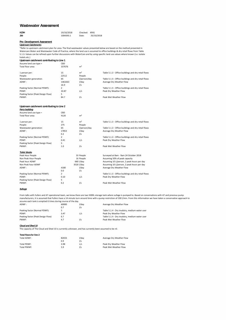
Upstream catchment contributing to Line 1Assume land use type = CBDTotal floor area: 337676 m²
1 person per: 15 m² Table 5.1.3 - Office buildings and dry retail flowsPeople: 22512 PeopleWastewater generation: 65 l/person/day Table 5.1.3 - Office buildings and dry retail flowsADWF : 1463263 l/day Average Dry Weather Flow
16.9 l/sPeaking factor (Normal PDWF): 2 Table 5.1.3 - Office buildings and dry retail flowsPDWF: 33.87 L/s Peak Dry Weather FlowPeaking factor (Peak Design Flow) 5PWWF: 84.7 l/s Peak Wet Weather Flow
Upstream catchment contributing to Line 2Ferry buildingAssume land use type = CBDTotal floor area: 4120 m²
1 person per: 15 m² Table 5.1.3 - Office buildings and dry retail flowsPeople: 275 PeopleWastewater generation: 65 l/person/day Table 5.1.3 - Office buildings and dry retail flowsADWF : 17853 l/day Average Dry Weather Flow
0.2 l/sPeaking factor (Normal PDWF): 2 Table 5.1.3 - Office buildings and dry retail flowsPDWF: 0.41 L/s Peak Dry Weather FlowPeaking factor (Peak Design Flow) 5PWWF: 1.0 l/s Peak Wet Weather Flow
Toilet blocksPeak Hour People 33 People Surveyed at 8am - 9am 24 October 2018Non Peak Hour People 16 People Assuming 50% of peak capacityPeak hour ADWF 660 l/day Assuming 10 L/person, 2 peak hours per dayNon Peak hour ADWF 3520 l/day Assuming 10 L/person, 2 peak hours per dayADWF : 4180 l/day Average Dry Weather Flow
0.0 l/sPeaking factor (Normal PDWF): 2 Table 5.1.3 - Office buildings and dry retail flowsPDWF: 0.10 L/s Peak Dry Weather FlowPeaking factor (Peak Design Flow) 5PWWF: 0.2 l/s Peak Wet Weather Flow
Sullage
ADWF : 60000 l/day Average Dry Weather Flow0.7 l/s
Peaking factor (Normal PDWF): 5 Table 5.1.4 - Dry inudstry, medium water userPDWF: 3.47 L/s Peak Dry Weather FlowPeaking factor (Peak Design Flow) 6.7 Table 5.1.4 - Dry inudstry, medium water userPWWF: 4.7 l/s Peak Wet Weather Flow
Cloud and Shed 10The capacity of The Cloud and Shed 10 is currently unknown, and has currently been assumed to be nil.
Total flows for line 2Total ADWF : 82033 l/day Average Dry Weather Flow
0.9 l/sTotal PDWF: 3.98 L/s Peak Dry Weather FlowTotal PWWF: 5.9 l/s Peak Wet Weather Flow
*Refer to upstream catchment plan for area. The final wastewater values presented below are based on the method presented inWatercare Water and Wastewater Code of Practice, where the land use is assumed to office buildings & dry retail flows from Table5.1.3. Values can be refined upon further discussions with WaterCare and by using specific land use values where known (i.e. isolatehotels etc.)
From talks with Fullers and AT operational team, we know there are two 5000L storage tank where sullage is pumped to. Based on conversations with AT and previous pumpmanufacturers, it is assumed that Fullers have a 14 minute turn around time with a pump restriction of 200 l/min. From this information we have taken a conservative approach toassume each tank is emptied 6 times during course of the day.

Post- Development AssessmentUpstream catchment contributing to Line 1We believe that no change will occur to the upstream wastewater generation for line 1PWWF: 84.7 l/s % of Line 3 Capacity 88.2
Upstream catchment contributing to Line 2Ferry buildingWe believe that no change will occur to the ferry building wastewater generationPWWF: 1.0 l/s
Sullage
PWWF: 4.7 l/s
Toilet Blocks
Peak Hour People 66 People Surveyed at 8am - 9am 24 and 25 October 2018Non Peak Hour People 32 People Assuming 50% of peak capacityPeak hour ADWF 1320 l/day Assuming 10 L/person, 2 peak hours per dayNon Peak hour ADWF 7040 l/day Assuming 10 L/person, 2 peak hours per dayADWF : 8360 l/day Average Dry Weather Flow
0.1 l/sPeaking factor: 2 5.3.5.1.aii)PDWF: 0.19 L/s Peak Dry Weather FlowInfiltration: 5PWWF: 0.5 l/s Peak Wet Weather Flow
Capacity of downstream pipes
For Concrete pipes Mannings Coefficient = 0.013. Invert levels and pipe sizes obtained from Auckland Council GIS
ID Diameter (mm) IL In IL Out Length Slope(m/m)Capacity (l/s)Line 3 375 0.08 -0.07 46 -0.003 96Line 4 400 -0.07 -0.25 91 -0.002 93
Line 3 - PWWF 90.8 l/sLine 3 94.6 %
Line 4 - PWWF 90.8 l/s Not including additional contribution from downstream CBD buildingsLine 4 - PWWF 97.7 %From our analysis it is anticipated the pipes within the immediate vicinity of the development will have sufficient capacity to accommodate the wastewater flows from the proposeddevelopment.
Post development capacity used
A new sullage tank will be installed next to the current one at Pier 1. However, we believe that the current sullage demands will not increase with the installation of 6 new ferry berths.
Information from Isthmus ( email dated 16 October 2018), shows the proposed plans as doubling the current amount of toilet and basin systems. As the toilet facilities are proposed to bemade public, it is assumed that double the amount of people will use both in peak and non peak hours.

I2
!!!!!!!!
!!!!
!!!!
!!!!
!!!!!!!! !!!!
!!!!!!!!
!!!!
!!!!
!!!!
!!!!
!!!!
!!!!
!!!!
!!!!
!!!!
!!!!
!!!!
!!!!
!!!!!!!!
!!!!
!!!!
!!!!
!!!!!!!!
!!!!
!!!! !!!!
!!!!
!!!!!!!!
!!!!
!!!!
!!!!!!!! !!!!!!!!
!!!!
!!!!
!!!!
!!!!
!!!!
!!!!
!!!!
!!!!
!!!!
!!!!
!!!!
!!!!
!!!!
!!!!
!!!!
!!!!
!!!!
!!!!
!!!!
!!!!
!!!!
!!!!
!!!!!!!!
!!!!
!!!!
!!!!
!!!!!!!!
!!!!
!!!!!!!!
!!!!
!!!!
!!!!
!!!!
!!!! !!!!
!!!!
!!!!
!!!!!!!!
!!!!
!!!!
!!!!
!!!! !!!!
!!!!
!!!!
!!!! !!!!
!!!!
!!!!
!!!!
!!!!
!!!!!!!!
!!!!
!!!!
!!!!
!!!!
!!!!
!!!!!!!!
!!!!
!!!!
!!!!!!!!!!!!
!!!!
!!!!
!!!!!!!!
!!!!
!!!!!!!!
!!!!
!!!!
!!!!
!!!!
!!!!
!!!!
!!!!
!!!!
!!!!
!!!!!!!!
!!!!
!!!!
!!!!
!!!!
!!!! !!!!
!!!!
!!!!!!!!
!!!!
!!!!!!!!
!!!!
!!!!
!!!!!!!!
!!!!!!!!
!!!!
!!!!
!!!!
!!!!
!!!!
!!!!
!!!!
!!!!
!!!!
!!!!
!!!!
!!!!
75
44-50
2
43
23
25-39
3A
13-21
915
53
69
156
30
4A
117
2234-36
120
48
114104
220
86-102
57
210
117A115
161-173
117
75
2210
10
67
8
34
4
36
148
79
26
20
18
57
12A
17
30
8
2
45
3
22
196
10
152
29
26
12 122
2
18
10
21
2
130
46
12
17
17
21
44
1
188
20
23
2
102
1124
14
85
104
48110
20
125
20
120
99
29
128
149
95
132
131
4
24
119
106 85
103
11
121
16
109
32
13615
28
73
1
204
7
BritomartRailwayStation
Scale @ A31:2,500
Date Printed:19/10/2018
0 25 50 75
Meters
=
´
DISCLAIMER:This map/plan is il lustrative only and all information should beindependently verified on site before taking any action. CopyrightAuckland Council. Land Parcel Boundary information from LINZ(Crown Copyright Reserved). Whilst due care has been taken,Auckland Council gives no warranty as to the accuracy and plancompleteness of any information on this map/plan and accepts noliability for any error, omission or use of the information.Height datum: Auckland 1946.
MapAuckland Council
Area = 693 m2
(19 levels)
Ground Floor Area
= 4442 m2
High rise Area =
1580 m2(29 levels)
High rise Area =
1140 m2(21 levels)
Ground Floor Area
= 2310 m2
High rise Area =
1770 m2(13 levels)
Ground Floor Area
= 1485m2
High rise Area =
1780 m2(6 levels)
Ground Floor Area
= 2300 m2
Carpark
Area = 1500 m2
(3 levels)
Area = 1685 m2
(6 levels)
Area = 1836 m2
(2 levels)
Area = 750 m2
(2 levels)
High rise Area =
3060 m2(34 levels)
Line 2Line 1
Ground Floor Area
= 3595 m2
Commercial bay Plan from
https://www.precinct.co.nz/
assets/Commercial-Bay-
Presentation.pdf
Area = 1030 m2
(4 levels)
Line 3
Line 4
Area = 90 m2(1 levels)
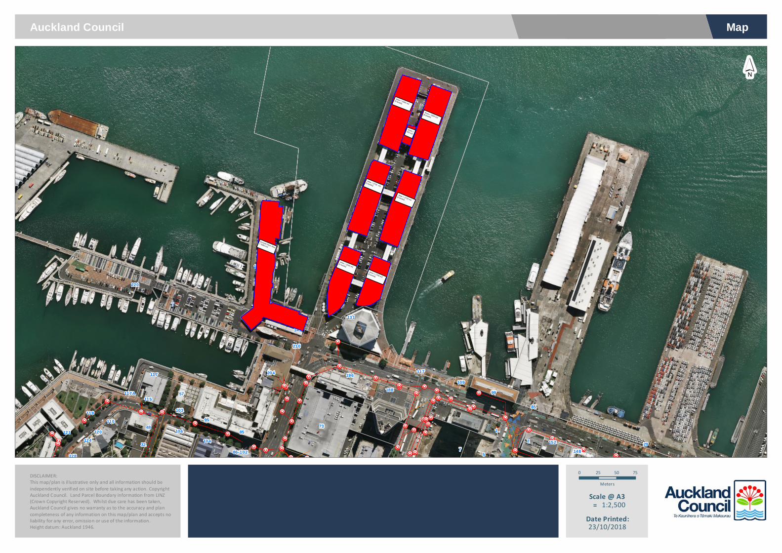
!!!!
!!!!
!!!!!!!!
!!!!
!!!!
!!!! !!!!
!!!!
!!!!!!!!
!!!!
!!!!
!!!!
!!!!!!!!
!!!!!!!!
!!!!
!!!!
!!!!
!!!!
!!!!
!!!! !!!!
!!!!
!!!! !!!!
!!!!
!!!!
!!!!
!!!!
!!!!
!!!!
!!!!
!!!!
!!!! !!!!
!!!!
!!!!!!!!
!!!!
!!!!
!!!! !!!!
!!!!
!!!!!!!!
!!!!!!!!
!!!!!!!!
!!!!
!!!!7
5
117
220
86-102
57
210
117A115
161-173
117
148
196
1522
188
1124
85
104
48110
120
99
29
128
149
95
131
119
106 85
103
121
109
32
73
204
Scale @ A31:2,500
Date Printed:23/10/2018
0 25 50 75
Meters
=
´
DISCLAIMER:This map/plan is il lustrative only and all information should beindependently verified on site before taking any action. CopyrightAuckland Council. Land Parcel Boundary information from LINZ(Crown Copyright Reserved). Whilst due care has been taken,Auckland Council gives no warranty as to the accuracy and plancompleteness of any information on this map/plan and accepts noliability for any error, omission or use of the information.Height datum: Auckland 1946.
MapAuckland Council
Area = 2640 m2
(5 levels)
Ground Floor Area
= 5450 m2
Area = 2240 m2
(5 levels)
Area = 1705 m2
(5 levels)
Area = 2725 m2
(5 levels)
Area = 2725 m2
(5 levels)
Area =320 m2
Area = 2300 m2
(9 levels)
Area = 2300 m2
(9 levels)

I2
!!!!
!!!!
!!!!
!!!!
!!!!
!!!!
!!!!
!!!!
!!!!
!!!!
!!!!
!!!
!
!
!
!
!
TYLER STREET
TYLER STREET
COMM
ERCE
STR
EET
QUEE
N ST
REET
QUAY STREET
QUAY STREET
150EW
150EW
150 EW
225CONC
150 AC
225 AC
150 C
LCI
225 EW
150 E
W
150 E
W
300 E
W
400 CONC
300 EW
375 CONC
150
150
400 C
ONC
300
150
3.5
2
3.5
2.5
0.5
3.5
21
2.5
3
3.5
3.5
3.5
3
1.5
3.5
3.5
3.5
3.5
3//21
6E/148
152R
2H
5
148
152
12
2
1
85
BritomartRailwayStation
Scale @ A31:500
Date Printed:19/10/2018
0 5 10 15
Meters
=
´
DISCLAIMER:This map/plan is il lustrative only and all information should beindependently verified on site before taking any action. CopyrightAuckland Council. Land Parcel Boundary information from LINZ(Crown Copyright Reserved). Whilst due care has been taken,Auckland Council gives no warranty as to the accuracy and plancompleteness of any information on this map/plan and accepts noliability for any error, omission or use of the information.Height datum: Auckland 1946.
Invert Levels
MapAuckland Council
0.08 m
-0.07 m
-0.25 m

Appendix D : Water Supply

!
!
!
!
!
!
!
!
!
!
!
!
!
!
!
!
!
!
!
!
!
!
!
(
(
(
(
(
(
(
(
3
3
3
3
3
3
3
3
3
3
3
100
100
200 AC
250 AC
250 C
I
375 560
150 C
I
250 DI
20 PE
20 PE
20 PE
200 CI
100 C
LS
20 PE
20 PE
20 PE
250 CI
20 PE
20 PE
150 AC
200 CLCI
150 CI
200 AC
QUEE
N ST
REET
QUAY STREET
QUAY STREET
160
111
99
1
85
99
109
´
Scale @ A41:500
Date Printed:19/10/2018
0 3.5 7 10.5
Meters
=Water Supply
DISCLAIMER:This map/plan is illustrative only and all information should beindependently verified on site before taking any action.Copyright Auckland Council. Land Parcel Boundary informationfrom LINZ (Crown Copyright Reserved). Whilst due care hasbeen taken, Auckland Council gives no warranty as to theaccuracy and plan completeness of any information on thismap/plan and accepts no liability for any error, omission or useof the information. Height datum: Auckland 1946.
Auckland Council Map

Scale @ A31:1,000
Date Printed:30/10/2018
0 10 20 30
Meters
=
´
DISCLAIMER:This map/plan is il lustrative only and all information should beindependently verified on site before taking any action. CopyrightAuckland Council. Land Parcel Boundary information from LINZ(Crown Copyright Reserved). Whilst due care has been taken,Auckland Council gives no warranty as to the accuracy and plancompleteness of any information on this map/plan and accepts noliability for any error, omission or use of the information.Height datum: Auckland 1946.
MapAuckland Council
10m
70m
50m
Approximate Existing Fire Hydrant locations

Date Printed:30/10/2018
Legend
DISCLAIMER:This map/plan is illustrative only and all information should beindependently verified on site before taking any action.Copyright Auckland Council. Land Parcel Boundary informationfrom LINZ (Crown Copyright Reserved). Whilst due care hasbeen taken, Auckland Council gives no warranty as to theaccuracy and plan completeness of any information on thismap/plan and accepts no liability for any error, omission or useof the information. Height datum: Auckland 1946.
Auckland Council MapRail Stations (8,000)I2 Rail Stations (8,000)
Railway (2,500)Railway (2,500)
Auckland Council BoundaryAuckland Council Boundary
Roads (1,000)Parcels
Parcels
LakesLakes
Base Region (CRS)Land Outside
Water
Region Cache Public Open Space ExtentRegion Cache Public Open Space Extent
