dr2 written report.docx
TRANSCRIPT

Optimizing MakaPad Drying Process
Team 08: Mario Arjona, Matt Meisel, Peter Warendorf, Noam Zimet
Project Sponsors: Elijah Kannatey-Asibu Jr., Moses Kizza Musaazi, Chinedum Okwudire

EXECUTIVE SUMMARY A major roadblock to educational success for African girls is continual absence in school due to the natural cycle of menstruation. Unable to afford sanitary pads to absorb blood from menstruation, many girls choose to skip school rather than face the embarrassment of blood leaking during class. These accumulated absences cause the girls to continually fall behind in their classes, ultimately causing many to drop out of school. As a result, as many as 80% of girls in Uganda who begin primary school will never complete their education. In order to combat this issue, Professor Moses Musaazi in Uganda has created the MakaPad, a feminine hygiene pad that is manufactured from cheap, locally-available products. The MakaPads are made using the fibers of papyrus and paper waste, which are then beaten, dried and softened without using electricity. To dry, the paper is placed onto mesh-covered frames. Initially, the paper is too wet to be positioned vertically due to gravitational forces that would cause the mixture to simply collect on the bottom instead of retaining its shape. Therefore, it is placed either horizontally or at an angle, thus occupying significantly more space than if it could simply be placed vertically at the beginning. The drying process is one of the main bottlenecks of the production process, both because of the space that it occupies as well as time necessary for the pads to dry. In order to facilitate Professor Musaazi’s dream of tripling current MakaPad production, our team has created a foot operated drying press that will decrease the drying time by 39%. Previous attempts to achieve this task include a rotating device that utilizes centrifugal force to remove water as well as a press that removed excess water through compression. Although the rotating device improved the drying time, it was not compatible with the Ugandan workers who preferred designs with which they were more familiar. This is a challenge that our team can overcome through adequate correspondence with Professor Musaazi. He believes that a compression press is an adequate solution as it improves the drying time while using technology with which Ugandan workers are familiar. With the limited materials available in Uganda, our device is made almost exclusively out of PVC with only three parts made of simply manufactured aluminum. The idea behind our press is that the worker can scoop out two sheets of pulp and then place them directly into our machine, the worker will then press the foot pedal and press dry the sheets, the excess water will be collected and then the sheets can be placed on drying racks for air drying. We have demonstrated in our tests that our press decreases the dry time by 39% so our next step is to go to Uganda to build a press there. Two of our team members will be traveling there in the coming weeks to set up the machine and get worker feedback. Our hope is that the workers will accept this machine and that it can be used at all of their production facilities so that Professor Musaazi can reach his goal of tripling production.
Table of Contents 1. SPONSORS ............................................................................................................................................. 1
2. BACKGROUND ..................................................................................................................................... 1
3. PROBLEM STATEMENT .................................................................................................................... 2
4. USER REQUIREMENTS AND ENGINEERING SPECIFICATIONS ............................................ 2
4.1 Benchmarks ............................................................................................................................... 3
4.2 Competitor Products .................................................................................................................. 4
5. CONCEPT GENERATION ................................................................................................................... 5
5.1 Discussion of Concepts .............................................................................................................. 6
6. CONCEPT SELECTION ....................................................................................................................... 7
7. DESIGN DRIVERS ................................................................................................................................ 9
7.1 Challenges ................................................................................................................................ 10
8. CONCEPT DESCRIPTION ................................................................................................................ 11
9. ENGINEERING ANALYSIS............................................................................................................... 14
9.1 Testing ..................................................................................................................................... 14
10. RISK ANALYSIS ................................................................................................................................ 18
11. VALIDATION ..................................................................................................................................... 20
12. DISCUSSION ...................................................................................................................................... 21
12.1 Design Critique ...................................................................................................................... 21
12.2 Future Work ........................................................................................................................... 21
REFERENCES .......................................................................................................................................... 23
AUTHORS ................................................................................................................................................. 24
APPENDIX A: Concept Sketches ............................................................................................................ 26
APPENDIX B: Previous Semester’s Design ........................................................................................... 38
APPENDIX C: Personal Statements ....................................................................................................... 39
C.1 Environmental Impact ............................................................................................................. 39
C.2 Ethics of Design ...................................................................................................................... 41
APPENDIX D: Materials and Manufacturing Plans ............................................................................. 45
D.1 Manufacturing Plan ................................................................................................................. 45
D.2 Bill of Materials ...................................................................................................................... 47
APPENDIX E: Engineering Drawings .................................................................................................... 48
1. SPONSORS Professor Moses Kizza Musaazi Professor Musaazi is a Ugandan entrepreneur with a degree in electrical engineering from the University of London. He is a professor of electrical engineering at Makerere University in Kampala, Uganda. He is also the founder of Technology for Tomorrow, a company that focuses on creating appropriate technologies in areas of economic hardship. Musaazi has created the MakaPad during his time with Technology for Tomorrow, and he is our group’s point of contact in Uganda. Professor Elijah Kannatey-Asibu Jr. Professor Kannatey-Asibu is a professor of mechanical engineering at the University of Michigan and specializes in manufacturing processes. He has received numerous awards for contributions to engineering, most recently having been nominated for the SME Education Award in 2015. He is one of the professors of ME 450 this semester. Professor Chinedum Okwudire Professor Okwudire is a professor of mechanical engineering at the University of Michigan and researches many topics including sustainable manufacturing and mechatronics. He has traveled to Uganda in the past to visit the MakaPad facilities and, as such, is a valuable source of information for our group. 2. BACKGROUND In Uganda, women are equal by law, but they are often treated as inferior [1]. One of the best ways to combat this inequality is through education; however, a major roadblock to educational success for African girls is continual absence in school due to their natural cycles of menstruation. Unable to afford sanitary pads to absorb blood during menstruation, many girls choose to skip school rather than face the embarrassment of blood leaking during class [2]. This leads to girls skipping as many as 4 to 5 day per month of classes, according to a UNICEF study [3]. In a recent study, up to 95% of girls in rural regions of Ghana reported to have missed school due to menstruation because they lack proper sanitary pads [4]. These accumulated absences cause the girls to continually be behind in their classes, ultimately causing many to drop out of school. As a result, as many as 80% of girls in Uganda who begin primary school will never complete their education [5]. A study involving Kenyan girls produced similar results, proving that this problem is persistent across several countries in Africa [6]. In order to combat this issue, Moses Musaazi in Uganda founded Technology for Tomorrow, a company that has developed a process to create feminine hygiene pads from cheap, locally- available materials [7]. The process involves extracting fiber from the locally abundant papyrus
1

plant, which he then mixes with paper and water. Next, the mixture is placed on a mesh screen, drip-dried, and then placed in the sun to continue drying. When the sheets are dry, they are run through a mechanical softener and then they are inserted into the MakaPad and packaged to be sold [8]. The United Nations Higher Compensation for Refugees organization (UNHCR) is the largest consumer of MakaPads, purchasing approximately 90% of the pads produced by Technology for Tomorrow and distributing them for free to refugees across Africa. MakaPads have a distinct impact on the lives of the 190,000 refugees in Uganda, both as a reliable woman's sanity pad and as a source of jobs. Refugees are employed to help in the MakaPad production process with the hope of teaching them necessary skills and giving them an opportunity to earn an income to support themselves and their family. There is even a MakaPad production facility located in a refugee settlement in Southern Uganda, which employs over 50 refugees and is overseen by a refugee [9]. Additionally, MakaPad employs both men and women in a country where there is still a fight for gender equality [10]. Purchasing orders from the UNHCR arrive sporadically. Since storage space is limited at the Technology for Tomorrow production facility, MakaPads are unable to be produced and stored in advance in anticipation of orders. Therefore, many MakaPads have to be prepared at once in order to meet demand from UNHCR. We have been tasked with decreasing the drying time so that the rate of MakaPad production can be increased to meet the high demand [11]. 3. PROBLEM STATEMENT Professor Musaazi would like to triple current production from 5 million to 15 million pads a year. Currently, a bottleneck occurs during the drying stage of production, which takes anywhere from 6 to 8 hours, limiting production. Our team has been tasked with finding an appropriate solution to minimize this drying time while keeping costs low and staying within the bounds of Ugandan cultural expectations. Our goal, as given to us by our sponsor, is to create a device that improves the drying time by at least 30%, collects 50% of the excess water for reuse, and increase sheet production by a factor of three [12]. 4. USER REQUIREMENTS AND ENGINEERING SPECIFICATIONS Our user requirements and engineering specifications shown in Table 1 (pg. 3) were derived from a combination of the results of our sponsor interviews and the work done by past ME 450 MakaPad drying teams, which has been confirmed by Dr. Musaazi. Our team then ranked the products based on their importance to the final product. Our priorities are shown below in Table 1, where the rank of 1 is the most important and 6 is the least important.
2
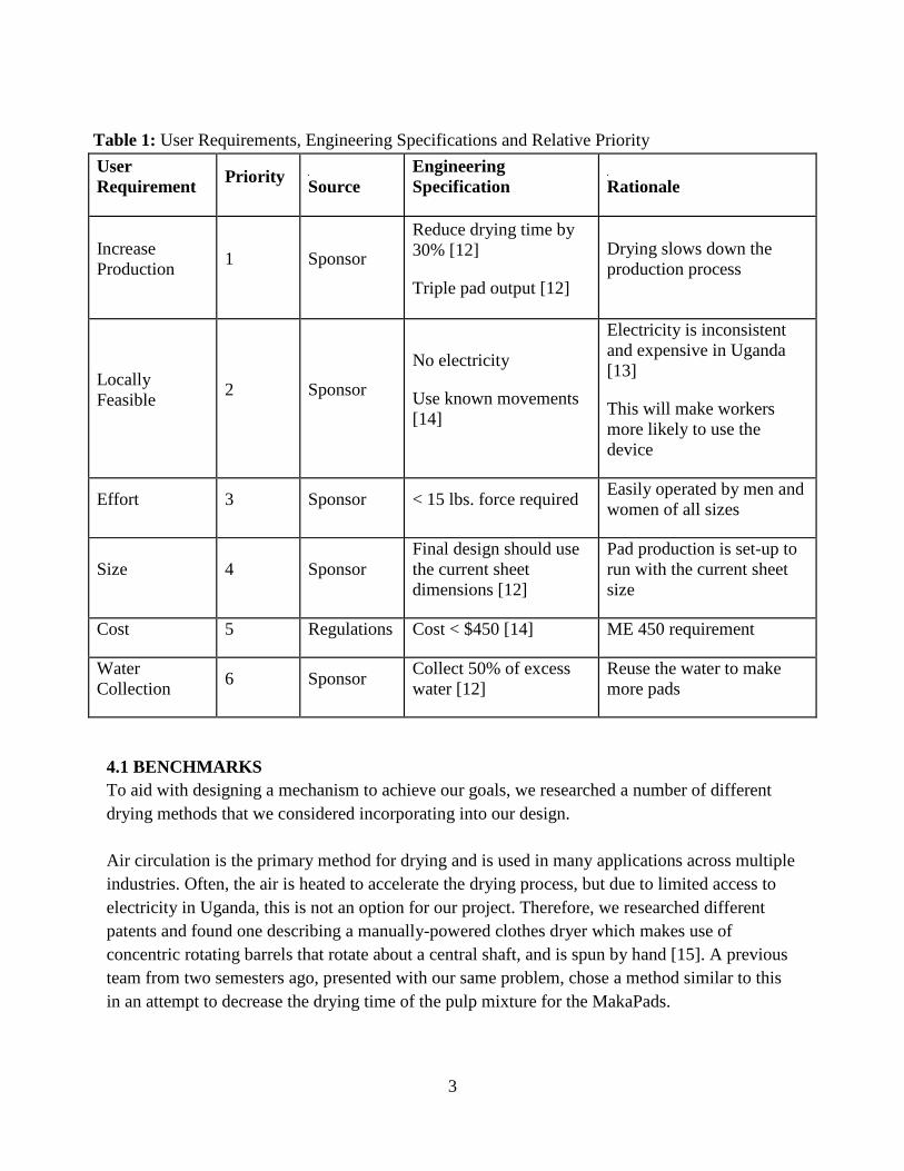
Table 1: User Requirements, Engineering Specifications and Relative Priority User Requirement Priority
Source Engineering Specification
Rationale
Increase Production 1 Sponsor
Reduce drying time by 30% [12]
Triple pad output [12]
Drying slows down the production process
Locally Feasible 2 Sponsor
No electricity
Use known movements [14]
Electricity is inconsistent and expensive in Uganda [13]
This will make workers more likely to use the device
Effort 3 Sponsor < 15 lbs. force required Easily operated by men and women of all sizes
Size 4 Sponsor Final design should use the current sheet dimensions [12]
Pad production is set-up to run with the current sheet size
Cost 5 Regulations Cost < $450 [14] ME 450 requirement
Water Collection 6 Sponsor Collect 50% of excess
water [12] Reuse the water to make more pads
4.1 BENCHMARKS To aid with designing a mechanism to achieve our goals, we researched a number of different drying methods that we considered incorporating into our design. Air circulation is the primary method for drying and is used in many applications across multiple industries. Often, the air is heated to accelerate the drying process, but due to limited access to electricity in Uganda, this is not an option for our project. Therefore, we researched different patents and found one describing a manually-powered clothes dryer which makes use of concentric rotating barrels that rotate about a central shaft, and is spun by hand [15]. A previous team from two semesters ago, presented with our same problem, chose a method similar to this in an attempt to decrease the drying time of the pulp mixture for the MakaPads.
3
Drying presses can also be utilized to reduce the drying time of the pulp mixture. One type of drying press that we discovered during our research focuses on using a heated platen that presses down onto the object to dry it [16]. As we have no efficient means of heating the platen, this method is out of reach for our needs. However, we could use a type of press that relies on compression force to squeeze out the liquid from the object that needs to be dried. In a variation of this design, the object is placed between two flat surfaces, and is then pressed between the surfaces using a lever, or similar mechanism, thereby forcing the liquid out of the object [17]. This approach is much more accommodating to our available resources. This type of press was pursued by the last semester’s group to attempt to tackle the problem at hand. Another idea we considered was based upon a patent we found during our research. The machine is designed to accept a continuous feed of pulp mixture from a roll, where it passes over heated rollers in an effort to raise the temperature rapidly. The goal is to raise the temperature high enough so that the moisture begins to vaporize from the pulp. The pulp is then passed over a device that draws a vacuum through the mixture, thereby further reducing the moisture content [18]. We found this idea very intriguing in the sense that a worker could continuously pass individual pads through the machine, versus being on a roll, which simplify the worker’s role in the production of the MakaPads. We decided that this could not be a feasible option, however, because the mechanism would rely too heavily on electricity, which is scarce within Uganda. Building upon the previously described mechanism, we discovered an additional patent to a machine that dries a wet paper web. The web is placed on a porous belt, where it is brought into contact with a top and bottom fabric layer which absorb moisture, while simultaneously passing air through the belt-and-web layer to promote even faster drying [19]. This design is also out of reach for us, but it provoked thought of combining multiple different drying processes together in one machine, widening our window of possibilities. The current solution for drying the pads is to place the screens containing the wet pulp mixture onto suspended racks, where they are angled toward the sun, and left to air dry. This current method is insufficient because it takes a long period of time to completely dry the pads, between 6 and 8 hours depending on the amount of available sunlight, as well as the amount of land needed to support the many racks of screens. We have developed a device that we have shown will decrease the drying time by 39%. 4.2 COMPETITOR PRODUCTS There currently exist other companies that manufacture feminine products for purchase in Africa, including Uganda-based AFRIPad and Kenya-based SafiPad. However, both of these companies manufacture reusable pads, which though in principle seems like a superior solution, is not ideal for impoverished people with limited access to cleaning supplies. One MakaPad user recounts that “Previously, many [Ugandans] used cloth or toilet paper; the problem with the cloth was that one may not have soap with which to wash it, sometimes water is hard to come by, so you could
4

end up with a bad smell as a result” [20]. She continues to say that “since the MakaPads were introduced, the days of periods being depressing are gone” [20]. 5. CONCEPT GENERATION In order to generate concepts for an appropriate drying mechanism, our team first researched which characteristics were necessary for our design. As determined during the last design review through speaking with our project sponsors, our team was able to determine the following characteristics as vital to our design: fast throughput time, manufacturable with locally-available materials, feasibility within the Ugandan culture, cost, ease of operation, maintenance of sheet integrity, collection of water, manufacturability, and size. Concepts for this project were designed through individual brainstorming as well as through the process of functional decomposition. When brainstorming, each team member was tasked with ideating 5 full-solution concepts, resulting in a total of 20 concepts. During this process, our team considered all concepts, allowing for a wide range of concepts ranging from an electrically powered conveyor belt to a spinning rack for sun drying. Once everyone had generated their respective concepts, we analyzed each as a group and selected the 5 concepts that we felt would be most likely to achieve our design specifications. The process of functional decomposition as applicable to our project is shown in detail in Figure 1 below. All concepts were initially considered and were then narrowed by available materials, technology, and electricity. Any concept that was not feasible enough to be utilized in Uganda was not considered in this section. However, all original ideas can be found in Appendix A. The most promising concepts are discussed in detail in section 5.1.
Figure 1: Functional decomposition for a pulp sheet drying mechanism [21]
5

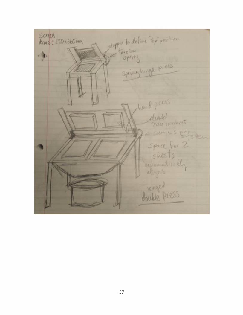
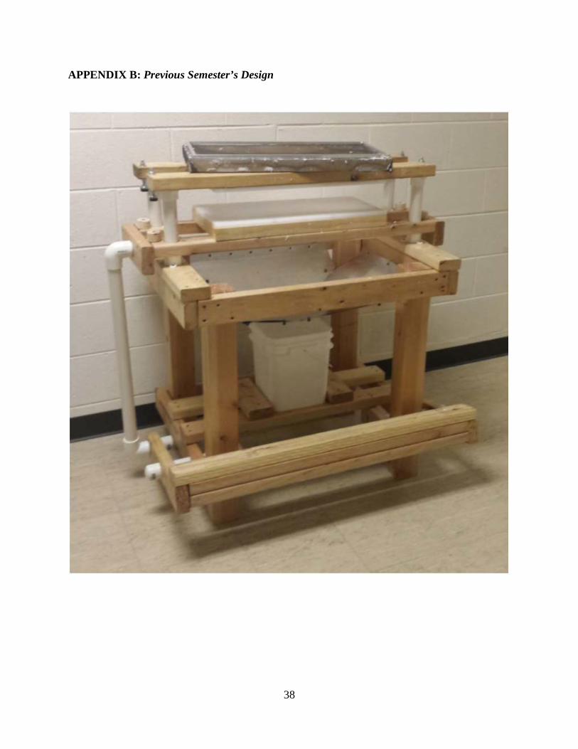
5.1 DISCUSSION OF CONCEPTS Previous Design: This concept was designed by the ME450 group that worked on this same problem in the previous semester. It is made primarily out of wood and PVC pipe, materials which are readily available in Uganda. The device was designed to press the excess water out of the pulp mixture using a foot press. The user pushed down the weighted pedal with one foot and the sheet is then raised up into a felt covered, plastic piece which removes excess water through compression. The weight of the pedal then causes a return to the initial position so that the operator can press-dry another sheet. The press is very easy to use and we believe that the workers will enjoy using. One of the main concerns expressed by Professor Musaazi is that the compression could compromise the integrity of the pad. Additionally, the design occupies more space that seems necessary to accomplish the desired task. An image of this design can be found in Appendix B. Double Press: The double press concept is a direct follow-up from the previous design. Professor Musaazi has confirmed that he likes the press idea and hence, this press concept could be a good option to improve upon the previous design. One of the issues that our group sees with the previous design is that it takes up a lot of space but it is only able to dry one sheet at a time. The double press would use the same drying method as the previous design but would include room for two sheets. This would allow the user to press-dry twice the number of sheets in the same amount of time. The main challenge in feasibility with this design is to make sure that the device does not over compress the pulp, which could compromise the integrity of the paper and reduce the absorptivity of the sheets. Roller: This concept would also use force to push out the water but it would only require the worker to roll an object over the sheets. In a way similar to rolling out dough, the user would roll a cylindrical object over the pulp after it has been put into sheets. We believe that this would be an easy process for the local workers to adapt to because of the familiarity of the motions. Workers would be able to dry a large number of sheets in a short time because the sheets can easily be moved and rolled very quickly. Overall, this concept is feasible, but suffers from the large amount of force required to operate the device; the roller would require the user to apply a relatively large downward force in order to remove enough of the water to make this design feasible. Spinning Sun Rack: This concept would be an improvement of the sun-drying process that is already in place in Uganda. One of the problems with the sun drying that is currently taking place is that the sheets are not always in direct sunlight. Our drying rack would have an axis of rotation that would allow a worker to rotate the rack so that the sheets are all in direct sunlight for the maximum amount of time every day. This design is not particularly feasible because the amount of space that these rotating racks would require. Another problem is that we wouldn't be
6

able to collect any of the excess water because the sheets would be drying almost exclusively through evaporation. Conveyor Belt: This concept would use a conveyor belt to move the sheets while hot air is blown up through holes in the belt in order to dry the sheets. An electrically powered conveyor would be ideal to use in this scenario because it would allow us to increase the production and it would also decrease the amount of time that it would take to dry each sheet. However, this design is not feasible because it would require electricity, which is inconsistent in Uganda. Our team would like to avoid choosing a concept that complicates and adds expense to the process. Merry-Go-Round: This concept works in the same manner as the common piece of playground equipment that rotates as a child pushes the outer rim of the equipment. Pads would be placed in a conical support structure similar to the one currently used to dry the pads. Then, a person would spin the structure, the resulting wind causing the pads to dry faster than they would if they were just left in the air. A benefit of this system is that it makes use of an already existent structure in Uganda, thus simplifying construction. Another benefit is that it could be a fun activity for children who are nearby. However, this device may be unfeasible due to the likelihood of the user getting dizzy from continued rotation. Our team has decided to eliminate the centrifugal drying mechanism from two semesters ago from consideration in our future plans. Professor Musaazi has voiced his displeasure with the way the Ugandan workers adapted to it, and with its subsequent decline in usage. We have decided that is in our best interest to not pursue a concept that has already had no measurable success in the working environment. 6. CONCEPT SELECTION Feasibility and appropriateness of generated concepts were measured through a Pugh Chart comparison, as shown in Table 2 (pg. 8). Each user specification was prescribed a weight based on its importance to our project. A weight of 5 represented the specification which was most essential to a successful project, while a weight of 1 represented a specification which would be a nice addition, but was not mandatory for success of the project. New concepts were compared against the baseline of the previous semester’s dry-press design, in which Professor Musaazi has already expressed interest. When comparing different concepts, a positive number represented an improvement over the baseline, while a negative number represented a worse solution than the baseline. Each concept’s score was generated by multiplying the user specification weight by the grade received by the concept. The user specifications used in the Pugh Chart and justifications for their respective weights are discussed in greater detail in the paragraphs following this chart.
7

Table 2: Pugh Chart comparison of ideated concepts Weight Previous
Design Double Press
Roller Spinning Sun Rack
Conveyer Belt
Merry- Go-
Round Throughput Time 5 0 2 0 -2 3 -1 Made from Locally- Available Materials
5 0 0 0 0 -3 0
Feasibility within Ugandan Culture
4 0 0 0 -1 -2 -2
Cost 4 0 -1 0 2 -3 -2 Ease of Operation 3 0 0 0 -1 2 -2 Maintains Sheet Integrity
3 0 0 -1 1 3 1
Water Collection 2 0 0 0 0 -3 -1 Manufacturability 1 0 -1 0 0 -2 -1 Size 1 0 -1 1 -2 -2 -1 Total 0 4 -2 -8 -15 -28
Decreasing throughput time correlates directly with increasing production, the characteristic designated by Professor Musaazi as the most important for our team’s mechanism to achieve. Ideally, our design would allow for a threefold increase in MakaPad production. The fact that Musaazi specified increasing production as our most important design criteria caused us to rank increasing throughput with the highest priority, a weight of 5 out of 5. The materials that we use need to be available to the people in Uganda. In the U.S., we have access to many materials and manufacturing processes but we need to ensure this project is feasible in Uganda. If it improves the process, Technology for Tomorrow would like to use our drying machine at all of their sites so they would need to be able to replicate what we have done with only the materials that they have available to them. Therefore, this criteria was also ranked with the highest weight of 5. Feasibility within the Ugandan culture is important because our team wants our project to be accepted and used in Uganda. During the first iteration of this project, the ME450 team did not make the design culturally appropriate and it was therefore not used. Not wanting to have the same pitfall, our team places importance on keeping with the Ugandan culture and have awarded this specification a weight of 4. Cost is an important consideration for two reasons. First, it needs to be cheap enough to build within our $450 project budget for the ME450 class. Secondly, it needs to be cheap enough to make replication in Uganda economically feasible. Because of the necessity to stay within both of these guidelines, cost was assigned a weight of 4.
8

Ease of operation is important because we want the MakaPad employees to understand and even enjoy using the device. However, even if the device is difficult to operate, there should be other employees to train the new worker to use the device; hence, this specification was assigned a weight of 3. Maintaining sheet integrity is important because Professor Musaazi has identified that a potential source of error would be to compress the sheet so much that it would lose its absorptivity. Understanding that the pad is not useful if it has lost this property, our team has given this specification a weight of 3. Water collection is important because Professor Musaazi has indicated that collecting the water that is removed during drying is a desirable function for our machine to possess. All of the water that we are able to collect can be reused in the MakaPad creation process which will save money and time. Ultimately, this specification would be a nice feature but Professor Musaazi has indicated that it is not mandatory so our team has given this specification a weight of 2. Manufacturability is also important for our design. Since Professor Musaazi has expressed interest in replicating this device many times, it should be easy to make the parts and to assemble. This is an important category but due to the simple, common-nature of our materials, we do not see this having a big impact on our design and for this reason we gave it a weight of 1. The size of our device is a measure of how much space our design is going to take up. We are aiming to keep our device as small as possible but we believe that even if it is large, as long as it decreases the drying time, it will save space overall. For this reason we are giving the size of the machine criteria the lowest weight of 1. Our preliminary concepts each had components that our group deemed desirable to achieve our main goal of increasing production capability of the MakaPad facilities. However, after using the Pugh Chart to compare the choices, we found that with a total score of +4, the double press was the best choice. 7. DESIGN DRIVERS Water Extraction Method: The overarching engineering challenge in our project is to decrease total drying time by extracting water from the mixture used to create MakaPads before they are set to dry. This decrease in drying time will help achieve Professor Musaazi’s goal of increasing MakaPad production. While there are many different methods that will improve the drying time, we will be limited to methods that are feasible in the Ugandan culture. We have received feedback from Professor Musaazi that the original design, which used centrifugal force to dry the
9
sheets was rejected by the workers because the process was unfamiliar to them. He has also indicated to us that he likes the press idea from the previous semester. Our team took both of these suggestions into consideration to ensure that it will be productive and will be accepted by the workers. Electricity Use: Due to the lack of consistent and cheap electricity in Uganda, our team will need to ensure that our design can be run using only human power. Therefore, our team does not use any concept that requires electricity as a core function. Geometry: Professor Musaazi has indicated to us that he would like the size of the MakaPad sheets to remain the same. For this reason, we designed our mechanism to be able to receive the MakaPad sheets in the current dimensions. 7.1 CHALLENGES There were several challenges that our team needed to overcome in our time designing the drying press. The biggest of these challenges was the immense distance separating us from the base of the MakaPad project: Kampala, Uganda. Over 7,500 miles away, Kampala is well outside our immediate reach and understanding. We had very little background knowledge on the MakaPad and its manufacturing process prior to being assigned the project. To learn more about the project, we communicated with the two sponsors at U of M, Professors Asibu and Okwudire, as well as team members of a previous ME450 group who worked on this project. Additionally, we Skyped with Professor Musaazi to get his input on the direction of the project and hear, in his own words, what he most desires to be improved during the semester. We will continue to make use of these resources throughout the semester in order to successfully overcome the distance obstacle. Additionally, one of our teammates traveled to Uganda to talk with workers and gather information. Another challenge we will face is the substantial difference between American culture, with our teammates having been raised in the U.S., and that of Ugandan refugees and local workers. A thorough understanding of cultural differences will play a crucial role in ensuring that we not only effectively meet our goals from a strictly engineering perspective, but also that we meet them in a way that is understood and will be accepted by the Ugandans who will be working with our design, even after we are no longer involved with it. An example that illustrates this fact is the first group to have this project assigned to them. Although their final design, a centrifugal drying mechanism loosely based on a tumble dryer that is familiar to most Americans, effectively reduced drying time and was proven to be efficient, it was not well understood or liked by Ugandan workers and was thus not successfully adopted by the workers. Although Professor Musaazi has already expressed confidence in the press drying mechanism introduced by the previous team to work on this project, we must ensure that our changes and additions to the system are also accepted. To achieve this, we will inform Dr. Musaazi of major changes
10

made and seek his input on our proposed concepts. This will help ensure sustainability of our design and help us achieve the maximum impact when our design is finally implemented. Cost of the project is also a major issue we are considering. In addition to the $450 budget constraint for the ME450 course, we must be aware of the extreme differences in economic situations in Uganda and the context of the MakaPad manufacturing process. To make a design that can be sourced, built, implemented, and replicated in a cost effective way, we must use materials and building techniques that are readily available and cheap in Uganda. Another aspect to keep in mind is that the MakaPad is an ultra-low cost manufactured product, retailing for ~$0.06 per pad. This means that even relatively small increases in manufacturing costs can have an effect on bottom line cost of producing each unit. However, due to the high volume of pad production, our team does not expect to negatively affect the bottom line, provided that our design cost is not exorbitantly high. 8. CONCEPT DESCRIPTION Our final design consists of a foot pedal-powered press constructed entirely of PVC with the capability to accept two pulp sheets at a time. Where joint rotation occurs, threaded PVC joints were used to make the motion as fluid as possible while also making sure that the joints would stay in contact. The foot pedal is pushed down, transferring power through a lever to members on each side of the press which push two perforated polyethylene bottom plates upwards into two solid aluminum top plates, squeezing water from the wet pulp sheets. We have finalized a water recollection mechanism where water drains through the perforations in the bottom sheet and falls onto an aluminum sheet below. The sheet is folded into a gutter suspended from the PVC structure. The gutter funnels water toward the back of the mechanism where it is then allowed to fall into a basin for water recollection. When the pressure of the operator’s foot is removed from the foot pedal, the press returns to its resting position. Vertical motion is facilitated by vertical guide rails that also act as the supports for the stationary top plates. The height of the foot pedal was set at 7.5”, the height of a standard stair, to ensure reasonable height of operation for repeated use. The lever of the foot pedal press was designed to have a mechanical advantage of 0.75. This design allows for a small, comfortable travel distance of 4” for the foot pedal while translating into a vertical distance of 6” for the press. The larger travel distance of the press allows for a larger clearance between the top and bottom press for easy placement of the pulp sheets. A picture of the assembled mechanism in its resting position is shown in Figure 2 (pg.12).
11

Figure 2: Final design in its resting position
Our team used SolidWorks in order to model our final design in CAD. Figure 3 shows the full CAD model, while the following figures show each subassembly in greater detail.
Figure 3: CAD model of the final press concept
One of the most critical systems in our design is the foot press shown in Figure 4 (pg. 13). It needs to transfer the downward force from the worker and convert it into upward motion. The
12

way that our design changes the direction of motion is by rotating around the fulcrum that is highlighted in yellow. In order to have smooth motion, there needs to be another point of rotation; this is show in red. When the pedal is pushed, the joints shown in red will rotate to allow for the motion of the press to be completely vertical.
Figure 4: Exploded view of the foot pedal subsystem
The top component of the press is highlighted in Figure 5 (pg. 14). In this image, the nylon pads are hidden to show how the vertical motion happens. The four small blue pieces are convertors which fit into the top of a 1.5” tee-connector and then have the ability to have a press-fit connection with the 1.25” PVC tubes which are highlighted in yellow. The four way connectors that are shown in red are fit for 1.5” PVC which allows them to easily slide over the 1.25” PVC. In our design, these connectors act as guides to ensure that the press travels vertically.
13

Figure 5: Exploded view of the sliding top press system
Engineering Drawings: As mentioned, the final design consists mainly of standard 1.5” PVC pipes. The PVC connectors are store bought, so we are not including an engineering drawing of those pieces. In order to not clutter up this report with unnecessary engineering drawings of PVC pipes that are exactly the same except for the pipe’s length, our team decided to just have one engineering drawing to represent each thickness of the PVC pipe. These drawings can be seen in Appendix E. 9. ENGINEERING ANALYSIS The final concept which our team has selected depends on many moving parts as well as a delicate balance between desired compression of the MakaPad and its absorptivity; in order to ensure that the design will function as desired, we performed engineering analysis, utilizing theoretical models, empirical testing, and building of mockups. We used theoretical models to evaluate the stress that accumulates from consistent daily use of the foot pedal. We used our fundamental knowledge of solid mechanics to address this issue and ensure that the press would not fall apart from daily use. We used empirical testing to evaluate the effect of compression on the pad’s integrity, and create a model that related absorptivity of the pad to the amount of pressure used during drying. We utilized mockups when creating a MakaPad-like substance from cardboard and water. Further explanation of each of these methods can be found in the following paragraphs. 9.1 TESTING After speaking with our project sponsors, our team was able to determine the following aspects of our design as essential to our project: water extraction method, pad absorptivity, and
14

mechanism durability. These three aspects have become the design drives for our project and we designed experiments to make sure that our press would accomplish our goals. Water Extraction Method: The method that we use to get water out of the pulp sheets drives our design because we need to make sure that the worker is able to get enough water out to decrease the drying time. We also want to consider the water extraction method because it influences the way that the worker interacts with the device. With this in mind, we needed to develop a method of water extraction that maintained the sheet integrity and absorptivity while also be easy enough to use that the workers will see the value in changing their drying procedure. Our team ran an empirical test that involved pressing water-saturated MakaPad samples to verify our assumption that pressing out liquid that is initially present in the MakaPad would decrease the overall drying time. We believe this will be an accurate representation since we will be using authentic samples retrieved from Uganda by our teammate. For this test, we cut up the MakaPad samples that we had into 8 equally sized samples. We then soaked all of the pieces in water for and then removed them so that we could press dry the samples. Two of the samples were allowed to dry without pressing, two of the samples were press dried using 5 lbs. of force, two were dried using 25 lbs. of force, and two were dried using 40 lbs. of force. We verified the press force by placing the samples on a scale and reading the force that was applied as they were dried. The samples were all then laid out to dry on one of the screens that we received from Uganda because we wanted to accurately simulate the way that they would be dried during production in Uganda. We then let the samples dry in a room that was at 71 degrees Fahrenheit and we measured the time that it took to dry each sample. This relationship is shown in Figure 6.
Figure 6: Drying time decreases as the pressing force increases
15
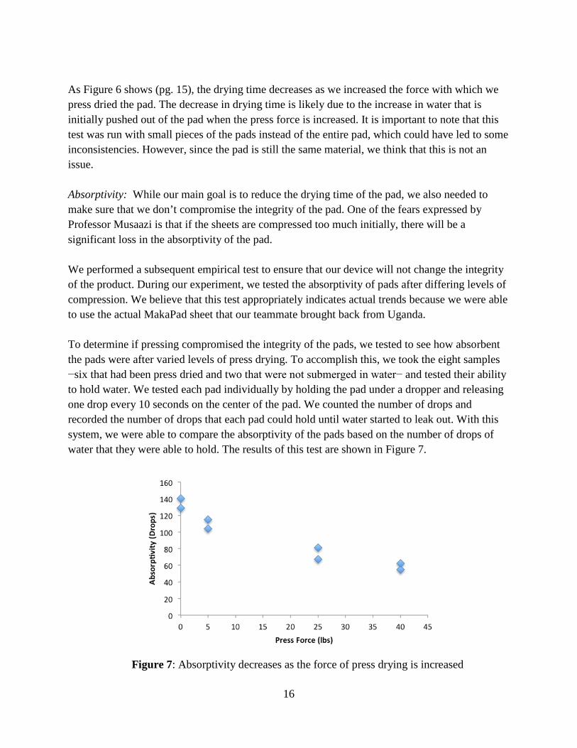
As Figure 6 shows (pg. 15), the drying time decreases as we increased the force with which we press dried the pad. The decrease in drying time is likely due to the increase in water that is initially pushed out of the pad when the press force is increased. It is important to note that this test was run with small pieces of the pads instead of the entire pad, which could have led to some inconsistencies. However, since the pad is still the same material, we think that this is not an issue. Absorptivity: While our main goal is to reduce the drying time of the pad, we also needed to make sure that we don’t compromise the integrity of the pad. One of the fears expressed by Professor Musaazi is that if the sheets are compressed too much initially, there will be a significant loss in the absorptivity of the pad. We performed a subsequent empirical test to ensure that our device will not change the integrity of the product. During our experiment, we tested the absorptivity of pads after differing levels of compression. We believe that this test appropriately indicates actual trends because we were able to use the actual MakaPad sheet that our teammate brought back from Uganda. To determine if pressing compromised the integrity of the pads, we tested to see how absorbent the pads were after varied levels of press drying. To accomplish this, we took the eight samples −six that had been press dried and two that were not submerged in water− and tested their ability to hold water. We tested each pad individually by holding the pad under a dropper and releasing one drop every 10 seconds on the center of the pad. We counted the number of drops and recorded the number of drops that each pad could hold until water started to leak out. With this system, we were able to compare the absorptivity of the pads based on the number of drops of water that they were able to hold. The results of this test are shown in Figure 7.
Figure 7: Absorptivity decreases as the force of press drying is increased
16

This test shows that the sheets that were press dried with more force are not able to absorb as much as the sheets that are allowed to air dry. We need to consider this when we design the acceptable press force range for our device so that we do not make the MakaPad less absorbent. There will be a tradeoff between the drying time and the absorptivity of the sheets and in the coming weeks we will need to analyze the trade-offs so that we can find an optimal solution. Durability: Despite a limited variety of materials available in Uganda, it is critical to assemble a press that will remain sturdy, reliant, and durable even with frequent use. Ultimate failure would result if one of the main components of the mechanism, such as the foot pedal or the pressing plates, were to break, because the drying process would come to a halt. In order to investigate potential failures, we used our knowledge of solid mechanics to perform a stress analysis on the mechanism. While performing a stress analysis, we determined which parts of the mechanism were likely to experience the greatest stress. We found these to be the arms connecting the foot pedal to the vertical beams attached to the press assembly, and the short pieces connecting the arms to the base of the press at the fulcrum point. For the arms, we calculated the maximum bending stress using Equation 1.
σMax = 𝑀𝑀𝑀𝑀𝐼𝐼
(Eq. 1) In this equation, M is the moment about the neutral axis, which is the product of the force, F, acting on the beam, and the distance at which the force is acting, y is the perpendicular distance to the neutral axis, which is the distance from the center of the pipe to the outer diameter, R, and
I is the second moment of inertia about the neutral axis for a thin-walled tube, 𝜋𝜋 (OD4−ID4)64
, where OD and ID are the outer and inner diameters of the pipe, respectively. We have selected 1-1/2 inch PVC pipe, which has an actual ID of 1.593 inches (40.4462 mm) and an OD of 1.9 inches (48.26 mm). In addition, our design utilizes an arm length, L, of 27 inches (685.8 mm). Although we expect the normal force applied to the foot pedal to be less than 15 lbs., we analyzed the behavior of the beam in a worst-case scenario, where the worker’s entire body weight was pressed on the beam, to ensure durability. In order to estimate this maximum force, F, that would be applied, we performed a simple experiment using a scale. We first measured our weight while standing still, with both feet on the scale. We then got off of the scale, and proceeded to step down onto it with 1 foot, simulating the motion that would be used to operate the press, and measured the maximum weight that was displayed on the scale. It was found that the maximum weight recorded during the step was about 10% greater than the stationary weight. We estimated the average weight of the Ugandan workers using the mechanism to be around 150 pounds (675 Newtons). After adding the 10% increase in weight during the worker’s step down
17

onto the pedal, we calculated a maximum applied force of about 165 pounds (742.5 N). A force diagram of this analysis can be seen in Figure 8.
Figure 8: A force diagram for calculating the maximum bending stress of the connector arm
Plugging these values into Equation 1 gave a maximum bending stress of 22.8 MPa in the arms. Our source from which we looked up the ultimate tensile stress of rigid PVC pipe gave a range of values from 34 to 62 MPa [22]. Taking the average of these values gave an ultimate tensile strength of 48 MPa. We were then able to calculate a safety factor of 2.1 for the arms under maximum loading, which is within an acceptable range for our purposes. In our design, the arm component is actually a combination of 2 separate pieces, fixed together by a tee-connector, rather than a single beam. We recognize that this stress analysis is not entirely accurate, and does not reflect this fact, however, since the 3 pieces are glued together with PVC cement, we have approximated the arm to be a single, rigid beam. We believe this approximation to be appropriate for our purposes. The small beam connecting the arm to the base of the mechanism at the fulcrum point, perpendicular to the arm, could also be analyzed in a similar fashion. Using Equation 1 again, where y and I remain the same, but changing M to reflect a pipe length of 3 inches (76.2 mm) and force of 742.5 N, resulted in a maximum bending stress of 10.1 MPa. Compared to the ultimate tensile strength of 48 MPa, a safety factor of 4.7 was calculated. This is also well within an acceptable range for our purposes. 10. RISK ANALYSIS In order to evaluate the various risks of our chosen design, our team utilized a failure modes and effects analysis (FMEA). We weighted each potential risk on a scale of 1-5 based on three factors: probability of occurrence, severity of risk, and likelihood of noticing this failure. A high weight in each of these respective categories represented a likely risk, a severe risk, and a low
18

chance of noticing the risk before it is too late to remedy the problem. We then multiplied each factor to get the total score; a high score represented the greatest risk, while a low score represented a relatively low risk. The results of this analysis are shown in Table 3 below.
Table 3: Failure Modes and Effects Analysis of chosen concept Potential Failure Mode
Consequence Cause of Failure Current Design Controls
Frequency of Occurrence
Severity of Risk
Likelihood of Noticing Risk
Total
Foot pedal breaking or cracking
Unable to lift the press
Excessive force Establish maximum force to be applied; reinforce with concrete
1 5 2 10
Press assembly fails
Pad quality compromised
Excessive compression force
Install hard stops to limit force; reinforce with concrete
1 5 2 10
Pinch points in press
Worker injury Hands/fingers caught in moving parts
Install guards and have a tight fit for the screens
3 3 1 9
Threads lock up
Press motion is constrained
Dirt entering through the threads
Sleeves around the threads
3 3 1 9
Screws/nails loosen
loss of stability and potential partial collapse
Vibration and stress accumulation
Multiple fasteners at critical connection points
1 3 3 9
Overexertion Health hazard Excessive labor Weighted foot pedal
2 1 3 6
Metal water collector corrosion
Health hazard Prolonged water exposure
Use of non-corrosive metal or plastic
1 1 5 5
Weather damage
Structural integrity compromised
Long exposure to sun
Use of PVC pipe to replace wood and coating the wood
1 2 1 2
Based on this FMEA, our team noticed that the biggest problems would occur due to failure of the PVC, with the foot pedal breaking and the press assembly failing both receiving scores of 10. This score was obtained because the severity of either component failing would be huge, causing the entire press to be useless until these pieces could be replaced. Fortunately, we think that this problem is not very likely to occur, since our team calculated a high safety factor for these pieces. Additionally, in Uganda, the pieces will be reinforced with concrete, further adding to the
19
already high safety factor. Also, we believe that these problems will be relatively easy to spot before they occur due to cracks appearing in the PVC. This will allow for early detection and allow for replacement parts to be readily on hand. 11. VALIDATION TESTING In order to verify that all of our requirements are met and that our mechanism functions as desired, we must perform validation testing. We have concluded that five major aspects of our mechanism need to be validated in order to get repeatable and reproducible results: drying time, water collection, absorptivity, force, and electricity. A series of different tests will be employed in order to validate each of these specific parameters. Drying Time To validate that we have met our requirement of a 30% reduction in drying time, we recreated the sheet making process. From Mario’s trip to Uganda, we have a large quantity of the paper and papyrus sheets, which allowed us to recreate the pulp with. To do that, we soaked the existing sheets in water, and then mixed them until they broke apart and formed a pulp. Our next step was to make a sheet of paper using the mesh screens from Uganda, and press drying the sheet on our device. The sheet was allowed to finish air drying, and we then recorded the time that elapsed until the paper was dry to the touch. We then compared this time to the time of a sheet that was allowed to dry without being pressed and we found that the press introduced a 40% reduction in dry time. Water Collection We were able to verify that our machine collects 50% of water by press drying some of our recreated pads. Our water collection method catches all of the excess water and the only water that can’t be reused is the water that evaporates on the metal gutter. We are confident that we collected 90 percent of the water. Absorptivity In order to test the absorptivity of our pads we took the dried sheet and placed them on the mesh above a bowl. Water was then dropped onto the center of the pad and we counted how many drops it took until water began to leak out of the bottom of the pad. We used the number of drops absorbed as a metric for how absorbent the pads were. Our pressed pad was slightly less absorbent than the pad that wasn’t pressed but we are confident that this different will not be an issue for the MakaPad.
20
Force We wanted to make a device that didn’t require the worker to exert themselves too much, so for this reason we wanted to keep the input force less than 15 lbs. To test that we meet our force requirement, we used a scale to measure how hard the worker needs to push. The results of our test show that when the foot pedal is filled with concrete the worker will need to press with 14.8 pounds of force. Electricity One of the engineering specifications that drove our design was our goal of using no electricity. Our device will be completely powered by the force of a human, so it will not require any electricity and doesn’t require any subsequent testing. 12. DISCUSSION 12.1 DESIGN CRITIQUE The final design was successful and all engineering requirements were met including decrease in drying time, water recollection, and operation without electricity. The design was able to be constructed with relative ease due to our material selection of PVC as the primary building material and can be reasonably accomplished on-site in Uganda. A difficulty encountered was achieving proper tolerances in the assembly. Due to the nature of the PVC joints we used to assemble our mechanism, individual part tolerances were fairly generous, allowing fine tuning of dimensions by controlling how far pipes were pushed into joints when they were glued. However, the finality of PVC cement makes adjusting pieces after assembly impossible, whereas with wood, for example, pieces can typically be unscrewed and replaced modularly. When assembling the sliding press mechanism, the vertical guide rails were assembled with all the pieces at the right distances but were glued in a way that was slightly angled outwards and not completely vertical. This brought about problems with the sliding mechanism causing the fit to be too narrow at the bottom and too wide at the top. Because the angle of the vertical supports could not be corrected without reconstructing the entire support structure, this was corrected by reconstructing the sliding press structure to fit this misalignment. Although this largely eliminated the problem, if a similar issue were to arise elsewhere in the structure, it would be much more difficult to correct and would necessitate the purchase of extra parts and possibly redoing the majority of the structure. 12.2 FUTURE WORK With more time and resources, load bearing structures of the design including the four support legs and the foot press would be filled with cement to increase rigidity and robustness of the design and would allow for better evaluation of the power needed to effectively power the mechanism. Additionally, methods of shielding the threaded joints from dust and debris to
21

ensure continued smooth operation would be investigated. The solution to this could be as simple as a fabric sleeve being attached around each joint. In the coming weeks, the final design will be built and tested on site in Uganda and will face working in the actual manufacturing process for the first time. The suggested future work detailed above will likely be implemented as well. The design will be evaluated and plans for additional further improvements will be assessed at that time.
22

REFERENCES [1] Uganda. Petaluma, Calif.: World Trade Press, 2010. [2] Lee, Seung, and Brad Kerner. "What Do Menstruating Girls Need In Schools?" A Global Village 8.9 (2013): 30-33. A Global Village. Jan. 2013. Web. 22 Jan. 2015. [3] Dusabe, Cyprian. "Affordable Sanitary Pads For 1500 Ugandan Girls." GlobalGiving.org. St. Mark Institute Of Health Science, n.d. Web. [4] Dolan, Catherine. "A Blind Spot In Girls' Education: Menarche and Its Webs of Exclusion in Ghana." Journal of International Development (2013): 1-15. Print. [5] "Sanitary Pads Keep Ugandan Girls in School." GlobalGiving.org N.p., n.d. Web. [6] Onchiri, Sheba. "The Implications of the 2003 Free Primary Education Policy for Girls' [7] "MakaPads." MakaPads. Teach for Tomorrow, n.d. Web. 12 Jan. 2015. [8] MAKAPADS. Dir. Francois Vaxelaire and Sara Fusco. Focus Forward Films, 2012. [9] Mahoney, Kathryn. "Papyrus and Scrap Paper: A Monthly Blessing for Refugee Women in Uganda." UNHCR News. United Nations, 14 Mar. 2013. Web. 27 Jan. 2015.54-55. Print. Ann Arbor: ProQuest. Web. 21 Jan. 2015.Educational Opportunities in Kenya: A Case Study of Girls Attending Public Schools inKisii District, Western Kenya." Order No. 3557480 Michigan State University, 2013. pp. [10] Ellis, Amanda, and Clare Manuel. Gender And Economic Growth In Uganda: Unleashing the Power of Women. Washington, D.C.: World Bank, 2005. [11] Okwudire, C., 15 January, 2015, Interview, Ann Arbor, MI, US. [12] Musaazi, M., 26 January, 2015, Interview (Skype), Ann Arbor, MI, US. [13] Buchanan, Leigh. "This Man Can't Stop Innovating." Inc. N.p., 01 May 2012. Web. 26 Jan. 2015. [14] Kannatey-Asibu, E., 15 January, 2015, Interview, Ann Arbor, MI, US. [15] Manual Dryer. 李孝�, assignee. Patent CN 201581269 U. 15 Sept. 2010. Print. [16] Caps, Arthur W. Drying Press. Photostat Corp, assignee. Patent US1665403 A. 10 Apr. 1928. Print. [17] Anderson, David N. Fruit Juice Extraction Press. Fmc Corporation, assignee. Patent EP0501185 B1. 9 Aug. 1995. Print. [18] Hayward, Ralph A. Apparatus for Drying Paper, Paperboard, Pulp, and the like. Kalamazoo Vegets Le Parchment, assignee. Patent US2532910 A. 5 Dec. 1950. Print. [19] Scherb, Thomas T., Jeffrey Herman, and Luiz C. Silva. Method of Dewatering a Fibrous Web with a Press Belt. Voith Paper Patent GmbH, assignee. Patent 7,351,307. 1 Apr. 2008. Print. [20] "Uganda: Sanitary Project Changes Refugees' Lives." IRIN Africa (2010): 1-4. Web. [21] Bartneck, Brandon, Monya Bransky, Ian Fitzner, and Sam Greenwood. "MakaPad Production Optimization: Drying." (2014): 6. Print. 10 Feb. 2015. [22] “PVC Strength”, PVC.org. (n.d.). Retrieved February 25, 2014, from http://www.p-vc.org/en/p/pvc-strength [24] The Home Depot. (n.d.). Retrieved February 25, 2014, from http://www.homedepot.com/s/2x4?NCNI-5 [25] Webstaurant Store. (n.d.). Retrieved February 25, 2015, from http://www.webstaurantsto-re.com/?gclid=CKy_q8ib_sMCFQTKtAodE1sAeQ
23

AUTHORS Mario Arjona
I was born and raised in Pittsburgh, PA and am an avid Penguins fan. In May 2015, I will graduate with a BS in Mechanical Engineering and a Certificate in Entrepreneurship. I have had an unforgettable four years at Michigan, enjoying my time as a part of Delta Tau Delta Fraternity and serving as Co-President of BLUElab NicarAGUA for 2 years. After graduation, I will be going professional in something which, until recently, has only been an amateur pursuit of mine: snack making. I will be starting my career with General Mills as a Manufacturing and Engineering Associate at a Yoplait and Pillsbury plant just outside Nashville, TN. Looking forward, I hope to continue to apply my engineering skills and eventually manage national and global engineering projects in the consumer products manufacturing industry. Matt Meisel
I have lived in Michigan my entire life, having grown up in Howell, about 30 miles north of Ann Arbor. My parents knew around age 5 that I would grow up to be an architect or some sort of engineer simply because of my love of putting things together. Needless to say, my basement was full of Legos and K’NEX as a kid. After four years of headaches and all-nighters, I will conclude my undergraduate education in May of 2015, while receiving a BS in Mechanical Engineering. While I don’t know exactly what I want to do yet, I am developing a liking for the oil production industry, and hope to move south in pursuit of a job.
24
Peter Warendorf
I was born in New Jersey but I have spent the majority of my life living in Seattle, WA. I am a big sports fan and I try to play and watch as much baseball, basketball and football as I possibly can. I plan to graduate with a degree in Mechanical Engineering in May 2015. I have enjoyed my four years at Michigan and all of the new experiences but I am also excited to start working after graduation. I hope to find a job in a new city where I can gain work experience and meet new people. Noam Zimet
I am an enthusiastic mechanical engineering student with a passion for helping the environment. My ideal career would involve helping the world continue its trend of switching to alternative energy sources and helping businesses become more energy efficient. An Ann Arbor native, I have enjoyed the experience of staying near family for an additional four years while at UM before moving away to start work. While at UM, I have enjoyed many days of Frisbee on the Diag as well as swing dancing every Thursday night at North Quad.
25
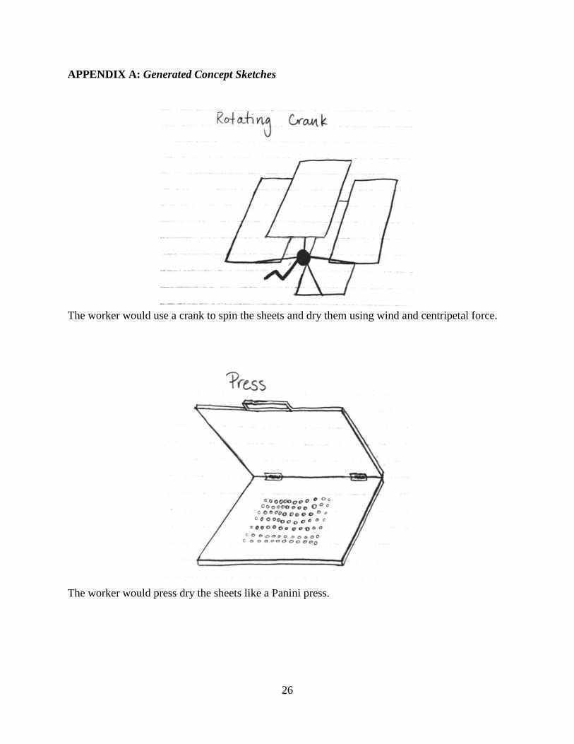
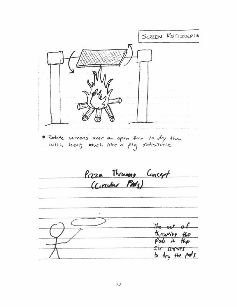
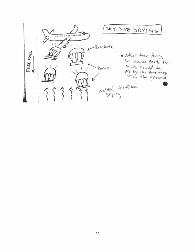
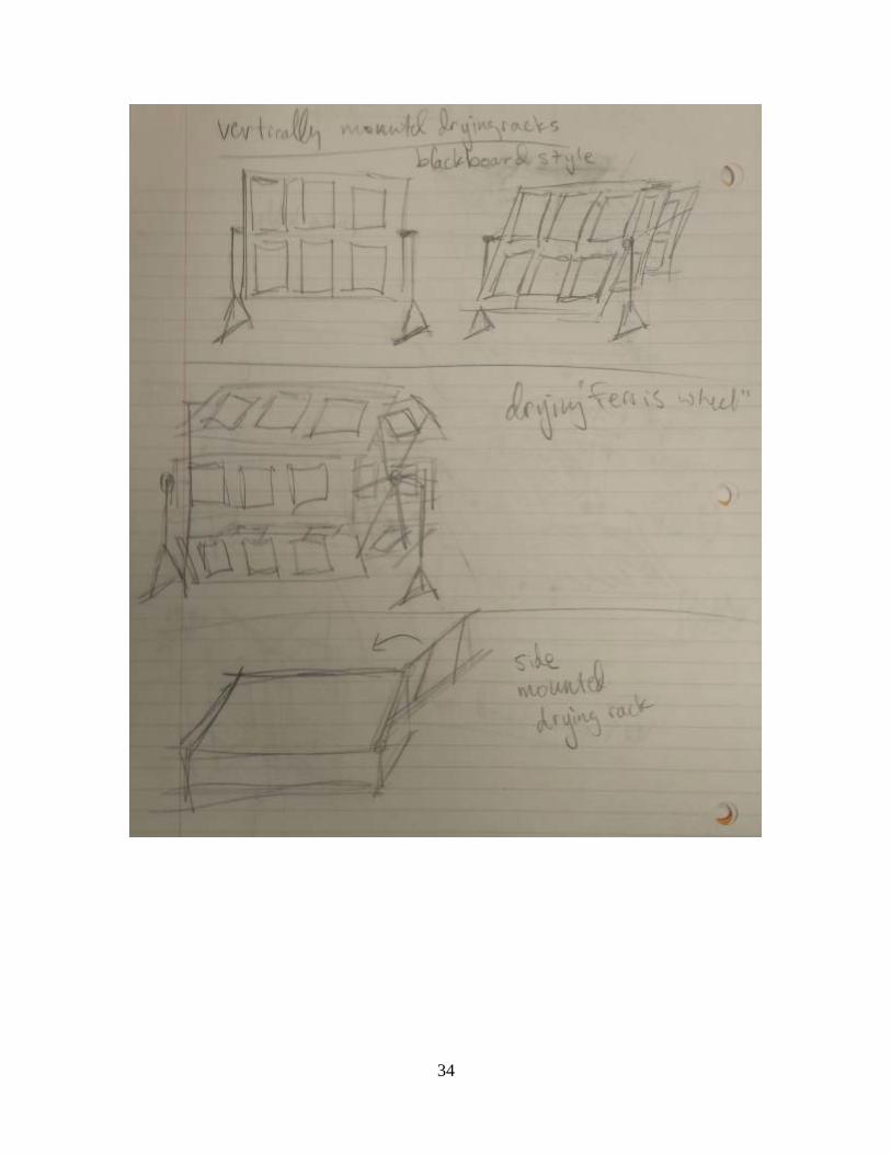
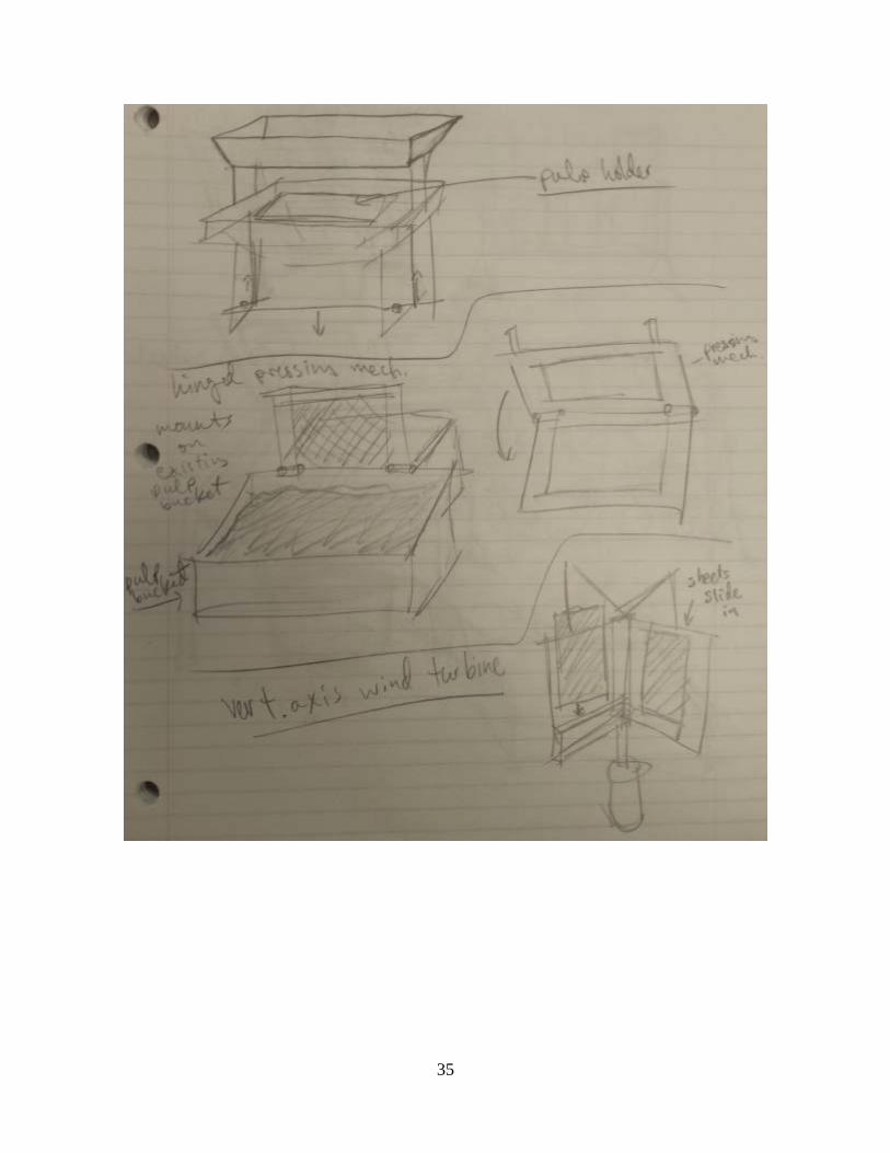
APPENDIX A: Generated Concept Sketches
The worker would use a crank to spin the sheets and dry them using wind and centripetal force.
The worker would press dry the sheets like a Panini press.
26

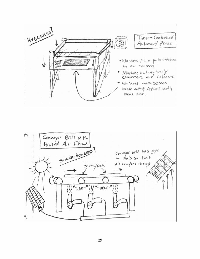
This would act like a conveyor belt with a rolling pin to squeeze out the excess water.
The worker would press down the top and the air pressure in the box would squeeze out water.
27
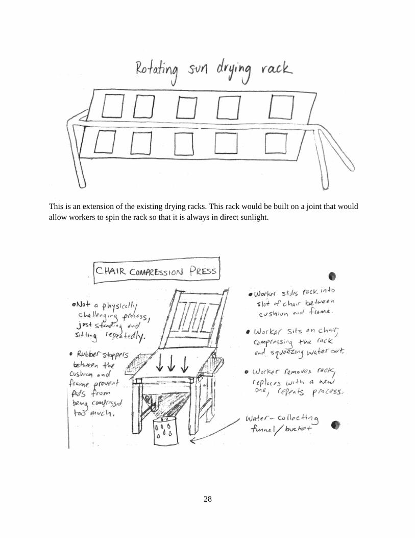
This is an extension of the existing drying racks. This rack would be built on a joint that would allow workers to spin the rack so that it is always in direct sunlight.
28
29

30

31
32
33
34
35

36
37
APPENDIX B: Previous Semester’s Design
38

APPENDIX C: Personal Statements C.1 ENVIRONMENTAL IMPACT Mario Arjona One of the biggest constraints placed on our project was the use of locally available materials and locally feasible manufacturing processes for reproduction of our design in Uganda. Originally, our plan was to use wood for the majority of construction as it is locally available as well as easy to work with. After taking a trip to Uganda to meet with the workers and get to know better their system and how they work, the decision was made to switch to PVC construction. The use of PVC is something they have used in Uganda to allow the construction of robust structures that are impervious to water damage and can be reinforced with concrete to make them incredibly strong and sturdy. Although the use of PVC is something that came directly from Uganda, it does bring up more issues of environmental consideration that may not have been weighed out before their use in Africa. PVC is widely recognized as a plastic that has significant negative effects on the environment. It uses harmful chemicals during its production and is very difficult to recycle a useful amount of it. Our reasoning for using PVC despite these issues is that it is still the standard in plastic piping and its pipes and fittings are widely available worldwide, even in low resource areas, where they are used for construction and piping. Although it may not be an ideal material. Matt Meisel An important aspect of engineering that must be considered in any given project is the type of materials and processing used, and what impacts it has on the environment. Although a material may be harmless to the environment on its own, the way in which it is processed may have detrimental effects which outweigh the benefit of the material being benign. The opposite can be true as well, where the processing required to produce a material is relatively environmentally friendly, but its product is not. This was especially true for our project. Our choice of material for the pressing mechanism was PVC pipe. Although PVC has wonderful advantages in comparison to other common building materials, such as strength, weight, durability, and cost, it is absolutely awful for the environment and also human health. When burned, PVC pipe releases hydrogen chloride, which can cause respiratory damage, and dioxin, which is the most dangerous man-made carcinogen. Even if it isn’t burned, PVC still contains hazardous materials, such as vinyl chloride, that can also have adverse effects on health. Focusing more on the environmental aspect rather than the human health aspect, PVC is a nightmare for the environment. Due to the unique characteristics that make up PVC pipe, it is not easily disposed of. As PVC does not decompose. As mentioned above, it cannot be incinerated due to the toxic gases that would be released. That really only leaves one option for unwanted PVC pipe: disposal in landfills. Techniques are being developed in an effort to recycle PVC, but they are proving to be costly, time consuming, and inefficient.
39
When selecting a material for our project, significant importance was placed on using locally available materials in Uganda, where we hope the press will be replicated. We certainly could have used more environmentally friendly materials such as wood or metal, but we concluded that we were justified in using PVC since we would be using such a relatively low amount, in comparison to companies that use PVC on a very large basis. That being said, even though it would be bad for the environment to deposit the PVC pipe in a landfill once Professor Musaazi is finished with it, I think the low quantity softens the blow a bit. Weighting the use of locally available materials as high as we did almost handcuffed us into using PVC, as no other materials are as widely available and cheap in Uganda, but using our ethical judgement made us feel better about selecting PVC for our material. The only “fix” we could make would be to use a more expensive material that is better for the environment, but that is undesirable. Peter Warendorf Probably the biggest environmental issue that we struggled with was in the use of PVC. PVC is a nasty material that can’t be recycled. Another negative of PVC is that when it is melted, it can become dangerous. While the environmental impacts are not great, it is much stronger than wood when exposed to water. This was one of the tradeoffs that we had to make. If we used wood, then it would be overall healthier and better for the environment, but it wouldn’t last as long as PVC, so we would waste much more material. While our machine is very unlikely to ever be recycled, our hope is that it works well enough and long enough to make the negatives at least tolerable. One of the positives of our design is that it collects almost all of the excess water during the drying process. Our sponsor made it clear to us that water recollection would be a great bonus to our design, so we made it happen. During the dry season in Uganda, water can be less accessible than in the rainy season so with our recollection device they will be able to reuse most of the water. This will not only cut down on the costs for them to operate the production facility, but it is always a positive when materials can be recycled. In our case, the water that we collect can be taken and put back into the initial pulp mixture. The fact that our press doesn’t use electricity is another positive for the environment. All of the motion is powered by the leg of the operator which allows the drying process to use zero total electricity. Electricity in Uganda is very expensive, so not only does our press make production cheaper, but it also reduces the negative environmental impact of MakaPad production. Noam Zimet As with all engineering projects, it is important that our team consider the environmental impacts of our project. The main adverse impacts come from the choice of materials, the transportation used to get the materials from one place to another, and the scale of our project, the biggest of these impacts coming from using PVC as our main building material. Our team recognizes that PVC is not environmentally friendly, being composed of materials that Greenpeace has identified as being carcinogenic and harmful to the natural environment. Since
40
PVC is created from chlorine, it releases chlorine-based toxins that accumulate in the environment. This problem has been linked to a variety of health problems for which our team would rather not be partly responsible. It is unfortunate that we were only asked to evaluate these impacts at the end of the semester or else our team could have potentially chosen a more environmentally-friendly material. The one positive note for our team choosing to use PVC, environmentally speaking, is that it is one of the most common manufactured plastics in the world, and our project is on such a small scale that it will have an absolutely negligible impact on total PVC production and environmental impacts. Additionally, the main reason our team chose to use PVC is because it is a locally-available water-resistant material. If we were to use wood instead, we would have to chemically-treat it to become water-resistant, causing perhaps lessened but still similar environmental concerns. The other issue that we have to consider is the energy emissions used in transporting the material from production plants to where we are actually building the design, whether it is building a prototype here in the US to building the actual design in Uganda. Since the main production facilities for PVC are located in Southern US, we have to consider the large amount of fuel necessary to transport the material from the south to Michigan. Similarly, we would have to consider the fuel necessary to transport the material to Uganda from the nearest PVC production plant. However, as with the consideration for PVC as our building material, the environmental impacts of this transportation are relatively small due to the small scale of our project and the relatively little amount of material required in our design compared to typical PVC piping use. Therefore, although it has been necessary for PVC to have been transported and for fuel to have been burned for this, our group’s individual contribution is very small due to the proportionally tiny amount of PVC used in our project. C.2 ETHICS OF DESIGN Mario Arjona Working on the MakaPad drying project gave our team an opportunity to tackle a unique challenge balancing engineering as well as human considerations. While almost every engineering problem requires addressing both of these aspects of design, the MakaPad project, which will be implemented in rural Uganda, makes it our responsibility to thoroughly understand the needs of a foreign culture under circumstances that are vastly different than what we are used to in our daily lives. These differences impose constraints that supercede even engineering requirements. The human considerations in our case heavily affected our choice of materials, manufacturing processes, and, most importantly, operation of our mechanism by the user. As a continuation project, we had the advantage of seeing the results of previous teams faced with the same challenge. We saw that, even if a design meets engineering requirements, these human factors determine whether or not the design is ultimately accepted by the end user. Throughout the course of our design process, these differences in approaches to innovation became apparent very often. My trip to Uganda to meet and interact with these workers helped me see these differences firsthand and get a better understanding of how they think and work. What I learned certainly changed my thinking approaching our design. As a part of a modern technological culture that highly values incremental changes we believe make our lives easier,
41

we had to suppress urges to settle for changes to our design that we identified as acceptable but may not be seen that way in Uganda. The workers in Uganda tend to put the most value on tradition and what they know to be tried and true. Bringing about changes in the way they do things requires them to see the value of the change very clearly and how its effect is justified. An example of this came up in the design of our foot pedal that operates our mechanism. We did tests of operation using different lever arm lengths that changed the height of the pedal, the travel distance of the press, and the mechanical advantage of our machine. We noted that having a higher pedal position of about 11” and a mechanical favorable mechanical advantage for force transfer made operation relatively easy and comfortable for us and left a comfortable clearance to place the pulp sheets in between the pads. However, we realized what we think is comfortable is probably not best in the eyes of the Ugandan women who will be operating the machine. When analyzing the press again, we put an emphasis on overall simplicity of the mechanism. The workers probably won’t understand or appreciate the mechanical advantage of our machine, what they will understand is its effects: force and distance required to push the pedal and the clearance it leaves for placement and retrieval of the pulp sheets. Having this in mind, we set new goals of minimizing the foot pedal travel distance and maximizing the clearance between the press pads while keeping the required force comfortable for repeated use. The end result was a foot pedal height of 7.5”, the height of a standard stair, requiring a travel distance of only 4” translating to a clearance of 6” for pad placement, while still requiring under 20 lbs. of force to press. A more straightforward example was our change of plan from using wood, which is easy to work with, to PVC, which is as readily available but is resistant to water and can be reinforced with concrete (a trick they use in Uganda) to make it more robust. Matt Meisel As an engineer, one of our most important responsibilities is to be ethical. To me, being ethical is a philosophical belief that choosing right over wrong is a moral obligation, with no exceptions. The engineering industry presents many opportunities for an individual to make unethical decisions, such as concealing test results that deem a failure of a part, or using insufficient materials in an effort to cut costs. Since our actions can have dire consequences, often times involving human lives, it is of utmost importance to always be straightforward with our decisions and findings, no matter the repercussions. Our team kept this mentality throughout the duration of our project, and made all of our decisions with ethics in mind. While our project does not possess much of a threat for catastrophe, unlike a bridge or an airplane, we were still presented with instances in which unethical decisions could have been made. Since our project is a continuation project, and this is the third iteration of it, we very well could have simply used a combination of characteristics from the previous two mechanisms, and put little thought into a new or improved design. Instead, we initially did not consider the two previous semesters’ designs at all, in order to maximize the potential for a new idea. As it turns out, the press idea from last semester ended up being the best choice for us, but we still approached the problem ethically. In addition, we could have easily fabricated our empirical test results, but instead we chose to act in an ethical manner, and performed the proper testing. An example of this came about during
42

the empirical testing that related the pad absorptivity to the amount of force that it was pressed with. The workers in Uganda performed a test to determine the relationship, if any, between these two parameters. After completing their test, they reported that there was no relationship between absorptivity and force, and that the pad’s absorbing capability was not affected by force. In an unethical manner, our team could have simply taken their word for it and agreed with these results, but instead we performed the same test and found there was a relationship. Had we acted unethically, we would not have caught this, and potentially set us up for a lot unexpected results, and many headaches. The Code of Ethics has indeed been followed by our team during the planning, building, and testing phases of our final mechanism. While some aspects of the Code didn’t really apply to our group/project, such as issuing public statements or avoiding conflicts of interest, we implemented all other aspects that did, particularly performing services in our areas of expertise, and keeping safety paramount. Peter Warendorf While we were designing our press, we wanted to make sure that we were ethical in everything that we did and in every decision that we made. One of the big issues with our project was that it needs to be produced in Uganda, and this presented us with some unique challenges. We wanted to design the best possible product, but with the materials that were available on site. The easiest way for us to combat this problem would have been to simply ignore the issue and make the press out of the best possible materials, regardless of the cost in Uganda. We made the ethical decision and chose to use PVC pipe. We knew that PVC was available, but it isn’t as good as some of the other materials that we could have selected, so we needed to come up with a way to strengthen it or risk failure. Again, we were faced with a problem where if ignored could result in the eventual failure of our press and possible harm to the worker. We had to look into ways to strengthen the PVC so that the machine would be safe for the workers and we found the idea of filling the supporting structure with concrete. While it was the ethical decision to fix the problem that could possibly harm a worker, in this case we actually were able to come up with a really good remedy and we didn’t even have to sacrifice much more than the weight of our device. One ethical dilemma that we faced throughout our design was the choice between taking the easy path or putting in more effort to get a better product. While some people may think that we took the easy way out because of our use of PVC, we actually chose to make it out of whatever would be easiest for the user. Wood, for example, would have been much easier to assemble but it wouldn’t have lasted as long in weather. Noam Zimet It is paramount for engineers to be ethical in their designs because engineers are entrusted with the power to design structures and mechanisms that affect people on a daily basis. If mechanical engineers working on cars, for example, acted unethically and proposed ideas that were not experimentally valid, it could result in unnecessary and tragic deaths of consumers. An excellent
43
and unfortunate example of this was the GM ignition switch recall fiasco, which could have been prevented had the proper measures been taken and people stepping up and admitting that there was a fault in the design. Noting this importance in being ethical, our team strived to perform to be ethical in our design as well. Looking through the Code of Ethics for Mechanical Engineers, I found that our team has satisfactorily followed the guidelines. We have not taken any money from two companies at once (or even money from one company, for that matter); we have not tarnished the reputation of engineers or the engineering society; we have not shared any proprietary information with others that could lead to the downfall of our sponsor’s company. We also acted ethically when performing our initial engineering analysis. Even though at the time, we lacked access to MakaPads and could not perform tests with the actual pads, our team did our best to reproduce the consistency of MakaPads by creating a pulp mixture from paper and water. We performed our initial analysis with this mixture and obtained good results, which would lead to us believing that our press mechanism will work satisfactorily. However, in the theme of acting completely ethically, our team plans to replicate our tests with actual MakaPads now that Mario has brought some back from Uganda. This will ensure that our tests are completely accurate and representative of the situations that will be present in the production process in Uganda.
44

APPENDIX D: Materials and Manufacturing Plans D.1 MANUFACTURING PLANS Our manufacturing process was fairly simple because of the narrow selection of materials and machining processes available to use in Uganda. Our main task was to cut all of the PVC to the correct lengths in order to assemble the mechanism. We wanted our device to be able to be replicated in Uganda, so we needed to take their ability for manufacturing into account when we were creating our concept. We believed that because the only manufacturing necessary was cutting PVC to length and drilling holes, they would be able to do this using a drill and a handsaw, which we assumed are available in Uganda. The only nontrivial part to manufacture is the water collection trough, which can be manufactured offsite in Uganda using three simple bends. A summary of our manufacturing plan for the frame of the press is presented in Table D.1.1. Table D.1.2 details the manufacturing process of the water collection trough. Table D.1.3 explains the manufacturing processes of the polyethylene board on the press assembly.
Table D.1.1: Manufacturing process of our final design
Step #
Process Description Machine Fixtures Tools
01 Cut PVC pipe to length Handsaw
02 Drill holes in PVC on the stationary top press for attachment of aluminum pressing boards
Drill Vise Drill bit
Table D.1.2: Manufacturing process of water collection trough
Step # Process Description Machine Fixtures Tools
01 Shear aluminum sheet metal to size (36” x 31”)
Shearing Machine
02 Measure in 1” in from the side at one end, and draw a line to the corner of the other end on the same side. Repeat for the other side. Shear piece along these lines
Shearing Machine
Tape Measure, Sharpie
03 Locate the middle of the piece in the width direction (17.5” from side) and draw center line down the middle
Tape Measure, T-Square, Sharpie
45

04 Draw line from the corner of the narrower end of the sheet, parallel to the center line. Repeat for other side.
T-Square, Sharpie
05 Bend along center line at a 30° angle
Hand Brake
Angle Finder
06 Bend along side lines at a 75° angle
Hand Brake
Angle Finder
Table D.1.3: Manufacturing process of polyethylene board for press assembly
Step # Process Description Machine Fixtures Tools
01 Measure out array of dots, separated by 1” in each direction
Tape Measure, Sharpie
02 Drill hole at each dot Drill Vise ¼” drill bit
46

D.2 BILL OF MATERIALS The bill of materials for this project are largely limited by the materials available in Uganda for local production of our final concept. In this bill of materials, prices were listed for building the project in Michigan, with prices found from Home Depot. When building the prototype in Uganda, team members will bring supplies from Home Depot, so this should be a relevant number. This bill of materials is summarized in Table D.2 below.
Table D.2: Bill of materials for our final design
47

APPENDIX E: Engineering Drawings
Figure E.1: Sample engineering drawing of 1.5” PVC pipe. The design uses many different lengths of PVC pipe with the same diameter; thus, length is not specified in the drawing
48

Figure E.2: Engineering drawing of 1.25” PVC pipe. The design uses many different lengths of PVC pipe with the same diameter; thus, length is not specified in the drawing
49