draft safety manual maxflo 3 - flowserve · · 2017-03-103.4 design verification 5 ... (1.4 to...
TRANSCRIPT
DRAFT
Safety Manual – MaxFlo 3 Flowserve
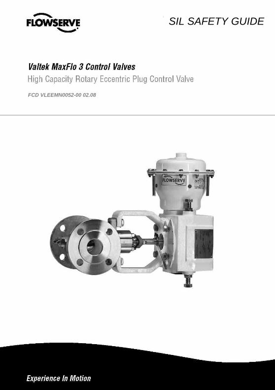
SIL SAFETY GUIDE
FCD VLEEMN0052-00 02.08
Table of Contents
1. Introduction 3
1.1 Terms and Abbreviations 3
1.2 Acronyms 4
1.3 Product Support 4
1.4 Related Literature 4
1.5 Reference Standards 4
2. MaxFlo 3 Device Description 5
3. Designing a Safety Instrumented Function using a Flowserve MaxFlo 3 5
3.1 Safety Function 5
3.2 Environmental limits 5
3.3 Application limits 5
3.4 Design Verification 5
3.5 SIL Capability 6
3.6 Connection of the MaxFlo 3 to the SIS Logic-solver 6
3.7 General Requirements 6
4. Installation and Commissioning 8
4.1 Installation 8
4.2 Physical Location and Placement 8
4.3 Pneumatic Connections 8
5. Operation and Maintenance 8
5.1 Proof test without automatic testing 8
5.2 Proof test with automatic partial valve stroke testing 9
5.3 Repair and replacement 9
5.4 Useful Life 9
5.5 Flowserve Notification 9
1. Introduction
This Safety Manual provides information necessary to design, install, verify and maintain a Safety Instrumented Function (SIF) utilizing a Flowserve MaxFlo 3 Valve and Diaphragm Actuator. This manual provides necessary requirements for meeting the IEC 61508 or IEC 61511 functional safety standards.
1.1 Terms and Abbreviations
Safety:
Freedom from unacceptable risk of harm
Functional Safety:
The ability of a system to carry out the actions necessary to achieve or to maintain a defined safe state for the equipment / machinery / plant / apparatus under control of the system
Basic Safety:
The equipment must be designed and manufactured such that it protects against risk of damage to persons by electrical shock and other hazards and against resulting fire and explosion. The protection must be effective under all conditions of the nominal operation and under single fault condition
Safety Assessment:
The investigation to arrive at a judgment - based on evidence - of the safety achieved by safety-related systems
Fail-Safe State:
State where solenoid valve is de-energized and spring is extended
Fail Safe:
Failure that causes the valve to go to the defined fail-safe state without a demand from the process
Fail Dangerous:
Failure that does not respond to a demand from the process (i.e. being unable to go to the defined fail-safe state)
Fail Dangerous Undetected:
Failure that is dangerous and that is not being diagnosed by automatic stroke testing
Fail Dangerous Detected:
Failure that is dangerous but is detected by automatic stroke testing
Fail Annunciation Undetected
Failure that does not cause a false trip or prevent the safety function but does cause loss of an automatic diagnostic and is not detected by another diagnostic.
Fail Annunciation Detected:
Failure that does not cause a false trip or prevent the safety function but does cause loss of an automatic diagnostic or false diagnostic indication
Fail No Effect:
Failure of a component that is part of the safety function but that has no effect on the safety function
Low demand mode:
Mode, where the frequency of demands for operation made on a safety-related system is no greater than twice the proof test frequency
1.2 Acronyms
FMEDA Failure Modes, Effects and Diagnostic Analysis
HFT Hardware Fault Tolerance
MOC Management of Change: These are specific procedures often done when performing any work activities in compliance with government regulatory authorities
PFDavg Average Probability of Failure on Demand
SFF Safe Failure Fraction, the fraction of the overall failure rate of a device that results in either a safe fault or a diagnosed unsafe fault.
SIF Safety Instrumented Function, a set of equipment intended to reduce the risk due to a specific hazard (a safety loop).
SIL Safety Integrity Level, discrete level (one out of a possible four) for specifying the safety integrity requirements of the safety functions to be allocated to the E/E/PE safety-related systems where Safety Integrity Level 4 has the highest level of safety integrity and Safety Integrity Level 1 has the lowest.
SIS Safety Instrumented System – Implementation of one or more Safety Instrumented Functions. A SIS is composed of any combination of sensor(s), logic solver(s), and final element(s).
1.3 Product Support
Please refer to the back cover for your regional Flowserve contact details.
1.4 Related Literature
Hardware Documents:
Valtek MaxFlo 3 Control Valve Installation, Operation and Maintenance Instructions
Valtek MaxFlo 3 Control Valve Brochure
Guidelines/References:
Safety Integrity Level Selection – Systematic Methods Including Layer of Protection Analysis, ISBN 1-55617-777-1, ISA
Control System Safety Evaluation and Reliability, 2nd Edition, ISBN 1-55617-638-8, ISA
Safety Instrumented Systems Verification, Practical Probabilistic Calculations, ISBN 1-55617-909-9, ISA
1.5 Reference Standards
Functional Safety
IEC 61508: 2000 Functional safety of electrical/electronic/ programmable electronic safety-related systems
ANSI/ISA 84.00.01-2004 (IEC 61511 Mod.) Functional Safety – Safety Instrumented Systems for the Process Industry Sector
2. MaxFlo 3 Device Description The MaxFlo 3 control valve and diaphragm actuator is a high performance, eccentric rotary plug design, which is used in low-pressure, high CV applications. The double-offset eccentric plug rotates into the seat at an angle that eliminates sliding over the seat surface. Fluid assists the plug to fail-open or fail-closed upon air failure. The diaphragm rotary actuator is a rugged single-acting actuator. It operates with air supply pressure from 20 to 60 psi (1.4 to 4.0 bar) and is field-reversible. The MaxFlo 3 control valve with diaphragm actuator is rated for ANSI/FCI 70.2 Class IV (Metal Seat). ANSI Class VI shutoff is obtained using the soft seat design.
3. Designing a Safety Instrumented Function using a Flowserve MaxFlo 3
3.1 Safety Function
When de-energized, the MaxFlo 3 moves to its fail-safe position. Depending on the version specified Fail – Closed or Fail - Open, the MaxFlo 3 will rotate the valve plug to close off the flow path through the valve body or open the flow path through the valve body.
The MaxFlo 3 is intended to be part of final element subsystem as defined per IEC 61508 and the achieved SIL level of the designed function must be verified by the designer.
3.2 Environmental limits
The designer of a SIF must check that the product is rated for use within the expected environmental limits. For SIL rated valves the minimum operating temperature is -40°F/-40°C , for other environmental limits refer to the Valtek MaxFlo 3 Control Valve Technical Bulletin.
3.3 Application limits
The materials of construction of a MaxFlo 3 are specified in the Valtek MaxFlo 3 Control Valve Technical Bulletin. It is especially important that the designer check for material compatibility considering on-site chemical contaminants and air supply conditions. If the MaxFlo 3 is used outside of the application limits or with incompatible materials, the reliability data provided becomes invalid.
3.4 Design Verification
A detailed Failure Mode, Effects, and Diagnostics Analysis (FMEDA) report is available from Flowserve. This report details all failure rates and failure modes as well as the expected lifetime.
The achieved Safety Integrity Level (SIL) of an entire Safety Instrumented Function (SIF) design must be verified by the designer via a calculation of PFDavg considering architecture, proof test interval, proof test effectiveness, any automatic diagnostics, average repair time and the specific failure rates of all products included in the SIF. Each subsystem must be checked to assure compliance with minimum hardware fault tolerance (HFT) requirements. The exida exSILentia
® tool is recommended for this
purpose as it contains accurate models for the MaxFlo 3 and its failure rates.
When using a MaxFlo 3 in a redundant configuration, a common cause factor of 5% should be included in safety integrity calculations.
The failure rate data listed the FMEDA report is only valid for the useful life time of a MaxFlo 3 valve. The failure rates will increase sometime after this time period. Reliability calculations based on the data listed in the FMEDA report for mission times beyond the lifetime may yield results that are too optimistic, i.e. the calculated Safety Integrity Level will not be achieved.
3.5 SIL Capability
3.5.1 Systematic Integrity
The product has met manufacturer design process requirements of Safety Integrity Level (SIL) 3. These are intended to achieve sufficient integrity against systematic errors of design by the manufacturer. A Safety Instrumented Function (SIF) designed with this product must not be used at a SIL level higher than the statement without “prior use” justification by end user or diverse technology redundancy in the design.
3.5.2 Random Integrity
The MaxFlo 3 is a Type A Device. Therefore based on the SFF between 60% and 90%, when the MaxFlo 3 is used as the only component in a final element subassembly, a design can meet SIL 2 @ HFT=0.
When the final element assembly consists of many components (MaxFlo 3, solenoid, quick exhaust valve, etc.) the SIL must be verified for the entire assembly using failure rates from all components. This analysis must account for any hardware fault tolerance and architecture constraints.
3.5.3 Safety Parameters For detailed failure rate information refer to the Failure Modes, Effects and Diagnostic Analysis Report for the MaxFlo 3.
3.6 Connection of the MaxFlo 3 to the SIS Logic-solver
The MaxFlo 3 is connected to the safety rated logic solver which is actively performing the safety function as well as automatic diagnostics designed to diagnose potentially dangerous failures within the MaxFlo 3, (i.e. partial valve stroke test).
3.7 General Requirements
The system’s response time shall be less than process safety time. To find the maximum necessary time for the MaxFlo 3 to move to its safe state position please refer to Table 1.
All SIS components including the MaxFlo 3 must be operational before process start-up.
User shall verify that the MaxFlo 3 is suitable for use in safety applications by confirming the MaxFlo 3’s nameplate is properly marked.
Personnel performing maintenance and testing on the MaxFlo 3 shall be competent to do so.
Results from the proof tests shall be recorded and reviewed periodically.
The useful life of the MaxFlo 3 is discussed in the Failure Modes, Effects and Diagnostic Analysis Report for the MaxFlo 3.
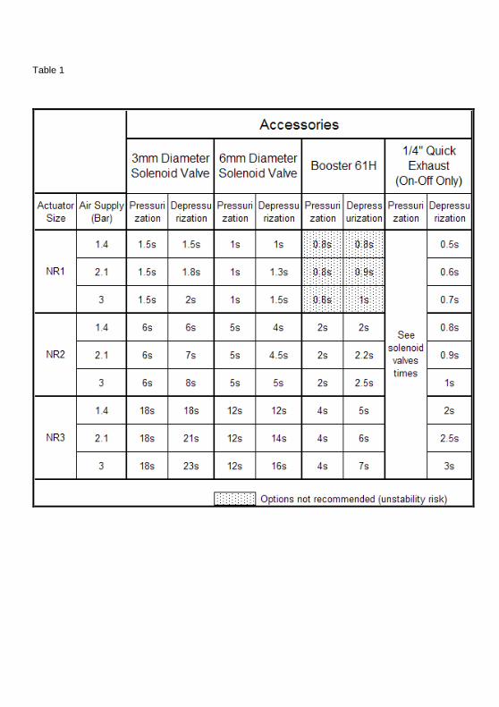
Table 1
4. Installation and Commissioning
4.1 Installation
The MaxFlo 3 valve must be installed per standard practices outlined in the Installation Manual.
The environment must be checked to verify that environmental conditions do not exceed the ratings.
The MaxFlo 3 must be accessible for physical inspection.
4.2 Physical Location and Placement
The MaxFlo 3 shall be accessible with sufficient room for pneumatic connections and shall allow manual proof testing.
Pneumatic piping to the valve shall be kept as short and straight as possible to minimize the airflow restrictions and potential clogging. Long or kinked pneumatic tubes may also increase the valve closure time.
The MaxFlo 3 shall be mounted in a low vibration environment. If excessive vibration can be expected special precautions shall be taken to ensure the integrity of pneumatic connectors or the vibration should be reduced using appropriate damping mounts.
4.3 Pneumatic Connections
Recommended piping for the inlet and outlet pneumatic connections to the MaxFlo 3 is 1/2” stainless steel or PVC tubing. The length of tubing between the MaxFlo 3 and the control device, such as a solenoid valve, shall be kept as short as possible and free of kinks.
Only dry instrument air filtered to 50 micron level or better shall be used.
The process air pressure shall meet the requirements set forth in the installation manual.
The process air capacity shall be sufficient to move the valve within the required time.
5. Operation and Maintenance
5.1 Proof test without automatic testing
The objective of proof testing is to detect failures within a Flowserve Solenoid that are not detected by any automatic diagnostics of the system. Of main concern are undetected failures that prevent the safety instrumented function from performing its intended function.
The frequency of proof testing, or the proof test interval, is to be determined in reliability calculations for the safety instrumented functions for which a Flowserve Solenoid is applied. The proof tests must be performed more frequently than or as frequently as specified in the calculation in order to maintain the required safety integrity of the safety instrumented function.
The following proof test is recommended. The results of the proof test should be recorded and any failures that are detected and that compromise functional safety should be reported to Flowserve Valves. The suggested proof test consists of a full stroke of the MaxFlo 3 valve.
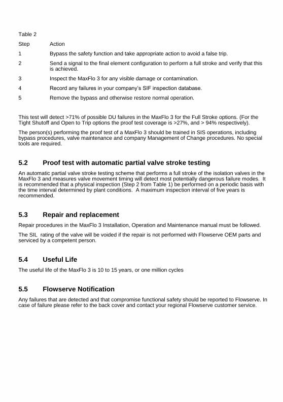
Table 2
Step Action
1 Bypass the safety function and take appropriate action to avoid a false trip.
2 Send a signal to the final element configuration to perform a full stroke and verify that this is achieved.
3 Inspect the MaxFlo 3 for any visible damage or contamination.
4 Record any failures in your company’s SIF inspection database.
5 Remove the bypass and otherwise restore normal operation.
This test will detect >71% of possible DU failures in the MaxFlo 3 for the Full Stroke options. (For the Tight Shutoff and Open to Trip options the proof test coverage is >27%, and > 94% respectively).
The person(s) performing the proof test of a MaxFlo 3 should be trained in SIS operations, including bypass procedures, valve maintenance and company Management of Change procedures. No special tools are required.
5.2 Proof test with automatic partial valve stroke testing
An automatic partial valve stroke testing scheme that performs a full stroke of the isolation valves in the MaxFlo 3 and measures valve movement timing will detect most potentially dangerous failure modes. It is recommended that a physical inspection (Step 2 from Table 1) be performed on a periodic basis with the time interval determined by plant conditions. A maximum inspection interval of five years is recommended.
5.3 Repair and replacement
Repair procedures in the MaxFlo 3 Installation, Operation and Maintenance manual must be followed.
The SIL rating of the valve will be voided if the repair is not performed with Flowserve OEM parts and serviced by a competent person.
5.4 Useful Life
The useful life of the MaxFlo 3 is 10 to 15 years, or one million cycles
5.5 Flowserve Notification
Any failures that are detected and that compromise functional safety should be reported to Flowserve. In case of failure please refer to the back cover and contact your regional Flowserve customer service.
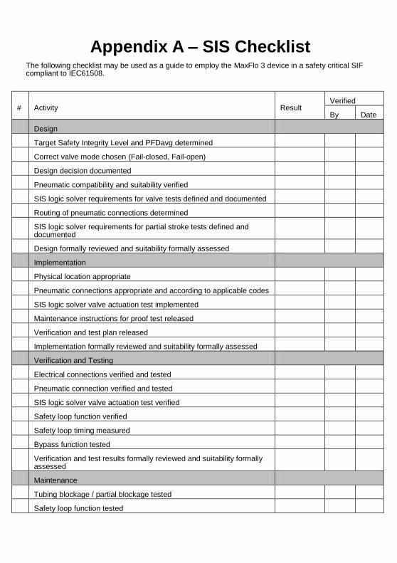
Appendix A – SIS Checklist The following checklist may be used as a guide to employ the MaxFlo 3 device in a safety critical SIF compliant to IEC61508.
# Activity Result Verified
By Date
Design
Target Safety Integrity Level and PFDavg determined
Correct valve mode chosen (Fail-closed, Fail-open)
Design decision documented
Pneumatic compatibility and suitability verified
SIS logic solver requirements for valve tests defined and documented
Routing of pneumatic connections determined
SIS logic solver requirements for partial stroke tests defined and documented
Design formally reviewed and suitability formally assessed
Implementation
Physical location appropriate
Pneumatic connections appropriate and according to applicable codes
SIS logic solver valve actuation test implemented
Maintenance instructions for proof test released
Verification and test plan released
Implementation formally reviewed and suitability formally assessed
Verification and Testing
Electrical connections verified and tested
Pneumatic connection verified and tested
SIS logic solver valve actuation test verified
Safety loop function verified
Safety loop timing measured
Bypass function tested
Verification and test results formally reviewed and suitability formally assessed
Maintenance
Tubing blockage / partial blockage tested
Safety loop function tested

NOTES