drives montado sempai nel
TRANSCRIPT
ABB industrial drivesACS800, single drives, 0.55 to 2800 kW
Technical catalogue
BUSINESSPROFILE INDUSTRIES
APPLICATIONS EXPERTISE
PARTNERS
PRODUCTS
SERVICES

2 3AFE 68375126 REV C EN 3.6.2005
Contents
12
3
4
56
Product series
Single drivesTypes and constructionsRatingsVoltages
Dimensions
Hardware options
Control connections and communications
Application software and programming
PC tools
Summary of features and options
Services and support
Contact and web information
Type code ACS800 - 01 - XXXX - X + XXXX1102071737
789

33AFE 68375126 REV C EN 3.6.2005
ABB industrial drives, single drives
ABB industrial drives ...................................................... 4Single drive main features .............................................. 6Technical specification ................................................... 8
Wall-mounted drive, ACS800-01 .................................... 9Wall-mounted regenerative drive, ACS800-11 .............. 12Free-standing drive, ACS800-02 .................................. 14Cabinet-built drive, ACS800-07 .................................... 16Cabinet-built regenerative drive, ACS800-17 ................ 20Cabinet-built low harmonic drive, ACS800-37 ............... 23
Brake options ............................................................. 26EMC filters .................................................................. 29Sine filters ................................................................... 30Sine filter drives ........................................................... 32du/dt filters .................................................................. 33
Standard user interfaceControl panel ......................................................... 35Standard I/O .......................................................... 36
OptionsOptional I/O ........................................................... 37Fieldbus control ...................................................... 38Remote monitoring and diagnostics tool .................. 39
Standard application software ...................................... 40Optional application software
Control solutions for different applications ................ 41
DriveSize .................................................................... 43DriveAP ...................................................................... 44DriveWindow 2 ............................................................ 45DriveWindow Light 2 ................................................... 46DriveOPC ................................................................... 47
Table .......................................................................... 48
Services and support ................................................... 50
www.abb.com/motors&drives ...................................... 51
12
3
4
56
789

4 3AFE 68375126 REV C EN 3.6.2005Product series
ABB industrial drives
ABB industrial drives
ABB industrial drives are designed for industrialapplications, and especially for applications in processindustries such as the pulp & paper, metals, mining,cement, power, chemical, and oil & gas industries.ABB industrial drives are highly flexible AC drives thatcan be configured to meet the precise needs of indus-trial applications, and hence order-based configurationis an integral part of the offering. These drives cover awide range of powers and voltages, including indus-trial voltages up to 690 V. ABB industrial drives comewith a wide range of inbuilt options. A key feature ofthese drives is programmability, which makes adapta-tion to different applications easy.
Industrial design
ABB industrial drives are designed with current ratingsto be used in industrial environment for applicationsrequiring high overloadability. The heart of the drive isDTC, Direct Torque Control, that provides high perfor-mance and significant benefits: e.g. accurate static anddynamic speed and torque control, high starting torqueand long motor cables. Inbuilt drive options make theinstallation work fast and easy. The robust enclosuresand cabinets, with a wide range of enclosure classes,as well as power terminals, are designed for harshenvironments.
One of the most significant design criteria of ABBindustrial drives has been the long lifetime. Wearingparts such as fans and capacitors have been selectedaccordingly. This means - together with extensiveprotection features - excellent reliability in the de-manding industrial market.
IndustrialIT enabled
ABB industrial drives are IndustrialIT enabled. Thisguarantees the user that ABB industrial drives can beeasily integrated into ABB Industrial IT systems.
Single drives
The single drive configuration contains a rectifier, DClink and an inverter in one single AC drive unit.
Other productsPlease also see the separate technical cataloguesACS800, multidrive, code 3AFE 68248531 EN andACS800, drive modules, code 3AFE 68404592 EN.
Single drive
Rectifier InverterDC link
The single drives are complete AC drives that can beinstalled without any additional cabinet or enclosure.The single drives are available as wall-mounted, free-standing and cabinet-built constructions. The protectionclass of the single drives is at least IP 21, and higherprotection classes are available as an option.
Type code
This is the unique reference number that clearlyidentifies your drive by construction, power ratingvoltage and selected options. By type code you canspecify your drives from the wide range of availableoptions, customer specific ones are added to the typecode using the corresponding + code.
ACS800 - 01 - XXXX - X + XXXX1102071737

53AFE 68375126 REV C EN 3.6.2005 Product series
Wall-mounted drive, ACS800-01
The wall-mounted drive, ACS800-01 offers all that youneed up to 110 kW. All important features and optionsare built inside the drive: line choke, EMC filter, brakechopper etc. The user gets everything in a single andcomplete IP 21 or IP 55 package. Still the drive is alsoextremely small. A wide range of software alternativesmakes this drive suitable for any application.
Wall-mounted regenerative drive,ACS800-11
The wall-mounted drive, ACS800-11 is equipped withactive supply unit. It offers a full performance regenera-tive drive in a single compact package. All importantfeatures and options including an LCL line filter andEMC filter are built inside the drive. The power ratingsstart from 7.5 kW and go up to 110 kW. It is availablewith IP 21 protection class.
Free-standing drive, ACS800-02
The free-standing drive, ACS800-02 is a new innova-tive bookshelf enclosure. The power ratings start from45 kW and go up to 560 kW. The ACS800-02 is avail-able in an extremely compact IP 21 enclosure anduniquely offers two mounting directions. It also offersa wide range of inbuilt options including, EMC filters,brake choppers, line apparatus such as fuse switchand contactor.
Cabinet-built drive, ACS800-07
The cabinet-built drive, ACS800-07 offers standardizedconfigurations that can be adapted to any applica-tion. It covers a wide power range up to 2800 kW andis very compact, the largest drive is only 3.2 meterswide. It is available with IP 21, IP 22, IP 42, IP 54 andIP 54R protection classes. A wide range of inbuiltoptions is available and application engineeringservices can be offered when customization is needed.
Cabinet-built regenerative drive, ACS800-17
The cabinet-built drive, ACS800-17 is equipped withactive supply unit. It is intended to drive applicationswhere regenerative operation is required. It covers awide power range and has an extensive range ofstandardised configurations that can be adapted toany application. It is available with IP 21, IP 22, IP 42,IP 54 and IP 54R protection classes.
Cabinet-built low harmonic drive,ACS800-37
The cabinet-built drive, ACS800-37 provides a uniquelow harmonic solution that is incorporated in thedrive. It has exceptionally low line harmonic contentand it fulfils even the strictest harmonic requirementswithout external filtering devices or multi-pulse trans-former arrangements. Like other cabinet-built stand-alone drives, it has a wide range of standardisedconfigurations and is available with IP 21, IP 22, IP 42,IP 54 and IP 54R protection classes.
6 3AFE 68375126 REV C EN 3.6.2005Product series
NotesFeatures Benefits
Less space and installation work required.
Low harmonics, meaning less interference and lessheating in cables and transformers.
Filter also protects the drive from line side transients.
Standard solutions available from ABB that meetsmost of the customer needs.
Always the optimal braking option available.
No need for external braking chopperthus reducing size and installation cost.
Easy and fast commissioning and operation.
Standard I/O covers most requirements.
Connectable to commonly usedfieldbuses.
Flexibility. Possible to replace relays or even PLC insome applications.
One product series suits everywhere, meaning lesstraining and spare parts and standardized interfaceto drives.
Suitable solutions available for differentenvironments.
Suitable for heavy industrial use.
Reliable.
Long motor cables can be used without extraoutput filters.
No need to install extra components such as inputchokes or EMC filter.
For the lowest harmonic level, ACS800-37 offersalmost a harmonic free solution.
Custom made solutions are available in theACS800-07/-17/-37.
Brake chopper inbuilt in all frame sizes(standard/optional).
Regenerative braking with ACS800-11 andACS800-17.
Clear, alphanumeric display with start-up assistantthat guides through the start-up procedure.
Easy to use PC tools available for commissioning,maintenance, monitoring and programming.
Extensive standard and optional I/O.
I/O fulfills PELV (EN 50178).
Two levels of programmability:1. Parameter programming (standard)2. Adaptive programming (free block programming)
- standard feature- more blocks available as options- all I/Os are programmable
IP 21 - IP 55.
Components dimensioned for heavy duty and longlifetime.
Advanced thermal model allows high overloadability.
Compact size, everythingintegrated
Inbuilt harmonic filter in allACS800 drives
Wide range of optionsavailable
Versatile braking options
User interface
User friendly customerinterface
Versatile connections andcommunications
Extensive programmability
Industrial design
Wide power and voltagerange
Wide range of robustenclosures available
Robust main circuit design
Compact and complete
Single drive main features
73AFE 68375126 REV C EN 3.6.2005 Product series
Single drive main features
NotesFeatures Benefits
Extensive protections
Galvanic isolation of I/O
All terminals designed forindustrial use
Worldwide approvals: CE, UL,cUL, CSA, C-Tick, GOST R
Right performance for everyapplication
DTC, accurate dynamic andstatic speed and torquecontrol
DTC - allows highoverloadability and giveshigh starting torque
DTC, fast control
DTC, flux optimization andsophisticated motor model
DTC, mechanics friendly
DTC, line supply control
Made in ABB
Global market leader inAC drives.Long experience.
World wide service andsupport network
Enhanced reliability, fewer process interruptions.
Possibility also to protect motors and process.
Safe and reliable operation without separateisolators and relays.
Sufficient size even for large aluminum cables.
No need for special tools in I/O cabling.
Safe products that can be used everywhere in theworld.
Excellent process control even without pulseencoder - improved product quality, productivity,reliability and lower investment cost.
Reliable, smooth start without overdimensioningthe drive.
No unnecessary trips and process interruptions.
Excellent motor and drive efficiency - cost savings.
Less stress for mechanics improves reliability.
High performance and robust control in activesupply unit.
Well proven, safe and reliable solutions.
Application know-how.
Professional support available around the world.
Several adjustable limits to protect other equipmentalso.
Isolated input signals and relay outputs as standard.
Fast reaction to load or voltage variations preventstripping.
Rides through power interruptions by using kineticenergy of the load.
Optimal flux in the motor reduces losses.
No shock torques.
No torque ripple - minimized risk for torsionalvibration.
Active oscillation damping.
Applies for ACS800-11 and ACS800-17.
Industrial design

8 3AFE 68375126 REV C EN 3.6.2005Product series
Technical specification
Voltage 3-phase output voltage 0...U2IN//U3IN//U5IN//U7IN
for > 500 V units please see “Filter selection table for ACS800”under the du/dt filters on page 33
Frequency 0...±300 Hz(0...±100 Hz for -07/-17/-37 with du/dt filters)
Field weakening point 8...300 Hz
Motor control ABB’s Direct Torque Control (DTC)
Torque control: Torque step rise time:Open loop <5 ms with nominal torqueClosed loop <5 ms with nominal torque
Non-linearity:Open loop ±4% with nominal torqueClosed loop ±1% with nominal torque
Speed control: Static accuracy:Open loop 10% of motor slipClosed loop 0.01% of nominal speed
Dynamic accuracy:Open loop 0.3...0.4% sec. with 100% torque stepClosed loop 0.1...0.2% sec. with 100% torque step
CELow Voltage Directive 73/23/EEC with amendment 93/68/EECMachinery Directive 98/37/ECEMC Directive 89/336/EEC with amendment 93/68/EECQuality assurance system ISO 9001 andEnvironmental system ISO 14001UL, cUL 508A or 508C and CSA C22.2 NO.14-95, C-Tick, GOST R
2nd environment, unrestricted distribution- standard in -07 (frame size nxR8i), -17 and -37 (frame sizes R7i-nxR8i), option in the others1st environment, restricted distribution as options up to 1000 A inputcurrent
Motor connection
Product compliance
EMC (according to EN 61800-3)
Mains connection
Voltage and 3-phase, U2IN = 208 to 240 V, ± 10%,power range except -07, -17, -37
3-phase, U3IN = 380 to 415 V, ± 10%3-phase, U5IN = 380 to 500 V, ± 10%3-phase, U7IN = 525 to 690 V, ± 10%(600 V UL, CSA)
Frequency 48 to 63 Hz
Power factor cosϕ1 = 0.98 (fundamental)cosϕ = 0.93...0.95 (total)
Power factor (ACS800-17/-37)cosϕ1 = 1 (fundamental)cosϕ = 0.99 (total)
Efficiency (at nominal power)ACS800-0x 98%ACS800-1X 97%
Environmental limitsAmbient temperatureTransport -40...+70°CStorage -40...+70°COperation -15...+50°C, no frost allowed
40...50°C at reduced output current(1% / 1°C)
Cooling method: Dry clean air
Altitude0...1000 m without derating1000...4000 m with derating ~ (1% / 100 m)
(690 V units 1000...2000 m with derating)
Relative humidity 5 to 95%, no condensation allowed
Protection classIP 21 standard for -01, -11, -02, -07, -17, -37IP 22 option for -07, -17, -37IP 42 option for -07, -17, -37IP 54 option for -07, -17, -37IP 54R option for -07, -17, -37IP 55 option for -01R = outlet air duct connection
Paint colour -07, -17, -37: RAL 7035-01, -11, -02: NCS 1502-Y(RAL 90021, PMS 420 C)
Contamination levels No conductive dust allowedStorage IEC60721-3-1, Class 1C2 (chemical gases),
Class 1S2 (solid particles)Transportation IEC60721-3-2, Class 2C2 (chemical gases),
Class 2S2 (solid particles)Operation IEC60721-3-3, Class 3C1/3C2* (chemical
gases), Class 3S2 (solid particles)
C = chemically active substancesS = mechanically active substances* coated circuit boards
Available options are shown in the Summary of features and optionstable. Please see pages 48-49.
ACS800 - 01 - XXXX - X + XXXX1102071737
93AFE 68375126 REV C EN 3.6.2005 Single drives
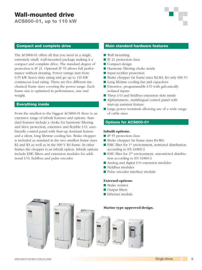
Main standard hardware features
■ Wall mounting■ IP 21 protection class■ Compact design■ Harmonic filtering choke inside■ Input rectifier protection■ Brake chopper (in frame sizes R2-R3; R4 only 690 V)■ Long lifetime cooling fan and capacitors■ Extensive, programmable I/O with galvanically
isolated inputs■ Three I/O and fieldbus extension slots inside■ Alphanumeric, multilingual control panel with
start-up assistant feature■ Large power terminals allowing use of a wide range
of cable sizes
Options for ACS800-01
Inbuilt options:■ IP 55 protection class■ Brake chopper (in frame sizes R4-R6)■ EMC filter for 1st environment, restricted distribution
according to EN 61800-3■ EMC filter for 2nd environment, unrestricted distribu-
tion according to EN 61800-3■ Analog and digital I/O extension modules■ Fieldbus modules■ Pulse encoder interface module
External options:■ Brake resistor■ Output filters■ Ethernet module
Marine type approved design.
Compact and complete drive
The ACS800-01 offers all that you need in a single,extremely small, wall-mounted package making it acompact and complete drive. The standard degree ofprotection is IP 21. Optional IP 55 allows full perfor-mance without derating. Power ratings start from0.55 kW heavy-duty rating and go up to 110 kWcontinuous load rating. There are five different me-chanical frame sizes covering the power range. Eachframe size is optimized in performance, size andweight.
Everything inside
From the smallest to the biggest ACS800-01 there is anextensive range of inbuilt features and options. Stan-dard features include a choke for harmonic filteringand drive protection, extensive and flexible I/O, user-friendly control panel with Start-up Assistant featureand a silent, long lifetime cooling fan. Brake chopperis included as standard in the two smallest frame sizesR2 and R3 as well as in the 690 V R4 frame. In otherframes the chopper is an inbuilt option. Inbuilt optionsinclude EMC filters and extension modules for addi-tional I/O, fieldbus and pulse encoder.
Wall-mounted driveACS800-01, up to 110 kW
10 3AFE 68375126 REV C EN 3.6.2005Single drives
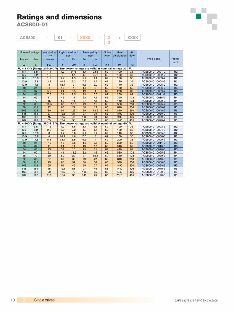
Ratings and dimensionsACS800-01
ACS800 - 01 - XXXX - 2 + XXXX3
Icont. max Imax Pcont. max IN PN Ihd Phd Type code Framesize
A A kW A kW A kW dBA W m3/hUN = 230 V (Range 208-240 V). The power ratings are valid at nominal voltage 230 V.
5.1 6.5 1.1 4.7 0.75 3.4 0.55 62 100 35 ACS800-01-0001-2 R26.5 8.2 1.5 6 1.1 4.3 0.75 62 100 35 ACS800-01-0002-2 R28.5 10.8 1.5 7.7 1.5 5.7 1.1 62 100 35 ACS800-01-0003-2 R2
10.9 13.8 2.2 10.2 2.2 7.5 1.5 62 120 35 ACS800-01-0004-2 R213.9 17.6 3 12.7 3 9.3 2.2 62 140 35 ACS800-01-0005-2 R219 24 4 18 4 14 3 62 160 69 ACS800-01-0006-2 R325 32 5.5 24 5.5 19 4 62 200 69 ACS800-01-0009-2 R334 46 7.5 31 7.5 23 5.5 62 250 69 ACS800-01-0011-2 R344 62 11 42 11 32 7.5 62 340 103 ACS800-01-0016-2 R455 72 15 50 11 37 7.5 62 440 103 ACS800-01-0020-2 R472 86 18.5 69 18.5 49 11 65 530 250 ACS800-01-0025-2 R586 112 22 80 22 60 15 65 610 250 ACS800-01-0030-2 R5
103 138 30 94 22 69 18.5 65 810 250 ACS800-01-0040-2 R5141 164 37 132 37 97 30 65 1190 405 ACS800-01-0050-2 R6166 202 45 155 45 115 30 65 1190 405 ACS800-01-0060-2 R6202 282 55 184 55 141 37 65 1440 405 ACS800-01-0070-2 R6
UN = 400 V (Range 380-415 V). The power ratings are valid at nominal voltage 400 V.5.1 6.5 1.5 4.7 1.5 3.4 1.1 62 100 35 ACS800-01-0003-3 R26.5 8.2 2.2 5.9 2.2 4.3 1.5 62 120 35 ACS800-01-0004-3 R28.5 10.8 3 7.7 3.0 5.7 2.2 62 140 35 ACS800-01-0005-3 R2
10.9 13.8 4 10.2 4.0 7.5 3 62 160 35 ACS800-01-0006-3 R213.9 17.6 5.5 12.7 5.5 9.3 4 62 200 35 ACS800-01-0009-3 R219 24 7.5 18 7.5 14 5.5 62 250 69 ACS800-01-0011-3 R325 32 11 24 11 19 7.5 62 340 69 ACS800-01-0016-3 R334 46 15 31 15 23 11 62 440 69 ACS800-01-0020-3 R344 62 22 41 18.5 32 15 62 530 103 ACS800-01-0025-3 R455 72 30 50 22 37 18.5 62 610 103 ACS800-01-0030-3 R472 86 37 69 30 49 22 65 810 250 ACS800-01-0040-3 R586 112 45 80 37 60 30 65 990 250 ACS800-01-0050-3 R5
103 138 55 94 45 69 37 65 1190 250 ACS800-01-0060-3 R5141 164 75 132 55 97 45 65 1440 405 ACS800-01-0070-3 R6166 202 90 155 75 115 55 65 1940 405 ACS800-01-0100-3 R6202 282 110 184 90 141 75 65 2310 405 ACS800-01-0120-3 R6
Nominal ratings No-overloaduse
Light-overloaduse
Heavy-dutyuse
Noiselevel
Heatdissipation
Airflow
113AFE 68375126 REV C EN 3.6.2005 Single drives
Icont. max Imax Pcont. max IN PN Ihd Phd Type code Framesize
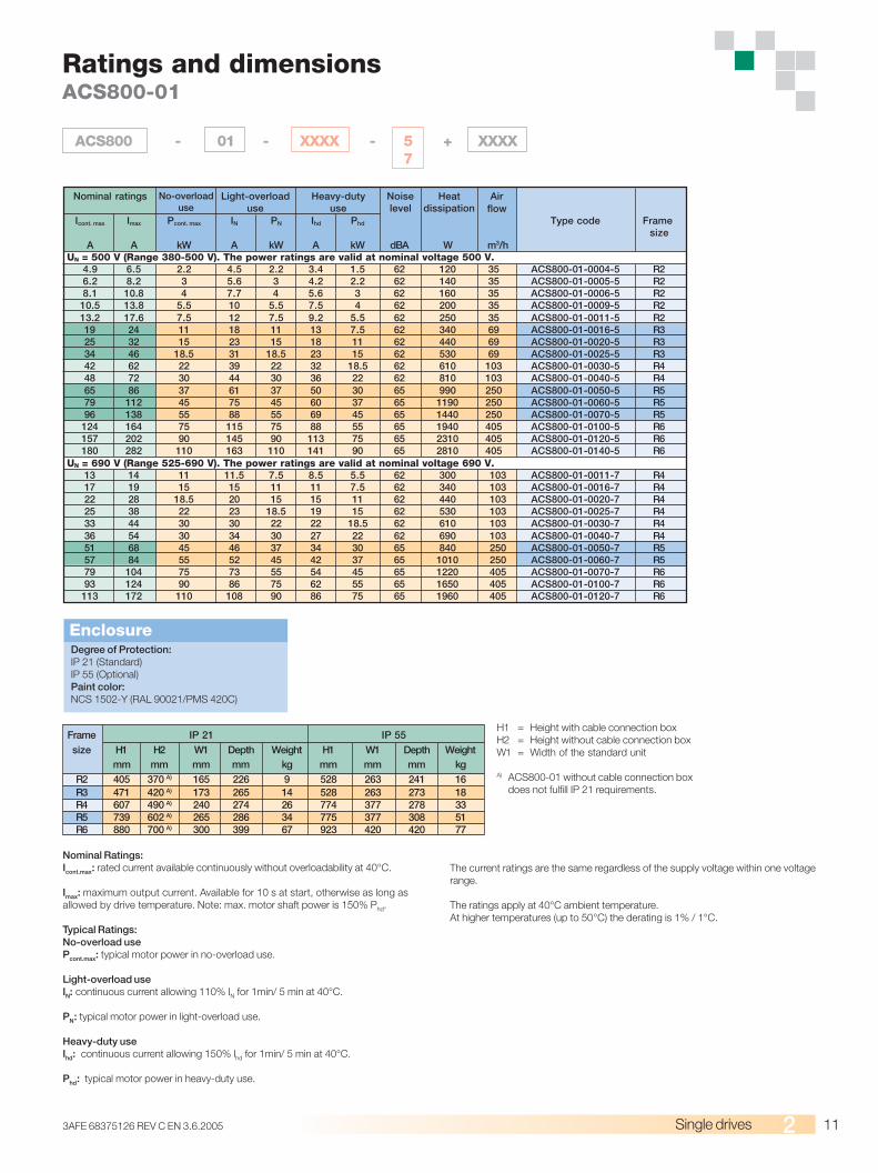
A A kW A kW A kW dBA W m3/hUN = 500 V (Range 380-500 V). The power ratings are valid at nominal voltage 500 V.
4.9 6.5 2.2 4.5 2.2 3.4 1.5 62 120 35 ACS800-01-0004-5 R26.2 8.2 3 5.6 3 4.2 2.2 62 140 35 ACS800-01-0005-5 R28.1 10.8 4 7.7 4 5.6 3 62 160 35 ACS800-01-0006-5 R2
10.5 13.8 5.5 10 5.5 7.5 4 62 200 35 ACS800-01-0009-5 R213.2 17.6 7.5 12 7.5 9.2 5.5 62 250 35 ACS800-01-0011-5 R219 24 11 18 11 13 7.5 62 340 69 ACS800-01-0016-5 R325 32 15 23 15 18 11 62 440 69 ACS800-01-0020-5 R334 46 18.5 31 18.5 23 15 62 530 69 ACS800-01-0025-5 R342 62 22 39 22 32 18.5 62 610 103 ACS800-01-0030-5 R448 72 30 44 30 36 22 62 810 103 ACS800-01-0040-5 R465 86 37 61 37 50 30 65 990 250 ACS800-01-0050-5 R579 112 45 75 45 60 37 65 1190 250 ACS800-01-0060-5 R596 138 55 88 55 69 45 65 1440 250 ACS800-01-0070-5 R5
124 164 75 115 75 88 55 65 1940 405 ACS800-01-0100-5 R6157 202 90 145 90 113 75 65 2310 405 ACS800-01-0120-5 R6180 282 110 163 110 141 90 65 2810 405 ACS800-01-0140-5 R6
UN = 690 V (Range 525-690 V). The power ratings are valid at nominal voltage 690 V.13 14 11 11.5 7.5 8.5 5.5 62 300 103 ACS800-01-0011-7 R417 19 15 15 11 11 7.5 62 340 103 ACS800-01-0016-7 R422 28 18.5 20 15 15 11 62 440 103 ACS800-01-0020-7 R425 38 22 23 18.5 19 15 62 530 103 ACS800-01-0025-7 R433 44 30 30 22 22 18.5 62 610 103 ACS800-01-0030-7 R436 54 30 34 30 27 22 62 690 103 ACS800-01-0040-7 R451 68 45 46 37 34 30 65 840 250 ACS800-01-0050-7 R557 84 55 52 45 42 37 65 1010 250 ACS800-01-0060-7 R579 104 75 73 55 54 45 65 1220 405 ACS800-01-0070-7 R693 124 90 86 75 62 55 65 1650 405 ACS800-01-0100-7 R6
113 172 110 108 90 86 75 65 1960 405 ACS800-01-0120-7 R6
Nominal ratings No-overloaduse
Light-overloaduse
Heavy-dutyuse
Noiselevel
Heatdissipation
Airflow
Ratings and dimensionsACS800-01
Degree of Protection:IP 21 (Standard)IP 55 (Optional)Paint color:NCS 1502-Y (RAL 90021/PMS 420C)
Enclosure
Frame IP 21 IP 55size H1 H2 W1 Depth Weight H1 W1 Depth Weight
mm mm mm mm kg mm mm mm kgR2 405 370 A) 165 226 9 528 263 241 16R3 471 420 A) 173 265 14 528 263 273 18R4 607 490 A) 240 274 26 774 377 278 33R5 739 602 A) 265 286 34 775 377 308 51R6 880 700 A) 300 399 67 923 420 420 77
Nominal Ratings:Icont.max: rated current available continuously without overloadability at 40°C.
Imax: maximum output current. Available for 10 s at start, otherwise as long asallowed by drive temperature. Note: max. motor shaft power is 150% Phd.
Typical Ratings:No-overload usePcont.max: typical motor power in no-overload use.
Light-overload useIN: continuous current allowing 110% IN for 1min/ 5 min at 40°C.
PN: typical motor power in light-overload use.
Heavy-duty useIhd: continuous current allowing 150% Ihd for 1min/ 5 min at 40°C.
Phd: typical motor power in heavy-duty use.
The current ratings are the same regardless of the supply voltage within one voltagerange.
The ratings apply at 40°C ambient temperature.At higher temperatures (up to 50°C) the derating is 1% / 1°C.
H1 = Height with cable connection boxH2 = Height without cable connection boxW1 = Width of the standard unit
A) ACS800-01 without cable connection boxdoes not fulfill IP 21 requirements.
ACS800 - 01 - XXXX - 5 + XXXX7
12 3AFE 68375126 REV C EN 3.6.2005Single drives
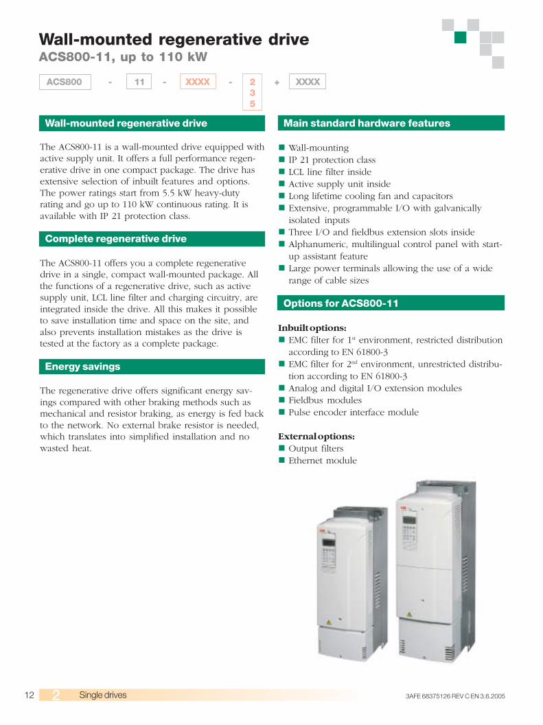
Wall-mounted regenerative drive
The ACS800-11 is a wall-mounted drive equipped withactive supply unit. It offers a full performance regen-erative drive in one compact package. The drive hasextensive selection of inbuilt features and options.The power ratings start from 5.5 kW heavy-dutyrating and go up to 110 kW continuous rating. It isavailable with IP 21 protection class.
Complete regenerative drive
The ACS800-11 offers you a complete regenerativedrive in a single, compact wall-mounted package. Allthe functions of a regenerative drive, such as activesupply unit, LCL line filter and charging circuitry, areintegrated inside the drive. All this makes it possibleto save installation time and space on the site, andalso prevents installation mistakes as the drive istested at the factory as a complete package.
Energy savings
The regenerative drive offers significant energy sav-ings compared with other braking methods such asmechanical and resistor braking, as energy is fed backto the network. No external brake resistor is needed,which translates into simplified installation and nowasted heat.
Main standard hardware features
Wall-mountingIP 21 protection classLCL line filter insideActive supply unit insideLong lifetime cooling fan and capacitorsExtensive, programmable I/O with galvanicallyisolated inputsThree I/O and fieldbus extension slots insideAlphanumeric, multilingual control panel with start-up assistant featureLarge power terminals allowing the use of a widerange of cable sizes
Options for ACS800-11
Inbuilt options:EMC filter for 1st environment, restricted distributionaccording to EN 61800-3EMC filter for 2nd environment, unrestricted distribu-tion according to EN 61800-3Analog and digital I/O extension modulesFieldbus modulesPulse encoder interface module
External options:Output filtersEthernet module
Wall-mounted regenerative driveACS800-11, up to 110 kW
ACS800 - 11 - XXXX - 2 + XXXX35
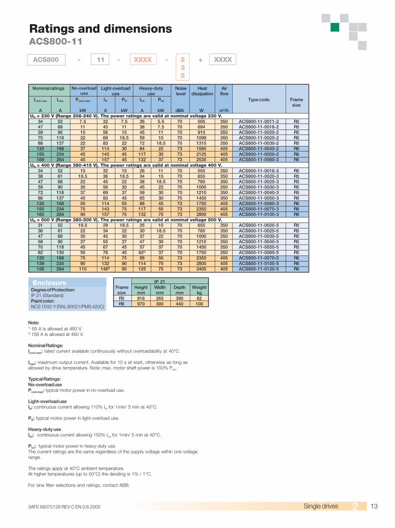
133AFE 68375126 REV C EN 3.6.2005 Single drives
Icont. max Imax Pcont. max IN PN Ihd Phd Type code Framesize
A A kW A kW A kW dBA W m3/hUN = 230 V (Range 208-240 V). The power ratings are valid at nominal voltage 230 V.
34 52 7.5 32 7.5 26 5.5 70 505 350 ACS800-11-0011-2 R547 68 11 45 11 38 7.5 70 694 350 ACS800-11-0016-2 R559 90 15 56 15 45 11 70 910 350 ACS800-11-0020-2 R575 118 22 69 18.5 59 15 70 1099 350 ACS800-11-0025-2 R588 137 22 83 22 72 18.5 70 1315 350 ACS800-11-0030-2 R5
120 168 37 114 30 84 22 73 1585 405 ACS800-11-0040-2 R6150 234 45 143 45 117 30 73 2125 405 ACS800-11-0050-2 R6169 264 45 157 45 132 37 73 2530 405 ACS800-11-0060-2 R6
UN = 400 V (Range 380-415 V). The power ratings are valid at nominal voltage 400 V.34 52 15 32 15 26 11 70 550 350 ACS800-11-0016-3 R538 61 18.5 36 18.5 34 15 70 655 350 ACS800-11-0020-3 R547 68 22 45 22 38 18.5 70 760 350 ACS800-11-0025-3 R559 90 30 56 30 45 22 70 1000 350 ACS800-11-0030-3 R572 118 37 69 37 59 30 70 1210 350 ACS800-11-0040-3 R586 137 45 83 45 65 30 70 1450 350 ACS800-11-0050-3 R5
120 168 55 114 55 88 45 73 1750 405 ACS800-11-0060-3 R6150 234 75 143 75 117 55 73 2350 405 ACS800-11-0070-3 R6165 264 90 157 75 132 75 73 2800 405 ACS800-11-0100-3 R6
UN = 500 V (Range 380-500 V). The power ratings are valid at nominal voltage 500 V.31 52 18.5 29 18.5 25 15 70 655 350 ACS800-11-0020-5 R536 61 22 34 22 30 18.5 70 760 350 ACS800-11-0025-5 R547 68 30 45 30 37 22 70 1000 350 ACS800-11-0030-5 R558 90 37 55 37 47 30 70 1210 350 ACS800-11-0040-5 R570 118 45 67 45 57 37 70 1450 350 ACS800-11-0050-5 R582 130 55 78 45 621) 37 70 1750 350 ACS800-11-0060-5 R5
120 168 75 114 75 88 55 73 2350 405 ACS800-11-0070-5 R6139 234 90 132 90 114 75 73 2800 405 ACS800-11-0100-5 R6156 264 110 1482) 90 125 75 73 3400 405 ACS800-11-0120-5 R6
EnclosureDegree of Protection:IP 21 (Standard)Paint color:NCS 1502-Y (RAL 90021/PMS 420C)
IP 21Frame Height Width Depth Weightsize mm mm mm kgR5 816 265 390 62R6 970 300 440 100
Note:1) 65 A is allowed at 460 V.2) 156 A is allowed at 460 V.
Nominal Ratings:Icont.max: rated current available continuously without overloadability at 40°C.
Imax: maximum output current. Available for 10 s at start, otherwise as long asallowed by drive temperature. Note: max. motor shaft power is 150% Phd.
Typical Ratings:No-overload usePcont.max: typical motor power in no-overload use.
Light-overload useIN: continuous current allowing 110% IN for 1min/ 5 min at 40°C.
PN: typical motor power in light-overload use.
Heavy-duty useIhd: continuous current allowing 150% Ihd for 1min/ 5 min at 40°C.
Phd: typical motor power in heavy-duty use.The current ratings are the same regardless of the supply voltage within one voltagerange.
The ratings apply at 40°C ambient temperature.At higher temperatures (up to 50°C) the derating is 1% / 1°C.
For sine filter selections and ratings, contact ABB.
Ratings and dimensionsACS800-11
ACS800 - 11 - XXXX - 2 + XXXX35
Nominal ratings No-overloaduse
Light-overloaduse
Heavy-dutyuse
Noiselevel
Heatdissipation
Airflow
14 3AFE 68375126 REV C EN 3.6.2005Single drives
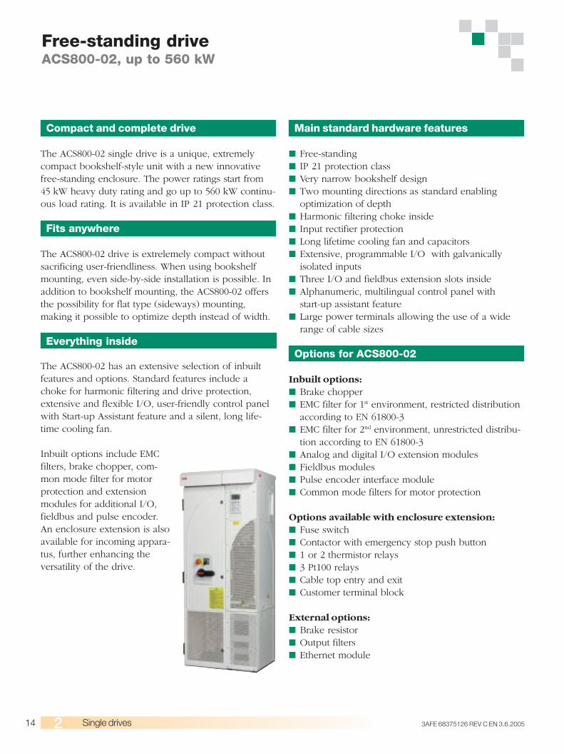
Compact and complete drive
The ACS800-02 single drive is a unique, extremelycompact bookshelf-style unit with a new innovativefree-standing enclosure. The power ratings start from45 kW heavy duty rating and go up to 560 kW continu-ous load rating. It is available in IP 21 protection class.
Fits anywhere
The ACS800-02 drive is extrelemely compact withoutsacrificing user-friendliness. When using bookshelfmounting, even side-by-side installation is possible. Inaddition to bookshelf mounting, the ACS800-02 offersthe possibility for flat type (sideways) mounting,making it possible to optimize depth instead of width.
Everything inside
The ACS800-02 has an extensive selection of inbuiltfeatures and options. Standard features include achoke for harmonic filtering and drive protection,extensive and flexible I/O, user-friendly control panelwith Start-up Assistant feature and a silent, long life-time cooling fan.
Inbuilt options include EMCfilters, brake chopper, com-mon mode filter for motorprotection and extensionmodules for additional I/O,fieldbus and pulse encoder.An enclosure extension is alsoavailable for incoming appara-tus, further enhancing theversatility of the drive.
Free-standing driveACS800-02, up to 560 kW
Main standard hardware features
■ Free-standing■ IP 21 protection class■ Very narrow bookshelf design■ Two mounting directions as standard enabling
optimization of depth■ Harmonic filtering choke inside■ Input rectifier protection■ Long lifetime cooling fan and capacitors■ Extensive, programmable I/O with galvanically
isolated inputs■ Three I/O and fieldbus extension slots inside■ Alphanumeric, multilingual control panel with
start-up assistant feature■ Large power terminals allowing the use of a wide
range of cable sizes
Options for ACS800-02
Inbuilt options:■ Brake chopper■ EMC filter for 1st environment, restricted distribution
according to EN 61800-3■ EMC filter for 2nd environment, unrestricted distribu-
tion according to EN 61800-3■ Analog and digital I/O extension modules■ Fieldbus modules■ Pulse encoder interface module■ Common mode filters for motor protection
Options available with enclosure extension:■ Fuse switch■ Contactor with emergency stop push button■ 1 or 2 thermistor relays■ 3 Pt100 relays■ Cable top entry and exit■ Customer terminal block
External options:■ Brake resistor■ Output filters■ Ethernet module

153AFE 68375126 REV C EN 3.6.2005 Single drives
Degree of Protection:IP 21 (Standard)Paint color:NCS 1502-Y (RAL 90021/PMS 420C)
EnclosureHeight Width 1 Width 2 Depth Weight Weight withmm mm mm mm kg enclosure
extension *) kg
R7 1507 250 A) 602 524 A) B) 110 234R8 2024 347 A) 793 622 A) B) 240 450
Icont. max Imax Pcont. max IN PN Ihd Phd Type code Framesize
A A kW A kW A kW dBA W m3/h UN = 230 V (Ranges 208-240 V). The power ratings are valid at nominal voltage 230 V.
214 326 55 211 55 170 45 71 2900 540 ACS800-02-0080-2 R7253 404 75 248 75 202 55 71 3450 540 ACS800-02-0100-2 R7295 432 90 290 90 240 1) 55 71 4050 540 ACS800-02-0120-2 R7405 588 110 396 110 316 90 72 5300 1220 ACS800-02-0140-2 R8447 588 132 440 132 340 90 72 6100 1220 ACS800-02-0170-2 R8528 588 160 516 160 370 110 72 6700 1220 ACS800-02-0210-2 R8613 840 160 598 160 480 132 72 7600 1220 ACS800-02-0230-2 R8693 1017 200 679 200 590 2) 160 72 7850 1220 ACS800-02-0260-2 R8720 1017 200 704 200 635 3) 200 72 8300 1220 ACS800-02-0300-2 R8
UN = 400 V (Ranges 380-415 V). The power ratings are valid at nominal voltage 400 V.206 326 110 202 110 163 90 71 3000 540 ACS800-02-0140-3 R7248 404 132 243 132 202 110 71 3650 540 ACS800-02-0170-3 R7289 432 160 284 160 240 4) 132 71 4300 540 ACS800-02-0210-3 R7445 588 200 440 200 340 160 72 6600 1220 ACS800-02-0260-3 R8521 588 250 516 250 370 200 72 7150 1220 ACS800-02-0320-3 R8602 840 315 590 315 477 250 72 8100 1220 ACS800-02-0400-3 R8693 1017 355 679 355 590 2) 315 72 8650 1220 ACS800-02-0440-3 R8720 1017 400 704 400 635 3) 355 72 9100 1220 ACS800-02-0490-3 R8
UN = 500 V (Ranges 380-500 V). The power ratings are valid at nominal voltage 500 V.196 326 132 192 132 162 110 71 3000 540 ACS800-02-0170-5 R7245 384 160 240 160 192 132 71 3800 540 ACS800-02-0210-5 R7289 432 200 284 200 224 160 71 4500 540 ACS800-02-0260-5 R7440 588 250 435 250 340 200 72 6850 1220 ACS800-02-0320-5 R8515 588 315 510 315 370 250 72 7800 1220 ACS800-02-0400-5 R8550 840 355 545 355 490 315 72 7600 1220 ACS800-02-0440-5 R8602 840 400 590 400 515 2) 355 72 8100 1220 ACS800-02-0490-5 R8684 1017 450 670 450 590 2) 400 72 9100 1220 ACS800-02-0550-5 R8718 1017 500 704 500 632 3) 450 72 9700 1220 ACS800-02-0610-5 R8
UN = 690 V (Ranges 525-690 V). The power ratings are valid at nominal voltage 690 V.134 190 132 125 110 95 90 71 2800 540 ACS800-02-0140-7 R7166 263 160 155 132 131 110 71 3550 540 ACS800-02-0170-7 R7
166/2035) 294 160 165/1955) 160 147 132 71 4250 540 ACS800-02-0210-7 R7175/2305) 326 160/2005) 175/2125) 160/2005) 163 160 71 4800 540 ACS800-02-0260-7 R7
315 433 315 290 250 216 200 72 6150 1220 ACS800-02-0320-7 R8353 548 355 344 315 274 250 72 6650 1220 ACS800-02-0400-7 R8396 656 400 387 355 328 315 72 7400 1220 ACS800-02-0440-7 R8445 775 450 426 400 387 355 72 8450 1220 ACS800-02-0490-7 R8488 853 500 482 450 426 400 72 8300 1220 ACS800-02-0550-7 R8560 964 560 537 500 482 450 72 9750 1220 ACS800-02-0610-7 R8
Nominal ratings No-overloaduse
Light-overloaduse
Heavy-dutyuse
Noiselevel
Heatdissipation
Airflow
Width 1 = Width of the standard unitWidth 2 = Width with the enclosure extension
A) The dimensions apply to bookshelf mounting. In flat type mounting the widthand depth change places.
B) With enclosure extension the depth is increased by 25 mm due to the switchfuse handle.
*) Weights are for the basic configuration with switch fuse, but without contactorand other options.
Nominal Ratings:Icont.max: rated current available continuously without overloadability at 40°C.
Imax: maximum output current. Available for 10 s at start, otherwise as long asallowed by drive temperature. Note: max. motor shaft power is 150% Phd.
Typical Ratings:No-overload usePcont.max: typical motor power in no-overload use.
Ratings and dimensionsACS800-02
IP 21
ACS800 - 02 - XXXX - 2 + XXXX357
Light-overload useIN: continuous current allowing 110% IN for 1 min / 5 min at 40°C.
PN: typical motor power in light-overload use.
Heavy-duty useIhd: continuous current allowing 150% Ihd for 1 min / 5 min at 40°C.
Phd: typical motor power in heavy-duty use.
The current ratings are the same regardless of the supply voltage within onevoltage range.
The ratings apply at 40°C ambient temperature.At higher temperatures (up to 50°C) the derating is 1% / 1°C.
Notes:1) 50% overload available if Tamb < 35°C. If Tamb = 40°C, max overload is 45%.2) 50% overload available if Tamb < 30°C. If Tamb = 40°C, max overload is 40%.3) 50% overload available if Tamb < 20°C. If Tamb = 40°C, max overload is 30%.4) 50% overload available if Tamb < 25°C. If Tamb = 40°C, max overload is 37%.5) Higher value available if output frequency is above 41 Hz.
Framesize

16 3AFE 68375126 REV C EN 3.6.2005Single drives
Customized solutions
The ACS800-07 is built in a robust cabinet designed forheavy industrial applications.
The ACS800-07 offers a wide variety of standardizedconfigurations to adapt to different application require-ments, from line contactor to prevention of unexpectedmotor start, or ATEX-approved motor protections.
If your application requires more, ABB’s applicationengineering services can add special features to thestandard product such as an additional cabinet forcustomer specific devices to ensure exact suitabilityfor the application.
Smart module concept
The drives up to 560 kW are based on a compactsingle module including rectifier and inverter.Larger drives consist of separate rectifier and invertermodules, which have plug-in power connectorsproviding easy maintenance and redundancy withparallel connected units. If one module becomesdefective, the drive can continue running with reducedpower after disconnecting the faulty module.The rectifier module of the larger drives provides 6- or12-pulse operation.
Extensive range of features
The ACS800-07 has an extensive range of inbuiltfeatures and options. Typical option choices includeextended I/O and fieldbus options, line contactor, EMCfiltering, common mode filtering and du/dt (voltagerise) filtering, all mountable within the single cabinet.
Main standard features
■ Compact design■ IP 21 protection class■ Inbuilt harmonic filtering choke■ Du/dt filters (in frame sizes nxR8i)
Cabinet-built driveACS800-07, up to 2800 kW
■ Common mode filters for motor protection(in frame sizes R8i)
■ Fuse switch (in frame sizes R6-R8)■ Main switch (in frame sizes nxR8i)■ Extensive, programmable I/O■ Inputs galvanically isolated■ 6- or 12-pulse operation (in frame sizes nxR8i)■ Long lifetime cooling fan and capacitors■ I/O and fieldbus extension slots inside■ Alphanumeric multilingual control panel with
start-up assistant feature■ EMC filter for 2nd environment, unrestricted distribu-
tion according to EN 61800-3 (in frame sizes nxR8i)
Options for ACS800-07
■ Analog and digital I/O extension modules■ ATEX approved motor protection■ Brake chopper and resistor■ Cabinet heater■ Common mode filters for motor protection
(in frame sizes R7-R8)■ Customer terminal block■ Du/dt filters (in frame sizes R6-R8)■ Earth fault monitoring for unearthed network■ EMC filter for 1st environment, restricted distribution
according to EN 61800-3■ EMC filter for 2nd environment, unrestricted distribu-
tion according to EN 61800-3 (in frame sizes R6-R8)■ Fieldbus modules■ IP 22, IP 42, IP 54 or IP 54R enclosure classes■ Line contactor with emergency stop push button■ Line fuses and load switch (in frame size nxR8i)■ Marine construction■ Output for fan motor■ Pulse encoder interface module■ Prevention of unexpected start up of motor■ Top entry and exit of cables■ 1 or 2 thermistor relays■ 3, 5 or 8 Pt100 relays
Plus tailor made options through ABB's applicationengineering.
173AFE 68375126 REV C EN 3.6.2005 Single drives
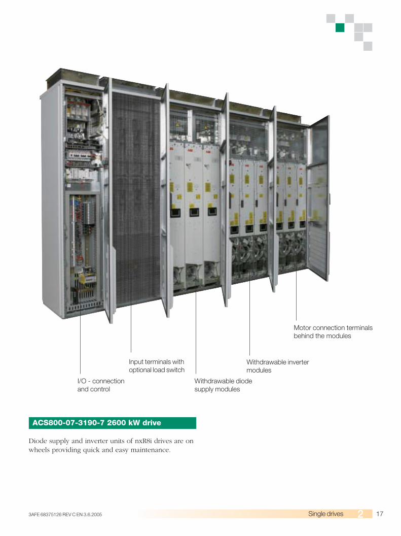
ACS800-07-3190-7 2600 kW drive
Diode supply and inverter units of nxR8i drives are onwheels providing quick and easy maintenance.
Motor connection terminalsbehind the modules
Withdrawable invertermodules
Withdrawable diodesupply modules
Input terminals withoptional load switch
I/O - connectionand control
18 3AFE 68375126 REV C EN 3.6.2005Single drives
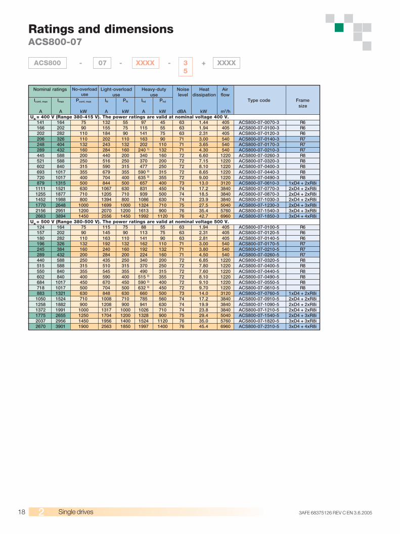
Ratings and dimensionsACS800-07
ACS800 - 07 - XXXX - 3 + XXXX5
Icont. max Imax Pcont. max IN PN Ihd Phd Type code Framesize
A A kW A kW A kW dBA kW m3/hUN = 400 V (Range 380-415 V). The power ratings are valid at nominal voltage 400 V.
141 164 75 132 55 97 45 63 1.44 405 ACS800-07-0070-3 R6166 202 90 155 75 115 55 63 1.94 405 ACS800-07-0100-3 R6202 282 110 184 90 141 75 63 2.31 405 ACS800-07-0120-3 R6206 326 110 202 110 163 90 71 3.00 540 ACS800-07-0140-3 R7248 404 132 243 132 202 110 71 3.65 540 ACS800-07-0170-3 R7289 432 160 284 160 240 1) 132 71 4.30 540 ACS800-07-0210-3 R7445 588 200 440 200 340 160 72 6.60 1220 ACS800-07-0260-3 R8521 588 250 516 250 370 200 72 7.15 1220 ACS800-07-0320-3 R8602 840 315 590 315 477 250 72 8.10 1220 ACS800-07-0400-3 R8693 1017 355 679 355 590 2) 315 72 8.65 1220 ACS800-07-0440-3 R8720 1017 400 704 400 635 3) 355 72 9.00 1220 ACS800-07-0490-3 R8879 1315 500 844 500 657 400 73 13.0 3120 ACS800-07-0610-3 1xD4 + 2xR8i
1111 1521 630 1067 630 831 450 74 17.2 3840 ACS800-07-0770-3 2xD4 + 2xR8i1255 1877 710 1205 710 939 500 74 18.5 3840 ACS800-07-0870-3 2xD4 + 2xR8i1452 1988 800 1394 800 1086 630 74 23.9 3840 ACS800-07-1030-3 2xD4 + 2xR8i1770 2648 1000 1699 1000 1324 710 75 27.5 5040 ACS800-07-1230-3 2xD4 + 3xR8i2156 2951 1200 2070 1200 1613 900 76 35.4 5760 ACS800-07-1540-3 3xD4 + 3xR8i2663 3894 1450 2556 1450 1992 1120 76 42.7 6960 ACS800-07-1850-3 3xD4 + 4xR8i
UN
= 500 V (Range 380-500 V). The power ratings are valid at nominal voltage 500 V.124 164 75 115 75 88 55 63 1.94 405 ACS800-07-0100-5 R6157 202 90 145 90 113 75 63 2.31 405 ACS800-07-0120-5 R6180 282 110 163 110 141 90 63 2.81 405 ACS800-07-0140-5 R6196 326 132 192 132 162 110 71 3.00 540 ACS800-07-0170-5 R7245 384 160 240 160 192 132 71 3.80 540 ACS800-07-0210-5 R7289 432 200 284 200 224 160 71 4.50 540 ACS800-07-0260-5 R7440 588 250 435 250 340 200 72 6.85 1220 ACS800-07-0320-5 R8515 588 315 510 315 370 250 72 7.80 1220 ACS800-07-0400-5 R8550 840 355 545 355 490 315 72 7.60 1220 ACS800-07-0440-5 R8602 840 400 590 400 515 2) 355 72 8.10 1220 ACS800-07-0490-5 R8684 1017 450 670 450 590 2) 400 72 9.10 1220 ACS800-07-0550-5 R8718 1017 500 704 500 632 3) 450 72 9.70 1220 ACS800-07-0610-5 R8883 1321 630 848 630 660 500 73 14.0 3120 ACS800-07-0760-5 1xD4 + 2xR8i
1050 1524 710 1008 710 785 560 74 17.2 3840 ACS800-07-0910-5 2xD4 + 2xR8i1258 1882 900 1208 900 941 630 74 19.9 3840 ACS800-07-1090-5 2xD4 + 2xR8i1372 1991 1000 1317 1000 1026 710 74 23.8 3840 ACS800-07-1210-5 2xD4 + 2xR8i1775 2655 1250 1704 1200 1328 900 75 29.4 5040 ACS800-07-1540-5 2xD4 + 3xR8i2037 2956 1450 1956 1400 1524 1120 76 35.0 5760 ACS800-07-1820-5 3xD4 + 3xR8i2670 3901 1900 2563 1850 1997 1400 76 45.4 6960 ACS800-07-2310-5 3xD4 + 4xR8i
Nominal ratings No-overloaduse
Light-overloaduse
Heavy-dutyuse
Noiselevel
Heatdissipation
Airflow
193AFE 68375126 REV C EN 3.6.2005 Single drives
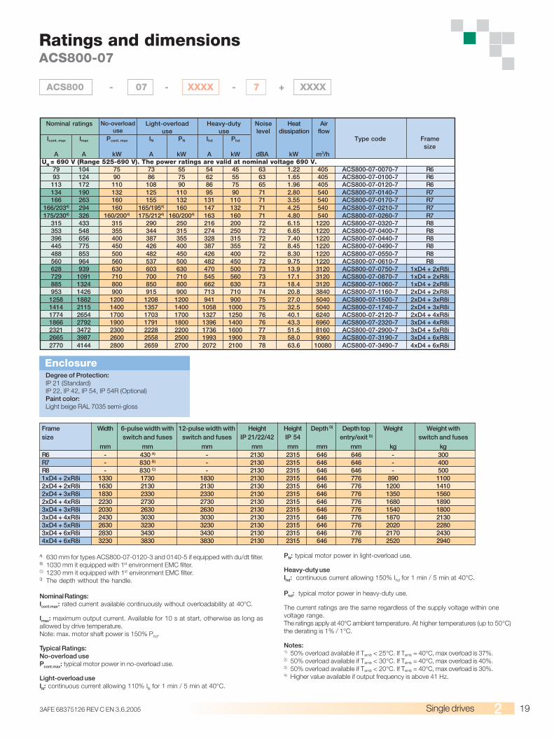
ACS800 - 07 - XXXX - 7 + XXXX
Ratings and dimensionsACS800-07
Icont. max Imax Pcont. max IN PN Ihd Phd Type code Framesize
A A kW A kW A kW dBA kW m3/hUN = 690 V (Range 525-690 V). The power ratings are valid at nominal voltage 690 V.
79 104 75 73 55 54 45 63 1.22 405 ACS800-07-0070-7 R693 124 90 86 75 62 55 63 1.65 405 ACS800-07-0100-7 R6
113 172 110 108 90 86 75 65 1.96 405 ACS800-07-0120-7 R6134 190 132 125 110 95 90 71 2.80 540 ACS800-07-0140-7 R7166 263 160 155 132 131 110 71 3.55 540 ACS800-07-0170-7 R7
166/2034) 294 160 165/1954) 160 147 132 71 4.25 540 ACS800-07-0210-7 R7175/2304) 326 160/2004) 175/2124) 160/2004) 163 160 71 4.80 540 ACS800-07-0260-7 R7
315 433 315 290 250 216 200 72 6.15 1220 ACS800-07-0320-7 R8353 548 355 344 315 274 250 72 6.65 1220 ACS800-07-0400-7 R8396 656 400 387 355 328 315 72 7.40 1220 ACS800-07-0440-7 R8445 775 450 426 400 387 355 72 8.45 1220 ACS800-07-0490-7 R8488 853 500 482 450 426 400 72 8.30 1220 ACS800-07-0550-7 R8560 964 560 537 500 482 450 72 9.75 1220 ACS800-07-0610-7 R8628 939 630 603 630 470 500 73 13.9 3120 ACS800-07-0750-7 1xD4 + 2xR8i729 1091 710 700 710 545 560 73 17.1 3120 ACS800-07-0870-7 1xD4 + 2xR8i885 1324 800 850 800 662 630 73 18.4 3120 ACS800-07-1060-7 1xD4 + 2xR8i953 1426 900 915 900 713 710 74 20.8 3840 ACS800-07-1160-7 2xD4 + 2xR8i
1258 1882 1200 1208 1200 941 900 75 27.0 5040 ACS800-07-1500-7 2xD4 + 3xR8i1414 2115 1400 1357 1400 1058 1000 75 32.5 5040 ACS800-07-1740-7 2xD4 + 3xR8i1774 2654 1700 1703 1700 1327 1250 76 40.1 6240 ACS800-07-2120-7 2xD4 + 4xR8i1866 2792 1900 1791 1800 1396 1400 76 43.3 6960 ACS800-07-2320-7 3xD4 + 4xR8i2321 3472 2300 2228 2200 1736 1600 77 51.5 8160 ACS800-07-2900-7 3xD4 + 5xR8i2665 3987 2600 2558 2500 1993 1900 78 58.0 9360 ACS800-07-3190-7 3xD4 + 6xR8i2770 4144 2800 2659 2700 2072 2100 78 63.6 10080 ACS800-07-3490-7 4xD4 + 6xR8i
Nominal ratings No-overloaduse
Light-overloaduse
Heavy-dutyuse
Noiselevel
Heatdissipation
Airflow
Frame Width 6-pulse width with 12-pulse width with Height Height Depth D) Depth top Weight Weight withsize switch and fuses switch and fuses IP 21/22/42 IP 54 entry/exit D) switch and fuses
mm mm mm mm mm mm mm kg kgR6 - 430 A) - 2130 2315 646 646 - 300R7 - 830 B) - 2130 2315 646 646 - 400R8 - 830 C) - 2130 2315 646 646 - 5001xD4 + 2xR8i 1330 1730 1830 2130 2315 646 776 890 11002xD4 + 2xR8i 1630 2130 2130 2130 2315 646 776 1200 14102xD4 + 3xR8i 1830 2330 2330 2130 2315 646 776 1350 15602xD4 + 4xR8i 2230 2730 2730 2130 2315 646 776 1680 18903xD4 + 3xR8i 2030 2630 2630 2130 2315 646 776 1540 18003xD4 + 4xR8i 2430 3030 3030 2130 2315 646 776 1870 21303xD4 + 5xR8i 2630 3230 3230 2130 2315 646 776 2020 22803xD4 + 6xR8i 2830 3430 3430 2130 2315 646 776 2170 24304xD4 + 6xR8i 3230 3830 3830 2130 2315 646 776 2520 2940
A) 630 mm for types ACS800-07-0120-3 and 0140-5 if equipped with du/dt filter.B) 1030 mm it equipped with 1st environment EMC filter.C) 1230 mm it equipped with 1st environment EMC filter.D) The depth without the handle.
Nominal Ratings:Icont.max: rated current available continuously without overloadability at 40°C.
Imax: maximum output current. Available for 10 s at start, otherwise as long asallowed by drive temperature.Note: max. motor shaft power is 150% Phd.
Typical Ratings:No-overload usePcont.max: typical motor power in no-overload use.
Light-overload useIN: continuous current allowing 110% IN for 1 min / 5 min at 40°C.
PN: typical motor power in light-overload use.
Heavy-duty useIhd: continuous current allowing 150% Ihd for 1 min / 5 min at 40°C.
Phd: typical motor power in heavy-duty use.
The current ratings are the same regardless of the supply voltage within onevoltage range.The ratings apply at 40°C ambient temperature. At higher temperatures (up to 50°C)the derating is 1% / 1°C.
Notes:1) 50% overload available if Tamb < 25°C. If Tamb = 40°C, max overload is 37%.2) 50% overload available if Tamb < 30°C. If Tamb = 40°C, max overload is 40%.3) 50% overload available if Tamb < 20°C. If Tamb = 40°C, max overload is 30%.4) Higher value available if output frequency is above 41 Hz.
Degree of Protection:IP 21 (Standard)IP 22, IP 42, IP 54, IP 54R (Optional)Paint color:Light beige RAL 7035 semi-gloss
Enclosure

20 3AFE 68375126 REV C EN 3.6.2005Single drives
Cabinet-built regenerative driveACS800-17, up to 2500 kW
Complete regenerative drive
The ACS800-17 offers you a complete regenerativedrive in a single, compact cabinet-built package. Thedrive includes everything that is needed for regenera-tive operation, including line filter. The active supplyunit allows full power flow both in motoring andgenerating modes.
Energy savings
Compared with other braking methods such as me-chanical and resistor braking, the energy savings canbe significant with the ACS800-17. The braking energyis returned to network, not wasted as heat. Handlingof waste heat may also be a problem if braking poweris significant. As no external braking devices areneeded with the ACS800-17, installation work is simplerand the space requirement for installation is less.
High performance
The ACS800-17 is especially suitable for demandingapplications. Transition between motoring and gener-ating is fast due to the patented DTC control method.The active supply unit is able to boost output voltage,which guarantees full motor voltage even when thesupply voltage is below nominal.
The active supply unit combined with the DTC controlcan even compensate for fast variations in line voltage.There is no risk of fuse blow or component damagedue to voltage drops in the network.
Extensive range of features
Adaptation to different application requirements ispossible by selecting from a wide range of standardizedconfigurations. The cabinet-built drive series enableshaving a significant amount of features and accessoriesas inbuilt options.
Main standard features
■ Compact design■ IP 21 protection class■ LCL line filter inside■ EMC filter for 2nd environment, unrestricted distribu-
tion according to EN 61800-3 (option in frame size R6)■ Main switch with aR fuses (in frame sizes R6-R8i)■ Line contactor (in frame sizes R7i-R8i, option in
frame size R6)■ Withdrawable air circuit breaker (in frame size
nxR8i)■ Du/dt filters (in frame size nxR8i)■ Coated boards■ Extensive, programmable I/O■ Long lifetime cooling fan and capacitors■ Inputs galvanically isolated■ I/O and fieldbus extension slots inside■ Alphanumeric multilingual control panel with start-up
assistant feature
Accessories for the ACS800-17
■ Analogue and digital I/O extension modules■ ATEX approved motor protection■ Cabinet heater■ Customer terminal block■ Du/dt filters (in frame sizes R6-R8i)■ Earth fault monitoring for unearthed network■ EMC filter for 1st environment, restricted distribution
according to EN 61800-3■ Fieldbus modules■ IP 22, IP 42, IP 54 or IP 54R enclosure classes■ Emergency stop, category 0 or 1■ Marine construction■ Output for motor fan■ Pulse encoder interface module■ Prevention of unexpected start up of motor■ Top entry and exit of cables■ 1 or 2 thermistor relays■ 3, 5 or 8 Pt100 relays
Plus tailor made accessories through ABB's applicationengineering.
213AFE 68375126 REV C EN 3.6.2005 Single drives
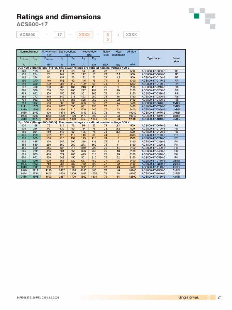
Ratings and dimensionsACS800-17
ACS800 - 17 - XXXX - 3 + XXXX5
Icont. max Imax Pcont. max IN PN Ihd Phd Type code Framesize
A A kW A kW A kW dBA kW m3/hUN = 400 V (Range 380-415 V). The power ratings are valid at nominal voltage 400 V.
120 168 55 114 55 84 45 73 1.8 500 ACS800-17-0060-3 R6150 234 75 142 75 117 55 73 2.4 500 ACS800-17-0070-3 R6165 264 90 157 75 132 75 73 2.8 500 ACS800-17-0100-3 R6195 270 110 183 90 146 75 74 6 1300 ACS800-17-0140-3 R7i240 330 132 226 110 180 90 74 7 1300 ACS800-17-0170-3 R7i292 400 160 280 160 218 110 75 8 3160 ACS800-17-0210-3 R8i370 506 200 355 200 277 132 75 10 3160 ACS800-17-0260-3 R8i469 642 250 450 250 351 200 75 13 3160 ACS800-17-0320-3 R8i565 773 315 542 315 423 250 75 16 3160 ACS800-17-0390-3 R8i704 963 400 675 355 526 250 75 22 3160 ACS800-17-0490-3 R8i919 1258 500 882 500 688 355 77 24 6400 ACS800-17-0640-3 2xR8i1111 1521 630 1067 630 831 450 77 31 6400 ACS800-17-0770-3 2xR8i1379 1888 800 1324 710 1031 560 77 43 6400 ACS800-17-0960-3 2xR8i1535 2102 900 1474 800 1149 630 78 46 10240 ACS800-17-1070-3 3xR8i1978 2707 1200 1899 1100 1479 800 78 63 10240 ACS800-17-1370-3 3xR8i2610 3573 1600 2506 1400 1953 1100 79 83 12800 ACS800-17-1810-3 4xR8i
UN = 500 V (Range 380-500 V). The power ratings are valid at nominal voltage 500 V.120 168 75 114 75 96 55 73 2.4 500 ACS800-17-0070-5 R6139 234 90 132 90 114 75 73 2.8 500 ACS800-17-0100-5 R6156 264 110 148 90 125 75 73 3.4 500 ACS800-17-0120-5 R6186 269 132 175 110 140 90 74 6 1300 ACS800-17-0170-5 R7i230 333 160 216 132 173 110 74 8 1300 ACS800-17-0210-5 R7i302 438 200 289 200 226 132 75 9 3160 ACS800-17-0260-5 R8i365 530 250 350 250 273 160 75 11 3160 ACS800-17-0320-5 R8i455 660 315 437 315 340 200 75 14 3160 ACS800-17-0400-5 R8i525 762 355 504 355 393 250 75 16 3160 ACS800-17-0460-5 R8i595 863 400 571 400 445 315 75 18 3160 ACS800-17-0510-5 R8i670 972 500 643 450 501 315 75 22 3160 ACS800-17-0580-5 R8i892 1294 630 856 630 667 450 77 26 6400 ACS800-17-0780-5 2xR8i1005 1458 710 965 630 752 500 77 32 6400 ACS800-17-0870-5 2xR8i1313 1906 900 1261 900 982 710 77 43 6400 ACS800-17-1140-5 2xR8i1528 2217 1120 1467 1120 1143 800 78 46 10240 ACS800-17-1330-5 3xR8i1884 2734 1400 1809 1300 1409 1000 78 64 10240 ACS800-17-1640-5 3xR8i2486 3608 1800 2387 1700 1860 1300 79 84 12800 ACS800-17-2160-5 4xR8i
Nominal ratings No-overloaduse
Light-overloaduse
Heavy-dutyuse
Noiselevel
Heatdissipation
Air flow
22 3AFE 68375126 REV C EN 3.6.2005Single drives
A) 630 mm for type ACS800-17-0100-3, ACS800-17-0120-5, if du/dt filter usedB) 1530 mm if equipped with 1st environment filter and common motor terminal.C) 2730 mm if equipped with 1st environment filter
(only types 0640-3/0770-3/0780-5/0870-5).D) Add 300 mm if top entry.E) The depth without the handle.F) The depth is 646 mm if common motor terminal is used.
Nominal Ratings:Icont.max: rated current available continuously without overloadability at 40°C.
Imax: maximum output current. Available for 10 s at start, otherwise as long asallowed by drive temperature.Note: max. motor shaft power is 150% Phd.
Typical Ratings:No-overload usePcont.max: typical motor power in no-overload use.
Icont. max Imax Pcont. max IN PN Ihd Phd Type code Framesize
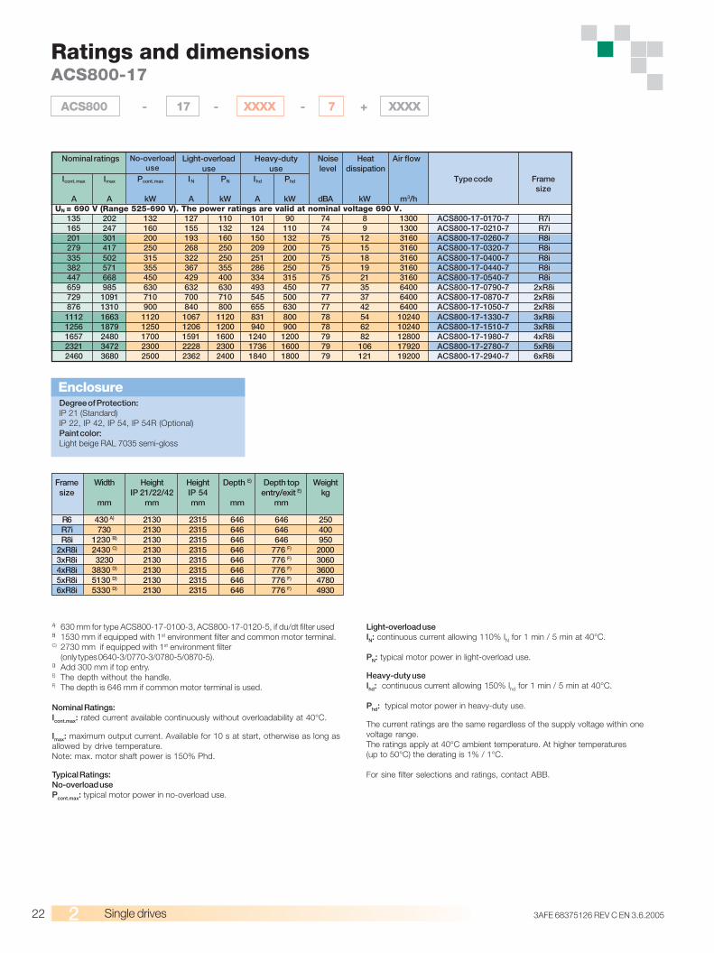
A A kW A kW A kW dBA kW m3/hUN = 690 V (Range 525-690 V). The power ratings are valid at nominal voltage 690 V.
135 202 132 127 110 101 90 74 8 1300 ACS800-17-0170-7 R7i165 247 160 155 132 124 110 74 9 1300 ACS800-17-0210-7 R7i201 301 200 193 160 150 132 75 12 3160 ACS800-17-0260-7 R8i279 417 250 268 250 209 200 75 15 3160 ACS800-17-0320-7 R8i335 502 315 322 250 251 200 75 18 3160 ACS800-17-0400-7 R8i382 571 355 367 355 286 250 75 19 3160 ACS800-17-0440-7 R8i447 668 450 429 400 334 315 75 21 3160 ACS800-17-0540-7 R8i659 985 630 632 630 493 450 77 35 6400 ACS800-17-0790-7 2xR8i729 1091 710 700 710 545 500 77 37 6400 ACS800-17-0870-7 2xR8i876 1310 900 840 800 655 630 77 42 6400 ACS800-17-1050-7 2xR8i1112 1663 1120 1067 1120 831 800 78 54 10240 ACS800-17-1330-7 3xR8i1256 1879 1250 1206 1200 940 900 78 62 10240 ACS800-17-1510-7 3xR8i1657 2480 1700 1591 1600 1240 1200 79 82 12800 ACS800-17-1980-7 4xR8i2321 3472 2300 2228 2300 1736 1600 79 106 17920 ACS800-17-2780-7 5xR8i2460 3680 2500 2362 2400 1840 1800 79 121 19200 ACS800-17-2940-7 6xR8i
Nominal ratings No-overloaduse
Light-overloaduse
Heavy-dutyuse
Noiselevel
Heatdissipation
Air flow
Ratings and dimensionsACS800-17
ACS800 - 17 - XXXX - 7 + XXXX
Degree of Protection:IP 21 (Standard)IP 22, IP 42, IP 54, IP 54R (Optional)Paint color:Light beige RAL 7035 semi-gloss
Enclosure
Frame Width Height Height Depth E) Depth top Weightsize IP 21/22/42 IP 54 entry/exit E) kg
mm mm mm mm mm
R6 430 A) 2130 2315 646 646 250R7i 730 2130 2315 646 646 400R8i 1230 B) 2130 2315 646 646 950
2xR8i 2430 C) 2130 2315 646 776 F) 20003xR8i 3230 2130 2315 646 776 F) 30604xR8i 3830 D) 2130 2315 646 776 F) 36005xR8i 5130 D) 2130 2315 646 776 F) 47806xR8i 5330 D) 2130 2315 646 776 F) 4930
Light-overload useIN: continuous current allowing 110% IN for 1 min / 5 min at 40°C.
PN: typical motor power in light-overload use.
Heavy-duty useIhd: continuous current allowing 150% Ihd for 1 min / 5 min at 40°C.
Phd: typical motor power in heavy-duty use.
The current ratings are the same regardless of the supply voltage within onevoltage range.The ratings apply at 40°C ambient temperature. At higher temperatures(up to 50°C) the derating is 1% / 1°C.
For sine filter selections and ratings, contact ABB.

233AFE 68375126 REV C EN 3.6.2005 Single drives
Cabinet-built low harmonic driveACS800-37, up to 2800 kW
Simple low harmonic solution
There is increasing concern among end users andpower companies about the harmful effects of harmon-ics. Harmonic distortion may disturb or even damagesensitive equipment connected in the same environ-ment. Harmonic standards are thus becoming stricterand there is a growing demand for low harmonicsolutions.
The ACS800-37 drive offers an easy solution to theproblem of harmonics. The solution itself is incorpo-rated in the drive, eliminating the need for anyadditional filtering equipment or complicated multi-pulse transformer arrangements.
Meets the strictest standards
The ACS800-37 eliminates low order harmonics withline converter DTC control, and high order harmonicswith an LCL line filter. The result is exceptionally lowharmonic content in the network; exceeding, e.g., therequirements set by standard IEEE519 even in theweakest network. The ACS800-37 provides you with asimple, compact solution to meet stringent powerquality standards.
Beats external solutions
The ACS800-37 does not require a dedicated multi-pulsetransformer and thus is simpler in terms of cablingarrangements and requires less floor space. Harmonicperformance is better than with 12- and 18-pulsesolutions. Passive or active external filtering devicesare avoided with the ACS800-37, making the solutioncompact and simple. Another advantage of the ACS800-37is that it always operates with power factor 1.
Extensive range of features
In line with other ACS800 cabinet-built drives, theACS800-37 offers a wide variety of standardized configu-rations to adapt to different application requirements.The smart module concept enables easy maintenanceand redundancy in the high power range.
Main standard features
■ Compact design■ IP 21 protection class■ Inbuilt low harmonic LCL filter■ EMC filter for 2nd environment, unrestricted distribu-
tion according to EN 61800-3 (option in frame size R6)■ Main switch with aR fuses (in frame sizes R6-R8i)■ Line contactor (in frame sizes R7i-R8i, option in
frame size R6)■ Removable air circuit breaker (in frame size nxR8i)■ Du/dt filters (in frame size nxR8i)■ Coated boards■ Extensive, programmable I/O■ Long lifetime cooling fan and capacitors■ Inputs galvanically isolated■ I/O and fieldbus extension slots inside■ Alphanumeric multilingual control panel with a
start-up assistant feature
Accessories for ACS800-37
■ Analogue and digital I/O extension modules■ ATEX approved motor protection■ Braking chopper and resistor■ Cabinet heater■ Customer terminal block■ Du/dt filters (in frame sizes R6-R8i)■ Earth fault monitoring for unearthed network■ EMC filter for 1st environment, restricted distribution
according to EN 61800-3■ Fieldbus modules■ IP 22, IP 42, IP 54 or IP 54R enclosure classes■ Emergency stop, category 0 or 1■ Marine construction■ Output for motor fan■ Pulse encoder interface module■ Prevention of unexpected start up of motor■ Top entry and exit of cables■ 1 or 2 thermistor relays■ 3, 5 or 8 Pt100 relays
Plus tailor made accessories through ABB's applicationengineering.
24 3AFE 68375126 REV C EN 3.6.2005Single drives
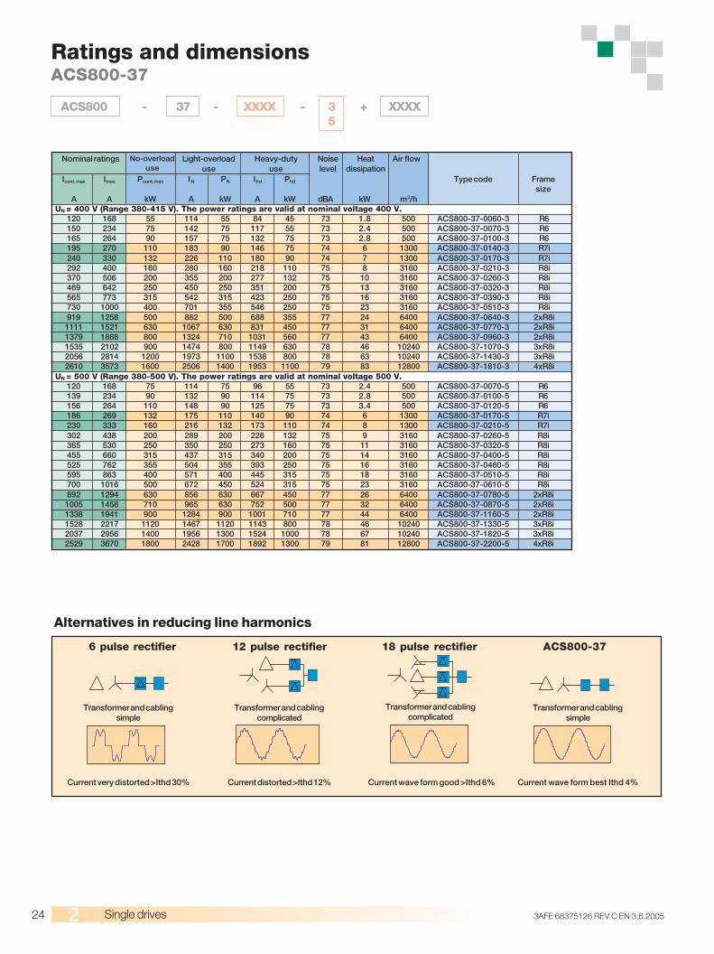
Ratings and dimensionsACS800-37
ACS800 - 37 - XXXX - 3 + XXXX5
Icont. max Imax Pcont. max IN PN Ihd Phd Type code Framesize
A A kW A kW A kW dBA kW m3/hUN = 400 V (Range 380-415 V). The power ratings are valid at nominal voltage 400 V.
120 168 55 114 55 84 45 73 1.8 500 ACS800-37-0060-3 R6150 234 75 142 75 117 55 73 2.4 500 ACS800-37-0070-3 R6165 264 90 157 75 132 75 73 2.8 500 ACS800-37-0100-3 R6195 270 110 183 90 146 75 74 6 1300 ACS800-37-0140-3 R7i240 330 132 226 110 180 90 74 7 1300 ACS800-37-0170-3 R7i292 400 160 280 160 218 110 75 8 3160 ACS800-37-0210-3 R8i370 506 200 355 200 277 132 75 10 3160 ACS800-37-0260-3 R8i469 642 250 450 250 351 200 75 13 3160 ACS800-37-0320-3 R8i565 773 315 542 315 423 250 75 16 3160 ACS800-37-0390-3 R8i730 1000 400 701 355 546 250 75 23 3160 ACS800-37-0510-3 R8i919 1258 500 882 500 688 355 77 24 6400 ACS800-37-0640-3 2xR8i1111 1521 630 1067 630 831 450 77 31 6400 ACS800-37-0770-3 2xR8i1379 1888 800 1324 710 1031 560 77 43 6400 ACS800-37-0960-3 2xR8i1535 2102 900 1474 800 1149 630 78 46 10240 ACS800-37-1070-3 3xR8i2056 2814 1200 1973 1100 1538 800 78 63 10240 ACS800-37-1430-3 3xR8i2610 3573 1600 2506 1400 1953 1100 79 83 12800 ACS800-37-1810-3 4xR8i
UN = 500 V (Range 380-500 V). The power ratings are valid at nominal voltage 500 V.120 168 75 114 75 96 55 73 2.4 500 ACS800-37-0070-5 R6139 234 90 132 90 114 75 73 2.8 500 ACS800-37-0100-5 R6156 264 110 148 90 125 75 73 3.4 500 ACS800-37-0120-5 R6186 269 132 175 110 140 90 74 6 1300 ACS800-37-0170-5 R7i230 333 160 216 132 173 110 74 8 1300 ACS800-37-0210-5 R7i302 438 200 289 200 226 132 75 9 3160 ACS800-37-0260-5 R8i365 530 250 350 250 273 160 75 11 3160 ACS800-37-0320-5 R8i455 660 315 437 315 340 200 75 14 3160 ACS800-37-0400-5 R8i525 762 355 504 355 393 250 75 16 3160 ACS800-37-0460-5 R8i595 863 400 571 400 445 315 75 18 3160 ACS800-37-0510-5 R8i700 1016 500 672 450 524 315 75 23 3160 ACS800-37-0610-5 R8i892 1294 630 856 630 667 450 77 26 6400 ACS800-37-0780-5 2xR8i1005 1458 710 965 630 752 500 77 32 6400 ACS800-37-0870-5 2xR8i1338 1941 900 1284 900 1001 710 77 44 6400 ACS800-37-1160-5 2xR8i1528 2217 1120 1467 1120 1143 800 78 46 10240 ACS800-37-1330-5 3xR8i2037 2956 1400 1956 1300 1524 1000 78 67 10240 ACS800-37-1820-5 3xR8i2529 3670 1800 2428 1700 1892 1300 79 81 12800 ACS800-37-2200-5 4xR8i
Nominal ratings No-overloaduse
Light-overloaduse
Heavy-dutyuse
Noiselevel
Heatdissipation
Air flow
6 pulse rectifier
Transformer and cablingsimple
Current very distorted >Ithd 30%
12 pulse rectifier
Transformer and cablingcomplicated
Current distorted >Ithd 12%
18 pulse rectifier
Transformer and cablingcomplicated
Current wave form good >Ithd 6%
ACS800-37
Transformer and cablingsimple
Current wave form best Ithd 4%
Alternatives in reducing line harmonics
253AFE 68375126 REV C EN 3.6.2005 Single drives
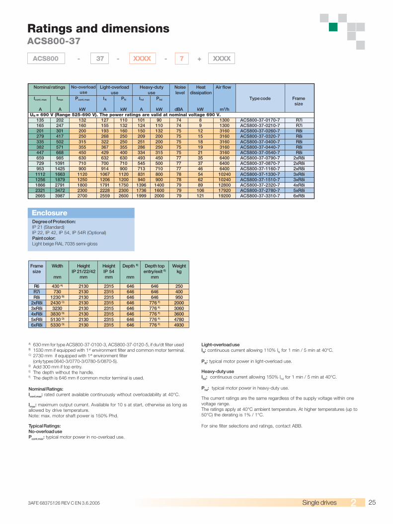
Ratings and dimensionsACS800-37
ACS800 - 37 - XXXX - 7 + XXXX
Icont. max Imax Pcont. max IN PN Ihd Phd Type code Framesize
A A kW A kW A kW dBA kW m3/hUN = 690 V (Range 525-690 V). The power ratings are valid at nominal voltage 690 V.
135 202 132 127 110 101 90 74 8 1300 ACS800-37-0170-7 R7i165 247 160 155 132 124 110 74 9 1300 ACS800-37-0210-7 R7i201 301 200 193 160 150 132 75 12 3160 ACS800-37-0260-7 R8i279 417 250 268 250 209 200 75 15 3160 ACS800-37-0320-7 R8i335 502 315 322 250 251 200 75 18 3160 ACS800-37-0400-7 R8i382 571 355 367 355 286 250 75 19 3160 ACS800-37-0440-7 R8i447 668 450 429 400 334 315 75 21 3160 ACS800-37-0540-7 R8i659 985 630 632 630 493 450 77 35 6400 ACS800-37-0790-7 2xR8i729 1091 710 700 710 545 500 77 37 6400 ACS800-37-0870-7 2xR8i953 1425 900 914 900 713 710 77 46 6400 ACS800-37-1160-7 2xR8i1112 1663 1120 1067 1120 831 800 78 54 10240 ACS800-37-1330-7 3xR8i1256 1879 1250 1206 1200 940 900 78 62 10240 ACS800-37-1510-7 3xR8i1866 2791 1800 1791 1750 1396 1400 79 89 12800 ACS800-37-2320-7 4xR8i2321 3472 2300 2228 2300 1736 1600 79 106 17920 ACS800-37-2780-7 5xR8i2665 3987 2700 2559 2600 1999 2000 79 121 19200 ACS800-37-3310-7 6xR8i
Nominal ratings No-overloaduse
Light-overloaduse
Heavy-dutyuse
Noiselevel
Heatdissipation
Air flow
Degree of Protection:IP 21 (Standard)IP 22, IP 42, IP 54, IP 54R (Optional)Paint color:Light beige RAL 7035 semi-gloss
Enclosure
A) 630 mm for type ACS800-37-0100-3, ACS800-37-0120-5, if du/dt filter usedB) 1530 mm if equipped with 1st environment filter and common motor terminal.C) 2730 mm if equipped with 1st environment filter
(only types 0640-3/0770-3/0780-5/0870-5).D) Add 300 mm if top entry.E) The depth without the handle.F) The depth is 646 mm if common motor terminal is used.
Nominal Ratings:Icont.max: rated current available continuously without overloadability at 40°C.
Imax: maximum output current. Available for 10 s at start, otherwise as long asallowed by drive temperature.Note: max. motor shaft power is 150% Phd.
Typical Ratings:No-overload usePcont.max: typical motor power in no-overload use.
Light-overload useIN: continuous current allowing 110% IN for 1 min / 5 min at 40°C.
PN: typical motor power in light-overload use.
Heavy-duty useIhd: continuous current allowing 150% Ihd for 1 min / 5 min at 40°C.
Phd: typical motor power in heavy-duty use.
The current ratings are the same regardless of the supply voltage within onevoltage range.The ratings apply at 40°C ambient temperature. At higher temperatures (up to50°C) the derating is 1% / 1°C.
For sine filter selections and ratings, contact ABB.
Frame Width Height Height Depth E) Depth top Weightsize IP 21/22/42 IP 54 entry/exit E) kg
mm mm mm mm mm
R6 430 A) 2130 2315 646 646 250R7i 730 2130 2315 646 646 400R8i 1230 B) 2130 2315 646 646 950
2xR8i 2430 C) 2130 2315 646 776 F) 20003xR8i 3230 2130 2315 646 776 F) 30604xR8i 3830 D) 2130 2315 646 776 F) 36005xR8i 5130 D) 2130 2315 646 776 F) 47806xR8i 5330 D) 2130 2315 646 776 F) 4930
26 3AFE 68375126 REV C EN 3.6.2005Hardware options
Brake options
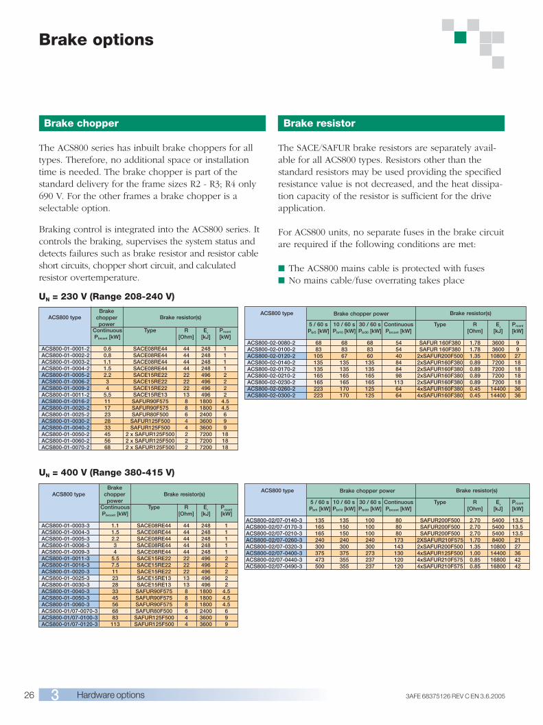
Brake chopper
The ACS800 series has inbuilt brake choppers for alltypes. Therefore, no additional space or installationtime is needed. The brake chopper is part of thestandard delivery for the frame sizes R2 - R3; R4 only690 V. For the other frames a brake chopper is aselectable option.
Braking control is integrated into the ACS800 series. Itcontrols the braking, supervises the system status anddetects failures such as brake resistor and resistor cableshort circuits, chopper short circuit, and calculatedresistor overtemperature.
Continuous Type R Er
Prcont
Pbrcont [kW] [Ohm] [kJ] [kW]
ACS800-01-0001-2 0.6 SACE08RE44 44 248 1ACS800-01-0002-2 0.8 SACE08RE44 44 248 1ACS800-01-0003-2 1.1 SACE08RE44 44 248 1ACS800-01-0004-2 1.5 SACE08RE44 44 248 1ACS800-01-0005-2 2.2 SACE15RE22 22 496 2ACS800-01-0006-2 3 SACE15RE22 22 496 2ACS800-01-0009-2 4 SACE15RE22 22 496 2ACS800-01-0011-2 5.5 SACE15RE13 13 496 2ACS800-01-0016-2 11 SAFUR90F575 8 1800 4.5ACS800-01-0020-2 17 SAFUR90F575 8 1800 4.5ACS800-01-0025-2 23 SAFUR80F500 6 2400 6ACS800-01-0030-2 28 SAFUR125F500 4 3600 9ACS800-01-0040-2 33 SAFUR125F500 4 3600 9ACS800-01-0050-2 45 2 x SAFUR125F500 2 7200 18ACS800-01-0060-2 56 2 x SAFUR125F500 2 7200 18ACS800-01-0070-2 68 2 x SAFUR125F500 2 7200 18
UN = 230 V (Range 208-240 V)
5 / 60 s 10 / 60 s 30 / 60 s Continuous Type R Er
Prcont
Pbr5 [kW] Pbr10 [kW] Pbr30 [kW] Pbrcont [kW] [Ohm] [kJ] [kW]
ACS800-02-0080-2 68 68 68 54 SAFUR 160F380 1.78 3600 9ACS800-02-0100-2 83 83 83 54 SAFUR 160F380 1.78 3600 9ACS800-02-0120-2 105 67 60 40 2xSAFUR200F500 1.35 10800 27ACS800-02-0140-2 135 135 135 84 2xSAFUR160F380 0.89 7200 18ACS800-02-0170-2 135 135 135 84 2xSAFUR160F380 0.89 7200 18ACS800-02-0210-2 165 165 165 98 2xSAFUR160F380 0.89 7200 18ACS800-02-0230-2 165 165 165 113 2xSAFUR160F380 0.89 7200 18ACS800-02-0260-2 223 170 125 64 4xSAFUR160F380 0.45 14400 36ACS800-02-0300-2 223 170 125 64 4xSAFUR160F380 0.45 14400 36
UN = 400 V (Range 380-415 V)
Brake resistor
The SACE/SAFUR brake resistors are separately avail-able for all ACS800 types. Resistors other than thestandard resistors may be used providing the specifiedresistance value is not decreased, and the heat dissipa-tion capacity of the resistor is sufficient for the driveapplication.
For ACS800 units, no separate fuses in the brake circuitare required if the following conditions are met:
■ The ACS800 mains cable is protected with fuses■ No mains cable/fuse overrating takes place
ACS800 typeBrake
chopperpower
Brake resistor(s)
ACS800 type Brake resistor(s)Brake chopper power
5 / 60 s 10 / 60 s 30 / 60 s Continuous Type R Er Prcont
Pbr5 [kW] Pbr10 [kW] Pbr30 [kW] Pbrcont [kW] [Ohm] [kJ] [kW]
ACS800-02/07-0140-3 135 135 100 80 SAFUR200F500 2.70 5400 13.5ACS800-02/07-0170-3 165 150 100 80 SAFUR200F500 2.70 5400 13.5ACS800-02/07-0210-3 165 150 100 80 SAFUR200F500 2.70 5400 13.5ACS800-02/07-0260-3 240 240 240 173 2XSAFUR210F575 1.70 8400 21ACS800-02/07-0320-3 300 300 300 143 2xSAFUR200F500 1.35 10800 27ACS800-02/07-0400-3 375 375 273 130 4xSAFUR125F500 1.00 14400 36ACS800-02/07-0440-3 473 355 237 120 4xSAFUR210F575 0.85 16800 42ACS800-02/07-0490-3 500 355 237 120 4xSAFUR210F575 0.85 16800 42
Brake resistor(s)ACS800 typeBrake
chopperpower
Continuous Type R Er Prcont
Pbrcont [kW] [Ohm] [kJ] [kW]
ACS800-01-0003-3 1.1 SACE08RE44 44 248 1ACS800-01-0004-3 1.5 SACE08RE44 44 248 1ACS800-01-0005-3 2.2 SACE08RE44 44 248 1ACS800-01-0006-3 3 SACE08RE44 44 248 1ACS800-01-0009-3 4 SACE08RE44 44 248 1ACS800-01-0011-3 5.5 SACE15RE22 22 496 2ACS800-01-0016-3 7.5 SACE15RE22 22 496 2ACS800-01-0020-3 11 SACE15RE22 22 496 2ACS800-01-0025-3 23 SACE15RE13 13 496 2ACS800-01-0030-3 28 SACE15RE13 13 496 2ACS800-01-0040-3 33 SAFUR90F575 8 1800 4.5ACS800-01-0050-3 45 SAFUR90F575 8 1800 4.5ACS800-01-0060-3 56 SAFUR90F575 8 1800 4.5ACS800-01/07-0070-3 68 SAFUR80F500 6 2400 6ACS800-01/07-0100-3 83 SAFUR125F500 4 3600 9ACS800-01/07-0120-3 113 SAFUR125F500 4 3600 9
ACS800 type Brake resistor(s)Brake chopper power
273AFE 68375126 REV C EN 3.6.2005 Hardware options
Brake options
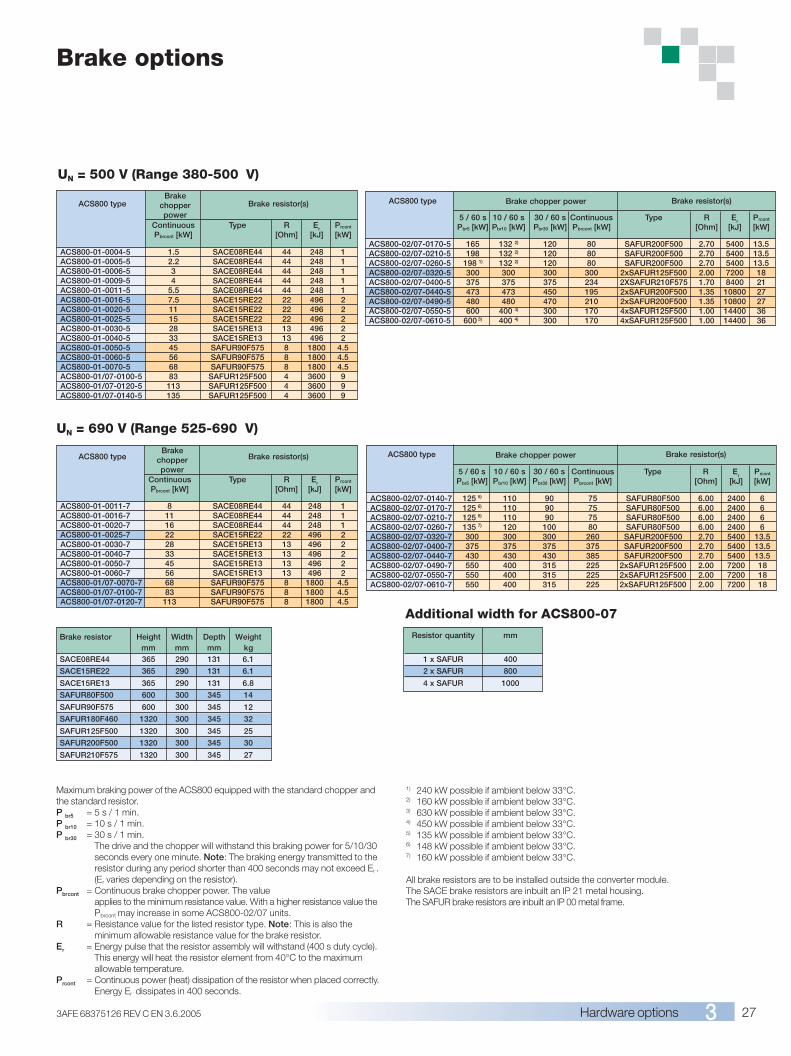
UN = 500 V (Range 380-500 V)
UN = 690 V (Range 525-690 V)
Maximum braking power of the ACS800 equipped with the standard chopper andthe standard resistor.P br5 = 5 s / 1 min.P br10 = 10 s / 1 min.P br30 = 30 s / 1 min.
The drive and the chopper will withstand this braking power for 5/10/30seconds every one minute. Note: The braking energy transmitted to theresistor during any period shorter than 400 seconds may not exceed Er .(Er varies depending on the resistor).
Pbrcont = Continuous brake chopper power. The valueapplies to the minimum resistance value. With a higher resistance value thePbrcont may increase in some ACS800-02/07 units.
R = Resistance value for the listed resistor type. Note: This is also theminimum allowable resistance value for the brake resistor.
Er = Energy pulse that the resistor assembly will withstand (400 s duty cycle).This energy will heat the resistor element from 40°C to the maximumallowable temperature.
Prcont = Continuous power (heat) dissipation of the resistor when placed correctly.Energy Er dissipates in 400 seconds.
Continuous Type R Er Prcont
Pbrcont [kW] [Ohm] [kJ] [kW]
ACS800-01-0004-5 1.5 SACE08RE44 44 248 1ACS800-01-0005-5 2.2 SACE08RE44 44 248 1ACS800-01-0006-5 3 SACE08RE44 44 248 1ACS800-01-0009-5 4 SACE08RE44 44 248 1ACS800-01-0011-5 5.5 SACE08RE44 44 248 1ACS800-01-0016-5 7.5 SACE15RE22 22 496 2ACS800-01-0020-5 11 SACE15RE22 22 496 2ACS800-01-0025-5 15 SACE15RE22 22 496 2ACS800-01-0030-5 28 SACE15RE13 13 496 2ACS800-01-0040-5 33 SACE15RE13 13 496 2ACS800-01-0050-5 45 SAFUR90F575 8 1800 4.5ACS800-01-0060-5 56 SAFUR90F575 8 1800 4.5ACS800-01-0070-5 68 SAFUR90F575 8 1800 4.5ACS800-01/07-0100-5 83 SAFUR125F500 4 3600 9ACS800-01/07-0120-5 113 SAFUR125F500 4 3600 9ACS800-01/07-0140-5 135 SAFUR125F500 4 3600 9
5 / 60 s 10 / 60 s 30 / 60 s Continuous Type R Er Prcont
Pbr5 [kW] Pbr10 [kW] Pbr30 [kW] Pbrcont [kW] [Ohm] [kJ] [kW]
ACS800-02/07-0170-5 165 132 2) 120 80 SAFUR200F500 2.70 5400 13.5ACS800-02/07-0210-5 198 132 2) 120 80 SAFUR200F500 2.70 5400 13.5ACS800-02/07-0260-5 198 1) 132 2) 120 80 SAFUR200F500 2.70 5400 13.5ACS800-02/07-0320-5 300 300 300 300 2xSAFUR125F500 2.00 7200 18ACS800-02/07-0400-5 375 375 375 234 2XSAFUR210F575 1.70 8400 21ACS800-02/07-0440-5 473 473 450 195 2xSAFUR200F500 1.35 10800 27ACS800-02/07-0490-5 480 480 470 210 2xSAFUR200F500 1.35 10800 27ACS800-02/07-0550-5 600 400 4) 300 170 4xSAFUR125F500 1.00 14400 36ACS800-02/07-0610-5 600 3) 400 4) 300 170 4xSAFUR125F500 1.00 14400 36
Continuous Type R Er Prcont
Pbrcont [kW] [Ohm] [kJ] [kW]
ACS800-01-0011-7 8 SACE08RE44 44 248 1ACS800-01-0016-7 11 SACE08RE44 44 248 1ACS800-01-0020-7 16 SACE08RE44 44 248 1ACS800-01-0025-7 22 SACE15RE22 22 496 2ACS800-01-0030-7 28 SACE15RE13 13 496 2ACS800-01-0040-7 33 SACE15RE13 13 496 2ACS800-01-0050-7 45 SACE15RE13 13 496 2ACS800-01-0060-7 56 SACE15RE13 13 496 2ACS800-01/07-0070-7 68 SAFUR90F575 8 1800 4.5ACS800-01/07-0100-7 83 SAFUR90F575 8 1800 4.5ACS800-01/07-0120-7 113 SAFUR90F575 8 1800 4.5
5 / 60 s 10 / 60 s 30 / 60 s Continuous Type R Er
Prcont
Pbr5 [kW] Pbr10 [kW] Pbr30 [kW] Pbrcont [kW] [Ohm] [kJ] [kW]
ACS800-02/07-0140-7 125 5) 110 90 75 SAFUR80F500 6.00 2400 6ACS800-02/07-0170-7 125 6) 110 90 75 SAFUR80F500 6.00 2400 6ACS800-02/07-0210-7 125 6) 110 90 75 SAFUR80F500 6.00 2400 6ACS800-02/07-0260-7 135 7) 120 100 80 SAFUR80F500 6.00 2400 6ACS800-02/07-0320-7 300 300 300 260 SAFUR200F500 2.70 5400 13.5ACS800-02/07-0400-7 375 375 375 375 SAFUR200F500 2.70 5400 13.5ACS800-02/07-0440-7 430 430 430 385 SAFUR200F500 2.70 5400 13.5ACS800-02/07-0490-7 550 400 315 225 2xSAFUR125F500 2.00 7200 18ACS800-02/07-0550-7 550 400 315 225 2xSAFUR125F500 2.00 7200 18ACS800-02/07-0610-7 550 400 315 225 2xSAFUR125F500 2.00 7200 18
1) 240 kW possible if ambient below 33°C.2) 160 kW possible if ambient below 33°C.3) 630 kW possible if ambient below 33°C.4) 450 kW possible if ambient below 33°C.5) 135 kW possible if ambient below 33°C.6) 148 kW possible if ambient below 33°C.7) 160 kW possible if ambient below 33°C.
All brake resistors are to be installed outside the converter module.The SACE brake resistors are inbuilt an IP 21 metal housing.The SAFUR brake resistors are inbuilt an IP 00 metal frame.
Brake resistor Height Width Depth Weightmm mm mm kg
SACE08RE44 365 290 131 6.1
SACE15RE22 365 290 131 6.1
SACE15RE13 365 290 131 6.8
SAFUR80F500 600 300 345 14
SAFUR90F575 600 300 345 12
SAFUR180F460 1320 300 345 32
SAFUR125F500 1320 300 345 25
SAFUR200F500 1320 300 345 30
SAFUR210F575 1320 300 345 27
ACS800 type Brake resistor(s)Brake
chopperpower
ACS800 type Brake resistor(s)Brake
chopperpower
ACS800 type Brake resistor(s)Brake chopper power
ACS800 type Brake resistor(s)Brake chopper power
Resistor quantity mm
1 x SAFUR 400
2 x SAFUR 800
4 x SAFUR 1000
Additional width for ACS800-07
28 3AFE 68375126 REV C EN 3.6.2005Hardware options
Brake options
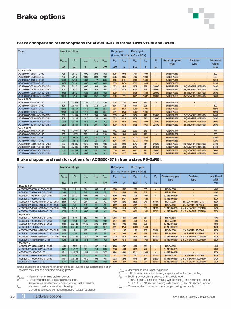
Brake choppers and resistors for larger types are available as customised option.The drive may limit the available braking power.
Pbr.max = Maximum short time braking power.R = Recommended braking resistor resistance.
Also nominal resistance of corresponding SAFUR resistor.Imax = Maximum peak current during braking.
Current is achieved with recommended resistor resistance.
Pbr. max R Imax Irms Pcont. Pbr. Irms Pbr. Irms Er Brake chopper Resistor Additionaltype type width
kW ohm A A kW kW A kW A kJ mmUN = 400 VACS800-07-0610-3+D150 706 2x1.2 1090 298 192 606 936 706 1090 - 2xNBRA659 - 800ACS800-07-0770-3+D150 706 2x1.2 1090 298 192 606 936 706 1090 - 2xNBRA659 - 800ACS800-07-0870-3+D150 1058 3x1.2 1635 447 288 909 1404 1059 1635 - 3xNBRA659 - 1200ACS800-07-1030-3+D150 1058 3x1.2 1635 447 288 909 1404 1059 1635 - 3xNBRA659 - 1200ACS800-07-0610-3+D150+D151 706 2x1.2 1090 168 108 333 514 575 888 24000 2xNBRA659 2x(2xSAFUR180F460) 2400ACS800-07-0770-3+D150+D151 706 2x1.2 1090 168 108 333 514 575 888 24000 2xNBRA659 2x(2xSAFUR180F460) 2400ACS800-07-0870-3+D150+D151 1058 3x1.2 1635 252 162 500 771 862 1332 36000 3xNBRA659 3x(2xSAFUR180F460) 3600ACS800-07-1030-3+D150+D151 1058 3x1.2 1635 252 162 500 771 862 1332 36000 3xNBRA659 3x(2xSAFUR180F460) 3600UN = 500 VACS800-07-0760-5+D150 806 2x1.43 1142 272 218 634 782 806 996 - 2xNBRA659 - 800ACS800-07-0910-5+D150 806 2x1.43 1142 272 218 634 782 806 996 - 2xNBRA659 - 800ACS800-07-1090-5+D150 1208 3x1.43 1713 408 327 951 1173 1209 1494 - 3xNBRA659 - 1200ACS800-07-1210-5+D150 1208 3x1.43 1713 408 327 951 1173 1209 1494 - 3xNBRA659 - 1200ACS800-07-0760-5+D150+D151 806 2x1.35 1210 134 108 333 412 575 710 21600 2xNBRA659 2x(2xSAFUR200F500) 2400ACS800-07-0910-5+D150+D151 806 2x1.35 1210 134 108 333 412 575 710 21600 2xNBRA659 2x(2xSAFUR200F500) 2400ACS800-07-1090-5+D150+D151 1208 3x1.35 1815 201 162 500 618 862 1065 32400 3xNBRA659 3x(2xSAFUR200F500) 3600ACS800-07-1210-5+D150+D151 1208 3x1.35 1815 201 162 500 618 862 1065 32400 3xNBRA659 3x(2xSAFUR200F500) 3600UN = 690 VACS800-07-0750-7+D150 807 2x2.72 828 214 238 596 534 808 722 - 2xNBRA669 - 800ACS800-07-0870-7+D150 807 2x2.72 828 214 238 596 534 808 722 - 2xNBRA669 - 800ACS800-07-1060-7+D150 1211 3x2.72 1242 321 357 894 801 1212 1083 - 3xNBRA669 - 1200ACS800-07-1160-7+D150 1211 3x2.72 1242 321 357 894 801 1212 1083 - 3xNBRA669 - 1200ACS800-07-0750-7+D150+D151 807 2x1.35 1670 194 108 333 298 575 514 21600 2xNBRA669 2x(2xSAFUR200F500) 2400ACS800-07-0870-7+D150+D151 807 2x1.35 1670 194 108 333 298 575 514 21600 2xNBRA669 2x(2xSAFUR200F500) 2400ACS800-07-1060-7+D150+D151 1211 3x1.35 2505 291 162 500 447 862 771 32400 3xNBRA669 3x(2xSAFUR200F500) 3600ACS800-07-1160-7+D150+D151 1211 3x1.35 2505 291 162 500 447 862 771 32400 3xNBRA669 3x(2xSAFUR200F500) 3600
Brake chopper and resistor options for ACS800-07 in frame sizes 2xR8i and 3xR8i.
Type Nominal ratings Duty cycle Duty cycle
(1 min / 5 min) (10 s / 60 s)
Brake chopper and resistor options for ACS800-37 in frame sizes R6-2xR8i.
Pbr. max R Imax Irms Pcont. Pbr.
Irms Pbr. Irms Er Brake chopper Resistor Additionaltype type width
kW ohm A A kW kW A kW A kJ mmUN = 400 VACS800-37-0060...0170-3+D150 230 1.7 384 109 70 230 355 230 355 - NBRA658 - 400ACS800-37-0210...0510-3+D150 353 1.2 545 149 96 303 468 353 545 - NBRA659 - 400ACS800-37-0640...0770-3+D150 706 2x1.2 1090 298 192 606 936 706 1090 - 2 x NBRA659 - 800ACS800-37-0960-3+D150 1058 3x1.2 1635 447 288 909 1404 1059 1635 - 3 x NBRA659 - 1200ACS800-37-0060...0170-3+D150+D151 230 1.7 384 65 42 130 200 224 346 8400 NBRA658 2 x SAFUR210F575 1200ACS800-37-0210...0510-3+D150+D151 353 1.2 545 84 54 287 444 287 444 12000 NBRA659 2 x SAFUR180F460 1200ACS800-37-0640...0770-3+D150+D151 706 2x1.2 1090 168 108 333 514 575 888 24000 2 x NBRA659 2 x (2 x SAFUR180F460) 2400ACS800-37-0960-3+D150+D151 1058 3x1.2 1635 252 162 500 771 862 1332 36000 3 x NBRA659 3 x (2 x SAFUR180F460) 3600UN=500 VACS800-37-0070...0210-5+D150 268 2.15 380 101 81 268 331 268 331 - NBRA658 - 400ACS800-37-0260...0610-5+D150 403 1.43 571 136 109 317 391 403 498 - NBRA659 - 400ACS800-37-0780...0870-5+D150 806 2x1.43 1142 272 218 634 782 806 996 - 2 x NBRA659 - 800ACS800-37-1160-5+D150 1208 3x1.43 1713 408 327 951 1173 1209 1494 - 3 x NBRA659 - 1200ACS800-37-0070...0210-5+D150+D151 268 2 408 45 36 111 137 192 237 7200 NBRA658 2 x SAFUR125F500 1200ACS800-37-0260...0610-5+D150+D151 403 1.35 605 67 54 167 206 287 355 10800 NBRA659 2 x SAFUR200F500 1200ACS800-37-0780...0870-5+D150+D151 806 2x1.35 1210 134 108 333 412 575 710 21600 2 x NBRA659 2 x (2 x SAFUR200F500) 2400ACS800-37-1160+D150+D151 1208 3x1.35 1815 201 162 500 618 862 1065 32400 3 x NBRA659 3 x (2 x SAFUR200F500) 3600UN=690 VACS800-37-0170...0540-7+D150 404 2.72 414 107 119 298 267 404 361 - NBRA669 - 400ACS800-37-0790...0870-7+D150 807 2x2.72 828 214 238 596 534 808 722 - 2 x NBRA669 - 800ACS800-37-1160-7+D150 1211 3x2.72 1242 321 357 894 801 1212 1083 - 3 x NBRA669 - 1200ACS800-37-0170...0540-7+D150 404 1.35 835 97 54 167 149 287 257 10800 NBRA669 2 x SAFUR200F500 1200ACS800-37-0790...0870-7+D150 807 2x1.35 1670 194 108 333 298 575 514 21600 2 x NBRA669 2 x (2 x SAFUR200F500) 2400ACS800-37-1160-7+D150 1211 3x1.35 2505 291 162 500 447 862 771 32400 3 x NBRA669 3 x (2 x SAFUR200F500) 3600
Type Nominal ratings Duty cycle Duty cycle
(1 min / 5 min) (10 s / 60 s)
Pcont. = Maximum continous braking power.Er = SAFUR resistor nominal braking capacity without forced cooling.Pbr. = Braking power during corresponding cycle load:
1 min / 5 min = 1 minute braking with power Pbr. and 4 minutes unload.10 s / 60 s = 10 second braking with power Pbr. and 50 seconds unload.
Irms = Corresponding rms current per chopper during load cycle.
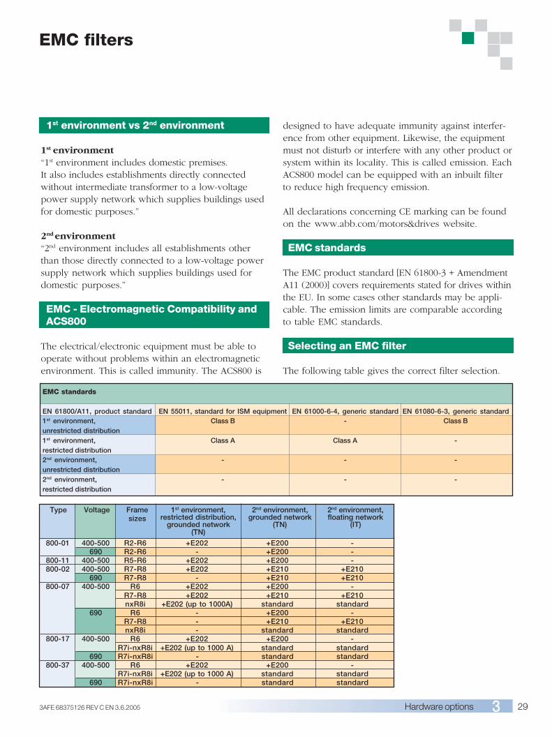
293AFE 68375126 REV C EN 3.6.2005 Hardware options
EMC filters
800-01 400-500 R2-R6 +E202 +E200 -690 R2-R6 - +E200 -
800-11 400-500 R5-R6 +E202 +E200 -800-02 400-500 R7-R8 +E202 +E210 +E210
690 R7-R8 - +E210 +E210800-07 400-500 R6 +E202 +E200 -
R7-R8 +E202 +E210 +E210nxR8i +E202 (up to 1000A) standard standard
690 R6 - +E200 -R7-R8 - +E210 +E210nxR8i - standard standard
800-17 400-500 R6 +E202 +E200 -R7i-nxR8i +E202 (up to 1000 A) standard standard
690 R7i-nxR8i - standard standard800-37 400-500 R6 +E202 +E200 -
R7i-nxR8i +E202 (up to 1000 A) standard standard690 R7i-nxR8i - standard standard
Type Voltage Framesizes
1st environment,restricted distribution,
grounded network(TN)
2nd environment,grounded network
(TN)
2nd environment,floating network
(IT)
EMC standards
EN 61800/A11, product standard EN 55011, standard for ISM equipment EN 61000-6-4, generic standard EN 61080-6-3, generic standard1st environment, Class B - Class Bunrestricted distribution1st environment, Class A Class A -restricted distribution2nd environment, - - -unrestricted distribution2nd environment, - - -restricted distribution
1st environment vs 2nd environment
1st environment“1st environment includes domestic premises.It also includes establishments directly connectedwithout intermediate transformer to a low-voltagepower supply network which supplies buildings usedfor domestic purposes.”
2nd environment“2nd environment includes all establishments otherthan those directly connected to a low-voltage powersupply network which supplies buildings used fordomestic purposes.”
EMC - Electromagnetic Compatibility andACS800
The electrical/electronic equipment must be able tooperate without problems within an electromagneticenvironment. This is called immunity. The ACS800 is
designed to have adequate immunity against interfer-ence from other equipment. Likewise, the equipmentmust not disturb or interfere with any other product orsystem within its locality. This is called emission. EachACS800 model can be equipped with an inbuilt filterto reduce high frequency emission.
All declarations concerning CE marking can be foundon the www.abb.com/motors&drives website.
EMC standards
The EMC product standard [EN 61800-3 + AmendmentA11 (2000)] covers requirements stated for drives withinthe EU. In some cases other standards may be appli-cable. The emission limits are comparable accordingto table EMC standards.
Selecting an EMC filter
The following table gives the correct filter selection.

30 3AFE 68375126 REV C EN 3.6.2005Hardware options
Sine filters
ABB sine filter solution
The ACS800 sine filter solution is an ACS800 industrialdrive equipped with a sine filter. It enjoys most of thepremium features of the standard ACS800 industrialdrive. The LC filter suppresses the high frequencycomponents of the output voltage.
Main features
■ Optimized LC design that takes into accountswitching frequency, voltage drop and filteringcharacteristics
■ Proven technology as ABB has delivered hundredsof sine filter solutions over the last 20 years
■ Cost effective solution■ Standard software has all the parameters that need
to be set
This means that the output voltage waveform is almostsinusoidal without high voltage peaks.
Filters are available in IP 00 degree of protection overthe whole power range. The ACS800-01 power rangehas also IP 23 filters available. The ACS800-07 sinefilter drives are complete cabinet-built units.
The ABB sine filter solution can be used in a variety ofapplications:■ Motor does not have adequate insulation for VSD duty■ Total motor cable length is long e.g. there are a
number of parallel motors■ Step-up applications e.g. medium voltage motor
needs to be driven■ Step-down applications■ There are industry specific requirements for peak
voltage level and voltage rise time■ Motor noise needs to be reduced■ Maximum safety and reliability is needed in e.g. EX
applications■ Submersible pumps with long motor cables e.g. in
the oil industry
FeatureSinusoidal outputvoltage
AP programming,advanced IR-compensation andflux control
BenefitNo additional stresson the motorinsulation: non-VSDcompliant motors canbe used, motorreliability and lifetimeare maximized.Allows the use oftransformers in thedrive output to matchany required motorvoltage.
Standard distributiontransformer can beused in step-upsolutions.
Less motor noise.
The effects of loadchanges to motorvoltage can becompensated i.e. themotor always has theoptimum voltage.
Note
Voltage drop at motorcable can be compen-sated with transformeri.e. there are norestrictions to motorcable length.
High starting torque isavailable with specialtransformer design.
Usually the motor fanis the biggest noisesource with sine filtersolutions.
Scalar control isrequired with sinefilters.
filter
2-13.8 kV AC
690 V AC
StepDowntrans-former
Step Uptrans-former
ACS800 Sinefilter 2-13.8 kV AC

313AFE 68375126 REV C EN 3.6.2005 Hardware options
Sine filtersTypes and ratings for ACS800-01 and ACS800-02
Icont. max Pcont. max Noise Heat Air flow Type code Filter IP class Filter Filter Filter Filterlevel dissipation size height width depth weight
A kW dB W m3/h mm mm mm kgUN = 400 V (Range 380-415 V). The power ratings are valid at nominal voltage 400 V.
8.5 3 67 180 35 1) ACS800-01-0005-3 NSIN 0006-5 IP00/IP23 160/234 155/230 120/170 6/919 7.5 68 350 69 1) ACS800-01-0011-3 NSIN 0016-5 IP00/IP23 280/460 240/470 190/270 15/2625 11 68 450 69 1) ACS800-01-0016-3 NSIN 0020-5 IP00/IP23 280/460 240/470 200/270 19/3033 15 68 560 69 1) ACS800-01-0020-3 NSIN 0025-5 IP00/IP23 280/460 240/470 210/270 21/3244 22 69 630 103 1) ACS800-01-0025-3 NSIN 0030-5 IP00/IP23 280/460 240/470 220/270 26/3754 26 69 730 103 1) ACS800-01-0030-3 NSIN 0040-5 IP00/IP23 315/460 300/470 228/270 34/4572 35 73 950 250 1) ACS800-01-0040-3 NSIN 0050-5 IP00/IP23 315/510 300/580 240/325 37/5386 42 73 1100 250 1) ACS800-01-0050-3 NSIN 0060-5 IP00/IP23 320/510 300/580 270/325 53/69102 52 73 1500 250 1) ACS800-01-0060-3 NSIN 0070-5 IP00/IP23 415/510 360/580 210/325 66/82141 71 75 1800 405 1) ACS800-01-0070-3 NSIN 0100-5 IP00/IP23 415/510 360/580 225/325 69/85164 84 75 2200 405 1) ACS800-01-0100-3 NSIN 0120-5 IP00/IP23 415/620 360/700 240/425 75/105199 102 75 2700 405 1) ACS800-01-0120-3 NSIN 0140-5 IP00/IP23 450/620 400/700 500/525 120/165206 100 79 4100 1240 2) ACS800-02-0140-3 NSIN 0315-6 3) IP00 2060 400 600 230248 120 79 4900 1240 2) ACS800-02-0170-3 NSIN 0315-6 3) IP00 2060 400 600 230266 130 79 5600 1240 2) ACS800-02-0210-3 NSIN 0315-6 3) IP00 2060 400 600 230445 215 80 8800 1920 2) ACS800-02-0260-3 NSIN 0485-6 3) IP00 2060 400 600 250521 250 80 9700 3220 2) ACS800-02-0320-3 NSIN 0900-6 3) IP00 2120 1000 600 690602 295 80 11100 3220 2) ACS800-02-0400-3 NSIN 0900-6 3) IP00 2120 1000 600 690693 340 80 12100 3220 2) ACS800-02-0440-3 NSIN 0900-6 3) IP00 2120 1000 600 690720 350 80 12600 3220 2) ACS800-02-0490-3 NSIN 0900-6 3) IP00 2120 1000 600 690
UN = 500 V (Range 380-500 V). The power ratings are valid at nominal voltage 500 V.8.1 4.4 67 300 35 1) ACS800-01-0006-5 NSIN 0006-5 IP00/IP23 160/234 155/230 120/170 6/919 11 68 590 69 1) ACS800-01-0016-5 NSIN 0016-5 IP00/IP23 280/460 240/470 190/270 15/2625 15 68 780 69 1) ACS800-01-0020-5 NSIN 0020-5 IP00/IP23 280/460 240/470 200/270 19/3033 20 68 1000 69 1) ACS800-01-0025-5 NSIN 0025-5 IP00/IP23 280/460 240/470 210/270 21/3242 26 69 1100 103 1) ACS800-01-0030-5 NSIN 0030-5 IP00/IP23 280/460 240/470 220/270 26/3747 29 69 1400 103 1) ACS800-01-0040-5 NSIN 0040-5 IP00/IP23 315/460 300/470 228/270 34/4565 40 73 1800 250 1) ACS800-01-0050-5 NSIN 0050-5 IP00/IP23 315/510 300/580 240/325 37/5379 48 73 2200 250 1) ACS800-01-0060-5 NSIN 0060-5 IP00/IP23 320/510 300/580 270/325 53/6994 60 73 2600 250 1) ACS800-01-0070-5 NSIN 0070-5 IP00/IP23 415/510 360/580 210/325 66/82124 78 75 3400 405 1) ACS800-01-0100-5 NSIN 0100-5 IP00/IP23 415/510 360/580 225/325 69/85155 99 75 4300 405 1) ACS800-01-0120-5 NSIN 0120-5 IP00/IP23 415/620 360/700 240/425 75/105177 114 75 5400 405 1) ACS800-01-0140-5 NSIN 0140-5 IP00/IP23 450/620 400/700 500/525 120/165196 125 79 4300 1240 2) ACS800-02-0170-5 NSIN 0315-6 3) IP00 2060 400 600 230245 150 79 5400 1240 2) ACS800-02-0210-5 NSIN 0315-6 3) IP00 2060 400 600 230258 160 79 6200 1240 2) ACS800-02-0260-5 NSIN 0315-6 3) IP00 2060 400 600 230440 275 80 9600 1920 2) ACS800-02-0320-5 NSIN 0485-6 3) IP00 2060 400 600 250515 320 80 11100 3220 2) ACS800-02-0400-5 NSIN 0900-6 3) IP00 2120 1000 600 690550 345 80 11100 3220 2) ACS800-02-0440-5 NSIN 0900-6 3) IP00 2120 1000 600 690602 375 80 11900 3220 2) ACS800-02-0490-5 NSIN 0900-6 3) IP00 2120 1000 600 690684 430 80 13400 3220 2) ACS800-02-0550-5 NSIN 0900-6 3) IP00 2120 1000 600 690700 440 80 14100 3220 2) ACS800-02-0610-5 NSIN 0900-6 3) IP00 2120 1000 600 690
UN = 690 V (Range 525-690 V). The power ratings are valid at nominal voltage 690 V.13 10.6 67 400 103 1) ACS800-01-0011-7 NSIN 0011-7 IP00/IP23 280/460 240/470 190/270 20/3117 14 67 460 103 1) ACS800-01-0016-7 NSIN 0020-7 IP00/IP23 280/460 240/470 220/270 26/3722 18 68 560 103 1) ACS800-01-0020-7 NSIN 0020-7 IP00/IP23 280/460 240/470 220/270 26/3725 21 68 650 103 1) ACS800-01-0025-7 NSIN 0025-7 IP00/IP23 320/510 300/580 222/325 35/5131 26 69 740 103 1) ACS800-01-0030-7 NSIN 0040-7 IP00/IP23 320/510 300/580 235/325 40/5634 29 70 820 103 1) ACS800-01-0040-7 NSIN 0040-7 IP00/IP23 320/510 300/580 235/325 40/5648 40 73 1000 250 1) ACS800-01-0050-7 NSIN 0060-7 IP00/IP23 330/510 300/580 275/325 57/7352 46 73 1200 250 1) ACS800-01-0060-7 NSIN 0060-7 IP00/IP23 330/510 300/580 275/325 57/7379 69 75 1500 405 1) ACS800-01-0070-7 NSIN 0070-7 IP00/IP23 415/510 360/580 240/325 75/9193 82 75 1900 405 1) ACS800-01-0100-7 NSIN 0120-7 IP00/IP23 500/510 420/580 290/325 126/142104 92 75 2300 405 1) ACS800-01-0120-7 NSIN 0120-7 IP00/IP23 500/510 420/580 290/325 126/142130 115 78 4000 1240 2) ACS800-02-0140-7 NSIN 0210-6 3) IP00 2060 400 600 250142 125 79 4600 1240 2) ACS800-02-0170-7 NSIN 0210-6 3) IP00 2060 400 600 250169 150 79 6000 1240 2) ACS800-02-0210-7 NSIN 0210-6 3) IP00 2060 400 600 250315 280 80 9000 1920 2) ACS800-02-0320-7 NSIN 0485-6 3) IP00 2060 400 600 250336 300 80 9700 1920 2) ACS800-02-0400-7 NSIN 0485-6 3) IP00 2060 400 600 250367 330 80 10700 1920 2) ACS800-02-0440-7 NSIN 0485-6 3) IP00 2060 400 600 250444 395 80 12300 1920 2) ACS800-02-0550-7 NSIN 0485-6 3) IP00 2060 400 600 250
Nominal Ratings:Icont.max: rated current of the drive-filter combination available continuously withoutoverload at 40 °C.
Typical Ratings:Pcont.max: typical motor power.Notes:Noise level is a combined value for the drive and the filter. Heat dissipation is acombined value for the drive and the filter.
1) Air flow of the drive.2) Combined air flow of the drive and the filter.3) Dimensions are approximations for a cabinet that can house the filter.
Weight is approximately the total weight of the cabinet and the filter.The filter assembly is supplied as loose items, which include choke modules,capacitors and cooling fan.
ACS800-11: for sine filter selections and ratings, contact ABB.
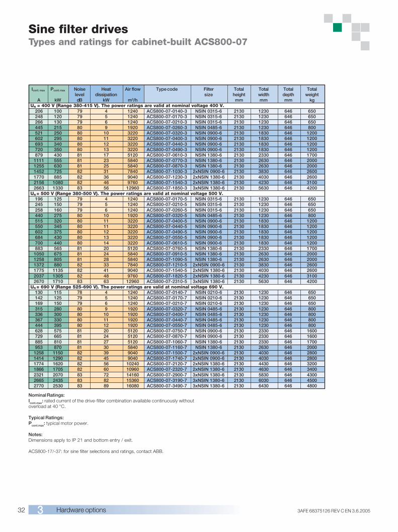
32 3AFE 68375126 REV C EN 3.6.2005Hardware options
Sine filter drivesTypes and ratings for cabinet-built ACS800-07
Icont. max Pcont. max Noise Heat Air flow Type code Filter Total Total Total Totallevel dissipation size height width depth weight
A kW dB kW m3/h mm mm mm kgUN = 400 V (Range 380-415 V). The power ratings are valid at nominal voltage 400 V.
206 100 79 4 1240 ACS800-07-0140-3 NSIN 0315-6 2130 1230 646 650248 120 79 5 1240 ACS800-07-0170-3 NSIN 0315-6 2130 1230 646 650266 130 79 6 1240 ACS800-07-0210-3 NSIN 0315-6 2130 1230 646 650445 215 80 9 1920 ACS800-07-0260-3 NSIN 0485-6 2130 1230 646 800521 250 80 10 3220 ACS800-07-0320-3 NSIN 0900-6 2130 1830 646 1200602 295 80 11 3220 ACS800-07-0400-3 NSIN 0900-6 2130 1830 646 1200693 340 80 12 3220 ACS800-07-0440-3 NSIN 0900-6 2130 1830 646 1200720 350 80 13 3220 ACS800-07-0490-3 NSIN 0900-6 2130 1830 646 1200879 430 81 17 5120 ACS800-07-0610-3 NSIN 1380-6 2130 2330 646 1700
1111 555 81 23 5840 ACS800-07-0770-3 NSIN 1380-6 2130 2630 646 20001255 630 81 25 5840 ACS800-07-0870-3 NSIN 1380-6 2130 2630 646 20001452 725 82 31 7840 ACS800-07-1030-3 2xNSIN 0900-6 2130 3830 646 26001770 885 82 36 9040 ACS800-07-1230-3 2xNSIN 1380-6 2130 4030 646 26002156 1080 82 46 9760 ACS800-07-1540-3 2xNSIN 1380-6 2130 4230 646 31002663 1330 83 56 12960 ACS800-07-1850-3 3xNSIN 1380-6 2130 5630 646 4200
UN = 500 V (Range 380-500 V). The power ratings are valid at nominal voltage 500 V.196 125 79 4 1240 ACS800-07-0170-5 NSIN 0315-6 2130 1230 646 650245 150 79 5 1240 ACS800-07-0210-5 NSIN 0315-6 2130 1230 646 650258 160 79 6 1240 ACS800-07-0260-5 NSIN 0315-6 2130 1230 646 650440 275 80 10 1920 ACS800-07-0320-5 NSIN 0485-6 2130 1230 646 800515 320 80 11 3220 ACS800-07-0400-5 NSIN 0900-6 2130 1830 646 1200550 345 80 11 3220 ACS800-07-0440-5 NSIN 0900-6 2130 1830 646 1200602 375 80 12 3220 ACS800-07-0490-5 NSIN 0900-6 2130 1830 646 1200684 430 80 13 3220 ACS800-07-0550-5 NSIN 0900-6 2130 1830 646 1200700 440 80 14 3220 ACS800-07-0610-5 NSIN 0900-6 2130 1830 646 1200883 565 81 20 5120 ACS800-07-0760-5 NSIN 1380-6 2130 2330 646 1700
1050 675 81 24 5840 ACS800-07-0910-5 NSIN 1380-6 2130 2630 646 20001258 805 81 28 5840 ACS800-07-1090-5 NSIN 1380-6 2130 2630 646 20001372 880 82 33 7840 ACS800-07-1210-5 2xNSIN 0900-6 2130 3830 646 26001775 1135 82 41 9040 ACS800-07-1540-5 2xNSIN 1380-6 2130 4030 646 26002037 1305 82 48 9760 ACS800-07-1820-5 2xNSIN 1380-6 2130 4230 646 31002670 1710 83 63 12960 ACS800-07-2310-5 3xNSIN 1380-6 2130 5630 646 4200
UN = 690 V (Range 525-690 V). The power ratings are valid at nominal voltage 690 V.130 115 78 4 1240 ACS800-07-0140-7 NSIN 0210-6 2130 1230 646 650142 125 79 5 1240 ACS800-07-0170-7 NSIN 0210-6 2130 1230 646 650169 150 79 6 1240 ACS800-07-0210-7 NSIN 0210-6 2130 1230 646 650315 280 80 9 1920 ACS800-07-0320-7 NSIN 0485-6 2130 1230 646 800336 300 80 10 1920 ACS800-07-0400-7 NSIN 0485-6 2130 1230 646 800367 330 80 11 1920 ACS800-07-0440-7 NSIN 0485-6 2130 1230 646 800444 395 80 12 1920 ACS800-07-0550-7 NSIN 0485-6 2130 1230 646 800628 575 81 20 5120 ACS800-07-0750-7 NSIN 0900-6 2130 2330 646 1600729 665 81 24 5120 ACS800-07-0870-7 NSIN 0900-6 2130 2330 646 1600885 810 81 27 5120 ACS800-07-1060-7 NSIN 1380-6 2130 2330 646 1700953 870 81 30 5840 ACS800-07-1160-7 NSIN 1380-6 2130 2630 646 2000
1258 1150 82 39 9040 ACS800-07-1500-7 2xNSIN 0900-6 2130 4030 646 28001414 1290 82 45 9040 ACS800-07-1740-7 2xNSIN 0900-6 2130 4030 646 28001774 1620 82 56 10240 ACS800-07-2120-7 2xNSIN 1380-6 2130 4430 646 32001866 1705 82 60 10960 ACS800-07-2320-7 2xNSIN 1380-6 2130 4630 646 34002321 2070 83 72 14160 ACS800-07-2900-7 3xNSIN 1380-6 2130 5830 646 43002665 2435 83 82 15360 ACS800-07-3190-7 3xNSIN 1380-6 2130 6030 646 45002770 2530 83 89 16080 ACS800-07-3490-7 3xNSIN 1380-6 2130 6430 646 4800
Nominal Ratings:Icont.max: rated current of the drive-filter combination available continuously withoutoverload at 40 °C.
Typical Ratings:Pcont.max: typical motor power.
Notes:Dimensions apply to IP 21 and bottom entry / exit.
ACS800-17/-37: for sine filter selections and ratings, contact ABB.

333AFE 68375126 REV C EN 3.6.2005 Hardware options
du/dt filters
du/dt filtering suppresses inverter output voltagespikes and rapid voltage changes that stress motorinsulation. Additionally, du/dt filtering reduces capaci-tive leakage currents and high frequency emission ofthe motor cable as well as high frequency losses andbearing currents in the motor.
The need for du/dt filtering depends on the motorinsulation. For informatioDt=0.3 µs,n on the construc-
Motor type Nominal mains Motor insulation requirementvoltage (UN )
ABB M2 and UN ≤ 500 V Standard insulation system.M3 motors 500 V < UN ≤ 600 V Standard insulation system in conjunction with du/dt filtering or reinforced insulation.
600 V < UN ≤ 690 V Reinforced insulation system in conjunction with du/dt filtering.ABB form-wound 380 V < UN ≤ 690 V Standard insulation system.HXR and AM motorsABB random-wound 380 V < UN ≤ 690 V Check motor insulation system with the motor manufacturer.HXR and AM motors du/dt filtering with voltages over 500 V.Non-ABB UN ≤ 420 V Insulation system must withstand ÛLL=1300 V.Random-wound and 420 V < UN ≤ 500 V If the insulation system withstands ÛLL=1600 V and ∆t=0.2 µs, du/dt filtering is notForm-wound required. With du/dt filtering, the insulation system must withstand ÛLL=1300 V.
500 V < UN ≤ 600 V If the insulation system withstands ÛLL=1800 V, du/dt filtering is not required.With du/dt filtering, the insulation system must withstand ÛLL=1600 V.
600 V < UN ≤ 690 V If the motor insulation system withstands ÛLL=2000 V and ∆t=0.3 µs,du/dt filtering is not required. With du/dt filtering, the insulation system mustwithstands ÛLL=1800 V
ExplanationNominal mains voltage.Peak line to line voltage at motor terminals.Rise time, i.e. interval during which line to line voltage at motor terminals changes from 10% to 90% offull voltage range.
Filter selection table for ACS800
tion of the motor insulation, consult the manufacturer.If the motor does not fulfil the following requirements,the lifetime of the motor might decrease.
Insulated N-end (non-driven end) bearings and / orcommon mode filters are also required for motorbearing currents with motors bigger than 100 kW. Formore information please see the ACS800 hardwaremanuals.
SymbolUN
Û LL
∆t
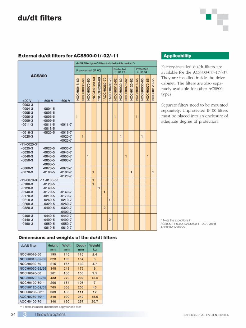
34 3AFE 68375126 REV C EN 3.6.2005Hardware options
du/dt filters
Dimensions and weights of the du/dt filters
Applicability
Factory-installed du/dt filters areavailable for the ACS800-07/-17/-37.They are installed inside the drivecabinet. The filters are also sepa-rately available for other ACS800types.
Separate filters need to be mountedseparately. Unprotected IP 00 filtersmust be placed into an enclosure ofadequate degree of protection.
Heightmm
Widthmm
Depthmm
Weightkg
du/dt filter
** 3 filters included, dimensions apply for one filter.
NOCH0016-60 195 140 115 2.4
NOCH0016-62/65 323 199 154 6
NOCH0030-60 215 165 130 4.7
NOCH0030-62/65 348 249 172 9
NOCH0070-60 261 180 150 9.5
NOCH0070-62/65 433 279 202 15.5
NOCH0120-60** 200 154 106 7
NOCH0120-62/65 765 308 256 45
NOCH0260-60** 383 185 111 12
AOCH0260-70** 340 190 242 15.9
AOCH0400-70** 340 190 257 20.7
External du/dt filters for ACS800-01/-02/-11du/dt filter type (3 filters included in kits marked *)
ACS800
400 V 500 V 690 V-0003-3-0004-3 -0004-5-0005-3 -0005-5-0006-3 -0006-5 1 1 1-0009-3 -0009-5-0011-3 -0011-5 -0011-7
-0016-5-0016-3 -0020-5 -0016-7-0020-3 -0020-7 1 1 1
-0025-7-11-0020-3*)
-0025-3 -0025-5 -0030-7-0030-3 -0030-5 -0040-7-0040-3 -0040-5 -0050-7 1 1 1-0050-3 -0050-5 -0060-7
-0060-5-0060-3 -0070-5 -0070-7-0070-3 -0100-5 -0100-7 1 1 1
-0120-7-11-0070-3*) -11-0100-5*) 1-0100-3 -0120-5 1-0120-3 -0140-5 1-0140-3 -0170-5 -0140-7 1-0170-3 -0210-5 -0170-7-0210-3 -0260-5 -0210-7 1-0260-3 -0320-5 -0260-7-0320-3 -0400-5 -0320-7 2
-0400-7-0400-3 -0440-5 -0440-7-0440-3 -0490-5 -0490-7 2-0490-3 -0550-5 -0550-7
-0610-5 -0610-7
NO
CH
0016
-60
NO
CH
0030
-60
NO
CH
0070
-60
*NO
CH
0120
-60
*NO
CH
0260
-60
*AO
CH
0260
-70
*AO
CH
0400
-70
NO
CH
0016
-62
NO
CH
0030
-62
NO
CH
0070
-62
NO
CH
0120
-62
NO
CH
0016
-65
NO
CH
0030
-65
NO
CH
0070
-65
NO
CH
0120
-65
Protectedto IP 22
Protectedto IP 54
Unprotected (IP 00)
*) Note the exceptions inACS800-11-0020-3, ACS800-11-0070-3 andACS800-11-0100-5.
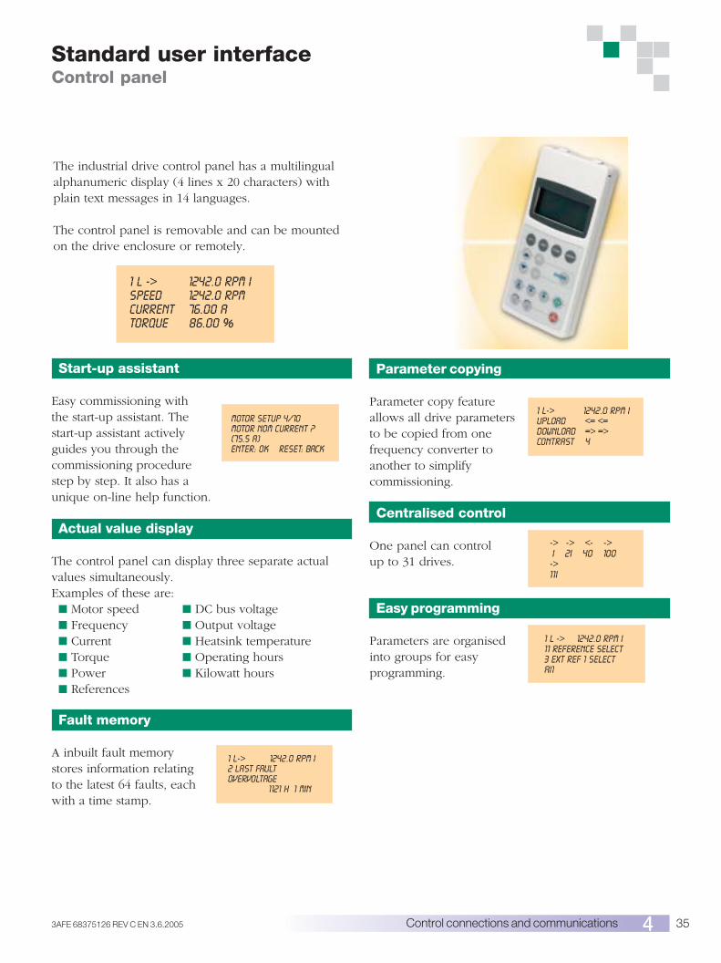
353AFE 68375126 REV C EN 3.6.2005 Control connections and communications
The industrial drive control panel has a multilingualalphanumeric display (4 lines x 20 characters) withplain text messages in 14 languages.
The control panel is removable and can be mountedon the drive enclosure or remotely.
Start-up assistant
Easy commissioning withthe start-up assistant. Thestart-up assistant activelyguides you through thecommissioning procedurestep by step. It also has aunique on-line help function.
Actual value display
The control panel can display three separate actualvalues simultaneously.Examples of these are:
■ Motor speed ■ DC bus voltage■ Frequency ■ Output voltage■ Current ■ Heatsink temperature■ Torque ■ Operating hours■ Power ■ Kilowatt hours■ References
Fault memory
A inbuilt fault memorystores information relatingto the latest 64 faults, eachwith a time stamp.
Parameter copying
Parameter copy featureallows all drive parametersto be copied from onefrequency converter toanother to simplifycommissioning.
Centralised control
One panel can controlup to 31 drives.
Easy programming
Parameters are organisedinto groups for easyprogramming.
Standard user interfaceControl panel

36 3AFE 68375126 REV C EN 3.6.2005Control connections and communications
Analog and digital I/O channels are used for differentfunctions such as control, monitoring and measurementpurposes (e.g. motor temperature). In addition, op-tional I/O extension modules are available providingadditional analog or digital I/O connections.
Standard user interfaceStandard I/O
Standard I/O on RMIO-01 Board
■ 3 analog inputs: differential, common modevoltage ±15 V, galvanically isolated as a group.■ One ±0(2)...10 V, resolution 12 bit■ Two 0(4)...20 mA, resolution 11 bit
■ 2 analog outputs:■ 0(4)...20 mA, resolution 10 bit
■ 7 digital inputs: galvanically isolated as a group(can be split in two groups)■ Input voltage 24 V DC■ Filtering (HW) time 1 ms
■ 3 digital (relay) outputs:■ Changeover contact■ 24 V DC or 115/230 V AC■ Max. continious current 2 A
■ Reference voltage output:■ ±10 V ±0.5%, max. 10 mA
■ Auxiliary power supply output:■ +24 V ±10%, max. 250 mA
Below are the standard drive control I/O of the ABBindustrial drive with Factory Macro. For other ACS800application macros the functions may be different.
Reference voltage -10 VDC,
RL > 1 kohm
Reference voltage 10 VDC,RL > 1 kohm
Speed reference 0(2) ... 10 V, Rin >200 kohm
By default, not in use. 0(4) ... 20 mA,Rin = 100 ohm
By default, not in use. 0(4) ... 20 mA,Rin = 100 ohm
Motor speed 0(4)...20 mA = 0...motornom. speed, RL < 700 ohm
Output current 0(4)...20 mA = 0...motornom. current, RL < 700 ohm
Stop/StartForward/Reverse
By default, not in use.
Acceleration & deceleration selectConstant speed select
Constant speed select
+24 V DC max. 100 mA
Digital groundDigital ground
Start interlock (0 = stop)Power supply
Auxiliary power supply output, non-isolated,24 V DC 250 mA
Relay output 1: ready
Relay output 2: running
Relay output 3: fault (-1)
^
^
VREF-
AGND
VREF+
AGND
AI1+
AI1-
AI2+
AI2-
AI3+
AI3-
AO1+
AO1-
AO2+
AO2-
DI1
DI2
DI3
DI4
DI5
DI6
+24VD
+24VD
DGND1
DGND2
DIIL
+24V
GND
RO11
RO12
RO13
RO21
RO22
RO23
RO31
RO32
RO33
X20
1
2
X21
1
2
3
4
5
6
7
8
9
10
11
12
X22
1
2
3
4
5
6
7
8
9
10
11
X23
1
2
X25
1
2
3
X26
1
2
3
X27
1
2
3
A
rpm

373AFE 68375126 REV C EN 3.6.2005 Control connections and communications
OptionsOptional I/O
Optional I/O
Analog I/O extension module RAIO-01 (+L500)■ 2 analog inputs: galvanically isolated from 24 V
supply and ground■ ±0(2)...10 V, 0(4)... 20 mA or ±0...2 V, resolution
12 bits■ 2 analog outputs: galvanically isolated from 24 V
supply and ground■ 0(4)...20 mA, resolution 12 bit
Digital I/O extension module RDIO-01 (+L501)■ 3 digital inputs: individually galvanically isolated
■ Signal level 24 to 250 V or 115/230 V AC■ 2 relay (digital) outputs:
■ Switchover contact■ 24 V or 115/230 V AC■ Max. 2 A
Pulse encoder interface module RTAC-01 (+L502)■ 1 incremental encoder input:
■ Channels A, B and Z (zero pulse)■ Signal level and power supply for the encoder is
24 or 15 V■ Single ended or differential inputs■ Maximum input frequency 200 kHz
Standard I/O can be extended by using analog anddigital extension modules or pulse encoder interfacemodules which are mounted in the slots on theASC800 control board. The control board has twoslots available for extension modules. More extension
modules can be added with the I/O extension adapterwhich has three slots. The available number andcombination of I/O's depends on the control softwareused. The standard application software supports2 analog and 2 digital extension modules.
I/O extension adapter AIMA-01
■ Three slots for I/O extension modules■ Connection to the ACS800 control board through
optic link■ Dimensions: 78 × 325 × 28 mm■ Mounting: onto 35 × 7.5 mm DIN rail■ External power supply connection■ Supply voltage: 24 V DC ±10%■ Current consumption: depends on connected I/O
extension modules

38 3AFE 68375126 REV C EN 3.6.2005Control connections and communications
ABB industrial drives have connectivity to majorautomation systems. This is achieved with a dedicatedgateway concept between the fieldbus systems andABB drives.
The fieldbus gateway module can easily be mountedinside the drive. Because of the wide range of fieldbusgateways, your choice of automation system is indepen-dent of your decision to use first-class ABB AC drives.
Manufacturing flexibility
Drive controlThe drive control word (16 bit) provides a wide varietyof functions from start, stop and reset to ramp genera-tor control. Typical setpoint values such as speed,torque and position can be transmitted to the drivewith 15 bit accuracy.
Drive monitoringA set of drive parameters and/or actual signals, such astorque, speed, position, current etc., can be selectedfor cyclic data transfer providing fast data for operatorsand the manufacturing process.
Drive diagnosticsAccurate and reliable diagnostic information can beobtained via the alarm, limit and fault words, reducingthe drive downtime and therefore also the downtimeof the manufacturing process.
Drive parameter handlingTotal integration of the drives in the production pro-cess is achieved by single parameter read/write up tocomplete parameter set-up or download.
Reduced installation and engineering effort
CablingSubstituting the large amount of conventional drivecontrol cabling with a single twisted pair reduces costsand increases system reliability.
DesignThe use of fieldbus control reduces engineering timeat installation due to the modular structure of thehardware and software.
Commissioning and assemblyThe modular machine configuration allows pre-com-missioning of single machine sections and provideseasy and fast assembly of the complete installation.
Currently available gateways
OptionsFieldbus control
Fieldbus Protocol Device profile Baud rate
PROFIBUS DP, DPV1 PROFIdrive 9.6 kbit/s - 12 Mbit/s(+K454) ABB Drives *)DeviceNet - AC/DC drive 125 kbit/s - 500 kbit/s(+K451) ABB Drives *)CANopen - Drives and motion control 10 kbit/s - 1 Mbit/s(+K457) ABB Drives *)ControlNet - AC/DC drive 5 Mbit/s(+K462) ABB Drives *)Modbus RTU ABB Drives *) 600 bit/s - 19.2 kbit/s(+K458)Ethernet Modbus/TCP ABB Drives *) 10 Mbit/s / 100 Mbit/s(+K464)InterBUS-S I/O, PCP ABB Drives *) 500 kbit/s(+K453)LONWORKS® LONTALK® Variable speed motor(+K452) drive 78 kbit/s
*) Vendor specific profile

393AFE 68375126 REV C EN 3.6.2005 Control connections and communications
OptionsRemote monitoring and diagnostics tool
Browser-based, user-friendly
The intelligent ethernet NETA-01 module gives simpleaccess to the drive via the internet, communicating viaa standard web browser. The user can set up a virtualmonitoring room wherever there is a PC with aninternet connection or via a simple dial-up modemconnection. This enables remote monitoring, configu-ration, diagnostics and, when needed, control. Thedrive can also provide process related information,such as load level, run time, energy consumption andI/O data, the bearing temperature of the driven ma-chine, for instance.
This opens up new possibilities for the monitoring andmaintenance of unmanned applications across a rangeof industries, for instance water, wind power, buildingservices and oil & gas, as well as any applicationwhere the user needs access to the drives from morethan one location. It also provides an opportunity forOEMs and system integrators to support their installedbase globally.
No PC needed at local end
The intelligent ethernet module has an embeddedserver with the necessary software for the user inter-face, communication and data storage. This givesease of access, realtime information and the possibil-ity for two-way communication with the drive,enabling immediate response and actions, saving timeand money. This is possible without using a PC at thelocal end, as required by other remote solutions.
Powerful and versatile
Up to nine drives can be connected to the intelligentethernet module via fiber optic links. It is available asan option for new drives, as well as an upgrade forexisting systems. Access to the module is secured byuser ID and passwords.
It connects to the drive with fiber optic cables. Thesize of the module is 93 (h) x 35 (w) x 76.5 (d) mm.
The web page of the module is opened like any otherweb address. The home page shows a general over-view of the system with traffic lights and actionbuttons to guide the user through the different sections.
Features
■ Virtual monitoring room for■ Monitoring■ Configuration of parameters■ Diagnostics■ Control, if needed
■ Browser-based access via■ Intra-/extra-/internet or■ Simple dial-up modem connection
■ No PC needed at the local end■ Can be used as a Modbus/TCP bridge for process
control
40 3AFE 68375126 REV C EN 3.6.2005Application software and programming
Standard application software
Standard application software
Based on Direct Torque Control technology, theACS800 offers highly advanced features as standard.The ACS800 standard application software providessolutions to virtually all AC drives applications.
Adaptive programming
In addition to parameters, industrial drives have thepossibility for function block programming as standard.Adaptive programming with 15 programmable functionblocks makes it possible to replace e.g. relays or evena PLC in some applications. Adaptive programmingcan be done either by standard control panel orDriveAP, a user-friendly PC tool.
The standard application macros
The ACS800 features inbuilt, pre-programmed applica-tion macros for configuration of such parameters asinputs, outputs and signal processing.■ FACTORY SETTINGS for basic industrial applications■ HAND/AUTO CONTROL for local and remote
operation■ PID CONTROL for closed loop processes■ SEQUENTIAL CONTROL for repetitive cycles■ TORQUE CONTROL for processes
where torque control is required■ USER MACRO 1 & 2 for user’s own parameter
settings
Software features
A complete set of standard software features offerspremium functionality and flexibility.■ Accurate speed control■ Accurate torque control without speed feedback■ Adaptive programming■ Automatic reset■ Automatic start■ Constant speeds■ Controlled torque at zero speed■ DC hold■ DC magnetizing■ Diagnostics
■ Flux braking■ Flux optimization■ IR compensation■ Master/follower control■ Mechanical brake control■ Motor identification■ Parameter lock■ Power loss ride-through■ Process PID control■ Programmable I/O■ Scalar control■ Speed controller tuning■ Start-up assistant■ Support for sine filter in the drive output■ Trim function■ User-selectable acceleration and deceleration ramps■ User adjustable load supervision/limitation
Pre-programmed protection functions
A wide range of features provides protection for thedrive, motor and the process.■ Ambient temperature■ DC overvoltage■ DC undervoltage■ Drive temperature■ Input phase loss■ Overcurrent■ Power limits■ Short circuit
Programmable protection functions
■ Adjustable power limits■ Control signal supervision■ Critical frequencies lock-out■ Current and torque limits■ Earth fault protection■ External fault■ Motor phase loss■ Motor stall protection■ Motor thermal protection■ Motor underload protection■ Panel loss
413AFE 68375126 REV C EN 3.6.2005 Application software and programming
ABB provides a set of ready-made control solutions forspecific industrial drive applications. Such softwareadds application-dedicated features and protectionwithout an external PLC - improving productivity andreducing costs.
Main advantages of ABB’s control solutions
■ Application-dedicated features■ Improved production■ No external PLC■ User-friendly■ Easy to use■ Energy savings■ Smooth power loss ride-through■ Reduced costs■ Adaptive protection
Multiblock programming
The multiblock programming application has beenspecially designed for system integrators and localengineering because of its flexibility, easy programming,large number of I/O, master-follower link and fieldbusinterfaces. Integrated into the drive control board areover 200 function blocks on 3 time levels: 20 ms, 100 msand 500 ms. These benefits mean that it is not alwaysnecessary to have separate PLC for drive and processcontrol.
Extended I/OAn analog and digital I/O extension is typically installedon the AIMA-01 I/O extension adapters. Three exten-sion modules can be installed on each I/O extensionadapter and an optical link connects the I/O extensionadapters to the drive control board. The maximumnumber of I/O connections is 62.
ProgrammingFunction blocks are easy to program using the DriveAP2 PC tool. For example, there are PROFIBUS fieldbusblocks available to help users to understand the blockprogram connections between the drive and Profibusmaster. Block program information, as well as textcomments, symbolic names of block outputs and page
Optional application softwareControl solutions for different applications
header information is saved in the flash memory of thecontrol board of the drive.
Pump control
Intelligent pump control software is a combination oftraditional PFC which is specially designed for multi-motor pumping (or compressor, etc.) stations. Whiledirectly controlling one motor, the drive is able to startadditional, direct-on-line motors whenever a highercapacity is needed.
Multipump functionAdditional features such as the multipump function aredesigned for pumping stations that consist of multiplepumps, each controlled by a separate drive. The drivescan be connected so that in the case of pump failureor maintenance action on one drive, the remainingdrives continue operation - having 100% redundancy.There is an autochange function to alternate betweenthe pumps so all pumps have an equal duty time.
Level control functionThe liquid level of a container can be used as aprocess variable for a pumping station either filling oremptying the container when the level control functionis activated. Three drives can be used in a master/follower configuration.
Flow calculationThe flow calculation contains a function that enablesreasonably accurate calculation of flow without theinstallation of a separate flow meter.
Anti-jam functionThe anti-jam function can be used for preventingsolids from building up on pump impellers. The anti-jam procedure consists of a programmable sequenceof forward and reverse runs of the pump, effectivelyshaking off any residue on the impeller.
Adaptive programmingAdaptive programming using 15 function blocks ispossible with the pump control. The adaptive pro-gramming makes customizing possible without theneed for a special programming tool or language.

42 3AFE 68375126 REV C EN 3.6.2005Application software and programming
Centrifuge control
Practical programmable sequences for conventionalcentrifuges. Integrated decanter control for the accu-rate speed difference control of two shafts, wheredirect communication via the fiber optic link betweenbowl and scroll is used.
Crane drive control
Crane drive control with optimal operational safetyand performance built into the drive.■ Easy installation and start-up reduces the total
project costs■ Ready to use with proven crane functionality■ Accurate and fast response increases the
operational productivity■ Multiple drives can be synchronized with internal
optic link, reducing the need for separate control-lers. Everything needed is inbuilt
■ Smooth crane operation reduces maintenance costs■ Available as single drive or multi-drive with
dynamic and regenerative braking
Standard ready-to-use crane solution.
Extruder control
High starting torque, accurate speed/torque controlwithout an encoder for demanding extruder applica-tions. The extruder screw and other delicatemechanical parts can be protected against overload.
Master/follower control
Reliable control via the fiber optic link of severaldrives when they are controlled by one master. Thisis needed e.g. if the motor shafts are coupled to-gether. The master/follower function enables the loadto be evenly distributed between the drives.
Spinning control & traverse control
Spinning control and traverse control make a perfectpair for the precise control of spinning and traversedrives in textile machines.
System application
This application software is targeted for multi-motormachines producing or processing metal, paper, plas-tics, textile, rubber and cement, and for numerousother demanding applications. The basic control modesare speed control and torque control. Fast communica-tion with the overriding controller can exchangeoperative data (references, command words) andsupport data (configuration data, diagnostics). Propri-etary (DDCS, Drive bus) and generic (PROFIBUS,InterBUS-S, DeviceNet) protocols enable linking ofdrives to controllers, PLC and PCs.
Main features and benefits:■ Motor fan control with diagnostics■ Soft changeover between the speed and torque
control modes■ Speed control gain as a function of output on low
speed or as a function of motor frequency■ Thermal model for motor cable protection■ Torsional oscillation damping function to damp
mechanical oscillations.
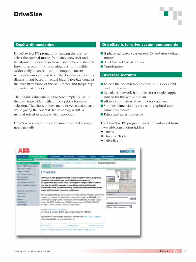
433AFE 68375126 REV C EN 3.6.2005 PC tools
Quality dimensioning
DriveSize is a PC program for helping the user toselect the optimal motor, frequency converter andtransformer, especially in those cases where a straight-forward selection from a catalogue is not possible.Additionally it can be used to compute currents,network harmonics and to create documents about thedimensioning based on actual load. DriveSize containsthe current versions of the ABB motor and frequencyconverter catalogues.
The default values make DriveSize simple to use, butthe user is provided with ample options for driveselection. The shortcut keys make drive selection easywhile giving the optimal dimensioning result. Amanual selection mode is also supported.
DriveSize is currently used by more than 1,000 engi-neers globally.
DriveSize
DriveSize is for drive system components
■ 3-phase standard, customized, Ex and user definedmotors
■ ABB low voltage AC drives■ Transformers
DriveSize features
■ Selects the optimal motor, drive unit, supply unitand transformer
■ Calculates network harmonics for a single supplyunit or for the whole system
■ Allows importation of own motor database■ Supplies dimensioning results in graphical and
numerical format■ Prints and saves the results
The DriveSize PC program can be downloaded fromwww.abb.com/motors&drives➡ Drives➡ Drive PC Tools➡ DriveSize

44 3AFE 68375126 REV C EN 3.6.2005PC tools
Programming tool
DriveAP is a PC software tool for creating, document-ing, editing and downloading adaptive programs andmultiblock programming programs. DriveAP 1.1supports adaptive programming, whereas DriveAP 2supports both adaptive programming and multiblockprogramming applications. The adaptive programmingcontains 15 function blocks and is available in astandard application. The multiblock programmingapplication contains over 200 function blocks, andalso includes PROFIBUS fieldbus and drive I/O blocks.DriveAP offers a clear and easy way to develop, testand document these programs with a PC.
It is a user-friendly tool for modifying function blocksand their connections. No special programming skillsare required, a basic knowledge about block program-ming is enough. DriveAP supports IEC61131.
The adaptive programs are easy to document as hardcopies or store as PC files. The multiblock program-ming with all related information is saved directly tothe drive.
Upload or download
Both program types can be uploaded from connecteddrives and displayed graphically on a PC screen forservice or documentation purposes, for example.
The adaptive programs and multiblock programmingprograms made off-line can be downloaded to any ofthe connected drives that support correspondingprograms.
Three operating modes
■ Stand-alone mode - DriveAP is not connected to adrive. The adaptive programming and multiblockprogramming can be carried out in the office, forexample, and later downloaded to a drive.
■ Off-line mode - DriveAP is connected to a drive. Theadaptive programming and multiblock programmingcan be carried out in batch mode.
■ On-line mode - DriveAP is connected to a drive.Changes to the adaptive programs and multiblockprograms are written immediately to the drive andactual values are shown on the screen in real-time.
DriveAP features
■ Easy-to-use tool, no special skills required■ Create and download new programs■ Document programs■ Upload existing programs from the drive■ Operating modes
■ Stand-alone■ Off-Line■ On-Line
DriveAP
DriveAP with adaptive program of standard application. DriveAP with multiblock programming application.
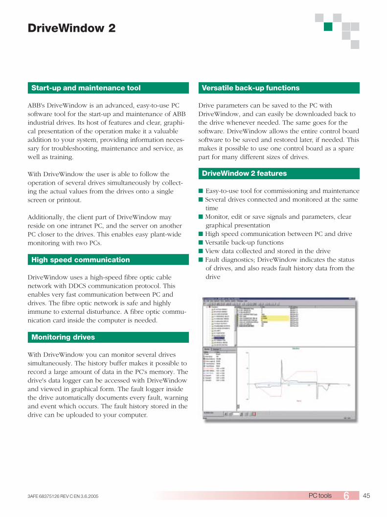
453AFE 68375126 REV C EN 3.6.2005 PC tools
Start-up and maintenance tool
ABB's DriveWindow is an advanced, easy-to-use PCsoftware tool for the start-up and maintenance of ABBindustrial drives. Its host of features and clear, graphi-cal presentation of the operation make it a valuableaddition to your system, providing information neces-sary for troubleshooting, maintenance and service, aswell as training.
With DriveWindow the user is able to follow theoperation of several drives simultaneously by collect-ing the actual values from the drives onto a singlescreen or printout.
Additionally, the client part of DriveWindow mayreside on one intranet PC, and the server on anotherPC closer to the drives. This enables easy plant-widemonitoring with two PCs.
High speed communication
DriveWindow uses a high-speed fibre optic cablenetwork with DDCS communication protocol. Thisenables very fast communication between PC anddrives. The fibre optic network is safe and highlyimmune to external disturbance. A fibre optic commu-nication card inside the computer is needed.
Monitoring drives
With DriveWindow you can monitor several drivessimultaneously. The history buffer makes it possible torecord a large amount of data in the PC's memory. Thedrive's data logger can be accessed with DriveWindowand viewed in graphical form. The fault logger insidethe drive automatically documents every fault, warningand event which occurs. The fault history stored in thedrive can be uploaded to your computer.
Versatile back-up functions
Drive parameters can be saved to the PC withDriveWindow, and can easily be downloaded back tothe drive whenever needed. The same goes for thesoftware. DriveWindow allows the entire control boardsoftware to be saved and restored later, if needed. Thismakes it possible to use one control board as a sparepart for many different sizes of drives.
DriveWindow 2 features
■ Easy-to-use tool for commissioning and maintenance■ Several drives connected and monitored at the same
time■ Monitor, edit or save signals and parameters, clear
graphical presentation■ High speed communication between PC and drive■ Versatile back-up functions■ View data collected and stored in the drive■ Fault diagnostics; DriveWindow indicates the status
of drives, and also reads fault history data from thedrive
DriveWindow 2

46 3AFE 68375126 REV C EN 3.6.2005PC tools
DriveWindow Light 2
Start-up and maintenance tool
DriveWindow Light 2 is an easy-to-use start-up andmaintenance tool for ACS800 drives. It supports thefollowing software: standard application, pump control,and spinning and traverse control.
DriveWindow Light uses the drive’s panel connectorfor communication, which makes communication setupvery easy.
Light software with heavy features
DriveWindow Light offers many functions in an easy-to-use package. It can be used in an offline mode,which enables parameter setting at the office evenbefore going to the actual site. The parameter browserenables viewing, editing and saving of parameters. Theparameter comparison feature makes it possible tocompare parameter values between the drive and thefile. With the parameter subset you can create yourown parameter sets. Controlling of the drive is natu-rally one of the features in DriveWindow Light.With DriveWindow Light, you can monitor up to foursignals simultaneously. This can be done in bothgraphical and numerical format. Any signal can be setto stop the monitoring from a predefined level.
Highlights
■ Viewing and setting parameters in offline mode■ Editing, saving and downloading parameters■ Comparing parameters■ Graphical and numerical signal monitoring■ Drive control
DriveWindow Light requirements
■ Windows 98/NT/2000/XP■ Free serial port from a PC■ Free control panel connector■ NPCU-01 PC connection unit
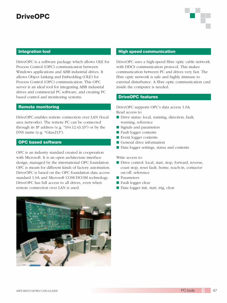
473AFE 68375126 REV C EN 3.6.2005 PC tools
Integration tool
DriveOPC is a software package which allows OLE forProcess Control (OPC) communication betweenWindows applications and ABB industrial drives. Itallows Object Linking and Embedding (OLE) forProcess Control (OPC) communication. This OPCserver is an ideal tool for integrating ABB industrialdrives and commercial PC software, and creating PCbased control and monitoring systems.
Remote monitoring
DriveOPC enables remote connection over LAN (localarea networks). The remote PC can be connectedthrough its IP address (e.g. "164.12.43.33") or by theDNS name (e.g. "Gitas213").
OPC based software
OPC is an industry standard created in cooperationwith Microsoft. It is an open architecture interfacedesign, managed by the international OPC foundation.OPC is meant for different kinds of factory automation.DriveOPC is based on the OPC foundation data accessstandard 1.0A and Microsoft COM/DCOM technology.DriveOPC has full access to all drives, even whenremote connection over LAN is used.
High speed communication
DriveOPC uses a high-speed fibre optic cable networkwith DDCS communication protocol. This makescommunication between PC and drives very fast. Thefibre optic network is safe and highly immune toexternal disturbance. A fibre optic communication cardinside the computer is needed.
DriveOPC features
DriveOPC supports OPC’s data access 1.0A.Read access to:■ Drive status: local, running, direction, fault,
warning, reference■ Signals and parameters■ Fault logger contents■ Event logger contents■ General drive information■ Data logger settings, status and contents
Write access to:■ Drive control: local, start, stop, forward, reverse,
coast stop, reset fault, home, teach-in, contactoron/off, reference
■ Parameters■ Fault logger clear■ Data logger init, start, trig, clear
DriveOPC

48 3AFE 68375126 REV C EN 3.6.20057
Summary of features and options
Summary of features and options
Power & voltage range230 V400 V500 V690 V
MountingWall mountingFree-standingTwo mounting directions:bookshelf / flat (=sideways)CablingBottom entry & exitTop entry & exitEnclosure classIP 21 (UL type 1)IP 22 (UL type 1)IP 42 (UL type 1)IP 54 (UL type 12)IP 54RIP 55 (UL type 12)DTC motor controlDTCSoftware 2)Start-up assistantAdaptive programmingOptional software optimizedfor different applications or forenhanced programmability:for more details see section"Application software andprogramming"Control panelAlphanumeric 4*20 charactercontrol panelControl connections (I/O)and communications3 pcs analog inputs,programmable, galvanicallyisolated2 pcs analog outputs,programmable7 pcs digital inputs,programmable, galvanicallyisolated - can be dividedinto two groups3 pcs relay outputs,programmableThermistor relay (1 or 2 pcs)Pt100 relaysPossibility for external controlvoltageInbuilt I/O extension andspeed feedback modules: formore details see section"Control connections andcommunications"Inbuilt adapters for severalfieldbuses: for more details seesection "Control connectionsand communications"EMC filtersEMC 1st environmentEMC 2nd environment, earthednetworks onlyEMC 2nd environment, earthedand unearthed networks
OrderingCode
H351+H353
B053B054B055B059B056
L505L506
E202
E200
E210
- 01
0.55 - 55 kW 1.1 - 110 kW1.5 - 110 kW5.5 - 110 kW
-
-
-
----
3) 3)
--
5)
-
- 02
45 - 200 kW90 - 400 kW110 - 500 kW90 - 560 kW
-
-----
3) 3)
4)
5)
-
- 07R6-R8
45 - 400 kW55 - 500 kW45 - 560 kW
-
-
-
3) 3)
5)
7)
9)
- 07nxR8i
400 - 1400 kW500 - 1900 kW500 - 2800 kW
-
-
1)
-
3) 3)
6)
-
- 17R6-R8i
45 - 400 kW55 - 500 kW90 - 450 kW
-
-
-
3) 3)
5)
8)
9)
- 11
5.5 - 45 kW11 - 90 kW15 - 110 kW
-
-
-
-----
3) 3)
--
-
- 37nxR8i
355 - 1600 kW450 -1 800 kW450 - 2800 kW
-
-
-
3) 3)
6)
- 17nxR8i
355 - 1600 kW450 -1 800 kW450 - 2500 kW
-
-
-
3) 3)
6)
- 37R6-R8i
45 - 400 kW55 - 500 kW90 - 450 kW
-
-
-
3) 3)
5)
8)
9)
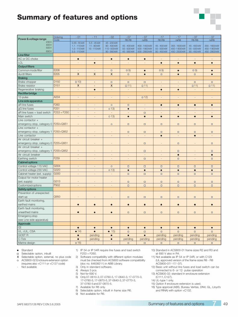
493AFE 68375126 REV C EN 3.6.2005 Summary of features and options 7
1) IP 54 or IP 54R require line fuses and load switchF253 + F260.
2) Software compatibility with different option modulesmust be checked from ACS800 software compatibility(doc no. 64638211) in ABB Library.
3) Only in standard software.4) Always 3 pcs.5) Not for 690 V.6) Only 07-0610-3, 07-0760-5, 17-0640-3, 17-0770-3,
17-0780-5, 17-0870-5, 37-0640-3, 37-0770-3,37-0780-5 and 37-0870-5.
7) Available for R6 only.8) Selectable option, inbuilt in frame size R6.9) Not available for R6.
StandardSelectable option, inbuilt
X Selectable option, external, no plus codeACS800-02 Enclosure extension option(requires also +C111 or +C127 code)
- Not available
Summary of features and options
10) Standard in ACS800-01 frame sizes R2 and R3 andat 690 V also in R4.
11) Not available as IP 54 or IP 54R, or with C129(UL approved version of the frame sizes R6 - R8ACS800-07/ -17/ -37).
12) Basic unit without line fuses and load switch can beconnected to 6- or 12- pulse operation
13) ACS800-02: standard in enclosure extension(C111, C127).
14) UL-type 1 only.15) Option if enclosure extension is used.16) Type approval (ABS, Bureau Veritas, DNV, GL, Lloyd’s
and RINA) with option +C132.
- 01
0.55 - 55 kW1.1 - 110 kW1.5 - 110 kW5.5 - 110 kW
-
-X
10)X-
-
----
-
--
-
---
---
--
-
14)
16)
- 02
45 - 200 kW90 - 400 kW
110 - 500 kW90 - 560 kW
-
X
X-
-
13)-
13)
--
-
---
13)-
--
-
15)
-
- 07R6-R8
45 - 400 kW55 - 500 kW45 - 560 kW
-
9)
11)-
-
-
-
-
---
pending
- 07nxR8i
400 - 1400 kW500 - 1900 kW500 - 2800 kW
-
11)-
12)
--
-
-
pending
-17R6-R8i
45 - 400 kW55 - 500 kW90 - 450 kW
-
9)
--
-
--
-
---
pendingpending
OrderingCode
E208E205
D150D151
A004
F260F251F253 + F260
F250+Q951
F250+Q952
F255+Q951
F255+Q952
F259
G304G320G300
G313P902
Q950
Power & voltage range230 V400 V500 V
690 V
Line filterAC or DC chokeLCLOutput filtersCommon mode filterdu/dt filtersBrakingBrake chopperBrake resistorRegenerative brakingRectifier bridge12-pulseLine side apparatusaR line fusesgG line fusesaR line fuses + load switchMain switchLine contactor +emergency stop, category 0Line contactor +emergency stop, category 1Line contactorAir circuit breaker +emergency stop, category 0Air circuit breaker +emergency stop, category 1Air circuit breakerEarthing switchCabinet optionsControl voltage 115 VACControl voltage 230 VACCabinet heater (ext. supply)Output for motor heater(ext. supply)Customized optionsSafety optionsPrevention of unexpectedstart-upEarth fault monitoring,earthed mainsEarth fault monitoring,unearthed mainsEmergency stop(see Line side apparatus)ApprovalsCEUL, cUL, CSAGOST RC-TickMarine design
- 11
5.5 - 45 kW11 - 90 kW15 - 110 kW
-
-X
--
-
----
-
--
-
---
---
--
-
pendingpending
-
- 37nxR8i
355 - 1600 kW450 -1 800 kW450 - 2800 kW
-
11)-
-
--
-
pendingpending
- 37R6-R8i
45 - 400 kW55 - 500 kW90 - 450 kW
-
9)
11)-
-
--
-
---
pendingpending
- 17nxR8i
355 - 1600 kW450 -1 800 kW450 - 2500 kW
-
--
-
--
-
pendingpending
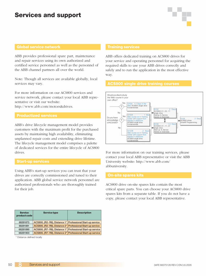
50 3AFE 68375126 REV C EN 3.6.2005Services and support8
Services and support
Global service network
ABB provides professional spare part, maintenanceand repair services using its own authorized andcertified service personnel as well as the personnel ofthe ABB channel partners all over the world.
Note: Though all services are available globally, localservices may vary.
For more information on our ACS800 services andservice network, please contact your local ABB repre-sentative or visit our website:http://www.abb.com/motors&drives.
Productized services
ABB’s drive lifecycle management model providescustomers with the maximum profit for the purchasedassets by maintaining high availability, eliminatingunplanned repair costs and extending drive lifetime.The lifecycle management model comprises a paletteof dedicated services for the entire lifecycle of ACS800drives.
Start-up services
Using ABB’s start-up services you can trust that yourdrives are correctly commissioned and tuned to theirapplication. ABB global service network personnel areauthorized professionals who are thoroughly trainedfor their job.
Training services
ABB offers dedicated training on ACS800 drives foryour service and operating personnel for acquiring therequired skills to use your ABB drives correctly andsafely and to run the application in the most effectiveway.
ACS800 single drive training courses
68281873 ACS800, (R2- R6), Distance 1* Professional Start-up service68281881 ACS800, (R2- R6), Distance 2* Professional Start-up service
68281890 ACS800, (R7- R8), Distance 1* Professional Start-up service68281903 ACS800, (R7- R8), Distance 2* Professional Start-up service
Serviceproduct code
Service type Description
* Distance defined locally
Would you like to studythe Web course in yourown office?
Do you havea knowledgeof ACS 600?
Yes
Yes
No
No
G152e 1-2 Days in theWeb ACS800 single driveFundamentals
G152A 1 DayWeb course run in TrainingCenter with support fromteacher in classroomACS800 single driveFundamentals
G152B 2 DaysWeb course run in TrainingCenter with support fromteacher in classroomACS800 single driveFundamentals
?
?
G152 2 DaysACS800-01,-02,-11single driveStartup & ServiceHands on Exercises
G156 1.5 DaysACS800-07,-17,-37single driveStart-up & ServiceHands-on Exercises
G158 2 DaysACS800 drivesDriveAP Programming
For more information on our training services, pleasecontact your local ABB representative or visit the ABBUniversity website: http://www.abb.com/abbuniversity.
On-site spares kits
ACS800 drive on-site spares kits contain the mostcritical spare parts. You can choose your ACS800 drivespares kits from a separate table. If you do not have acopy, please contact your local ABB representative.
513AFE 68375126 REV C EN 3.6.2005 Contact and web information
ABB’s worldwide presence is built on strong localcompanies working together with the local distributorand channel partner network across borders to achievea uniform level of services for all our customers. Bycombining the experience and know-how gained inlocal and global markets, we ensure that our customersin all industries can gain the full benefit from ourproducts.
For further details about all our variable speed driveproducts and services please contact your nearest ABBoffice or visit the ABB website www.abb.com/motors&drives.
Contact and web informationwww.abb.com/motors&drives
Argentina (Valentin Alsina)Tel: +54 (0)114 229 5707Fax: +54 (0)114 229 5593
Australia (Victoria)Tel: 1800 222 435Tel: +61 3 8544 0000Fax: +61 3 8544 0004
Austria (Vienna)Tel: 0800 201 009Tel: +43 1 60109-0Fax: +43 1 60109-8312
Belarus (Minsk)Tel: +375 172 236 711Tel: +375 172 239 185Fax: +375 172 239 154
Belgium (Zaventem)Tel: +32 2 718 6313Fax: +32 2 718 6664
Bolivia (La Paz)Tel: +591 2 242 3636Fax: +591 2 242 3698
Bosnia Herzegovina (Tuzla)Tel: +387 35 255 097Fax: +387 35 255 098
Brazil (Sao Paulo)Tel: 0800 149 111Tel: +55 11 3688 9282Fax: +55 11 3684 1991
Bulgaria (Sofia)Tel: +359 2 981 4533Fax: +359 2 980 0846
Canada (Montreal)Tel: +1 514 215 3006Fax: +1 514 332 0609
Chile (Santiago)Tel: +56 2 471 4391Fax: +56 2 471 4399
China (Beijing)Tel: +86 10 8456 6688Fax: +86 10 8456 7636
Colombia (Bogota)Tel: +57 1 417 8000Fax: +57 1 413 4086
Croatia (Zagreb)Tel: +385 1 600 8550Fax: +385 1 619 5111
Czech Republic (Prague)Tel: +420 234 322 360Fax: +420 234 322 310
Denmark (Skovlunde)Tel: +45 44 504 345Fax: +45 44 504 365
Estonia (Tallinn)Tel: +372 6 711 800Fax: +372 6 711 810
Finland (Helsinki)Tel: +358 10 22 11Tel: +358 10 222 1999Fax: +358 10 222 2913
France (Champagne)Tel: +33 (0)810 020 000Fax: +33 (0)472 054 041
Germany (Lampertheim)Tel: +01805 123 580Tel: +49 (0)6206 503 503Fax: +49 (0)6206 503 600
Greece (Athens)Tel: +30 210 289 1900Fax: +30 210 289 1999
Hungary (Budapest)Tel: +36 1 443 2224Fax: +36 1 443 2144
India (Bangalore)Tel: +91 80 837 0416Fax: +91 80 839 9173
Indonesia (Jakarta)Tel: +62 21 590 9955Fax: +62 21 590 0115Fax: +62 21 590 0116
Ireland (Dublin)Tel: +353 1 405 7300Fax: +353 1 405 7312
Israel (Tirat Carmel)Tel: +972 4 858 1188Fax: +972 4 858 1199
Italy (Milano)Tel: +39 02 2414 3792Fax: +39 02 2414 3979
Japan (Tokyo)Tel: +81(0)3 5784 6010Fax: +81(0)3 5784 6275
Latvia (Riga)Tel: +371 7 063 600Fax: +371 7 063 601
Lithuania (Vilnius)Tel: +370 5 273 8300Fax: +370 5 273 8333
Luxembourg (Leudelange)Tel: +352 493 116Fax: +352 492 859
Macedonia (Skopje)Tel: +389 2 118 010Fax: +389 2 118 774
Malaysia (Kuala Lumpur)Tel: +60 3 5628 4888Fax: +60 3 5631 2926
Mexico (Mexico City)Tel: +52 55 5328 1400Fax: +52 55 5328 1482/1439
The Netherlands(Rotterdam)Tel: +31 (0)10 407 8362Fax: +31 (0)10 407 8433
New Zealand (Auckland)Tel: +64 9 356 2170Fax: +64 9 357 0019
Norway (Oslo)Tel: +47 22 872 000Fax: +47 22 872 541
Peru (Lima)Tel: +51 1 561 0404Fax: +51 1 561 3040
Philippines (Metro Manila)Tel: +63 2 821 7777Fax: +63 2 823 0309Fax: +63 2 824 4637
Poland (Lodz)Tel: +48 42 299 3000Fax: +48 42 299 3340
Portugal (Amadora)Tel: +351 21 425 6239Fax: +351 21 425 6392
Romania (Bucarest)Tel: +40 21 310 4377Fax: +40 21 310 4383
Russia (Moscow)Tel: +7 095 960 22 00Fax: +7 095 913 96 96/95
Saudi-Arabia (Al Khobar)Tel: +966 (0)3 882 9394Fax: +966 (0)3 882 4603
Serbia and Montenegro(Belgrade)Tel: +381 11 324 4341Fax: +381 11 324 1623
SingaporeTel: +65 6776 5711Fax: +65 6778 0222
Slovakia (Banska Bystrica)Tel: +421 48 410 2324Fax: +421 48 410 2325
Slovenia (Ljubljana)Tel: +386 1 587 5482Fax: +386 1 587 5495
South Africa (Johannesburg)Tel: +27 11 617 2000Fax: +27 11 908 2061
South Korea (Seoul)Tel: +82 2 528 2794Fax: +82 2 528 2338
Spain (Barcelona)Tel: +34 (9)3 728 8700Fax: +34 (9)3 728 8743
Sweden (Västerås)Tel: +46 (0)21 32 90 00Fax: +46 (0)21 14 86 71
Switzerland (Zürich)Tel: +41 (0)58 586 0000Fax: +41 (0)58 586 0603
Taiwan (Taipei)Tel: +886 2 2577 6090Fax: +886 2 2577 9467Fax: +866 2 2577 9434
Thailand (Bangkok)Tel: +66 (0)2665 1000Fax: +66 (0)2665 1042
Turkey (Istanbul)Tel: +90 216 528 2200Fax +90 216 365 2944
United Kingdom(Manchester)Tel: +44 (0)161 445 5555Fax. +44 (0)161 445 6066
Uruguay (Montevideo)Tel: +598 2 707 7300Tel: +598 2 707 7466
USA (New Berlin)Tel: +1 800 752 0696Tel: +1 262 785 3200Fax: +1 262 785 0397
Venezuela (Caracas)Tel: +58 212 203 1817Fax: +58 212 237 6270

Ad
agen
cy P
iirte
k O
y #1
1958
ABB OyDrivesP. O. Box 184FI - 00381 HelsinkiFinlandTelephone +358 10 22 11Fax +358 10 22 22681Internet http://www.abb.com/motors&drives
HA
NS
AP
RIN
T/S
AL0
5_00
480/
20
05
© C
opyr
ight
200
5 A
BB
. All
right
s re
serv
ed. 3
AFE
683
7512
6 R
EV
C E
N 3
.6.2
005
Spe
cific
atio
ns s
ubje
ct to
cha
nge
with
out n
otic
e.