driving equipment with three-phase inverters and … · driving equipment with three-phase...
TRANSCRIPT
Driving equipment with three-phase inverters and asynchronous traction motors for trolleys and trams
V. Radulescu, I. Strainescu, L. Moroianu, S. Gheorghe, E. Tudor, V. Lupu, F. Bozas, A. Dascalu, G. Mitroi & D. Braslasu ICPE SAERP S.A., Romania
Abstract
The company ICPE SAERP S.A. is the main producer of electric drives for urban traction and for railway vehicles in Romania. The products of our company are subject to the last 48 years of permanent evolution, based on the semiconductor’s development and of the microprocessors control techniques. The improvement of the passenger’s comfort and the downsizing of the exploitation costs is a must for public transportation companies, relating to trolleybuses and trams. Both can be achieved by using modern electric drives (DC choppers or three-phase inverters), which can reduce power consumption and increase control of the vehicle. The main products for electric traction are: drives for traction motors of the vehicles (DC choppers for DC series motors and three-phase inverters for asynchronous and for synchronous motors) and converters for auxiliary services of the vehicles with two development directions, battery chargers (DC converters) for drive supply (24Vdc or 110Vdc) and three-phase inverters for auxiliary asynchronous motors (steering, compressor). ICPE SAERP SA has delivered 310 pcs. traction equipment with DC chopper with GTO thyristors or IGBT transistors that equip the trolleybuses from Astrabus srl Arad for the final customers RAT Bucharest, Transurb Galaţi and Ratuc Cluj – Napoca. This paper presents driving equipment with three-phase inverters for asynchronous motors for trolleys and trams that ICPE SAERP has delivered in the past three years. The paper also presents the equipment’s performances, the analysed principle for electrical power diagrams. Keywords: three-phase inverter, asynchronous traction motor, electrical vehicle.
www.witpress.com, ISSN 1743-3509 (on-line) WIT Transactions on The Built Environment, Vol 114, © 2010 WIT Press
Computers in Railways XII 561
doi:10.2495/CR100521
1 Introduction
The nominal input voltage for the driving equipment with a three-phase inverter and asynchronous traction motors is 750 Vdc or 600 Vdc, with a voltage variation of +25%...–30%, to which the atmospherically voltages are added. The nominal input voltage for the microprocessors command block is 24 Vdc with a variation of +25%...–30%. This voltage comes from the battery on the urban vehicle (tram, subway frame, trolley). The driving equipment is conceived so that it can function in harsh conditions: high mechanical vibrations, a temperature domain of –40....+ 55oC etc. This equipment has a LC input filter, a three-phase power inverter and asynchronous traction motor. The three-phase inverter design is based on high voltage IGBT transistors. The existing control software allow four main functions:
o Control – by reading the current state of the vehicle’s electrical driving system and the commands given by the system [3];
o Adjustment – through the commands sent to the three-phase inverter – INV3 – that actions two (for trams) or one asynchronous traction motor (for trolley). During the traction electrical breaking with energy saving regimes, the couple is always adjusted. In case of electrical breaking, the voltage limitation from the filter is ensured by connecting the dynamic break, so that the total break couple would be the one asked by the driver from the. The adjustment block assures also the anti-slide protection when starting the vehicle and anti-blocking when the vehicle uses electrical breaking.
o Communication – on an internal level, between the Master and Slave control cards but also with an external computer, for the diagnosis;
o Diagnosis – by collecting and memorizing the significant data for the status of the whole system; supplementary, an alphanumeric display with 4 lines of 20 characters is available, that reflects the current status of the whole system.
2 The ICPE SAERP equipment for the driving of the tram or light subway wagon
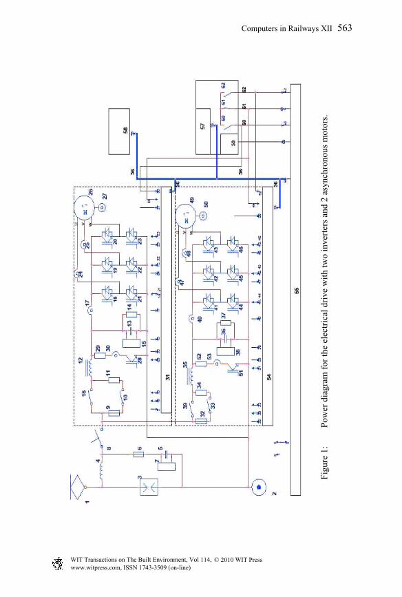
The electrical power diagram of the driving equipment for the tram with two motor bogie, each bogie being equipped with two three-phase asynchronous traction motor and two inverters with IGBT transistors, each inverter supplying one asyncronous motor with variable voltage and frequency. This is presented in the Figure 1. The input DC voltage, collected by a pantograph 1 (pozitive phase) from the line, is applied to a surcharge discharger 3 and respectively through an inductance 4, a radio parasites filter 5 and after that a main contactor 8. In parallel on the capacitor 5 a voltage transducer 7 is connected, to measure the contact line voltage.
www.witpress.com, ISSN 1743-3509 (on-line) WIT Transactions on The Built Environment, Vol 114, © 2010 WIT Press
562 Computers in Railways XII
Fig
ure
1:
Pow
er d
iagr
am f
or th
e el
ectr
ical
dri
ve w
ith
two
inve
rter
s an
d 2
asyn
chro
nous
mot
ors.
www.witpress.com, ISSN 1743-3509 (on-line) WIT Transactions on The Built Environment, Vol 114, © 2010 WIT Press
Computers in Railways XII 563
By connecting the main contactor, it charges the two three-phase inverters (transistors 18-23 and 41-46) for the driving of the two traction motors 26 and 49 mounted on the bogies. To limit the initial current shock to the capacitive filter 13 and 36, we introduced two resistors 11 and 34, that are short-circuited by the contactors 10 and 33 after a certain time. The first three-phase inverter through two phase current transducers 24 and 25 supplies the three-phase asynchronous motor 26, that has a overspeed and position transducer 27, that measures the motors speed and it’s rotation direction. With the help of a transistor 28 and of a rheostatic breaking resistor we can control the voltage on the supplying line during the electrical braking operation. The inverter gives the command to supply the traction motor with variable voltage and frequency, following the statoric field of the motor, by an inverter command block 31, made with a master microprocessor and one or more slave microprocessors. The inverter command block 31 assures the traction and energy saving electrical breaking regimes and when the network does not receive all breaking energy, the start of the rheostatic break command is given, as a difference between the asked breaking effort and the one with energy saving. To action the traction motor on the second bogie we use a similar scheme as presented, for the driving of the first bogie, using elements 32...54. To action the whole tram, we use a general command block 55, with a master microprocessor and one or more slave microprocessors, receiving a series of information from all the blocks and the traction elements: through a data highway 56 the data and information is transmitted between the main command block 55 and the inverter command blocks 31 and 54. Also through this highway the data needed for an intelligent display block 57 (placed on the board of the vehicle) and for a laptop computer 58 (for the diagnosis data extraction from the command blocks) are transmitted. With the help of a tram command controller 59, placed on the vehicle’s board, the driver commands the run regimes (forward and backwards), normal breaking, emergency breaking and stop breaking, and also starting acceleration and breaking deceleration, this data are transmitted to the main command block through a data highway 60. By pressing the 61 and 62 buttons on the board, the driver can disconnect the first or second inverter, if one of them malfunctions; in this way the driver can ensure the safe return to the garage. With the help of an emergency breaking device 63, we can ensure the emergency breaking at full value when it’s needed.
3 ICPE SAERP’s equipment for trolley electrical drive
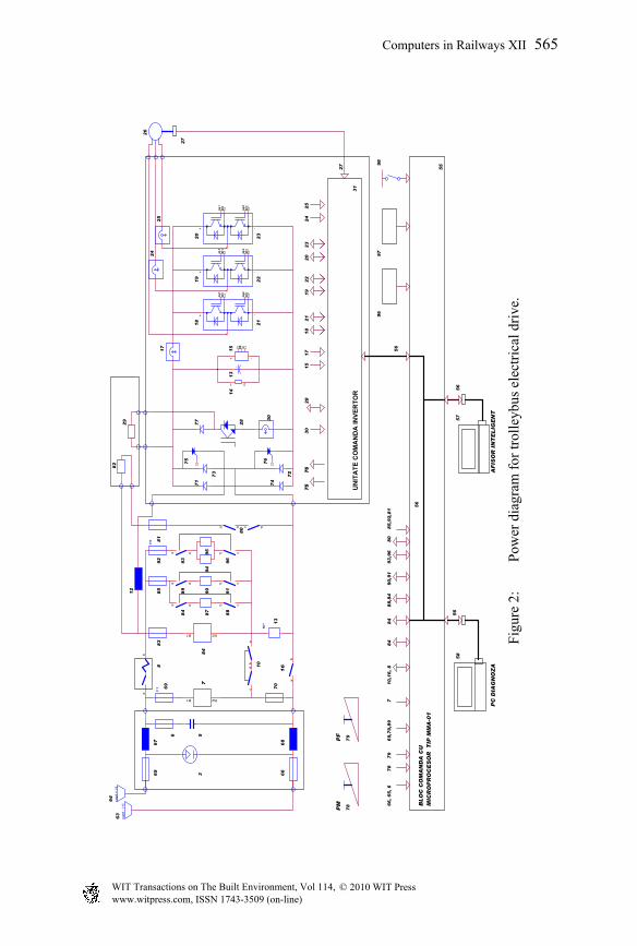
Figure 2 presents the electrical principle scheme for the driving of a trolley equipped with a three-phase inverter and a three-phase asynchronous traction motor. The nominal input voltage of 750 Vcc or 600 Vcc is transmitted to the trolley’s equipment by 2 current collectors 63 and 64 and fuses 65 and 66. This voltage is applied to the discharger 3. At the discharger’s terminals 3, the radio parasites filter that is made of two inductances 67 and 68, a capacitor 5 and the thermic fuse 6.
www.witpress.com, ISSN 1743-3509 (on-line) WIT Transactions on The Built Environment, Vol 114, © 2010 WIT Press
564 Computers in Railways XII
Fig
ure
2:
Pow
er d
iagr
am f
or tr
olle
ybus
ele
ctri
cal d
rive
.
UN
ITA
TE
CO
MA
ND
A IN
VE
RT
OR
56
56
AF
ISO
R I
NT
EL
IGE
NT
16
56
97
96
- +M
-+
64
81
~
+ -
G1
E1
G2
E2
+
98
71
75
73
77 3
0
28
72
74
76
~
+ -
G1
E1
G2
E2
~
+ -
G1
E1
G2
E2
1 2
84
14
15
13
17
26
18
27
20
19
22
21
23
93
,96
31
57
55
78
58
85
,92
,81
6
9,7
0,8
9
24
25
RP
B1 B2
17
ca
pt
- [+
]
cd
20
23
PC
DIA
GN
OZ
A
F1
cd
24
cd
25
27
c d
ca
pt
+ [
-]
ab
80
ab
PM
PF
ab
a b
F8
ab
B1 B2
12
63
66
65
68
67
53
7
13
70
69
10
83
88
59
2
84
80
88
89
87
93
94
90
91
95
96
a b
29
a b
82
56
cd
796
84
76
75
28
30
15
21
18
19
22
BL
OC
CO
MA
ND
A C
U
MIC
RO
PR
OC
ES
OR
T
IP M
MA
-01
66
, 6
5, 6
78
84
88
,84
90
,91
79
71
0,1
6, 8
www.witpress.com, ISSN 1743-3509 (on-line) WIT Transactions on The Built Environment, Vol 114, © 2010 WIT Press
Computers in Railways XII 565

The voltage from the output terminals of the inductance 67, through a fast main switch 8 that provides short-circuit and overload protection, and through an inductance 12, on one side and through the fuse 70, of an auxiliary charge contactor 10 and a charge current limitation resistor, it’s applied to a rectifier with four diodes 71, 72, 73 and 74, so that no matter the contact line polarity, the voltage applied to A terminal has the same polarity. In this way, the trolley can easily run in the garage or on track, being supplied by the lines of the trolley’s that run in the opposite direction, having a different polarity. Usually the closest line to the sidewalk has a minus polarity. In parallel on the capacitor 13 is a fast discharge resistor of the capacitor 14 and a input voltage filter transducer 15. Figure 2: Power diagram for trolleybus electrical drive After an optimum short time, one of the main contactors 16 is closed, that allows, after the capacitor 13 has charged to a reasonable voltage, the supply of a three-phase inverter (made of 6 IGBT transistors – 18...23), through a total current transducer 17. The three-phase inverter supply through two phase current transducers 24 and 25, an asynchronous three-phase traction motor 26, that is connected to a overspeed and position transducer that measures the motors overspeed and determines the rotation direction. With the help of a rheostatic breaking transistor 28, of a direction diode 77 and of a rheostatic breaking resistor 29, we can introduce rheostatic breaking; the breaking current is measured by a rheostatic breaking current transducer 30. The inverter is commanded to supply the traction motor with variable voltage and frequency, following the statoric field of the motor, by a inverter command block 31, made with a master microprocessor and one or more slave microprocessors. The inverter command block 31 assures the traction and energy saving electrical breaking regimes, in which case are commanded two thyristors 75 and 76, that allow the transfer of the electrical breaking saved energy to the contact lines. When the network does not receive all the commanded breaking energy, the start of the rheostatic break command is given, as a difference between the asked break and the one with energy saving. The functioning of the transistor inverter is ensured by the command of the transistors through this command block that receives a series of information from the total current transducer taken by the inverter 17, from the rheostatical breaking current transducer 30 and from the over speed and position transducer 27. The command, surveillance and diagnosis of the entire trolley are done by a main command block 55, that receives a series of information from the inverter command block through the data highway 56, but also from the other equipment and electrical and mechanical elements: pedals 78 and breaks 79, thermic fuses, input voltage transducer 7, auxiliary services static source 84, body voltage sensor 96, closed doors sensor 97, stationary break contact 98. In the driver’s cabin there is an intelligent display 57 that receives information through the highway 56, and when needed can be connected to a laptop computer 58 to collect all the events from the main command block’s diagnosis system.
www.witpress.com, ISSN 1743-3509 (on-line) WIT Transactions on The Built Environment, Vol 114, © 2010 WIT Press
566 Computers in Railways XII

4 The three-phase inverter command block
Figure 3 presents an example of command, adjustment, control and diagnosis block with microprocessors, used for the command of inverters on trams and trolleys. The main microprocessor command block for the three-phase force inverter 31 is done with a microprocessor 100 that contains a RAM memory with a battery 101 to memorize the events. Figure 3 presents the command block for the inverter 1 from Figure 1. The analogical measurements from the inverter input voltage transducer 15, from the current transducers: inverter total current 17 and phase currents 24 an 25 enter an interface as analogical inputs 102, in which each analogical input signal is conditioned, filtrated, standardized and then applied to an analog to digital converter, so that the output signals can be read by the microprocessor that sends them by a highway 103 to the microprocessor 100. The logical inputs, usually YES or NO: command the inverter 61, command the emergency break 63 and a signal from a radiator temperature thermostat with IGBT transistors inverter 104; enter an interface block as logical inputs 105 where they are applied to optocouplers and then transmitted through the highway 105 as logical signal applicable to the microprocessor 100. The signal from the speed and position transducer 27 enter a rotor over speed and position interface block 106, where it’s conditioned, filtrated, standardized, so that the output signal can be used by the microprocessor, being transmitted through the highway 103 to the microprocessor 100. The inputs from the microprocessor 100 sent through the highways 56 (from the central command block) and 103 are processed by the microprocessor that has programmes for the voltage, current and traction motor over speed regulators and are transmitted on a command highway 107 to a command block 108, that through transistor command highway 109 commands the IGBT transistors (18, 19, 20, 21, 22, 23) from the inverter. The commands for the transistors enter a block that reads large currents in the transistors 110, that can stop the transmission of impulses to the transistors, by doing so blocking the inverter, that transmits through the highways 107 and 103 to a detection and signalising block of the malfunction 111, that commands an optical/ acoustical warning in the central command block 55. The microprocessor command block for the command of the rheostatical break transistor is realized with a microprocessor 112. The analogical inputs from the voltage transducer 15 and from the rheostatical break current transducer 30 enter an analogical inputs interface 113, in which every analogical signal is conditioned, filtered, standardized and then applied to a analogical-digital converter, so that the output signals can be used by the microprocessor, that are transmitted through a highway 114 to the microprocessor 112. The logical inputs, YES or NO: command the break from the controller 59, from the emergency break button 61 and from a radiator temperature thermostat with thyristor 115, enter a logical inputs interface block 116, where they are applied to optocouplers and then transmitted though the data highway 114 as logical signals applicable to the microprocessor 112. The inputs from the microprocessor 112 received through the highway 114 are processed by the microprocessor 112 that
www.witpress.com, ISSN 1743-3509 (on-line) WIT Transactions on The Built Environment, Vol 114, © 2010 WIT Press
Computers in Railways XII 567

Fig
ure
3:
Blo
ck d
iagr
am f
or th
e co
mm
and,
adj
ustm
ent,
cont
rol a
nd d
iagn
osis
of
the
elec
tric
al d
rive
on
tram
s an
d tr
olle
ys.
www.witpress.com, ISSN 1743-3509 (on-line) WIT Transactions on The Built Environment, Vol 114, © 2010 WIT Press
568 Computers in Railways XII
Fig
ure
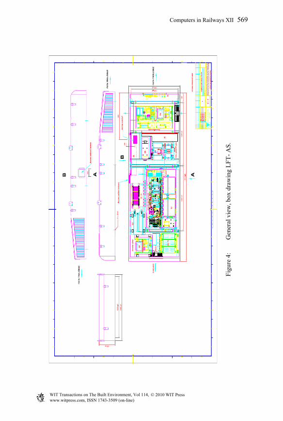
4:
Gen
eral
vie
w, b
ox d
raw
ing
LF
T-
AS.
www.witpress.com, ISSN 1743-3509 (on-line) WIT Transactions on The Built Environment, Vol 114, © 2010 WIT Press
Computers in Railways XII 569
contains programmes for the voltage and current regulators, are sent through a command highway 117 to a command block 118, that through a rheostatical break thyristor command highway 119 commands the IGBT thyristor 28. The commands for the thyristor enter a large current thyristor sensor block 120, that can stop the transmission of impulses to the thyristor, by doing so blocking the thyristor, that transmits though the highways 117 and 114 to a detection and warning block that the rheostatical break thyristor 121 malfunctioned, and commands an optical/acoustical warning to the central command block 55 through the data highway 56 and the main information is sent to the diagnosis laptop 58. The nominal voltage filter 24 Vdc, 122 supplies two converters cc/cc – 123 and 124 – that supply with corresponding voltages the microprocessors and the block components of the inverter command block 31.
5 Execution of the electrical equipment for the asynchronous motor trolley
The driving equipment with inverter is placed on the roof of the trolley. The signal processor command of the traction inverter is included with the power electronics (IGBT), and the command is done by serial transmission of the commands to the SATREC-MMA block. The components of the electrical equipment from the LFT-AS are: o Traction inverter block IVF; o EMC continuous current network supply filter with ultra fast safety fuse o Ultra fast automated switch QL o Network voltage sensor SPTR o Line contactor KL and pre-charger circuit KR+RP o Services contactors K1…K3 o Crossing operating contactors KD o Ultra fast safety fuses 1250Vcc F1, F2, F5…F9 o Auxiliary services static converter type CS11T-SA o Static supply converter for the air conditioning converter CS11T-CL The roof box project contains all the equipment mounted on the roof. The positioning was made so that the mass of the entire equipment would be reduced and the gravity center would be moved as far back as possible.
6 Conclusions
According to their final destination, the equipment must satisfy all the European standards and requirements regarding safety and comfort for the urban traffic. The reliability must be very high and maintenance operations must be simple and easy to do for medium trained personnel. For this is necessary to have a high level of diagnose and the possibility to isolate the damage very quickly. To fulfill this requirements, ICPE SAERP, traced very sharply the development of the semiconductor technology, and electrotechnical materials, the final goal being to increase the performance of the products.
www.witpress.com, ISSN 1743-3509 (on-line) WIT Transactions on The Built Environment, Vol 114, © 2010 WIT Press
570 Computers in Railways XII

The control of the drives are made entirely based on specific designs developed inside the company, beginning from the PCB design and physical stage of the boards, and in the end, final testing and development of the software for control and diagnosis. The electrical drive for trams or trolleys, based on asynchronous motors are state of the art designs, which use the last technology for control and power diagrams. The final performance concerning energy saving and the comfort of the passengers is proved, the power savings against a classical drive is about 30%. The analysis made by various authorities in Europe, reached the conclusion that the pollution in the big cities may be reduced if an well organized urban transportation will be created, with modern means of transportation, especially those that use underground and surface subway networks (on special routes, including light-subway), completed by connection lines that use tramcars, trolley buses and hybrid fuel cell based electrical autobuses that are parallel connected with modern electrical storage batteries. A strong urban transportation network will reduce substantially the number of automobiles and so the pollution can be strongly diminished. In addition to this, through a well-organized urban electric transportation, we can assure an optimum run of passengers from the big cities, with an acceptable comfort and safety. All of this implies large investments distributed on long time periods and respectively subsidies from the city halls that should cover the exploitation costs after renouncing of most of the diesel autobuses and powerful expansion of non-polluting electrical transportation. This is well covered in the European Recommendation COM (2007) 551 final [1, p. 1, 9, 19, 20]: Local authorities cannot face all these issues on their own: there is need for
cooperation and coordination at European level. The vital issue of urban mobility needs to be addressed as part of collective effort at levels: local, regional, national and European. The European Union must play a leading role in order to focus attention on this issue.
Extension, rehabilitation and upgrading of clean urban public transport such as trolley buses, trams, metros and suburban rail as well as other sustainable urban transport projects should continue to be promoted and supported by the UE.
According to a recent study, over 40% of the urban tram and light rail fleet in the EU-15 and 67% of the fleet in the new Member States is over 20 years old and ought to be replaced before 2020.
At EU level several sources of financing are available, for instance the Structural Funds, the Cohesion Fund and loans from the European investment Bank. As in the past, the EU’s Cohesion Policy will remain an important source of funds in the eligible region during the period 2007-2013.
According to the programming documents, European Regional Development Fund – ERDF- and Cohesion Fund will contribute to almost € 8 billion for urban transport during the 2007-2013 period.
www.witpress.com, ISSN 1743-3509 (on-line) WIT Transactions on The Built Environment, Vol 114, © 2010 WIT Press
Computers in Railways XII 571

The cohesion instruments in the current period 2007- 2013 provide a more broad and solid basis for co-financing urban transport and collective transport across Europe. The ERDF and Cohesion Fund regulations make explicit reference to clean urban transport and public transport but also, for the first time, to integrated strategies for the clean transport.
References
[1] Green Paper. Towards a new culture for urban mobility. Commission of the European Communities. Brussels, 25.9.2007-COM (2007) 551 FINAL.
[2] Radulescu, V., Strainescu, I., Gheorghe, S., Tudor, E., Moroianu, L., Serbu V., Goia, C., Bozas, F., Dascalu, A., Braslasu, D., Tanase, M., Mitroi, G., Badea, S., Sburlan, I., Ungurasu, C., Lupu, V., Radulescu, B., Driving equipments made by Icpe Saerp for urban electric transport vehicles, Proc. of the Urban Transport XIV, Urban Transport and the Environment in the 21st Century, eds. C.A.Brebbia, Malta, pp.203-211, 2008
[3] Strainescu, I., Tudor, E., Serbu, V., Bozas, F., Badea, s., Speed control of subway and trams, Proc. of the Urban Transport XIV, Urban Transport and the Environment in the 21st Century, eds. C.A.Brebbia, Malta, pp.515–223, 200
www.witpress.com, ISSN 1743-3509 (on-line) WIT Transactions on The Built Environment, Vol 114, © 2010 WIT Press
572 Computers in Railways XII