drogue tracking using 3d flash lidar for autonomous aerial ... · pdf filedrogue tracking...
TRANSCRIPT
Drogue Tracking Using 3D Flash LIDAR for Autonomous Aerial
Refueling
Chao-I Chen* and Roger Stettner
Advanced Scientific Concepts, Inc., 135 E. Ortega Street, Santa Barbara, CA, USA 93101
ABSTRACT
Autonomous aerial refueling (AAR) is an important capability for an unmanned aerial vehicle (UAV) to increase its
flying range and endurance without increasing its size. This paper presents a novel tracking method that utilizes both 2D
intensity and 3D point-cloud data acquired with a 3D Flash LIDAR sensor to establish relative position and orientation
between the receiver vehicle and drogue during an aerial refueling process. Unlike classic, vision-based sensors, a 3D
Flash LIDAR sensor can provide 3D point-cloud data in real time without motion blur, in the day or night, and is capable
of imaging through fog and clouds. The proposed method segments out the drogue through 2D analysis and estimates
the center of the drogue from 3D point-cloud data for flight trajectory determination. A level-set front propagation
routine is first employed to identify the target of interest and establish its silhouette information. Sufficient domain
knowledge, such as the size of the drogue and the expected operable distance, is integrated into our approach to quickly
eliminate unlikely target candidates. A statistical analysis along with a random sample consensus (RANSAC) is
performed on the target to reduce noise and estimate the center of the drogue after all 3D points on the drogue are
identified. The estimated center and drogue silhouette serve as the seed points to efficiently locate the target in the next
frame.
Keywords: autonomous aerial refueling, 3D Flash LIDAR, unmanned aerial vehicle, level set, 3D point-cloud, tracking,
target identification
1. INTRODUCTION
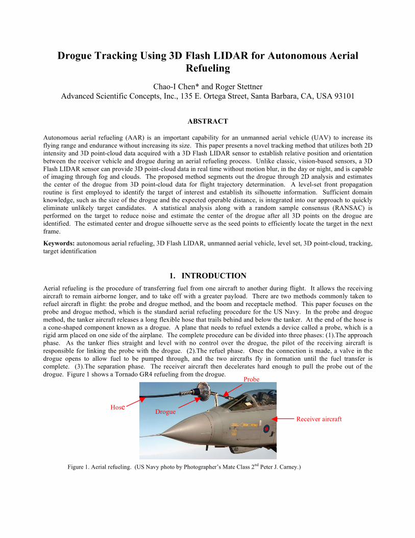
Aerial refueling is the procedure of transferring fuel from one aircraft to another during flight. It allows the receiving
aircraft to remain airborne longer, and to take off with a greater payload. There are two methods commonly taken to
refuel aircraft in flight: the probe and drogue method, and the boom and receptacle method. This paper focuses on the
probe and drogue method, which is the standard aerial refueling procedure for the US Navy. In the probe and drogue
method, the tanker aircraft releases a long flexible hose that trails behind and below the tanker. At the end of the hose is
a cone-shaped component known as a drogue. A plane that needs to refuel extends a device called a probe, which is a
rigid arm placed on one side of the airplane. The complete procedure can be divided into three phases: (1).The approach
phase. As the tanker flies straight and level with no control over the drogue, the pilot of the receiving aircraft is
responsible for linking the probe with the drogue. (2).The refuel phase. Once the connection is made, a valve in the
drogue opens to allow fuel to be pumped through, and the two aircrafts fly in formation until the fuel transfer is
complete. (3).The separation phase. The receiver aircraft then decelerates hard enough to pull the probe out of the
drogue. Figure 1 shows a Tornado GR4 refueling from the drogue.
Figure 1. Aerial refueling. (US Navy photo by Photographer’s Mate Class 2nd
Peter J. Carney.)
Hose
Probe
Drogue Receiver aircraft
Drogue Tracking Using 3D Flash LIDAR for Autonomous Aerial Refueling (Chen – Stettner) Page 2 of 11
*[email protected]; phone 1 805 966-3331; fax 1 805 966-0059; asc3d.com
The approach phase can be further divided into two steps: the flight formatting step and the final docking step where the
connection between the probe and the drogue is made. Current techniques applied in autonomous aerial refueling
(AAR) systems provide satisfactory results in guiding aircraft to a position proximate to the tanker and maintaining the
required close formation1~2
. These AAR systems which combine both global positioning systems (GPS) and inertial
navigation systems (INS) have focused on flight formation guidance and are not well-suited for the final docking phase.
During the final docking phase, some aerodynamic effects occur on the receiver aircraft as well as the drogue and hose
positions. Several effects on the drogue and hose were reported in the flight tests3~4
. Because it is difficult to install
GPS and INS sensors on a drogue, the dynamics information of the drogue and hose cannot be captured, which makes
docking challenging. Moreover, GPS’ low update rate, 1 Hz, is generally considered insufficient for the final docking
step, which is heavily relies on object tracking and terminal guidance technologies.
Many recent terminal guidance technologies for aerial refueling docking utilize landmarks and computer vision based
algorithms5~9
. It is, however, a difficult task due to loss of information caused by projection of the 3D world on 2D
images. In addition to this inherent characteristic of ambiguity, it is also well known that vision based technologies are
usually unreliable in low visibility conditions, such as in a dark night or in a foggy environment. The accuracy
deteriorates significantly as the 2D image quality declines. For more detail on related technologies, the interested reader
is encouraged to consult Mao and Eke’s survey paper10
.
2. METHOD
An alternative combination of a Flash LIDAR sensor and a tracking algorithm for aerial refueling terminal guidance is
presented in this paper that has a potential to overcome the obstacles discussed above. Different modules and their
functions are described in detail below.
2.1 ASC’s 3D Flash LIDAR Camera
ASC’s 3D Flash LIDAR cameras provide 2D intensity images plus depth information in real time11
. Converting each
2D point into 3D space is straight forward through one simple equation. No complicated mathematical inference is
required. Because the calculated 3D positions are relative to the camera location, it is possible to compute every point’s
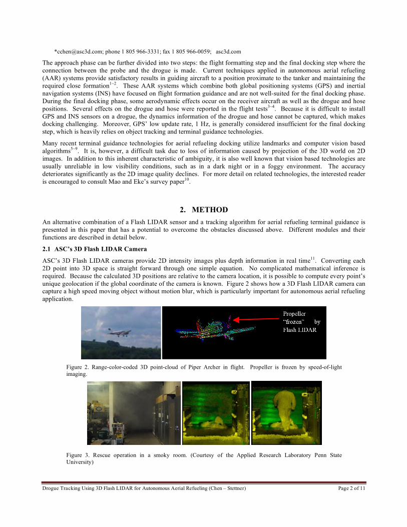
unique geolocation if the global coordinate of the camera is known. Figure 2 shows how a 3D Flash LIDAR camera can
capture a high speed moving object without motion blur, which is particularly important for autonomous aerial refueling
application.
Figure 2. Range-color-coded 3D point-cloud of Piper Archer in flight. Propeller is frozen by speed-of-light
imaging.
Figure 3. Rescue operation in a smoky room. (Courtesy of the Applied Research Laboratory Penn State
University)
Drogue Tracking Using 3D Flash LIDAR for Autonomous Aerial Refueling (Chen – Stettner) Page 3 of 11
In addition to the desired characteristics listed above, the 3D Flash LIDAR cameras are capable of imaging day or night
and through fog and clouds while providing a total 16384 (128 X 128) 3D points for each frame. Figure 3 demonstrates
the camera’s ability to see through particle obscurants such as smoke and fog. The left most 2D RGB image shows a
smoke filled room. The center range-color-coded image obtained by a Flash LIDAR camera shows a person overcome
with smoke that could not be seen in the traditional 2D RGB image. The far right image in Figure 3 shows a rescue
worker approaching the fallen individual. With the demonstrated capability, it is possible for an UAV to carry out
missions even under low visibility conditions.
2.2 Proposed Tracking Method
Significant progress in object tracking has been made in the past few years12
. The majority of research has focused on
tracking objects in 2D RGB image data alone. Although these algorithms have been applied on various applications
with some degree of success, they are often confused if the image contains little color variation. This confusion,
however, can be easily resolved with the third dimension information – the depth. A simple segmentation algorithm can
be designed to identify a white box located in front of a white wall – impossible with traditional 2D images for example
– if the information of depth is available.
After carefully reviewing many available techniques in literature, we believe there is a need to design a tailored
algorithm for the 3D Flash LIDAR camera to achieve optimal tracking performance for the autonomous aerial refueling
application. To constrain the scope of the problem, prior domain knowledge should be incorporated in our approach.
Research in the area of object recognition and classification has shown improved results after exploiting domain
knowledge13-14
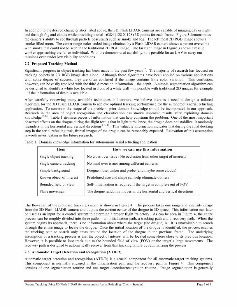
. Table 1 itemizes pieces of information that can help constrain the problem. One of the most important
observed effects on the drogue during the flight test is that in light turbulence, the drogue does not stabilize; it randomly
meanders in the horizontal and vertical directions3, 4, 10
. This valuable information indicates that during the final docking
step in the aerial refueling task, frontal images of the drogue can be reasonably expected. Relaxation of this assumption
is worth investigating in the future research.
Table 1. Domain knowledge information for autonomous aerial refueling application
Item How we can use this information
Single object tracking No cross over issue / No occlusion from other target of interests
Single camera tracking No hand over issues among different cameras
Simple background Drogue, hose, tanker and probe (and maybe some clouds)
Known object of interest Predefined size and shape can help eliminate outliers
Bounded field of view Self-initialization is required if the target is complete out of FOV
Plane movement The drogue randomly moves in the horizontal and vertical directions
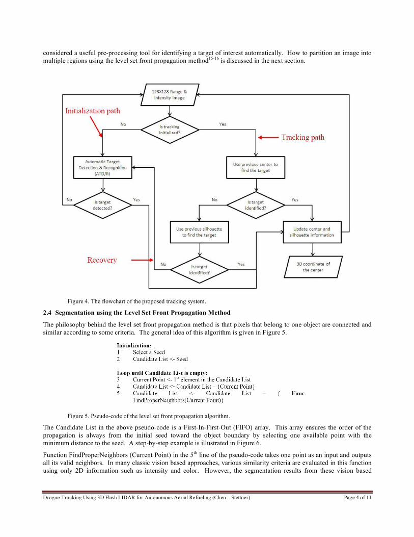
The flowchart of the proposed tracking system is shown in Figure 4. The process takes one range and intensity image
from the 3D Flash LIADR camera and outputs the current center of the drogue in 3D space. This information can later
be used as an input for a control system to determine a proper flight trajectory. As can be seen in Figure 4, the entire
process can be roughly divided into three paths – an initialization path, a tracking path and a recovery path. When the
system begins its approach, there is no information about where the target (the drogue) is. It is unavoidable to search
through the entire image to locate the drogue. Once the initial location of the drogue is identified, the process enables
the tracking path to search only areas around the location of the drogue in the previous frame. The underlying
assumption of a tracking process is that the object of interest will be located somewhere close to its previous location.
However, it is possible to lose track due to the bounded field of view (FOV) or the target’s large movements. The
recovery path is designed to automatically recover from this tracking failure by reinitializing the process.
2.3 Automatic Target Detection and Recognition (ATD/R)
Automatic target detection and recognition (ATD/R) is a crucial component for all automatic target tracking systems.
This component is normally engaged in the initialization path and the recovery path in Figure 4. This component
consists of one segmentation routine and one target detection/recognition routine. Image segmentation is generally
Drogue Tracking Using 3D Flash LIDAR for Autonomous Aerial Refueling (Chen – Stettner) Page 4 of 11
considered a useful pre-processing tool for identifying a target of interest automatically. How to partition an image into
multiple regions using the level set front propagation method15-16
is discussed in the next section.
Figure 4. The flowchart of the proposed tracking system.
2.4 Segmentation using the Level Set Front Propagation Method
The philosophy behind the level set front propagation method is that pixels that belong to one object are connected and
similar according to some criteria. The general idea of this algorithm is given in Figure 5.
Figure 5. Pseudo-code of the level set front propagation algorithm.
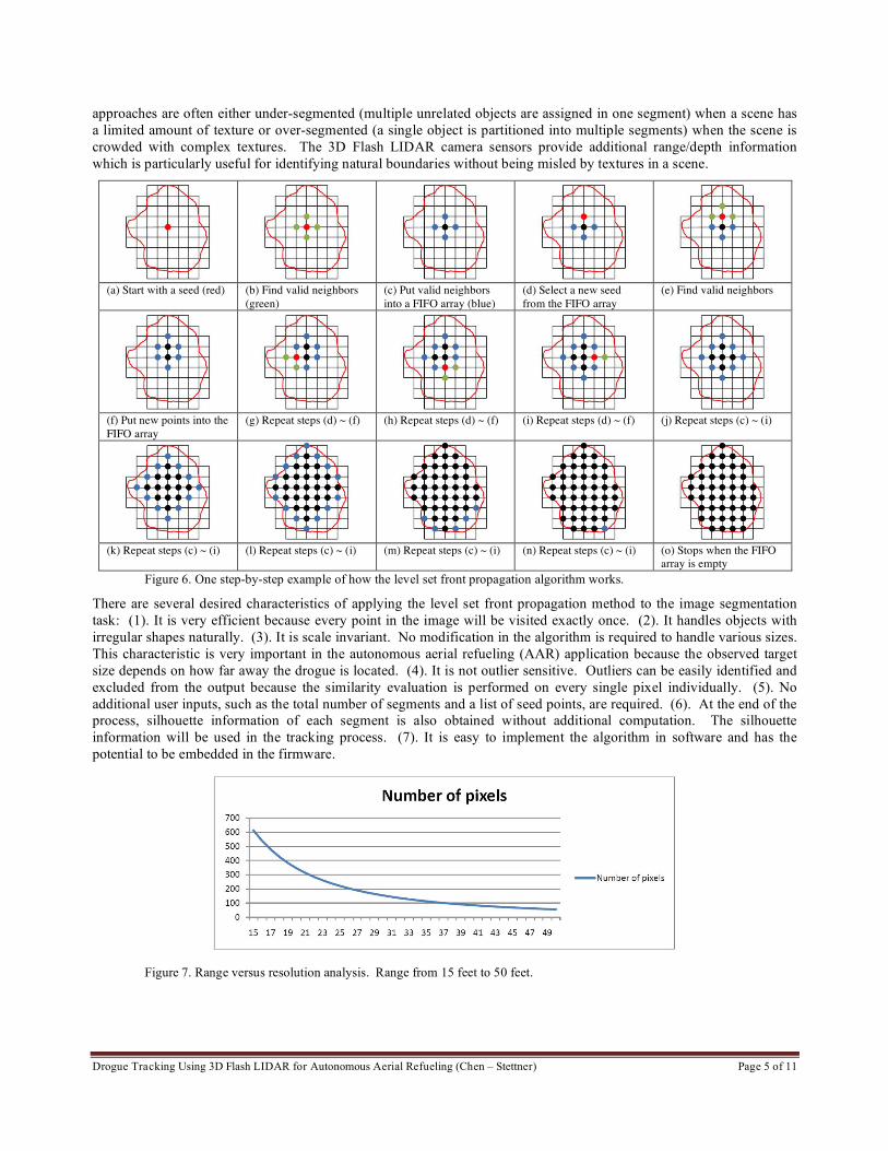
The Candidate List in the above pseudo-code is a First-In-First-Out (FIFO) array. This array ensures the order of the
propagation is always from the initial seed toward the object boundary by selecting one available point with the
minimum distance to the seed. A step-by-step example is illustrated in Figure 6.
Function FindProperNeighbors (Current Point) in the 5th
line of the pseudo-code takes one point as an input and outputs
all its valid neighbors. In many classic vision based approaches, various similarity criteria are evaluated in this function
using only 2D information such as intensity and color. However, the segmentation results from these vision based
Drogue Tracking Using 3D Flash LIDAR for Autonomous Aerial Refueling (Chen – Stettner) Page 5 of 11
approaches are often either under-segmented (multiple unrelated objects are assigned in one segment) when a scene has
a limited amount of texture or over-segmented (a single object is partitioned into multiple segments) when the scene is
crowded with complex textures. The 3D Flash LIDAR camera sensors provide additional range/depth information
which is particularly useful for identifying natural boundaries without being misled by textures in a scene.
(a) Start with a seed (red) (b) Find valid neighbors
(green)
(c) Put valid neighbors
into a FIFO array (blue)
(d) Select a new seed
from the FIFO array
(e) Find valid neighbors
(f) Put new points into the
FIFO array
(g) Repeat steps (d) ~ (f) (h) Repeat steps (d) ~ (f) (i) Repeat steps (d) ~ (f) (j) Repeat steps (c) ~ (i)
(k) Repeat steps (c) ~ (i) (l) Repeat steps (c) ~ (i) (m) Repeat steps (c) ~ (i) (n) Repeat steps (c) ~ (i) (o) Stops when the FIFO
array is empty
Figure 6. One step-by-step example of how the level set front propagation algorithm works.
There are several desired characteristics of applying the level set front propagation method to the image segmentation
task: (1). It is very efficient because every point in the image will be visited exactly once. (2). It handles objects with
irregular shapes naturally. (3). It is scale invariant. No modification in the algorithm is required to handle various sizes.
This characteristic is very important in the autonomous aerial refueling (AAR) application because the observed target
size depends on how far away the drogue is located. (4). It is not outlier sensitive. Outliers can be easily identified and
excluded from the output because the similarity evaluation is performed on every single pixel individually. (5). No
additional user inputs, such as the total number of segments and a list of seed points, are required. (6). At the end of the
process, silhouette information of each segment is also obtained without additional computation. The silhouette
information will be used in the tracking process. (7). It is easy to implement the algorithm in software and has the
potential to be embedded in the firmware.
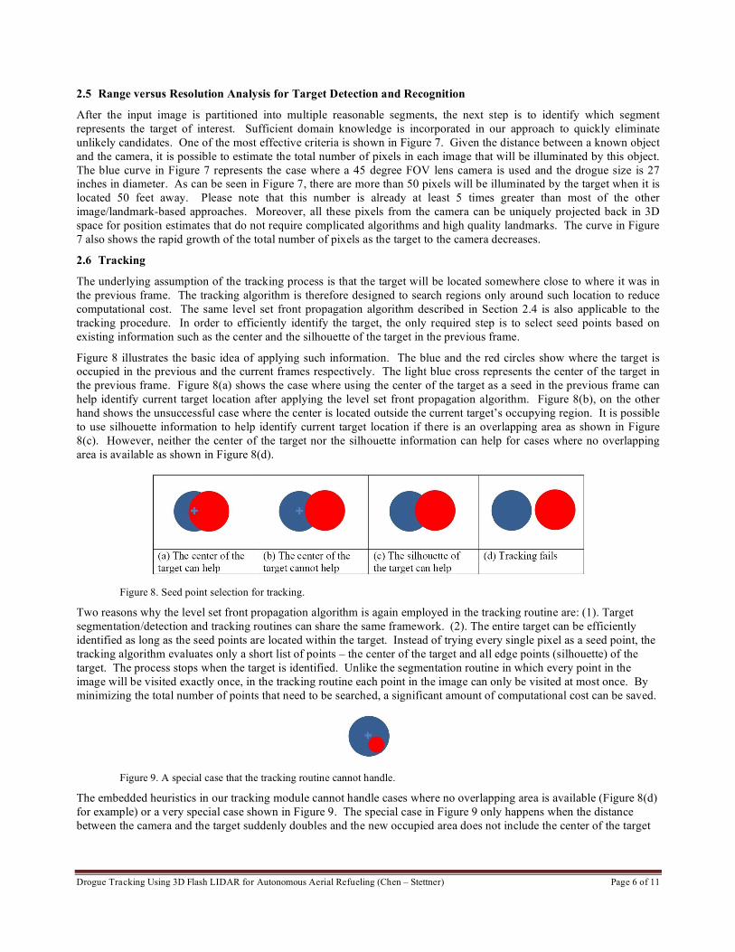
Figure 7. Range versus resolution analysis. Range from 15 feet to 50 feet.
Drogue Tracking Using 3D Flash LIDAR for Autonomous Aerial Refueling (Chen – Stettner) Page 6 of 11
2.5 Range versus Resolution Analysis for Target Detection and Recognition
After the input image is partitioned into multiple reasonable segments, the next step is to identify which segment
represents the target of interest. Sufficient domain knowledge is incorporated in our approach to quickly eliminate
unlikely candidates. One of the most effective criteria is shown in Figure 7. Given the distance between a known object
and the camera, it is possible to estimate the total number of pixels in each image that will be illuminated by this object.
The blue curve in Figure 7 represents the case where a 45 degree FOV lens camera is used and the drogue size is 27
inches in diameter. As can be seen in Figure 7, there are more than 50 pixels will be illuminated by the target when it is
located 50 feet away. Please note that this number is already at least 5 times greater than most of the other
image/landmark-based approaches. Moreover, all these pixels from the camera can be uniquely projected back in 3D
space for position estimates that do not require complicated algorithms and high quality landmarks. The curve in Figure
7 also shows the rapid growth of the total number of pixels as the target to the camera decreases.
2.6 Tracking
The underlying assumption of the tracking process is that the target will be located somewhere close to where it was in
the previous frame. The tracking algorithm is therefore designed to search regions only around such location to reduce
computational cost. The same level set front propagation algorithm described in Section 2.4 is also applicable to the
tracking procedure. In order to efficiently identify the target, the only required step is to select seed points based on
existing information such as the center and the silhouette of the target in the previous frame.
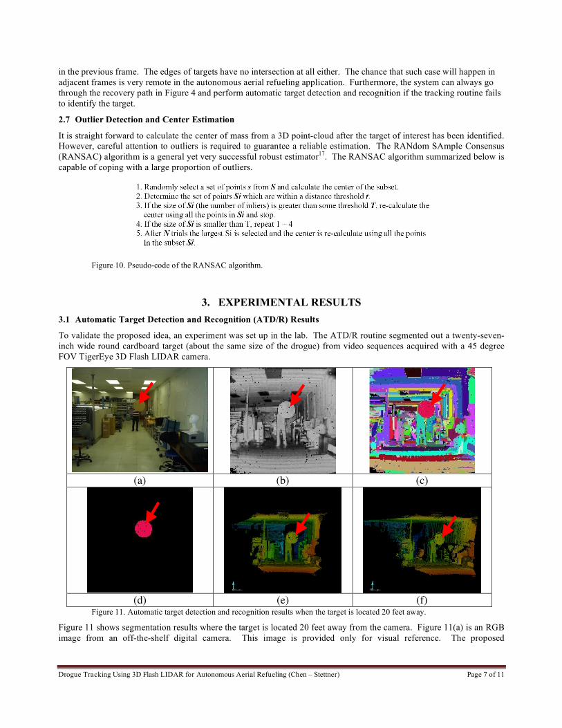
Figure 8 illustrates the basic idea of applying such information. The blue and the red circles show where the target is
occupied in the previous and the current frames respectively. The light blue cross represents the center of the target in
the previous frame. Figure 8(a) shows the case where using the center of the target as a seed in the previous frame can
help identify current target location after applying the level set front propagation algorithm. Figure 8(b), on the other
hand shows the unsuccessful case where the center is located outside the current target’s occupying region. It is possible
to use silhouette information to help identify current target location if there is an overlapping area as shown in Figure
8(c). However, neither the center of the target nor the silhouette information can help for cases where no overlapping
area is available as shown in Figure 8(d).
Figure 8. Seed point selection for tracking.
Two reasons why the level set front propagation algorithm is again employed in the tracking routine are: (1). Target
segmentation/detection and tracking routines can share the same framework. (2). The entire target can be efficiently
identified as long as the seed points are located within the target. Instead of trying every single pixel as a seed point, the
tracking algorithm evaluates only a short list of points – the center of the target and all edge points (silhouette) of the
target. The process stops when the target is identified. Unlike the segmentation routine in which every point in the
image will be visited exactly once, in the tracking routine each point in the image can only be visited at most once. By
minimizing the total number of points that need to be searched, a significant amount of computational cost can be saved.
Figure 9. A special case that the tracking routine cannot handle.
The embedded heuristics in our tracking module cannot handle cases where no overlapping area is available (Figure 8(d)
for example) or a very special case shown in Figure 9. The special case in Figure 9 only happens when the distance
between the camera and the target suddenly doubles and the new occupied area does not include the center of the target
Drogue Tracking Using 3D Flash LIDAR for Autonomous Aerial Refueling (Chen – Stettner) Page 7 of 11
in the previous frame. The edges of targets have no intersection at all either. The chance that such case will happen in
adjacent frames is very remote in the autonomous aerial refueling application. Furthermore, the system can always go
through the recovery path in Figure 4 and perform automatic target detection and recognition if the tracking routine fails
to identify the target.
2.7 Outlier Detection and Center Estimation
It is straight forward to calculate the center of mass from a 3D point-cloud after the target of interest has been identified.
However, careful attention to outliers is required to guarantee a reliable estimation. The RANdom SAmple Consensus
(RANSAC) algorithm is a general yet very successful robust estimator17
. The RANSAC algorithm summarized below is
capable of coping with a large proportion of outliers.
Figure 10. Pseudo-code of the RANSAC algorithm.
3. EXPERIMENTAL RESULTS
3.1 Automatic Target Detection and Recognition (ATD/R) Results
To validate the proposed idea, an experiment was set up in the lab. The ATD/R routine segmented out a twenty-seven-
inch wide round cardboard target (about the same size of the drogue) from video sequences acquired with a 45 degree
FOV TigerEye 3D Flash LIDAR camera.
(a) (b) (c)
(d) (e) (f)
Figure 11. Automatic target detection and recognition results when the target is located 20 feet away.
Figure 11 shows segmentation results where the target is located 20 feet away from the camera. Figure 11(a) is an RGB
image from an off-the-shelf digital camera. This image is provided only for visual reference. The proposed
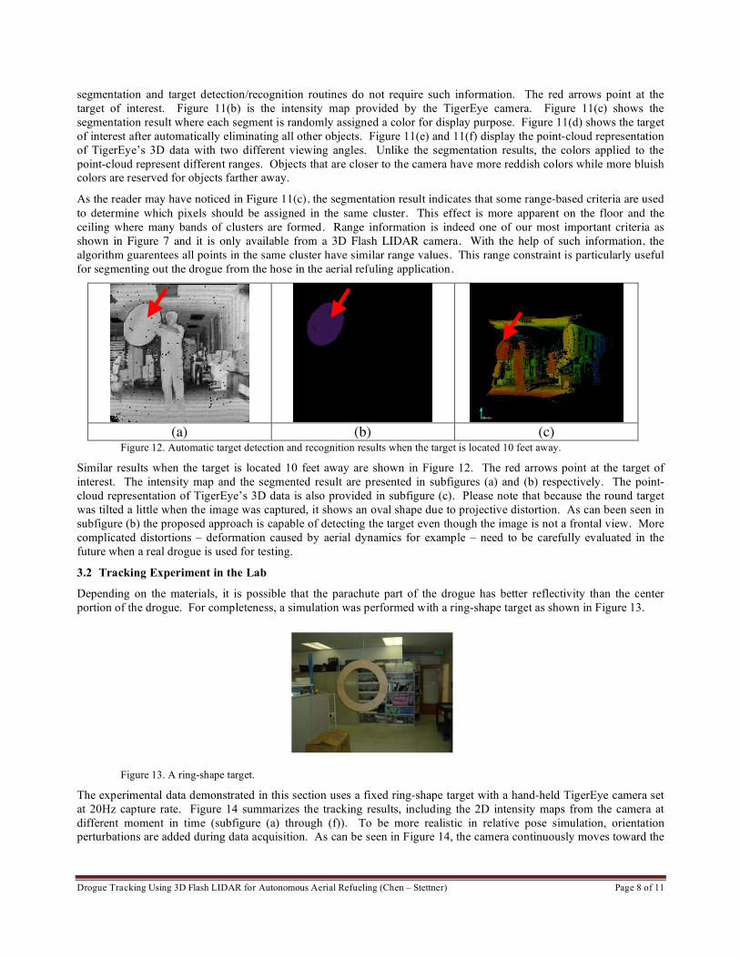
Drogue Tracking Using 3D Flash LIDAR for Autonomous Aerial Refueling (Chen – Stettner) Page 8 of 11
segmentation and target detection/recognition routines do not require such information. The red arrows point at the
target of interest. Figure 11(b) is the intensity map provided by the TigerEye camera. Figure 11(c) shows the
segmentation result where each segment is randomly assigned a color for display purpose. Figure 11(d) shows the target
of interest after automatically eliminating all other objects. Figure 11(e) and 11(f) display the point-cloud representation
of TigerEye’s 3D data with two different viewing angles. Unlike the segmentation results, the colors applied to the
point-cloud represent different ranges. Objects that are closer to the camera have more reddish colors while more bluish
colors are reserved for objects farther away.
As the reader may have noticed in Figure 11(c), the segmentation result indicates that some range-based criteria are used
to determine which pixels should be assigned in the same cluster. This effect is more apparent on the floor and the
ceiling where many bands of clusters are formed. Range information is indeed one of our most important criteria as
shown in Figure 7 and it is only available from a 3D Flash LIDAR camera. With the help of such information, the
algorithm guarentees all points in the same cluster have similar range values. This range constraint is particularly useful
for segmenting out the drogue from the hose in the aerial refuling application.
(a) (b) (c)
Figure 12. Automatic target detection and recognition results when the target is located 10 feet away.
Similar results when the target is located 10 feet away are shown in Figure 12. The red arrows point at the target of
interest. The intensity map and the segmented result are presented in subfigures (a) and (b) respectively. The point-
cloud representation of TigerEye’s 3D data is also provided in subfigure (c). Please note that because the round target
was tilted a little when the image was captured, it shows an oval shape due to projective distortion. As can been seen in
subfigure (b) the proposed approach is capable of detecting the target even though the image is not a frontal view. More
complicated distortions – deformation caused by aerial dynamics for example – need to be carefully evaluated in the
future when a real drogue is used for testing.
3.2 Tracking Experiment in the Lab
Depending on the materials, it is possible that the parachute part of the drogue has better reflectivity than the center
portion of the drogue. For completeness, a simulation was performed with a ring-shape target as shown in Figure 13.
Figure 13. A ring-shape target.
The experimental data demonstrated in this section uses a fixed ring-shape target with a hand-held TigerEye camera set
at 20Hz capture rate. Figure 14 summarizes the tracking results, including the 2D intensity maps from the camera at
different moment in time (subfigure (a) through (f)). To be more realistic in relative pose simulation, orientation
perturbations are added during data acquisition. As can be seen in Figure 14, the camera continuously moves toward the
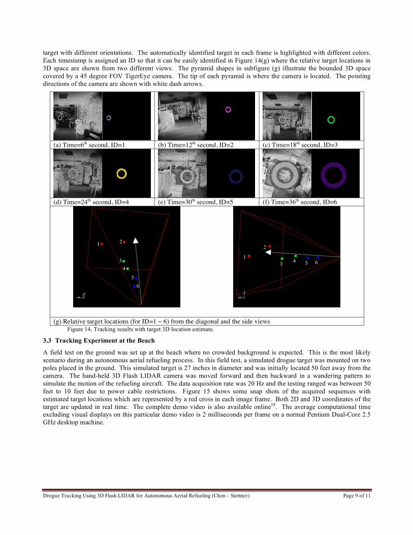
Drogue Tracking Using 3D Flash LIDAR for Autonomous Aerial Refueling (Chen – Stettner) Page 9 of 11
target with different orientations. The automatically identified target in each frame is highlighted with different colors.
Each timestamp is assigned an ID so that it can be easily identified in Figure 14(g) where the relative target locations in
3D space are shown from two different views. The pyramid shapes in subfigure (g) illustrate the bounded 3D space
covered by a 45 degree FOV TigerEye camera. The tip of each pyramid is where the camera is located. The pointing
directions of the camera are shown with white dash arrows.
(a) Time=6th second, ID=1 (b) Time=12th second, ID=2 (c) Time=18th second, ID=3
(d) Time=24th second, ID=4 (e) Time=30th second, ID=5 (f) Time=36th second, ID=6
(g) Relative target locations (for ID=1 ~ 6) from the diagonal and the side views
Figure 14. Tracking results with target 3D location estimate.
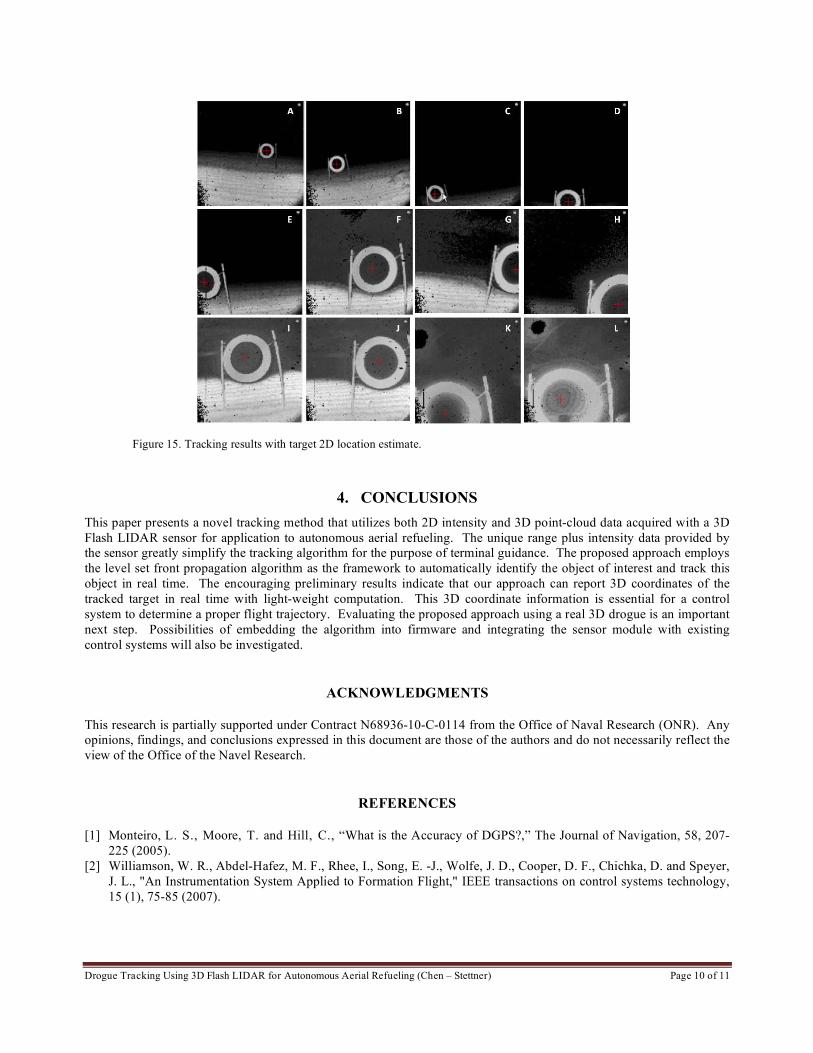
3.3 Tracking Experiment at the Beach
A field test on the ground was set up at the beach where no crowded background is expected. This is the most likely
scenario during an autonomous aerial refueling process. In this field test, a simulated drogue target was mounted on two
poles placed in the ground. This simulated target is 27 inches in diameter and was initially located 50 feet away from the
camera. The hand-held 3D Flash LIDAR camera was moved forward and then backward in a wandering pattern to
simulate the motion of the refueling aircraft. The data acquisition rate was 20 Hz and the testing ranged was between 50
feet to 10 feet due to power cable restrictions. Figure 15 shows some snap shots of the acquired sequences with
estimated target locations which are represented by a red cross in each image frame. Both 2D and 3D coordinates of the
target are updated in real time. The complete demo video is also available online18
. The average computational time
excluding visual displays on this particular demo video is 2 milliseconds per frame on a normal Pentium Dual-Core 2.5
GHz desktop machine.
1 2
4
5
3
6
1 4 5 6
2
3
Drogue Tracking Using 3D Flash LIDAR for Autonomous Aerial Refueling (Chen – Stettner) Page 10 of 11
Figure 15. Tracking results with target 2D location estimate.
4. CONCLUSIONS
This paper presents a novel tracking method that utilizes both 2D intensity and 3D point-cloud data acquired with a 3D
Flash LIDAR sensor for application to autonomous aerial refueling. The unique range plus intensity data provided by
the sensor greatly simplify the tracking algorithm for the purpose of terminal guidance. The proposed approach employs
the level set front propagation algorithm as the framework to automatically identify the object of interest and track this
object in real time. The encouraging preliminary results indicate that our approach can report 3D coordinates of the
tracked target in real time with light-weight computation. This 3D coordinate information is essential for a control
system to determine a proper flight trajectory. Evaluating the proposed approach using a real 3D drogue is an important
next step. Possibilities of embedding the algorithm into firmware and integrating the sensor module with existing
control systems will also be investigated.
ACKNOWLEDGMENTS
This research is partially supported under Contract N68936-10-C-0114 from the Office of Naval Research (ONR). Any
opinions, findings, and conclusions expressed in this document are those of the authors and do not necessarily reflect the
view of the Office of the Navel Research.
REFERENCES
[1] Monteiro, L. S., Moore, T. and Hill, C., “What is the Accuracy of DGPS?,” The Journal of Navigation, 58, 207-
225 (2005).
[2] Williamson, W. R., Abdel-Hafez, M. F., Rhee, I., Song, E. -J., Wolfe, J. D., Cooper, D. F., Chichka, D. and Speyer,
J. L., "An Instrumentation System Applied to Formation Flight," IEEE transactions on control systems technology,
15 (1), 75-85 (2007).

Drogue Tracking Using 3D Flash LIDAR for Autonomous Aerial Refueling (Chen – Stettner) Page 11 of 11
[3] Hansen, J.L., Murray, J.E. and Campos, N.V., “The NASA Dryden AAR Project: A Flight Test Approach to an
Aerial Refueling System,” AIAA Atmospheric Flight Mechanics Conference and Exhibit, 2004-2009 (2004).
[4] Vachon, M.j., Ray, R.J. and Calianno, C., “Calculated Drag of an Aerial Refueling Assembly Through Airplane
Performance Analysis.” 42nd
AIAA Aerospace Sciences and Exhibit, 2004-381 (2004).
[5] Pollini, L., Campa, G., Giulietti, F., and Innocenti, M., “Virtual simulation setup for UAVs aerial refueling,” in
AIAA Modeling and Simulation Technologies Conference and Exhibit, 2003-5682 (2003).
[6] Pollini, L., Mati, R., and Innocenti, M., “Experimental Evaluation of Vision Algorithms for Formation Flight and
Aerial Refueling,” AIAA Modeling and Simulation Technologies Conference and Exhibit, 2004-4918 (2004).
[7] Kimmett, J., Valasek, J., and Junkins, J.L., “Autonomous Aerial Refueling Utilizing a Vision Based navigation
System.” AIAA Guidance , Navigation, and Control Conference and Exhibit, 2002-4469 (2002).
[8] Tandale, M.D., Bowers, R., and Valasek, J., “Robust Trajectory Tracking Controller for Vision Based Probe and Drogue Autonomous Aerial Refueling,” AIAA Guidance, Navigation and Control Conference and Exhibit, 2005-5868 (2005).
[9] Junkins, J. L., Schaub, H. and Hughes, D., “Noncontact Position and Orientation Measurement System and Method,” U.S. Patent 6,266,142, (2001).
[10] Mao, W. and Eke, F. O., “A Survey of the Dynamics and Control of Aircraft During Aerial Refueling,” Nonlinear
Dynamics and System Theory, 8 (4), 375-388 (2008).
[11] Stettner, R., “Compact 3D Flash Lidar Video Cameras and Applications,” Proceedings of SPIE, 7684, Laser Rader
Technology and Applications XV, (2010).
[12] Yilamz, A., Javed, O., and Shah, M., “Object Tracking: A Survey,” ACM Computing Surveys, 38 (4), Article 13
(2008).
[13] Torralba, A., “Contextual Priming for Object Detection,” International Journal of Computer Vision, 53(2), 16-191
(2003).
[14] Kumar, S. and Hebert, M., “Discriminative Random Fields: A Discriminative Framework for Contextual Interaction
in Classification,” ICCV, 1150-1157 (2003).
[15] Sethian, J., [Level Set Methods and Fast Marching Methods: Evolving Interfaces in Computational Geometry, Fluid
Mechanics, Computer Vision, and Materials Science], Cambridge University Press; 2nd
Edition, (1999).
[16] Osher, S. and Fedkiw, R., [Level Set Method and Dynamic Implicit Surfaces], Springer, 1st Edition, (2002).
[17] Fischler, M. A. and Bolles, R. C., “Random Sample Consensus: A Paradigm for Model Fitting with Applications to
Image Analysis and Automated Cartography,” Comm. Assoc. Comp. Mach., 24 (6), 381-395 (1981).
[18] Advanced Scientific Concepts, Inc., “http://www.asc3d.com/technology/technology.html”