dunlin alpha decommissioning - fairfield energy · assignment number: dunlin alpha decommissioning...
TRANSCRIPT

Dunlin Alpha Decommissioning
Dunlin Alpha Drill Cuttings Technical Report Fairfield Betula Limited Assignment Number: A301524-S09 Document Number: A-301524-S09-TECH-002
Xodus Group Cheapside House, 138 Cheapside London, UK, EC2V 6BJ T +44 (0)207 246 2990 E [email protected] www.xodusgroup.com

Dunlin Alpha Decommissioning – Dunlin Alpha Drill Cuttings Technical Report Assignment Number: A301524-S09 Document Number: A-301524-S09-TECH-002 iii
CONTENTS
ABBREVIATIONS AND UNITS 5
EXECUTIVE SUMMARY 8
Scope of this study 8 Regulatory context 8 Status of the cuttings pile 9 Options for cuttings pile management 9 Recommendations 10
1 INTRODUCTION 11
1.1 Scope and purpose of this document 11 1.2 The Greater Dunlin Area 11 1.3 Regulatory framework of drill cuttings piles 12
2 DUNLIN FIELD ENVIRONMENTAL BASELINE SUMMARY 14
2.1 Sampling and analytical strategy 14 2.1.1 Dunlin field survey history 14 2.1.2 Multi-beam echo sounder survey 14 2.1.3 Sampling programme 16 2.1.4 Sampling operations 17 2.1.5 Analytical strategy 17
2.2 Key environmental sensitivities 20
3 DUNLIN ALPHA DRILL CUTTINGS PILE 21
3.1 Drill cuttings history 21 3.2 Drill cuttings description 22
3.2.1 Physical extent 22 3.2.2 Composition and contaminants 23 3.2.3 Macrofaunal communities 31 3.2.4 Leachates 31
4 ASSESSMENT OF TECHNICALLY FEASIBLE OPTIONS FOR CUTTINGS PILE MANAGEMENT 33
4.1 Overview 33 4.2 Option 1 - Remove via suction pumping dredging to vessel 35
4.2.1 Technical 35 4.2.2 Environmental and societal 36 4.2.3 Safety 41 4.2.4 Cost 42
4.3 Option 2 - Remove via mechanical dredging 42 4.3.1 Technical 42 4.3.2 Environmental and societal 43 4.3.3 Safety 44 4.3.4 Cost 44

Dunlin Alpha Decommissioning – Dunlin Alpha Drill Cuttings Technical Report Assignment Number: A301524-S09 Document Number: A-301524-S09-TECH-002 iv
4.4 Option 3 - Remove via grab excavation 45 4.4.1 Technical 45 4.4.2 Environmental and societal 46 4.4.3 Safety 47 4.4.4 Cost 47
4.5 Option 4 - Remove via suction pumping dredging to platform 47 4.5.1 Technical 47 4.5.2 Environmental and societal 48 4.5.3 Safety 49 4.5.4 Cost 49
4.6 Option 5 - Redistribute via suction pumping dredging seabed dispersal 50 4.6.1 Technical 50 4.6.2 Environmental and societal 51 4.6.3 Safety 56 4.6.4 Cost 57
4.7 Option 6 - Leave in situ 57 4.7.1 Technical 57 4.7.2 Environmental and societal 57 4.7.3 Safety 59 4.7.4 Cost 60
4.8 Summary 60
5 COMPARISION OF OPTIONS 63
6 CONCLUSION 66
7 REFERENCES 67
APPENDIX A MODELLING OF ORIGINAL DRILL CUTTINGS DISCHARGE 69

Dunlin Alpha Decommissioning – Dunlin Alpha Drill Cuttings Technical Report Assignment Number: A301524-S09 Document Number: A-301524-S09-TECH-002 5
ABBREVIATIONS AND UNITS % Percent “ Inch °C Degrees Celsius Al Aluminium AP/APEs Nonphenols APE Alkylphenol Ethoxylates Ar Arsenic Ba Barium BAC Background Assessment Concentration BaSO4 Sediment Barite BAT Best Available Technique BC Background Concentration BEIS Department for Business, Energy and Industrial Strategy BEP Best Environmental Practice Cd Cadmium CGBS Concrete Gravity Base Structure cm Centimetre CO2 Carbon Dioxide CO2e Carbon Dioxide Equivalent CPI Carbon Preference Index Cr Chromium CSV Construction Support Vessel CTS Cutting Transporting System Cu Copper CVAFS Cold Vapor Atomic Fluorescence Spectroscopy dB re 1 μP Decibel referenced to 1 micropascal DECC Department of Energy and Climate Change (now Department of Business, Energy and
Industrial Strategy) DF Drilling Fluid EC European Commission ED50 European Datum 1950 ES Environmental Statement EU European Union EU ETS European Union Emissions Trading Scheme ft Feet ft3 Cubic feet g/kg Gram per kilogram GC-FID Gas Chromatography-Flame Ionisation Detection GC-MS Gas Chromatography-Mass Spectrometry GC-μECD Gas Chromatography-Electron Capture Detection GJ Gigajoules

Dunlin Alpha Decommissioning – Dunlin Alpha Drill Cuttings Technical Report Assignment Number: A301524-S09 Document Number: A-301524-S09-TECH-002 6
ha Hectare HC Hydrocarbon content Hg Mercury HM Heavy Metal ICES International Council for Exploration of the Seas ICP-MS Inductively Coupled Plasma Mass Spectrometry ICP-OES Inductively Coupled Plasma Optical Emission Spectrometry ID Identification IOEM Invert Oil Emulsion Mud JIP Joint Industry Project k Thousand KCl Potassium Chloride km Kilometre km2 Square kilometre LAT Lowest Astronomical Tide Li Lithium LTOBM Low toxicity oil-based mud m Metre M/D/TBT Mono-, di- and tributyl tins m3 Cubic metre m³/hr Cubic metres per hour MBES Multi-Beam Echo Sounder MBT Monobutyl tin MDBRT Measured Depth Below Rotary Table MEMW Marine Environmental Modelling Workbench mg.l-1 Milligram per litre mg/kg Milligram per kilogram mg/m2/day Milligram per square meter per day mm Millimetre Ni Nickel NNS Northern North Sea NOx Nitrous Oxides NP Nonylphenol NPD Naphthalene Phenanthrene Dibenzothiophene OBM Oil Based Mud OECD Organisation for Economic Co-operation and Development OGUK Oil and Gas United Kingdom OLF Norwegian Oil Industry Association (NOW KNOWN AS Norwegian Oil & Gas Association) OP Octylphenol OPF Organic-phase Drilling Fluids OSPAR Oslo Paris Convention PAH Poly Aromatic Hydrocarbons

Dunlin Alpha Decommissioning – Dunlin Alpha Drill Cuttings Technical Report Assignment Number: A301524-S09 Document Number: A-301524-S09-TECH-002 7
Pb Lead PCB Polychlorinated Biphenyls PLL Potential Loss of Life ppm Parts per million PSA Particle Size Analysis RMR Riser Mud Recovery Rms Root mean square ROV Remotely Operated Vehicle SEL Sound Exposure Level Sn Tin SO2 Sulphur Dioxide TBT Tributyl Tin te Tonnes THC Total Hydrocarbon Concentration TOC Total Organic Carbon TPa2s Terapascal squared seconds UCM Unresolved complex mixture UK United Kingdom UKCS United Kingdom Continental Shelf UKOOA United Kingdom Offshore Operators Association USBL Ultra-Short Baseline UTM Universal Transverse Mercator V Vanadium WBM Water Based Mud WROV Work Class Remotely Operated Vehicle μg.g-1 Microgram per gram μm Micrometre Zn Zinc

Dunlin Alpha Decommissioning – Dunlin Alpha Drill Cuttings Technical Report Assignment Number: A301524-S09 Document Number: A-301524-S09-TECH-002 8
EXECUTIVE SUMMARY
Scope of this study The Greater Dunlin Area consists of the Dunlin, Dunlin South West, Osprey and Merlin Fields respectively. The Dunlin Alpha platform is a fixed installation located in the Dunlin field, which lies within the East Shetland Basin of the Northern North Sea and which originally served as a manned production facility for the Greater Dunlin Area fields. The installation stands in 151 m of water, 506 km north-north-east of Aberdeen in block 211/23a of the UK sector of the continental shelf.
During drilling from the Dunlin Alpha platform, 733,000 ft (223 km) of formation was drilled through the seabed and the rock beneath it, which resulted in an estimated 1,063,117 ft3 (30,086 m3) of drill cuttings being generated. Over 99% of the cuttings were discharged to sea, resulting in a cuttings pile that is located partly on the Concrete Gravity Based Structure (CGBS) of the platform, and partly on the seabed around the platform. It has been estimated from records that the total mass of mud (oil- and water-based) and cuttings discharged at Dunlin was 75,949 te.
Fairfield Betula (hereby “Fairfield”), the operator of the platform, is currently exploring all feasible options for the decommissioning of the Dunlin Alpha installation, as per Oslo Paris Convention (OSPAR) Decision 98/3. As part of this process, Fairfield is looking at the extent to which drill cuttings may be disturbed during decommissioning activities, what methods for management are available, and what impacts could arise from any interaction with the cuttings. There is no proven track record for removal or redistribution of a cuttings pile of this size and the assessment is based on different types of technology which are considered feasible. This technical document provides a record of this work, covering:
> An overview of the survey work that has been undertaken to characterise the current condition of the cuttings pile, particularly with respect to thresholds in OSPAR Recommendation 2006/5;
> A description of how and when the pile was formed and the technically feasible options for cuttings pile management at the Dunlin Alpha platform; and
> An assessment of the environmental, societal, safety and technical benefits and issues associated with interaction with the cuttings pile.
Finally, recommendations regarding potential drill cutting management options associated with full and partial removal of the Dunlin Alpha platform are provided.
Regulatory context The regulatory framework for offshore cuttings piles was initiated in 2003 when Norway issued guidelines for the characterisation of offshore drill cuttings piles. The environmental significance was based on the rate of hydrocarbon loss from the cuttings pile. Subsequently, OSPAR issued a Management Regime for Offshore Cuttings Pile (Recommendation 2006/5) (OSPAR, 2006a) which defined the terms ‘cuttings’ and ‘cuttings pile’ as well as two thresholds for potential impact as follows:
> Persistence over the area of seabed contaminated of in excess of 500 km2.year. These units are used to represent the case that as the contamination in the cuttings pile increases, the area over which the cuttings can be spread without resulting in environment impact decreases in size. Such a unit provides an assessment that is applicable to the wide variety of cuttings piles that are encountered in the North Sea. Contamination in this context is considered to exist where Total Hydrocarbon Content (THC) is above 50 mg/kg, on the basis of work undertaken by United Kingdom Offshore Operators Association (UKOOA) which showed contamination below this did not represent a significant environmental impact; and
> A rate of loss of oil to the water column of greater than 10 te/year.
OSPAR Recommendation 2006/5 states that if the calculated values for a cuttings pile are below these two thresholds then no further action is required with regards treatment of the cuttings piles. However, if either is exceeded then a Best Available Technique (BAT)/Best Environmental Practice (BEP) study is required to determine the appropriate treatment for the pile.

Dunlin Alpha Decommissioning – Dunlin Alpha Drill Cuttings Technical Report Assignment Number: A301524-S09 Document Number: A-301524-S09-TECH-002 9
In 2016, Norway published an update to their 2003 guidance on the characterisation of offshore cuttings piles to reflect the developments that have occurred in the understanding of cuttings piles over the intervening years. Subsequently, OSPAR Agreement 2017-3 (OSPAR, 2017) was issued to provide guidelines for sampling and analysis of cuttings pile to promote a more consistent approach to this across the OSPAR region. The objective of the latest guidelines is to ensure that samples are collected in a way that is relevant to, and representative of, the decommissioning process in order to effectively inform the assessment of cuttings pile under stage 2 of OSPAR Recommendation 2006/5. Whilst the Dunlin cuttings pile survey was completed prior to the issue of OSPAR Agreement 2017-3, the basis for both the Dunlin survey and the latest OSPAR guidance is the 2003 OLF guidance. As a result, the Dunlin cuttings pile sampling and analysis was conducted in a manner that is consistent with the new OSPAR guidance. This is also true of the leaching experiment conducted on a Dunlin cuttings pile sample, which was conducted in the laboratory using a batch equilibrium methodology based upon the UKOOA JIP Phases II and III, which is aligned with the methodologies discussed in OSPAR 2017-3.
Status of the cuttings pile The bulk of the Dunlin Alpha cuttings pile is in a cone shaped deposit on the south-east portion of the CGBS roof, with additional material located in a semi-circular pattern within 60 m of the edge of the CGBS. The average depth of cover within the entire Dunlin Alpha drill cuttings deposition area is 2.48 m, whilst the maximum thicknesses of the CGBS and seabed cuttings piles are 12.9 m and 12.8 m, respectively. From the 75,949 te of mud and cuttings discharged at Dunlin, the Dunlin Alpha pre-decommissioning cuttings assessment survey (Fugro, 2017) determined the mass of the seabed cuttings pile remaining in-situ to be 23,338 te and the CGBS cutting pile to be 25,550 te.
Data on the rate at which hydrocarbons leach out from the cuttings and the volume of cuttings derived from subsea surveys were used to determine the rate of oil loss to the water column and the persistence of the area of contaminated seabed, thus identifying whether the cuttings pile is within the established OSPAR Recommendation 2006/5 thresholds. The data obtained from the leachate analysis indicates an estimated annual oil loss of between 0.78 and 1.75 te from the Dunlin Alpha cuttings pile, below the OSPAR oil loss threshold of 10 te per year. With an estimated persistence of 47.4 km2.year for the entire 50 ppm footprint, the OSPAR threshold of 500 km2.year is also not exceeded.
Significant adverse impacts are therefore not anticipated due to the presence of the Dunlin Alpha cuttings pile if left in situ.
Options for cuttings pile management On the basis of the cuttings pile status, it is not considered necessary in terms of OSPAR Recommendation 2006/5 for further management of the cuttings pile to be investigated. However, Fairfield wishes to understand the potential impacts of undertaking further management of the cuttings pile should further assessment of decommissioning options (including full and partial removal) determine that disturbance would be necessary. Removal options considered below are to support full CGBS removal. Possible management options have been reviewed and five have been identified alongside the leave in situ option:
> Option 1 – Remove via suction pumping dredging to vessel;
> Option 2 – Remove via mechanical dredging;
> Option 3 – Remove via grab excavation;
> Option 4 – Remove via suction pumping dredging to platform;
> Option 5 – Redistribute via suction pumping dredging seabed dispersal; and
> Option 6 – Leave in situ.

Dunlin Alpha Decommissioning – Dunlin Alpha Drill Cuttings Technical Report Assignment Number: A301524-S09 Document Number: A-301524-S09-TECH-002 10
These options were assessed against technical, environmental, societal1, safety and economic criteria, some of which were further broken down into sub categories. Low scores identified poor performance of the option against the criteria whereas high scores identified good performance of the option against the criteria.
Option ranking against key criteria (low, medium or high scores)
Option Technical feasibility Safety
Marine discharge
impact
Marine noise
impact Energy
consumed Gaseous
emissions (CO2)
Societal Cost
1 Suction pumping Low Low Medium Low Low Low Medium Low
2 Mechanical dredging Low Low Medium Medium Low Low Medium Low
3 Grab Excavation High High Medium Medium High High Medium High
4 Suction pumping to platform
High Medium Medium High Medium Low Medium High
5 Suction pumping seabed dispersal
Low Medium Low Medium High Medium Low Medium
6 Leave in situ High High High High High High High High
Recommendations ‘Option 6 Leave in situ’ represents the current situation for the assessment and scores highly for all criteria. Whilst the pile currently contains a range of contaminants, many of which have the potential to slowly leach from the pile, the presence of a surface crust which has developed on the pile (which is lower in contaminants than the core of the pile) means that if the pile is not disturbed there will not be an acute environmental impact due to release of contaminants. This option is therefore the highest ranking if there is no requirement from the selected decommissioning option to actively interact with the cuttings pile (i.e. if Fairfield determine through Comparative Assessment that partial removal of the platform without requiring access to the cells, which would see the CBGS remain in situ, is the preferred option). The leave in situ option for drill cuttings is considered acceptable under OSPAR Recommendation 2006/5. Should the selected decommissioning option for the Dunlin Alpha platform mean that Option 6 is not feasible (i.e. the cuttings pile must be disturbed in part or in full) then ‘Option 3 Grab excavation’ scores the highest of all other cuttings pile management options. This option would therefore likely be the preferred option for the full removal of the Dunlin Alpha platform and for partial removal (e.g. where access to the storage cells that make up the CGBS is required).
1 Environmental and societal have been treated as one area within the discussion of this report due to the direct correlation between both aspects.

Dunlin Alpha Decommissioning – Dunlin Alpha Drill Cuttings Technical Report Assignment Number: A301524-S09 Document Number: A-301524-S09-TECH-002 11
1 INTRODUCTION
1.1 Scope and purpose of this document Fairfield, the operator of the Dunlin Alpha platform, is currently exploring all feasible options for the decommissioning of the Dunlin Alpha installation, as per Oslo Paris Convention (OSPAR) Decision 98/3. As part of this process, Fairfield is looking at the extent to which drill cuttings at the platform may be disturbed, what methods for management are available, and impacts which could arise from any interaction with the cuttings. There is no proven track record for removal or redistribution of a cuttings pile of this size and the assessment is based on different types of technology which are considered feasible. This technical document provides a record of this work, covering:
> An overview of the survey work that has been undertaken to characterise the current condition of cutting pile, particularly with respect to thresholds in OSPAR Recommendation 2006/5;
> A description of how and when the pile was formed and the technically feasible options for cuttings pile management at the Dunlin platform; and
> An assessment of the environmental, safety and technical benefits and issues associated with interaction with the cuttings pile.
Finally, recommendations regarding potential management options associated with full and partial removal of the Dunlin Alpha platform are provided.
1.2 The Greater Dunlin Area The Greater Dunlin Area consists of the Dunlin, Dunlin South West, Osprey and Merlin Fields. The Dunlin Alpha platform is a fixed installation located in the Dunlin field, which lies within the East Shetland Basin of the Northern North Sea. It originally served as a manned production facility for the Greater Dunlin Area, but ceased normal operation in 2015. The installation stands in 151 m of water, 506 km north-north-east of Aberdeen in block 211/23a of the United Kingdom (UK) sector of the continental shelf. The installation is orientated 20° west of true north.
Dunlin Alpha is a four-leg platform, constructed on a concrete gravity base structure (CGBS), with a steel box girder based topsides supporting two levels of modules. A schematic of the Dunlin Alpha platform area is shown in Figure 1.1.
The Dunlin Alpha platform came into operation in 1978 and acted as the production hub for the Dunlin, Merlin and Osprey reservoirs prior to the Cessation of Production in June 2015. A drill cuttings accumulation covers part of the Dunlin Alpha CGBS and adjacent seabed. The cuttings were discharged throughout a drilling programme which initially saw nine exploration and appraisal wells drilled in the Dunlin field prior to Dunlin Alpha platform installation. The first platform development wells were drilled soon after the Dunlin Alpha platform was installed in 1977. Over time, additional wells have been drilled to access other parts of the Dunlin reservoir. The drilling programme has resulted in a total well stock of 34 production and 10 water injection wells, plus one drill cuttings reinjection well (now all out of use). The Dunlin south-west hydrocarbon accumulation was developed with an extended reach well drilled from Dunlin Alpha in 1996. In 1998, a second producing well was drilled into Dunlin south-west. In 1997, an unsuccessful (dry) well was drilled to appraise and possibly develop the untested Dunlin north-west prospect. The latter was subsequently plugged. For all wells, a bentonite water-based drilling mud was used to drill the top sections, with a mix of water based muds (WBM) and oil based muds (OBM) used for the deeper well sections. It has been estimated from records that the total mass of mud and cuttings discharged at Dunlin was 75,949 te.

Dunlin Alpha Decommissioning – Dunlin Alpha Drill Cuttings Technical Report Assignment Number: A301524-S09 Document Number: A-301524-S09-TECH-002 12
Figure 1.1 Dunlin Platform Area
1.3 Regulatory framework of drill cuttings piles In 2003, the Norwegian Oil Industry Association (OLF, Norwegian Oil and Gas Association) issued guidelines for the characterisation of offshore drill cuttings piles which set out the following steps for characterising a cuttings pile:
> Establish the exact position of pile, pile area/topography;
> Establish the pile volume inside a pile depth contour of 0.1 m above seabed2;
> Describe the physical characteristics (density, shear strength, water content, grain size distribution, total organic content);
> Understand chemical content; and
> Understand biological characterisation.
Further, OLF defined:
> Environmental significance as rate of loss of hydrocarbons > 100 te/year at a site; and
> Environmental ‘insignificance’ as:
2 In the study presented herein, difficulty was encountered in analysis of the Dunlin drill cuttings data in terms of discerning the 0.1 m contour from the surrounding seabed. A 0.2 m contour was therefore used, in order to avoid significantly overestimating the area of the pile.

Dunlin Alpha Decommissioning – Dunlin Alpha Drill Cuttings Technical Report Assignment Number: A301524-S09 Document Number: A-301524-S09-TECH-002 13
o Rate of loss of hydrocarbons < 10 te/year at a site and hydrocarbon footprint over time at 50 mg/kg over less than 500 km2.year (persistence of 500 km2.year could mean an area of 1 km2 is contaminated for 500 years or an area of 500 km2 is contaminated for 1 year).
In parallel with the OLF initiative, the United Kingdom Offshore Operators Association (UKOOA, now Oil and Gas UK) ran a drill cuttings initiative Joint Industry Project (JIP) which arrived at similar conclusions to OLF; the phase II and phase III of this work recommended that the OLF assessment guidelines be followed (UKOOA, 2005).
Subsequently, OSPAR Recommendation 2006/5 on a Management Regime for Offshore Cuttings Piles was issued (OSPAR, 2006a). This decision made the following definitions which are relevant to the Dunlin Alpha drill cuttings:
> ‘Cuttings’ means solid material removed from drilled rock together with any solids and liquids derived from any adherent drilling fluids; and
> ‘Cuttings pile’ means an accumulation of cuttings on the sea bed which has been derived from more than one well.
OSPAR Recommendation 2006/5 also defines two thresholds:
> 1: Persistence over the area of seabed contaminated of 500 km2.year. Contamination is considered to exist where Total Hydrocarbon Content (THC) is above 50 mg/kg; and
> 2: A rate of loss of oil to the water column of greater than 10 te/year is considered significant in environmental impact terms.
The recommendation states that if the calculated values for a cuttings pile are below these two thresholds then no further action is required with regards treatment of the cuttings piles. However, if either is exceeded then a Best Available Technique (BAT)/Best Environmental Practice (BEP) study is required to determine the appropriate treatment for the pile. Examples of treatments could be manual dispersal or partial or full removal of the cuttings.
In 2009, OSPAR published an updated technical note on the assessment of the possible effects of releases of oil and chemicals from any disturbance of cuttings piles which concluded that “the information available to date suggests that disturbance of cuttings piles does not appear to lead to increased impacts on the marine environment”.
In 2016, OLF published an update to their 2003 guidance on the characterisation of offshore cuttings piles to reflect the developments that have occurred in the understanding of cuttings piles over the intervening years. Subsequently, OSPAR Agreement 2017-3 (OSPAR, 2017) was issued to provide guidelines for sampling and analysis of cuttings piles to promote a more consistent approach to this across the OSPAR region. The objective of the guidelines are to ensure that samples are collected in a way that is relevant and representative of the decommissioning process to inform the assessment of cuttings pile under stage 2 of OSPAR Recommendation 2006/5.

Dunlin Alpha Decommissioning – Dunlin Alpha Drill Cuttings Technical Report Assignment Number: A301524-S09 Document Number: A-301524-S09-TECH-002 14
2 DUNLIN FIELD ENVIRONMENTAL BASELINE SUMMARY
2.1 Sampling and analytical strategy Whilst this survey was completed prior to the issue of OSPAR Agreement 2017-3, the methodologies described below were based upon the wide range of work conducted on cuttings piles by OLF, UKOOA and OSPAR. Those studies form the basis for the new OSPAR guidance and it is considered, therefore, that the Dunlin survey work is compliant with the new guidance.
2.1.1 Dunlin field survey history As part of preparation for the decommissioning of the Dunlin Alpha platform and as part of earlier operation of the Greater Dunlin Area, the following site-specific surveys have been undertaken in recent years:
> Decommissioning survey:
o Dunlin Alpha Pre-Decommissioning Cuttings Assessment Survey (Fugro, 2017);
o Osprey Pre-decommissioning Habitat Survey and Environmental Baseline Survey (EBS) (Fugro, 2016a; Fugro, 2016b);
o Merlin Pre-decommissioning Habitat Survey and EBS (Fugro 2016c; Fugro 2016d);
o Dunlin Field Pre-Decommissioning Habitat Survey and EBS (Fugro, 2016e; Fugro 2016f);
o Dunlin Fuel Gas Import Pre-Decommissioning Habitat Survey and EBS (Fugro 2016g; Fugro 2016h);
o Dunlin Power Import Cable Pre-Decommissioning Habitat Survey and EBS (Fugro 2016i; Fugro 2016j); and
o Dunlin Alpha CGBS Cell Tops Debris Survey (iTech-7, 2017).
> Other surveys within and around the Greater Dunlin Area:
o Osprey Debris Clearance and Environmental Survey (Gardline, 2009a);
o Dunlin Development Debris Clearance, ‘Mud Mound’ and EBS (Gardline, 2009b);
o Dunlin Fuel Gas Import Route Survey (Gardline, 2011);
o Dunlin to Northern Leg Gas Pipeline Route Survey (Gardline, 2010a); and
o Quad 211 Infield Environmental Survey (Gardline, 2010b).
Much of the information used in this report is derived from the first report listed above, ’Dunlin Alpha Pre-Decommissioning Cuttings Assessment Survey‘ (Fugro, 2017). This survey was designed to generate environmental data which would be used to inform on the state of the seabed prior to the decommissioning process with regards to the potential disturbance of habitats and contaminated sediments. It also fulfils the requirements of the Department of Energy and Climate Change (DECC) ‘Guidance Notes on Decommissioning of Offshore Oil and Gas Installations and Pipelines under the Petroleum Act 1998’ (Version 6: March 2011). Sampling and analysis followed the OLF ‘Guidelines for Characterisation of Offshore Drill Cuttings Piles’ (OLF, 2003) to ensure sufficient data were collected and results were comparable with other cuttings data.
2.1.2 Multi-beam echo sounder survey Multi-beam echo sounder (MBES) surveys were performed between November 2015 and April 2016 by remotely operated vehicle (ROV) across a 1 km grid of the Dunlin Alpha platform and around the area of cuttings on the seabed against the platform. A further MBES survey was undertaken in April 2017 to collect data on the CGBS. The MBES data were analysed further using the Eiva Navi Model to estimate the volume and footprint of the cuttings deposits.

Dunlin Alpha Decommissioning – Dunlin Alpha Drill Cuttings Technical Report Assignment Number: A301524-S09 Document Number: A-301524-S09-TECH-002 15
The estimated total volume of cuttings for the Dunlin Alpha cuttings pile across the CGBS and seabed is 19,555 m3 and covers an area of 9,184 m2. Further information on the physical extent of the cuttings pile is provided in Section 3.2.1. Pictorial representations of the cuttings pile are presented in Figure 2.1 - Figure 2.3.
Figure 2.1 Dunlin alpha cutting pile cross-section locations (Fugro, 2017)
Y
Y
X
X

Dunlin Alpha Decommissioning – Dunlin Alpha Drill Cuttings Technical Report Assignment Number: A301524-S09 Document Number: A-301524-S09-TECH-002 16
Figure 2.2 Dunlin Alpha cuttings pile cross-section: X-X section (Figure 2.1) with CGBS and platform legs (Fugro, 2017)
Figure 2.3 Dunlin Alpha cuttings pile cross-section: Y-Y section (Figure 2.1), including natural seabed (Fugro, 2017)
2.1.3 Sampling programme The MBES data were used to select locations for the collection of grab and core samples. The aim was to collect a range of samples from different parts of the cuttings pile and from different sediment depth horizons to generate a dataset that describes the physical and chemical characteristics of the cuttings deposits around Dunlin Alpha. No previous sampling and analysis had been undertaken from within the cuttings at Dunlin Alpha and therefore no locations could be resampled to investigate temporal changes.
From the area of the cuttings, a total of twelve seabed sampling stations were selected and sampled within the footprint of the Dunlin Alpha cuttings (Table 2.1). Additionally, 4 m deep vibrocores were collected at three

Dunlin Alpha Decommissioning – Dunlin Alpha Drill Cuttings Technical Report Assignment Number: A301524-S09 Document Number: A-301524-S09-TECH-002 17
of the stations (DCP01, DCP05 and DCP09) and shallow (70 cm) cores collected from one station (DCP02) using an ROV as the slope of the cuttings pile prevented deployment of the vibrocore at this location. As it was not physically possible to deploy the vibrocore on top of the CGBS, ROV cores were collected from the locations on the top of the platform CGBS (CT 1 to CT 3; Table 2.1) up to a depth of 72.5 cm.
Table 2.1 Cuttings pile sample locations
Station number
Water depth (m)
Proposed location Actual location Offset* (m)
CGBS or seabed pile Easting [m] Northing
[m] Easting [m] Northing [m]
DCP01 145.9 585671.4 6794537.9 585678.4 6794536.1 7.2 Seabed DCP02 144.0 585691.3 6794550.4 585696.6 6794547.8 6.0 Seabed DCP03 147.8 585720.0 6794555.3 585719.3 6794557.8 2.6 Seabed DCP04 148.6 585673.8 6794514.4 585674.2 6794513.9 0.6 Seabed DCP05 148.7 585702.4 6794525.7 585699.0 6794528.4 4.4 Seabed DCP06 148.8 585730.1 6794537.5 585732.1 6794537.5 2.0 Seabed DCP07 149.1 585759.1 6794549.4 585758.9 6794551.3 1.9 Seabed DCP08 149.7 585683.2 6794487.5 585683.0 6794488.5 1.0 Seabed DCP09 150.3 585713.1 6794502.0 585709.6 6794497.4 5.8 Seabed DCP10 149.4 585740.5 6794513.2 585741.0 6794515.5 2.4 Seabed DCP11 149.6 585770.2 6794524.9 585768.7 6794523.2 2.3 Seabed DCP12 149.7 585722.0 6794480.6 585721.5 6794480.9 0.7 Seabed CT 1 115.5 - - 585695.1 6794571.2 - CGBS CT 2 109.8 - - 585661.7 6794567.1 - CGBS CT 3 115.0 - - 585663.0 6794562.1 - CGBS
Notes: All positions are based upon International Spheroid European Datum 1950 (ED50) using the Universal Transverse Mercator (UTM) Projection, Zone 31N, referenced to a central meridian of 0° * Taken from the physico-chemical sample location
2.1.4 Sampling operations Stations were sampled across the area for seabed video, physico-chemical analysis, granulometry and chemical content (organics, metals). One ROV box core sample was acquired at all twelve stations and subsampled for physico-chemical analyses (granulometry, organics, metals). An additional sample was collected at four of the stations and screened over a 0.5 mm sieve then preserved for macrofaunal analyses. The physico-chemical subsamples taken included:
> Duplicate subsamples for organic contaminant analysis;
> Duplicate subsamples for heavy metals and radionuclide analysis; and
> Duplicate subsamples for particle size analysis (PSA) and total organic carbon (TOC).
All the subsamples were deep frozen immediately and stored at approximately -20°C until required for analysis. All seabed video was captured using an ROV with integrated, mounted camera and lights. At each sampling station, a video transect (ca. 20 m) was conducted, photographs were subsequently taken from the video. The ROV was equipped with an attached ultra-short baseline (USBL) beacon for subsea positioning. Seabed video footage was viewed in real time and recorded. The data collected with the video included time, date, depth and location (easting and northing).
2.1.5 Analytical strategy The analytical programme was designed to allow an assessment of the drill cuttings material present on and close to the Dunlin Alpha platform. Upon arrival at the Fugro EMU laboratory, the samples were first documented then transferred to either freezer (chemistry samples), or the macrofaunal area (biology samples) for storage prior to analysis. The following suite of analyses was conducted on the samples:
> Sediment particle size distribution and characterisation, including organic matter, carbonate and TOC;
> THC by gas chromatography-flame ionisation detection (GC-FID);

Dunlin Alpha Decommissioning – Dunlin Alpha Drill Cuttings Technical Report Assignment Number: A301524-S09 Document Number: A-301524-S09-TECH-002 18
> 2 to 6 ring aromatic hydrocarbons by gas chromatography-mass spectrometry (GC-MS);
> International Council for Exploration of the Seas (ICES) 7 polychlorinated biphenyls (PCBs) gas chromatography-electron capture detection (GC-μECD);
> Mono-, di- and tributyl tins (M/D/TBT) by gas chromatography-mass spectrometry (GC-MS);
> Alkylphenol ethoxylates (APEs), octylphenol (OP), and nonylphenol (NP) by GC-MS;
> Leachate analysis, hydrocarbons and APEs (GC-FID and GC-MS);
> Metals by hydrofluoric acid digest with instrumental analysis (e.g. inductively coupled plasma optical emission spectrometry (ICP-OES), inductively coupled plasma mass spectrometry (ICP-MS) (aluminium (Al), arsenic (As), barium (Ba), cadmium (Cd), chromium (Cr), copper (Cu), lithium (Li), lead (Pb), nickel (Ni), tin (Sn), vanadium (V) and zinc (Zn))), mercury (Hg) by cold vapour atomic fluorescence spectroscopy (CVAFS) and total barium by sodium fusion followed by ICP-MS; and
> Macrofaunal identification and enumeration.
The analyses listed above were performed on a selection of samples as detailed in Table 2.2. Any remaining material was retained to allow further analytical work if deemed necessary.

Dunlin Alpha Decommissioning – Dunlin Alpha Drill Cuttings Technical Report Assignment Number: A301524-S09 Document Number: A-301524-S09-TECH-002 19
Table 2.2 Samples
Station number
Distance and bearing from
platform centre1
Samples Analysis programme
[m] [°] Chemistry Biology HC2 HM3 PSA4 Geo5 Leachate Biology
Surface samples6
DCP01 66 168 1 - 1 1 1 - - -
DCP02 62 148 1 - 1 1 1 - - -
DCP03 78 128 1 - 1 1 1 - - -
DCP04 90 170 1 - 1 1 1 - - -
DCP05 89 150 1 1 1 1 1 - 1 1
DCP06 97 132 1 1 1 1 1 - - 1
DCP07 114 118 1 - 1 1 1 - - -
DCP08 118 168 1 - 1 1 1 - - -
DCP09 115 151 1 1 1 1 1 - - 1
DCP10 122 137 1 - 1 1 1 - - -
DCP11 137 125 1 - 1 1 1 - - -
DCP12 138 152 1 1 1 1 1 - - -
Totals 12 4 12 12 12 0 1 1
Core samples7
DCP01 66 168 1 - 7 7 - 1 - -
DCP02 62 148 1 - 2 2 - - - -
DCP05 89 150 1 - 7 7 - 1 - -
DCP09 115 151 1 - 7 7 - 1 - -
CT 1 49 131 1 - 3 3 1 - 1 -
CT 2 36 174 1 - 3 3 1 - - -
CT 3 41 173 1 - 3 3 1 - - -
Totals 7 0 32 32 3 3 1 0
Notes: 1. Refer to Table 2.1 for positions 2. Hydrocarbon content (HC)* Hydrocarbon sample: scoops of surface sediment are placed in pre-cleaned jars (* - endocrine
disruptors [including APEs, PCBs, tributyl tin (TBT)] taken from this sample), one replicate analysed (one stored) 3. Heavy metal (HM)** samples; scoops of surface sediment are placed in a small plastic bag (** - TBa sample taken from this
sample) 4. PSA*** Particle size samples; scoops of surface sediment are placed in a small plastic bag (*** - radionuclides, TOC taken
from this sample) 5. Vibrocore subsamples taken in plastic core tubes and left undisturbed for physical characterisation 6. ROV box grabs used for the collection of chemical and biological samples. Surface (0 cm to 2 cm layer) sediment samples
are removed using small pre-cleaned scoop (metal/plastic) for chemical/physical samples 7. A 4 m vibrocore was used for the collection of samples from stations DCP01, DCP05, and DCP09. ROV cores were collected
from station DCP02 and CT 1, CT 2 and CT 3. 10 cm core subsections were sampled at selected depths.

Dunlin Alpha Decommissioning – Dunlin Alpha Drill Cuttings Technical Report Assignment Number: A301524-S09 Document Number: A-301524-S09-TECH-002 20
2.2 Key environmental sensitivities Based on previous experience, studies (including Fairfield-commissioned surveys summarised in section 2.1), review of scientific data and consultation, it has been possible to identify the key environmental sensitivities in the Project area; these are summarised as follows:
Animals living on or in the seabed
The habitat assessment undertaken in the vicinity of the Dunlin Alpha platform determined the sediments to be mainly muddy sand and mixed sediment. The visible animals found across the survey area included polychaete worms, crustaceans and molluscs. Species were generally considered to be intolerant of hydrocarbon contaminations. Surveys showed the seabed to host a relatively diverse range of species, with little variation across the area.
Fish
The fish populations in the vicinity of the Dunlin Alpha platform are characterised by species typical of the northern North Sea. The Project area is within the spawning grounds of cod, haddock, Norway pout and saithe, meaning that these species use the area for breeding. Nursery grounds, where juvenile fish remain to feed and grow, for blue whiting, European hake, haddock, herring, ling, mackerel, Norway pout, spurdog and whiting are also found in the wider area.
Seabirds
The area near Dunlin Alpha is important for fulmar, northern gannet, great black-backed gull, Atlantic puffin, black-legged kittiwake and common guillemot for most of the year. Manx shearwaters are present in the area between the spring and autumn months. European storm petrels are present during September and November. Great skua, Glaucous gull, Arctic skua and Little auk may be present in low densities for much of the year. The seasonal vulnerability of seabirds to oil pollution in the immediate area has been derived from Joint Nature Conservation Committee data; the months of March, July, October and November are those when seabird species in the Project area are considered most vulnerable to surface pollution. Overall annual seabird vulnerability is reported to be low.
Whales, dolphins and seals
Spatially and temporally, harbour porpoises, white-beaked dolphins, minke whales, killer whales and white-sided dolphins are the most regularly sighted cetacean species in the North Sea. Given the distance to shore, species such as the bottlenose dolphin and grey and harbour seals are unlikely to be sighted in the vicinity of the Dunlin Alpha platform.
Conservation
None of the survey work undertaken in the area near Dunlin Alpha has identified any seabed habitats or species that are of specific conservation significance, apart from low numbers of juvenile ocean quahog, which is considered to be a threatened species. There are also no designated or proposed sites of conservation interest nearby; the closest designated site, the European Site of Community Importance ‘Pobie Bank Reef’ lies approximately 98 km to the south west of Dunlin, off the east coast of Shetland.
Fisheries and other sea users
Saithe and mackerel (often targeted by the larger pelagic vessels in January and February) are the key commercial species landed from the wider area Dunlin Alpha. However, they are of relatively low value when compared to total landings into Scotland; combined, landings of these species from the wider area within which the Project sits comprise only 0.06% of the value of landings into Scotland; however, it should be noted that fishing in this area has been influenced by the Cod Recovery Plan and the Scottish Conservation Credit Scheme which reduced days at sea and as a result influenced working practices. Other species of commercial value include megrim, cod and monks/anglers. There is very little shipping activity near Dunlin Alpha, and no site of renewable or archaeological interest. There is also limited infrastructure related to other oil and gas developments.

Dunlin Alpha Decommissioning – Dunlin Alpha Drill Cuttings Technical Report Assignment Number: A301524-S09 Document Number: A-301524-S09-TECH-002 21
3 DUNLIN ALPHA DRILL CUTTINGS PILE
3.1 Drill cuttings history The Dunlin Alpha platform well conductors are located between Legs C and D, in the southern part of the CGBS. Forty eight slots, arranged in a 4 x 12 arrangement, house forty five wells, which between them were sidetracked fifty six times.
Drilling commenced from Dunlin Alpha in August, 1977. The 30" conductors were welded and lowered through three sets of guideframes set between the legs, then through the conductor slots (constructed within the CGBS) and drill-driven into the seabed using spud mud / seawater sweeps. Most conductors were installed between 1977 and 1986 however, final conductor installation was not completed on Dunlin Alpha until February 1990. The conductors were drill-driven from the seabed (at 655 ft measured depth below rotary table (MDBRT)) to lengths ranging from 146 to 523 feet, generating an average +/-1,573 ft3 (45 m3) of cuttings per well in the process. The total distance reached by the 30” conductors was 14,415 ft, generating an estimated 70,766 ft3 (2,004 m3) of cuttings.
The 20" casings were predominantly run in 26" holes drilled within the conductors, with the exception of DA-01 (23"), DA-35 and DA-40 (both 24"). These sections were typically 1,000 ft in length generating around 4,600 ft3 (130 m3) of cuttings on average, which were circulated out through ports in the 30" conductors located above the CGBS. Three sidetracks from DA-15, DA-42 and DA-43 all required re-drilling. As with the 30" conductor installations, the 26" holes sections were drilled using spud mud and seawater sweeps. The total footage of 26" hole drilled was 46,184 ft, generating 212,870 ft3 (6,028 m3) of drill cuttings in the process.
Of the fifty nine 17½" sections to be drilled from Dunlin Alpha, eighteen were drilled with either Gypsum or KCl (Potassium Chloride) based WBM, the rest were drilled with Invert Oil Emulsion Mud (IOEM). Water makes up a large percentage of the volume in IOEM, but oil is still the continuous phase (the water is dispersed throughout the system as droplets). The total footage of 17½" hole drilled was 242,107 ft, generating 460,705 ft3 (13,046 m3) of drill cuttings.
Sixty 12¼" sections were drilled in total. Eight were drilled with either Gypsum or KCl (Potassium Chloride) based WBM, the rest were drilled using IOEM. The total footage of 12¼" hole drilled was 278,776 ft, generating an estimated 255,632 ft3 (7,239 m3) of drill cuttings.
Sixty four 8½" sections were drilled as part of the Dunlin Alpha development. The vast majority (fifty seven) were drilled using IOEM, two were drilled with WBM. The remaining five were drilled using Low Toxicity Oil Based Mud (LTOBM). The total footage of 8½" hole drilled was 139,318 ft generating 60,481 ft3 (1,713 m3) of drill cuttings.
Six wells were completed in 6" hole, of these, five used IOEM and one with LTOBM. The total footage of the 6" holes drilled was 12,326 ft, generating 2,662 ft3 (75 m3) of drill cuttings.
In total, 733,126 ft (223.45 km) of formation was drilled from the Dunlin Alpha platform, equating to an estimated 1,063,117 ft3 (30,086 m3) of drill cuttings generated, of which over 99% was discharged. At 75,949 te, the estimated drill cuttings discharged from Dunlin Alpha platform drilling weighs more than four times the weight of the platform topsides itself.
Prior to 2001, the drilled cuttings from the 17½" hole sections onwards, were returned to the platform via the circulating system to the shale shakers on platform topsides where the mud and cuttings were separated, the mud recovered for reconditioning and reuse whilst the cuttings were routed to the cuttings chute following limited cleaning. The cuttings chute on Dunlin Alpha was hooked up to an unused conductor in Slot 41 which fed through the three guideframes, terminating at +/-80 m below LAT. From here cuttings fell 38 m to the top of the CGBS, eventually spilling over the south side of the CGBS and down to the seabed a further 33 m below.
OSPAR Decision 2000/3 (on the Use of Organic-phase Drilling Fluids (OPF) and the Discharge of OPF-contaminated Cuttings) prohibited the discharge of drill cuttings contaminated with more than 1% oil by weight of oil based fluids on dry cuttings from 2001 onwards. Only five 8½" sections and one 6" section were drilled from Dunlin after the implementation of OSPAR Decision 2000/3 and, in the context of total volume, account for less than 1% of the total volume of cuttings generated from Dunlin Alpha platform well drilling.

Dunlin Alpha Decommissioning – Dunlin Alpha Drill Cuttings Technical Report Assignment Number: A301524-S09 Document Number: A-301524-S09-TECH-002 22
3.2 Drill cuttings description
3.2.1 Physical extent Figure 3.1 shows that the cuttings are located on the south-east part of the CGBS and on the seabed against the south-eastern side of the CGBS. The average depth of cover within the entire Dunlin drill cuttings deposition area is 2.48 m, whilst the maximum thicknesses of the CGBS and seabed cuttings piles are 12.9 m and 12.8 m, respectively.
MBES data collected were analysed to estimate the volume and footprint of the cuttings deposits. The volume of the seabed cuttings pile was estimated to be 9,355 m³, covering an area of 4,084 m². The volume of the CGBS cuttings pile is estimated to be 10,200 m³, and extends back between the northern legs covering an estimated area of 5,100 m² on the CGBS. In total, the volume of drill cuttings at the Dunlin Alpha platform is estimated to be 19,555 m3 and this covers an area of 9,184 m2.
Figure 3.1 Dunlin Alpha drill cuttings profile

Dunlin Alpha Decommissioning – Dunlin Alpha Drill Cuttings Technical Report Assignment Number: A301524-S09 Document Number: A-301524-S09-TECH-002 23
Whilst the survey data presented in the following sections provides an overview of the current status of the pile, modelling of the likely distribution of cuttings following the original discharge of mud and cuttings was also conducted to provide context for the remediation option modelling. The modelling of the original discharge of mud and cuttings is presented in Appendix A.
3.2.2 Composition and contaminants 3.2.2.1 Sampling stations As shown in Figure 3.2 below, a total of twelve seabed sampling stations were selected and sampled within the footprint of the Dunlin Alpha cuttings. Additionally, 4 m deep vibrocores were collected at three of the stations (DCP01, DCP05 and DCP09) and a shallow (70 cm) core collected from one station (DCP02) using an ROV. As it was not physically possible to deploy the vibrocore on top of the CGBS, ROV cores were collected from the locations on the top of the platform CGBS (CT 1 to CT 3) up to a depth of 72.5 cm.
Figure 3.2 Dunlin Alpha cuttings sampling stations
3.2.2.2 Sediment The surface sediments collected from the Dunlin Alpha cuttings and the roof of the CGBS were predominantly poorly-sorted medium and coarse silts (average mean particle size of 103 μm). This sediment type is considerably finer than the natural sandy sediments found between 250 m to 650 m from the Dunlin Alpha platform (average mean diameter of 235 μm; Fugro, 2016f). The presence of high concentrations of fine sediment particles, and their association with other chemical parameters (e.g. THC and total barium), indicates the presence of drilling mud, which is typical of areas of cuttings deposition around offshore installations. An exception was the surface sediment collected from station DCP08 that contained a high proportion of gravel and coarse sand particles. This station is located 60 m south of the platform, at the edge of the physical

Dunlin Alpha Decommissioning – Dunlin Alpha Drill Cuttings Technical Report Assignment Number: A301524-S09 Document Number: A-301524-S09-TECH-002 24
cuttings, and relatively close to the 24" oil export pipeline. Therefore, the coarser sediment type recorded is likely related to seabed disturbances due to installation and maintenance operations around the pipeline.
3.2.2.3 Hydrocarbon analysis TOC (and total organic matter) concentrations recorded in the surface samples collected from the cuttings were considerably higher than the values recorded in seabed sediments located further from the platform (Fugro, 2016f; Table 3.1). Drilling muds are typically formulated using many organic components therefore the presence of increased proportions of organic material is typical of samples collected from cuttings piles.
The spatial distribution of the different drilling fluids recorded in the surface layer of the cuttings (and deposits collected from on top of the CGBS storage cells) is shown in Figure 3.3. The data show that synthetic fluids are only observed in samples collected from the highest parts of the cuttings located close to the platform with low toxicity fluids becoming more dominant as distance from the platform increases. These in turn are replaced by diesel in the surface sediment layers from the periphery of the cuttings. Such spatial distribution is consistent with what would be expected for an extended drilling programme where different types of cuttings have been sequentially deposited on the same area of seabed.
Figure 3.3 Dominant drilling fluid present in surface sediment layers
THC in the surface sediment samples ranged from 300 μg.g-1 to 146,000 μg.g-1 (Table 3.1). The results recorded are consistent with other North Sea cuttings piles (Figure 3.4), and considerably higher than both the average concentrations recorded 250 m to 650 m from the Dunlin Alpha platform in 2016 (Fugro, 2016f) and the average background concentration for the area (Gardline, 2010b), 62.6 μg.g-1 and 16 μg.g-1 respectively. The total 2 to 6 ring poly aromatic hydrocarbons (PAH) concentrations in the surface sediments collected from the Dunlin Alpha cuttings (Table 4.1) ranged from 1.9 μg.g-1 to 77.4 μg.g-1 and were dominated by petrogenic PAH compounds (mean 65 % Naphthalene Phenanthrene Dibenzothiophene (NPD)). The PAH

Dunlin Alpha Decommissioning – Dunlin Alpha Drill Cuttings Technical Report Assignment Number: A301524-S09 Document Number: A-301524-S09-TECH-002 25
concentrations are consistent with other North Sea cuttings piles and are considerably higher than both average concentrations recorded 250 m to 650 m from the Dunlin Alpha platform in 2016 (Fugro, 2016f), and average background concentration for the area (Gardline, 2010b).
The hydrocarbon profiles in the subsurface layers typically showed less evidence of degradation (higher proportions of resolved n-alkanes) compared with surface sediments containing similar types of drilling fluids. The data obtained from the sediment core analyses (Table 3.2) indicate the presence of OBM (mineral oil-based and synthetic) in the uppermost layers of the cores, indicating that the depth of cuttings deposition ranges from between 50 cm to 150 cm within the sampled area of the Dunlin Alpha cuttings. The uppermost layers mainly contained synthetic and low toxicity drilling fluids while diesel inputs were more prevalent in the subsurface layers. This is consistent with a gradual build-up of cuttings deposits from the programme of drilling conducted at the platform.
Table 3.1 Summary of surface (0 cm to 2 cm) sediment hydrocarbon analysis
Station number
Distance and bearing from
platform centre
DF
THC
UC
M
%U
CM
n-al
kane
s
CPI
PAH
NPD
%N
PD
DCP01 66 168 L/n 1440 927 64 134 1.38 9.68 7.58 78
DCP02 62 148 L/n 2930 1620 55 671 1.8 15.5 11.1 71
DCP03 78 128 L 3400 2600 76 89.3 1.25 5.47 3.98 73
DCP04 90 170 L/O 2610 1770 68 89 1.18 6.42 5.06 79
DCP05 89 150 n 146000 6660 5 120000 2.11 77.4 74.6 96
DCP06 97 132 L 2170 1590 73 89.7 0.95 5.74 3.38 59
DCP07 114 118 L 1990 1610 81 60 1.13 5.75 2.8 49
DCP08 118 168 L 300 249 83 16.9 1.02 1.9 0.84 44
DCP09 115 151 L 1820 1430 79 51.6 0.97 8.75 3.91 45
DCP10 122 137 LD 2850 2410 85 54.4 1.01 9.34 5.91 63
DCP11 137 125 LD 1260 1080 86 42.7 1.05 5.14 2.52 49
DCP12 138 152 D 6120 5330 87 129 1.01 30.8 20.9 68
Maximum 300 249 5 16.9 0.95 1.9 0.84 44 Minimum 146000 6660 87 120000 2.11 77.4 74.6 96
Mean 14400 2270 70 10100 1.24 15.2 11.9 65
Notes:
DF is drilling fluid type present - indicated by the following codes: L - Mainly low toxicity D - Mainly diesel n - Mainly synthetic n-alkane; L/D - Low toxicity and diesel L/n - Low toxicity and synthetic n-alkane L/O - Low toxicity and synthetic olefin; THC Total hydrocarbon concentration (sum of resolved/unresolved material from nC12 to nC36); UCM Unresolved complex mixture (concentration of unresolved material from nC12 to nC36); % UCM Proportion of UCM:THC expressed as a percentage; n-alkanes Total n-alkane concentration, nC12 to nC36; CPI Carbon preference index (ratio of odd chain length resolved hydrocarbons to even chain length hydrocarbons nC12 to nC36); PAH Polycyclic aromatic hydrocarbons (total 2 to 6 ring PAHs and alkylated species); NPD Naphthalenes, phenanthrenes and dibenzothiophenes (totals); % NPD Proportion of NPD:PAH expressed as a percentage.

Dunlin Alpha Decommissioning – Dunlin Alpha Drill Cuttings Technical Report Assignment Number: A301524-S09 Document Number: A-301524-S09-TECH-002 26
Table 3.2 Summary of sediment hydrocarbon analysis, core samples
Station number Sample depth (cm) DF
THC
UC
M
%U
CM
n-al
kane
s
CPI
PAH
NPD
%N
PD
DCP01 66 m 168º
50 D 38500 24100 63 4110 0.87 1190 1170 98
100 - 13.7 10.5 77 0.66 0.93 0.456 0.395 87
150 - 6.7 4.8 72 0.45 1.08 0.164 0.121 74
200 - 14.6 7.9 54 3.5 3 0.233 0.124 53
250 - 14.3 8.2 57 2.89 2.85 0.234 0.127 54
300 - 11.9 6.6 55 2.74 2.57 0.191 0.095 50
380 - 28.1 15.8 56 6.41 2.92 0.463 0.314 68
DCP02 62 m 148º
23.5 L/n/O 37400 15600 42 9220 0.98 178 173 98
47 L/n/O 46700 24300 52 8730 0.98 120 117 97
DCP05 89 m 150º
50 L 20600 10200 50 3210 0.93 55.3 52 94
100 D 114000 64500 57 17700 0.91 3830 3770 98
150 L/D 4720 2560 54 800 0.92 117 115 98
200 L/D 152 77.3 51 27.5 1 4.51 4.3 95
250 L/D 79.6 44.4 56 13.3 1.16 2.12 1.98 93
300 L/D 31.5 15 48 7.79 1.74 0.806 0.664 82
350 - 18 8.9 49 5.1 2.81 0.396 0.246 62
DCP09 115 m 151º
50 D 24500 14800 60 2480 0.88 806 796 99
100 D 54.2 33.3 61 6.77 1.3 2.23 2.12 95
150 D 60.7 38.2 63 7.98 1.32 1.98 1.85 93
200 - 6.3 3.8 60 1.03 2.42 0.175 0.115 66
250 - 19.5 9.8 50 5.69 3.27 0.354 0.177 50
300 D 44.7 27.3 61 7.91 2.05 1.28 1.06 83
Cell top 1 49 m 131º
0 L/n 73400 32800 45 14700 0.95 56.2 54.1 96
35 L/n/O 24800 5950 24 7380 1.06 13.6 13.1 96
70 L/n/O 35100 13300 38 9510 1.09 415 409 98
Cell top 2 36 m 174º
0 n 37600 2960 8 27800 1.99 16.5 15.1 91
35 n 73400 9240 13 49500 2.1 36 33.8 94
72.5 n 49200 5280 11 33500 2.14 20 18.4 92
Cell top 3 41 m 173º
0 L/n/O 16100 4790 30 5480 1.13 16.9 16.1 95
17.5 L/n/O 48400 9090 19 19600 1.13 63 60.7 96
35 L/n/O 31100 16000 51 5660 1.02 100 97.7 97
1. Stations DCP01, DCP05 and DCP09 collected by vibrocorer, DCP02 and station Cell Top 1 to Cell Top 3 collected by ROV core; 2. 10 cm subsample taken at the specified depth; DF Drilling fluid type present - indicated by the following codes: L - Mainly low toxicity D - Mainly diesel n - Mainly synthetic n-alkane; L/D - Low toxicity and diesel L/n/O - Low toxicity, synthetic n-alkane and synthetic olefin; THC Total hydrocarbon concentration (sum of resolved/unresolved material from nC12 to nC36); UCM Unresolved complex mixture (concentration of unresolved material from nC12 to nC36); % UCM Proportion of UCM:THC expressed as a percentage; n-alkanes Total n-alkane concentration, nC12 to nC36; CPI Carbon preference index (ratio of odd chain length resolved hydrocarbons to even chain length hydrocarbons, nC12 to nC36); PAH Polycyclic aromatic hydrocarbons (total 2 to 6 ring PAHs and alkylated species); NPD Naphthalenes, phenanthrenes and dibenzothiophenes (totals); % NPD Proportion of NPD:PAH expressed as a percentage.

Dunlin Alpha Decommissioning – Dunlin Alpha Drill Cuttings Technical Report Assignment Number: A301524-S09 Document Number: A-301524-S09-TECH-002 27
Figure 3.4 Comparison of sediment THC concentrations with historic and regional data sets
Notes: Log10 scale used to present data. THC-total hydrocarbon concentration (expressed as μg.g-1 dry sediment. Northern North Sea (NNS) (’75 to ’95) – Compilation and assessment of United Kingdom Continental Shelf (UKCS) monitoring data for UKOOA (2001). Data set used: Oil-gas chromatography (ppm) for stations 500 m and >5,000 m of an active installation in the northern North Sea.
An approximate ‘ecological effect’ threshold of 50 ppm (μg.g-1) dry weight for sediment total hydrocarbon concentrations was defined by OSPAR to aid the interpretation of the magnitude of environmental impacts of cuttings piles in the North Sea (OSPAR, 2006b). The spatial extent of the 50 ppm total hydrocarbon seabed footprint around the Dunlin Alpha was calculated from the MBES and chemical data (by interpolating survey data using the Eiva NaviModel and a gridding method; Fugro, 2017). It was estimated to be 0.671 km2 and is shown in Figure 3.5.

Dunlin Alpha Decommissioning – Dunlin Alpha Drill Cuttings Technical Report Assignment Number: A301524-S09 Document Number: A-301524-S09-TECH-002 28
Figure 3.5 Spatial distribution of surface sediment total hydrocarbon concentrations used to calculate 50 ppm footprint
3.2.2.4 Heavy metals The surface sediments collected from the Dunlin Alpha cuttings contained elevated concentrations of barium (average total barium of 97,000 μg.g-1), equivalent to a sediment barite (BaSO4) content of approximately 16% on a dry weight basis. Barite is typically the primary constituent of drilling muds, accounting for between 50% to 70% of the total weight once water has been removed (Neff, 2005), therefore the barium concentrations recorded around Dunlin Alpha clearly indicate the presence of drill cuttings on the seabed throughout the surveyed area. The surface sediment results recorded for the metals analysed showed a moderate degree of inter-station variability ranging from 24% to 81% relative standard deviation.
Overall, the metals concentrations recorded were considerably higher than typical background values for the survey but were within the ranges typically reported for cuttings piles (Table 3.3). Most of the results exceeded their relevant assessment criteria (background concentration (BC), background assessment concentration (BAC)) shown in Table 3.3, indicating that the metals present in these sediments would likely have a negative impact on benthic communities.
Sediment cores were collected at selected stations to investigate the depth of cuttings deposition within the footprint of the Dunlin Alpha cuttings. High concentrations of barium and other metals (comparable to the

Dunlin Alpha Decommissioning – Dunlin Alpha Drill Cuttings Technical Report Assignment Number: A301524-S09 Document Number: A-301524-S09-TECH-002 29
range of values typically recorded for samples collected from cuttings, Table 3.3) were restricted to samples collected from the top 100 cm of the sediment cores. Layers collected from 150 cm (and deeper) typically contained concentrations close to typical background values of sediments indicating the presence of a natural seabed at these depths.
Table 3.3 Comparison of Fugro (2017) metal concentrations with other datasets (concentrations expressed as μgg-1 dry sediment unless stated1)
Survey Arsenic Barium Cadmium Chromium Lead Mercury Dunlin Alpha Cuttings Assessment (Fugro, 2017), Surface1
9 - 38 18,000 - 212,000
0.4 - 3.4 33 - 173 24 - 213 0.08 - 1.28
Dunlin Alpha Cuttings Assessment (Fugro, 2017), Cores1
2 - 36 33 - 242,000 0.03 - 3.8 8 - 104 6 - 222 0.002 - 1.44
Historic Dunlin field surveys Dunlin Alpha Pre-Decommissioning Survey, 20162
(Fugro, 2016f)
3.16 3,330 0.08 18 20.3 0.016
UKCS Quad 211 Environmental Survey, 2008-20092 (Gardline, 2010b)
1.7 478 0.06 14 8.8 0.008
Historic cuttings and regional surveys Cuttings Review3
(Corday & Rogaland, 1999)
2.9 - 28 200 - 231,000
0.1 - 0.8 - 7 - 361 0.1 - 32.6
Cuttings Review4
(Cordah, 2000) - - <1 - 25 12 - 101 - 0.01 - 1.52
NW Hutton (BMT Cordah, 2004)2
- 101,000 1.5 87 170 -
Miller (Aquatera, 2007)1
7 – 15 - 0.2 - 1.5 27 - 56 12 - 172 0.03 - 2.25
Ekofisk 2/4A (DNV, 2009)2
- - 0.51 - 75 0.16
NNS (0-500 m)6 - 29,600 0.53 55.1 36.4 0.16
NNS (>5000 m)6 - 465 0.04 17.1 5.83 0.03
CEMP background criteria – 5% aluminium normalised (OSPAR, 2014) BC 15.0 - 0.20 60.0 25.0 0.05
BAC 25.0 - 0.31 81.0 38.0 0.07
Notes: 1. Concentration Range 2. Average concentration 3. Range of data obtained from a review of 10 different cuttings piles 4. Range of data obtained from a review of 15 different cuttings piles 5. Based on total NPD 6. Northern North Sea values estimate from data collected stations 0 m to 500 m and > 5000 m from active platforms (UKOOA, 2001) - ‘total’ extract; Ba Cr, Pb - ‘bioavailable’ extract; Cd, Hg
3.2.2.5 Debris During the visual survey on top of the CGBS, 440 debris items or targets were recorded. Most targets were single scaffold poles or clusters of scaffold poles. Due to the high number of these items it was not practical to identify every scaffold pole and when several were grouped together these were treated as one debris item (iTech-7, 2017). Each target was given a unique identification (ID) number and associated with an image grab

Dunlin Alpha Decommissioning – Dunlin Alpha Drill Cuttings Technical Report Assignment Number: A301524-S09 Document Number: A-301524-S09-TECH-002 30
from the digital video. In addition to scaffold poles typical debris included sandbags, plastic and coral as shown in Figure 3.6.
Target 19 - Scaffold Poles Target 52 - Scaffold Poles and Plastic
Target 75 –Sandbag Target 88 - Coral
Figure 3.6 Debris examples (iTech-7, 2017) It was determined that approximately a third of the 440 cell top items lie within the cuttings pile footprint; therefore it is reasonable to assume that there will be further debris buried within the cuttings piles and not evident on the surface from the debris survey. Whilst it is not within the scope of this document to assess debris recoverability or to discuss potential removal options, it should be noted that the removal of most of the debris from the seabed around the platform / CGBS is considered feasible with the platform topsides in place, subject to approval of support vessel operations close to the platform in order to position the vessel above the debris. Some debris very close to the CGBS may not be recoverable with the topsides in place because of restrictions in positioning the vessel as required. Without the topsides in place, it should be feasible to remove virtually all debris from the seabed around the CGBS, limited only by the condition of the debris and its suitability for recovery.

Dunlin Alpha Decommissioning – Dunlin Alpha Drill Cuttings Technical Report Assignment Number: A301524-S09 Document Number: A-301524-S09-TECH-002 31
3.2.3 Macrofaunal communities Seabed sediments provide support, protection and are the food source for many macrofaunal species. The sediment macrofauna, most of which are infaunal (living within the sediment), are therefore particularly vulnerable to external influences, which alter the sediments’ physical, chemical or biological nature.
The macrofaunal community closest to the platform has been affected by the discharge and continued presence of oil based drilling muds on the seabed, being largely comprised of hydrocarbon tolerant taxa. Univariate analysis highlighted a lower number of taxa, but increased numbers of individuals across the cuttings area when compared with the wider field. The increased numbers of individuals, primarily due to the high numbers of Capitella sp, depressed the diversity of all stations (Fugro, 2017).
The predominant biotope identified across the cuttings is broadly Capitella sp and Thyasira spp in organically enriched offshore circalittoral mud and sandy mud, in line with biotopes found adjacent to oil and gas platforms.
3.2.4 Leachates 3.2.4.1 Rate of oil loss to water column OSPAR has identified two key criteria to assess the environmental significance of OBM and OPF cuttings:
> Rate of oil loss to water column: 10 te/yr; and
> Persistence of the area of seabed contaminated: 500 km2.year.
These criteria were suggested as part of the UKOOA Drill Cuttings Initiative (UKOOA, 2005) and are focused on two of the most important environmental interactions related to cuttings piles. Accurate in situ measurements of hydrocarbon leaching rates from cuttings piles are very difficult to obtain; therefore, oil leaching rates are generally being investigated using laboratory based experiments. The UKOAA studies indicated that the potential for leaching of hydrocarbons from cuttings pile sediment into seawater is low.
The only readily applicable value obtained from the UKOOA studies was the estimated surface hydrocarbon leaching rate calculated from data obtained from a mesocosm experiment undertaken on cuttings from the Beryl platform (521 mg/m2/day). It has been assumed that significant hydrocarbon leaching will only occur if a discrete surface layer of cuttings material is present on the seabed.
The surface area of the Dunlin Alpha cuttings was calculated from MBES data. The cuttings were defined as sediments above an assumed natural seabed. The cuttings volume was subsequently identified using the MBES data in Eiva NaviModel software. The following calculation was used to calculate the rate of loss of oil to water column (metric te/year):
Yearly oil loss (t/yr) = Area of cuttings pile (m2) x leaching rate (mg/m2/day) x 365 1,000,000,000
As shown in in Table 3.4, the rate of yearly oil loss from the cuttings pile at Dunlin Alpha was calculated using both the leaching rates determined from the Dunlin Alpha cuttings samples and, for comparison purposes, the UKOOA mesocosm study rate of 521 mg/m2/day (UKOOA, 2005).

Dunlin Alpha Decommissioning – Dunlin Alpha Drill Cuttings Technical Report Assignment Number: A301524-S09 Document Number: A-301524-S09-TECH-002 32
Table 3.4 Estimate of oil leaching rate
Location THC leachate concentration
[μgl-1]
Estimated THC leaching
rate [mg/m2/day] Area of
cuttings1 [m2]
Yearly oil
loss2
[t/yr]
Yearly oil
loss3
[t/yr]
Dunlin Alpha cuttings on seabed
262 170 4,084 0.25 0.78
Dunlin Alpha CGBS cell top 192 124 5,100 0.23 0.97
Dunlin Alpha total area 227* 147 9,184 0.49 1.75
OSPAR oil loss threshold 10 10
Notes:
1. Area of cuttings for seabed sediments from geophysical survey results in 2016. 2. Yearly oil loss based on determined leaching rate from the samples collected at DCP05 and Cell Top 1 sample, assumes cuttings across cuttings pile and CGBS leaches at similar rates. 3. Adopting a precautionary principle, both the determined leaching rates from the Fugro studies and that obtained from the UKOOA mesocosm study (521 mg/m2/day) have been incorporated into the yearly oil loss (te/yr) calculations provided in these environmental statement (ES) documents to provide a range from the predicted value (which is the lower figure in each range) and the conservative value obtained using the UKOOA study work. * Average of DCP05 and Cell Top 1 sample.
3.2.4.2 Persistence of the area of seabed contaminated The results for the persistence of hydrocarbons is presented in Table 3.5. The following calculation was used:
Persistence (km2.year) = ppm sediment hydrocarbon footprint (km2) × conversion factor (70.7).
The spatial extent of the 50 ppm total hydrocarbon seabed footprint around the Dunlin Alpha platform was calculated from the individual survey datasets (Gardline, 2010b, Fugro, 2016f and 2016h). Note:
> The area of the Dunlin Alpha 50 ppm zone incorporates the area of cuttings present on the CGBS roof and the area of the seabed around the platform; (i.e. both parts of the pile contribute to the gradients of contamination observed more widely around Dunlin Alpha); and
> The conversion factor calculated using the output of the model developed for phase III of the UKOOA Drill Cuttings Initiative.
Table 3.5 Persistence of cuttings
Location Estimated area of 50 ppm
sediment hydrocarbon footprint (km2)
Conversion factor Persistence (km2.year)
Dunlin Alpha Total Area 0.671 70.7 47.4
OSPAR persistence threshold value 500
Notes: 1. Dunlin Alpha cuttings on seabed calculated via Surfer 10 software and incorporates the CGBS roof sediments. 2. Conversion factor taken from UKOOA, 2005 Phase II drill cuttings initiative.
3.2.4.3 Summary Data obtained from the leachate analysis indicates an estimated annual oil loss of between 0.78 and 1.75 te, below the OSPAR oil loss threshold of 10 te per year. With an estimated persistence of 47.4 km2.year for the entire 50 ppm footprint, the OSPAR threshold of 500 km2.year is also not exceeded.

Dunlin Alpha Decommissioning – Dunlin Alpha Drill Cuttings Technical Report Assignment Number: A301524-S09 Document Number: A-301524-S09-TECH-002 33
4 ASSESSMENT OF TECHNICALLY FEASIBLE OPTIONS FOR CUTTINGS PILE MANAGEMENT
4.1 Overview Whilst the removal of the CGBS would require the complete removal of the cuttings pile (the estimated total mass of mud and cuttings discharged at Dunlin was 75,949 te, of which 48,888 te (19,555 m3) remains in the current cuttings pile), other options for the decommissioning of the CGBS would make it possible to either remove only the cuttings from the CGBS (i.e. to facilitate access to the CGBS cells) or to not interact with the cuttings on either the CGBS or the seabed (a ‘do nothing’ option). Option review for cuttings pile management identified six options that are broadly technically feasible. However, inherent with these options is the additional complexity added from the debris contained within the cuttings pile. All these options are considered here for the total removal of the cuttings pile; however, all could be applied to partial removal with proportionally less impact on the environment.
This section describes the six management options that have been identified including the leave in situ option:
> Option 1 – Remove via suction pumping dredging to vessel;
> Option 2 – Remove via mechanical dredging;
> Option 3 – Remove via grab excavation;
> Option 4 – Remove suction pumping dredging to platform;
> Option 5 – Redistribute via suction pumping dredging seabed dispersal; and
> Option 6 – Leave in situ.
These options were assessed against technical, environmental/societal, safety and economic criteria. For each option, technical criteria are described, followed by environmental and societal impacts and, finally safety, which is based on the potential loss of life (PLL) metric used commonly in offshore oil and gas. The environmental and societal impacts described in each section are introduced below, with specific issues for each option described in the relevant section.
Drill cuttings modelling The principal release pathway whereby contaminants within the cuttings pile could be released to the marine environment is through the direct physical disturbance that will be an inherent part of any cuttings removal or dispersal operations. Physical disturbance of the cuttings, with the raising of sediment plumes and associated hydrocarbon contamination, was modelled for those options where it was considered a worst-case release scenario could be defined. Inherent in any of the scenarios which involve suction systems is the potential for the hoses or pump to become blocked with larger debris. In the event that this occurs, a backflush operation would need to be performed, which would result in the release into the water column of a volume of cuttings pile material equal to the hose volume. Based on the technical information obtained, it is not possible to describe how often such an event will occur for the Dunlin Alpha cuttings pile but the following general conclusion may be drawn:
• Each backflush event will result in the release of much less than that modelled for the loss of 10% of cuttings pile (Section 4.2 and 4.6.4)
• Multiple backflush events could occur, but would expected to be of a similar order of magnitude to the modelled 10% loss events (since any greater loss from backflushing would indicate that the methodology is not fit for purpose and thus would necessitate a review of the operation, which could result in the selection of an alternative methodology).
No modelling scenario could be defined for the mechanical dredging scenario (Option 3). However, it is possible that this scenario could result in the resuspension of sediment from the pile and from the grab thus the 10% loss scenario modelled for the suction scenarios could be considered as a minimum release for this option.

Dunlin Alpha Decommissioning – Dunlin Alpha Drill Cuttings Technical Report Assignment Number: A301524-S09 Document Number: A-301524-S09-TECH-002 34
The model chosen to investigate the disturbance scenarios was the ParTrack module within Sintef’s DREAM software (included in Marine Environmental Modelling Workbench (MEMW) version 8.01). Dispersion of particulates and dissolved material in the water column and settling behaviour were assessed in the immediate vicinity of the cuttings pile. The relative impact for the water column and sediment were calculated to inform the assessment of the potential impacts of cuttings pile disturbance during the Dunlin Alpha decommissioning operations.
Underwater noise Underwater noise is a potential issue for all offshore activities. Offshore decommissioning activities will involve additional vessel movements and therefore, as for all surface activities, underwater noise emissions will occur as a result of noise radiated by the vessel hull. As most removal options comprise a similar type and number of vessels, these will essentially have similar source characteristics resulting in similar impacts. Underwater noise source data for such sources is extremely difficult to obtain and therefore it is often necessary to select data based on the size and type of vessel to be used from a comparatively small known database.
Waste movements It is recognised that there are a very limited number of facilities within the UK that are capable of handling the drill cuttings materials, should they be brought to shore. It is not in the remit of this study to investigate possible solutions to this, but it is understood that facilities exist elsewhere within the European Union (EU) that could be utilised. Whilst it may be possible to identify suitable reprocessing facilities in another country, it should be noted that in the European Union shipments of waste across borders are regulated by Regulation European Commission (EC) No 1013/2006 on shipments of waste, known as the Waste Shipment Regulation. This Regulation implements into EU law the provisions of the "Basel Convention on the Control of Transboundary Movements of Hazardous Wastes and Their Disposal" as well as the Organisation for Economic Co-operation and Development (OECD) Decision (OECD, 2009). As such the selection of such a facility would have implications for both the permitting of the activity as well as resulting in additional atmospheric emissions resulting from the transport of the drill cuttings pile to the reprocessing facility.
Whilst there are various modules used in drilling to treat oil based cuttings and oily water their applicability to the decommissioning of large volumes of slurry from cuttings piles is untested to date. Should additional processing facilities be made available offshore, either on the vessel back deck or platform, the further separation of oil, water and solids may permit the water phase to be treated to remove hydrocarbons and chemicals on site and discharged under permit to sea. Recovered hydrocarbons and other components could then be taken onshore for treatment and disposal, greatly reducing the volume of material that requires to be shipped ashore.
Atmospheric emissions The additional vessel movements will also cause an increase in associated emissions as well as the removal and recycling (or replacement) of materials. The use of bunker fuel to execute the selected Dunlin Alpha subsea decommissioning option will result in emissions of gases to air that could potentially result in impacts at a local, regional, transboundary and global scale. In addition, the end-point for the management options in this evaluation is that a material which may be reused results and it is therefore necessary to make a consequent assessment of onshore reprocessing emissions, including transport to recycling and/or reprocessing yards. At this stage, the recycling location has not been identified although it is noted capacity of recycling drill cuttings in the UK is currently low; however, for the purposes of assessment an assumption has been made in this assessment that any materials taken to shore for reprocessing will be transported by lorry to a recycling plant 75 km from the quayside.
To understand the potential impact from the atmospheric emissions associated with the options, it is useful to set these emissions in the context of wider UK emissions. Whilst, an exact figure for offshore emissions in UK waters does not exist, the contribution of emissions from shipping activities can be summed with oil and gas industry emissions to provide a benchmark against which the options can be considered. The latest available total annual carbon dioxide (CO2) emissions from oil and gas activity on the UKCS is estimated at 13,232,726 te (for 2015, OGUK, 2016) and the latest total annual CO2 emissions estimate for UK shipping is approximately 11,000,000 te (for 2013, DECC, 2015, cited in Committee on Climate Change, 2015), giving a total of 24,232,726 te of CO2. A comparison of the emissions from each option to the European Union

Dunlin Alpha Decommissioning – Dunlin Alpha Drill Cuttings Technical Report Assignment Number: A301524-S09 Document Number: A-301524-S09-TECH-002 35
Emissions Trading Scheme (EU ETS) figure for operation of the Dunlin Alpha platform in 2014 (Dunlin Alpha platform emitted 81,994 te of CO2 in this single year (this does not include supply vessel activity)) is also provided in each section to give a local context.
Economics Drill cuttings removal cost estimates were prepared based on typical day rates for vessels and equipment and the expected duration of the vessels activities for each option.
Societal - Fisheries From a stakeholder point of view there will be concern regarding the potential for spoiling of catch and nets because of the mobilisation of hydrocarbons and other chemicals in the cuttings pile, possibly leading to the contamination of fishing gear that renders it unusable, the ingestion of chemicals by commercial fish species resulting in the tainting of the fish or a reduction in fecundity and productivity of the fishery. These impacts could result in a direct economic cost to fishermen due to the imposition of exclusion zones and increased effort to maintain production. Furthermore, indirect economic costs due to lack of consumer confidence and damage to the perception of fish as a healthy food source may result in adverse societal impacts. These concerns need to be addressed in the wider context of the decommissioning project because whilst the leave in situ option provides the best outcome for this concern, other aspects of the project may come to light which influence the final decision.
4.2 Option 1 - Remove via suction pumping dredging to vessel
4.2.1 Technical Suction pumping dredging involves a suction pressure removing the drill cuttings from the cuttings pile and pumping them back to the surface to be stored before being transported to shore for disposal. This type of system is only suited to less dense or unconsolidated material; otherwise, an additional method for breaking up the pile will be required, such as water jetting or a mechanical tool. The surface operated trailing suction hopper dredger uses a specialist vessel with a suction arm lowered to the seabed to recover the material to hoppers located on board the vessel. An example of this type of vessel is shown in Figure 4.1.
Figure 4.1 Trailing suction hopper vessel
These types of vessel can dredge in water depths up to 155 m and some vessels have a hopper capacity of up to 46,000 m³ (note that the total volume of the cuttings pile is estimated to be 19,555 m3).

Dunlin Alpha Decommissioning – Dunlin Alpha Drill Cuttings Technical Report Assignment Number: A301524-S09 Document Number: A-301524-S09-TECH-002 36
It is anticipated that the vessel would hold station (using dynamic position of level DP2 or higher to reduce collision risk) above the cutting pile and lower the suction arm to recover the drill cuttings and contaminated water to the surface. It would manoeuvre as required to guide the bottom of the suction arm over the cutting pile. The subsea operated suction pumping method is carried out by an ROV based dredging system which includes a lift pipe and a subsea pump. The ROV is fitted with a suction hose head to recover the cuttings from the seabed where a lift pipe connected to the exhaust vent of the ROV dredge allows the cuttings to be pumped to the surface and creates a closed dredging system. The additional subsea pump is used to aid the recovery of the drill cuttings to the surface and into the vessel storage tanks.
4.2.2 Environmental and societal As described in Section 3, the cuttings pile is a complex, layered feature that is partly located on the CGBS and partly on the seabed. To provide appropriate inputs for the model, it must be simplified. The pile is assumed to have three layers, as follows:
> Layer 1 - aged OBM at the surface (10% of total OBM);
> Layer 2 - non-degraded OBM (90% of total OBM); and
> Layer 3 - WBM.
The mass of each layer (and proportion of cuttings, barite and bentonite) was extrapolated from limited historical drilling and discharge data, and normalised to the mass of the cuttings pile as calculated from the cuttings pile volumes given in the drill cuttings survey report (Fugro, 2017). The heavy metal content of the cuttings, barite and bentonite was assessed conservatively and assumed to have the maximum concentrations found in the drill cuttings survey (Fugro, 2017) for the top 2 cm of the pile (Layer 1) or below 2 cm depth (Layers 2 and 3). Similarly, the mass of hydrocarbons in Layers 1 and 2 was calculated from the maximum concentrations found in the drill cuttings survey (Fugro, 2017) for the top 2 cm of the pile (Layer 1) or below 2 cm depth (Layer 2). Layer 3 (WBM) was assumed to contain no hydrocarbons. Nickel and arsenic were excluded from consideration in the model because appropriate data are unavailable for the toxicity of these metals in marine sediment. In addition, total polychlorinated biphenyls (PCBs) and organotins were excluded from the modelling because the concentrations of these chemicals in the cuttings pile are lower than the contamination level requiring detailed assessment of dredged sediment contamination in the UK (i.e. Cefas Action Level 1 concentration) and therefore do not need to be considered (Cefas, 1994).
It is assumed that 10% of the cuttings pile would be released to the water column due to the escape of material from the suction dredging equipment at the location of the dredging operations. There are two scenarios in which this would happen, as follows:
> Dredge Scenario 1 – resuspension of 10% of the total cuttings pile during redistribution of the total cuttings pile; or
> Dredge Scenario 2 – resuspension of 10% of the CGBS cuttings pile during redistribution of the cell top cuttings pile.
Accordingly, these two scenarios were modelled using the input values shown Table 4.1.

Dunlin Alpha Decommissioning – Dunlin Alpha Drill Cuttings Technical Report Assignment Number: A301524-S09 Document Number: A-301524-S09-TECH-002 37
Table 4.1 Model input parameters for the dredge scenarios
Parameter Dredge scenario 1: 10% of entire cuttings pile
Dredge scenario 2: 10% of cell top only cuttings pile
Contents 10% of total cuttings pile 10% of cell top cuttings pile
Discharge duration (days) 11Note 1 6
Discharge height above seabed (m) 0 0
Mass of solid material discharged
Cuttings (te) 4,070 2,124
Barite (te) 630 329
Bentonite (te) 187 97.5
Total particulate material (te) 4,890 2,550
Mass of hydrocarbons discharged
Total hydrocarbons (te) 3173 1984
AP/APEs (te) 0.551 0.553
BPA (te) 0.0003 0.00002
Concentration of heavy metals
Cd (ppm) 3.56 0.29
Cr (ppm) 42.3 21.3
Cu (ppm) 109 51.6
Hg (ppm) 1.38 1.17
Pb (ppm) 197 98.3
Zn (ppm) 1690 787
Note 1: Whilst it is expected that the dredging of the entire cuttings pile to the sea surface will require 80 days the modelling was compressed to the duration of 11 days (as stated in the table) for conducting cuttings relocation under Option 5 to maximise the deposition of particulates to the seabed.
3 This notional value is calculated by dividing the total cuttings pile into 3 portions based upon the original discharge. These layers are water based mud drill cuttings, inner oil based mud cuttings and outer oil based mud cuttings. The highest oil content in the top 2 cm layer of the samples taken was multiplied by the mass of the outer oil based mud cuttings. Similarly, the highest oil content in the deep sample cores taken was multiplied by the mass of the inner oil based mud cuttings. These values were summed and then divided by 10 to give the worst-case quantity of oil in any 10% portion of the entire cuttings pile. It was not possible to calculate a volume for this value of hydrocarbon discharge as no S.G for aged oil in cuttings piles is available. 4 See foot note 3; a similar calculation was conducted using values for the cell top pile.

Dunlin Alpha Decommissioning – Dunlin Alpha Drill Cuttings Technical Report Assignment Number: A301524-S09 Document Number: A-301524-S09-TECH-002 38
Sediment thickness for the Dredge Scenario 1 is shown in Figure 4.2. The model predicts that sediment would accumulate with a maximum thickness of 1.03 m near the cuttings pile, reducing to less than 0.1 mm within approximately 2 km of the cuttings pile.
Figure 4.2 Sediment thickness prediction for dredge scenario 1
The environmental impact on the sediment is predicted to be very low, decreasing further over the following 25 years. The main contributors to this are the zinc and mercury content of the cuttings (Figure 4.3). These figures represent the proportion of the impact for each stressor on sediment dwelling organisms. This is calculated by the model using a theoretical additive model which assumes a sigmoidal relationship for each stressors magnitude with the probability of impact. The predicted environmental impact on the water column is high but very short lived, reducing to no impact within a few days of the discharge finishing. Overall, modelling predicted water column and seabed impacts to be small-scale with limited impact to the benthic community.

Dunlin Alpha Decommissioning – Dunlin Alpha Drill Cuttings Technical Report Assignment Number: A301524-S09 Document Number: A-301524-S09-TECH-002 39
Figure 4.3 Contributions of contaminants to the sediment impact for dredge scenario 1
Sediment thickness for the Dredge Scenario 2 is shown in Figure 4.4. The model predicts that sediment would accumulate with a maximum thickness of 0.6 m at the cuttings pile (point of release), reducing to less than 0.1 mm within about 2 km of the cuttings pile.
The environmental impact on the sediment is predicted to be very low. The main contributors to this are the zinc and mercury content of the cuttings (Figure 4.5). The predicted environmental impact on the water column is high but short lived, reducing to no impact within a few days of the discharge finishing.
Overall, modelling predicted water column and seabed impacts to be small-scale with limited impact to the benthic community.

Dunlin Alpha Decommissioning – Dunlin Alpha Drill Cuttings Technical Report Assignment Number: A301524-S09 Document Number: A-301524-S09-TECH-002 40
Figure 4.4 Sediment thickness for dredge scenario 2
Figure 4.5 Contributions of contaminants to the sediment impact for dredge scenario 2
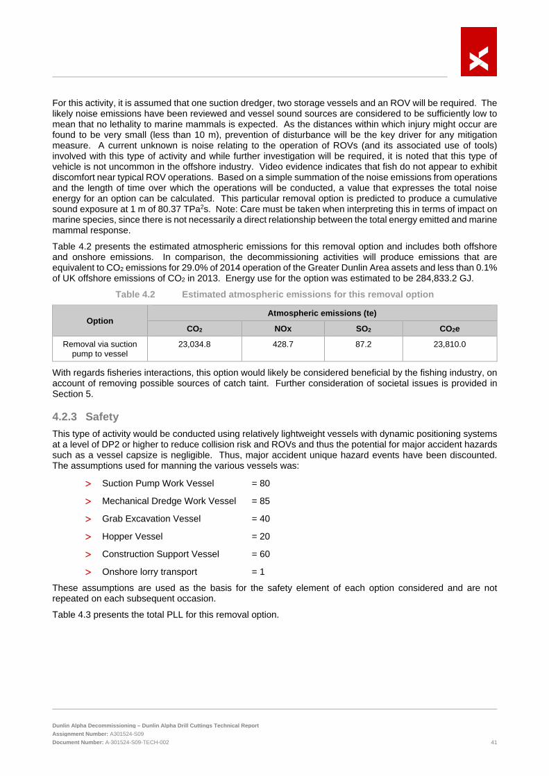
Dunlin Alpha Decommissioning – Dunlin Alpha Drill Cuttings Technical Report Assignment Number: A301524-S09 Document Number: A-301524-S09-TECH-002 41
For this activity, it is assumed that one suction dredger, two storage vessels and an ROV will be required. The likely noise emissions have been reviewed and vessel sound sources are considered to be sufficiently low to mean that no lethality to marine mammals is expected. As the distances within which injury might occur are found to be very small (less than 10 m), prevention of disturbance will be the key driver for any mitigation measure. A current unknown is noise relating to the operation of ROVs (and its associated use of tools) involved with this type of activity and while further investigation will be required, it is noted that this type of vehicle is not uncommon in the offshore industry. Video evidence indicates that fish do not appear to exhibit discomfort near typical ROV operations. Based on a simple summation of the noise emissions from operations and the length of time over which the operations will be conducted, a value that expresses the total noise energy for an option can be calculated. This particular removal option is predicted to produce a cumulative sound exposure at 1 m of 80.37 TPa2s. Note: Care must be taken when interpreting this in terms of impact on marine species, since there is not necessarily a direct relationship between the total energy emitted and marine mammal response.
Table 4.2 presents the estimated atmospheric emissions for this removal option and includes both offshore and onshore emissions. In comparison, the decommissioning activities will produce emissions that are equivalent to CO2 emissions for 29.0% of 2014 operation of the Greater Dunlin Area assets and less than 0.1% of UK offshore emissions of CO2 in 2013. Energy use for the option was estimated to be 284,833.2 GJ.
Table 4.2 Estimated atmospheric emissions for this removal option
Option Atmospheric emissions (te)
CO2 NOx SO2 CO2e
Removal via suction pump to vessel
23,034.8 428.7 87.2 23,810.0
With regards fisheries interactions, this option would likely be considered beneficial by the fishing industry, on account of removing possible sources of catch taint. Further consideration of societal issues is provided in Section 5.
4.2.3 Safety This type of activity would be conducted using relatively lightweight vessels with dynamic positioning systems at a level of DP2 or higher to reduce collision risk and ROVs and thus the potential for major accident hazards such as a vessel capsize is negligible. Thus, major accident unique hazard events have been discounted. The assumptions used for manning the various vessels was:
> Suction Pump Work Vessel = 80
> Mechanical Dredge Work Vessel = 85
> Grab Excavation Vessel = 40
> Hopper Vessel = 20
> Construction Support Vessel = 60
> Onshore lorry transport = 1
These assumptions are used as the basis for the safety element of each option considered and are not repeated on each subsequent occasion.
Table 4.3 presents the total PLL for this removal option.

Dunlin Alpha Decommissioning – Dunlin Alpha Drill Cuttings Technical Report Assignment Number: A301524-S09 Document Number: A-301524-S09-TECH-002 42
Table 4.3 Estimated exposure hours and PLLs for this removal option
Vessel requirement
Main Work Vessel/Platform (Persons on board) Construction Support Vessel (80)
Days 134
Main Work Vessel (PLLx10e-3) 9.65
Hopper Vessel Days 166
Hopper (PLLx10e-3) 2.99
Debris removal / Survey (provided in days) 0
Debris removal / Survey (PLLx10e-3) 0
Onshore lorry trips (assumed to be 150 km round trip) 8,079
Lorry (PLLx10e-3) 2.26
Total PLL x 10e-3 14.9
4.2.4 Cost The cost of the full cuttings removal for this option is presented in Table 4.4. The duration of each activity was derived by expert engineering opinion based upon the available information at the time of writing the report.
Table 4.4 Option 1: Cuttings removal costs
Activity Unit cost Quantity Cost (£m)
Drill Cuttings Clearance
(Including 10% waiting on weather allowance)
0.09 £m/day
134 days 12.060
Transport of Drill Cuttings
(Including 10% waiting on weather allowance)
0.03 £m/day
83 days 2.490
Decommissioning Contractors Engineering and Management 10% of total cost
1 1.455
Total 16.005
4.3 Option 2 - Remove via mechanical dredging
4.3.1 Technical Mechanical dredging is typically required if the seabed material is dense, consolidated or stratified and needs to be cut up or broken up prior to being transported to the surface. Recovery to the surface can either be done by mechanical systems or by subsea pumping – if subsea pumping is used then the technology and techniques are generally very similar to the suction pumping option but with the addition of the mechanical systems to break up consolidated seabed material.
Although technology such as the cutting suction dredging vessel as shown in Figure 4.6, is available in the current market, it is understood to be limited to water depths of around 70 m or less. The use of tracked ROV dredging systems is reasonably well known in the oil and gas industry and they have a proven track record. These systems have been operated at depths of up to 300 m, although in such cases the debris was typically redistributed on the seabed rather than recovered to the surface. Therefore, further significant development would be needed to adapt the equipment to the water depths at the Dunlin Alpha particularly the pumping system.

Dunlin Alpha Decommissioning – Dunlin Alpha Drill Cuttings Technical Report Assignment Number: A301524-S09 Document Number: A-301524-S09-TECH-002 43
Subsea mechanical dredging can be typically carried out by a tracked type ROV with a positive displacement pump to recover the drill cuttings to surface. In most cases these systems use mechanical tooling to break up the seabed material so that it can be fluidised by the sea water flowing through the dredge pump and then recovered using the suction pump. The tracks would be required to support the additional weight of the mechanical systems required to break up the seabed and to provide a stable working platform for them. Another type of system for breaking up harder seabed materials consists of a heavy duty ROV system but additionally fitted with a high-pressure water jet skid that can be directed at the hard materials to be dredged to break them up for the dredging and pumping systems to fluidise them. These types of equipment would usually be deployed from a construction support vessel (CSV). However, as these vessels typically don’t have suitable storage facilities for the received material, an additional vessel or vessels would be required to receive and transport the cuttings and water recovered.
Figure 4.6 Mechanical cutting suction dredging vessel
4.3.2 Environmental and societal Direct physical disturbance of the cuttings pile may occur as part of any mechanical or water-jetting that might be necessary to disaggregate cuttings that have become compacted over time, prior to sucking these up to the surface. Physical disturbance of the cuttings, with the raising of sediment plumes and associated hydrocarbon contamination was modelled Under Option 1 (Section 4.2) and the reader is referred to that section for details.
For consideration of noise, this option assumes the use of one mechanical dredger, two storage vessels and the use of an ROV. Vessel sound sources are sufficiently low to mean that no lethality to marine mammals is expected. As distances within which injury might occur are found to be very small (less than 10 m), prevention of disturbance will be the key driver for any mitigation measure. A current unknown is noise relating to the operation of ROVs (and its associated use of tools) involved with this type of activity and while further investigation will be required, it is noted that this type of vehicle is not uncommon in the offshore industry. Video evidence indicates that fish do not appear to exhibit discomfort near typical ROV operations. In terms of total noise emissions, this removal option is predicted to produce a cumulative sound exposure at 1 m of 42.36 TPa2s. Note: Care must be taken when interpreting this in terms of impact on marine species, since there is not necessarily a direct relationship between the total energy emitted and marine mammal response.
Table 4.5 presents the estimated atmospheric emissions for this removal option and includes both offshore and onshore emissions. In comparison, the decommissioning activities will produce emissions that are equivalent to CO2 emissions for 32.7% of 2014 operation of the Greater Dunlin Area assets and 0.1% of UK offshore emissions of CO2 in 2013. Energy use for the option was estimated to be 316,226.6 GJ.

Dunlin Alpha Decommissioning – Dunlin Alpha Drill Cuttings Technical Report Assignment Number: A301524-S09 Document Number: A-301524-S09-TECH-002 44
Table 4.5 Estimated atmospheric emissions for this removal option
Option Atmospheric emissions (te)
CO2 NOx SO2 CO2e
Removal via mechanical dredging
25,918.0 482.4 98.1 26,790.3
4.3.3 Safety This type of activity would be conducted using relatively lightweight vessels with dynamic positioning systems at a level of DP2 or higher to reduce collision risk and ROVs and thus the potential for major accident hazards such as a vessel capsize is negligible. Major accident unique hazard events have therefore been discounted. Table 4.5 presents the total PLL for this removal option.
Table 4.6 Estimated exposure hours and PLLs for this removal option
Mechanical Dredge
Main Work Vessel/Platform (Persons on board) CSV (85)
Days 121
Main Work Vessel (PLLx10e-3) 9.26
Hopper Vessel Days 212
Hopper (PLLx10e-3) 3.82
Debris removal / Survey (provided in days) 0
Debris removal / Survey (PLLx10e-3) 0
Onshore lorry trips (assumed to be 150 km round trip) 10,305
Lorry (PLLx10e-3) 2.89
Total PLL x 10e-3 15.97
4.3.4 Cost The cost of the full cuttings removal for this option is presented in Table 4.7. The duration of each activity was derived by expert engineering opinion based upon the available information at the time of writing the report.
Table 4.7 Option 2: Cuttings removal costs
Activity Unit cost Quantity Cost (£m)
Drill Cuttings Clearance
(Including 10% waiting on weather allowance)
0.10 £m/day
121 days 12.100
Transport of Drill Cuttings
(Including 10% waiting on weather allowance)
0.03 £m/day
106 days 3.180
Decommissioning Contractors Engineering and Management 10% of total cost
1 1.528
Total 16.808

Dunlin Alpha Decommissioning – Dunlin Alpha Drill Cuttings Technical Report Assignment Number: A301524-S09 Document Number: A-301524-S09-TECH-002 45
4.4 Option 3 - Remove via grab excavation
4.4.1 Technical The grab excavation method typically uses a specialist surface vessel to deploy a clamshell bucket grab tool to excavate materials from the seabed. The tool is typically mechanically or hydraulically controlled directly from the vessel or can be integrated with basic ROV functionality for more accurate control.
This type of technology is commonly used for seabed dredging and for excavating the seabed to create holes. The material recovered by the grab is most commonly relocated subsea but can be recovered to the surface into vessel hoppers. The grabber is typically deployed in relatively shallow water but is believed to be technically feasible for use in deeper water environments.
Although this method has not been documented as having been used for the removal of drill cuttings from the seabed, it is believed that the technology could be adapted for use in this application. The clamshell grab tools are typically a bespoke design specifically for the intended use and are deployed from a vessel using the vessel crane or a dedicated deployment system. For this reason, it is difficult to determine the current availability of this type of tooling and how useful or applicable it might be.
Developing a bespoke design for the grab provides the opportunity to develop the system to ensure that the clamshells are sealed before it leaves the seabed to minimise the loss of drill cuttings or sediment as the grab travels through the water column to the vessel. The volume of material that these clamshells can be designed to collect varies from 1 m³ to 200 m³.
Figure 4.7 illustrates a grab excavation tool with position keeping and monitoring equipment.
Figure 4.7 Typical bespoke grab excavation system with position control
This tool is equipped with thrusters to aid fine positioning at the seabed and could be fitted with the appropriate sensor technology (cameras, sonar etc.) to allow accurate positioning of the tool for controlled excavation and recovery of the seabed and cell top cuttings piles.

Dunlin Alpha Decommissioning – Dunlin Alpha Drill Cuttings Technical Report Assignment Number: A301524-S09 Document Number: A-301524-S09-TECH-002 46
If the platform topsides and conductors are still in place at the time of removal of the drill cutting pile then the grab system will have restricted access to the pile adjacent to the CGBS and is unlikely to have any access at all to the cuttings on top of the CGBS. The effectiveness and efficiency of the cuttings recovery process using a clamshell grab is also likely to be significantly affected by the size of the grab:
> A large grab will be able to recover more material in a given time but will be harder to control and could potentially be limited in areas where access may be constrained or where fine location control is required, such as close alongside the side of the CGBS and amongst the complex geometry on the CGBS cell tops; and
> A smaller grab will pick up less material with each deployment and hence will be much slower overall but could potentially reach the difficult areas where access is more difficult or constrained.
At this stage, it is assumed that a single bucket size for all cutting recovery operations will be defined following further work to find the optimum balance between recovery capacity and the various access constraints and restrictions identified. These bucket studies could also investigate the feasibility of using configuring the system to use multiple bucket sizes either simultaneously or to allow it to switch between different buckets at site. It is worth highlighting that at some stage the cuttings pile would be reduced to a point that use of the grab will no longer be effective.
4.4.2 Environmental and societal Direct physical disturbance in this option may occur through the landing and biting action of any grab used, and through the release of material from the bucket due to incomplete bucket sealing. Modelling of physical disturbance of the cuttings was not conducted for this option as there is potential for losses to occur throughout the water column; particularly if a previously dropped object becomes caught in the jaws of the grab (i.e. the discharge would occur from a moving position, which available models cannot accurately represent). As such the 10% loss of cutting previously modelled for the suction dredging under Option 1 (Section 4.2) would be expected to be the minimum seen for the grab excavation case assuming no additional losses other than those near the seabed.
This option is assumed to use one construction support vessel and the use of an ROV. Vessel sound sources are sufficiently low to mean that no lethality to marine mammals is expected. As the distances within which injury might occur are found to be very small (less than 10 m), prevention of disturbance will be the key driver for any mitigation measure. A current unknown is noise relating to the operation of ROVs (and its associated use of tools) involved with this type of activity and while further investigation will be required, it is noted that this type of vehicle is not uncommon in the offshore industry. Video evidence indicates that fish do not appear to exhibit discomfort near typical ROV operations. In terms of total noise emissions, this removal option is predicted to produce a cumulative sound exposure at 1 m of 38.75 TPa2s. Note: Care must be taken when interpreting this in terms of impact on marine species, since there is not necessarily a direct relationship between the total energy emitted and marine mammal response.
Table 4.8 presents the estimated atmospheric emissions for this removal option and include offshore and onshore emissions. In comparison, the decommissioning activities will produce emissions that are equivalent to CO2 emissions for 8.3% of 2014 operation of the Greater Dunlin Area assets and much less than 0.1% of UK offshore emissions of CO2 in 2013. Energy use for this option was estimated to be 83,526.9 GJ.
Table 4.8 Estimated atmospheric emissions for this removal option
Option Atmospheric emissions (te)
CO2 NOx SO2 CO2e
Removal via grab excavation 6,620.2 123.2 25.1 6.843.0
With regards to fisheries interactions, this option would likely be considered beneficial by the fishing industry, on account of removing possible sources of catch and net taint. Further consideration of societal issues is provided in Section 5.

Dunlin Alpha Decommissioning – Dunlin Alpha Drill Cuttings Technical Report Assignment Number: A301524-S09 Document Number: A-301524-S09-TECH-002 47
4.4.3 Safety This type of activity would be conducted using relatively lightweight vessels and ROVs and thus the potential for major accident hazards such as a vessel capsize is negligible. Thus, major accident unique hazard events have been discounted. Table 4.7 presents the total PLL for this removal option.
Table 4.9 Estimated exposure hours and PLLs for this removal option
Grab excavation
Main Work Vessel/Platform (Persons on board ) Hopper vessel (40)
Days 46
Main Work Vessel (PLLx10e-3) 1.66
Hopper Vessel Days 84
Hopper (PLLx10e-3) 1.51
Debris removal / Survey (provided in days) 42
Debris removal / Survey (PLLx10e-3) 1.59
Onshore lorry trips (assumed to be 150 km round trip) 2,804
Lorry (PLLx10e-3) 0.79
Total PLL x 10e-3 5.55
4.4.4 Cost The cost of the full cuttings removal for this option is presented in Table 4.10.
Table 4.10 Option 3: Cuttings removal costs
Activity Unit cost Quantity Cost (£m)
Drill Cuttings Clearance
(Including 10% waiting on weather allowance)
0.06 £m/day
46 days 2.760
CSV Support
(Including 10% waiting on weather allowance)
0.05 £m/day
42 days 2.100
Decommissioning Contractors Engineering and Management 10% of total cost
1 0.486
Total 5.346
4.5 Option 4 - Remove via suction pumping dredging to platform
4.5.1 Technical Considering the suction pump dredging system outlined for the option to remove via suction pump to a vessel in Section 4.1, an alternative to hosting the subsea suction system from a CSV could be to deploy it from the Dunlin Alpha itself, or even from a jack up rig positioned alongside the platform.
Surface operated equipment is typically the cheapest to run and maintain but has the restriction of usually being water depth dependent. Subsea operations are typically limited to the use of an ROV due to the risk to a diver associated with using mechanical cutting systems and the hazardous substances contained within the cuttings pile.

Dunlin Alpha Decommissioning – Dunlin Alpha Drill Cuttings Technical Report Assignment Number: A301524-S09 Document Number: A-301524-S09-TECH-002 48
An example of the platform pump dredging is shown in Figure 4.8 below. Note, Figure 4.8 illustrates the Riser Mud Recovery (RMR) system; however, the hose connection between the riser and subsea pump is of ROV make up and could be easily adapted to allow connection to a work class ROV (WROV) to use the hose end for dredging. The subsea operated suction pumping method is carried out by an ROV based dredging system which includes a lift pipe and a subsea pump. The ROV is fitted with a suction hose head to recover the cuttings from the seabed where a lift pipe connected to the exhaust vent of the ROV dredge allows the cuttings to be pumped to the surface and creates a closed dredging system. The additional subsea pump is used to aid the recovery of the drill cuttings to the surface and into the platform/vessel storage tanks.
Figure 4.8 Platform based suction pump system
Another similar system, the Oceaneering ROV Dredging system has documented that that it can dredge 100-200 m³/hour and can work up to depths of 2,000 m.
The ROV dredging system should be equipped to perform a range of ROV-based subsea construction and decommissioning activities. Using the Dunlin Alpha as a host gives the potential to use the existing platform drill cuttings, fluid separation and water treatment facilities to treat the recovered cuttings slurry so the seawater can be disposed of to sea. This would then leave the dewatered drill cuttings to be packaged at the platform for transportation onshore for treatment and disposal. This option would require around 5 to 6 months to complete.
4.5.2 Environmental and societal Physical disturbance of the cuttings, with the raising of sediment plumes and associated hydrocarbon contamination, is assumed to be identical to the disturbance involved in Option 1. Therefore, the reader is referred to the modelling inputs and results presented in Sections 4.2 respectively. Modelling predicted water column and seabed impacts to be transient and small-scale with limited impact to the benthic community.
This option is assumed to take place from the Dunlin Alpha platform and require two support vessels and the use of an ROV. Vessel sound sources are sufficiently low to mean that no lethality to marine mammals is expected. As the distances within which injury might occur are found to be very small (less than 10 m), prevention of disturbance will be the key driver for any mitigation measure. A current unknown is noise relating to the operation of ROVs (and its associated use of tools) involved with this type of activity and while further
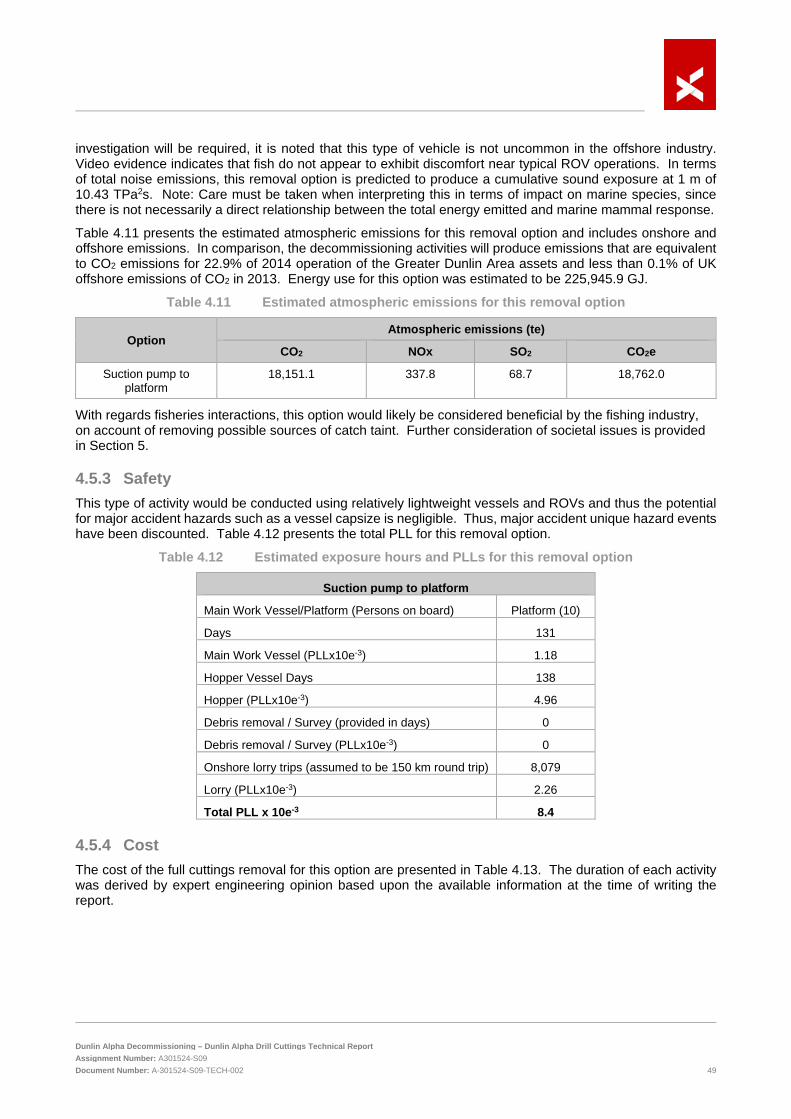
Dunlin Alpha Decommissioning – Dunlin Alpha Drill Cuttings Technical Report Assignment Number: A301524-S09 Document Number: A-301524-S09-TECH-002 49
investigation will be required, it is noted that this type of vehicle is not uncommon in the offshore industry. Video evidence indicates that fish do not appear to exhibit discomfort near typical ROV operations. In terms of total noise emissions, this removal option is predicted to produce a cumulative sound exposure at 1 m of 10.43 TPa2s. Note: Care must be taken when interpreting this in terms of impact on marine species, since there is not necessarily a direct relationship between the total energy emitted and marine mammal response.
Table 4.11 presents the estimated atmospheric emissions for this removal option and includes onshore and offshore emissions. In comparison, the decommissioning activities will produce emissions that are equivalent to CO2 emissions for 22.9% of 2014 operation of the Greater Dunlin Area assets and less than 0.1% of UK offshore emissions of CO2 in 2013. Energy use for this option was estimated to be 225,945.9 GJ.
Table 4.11 Estimated atmospheric emissions for this removal option
Option Atmospheric emissions (te)
CO2 NOx SO2 CO2e
Suction pump to platform
18,151.1 337.8 68.7 18,762.0
With regards fisheries interactions, this option would likely be considered beneficial by the fishing industry, on account of removing possible sources of catch taint. Further consideration of societal issues is provided in Section 5.
4.5.3 Safety This type of activity would be conducted using relatively lightweight vessels and ROVs and thus the potential for major accident hazards such as a vessel capsize is negligible. Thus, major accident unique hazard events have been discounted. Table 4.12 presents the total PLL for this removal option.
Table 4.12 Estimated exposure hours and PLLs for this removal option
Suction pump to platform
Main Work Vessel/Platform (Persons on board) Platform (10)
Days 131
Main Work Vessel (PLLx10e-3) 1.18
Hopper Vessel Days 138
Hopper (PLLx10e-3) 4.96
Debris removal / Survey (provided in days) 0
Debris removal / Survey (PLLx10e-3) 0
Onshore lorry trips (assumed to be 150 km round trip) 8,079
Lorry (PLLx10e-3) 2.26
Total PLL x 10e-3 8.4
4.5.4 Cost The cost of the full cuttings removal for this option are presented in Table 4.13. The duration of each activity was derived by expert engineering opinion based upon the available information at the time of writing the report.

Dunlin Alpha Decommissioning – Dunlin Alpha Drill Cuttings Technical Report Assignment Number: A301524-S09 Document Number: A-301524-S09-TECH-002 50
Table 4.13 Option 4: Cuttings removal costs
Activity Unit cost
Quantity Cost (£m)
Platform Drill Cuttings Clearance
(Including 10% waiting on weather allowance)
0.005 £m/day
131 days 0.655
Transport of Drill Cuttings
(Including 10% waiting on weather allowance)
0.03 £m/day
119 days 3.570
Decommissioning Contractors Engineering and Management 10% of total cost
1 0.423
Total 4.648
4.6 Option 5 - Redistribute via suction pumping dredging seabed dispersal
4.6.1 Technical As an alternative to recovering the cuttings to the surface for treatment and disposal, it may also be possible to move the cuttings pile to other seabed locations and at the same time to disperse the material within them over a wider area, thus accelerating the breakdown of toxic materials.
Subsea dispersal dredging can be achieved using technologies similar to the Cutting Transporting System (CTS) which has documented that it is possible to pump the cuttings up to 2 km away from the CGBS (Figure 4.9). These systems typically use mechanical tooling to break up the seabed material so that it can be fluidised by the sea water flowing through the dredge pump. This type of equipment would typically be deployed from a CSV.
It should be possible to relocate the discharge pipe periodically by ROV to disperse the cuttings in a thin layer over a wider area.
Figure 4.9 Platform based suction pump dredging – seabed dispersal
The assumption in this report is that the cuttings are dispersed evenly across the southern half of the Dunlin Alpha 500 m safety exclusion zone. Subtracting the area covered by the Dunlin CGBS, the exclusion zone is calculated to have an area of 774,184 m2, and half of this amounts to 387,092 m2. An even distribution of the

Dunlin Alpha Decommissioning – Dunlin Alpha Drill Cuttings Technical Report Assignment Number: A301524-S09 Document Number: A-301524-S09-TECH-002 51
full cuttings volume across this area would give an average cuttings deposition thickness of approximately 5 cm.
An ROV support vessel with at least two WROV systems, crane, deck capacity, ROV tooling suitable for debris handling and general ROV support operations will be required. Such vessels would typically be at least DP2. Typical sea-state limitation would be a significant wave height of 3.5 m.
Depending on the expected time required infield, a supply vessel may be required for providing fuel, provisions, water and spares to the infield vessels. Typical sea-state limitation would be a significant wave height of 1 m for vessel to vessel transfer operations.
4.6.2 Environmental and societal There are two principal pathways in which suction dredging and redistribution of material over the seabed can have an impact on the environment. These are:
> Pathway 1 – Material that is suspended by the suction dredging activities, but not removed by the suction equipment and therefore released to the water column at the dredge location; and
> Pathway 2 – Material that is removed from the pile and discharged from the discharge pipes located 1 km from the cuttings pile.
Pathway 1 is discussed in Section 4.2 as an effect of Option 1 and results are not repeated in this section. To understand the environmental impact of Pathway 2, modelling was performed using the same model as used for Pathway 1. Two scenarios were modelled:
> Suction Redistribution Scenario 1 – assumes that the entire pile is redistributed; and
> Suction Redistribution Scenario 2 – assumes that only the part of the pile that is located on the CGBS is redistributed.
For Scenario 1 (entire cuttings pile redistribution), the cuttings pile was simplified and assumed to have three layers as detailed in Section 4.2.2. For Scenario 2 (cell top cuttings pile only redistribution), the cuttings pile was also simplified and assumed to have three layers, but the heavy metal content of the cuttings, barite and bentonite and the mass of hydrocarbons was assessed using maximum values from survey data from the cell top cuttings pile only.
For both scenarios, it is assumed that eight locations will be used to pump dredged material in an arc 1 km to the south of the cuttings pile. At each location, the discharge is as follows: an eighth of Layer 1, then pause for 12 hours, then discharge an eighth of Layer 2, then pause for 12 hours, and finally discharge an eighth of Layer 3. The composition and mass of each layer is given in Table 4.14 and Table 4.15. Each discharge port is directed horizontally to the south and has a diameter of 0.216 m. The discharge rate of water plus dredged material for each cuttings transport system is assumed to be 150 m3/hour, and with a water: solid ratio of 15:1 (UKOOA, 2002) this results in a discharge of 23.4 te dredged material per hour. It is assumed from a cost perspective a single cuttings relocation device would be repositioned to each location after one eighth of the cuttings material had been discharged (this process is compressed within the model). As previous cuttings pile modelling demonstrated that the water column impact lasted for slightly longer than the period of discharge, this simulation specifically investigated the impact on the seabed.

Dunlin Alpha Decommissioning – Dunlin Alpha Drill Cuttings Technical Report Assignment Number: A301524-S09 Document Number: A-301524-S09-TECH-002 52
Table 4.14 Total masses and concentrations used in suction redistribution Option 5 scenario 1 entire cuttings pile
Parameter Layer 1 Layer 2 Layer 3
Water:solid ratio 15:1 15:1 15:1
Discharge height above seabed (m)
4 4 4
Mass of solid material discharged in total by all cuttings transport systems
Cuttings (te) 2,110 19,000 19,600
Barite (te) 504 4,540 1,260
Bentonite (te) 82.9 746 1,040
Total particulate material (te) 2,700 24,300 21,900
Total particulates and water discharged (te)
40,500 365,000 328,000
Mass of hydrocarbons discharged in total by all cuttings transport systems
Total hydrocarbons (te) 394 2,770
None AP/APEs (te) 0.0107 5.49
BPA (te) 0.000378 0.00263
Concentration of heavy metals
Cd (ppm) 3.21 3.58
Cr (ppm) 113 38.2
Cu (ppm) 338 96.0
Hg (ppm) 1.23 1.39
Pb (ppm) 188 197
Zn (ppm) 3,930 1,560

Dunlin Alpha Decommissioning – Dunlin Alpha Drill Cuttings Technical Report Assignment Number: A301524-S09 Document Number: A-301524-S09-TECH-002 53
Table 4.15 Total masses and concentrations used in suction redistribution Option 5 scenario 2 CBGS roof cuttings pile
Parameter Layer 1 Layer 2 Layer 3
Water:solid ratio 15:1 15:1 15:1
Discharge height above seabed (m)
4 4 4
Mass of solid material discharged in total by all cuttings transport systems
Cuttings (te) 1,103 9,920 10,200
Barite (te) 263 2,370 655
Bentonite (te) 43.3 389 542
Total particulate material (te) 1,409 12,682 11,400
Total particulates and water discharged (te)
21,100 190,000 171,000
Mass of hydrocarbons discharged in total by all cuttings transport systems
Total hydrocarbons (te) 198 1,780
None AP/APEs (te) 0.0303 5.49
BPA (te) 7.29E-06 1.70E-04
Concentration of heavy metals
Cd (ppm) 0.870 0.260
Cr (ppm) 44.0 20.0
Cu (ppm) 34.4 52.6
Hg (ppm) 0.990 1.18
Pb (ppm) 52.6 101
Zn (ppm) 447 807 Sediment thickness for Suction Redistribution Scenario 1 is shown in Figure 4.10. The model predicts that sediment would accumulate with an average maximum thickness of 1.07 m at each discharge location, reducing to less than 10 mm within 1.30 km and 1 mm within 3.5 km of the nearest discharge location.
The environmental impact on the sediment is predicted to be moderate to high, with a maximum impact equivalent to an impact on greater than 5% of benthic organisms over an area of 6.31 km2, this was predicted to decrease to 1.45 km2 after 25 years. The main contributors to this are the zinc and mercury content of the cuttings, which contribute 50% of the risk in total (Figure 4.11).

Dunlin Alpha Decommissioning – Dunlin Alpha Drill Cuttings Technical Report Assignment Number: A301524-S09 Document Number: A-301524-S09-TECH-002 54
Figure 4.10 Predicted sediment thickness for suction redistribution scenario 1 – relocation of the
entire cuttings pile
Figure 4.11 Contributions of contaminants to the sediment impact for scenario 1– relocation of
the entire cuttings pile

Dunlin Alpha Decommissioning – Dunlin Alpha Drill Cuttings Technical Report Assignment Number: A301524-S09 Document Number: A-301524-S09-TECH-002 55
Sediment thickness for Suction Redistribution Scenario 2 is shown in Figure 4.12. The model predicts that sediment would accumulate with an average maximum thickness of 0.56 m at each discharge location, reducing to less than 10 mm within 1.40 km and 1 mm within 3.8 km of the nearest discharge location.
Figure 4.12 Predicted sediment thickness for suction redistribution scenario 2 – relocation of the
cell roof cuttings pile The environmental impact on the sediment is predicted to be moderate, with a maximum impact equivalent to an impact on greater than 5% of benthic organisms over an area of 1.84 km2, decreasing to 0.64 km2 after 25 years. The main contributors to this are the zinc and mercury content of the cuttings and changes in the sediment grain size, which contribute 64% of the risk in total (Figure 4.12).
Figure 4.13 Contributions of contaminants to the sediment impact for suction redistribution
scenario 2 – relocation of the cell roof cuttings pile

Dunlin Alpha Decommissioning – Dunlin Alpha Drill Cuttings Technical Report Assignment Number: A301524-S09 Document Number: A-301524-S09-TECH-002 56
In terms of noise emissions, it has been assumed that one suction dredger and an ROV will be used. Vessel sound sources are sufficiently low to mean that no lethality to marine mammals is expected, and as the distances within which injury might occur are found to be very small (less than 10 m), prevention of disturbance will be the key driver for any mitigation measure. A current unknown is noise relating to the operation of ROVs (and its associated use of tools) involved with this type of activity and while further investigation will be required, it is noted that this type of vehicle is not uncommon in the offshore industry. Video evidence indicates that fish do not appear to exhibit discomfort near typical ROV operations. In terms of total noise emissions, this redistribution option is predicted to produce a cumulative sound exposure at 1 m of 73.15 TPa2s. Note: Care must be taken when interpreting this in terms of impact on marine species, since there is not necessarily a direct relationship between the total energy emitted and marine mammal response.
The end-point for this evaluation does not involve reprocessing and therefore there are no additional onshore atmospheric emissions to be considered or indeed any potential for the transboundary shipment of waste. Table 4.16 presents the estimated atmospheric emissions for this redistribution option. In comparison, the decommissioning activities will produce emissions that are equivalent to CO2 emissions for 11.8% of 2014 operation of the Greater Dunlin Area assets and much less than 0.1% of UK offshore emissions of CO2 in 2013. Energy use for this option was estimated to be 127,058.80 GJ.
Table 4.16 Estimated atmospheric emissions for this redistribution option
Option Atmospheric emissions (te)
CO2 NOx SO2 CO2e
Redistribution via suction pump
9,345.2 173.9 35.4 9,659.7
With regards fisheries interactions, this option would likely be considered by the fishing industry to be negative on balance. Whilst it will disperse cuttings and speed up overall degradation time, cuttings will be redistributed up to approximately 3.8 km from the discharge points. Given the potential tainting of catch and contamination of gear that could result from demersal fishing within those areas, it is possible that fishing activity may avoid such areas, thus limiting the overall available fishing area. The type of restriction that could occur (e.g. geographic, gear, species-specific) and its duration would likely be determined by biological monitoring following any documented tainting. Based on the spill of oil from the Erica of Brittany (19,800 te of crude lost), if release of contaminants from the dispersed cuttings is documented then demersal and pelagic fisheries closures could last for up to 2 years and be spatially limited, with subsequent restrictions on demersal fishing extending for up to 10 years. Further consideration of societal issues is provided in Section 5.
4.6.3 Safety This type of activity would be conducted using relatively lightweight vessels and ROVs and thus the potential for major accident hazards such as a vessel capsize is negligible. Thus, major accident unique hazard events have been discounted. Table 4.13 presents the total PLL for this redistribution option.
Note: To be legally able to redistribute cuttings on the seabed a Marine Licence would be required. The application for this would need to include an impact assessment to quantify the amount of disturbance. It is likely that a similar requirement would be applied as those for contaminated dredged material from ports and harbours, whereby demonstration that the sediment contamination is low and does not pose a risk to the environment would be required before disposal at sea is permitted. In addition, the acceptability of this option to other users of the sea notably fishermen is likely to be very low.

Dunlin Alpha Decommissioning – Dunlin Alpha Drill Cuttings Technical Report Assignment Number: A301524-S09 Document Number: A-301524-S09-TECH-002 57
Table 4.17 Estimated exposure hours and PLLs for this redistribution option
Suction pump seabed dispersal
Main Work Vessel/Platform (Persons on board) CSV (80)
Days 134
Main Work Vessel (PLLx10e-3) 9.65
Hopper Vessel Days 0
Hopper (PLLx10e-3) 0
Debris removal / Survey (provided in days) 0
Debris removal / Survey (PLLx10e-3) 0
Onshore lorry trips (assumed to be 150 km round trip) 0
Lorry (PLLx10e-3) 0
Total PLL x 10e-3 9.65
4.6.4 Cost The cost of the full cuttings dispersal for this option is presented in Table 4.18. The duration of each activity was derived by expert engineering opinion based upon the available information at the time of writing the report.
Table 4.18 Option 5: Cuttings removal costs
Activity Unit cost Quantity Cost (£m)
Drill Cuttings Clearance
(Including 10% waiting on weather allowance)
0.09 £m/day 134 days 12.060
Decommissioning Contractors Engineering and Management 10% of total cost
1 1.206
Total 13.266
4.7 Option 6 - Leave in situ
4.7.1 Technical Should the selected decommissioning option for the Dunlin Alpha platform require no disturbance of the cuttings pile, no preparation of the cuttings pile would be required for the leave in situ option apart from the removal of easily accessible debris.
4.7.2 Environmental and societal One scenario was considered for modelling of the leave in situ option (details of the current condition of the cuttings pile are given in Section 3 and are not repeated here). This was over-trawling releasing hydrocarbons from the pile which is the principal release pathway for cuttings pile contaminants to the marine environment if the cuttings pile is left in situ without management. Water column impacts from deliberate over trawling trials as part of the decommissioning process are expected to be localised and short lived and were therefore not considered by the model.
To evaluate the impact from future fishing interaction, modelling has been performed on 10% of the entire cuttings pile being disturbed in an single over-trawl event (4,890 te), and that this pile would have the composition of Layer 1 as described in Section 4.2.2 and Table 4.14. Discharge would occur over one hour.

Dunlin Alpha Decommissioning – Dunlin Alpha Drill Cuttings Technical Report Assignment Number: A301524-S09 Document Number: A-301524-S09-TECH-002 58
Sediment thickness for the over-trawl event is shown in Figure 4.14. The model predicts that sediment would accumulate with a maximum thickness of 0.43 m at the discharge location, reducing to less than 10 mm within 2.9 km and 1 mm within 11.7 km of the cuttings pile.
The environmental impact on the sediment is predicted to be moderate, with a maximum impact equivalent to an impact on greater than 5% of benthic organisms over an area of 2.07 km2, decreasing to 0.35 km2 after 25 years. The main contributor to this is the zinc content of the cuttings, which contributes 53% of the risk in total (Figure 4.15).
Figure 4.14 Predicted sediment thickness for an over-trawl event

Dunlin Alpha Decommissioning – Dunlin Alpha Drill Cuttings Technical Report Assignment Number: A301524-S09 Document Number: A-301524-S09-TECH-002 59
Figure 4.15 Contributions of contaminants to the sediment impacts for a trawl event
There are no activities associated with this option and therefore underwater noise and atmospheric emissions do not require assessment.
It is noted that leaving the cuttings pile in situ has the potential to pose a risk to fisheries, particularly in terms of possible tainting of catch and nets should trawling take place over the edge of the cuttings pile. Further consideration of societal issues is provided in Section 5.
4.7.3 Safety As there are no activities planned for this option there are no potential safety aspects anticipated with respect to the decommissioning of the pile itself. However, for the cuttings pile to be left in situ, this would require the CGBS decommissioning option to require it to remain in situ as well. Therefore, in line with regulatory requirements Fairfield must ensure that the position (horizontal datum to be stated), surveyed depth and dimensions of the CGBS are notified to the Hydrographic Office, for inclusion on Admiralty charts. Details of the action to be taken to advise mariners and mark any remains should be included in the Decommissioning Programme, notably by marking them on the FishSafe system and through notices to mariners at the end of decommissioning following removal of the safety zone; and this is likely to be via SeaFish FishSafe with the Hydrographic Office being kept informed. Drill cuttings accumulations themselves would only be marked on Admiralty charts if it is considered that they present a danger to surface navigation or alter the charted seabed depth significantly, neither of which are likely for the Dunlin cuttings pile.
Each technological option assessed in the previous sections has a proven track record in their own current markets of operation and are considered likely to be capable of removing or relocating the drill cuttings from the seabed and CGBS. However, it is considered that they would all need significant further development to adapt their equipment and systems to handle the necessary volumes of drill cuttings and to process hydrocarbons and other materials which they contain.
Furthermore, it needs to be highlighted that during this study no estimate has been made regarding the following critical issues that are likely to have an impact on the feasibility and effectiveness of each methodology:
> No assessment has been made of the effectiveness of the proposed recovery options in removing all of the cuttings pile material – there are no data available;
> No assessment has been made of the proportion of solids recovered to those lost in the recovery process and the quantity lost to the water column during recovery operations;

Dunlin Alpha Decommissioning – Dunlin Alpha Drill Cuttings Technical Report Assignment Number: A301524-S09 Document Number: A-301524-S09-TECH-002 60
> No assessment has been made of the extent of contamination of water recovered – water is assumed to be contaminated to similar extent as drill cuttings and hence is not suitable for over side disposal; and
> No in-depth assessment into the suitability of hopper vessels for the storage, transportation, handling and disposal of combined cuttings and sea water slurry.
It should also be noted that the solid to liquid recovery ratios are an estimate. Table 4.16 - 4.19 summarise the quantitative values used to assess the environmental and safety impacts of the six cuttings pile management options. The assessment of options is discussed in Section 5.
4.7.4 Cost No additional costs are expected for the leave in situ option for cuttings pile management as no additional activities are required.
4.8 Summary A tabular summary of the above options description and assessment is provided in Tables 4.21 – 4.24. Section 5 further evaluates the options on a technical, safety, environmental, societal and economic basis: Table 5.1 summarises the outcome of the weighted analysis for each option.
Table 4.19 Modelling results summary
Parameter Max thickness (m)
Area of initial impact (ha)
Area impacted after 25 years (ha) Option relevance
Resuspension of 10% of total pile
1.03 0.37 0.10 All options involving suction pumping (Options 1, 2, 4, 5)
Resuspension of 10% of CGBS pile
0.6 0.37 0.10 All options involving suction pumping of CGBS pile only (sub option of Options 1, 2, 4, 5)
Pile redistribution total pile 1.07 6.31 1.45 Option 5
Pile redistribution CGBS pile only
0.56 1.84 0.64 Sub option of Option 5
Trawl interaction causing 10% release comprising surface material
0.43 2.07 0.35 Option 6 and all partial removal sub options
Leave pile in situ 15.1 0.25 - Option 6

Dunlin Alpha Decommissioning – Dunlin Alpha Drill Cuttings Technical Report Assignment Number: A301524-S09 Document Number: A-301524-S09-TECH-002 61
Table 4.20 Comparison of total cumulative source noise (at 1 m) for debris removal across full deconstruction phase (described as sound exposure level (SEL), dB re 1 µPa2s at 1 m)
Noise source Number
of vessels
Total transit and working
days per vessel
Source noise level, SPL
dB re 1 µP @ 1 m (rms)
Cumulative SEL @ 1 m over entire
project
Cumulative sound
exposure @ 1 m (TPa2s)
Option 1: ROV suction dredger with recovery to vessel
Suction dredger 1 134 188 259 73.05
Storage vessel 2 166 174 249 7.21
ROV 1 123 160 230 0.11
Cumulative SEL at 1 m – Option 1 258 80.37
Option 2: ROV mechanical and suction dredging with recovery to vessel
Mechanical and suction dredger 1 121 185 255 33.06
Storage vessel 2 212 174 250 9.20
ROV 1 121 160 230 0.10
Cumulative SEL at 1 m – Option 2 256 42.36
Option 3: Surface-operated clamshell grab with recovery to vessel
Mechanical grab dredger 1 46 186 252 15.82
CSV 1 42 188 254 22.90
ROV 1 36 160 225 0.03
Cumulative SEL at 1 m – Option 3 256 38.75
Option 4: ROV suction dredging with recovery to platform topsides
Platform (transit/set up operations)
1 10 174 233 0.22
Storage vessel 2 233 174 250 10.11
ROV 1 114 160 230 0.10
Cumulative SEL at 1 m – Option 4 250 10.43
Option 5: ROV suction dredging with dispersal over wider seabed
Suction dredger 1 134 188 259 73.05
ROV 1 114 160 230 0.10
Cumulative SEL at 1 m – Option 5 259 73.15
Option 6: leave in situ
Suction dredger 0 0 0 0 0
ROV 0 0 0 0 0
Cumulative SEL at 1 m – Option 6 0 0

Dunlin Alpha Decommissioning – Dunlin Alpha Drill Cuttings Technical Report Assignment Number: A301524-S09 Document Number: A-301524-S09-TECH-002 62
Table 4.21 Estimated atmospheric emissions for each decommissioning option
Parameter Option 1 Option 2 Option 3 Option 4 Option 5 Option 6
Fuel use (t) 7,266.5 8,176.0 2,088.4 5,725.9 2,948.0 0
CO2 (te) 23,034.8 25,918.0 6,620.2 18,151.1 9,345.2 0
NOx (te) 428.7 482.4 123.2 337.8 173.9 0
SO2 (te) 87.2 98.1 25.1 68.7 35.4 0
CO2e (te) 23,810.0 26,790.3 6,843.0 18,762.0 9,659.7 0
% of Dunlin 2014 emissions
29.0 32.7 8.3 22.9 11.8 0
Energy use (GJ) 284,833.2 316,226.6 83,526.9 225,949.9 127,058.80 0
Table 4.22 Estimated exposure hours and PLLs for each decommissioning option
Parameter Option 1 Option 2 Option 3 Option 4 Option 5 Option 6
Main work vessel/platform (persons on board)
CSV (80) CSV (85) Hopper vessel (40)
Platform (10) CSV (80) 0
Days 134 121 46 131 134 0
Main work vessel (PLLx10e-3)
9.65 9.26 1.66 1.18 9.65 0
Hopper vessel days 166 212 84 138 0 0
Hopper (PLLx10e-3) 2.99 3.82 1.51 4.96 0 0
Debris removal / Survey (days)
0 0 42 0 0 0
Debris removal / Survey (PLLx10e-3)
0 0 1.59 0 0 0
Onshore lorry trips (assumed to be 150 km round trip)
8,079 10,305 2,804 8,079 0 0
Lorry (PLLx10e-3) 2.26 2.89 0.79 2.26 0 0
Total PLL x 10e-3 14.9 15.97 5.55 8.4 9.65 0

Dunlin Alpha Decommissioning – Dunlin Alpha Drill Cuttings Technical Report Assignment Number: A301524-S09 Document Number: A-301524-S09-TECH-002 63
5 COMPARISION OF OPTIONS In this discussion, options were assessed against the following main and sub criteria:
> Technical;
o Technical feasibility;
> Safety;
o Total PLL;
> Environmental;
o Marine discharges;
o Marine noise;
o Fuel use;
o Gaseous emissions;
> Societal
o Effects on commercial fisheries;
o Employment arising from option;
o Onshore Infrastructure and communities;
> Economic;
o Cost.
Technical Issues associated with the six options were highlighted during the evaluation. Key issues and technology gaps for dredging options are the provision of continuous pumping from seabed dredge tool to surface from 151 m water depth and the identification of suitable tooling/vessels, handling/transfer of slurry between vessels at surface and dealing with contaminated water. For grab excavation, the key issues are grab and grab handling system design, identifying a suitable host vessel and then integrating the grab handling system with the vessel.
General issues were also identified, including those surrounding confirmation of drill cutting pile properties and debris content, handling throughput of the proposed cuttings recovery systems, percentage recovery ratios, cuttings materials lost during recovery process and vessel requirements for handling recovered cuttings
Safety In terms of offshore safety exposure risks (focusing on potential loss of life), the option for leaving in situ presented no risk, followed by grab excavation (Option 3), with Option 4 close thereafter. By comparison, Option 1 using the suction pump and Option 2 using the mechanical dredge, present three times the risk.
Environmental In terms of impact to the seabed and water column, it was apparent that the impacts are broadly comparable. Most of the impact, in terms of plumes generated and the re-settlement of any released contaminants (chiefly hydrocarbons and metals) would remain within the area already affected by the original cuttings discharges, except for Option 5 which specifically re-distributes cuttings across the seabed.
In terms of underwater noise, mainly from the vessels involved in removal activities, no lethal or injury impacts are anticipated. Options 2, 3 and 4 are similar in terms of overall cumulative noise sound exposure. Option 1 the suction dredger is marginally higher due to the source data assumed for suction dredging operations
The option with the highest estimated energy demand is Option 2 (316,067.9 Gj), which is comparable with Option 1 (284,708.8 Gj, 90% of Option 2) and Option 4 (225,854.5 Gj, 71.4% of Option 2. Option 6 carries the lowest energy demand of 0 Gj, followed by Option 3 (83,500 Gj, 26.4% of Option 2).

Dunlin Alpha Decommissioning – Dunlin Alpha Drill Cuttings Technical Report Assignment Number: A301524-S09 Document Number: A-301524-S09-TECH-002 64
The total CO2 equivalent emissions from Options 1 and 2 were similar at 23,082 te and 25,862 te respectively. Emissions from Option 3 were much less, at approximately 6,677 te. There are no CO2 equivalent emissions associated with Option 6.
Societal The duration of the dredging of the total cuttings pile offshore is a short-term activity with an estimate of between 46 and 134 days for the five remediation options (depending on methodology). It is estimated to provide temporary employment for between 10 and 85 people. The leave in situ option requires no offshore activity with respect to the cuttings pile. All of the dredging activities that require onshore treatment would require a similar level of onshore logistics and treatment facilities and therefore, whilst this activity will create additional employment or maintain existing employment, it does not act as a differentiator between Option 1 to Option 4. Option 5 and Option 6 do not create or maintain employment with respect to waste treatment onshore. When considered in isolation of the other decommissioning activities, the cuttings pile management activity is anticipated to have a negligible impact on long-term employment, infrastructure and community, which would be restricted to the activity period of no more than 6 months.
The potential impact on the fishing industry from the cuttings pile management relates to the potential for the management activity to deny access to an area of the sea or to affect the fish stock in the locality. Whilst dredging activities will occur within the existing 500 m zone of the platform for Option 1 to Option 4, Option 5 would affect a larger area during the redistribution of cuttings over a maximum of 6 months. Of more concern to the fishing industry is likely to be the potential for fishing gear to become contaminated as the result of an interaction with the cuttings pile if left in situ or the potential for contamination and tainting of fish stock as the result of losses during dredging (Option 1 to Option 4) or the relocation of cuttings (Option 5). Relocation of the cuttings pile, if it were to result in fish tainting, could require the area around the relocation site to be temporarily closed, with potential restrictions imposed on demersal fishing over the area in the longer-term. The duration of this closure would likely need to be determined by biological monitoring to ensure that potential contaminant levels in seafood had ameliorated before the fishery was reopened. Whilst there is no easily accessible analogue to provide a comparison for this impact, it is noteworthy that the loss of the oil tanker Erika resulted in a spill of 19,800 te of crude oil and caused shell fisheries to be closed from between 2 and 22 months depending on the extent of contamination at each location (e.g. IOPCS, 2016). It is therefore anticipated that fisheries restrictions in the area of the pile relocation could be required for up to 2 years in the general area, with the potential for a specific restriction on gear type or species caught in the area to extend for up to 10 years.
Given the above, Option 5 is considered to have a high impact on the fishing industry, whilst the other dredging options are rated to have a moderate impact. The leave in situ option (Option 6) will only impact fishing specifically over the cuttings pile. As this type of event is expected to be very rare as a result of the exclusion zone that would exist around the platform (since leave in situ is associated only with the platform being left in situ in some form), the impact on fishing from this option is considered to be very small.
Economic Estimated cost ranges from zero for the leave in situ Option 6, up to £16,808,000 for the mechanical dredging Option 2. Costs for suction pumping Option 1 are similar to those for Option 2, whilst suction pumping seabed dispersal is ranked third at £13,266,000. Grab excavation Option 3 and suction pumping Option 4 are closely costed at £5,546,000 and £5,011,000 respectively.
Summary Table 5.1 summarises the outcome of the weighted analysis for each option using a traffic light system of most preferred (green) to least preferred (red) (i.e. the scale indicates expert judgement of preference rather than an absolute score). Low scores identified poor performance of the option against the criteria whereas high scores identified good performance of the option against the criteria. Option 6 Leave in situ represents the current situation for the assessment and scores highly for all criteria. This option is therefore the highest ranking if there is no requirement from other decommissioning activities to actively manage the cuttings pile. This option is acceptable under the OSPAR requirements as detailed in Section 3.2.4. Should Option 6 not be possible then Option 3 Grab excavation scores the highest of all of the cuttings pile management options. The key issue with this option (as well as Options 1, 2, 4) would be to identify a suitable onshore facility to

Dunlin Alpha Decommissioning – Dunlin Alpha Drill Cuttings Technical Report Assignment Number: A301524-S09 Document Number: A-301524-S09-TECH-002 65
process the cuttings pile. However, while transport costs may increase as a result of this site selection, it is unlikely to differentiate between Option 1 to Option 4 any further than the current assessment has done
Table 5.1 Option ranking against key criteria (low, medium or high scores)
Option Technical feasibility Safety
Marine discharge
impact
Marine noise
impact Energy
consumed Gaseous
emissions (CO2)
Societal Cost
1 Suction pumping Low Low Medium Low Low Low Medium Low
2 Mechanical dredging Low Low Medium Medium Low Low Medium Low
3 Grab Excavation High High Medium Medium High High Medium High
4 Suction pumping to platform
High Medium Medium High Medium Low Medium High
5 Suction pumping seabed dispersal
Low Medium Low Medium High Medium Low Medium
6 Leave in situ High High High High High High High High

Dunlin Alpha Decommissioning – Dunlin Alpha Drill Cuttings Technical Report Assignment Number: A301524-S09 Document Number: A-301524-S09-TECH-002 66
6 CONCLUSION Each of the technologies assessed has a proven track record in their own current markets of operation and are considered likely to be capable of removing or relocating the drill cuttings from the seabed and CGBS. There is however no proven track record for removal or redistribution of a cuttings pile of this size.
Of the six options, on the basis of technical, environmental/societal, safety and economic criteria, Option 6 Leave in situ represents the current situation for the assessment and scores highly for all criteria. Whilst the current pile contains a range of contaminants many of which have the potential to slowly leach from the pile the presence of a surface crust which has developed on the pile (which is lower in contaminants than the core of the pile) means that if the pile is not disturbed there will not be an acute environmental impact due to the pile. This option is therefore the highest ranking if there is no requirement resulting from other decommissioning activities to actively manage the cuttings pile.
Where interaction with the cuttings pile is required (for example, to access cells or as part of full removal of the platform), Option 3 Grab excavation scores the highest of all the cuttings pile management options. It therefore represents the best overall option should partial or total removal of the cuttings pile be required as a result of other activities within the decommissioning programme.
It should be noted that no single management option was ruled out as unacceptable.

Dunlin Alpha Decommissioning – Dunlin Alpha Drill Cuttings Technical Report Assignment Number: A301524-S09 Document Number: A-301524-S09-TECH-002 67
7 REFERENCES Aquatera (2007). Miller Cuttings Pile Excavation – Assessment of Possible Environmental Effects. Report prepared by Aquatera on behalf of BP. P205 rev 2, January 2007.
Cefas (1994). Cefas Guideline Action Levels for the Disposal of Dredged Material accessed via https://www.pla.co.uk/Environment/Cefas-Guideline-Action-Levels-for-the-Disposal-of-Dredged-Material, accessed on 27/09/17.
Committee on Climate Change (2015). Meeting Carbon Budgets – Progress in reducing the UK’s emissions – 2015 Report to Parliament.
Cordah (2000). Determination of the Physical Characteristics of Cuttings Piles Using Existing Survey Data and Drilling Information. United Kingdom Offshore Operators Association - Drill Cuttings.
Cordah (2004). Environmental Statement in support of the De-commissioning of the North West Hutton Facilities. Report No. BPX067/ES/2003, June 2004.
Cordah & Rogland (1999). Review of Drill Cuttings Piles in the North Sea. A report for the Offshore Decommissioning Communications Project. Cordah Ltd, Aberdeen. November 1998.
DECC (2011). Guidance Notes Decommissioning of Offshore Oil and Gas Installations and Pipelines under the Petroleum Act 1998.
DNV (2009). Relocation of Ekofisk I Drill Cuttings - Environmental Impact Study. Report prepared by DNV for ConocoPhillips Norge. Report: 2007-4031 Rev 3, 29/04/2009.
Fugro (2017). Dunlin Alpha Pre-Decommissioning Cuttings Assessment Survey. UKCS Block 211/23. 21 November 2015 to 12 April 2016.
Fugro (2016a). Fairfield Pre-decommissioning Habitat Assessment Survey Report: Osprey Field and Osprey/Dunlin Tieback November 2015 to April 2016.
Fugro (2016b). Osprey Pre-decommissioning Environmental Baseline Survey Report UKCS Blocks 211/18a and 211/23a November 2015 to April 2016.
Fugro (2016c). Fairfield Pre-decommissioning Habitat Assessment Survey Report: Merlin Field and Merlin/Dunlin Tieback November 2015 to April 2016.
Fugro (2016d). Merlin Pre-decommissioning Environmental Baseline Survey Report UKCS Blocks 211/23 and 211/24 November 2015 to April 2016.
Fugro (2016e). Fairfield Pre-decommissioning Habitat Assessment Survey Report: Dunlin Field November 2015 to April 2016.
Fugro (2016f). Dunlin Alpha Pre-Decommissioning Environmental Baseline Survey Report UKCS Block 211/23 November 2015 to April 2016.
Fugro (2016g). Fairfield Pre-decommissioning Habitat Assessment Survey Report: Dunlin Fuel Gas Import Pipeline November 2015 to April 2016.
Fugro (2016h). Dunlin Alpha Fuel Gas Import Pipeline Pre-Decommissioning Environmental Baseline Survey Report UKCS 211/23 November 2015 to April 2016.
Fugro (2016i). Fairfield Pre-decommissioning Habitat Assessment Survey Report: Dunlin A to Brent C Power Import Cable Route November 2015 to April 2016.
Fugro (2016j). Dunlin Alpha Power Import Cable Route Pre-Decommissioning Environmental Baseline Survey Report UKCS Block 211/23 November 2015 to April 2016.
Fugro (2017). Dunlin Alpha Pre-decommissioning Cuttings Assessment Survey UKCS Block 211/23, 21st November 2015 to 12th April 2016. Fugro Project No: 160120_15Rev2. Report to Fairfield Energy Limited.
Gardline (2011). Dunlin Fuel Gas Import Route Survey and Environmental Survey UKCS Blocks 211/18a and 211/23a August to September 2010; Environmental Baseline Report. Gardline reference 8529.1.

Dunlin Alpha Decommissioning – Dunlin Alpha Drill Cuttings Technical Report Assignment Number: A301524-S09 Document Number: A-301524-S09-TECH-002 68
Gardline (2010a). Dunlin to NLGP Pipeline Route Survey UKCS Block 211/24 August/November 2009 and April/May 2010; Survey report. Report Ref 8371.
Gardline (2010b). UKCS Quad 211 Infield Environmental Survey. November to December 2008 and September to October 2009. Environmental Baseline Report. Report Ref 7860.
Gardline (2009a). 2008 UKCS 211/23 Osprey Debris Clearance, Habitat Assessment and Environmental Baseline Survey. Report Ref: 7859.1
Gardline (2009b). 2008 UKCS 211/23 Dunlin Development Debris Clearance, ‘Mud Mound’ and Environmental Baseline Survey. Report Ref: 7859.
International Oil Pollution Compensation Funds (2016). Guidance for Member States Management of Fisheries closures and Restrictions Following an Oil Spill.
iTech-7 (2017). Dunlin Alpha Decommissioning CGBS Cell Tops Debris Survey Final Report IS0037-37-SRV-00003
Neff, J.M., (2005). Composition, Environmental Fates, and Biological Effects of Water Based Drilling Muds and Cuttings Discharged to the Marine Environment - A Synthesis and Annotated Bibliography. Report prepared for Petroleum Environmental Research Forum (PERF) by Jerry M. Neff, Battelle, January 2005.
OECD, 2009. Guidance Manual for The Control of Transboundary Movements of Recoverable Wastes. Guidance Manual For The Implementation Of Council Decision C(2001)107/Final, As Amended, On The Control of Transboundary Movements of Wastes Destined for Recovery Operations. OGUK (2016). Environment Report, accessed via http://oilandgasuk.co.uk/wp-content/uploads/2016/11/Environment-Report-2016-Oil-Gas-UK.pdf, accessed on 31/08/2017.
OSPAR (2006a). OSPAR Recommendation 2006/5 on a Management Regime for Offshore Cuttings Piles, Annex 16, Stockholm, 23-30 June 2006.
OSPAR (2006b). Harmonised Reporting Format to Compile Environmental Monitoring Data and Information Related to Offshore Oil and Gas Activities. OSPAR 2006-07, OIC 06/7/1-E.
OSPAR (2014). Levels and Trends in Marine Contaminants and their Biological Effects – CEMP Assessment Report 2013. Monitoring and Assessment Series. OSPAR Commission London. Publication No. 631/2014.
OSPAR (2017). Guidelines for the Sampling and Analysis of Cuttings Piles. Agreement 2017-03.
Sintef (2006) ERMS Report No. 18 Documentation report for the revised DREAM model
UKOOA (2001). An Analysis of UK Offshore Oil and Gas Environmental Surveys 1975 to 1995. A study carried out by Heriot-Watt University at the request of UKOOA. pp. 132 and appendices.
UKOOA (2002). UKOOA Drill Cuttings Initiative Final Report. UKOOA
UKOOA (2005). UKOOA JIP 2004 Drill Cuttings Initiative Phase III: Final Report. Report for submission to DTI. Report number 20132900, 26 January 2005.

Dunlin Alpha Decommissioning – Dunlin Alpha Drill Cuttings Technical Report Assignment Number: A301524-S09 Document Number: A-301524-S09-TECH-002 69
APPENDIX A MODELLING OF ORIGINAL DRILL CUTTINGS DISCHARGE
Modelling of the original discharge of cuttings and mud from the Dunlin Alpha drilling programme was conducted to simulate the cuttings pile that would be formed by the quantities of material discharged, estimated from historical records. It is not possible to model the actual deposition of the cuttings on the roof of the CGBS and seabed to the south-east of this structure due to the model not being able to incorporate the CGBS structure, nor to exactly simulate the discharge. It was however decided that a model that released the total amount of cuttings and associated mud over a compressed period and then followed their behaviour over time could provide useful information and as a reference point for the other impact modelling. Water column impacts are not relevant for the original discharge scenario considered here as the intention was to produce information on the long-term in situ modelling of the pile.
Mud and cuttings discharges were calculated for the time periods listed in Table A.1; each of these periods included discharges of WBM and OBM. Water based mud was assumed to contain no oil, whilst the oil content of the OBM was based on the mass of oil on cuttings by hole section. It was assumed that barite and bentonite had heavy metal concentrations that reflect concentrations typically found in the barite and bentonite used in the North Sea (Table A.2). Discharge rates and durations were idealised to produce the cuttings pile in the model to investigate the restitution of the cuttings pile overtime rather than the impacts (water column and seabed) at the time of discharge. This resulted in a discharge period of 152 days. Material was discharged vertically downwards at a depth of 80 m below the lowest astronomical tide (LAT), with a port diameter of 0.76 m to match the original discharge chute. It was not possible to include the CGBS within the model.
Table A.1 Inputs for the original discharge of the cuttings pile model
Batch Period Mud type Mass barite (te)
Mass bentonite (te)
Mass cuttings
(te)5 Total mud
(te) Mass oil
(te) 1 1977 - 1979 WBM 772 637 12,000 13,400 0 2 OBM 840 131 3,290 4,260 574 3 1980 - 1984 WBM 962 794 15,000 16,700 0 4 OBM 4,890 762 19,200 24,800 3,350 5 1985 - 1989 WBM 122 101 1,900 2,130 0 6 OBM 1,240 194 4,870 6,300 850 7 1990 - 1994 WBM 38 31 585 654 0 8 OBM 355 55 1,390 1,800 243 9 1995 - 1999 WBM 46 38 708 791 0
10 OBM 966 150 3,780 4,900 661
Table A.2 Concentration of heavy metals in barite and bentonite Metal Concentration (ppm)
Cadmium 0.26 Mercury 1.63 Lead 76.61 Zinc 260.00 Chromium 5.59 Copper 27.55
Sediment thickness for the original discharge is shown in Figure A.1. The model predicts that sediment would accumulate with a maximum thickness of 15.1 m at the discharge location, reducing to less than 10 mm within 2.2 km and 1 mm within 5.1 km of the cuttings pile.
The concentration of oil in the sediment reduces with time from a maximum concentration of 14 g/kg immediately after discharge to a maximum concentration of 6.2 g/kg after 25-years (Figure A.2). This rate at 5 Presented to three significant figures.

Dunlin Alpha Decommissioning – Dunlin Alpha Drill Cuttings Technical Report Assignment Number: A301524-S09 Document Number: A-301524-S09-TECH-002 70
which oil is lost from the upper layer of the cuttings pile within the model (also decreases with time; initially removal of oil in the upper layer is very rapid reducing to 20 t/yr on average after 10 to 25 years (Figure A.3).
The environmental impact on the sediment is predicted to be low, with a maximum impact equivalent to an impact on greater than 5% of benthic organisms over an area of 0.73 km2, decreasing to 0.25 km2 after 25 years. The main contributors to this is the sediment thickness and the toxicity of the oil content of the cuttings, which contribute 34% and 22% of the risk, respectively (Figure A.4).
This modelling confirms that the impact of the current cutting pile on the benthic environment some 20 years after the last well was drilled is low. The predicted area of the seabed that is adversely impacted is very small.
It is noted that the modelled area of potential impact is 2.7 times smaller than that estimated from the recent survey of the cuttings pile. This difference is in part due to the compressed time scale for the discharge used in the model, coupled to the inability of the model to incorporate the effect that the physical impact of the CGBS on historical discharges. However, the modelling supports the conclusion that once a cuttings pile that contains OBM has initially undergone redistribution and settlement, its impact on the benthic environment is very small and localised and, if left undisturbed, is not likely to cause any additional environmental impact.
Figure A.1 Predicted sediment thickness for the original discharge of the cuttings pile

Dunlin Alpha Decommissioning – Dunlin Alpha Drill Cuttings Technical Report Assignment Number: A301524-S09 Document Number: A-301524-S09-TECH-002 71
Figure A.2 Concentration of oil in the upper layer of sediment over time6
6 Concentration of oil expressed as part per million in upper layers of seabed sediment over time.

Dunlin Alpha Decommissioning – Dunlin Alpha Drill Cuttings Technical Report Assignment Number: A301524-S09 Document Number: A-301524-S09-TECH-002 72
Figure A.3 Loss of oil from the upper layer of the cuttings pile
Figure A.4 Contributions of contaminants to the sediment impacts for the original discharge of
the cuttings pile