dw maintenance rev1
TRANSCRIPT

1
MAINTENANCE MANUAL
DW SERIES
MODELS: DW-3000E, DW-6000E, DW-15KE, and DW-30KE
CONTENTS
1. INTRODUCTION
2. SPECIFICATIONS2.1 SYSTEM BLOCK DIAGRAM2.2 PHYSICAL LAYOUT OF ELECTRICAL CONNECTION2.3 GENERAL SPECIFICATIONS
3. INITIAL SETUP3.1 INTERNAL FUNCTION AND SETTING METHODS3.2 AUTO AND DEALER CALIBRATION PROCEDURES3.3 DISABLE CALIBRATION WITH DIP SW. (S1)3.4 OFFSET AND SPAN VALUE DATA3.5 FLOW CHART
4. TROUBLE SHOOTING4.1 TROUBLE SHOOTING LOOP4.2 PARTS AND COMPONENTS TROUBLE SHOOTING
5. ELECTRICAL CIRCUITRY5.1 SCHEMATICS5.2 PCB LAYOUT
6. BILL OF MATERIAL
7. APPENDIX
MAY 2001 REV 1
Specifications and Function Subject to Change without Notice

2
1. INTRODUCTION
The DW series is designed according to IP-66 protection requirementsthat can give ability of working properly under the toughestenvironment.
Ender users should be advised not to undertake any trouble shootingexcept those listed on the operation manual.
This maintenance manual contains of certain information that may resultin fraudulent use. Do not release any part of this manual to any endusers or un-authorized persons.
The internal DIP S/W should be so set to prevent un-authorized settingsor alternations.
Should a load cell has been replaced, make sure that the protectiondevices are properly set.
After servicing, it is necessary to go through all tests and proceduresto ensure the scale meets all the metrological and approvalrequirements.
Here are some features of the DW series
1. Designed according to IP-66 protection requirements.2. Moisture detection desiccant inside3. Zero, Tare, Negative value indicators4. Subtractive tare function.5. Power on zero function.6. Manual zero function.7. Auto Power Saving Function8. Dual ‘7-segment’ LED display at both operator and rear side
(optional).9. Dual power: - By built-in rechargeable battery and external AC/DC
power adaptor.10.Dual(Metric and Avoirdupois) weight units11.Weight check function with HI-OK-LO indicators and buzzer output12.Low battery warning signal.13.Dual color charge status indicator.14.2 Types of Calibration15.Overload protection against positive and negative force16.AC/DC power adaptor, adjustable feet, bubble level and S/S platter
cover included.17.Dip Switch to prevent end-user calibration18.Optional Rear Display

3
2. SPECIFICATION
2.1 SYSTEM BLOCK DIAGRAM
Description:When an article is placed on the platter, the load of the article isapplied to the load cell inside the scale.
The resistance to the excitation current in the strain gauge will thenchanged and the analog output signal varies.
It is amplified and digitized continuously by the A/D converter intoa digital signal. Subsequently, the resulting count is processed andmanaged by the CPU. The CPU refers to the instructions from the keyboard,and then conveys the output data to LCD driver, which formats the datainto readout on the display panels.
LED DISPLAY
DISPLAYDRIVERCIRCUIT
REARLED DISPLAY
CPU with ROM INTERFACEA/D UNITE+E-S+S-
POWER SUPPLY:1. AC ADAPTOR
(9V 500mA)2. RECHARGEABLE
BATTERY(6V 4Ah)
KEYBOARD(4 KEYS)
4
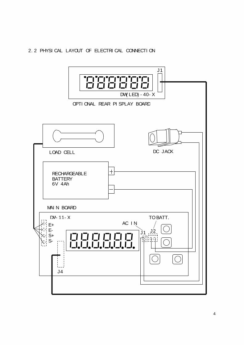
2.2 PHYSICAL LAYOUT OF ELECTRICAL CONNECTION
DW(LED)-40-X
OPTIONAL REAR PISPLAY BOARD
J1
LOAD CELL
RECHARGEABLEBATTERY6V 4Ah
DC JACK
MAIN BOARD
DW-11-X
J2J1
AC INTO BATT.
E+E-S+S-
J4

5
2.3 GENERAL SPECIFICATION
2.3.1 Overall View

6
2.3.2 Overall Dimension:
270(W) X 278(D) X 145(H) mm
2.3.3 Platter Size:
215 X 250 mm
2.3.4 Model Specifications
Model Number DW-3000E DW-6000E DW-15KE DW-30KECapacity 3000g 6000g 15kg 30kgExternal Resolution 1g 2g 0.005kg 0.01kgTare Range Full Tare RangePlatter 215 x 250 mmDisplay Type LED DisplayPower Source By Built-in rechargeable battery or power
adaptorOperationEnvironment
0o~40oC (32o~104oF),Non-condensed. R.H.≦95%
Standard Package Individually PackedDimension: 370(W) x 365(L) x 250(H) mmNet/Gross Weight: 3.7/5.0 kg
2.3.5 Main Components UsedMicroprocessors: 89C52Crystal Oscillator: 11.0592MHzDisplay Device: Common Anode type 7-Segment LED DisplayLoad Cell Used: NMB C2X1 type load cellLoad Cell Capacity: DW-3000E= 6kg
DW-6000E= 10kgDW-15KE= 20kgDW-30KE= 35kg
2.3.6 Analog SpecificationInput sensitivity: 2mV/VZero Drift: 0.3% R.O./10 oC
Zero Balance Range: ±5% of rate capacityLoad Cell Excitation Voltage: DV5VA/D Conversion Speed: 10 times/secondInternal Resolution: 30000

7
3. INITIAL SETUP
3.1 INTERNAL FUNCTIONS AND SETTING METHODS
INTERNAL FUNCTION TABLEFunction Symbol Description
1 F.1 Span value reading and dealer calibration2 F.2 Full display segment and max. capacity check3 F.3 Check offset value and scale configuration4 F.4 Auto power off setting
HOW TO ENTER THE REQUIRED FUNCTION MODEa. Turn scale off.b. Press and hold TARE, then turn scale on. Scale display F.1c. Press TARE until the required function number appears.d. Press MODEe. Press MODE until the required setting appears.f. Press TARE to confirm.g. Repeat step c to f for other function setting, orh. Press ON/ZERO to save settings and return to normal operation.
F.1Span Value Reading and Dealer Calibrationa. Simply enter F.1 to read the A/D counts.b. Press ON/ZERO to clear the A/D counts, apply test mass onto platter,
the span value of test mass will be displayed.c. Refer to Dealer Calibration procedures for dealer calibration.
F.2Display Segment and Rated Capacity & Division CheckWhen function is entered, all segments will be displayed.Check and make sure that no segments are missed.
F.3Total Internal Count Checking and Scale Configurationa. Enter F.3, scale displays the Offset Value when unloaded.b. Apply extra load onto platter, the total internal count value will
be displayed.
SELECT WEIGHT UNITSa. Press and hold MODE until the scale configuration appears.b. To employ all (metric and pound/oz) weight units, press MODE until
‘HI’, ‘OK’, ‘LO’ indicators appear. To disable pound/oz weightunits, press MODE until ‘HI’ indicator appears only.
c. Press ON/ZERO to save setting and back to normal operation status.

8
SELECT SCALE INTERVALa. Press and hold MODE until the scale configuration appears.b. Press MODE until the required scale interval appears.c. Press ON/ZERO to save setting and back to normal operation status.
F.4Auto Power Off SettingTwo modes are available: (Default=4_OFF)0._OFF = Auto Power Off function is disabled.4._OFF = Scale will automatically be turned off after 4 minutes
unused.
3.2 AUTO AND DEALER CALIBRATION PROCEDURES
ACCEPTABLE LOAD FOR AUTO AND DEALER CALIBRATIONModel Number External
DivisionAcceptable Auto and Dealer
Calibration LoadDW-3000E 1/3000 *2kg 1kgDW-6000E 1/3000 *5kg 2kgDW-15KE 1/3000 *10kg 5kgDW-30KE 1/3000 *20kg 10kg* Recommended calibration load
Dealer Calibration Procedures:1. Turn scale off.2. Press and hold TARE, then turn scale on.3. Scale displays F.14. Press MODE5. Scale displays offset value6. Press ON/ZERO7. Press TARE8. Press ON/ZERO9. Press TARE10.Press ON/ZERO, the OK indicator will be lighted up. It means the
scale is ready for dealer calibration. Make sure that the figurebeing displayed is =0 or 1, If not, press ZERO again.
11.Load calibration either load as listed on above table.12.When value displayed is stable, press MODE.13.Wait until the scale starts countdown.14.Calibration completed and scale is ready for operation.
Auto Calibration Procedures:1. Turn scale off2. Press and hold MODE, then turn scale on.3. Scale displays CAL?4. Press MODE

9
5. Scale displays LOAD XXXX or XXXX
6. Load calibration load according to above table.7. Wait until the scale display DONE and starts count down.8. Calibration completed and scale is ready for operation.
3.3 DISABLE CALIBRATION AND AVOIRDUPOIS WEIGHT UNITS WITH MINI JUMPER.(JP2)
The mini jumper(JP2) is used to control calibration and avoirdupoisweight units. Insert a mini jumper between ON position to disablecalibration.
3.4 OFFSET AND SPAN VALUE DATA
OFFSET AND SPAN VALUE DATA TABLEModelNumber
OffsetValue
(Thousand)
Span Value(Thousand) atVarious Load Applied
OffsetControl
SpanControl(Ohm)
R1ADW-3000E 10~14 10~15 at 1kg 20~30 at 2kg VR1 Trimmer 35KDW-6000E 10~14 10~15 at 2kg 20~30 at 4kg VR1 Trimmer 23.2KDW-15KE 10~14 10-15 at 5kg 20-30 at 10kg VR1 Trimmer 25KDW-30KE 10-14 10~15 at 10kg 20~30 at 20kg VR1 Trimmer 15K
READING OFFSET VALUE1 Turn scale off2 Remove all load from platter3 Enter F.3 and read the offset value
READING SPAN VALUE1 Turn scale off2 Remove all load from platter3 Enter F.14 Press ZERO5 Apply load to platter. Span value according to load applied will
be displayed.
HOW TO ADJUST OFFSET VALUEIn case the offset value is out of range, adjust the trimmer locatedat VR1 on the main board to obtain correct offset value.
HOW TO ADJUST SPAN VALUEThe span value is controlledby resistor located on R1, standard resistorvalue of R1 is listed on the above table. If the required span valueis not attained, then change R1 resistor according to either case below:
Span value too low: Increase the resistance of R1.Span value too high: Decrease the resistance of R1.

10
3.5 FLOW CHART
3.5.1 Auto Calibration (for end-user)
NO
YES
YES
NO
NO
YES
PRESS "MODE"& "ON/ZERO"
DISPLAYFULL SCENE
RELEASE"ON/ZERO" KEY
DISPLAY"CAL.?"
RELEASE"MODE" KEY
PRESS "MODE"OR "ZERO" KEY
CALIBRA-TING?
DISPLAY"no"
DISPLAY"99999"
DISPLAY"00000"
STANDBY FOROPERATION
DISPLAY"DONE"
CORRECT WEIGHTASSIGNED?
PUT A ASSIGNEDWEGHT ON PLATTER
DISPLAY"YES"
START
LCDPANORAMA
DISPLAY" 0"
DISPLAY"LOAD"
DISPLAY"XXXX"
DISPLAY"or"
DISPLAY"XXXX"
DISPLAY"99999"
DISPLAY"00000"
WEIGHT STILLON THE PLATTER?
DISPLAY"XXXX"
"XXXX"=ASSIG-NED WEIGHT
CALIBRATING?
"MODE"=YES"ZERO" =NO

11
3.5.2 Function Test (for technicians only)
COUNT DOWN
" MODE " Other
"TARE"
F1
PRESSKEY? S
lF2
F2
F1
PRESS "TARE"& "ON/ZERO"
LCD PANOR-AMIC VIEW
RELEASE"ON/ZERO"
KEY
RELEASE"TARE" KEY
START
S
99999
11111
00000
o
0
STANDBY FOROPERATION

12
NO
NO
NOTE :
1: TARE key2: ZERO key
YES
NO
YES
NO
NO
YES
l
DISPLAY"XXXX".
PRESS "ZERO " ?
CAL.LOOP
0
PRESSKEY CODE:1 , 2 , 1 , 2
LEGITIMATEPROCEDURE
0 OK
PUT ON THEASSIGNEDWEIGHT
JP2 (CAL.)IS ON?
j
xxxx:Show offset
YES
A/D _ > 0 + / - 3counts
Key inPrivateCode
C
k
TESTKEYBOARD
k
SWITCH OFF ?
NO END
YES
k : key code
" OK " AcceptPrivate Code
k
YESPRESS"MODE" ?
WEIGHTASSIGNED
C
DONE
S
DISPLAYSPAN VALUE
j

13
Other "TARE"
"MODE"
"MODE"other
"TARE"
other "TARE"
"MODE"
other "TARE"
F2
s
F1
S F3
S F4
PRESS KEY?
PRESSKEY?
PRESSKEY?
F2
L.C.DPANORAMICVIEW
F3
XXXX:CapacityXXXX
WEIGHT UNIT CHANGED:
kg<--->kg/lb
SCALE INTERVAL CHANGED:
i.e. 3000x1g<--->3000x0.5g
PRESSKEY? F1S

14
other
other "TARE"
F4
F4
PRESSKEY?
4_oFF
PRESSKEY?
" MODE "
0_oFF
S
" MODE
F1
Auto shut-offwhen not inuse for 4 min.
F1
" TARE "
NoAuto shut-off

15
CHECK LOAD CELL,A/D UNIT,OFFSETVALUE
CHECK POWERSUPPLY,A/D UNIT,BAD SOLDERING,TEMP. EFFECT
CHECK PLATTERSTOPPER,LOADCELL,A/D UNIT,BAD SOLDERING
RE-CALIBRATETHE SCALE
CHECK PLATTERSTOPPER,LOADCELL,OFFSETVALUE
4. TROUBLE SHOOTING
4.1 TROUBLE SHOOTING LOOP
POWER ON
COUNT DOWN?
NO DISPLAY DISPLAY RANDOMFIGURE
CHECK POWER SUPPLY,CPU,TACT SW.
CHECK CPU,7-SEGMENT-LEDS,OK
COUNTS ANDTHEN ZERO?
OK
PROPER READOUT?
CORRECT READOUT?
NORMAL OPERATION
SHOW “00000”
UNSTABLEZERO DRIFT
OK
OK
INCORRECTCAN’T REACH THEFULL CAPACITY

16
4.2 PARTS AND COMPONENTS TROUBLE SHOOTING
4.2.1 Power Supply Checking
4.2.1.1 Relevant parts:Main Board (DW-11-X)Q5 (C1061)ZD1 (8.2V)BR1 (W04/1A)Q1 (A1515)Q2 (C945)Q3 (C945)R41 (1.2 ohm, 1/2W)Q6 (A733)U5(2950-5)U6(2930-5)6V 4Ah BATTERY
Description:1) AC Adaptor: This AC Adaptor provides power of DC9~12V,500mA
2) Battery: Built-in Rechargeable Battery 6V/4Ah
3) How Battery is charged completely?The charging voltage is regulated by Q5 (C1061) and ZD1 (8.2V) forabout 7 volts.Thechargingcurrentwillgodownautomaticallywhenvoltagereached.Q3 (C945) and R41 (1.2R, 1/2W) provide Over-Current protection.

17
4) +5V power drives analog circuit system.U5 (2950-5) is a 5volts Voltage Regulator.
5) +5V power drives digital circuit system.U6 (2930-5) is a 5volts Voltage Regulator.
6) Auto-off:If the scale is set on 4_oFF or even under LO-BAT situation, aftersome minutes the CPU will release a low potential signal to drawdown Q2, then Q1 cuts off, the scale will be shut down immediately.
7) Low Power Detection:The Q6 (A733) is designed to detect the power level. When batterypower is less than 5.5V, the collector pole of Q6 will become lowpotential level, mean while CPU detects the level changed thenCPU will light up LO-BAT indicator on the display.
4.2.1.2 Input voltage: 5.5V or higherCheck and recharge battery if voltage less than 5.5V.Check DC-JACK or AC Adaptor if been defective.
4.2.1.3 System voltage (Vcc): 5V +/- 10%Check that the system voltage is within 5V +/- 10%a) less than 4.5V, the CPU may not work properly.b) more than 6V, it may damage some components .
4.2.2 Platter Stopper CheckingThe platter device shall not touch anything around itself duringoperation. Check that the platter is not contacted with the upper(no load) and/or lower (with load) stopper.
4.2.3 LED Display Checking
4.2.3.1 Check that every LED module is soldered properly onto the mainboard.
4.2.3.2 Check whether segment of LED module is ruined.
4.2.4 CPU Checking
4.2.4.1 Check that all pins are seated properly into the socket.
4.2.4.2 Check that the Crystal Oscillator works.
4.2.4.3 Check the RESET is normally low.
18
4.2.5 A/D Unit Checking
4.2.5.1 Check that the +5VA & +5V powers are correctly fed to theA/D unit.
4.2.5.2 Check that the signal output of loadcell is normal.
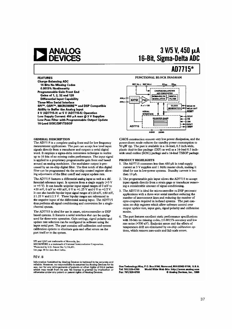
4.2.5.3 Check OP. Amplifiers & A/D Converter (AD7715).
When no error is found with the above checking procedures, the troublecan be caused on the loadcell or the PCB itself. Replace a new onecould be better to identify the defective.
In this way, the readout of weight would be varied because of the outputvoltage of loadcell and different span value, so re-calibration isrequired after this replacement.

19
5. ELECTRICAL CIRCUITRY
5.1 SCHEMATICS

20

21

22

23

24

25
5.2 PCB LAYOUT
DW-11-2 TOP LAYER
DW-11-2 BOTTOM LAYER

26
DW-11-2 TOP OVERLAY
DW-11-2 BOTTOM OVERLAY

27
DW-40-1 TOP LAYER
DW-40-1 BOTTOM LAYER
28
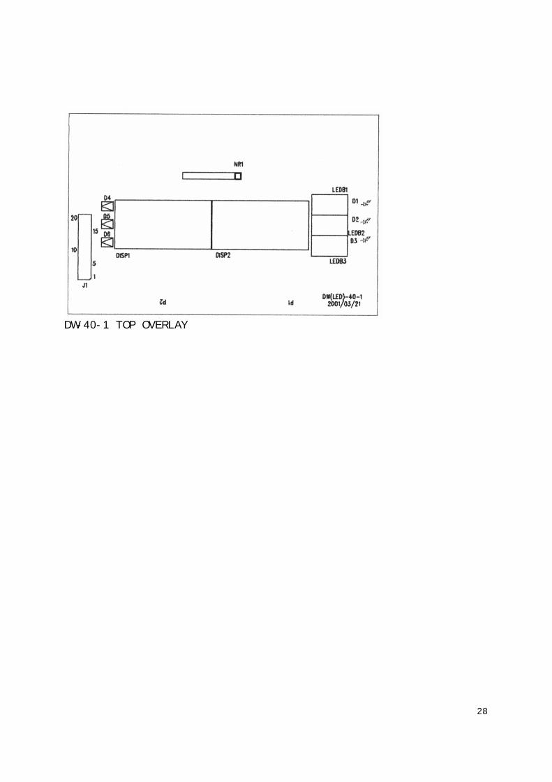
DW-40-1 TOP OVERLAY
29
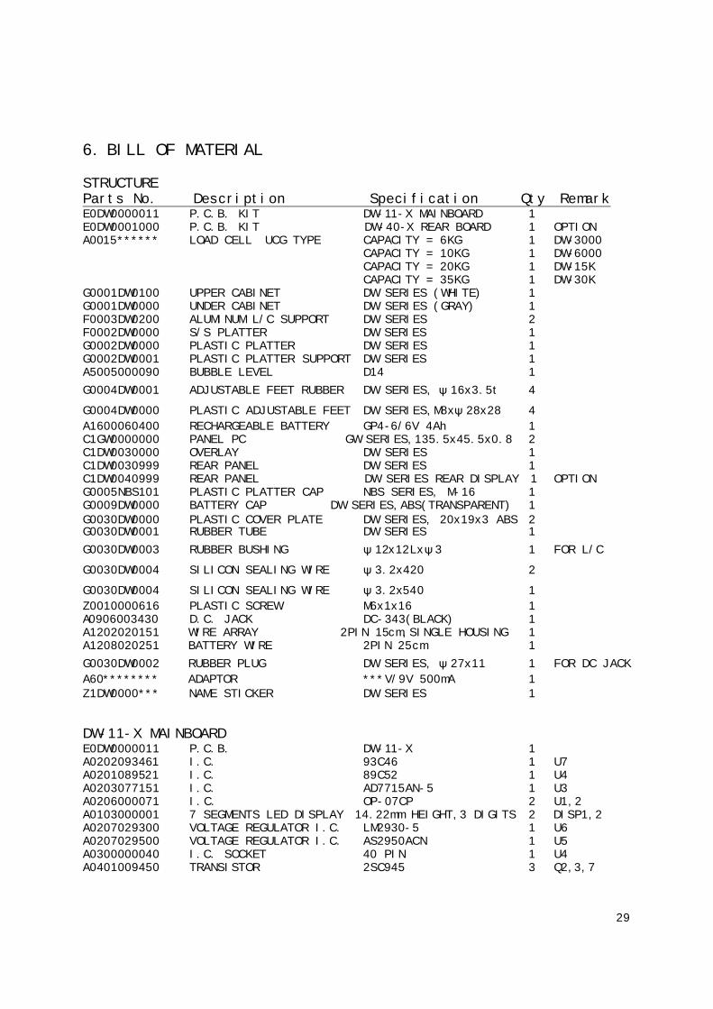
6. BILL OF MATERIAL
STRUCTUREParts No. Description Specification Qty RemarkE0DW0000011 P.C.B. KIT DW-11-X MAINBOARD 1E0DW0001000 P.C.B. KIT DW-40-X REAR BOARD 1 OPTIONA0015****** LOAD CELL UCG TYPE CAPACITY = 6KG 1 DW-3000
CAPACITY = 10KG 1 DW-6000CAPACITY = 20KG 1 DW-15KCAPACITY = 35KG 1 DW-30K
G0001DW0100 UPPER CABINET DW SERIES (WHITE) 1G0001DW0000 UNDER CABINET DW SERIES (GRAY) 1F0003DW0200 ALUMINUM L/C SUPPORT DW SERIES 2F0002DW0000 S/S PLATTER DW SERIES 1G0002DW0000 PLASTIC PLATTER DW SERIES 1G0002DW0001 PLASTIC PLATTER SUPPORT DW SERIES 1A5005000090 BUBBLE LEVEL D14 1G0004DW0001 ADJUSTABLE FEET RUBBER DW SERIES, ψ16x3.5t 4
G0004DW0000 PLASTIC ADJUSTABLE FEET DW SERIES,M8xψ28x28 4A1600060400 RECHARGEABLE BATTERY GP4-6/6V 4Ah 1C1GW0000000 PANEL PC GW SERIES,135.5x45.5x0.8 2C1DW0030000 OVERLAY DW SERIES 1C1DW0030999 REAR PANEL DW SERIES 1C1DW0040999 REAR PANEL DW SERIES REAR DISPLAY 1 OPTIONG0005NBS101 PLASTIC PLATTER CAP NBS SERIES, M-16 1G0009DW0000 BATTERY CAP DW SERIES,ABS(TRANSPARENT) 1G0030DW0000 PLASTIC COVER PLATE DW SERIES, 20x19x3 ABS 2G0030DW0001 RUBBER TUBE DW SERIES 1G0030DW0003 RUBBER BUSHING ψ12x12Lxψ3 1 FOR L/C
G0030DW0004 SILICON SEALING WIRE ψ3.2x420 2
G0030DW0004 SILICON SEALING WIRE ψ3.2x540 1Z0010000616 PLASTIC SCREW M6x1x16 1A0906003430 D.C. JACK DC-343(BLACK) 1A1202020151 WIRE ARRAY 2PIN 15cm,SINGLE HOUSING 1A1208020251 BATTERY WIRE 2PIN 25cm 1G0030DW0002 RUBBER PLUG DW SERIES, ψ27x11 1 FOR DC JACKA60******** ADAPTOR ***V/9V 500mA 1Z1DW0000*** NAME STICKER DW SERIES 1
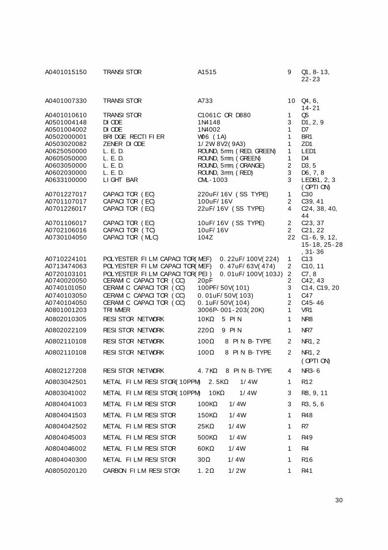
DW-11-X MAINBOARDE0DW0000011 P.C.B. DW-11-X 1A0202093461 I.C. 93C46 1 U7A0201089521 I.C. 89C52 1 U4A0203077151 I.C. AD7715AN-5 1 U3A0206000071 I.C. OP-07CP 2 U1,2A0103000001 7 SEGMENTS LED DISPLAY 14.22mm HEIGHT,3 DIGITS 2 DISP1,2A0207029300 VOLTAGE REGULATOR I.C. LM2930-5 1 U6A0207029500 VOLTAGE REGULATOR I.C. AS2950ACN 1 U5A0300000040 I.C. SOCKET 40 PIN 1 U4A0401009450 TRANSISTOR 2SC945 3 Q2,3,7
30
A0401015150 TRANSISTOR A1515 9 Q1,8-13,22-23
A0401007330 TRANSISTOR A733 10 Q4,6,14-21
A0401010610 TRANSISTOR C1061C OR D880 1 Q5A0501004148 DIODE 1N4148 3 D1,2,9A0501004002 DIODE 1N4002 1 D7A0502000001 BRIDGE RECTIFIER W06 (1A) 1 BR1A0503020082 ZENER DIODE 1/2W 8V2(9A3) 1 ZD1A0625050000 L.E.D. ROUND,5mm,(RED,GREEN) 1 LED1A0605050000 L.E.D. ROUND,5mm,(GREEN) 1 D4A0603050000 L.E.D. ROUND,5mm,(ORANGE) 2 D3,5A0602030000 L.E.D. ROUND,3mm,(RED) 3 D6,7,8A0633100000 LIGHT BAR CML-1003 3 LEDB1,2,3
(OPTION)A0701227017 CAPACITOR (EC) 220uF/16V (SS TYPE) 1 C30A0701107017 CAPACITOR (EC) 100uF/16V 2 C39,41A0701226017 CAPACITOR (EC) 22uF/16V (SS TYPE) 4 C24,38,40,
44A0701106017 CAPACITOR (EC) 10uF/16V (SS TYPE) 2 C23,37A0702106016 CAPACITOR (TC) 10uF/16V 2 C21,22A0730104050 CAPACITOR (MLC) 104Z 22 C1-6,9,12,
15-18,25-28,31-36
A0710224101 POLYESTER FILM CAPACITOR(MEF) 0.22uF/100V(224) 1 C13A0713474063 POLYESTER FILM CAPACITOR(MEF) 0.47uF/63V(474) 2 C10,11A0720103101 POLYESTER FILM CAPACITOR(PEI) 0.01uF/100V(103J) 2 C7,8A0740020050 CERAMIC CAPACITOR (CC) 20pF 2 C42,43A0740101050 CERAMIC CAPACITOR (CC) 100PF/50V(101) 3 C14,C19,20A0740103050 CERAMIC CAPACITOR (CC) 0.01uF/50V(103) 1 C47A0740104050 CERAMIC CAPACITOR (CC) 0.1uF/50V(104) 2 C45-46A0801001203 TRIMMER 3006P-001-203(20K) 1 VR1A0802010305 RESISTOR NETWORK 10KΩ 5 PIN 1 NR8
A0802022109 RESISTOR NETWORK 220Ω 9 PIN 1 NR7
A0802110108 RESISTOR NETWORK 100Ω 8 PIN B-TYPE 2 NR1,2
A0802110108 RESISTOR NETWORK 100Ω 8 PIN B-TYPE 2 NR1,2(OPTION)
A0802127208 RESISTOR NETWORK 4.7KΩ 8 PIN B-TYPE 4 NR3-6
A0803042501 METAL FILM RESISTOR(10PPM) 2.5KΩ 1/4W 1 R12
A0803041002 METAL FILM RESISTOR(10PPM) 10KΩ 1/4W 3 R8,9,11
A0804041003 METAL FILM RESISTOR 100KΩ 1/4W 3 R3,5,6
A0804041503 METAL FILM RESISTOR 150KΩ 1/4W 1 R48
A0804042502 METAL FILM RESISTOR 25KΩ 1/4W 1 R7
A0804045003 METAL FILM RESISTOR 500KΩ 1/4W 1 R49
A0804046002 METAL FILM RESISTOR 60KΩ 1/4W 1 R4
A0804040300 METAL FILM RESISTOR 30Ω 1/4W 1 R16
A0805020120 CARBON FILM RESISTOR 1.2Ω 1/2W 1 R41

31
A0805021101 CARBON FILM RESISTOR 100Ω 1/2W 1 R38
A0805041101 CARBON FILM RESISTOR 100Ω 1/4W 1 R10
A0805041102 CARBON FILM RESISTOR 1KΩ 1/4W 2 R15,45
A0805041103 CARBON FILM RESISTOR 10KΩ 1/4W 4 R13,14,43,52
A0805041153 CARBON FILM RESISTOR 15KΩ 1/4W 1 R42
A0805041221 CARBON FILM RESISTOR 220Ω 1/4W 1 R39
A0805041223 CARBON FILM RESISTOR 22KΩ 1/4W 2 R47,50
A0805041272 CARBON FILM RESISTOR 2.7KΩ 1/4W 2 R44,51
A0805041471 CARBON FILM RESISTOR 470Ω 1/4W 1 R40
A0805041472 CARBON FILM RESISTOR 4.7KΩ 1/4W 2 R22,53
A0805041473 CARBON FILM RESISTOR 47KΩ 1/4W 1 R46A0901010020 CONNECTOR 2PIN WAFER 1 J1A0901010040 CONNECTOR 4PIN WAFER 1 J3(RS-232)A0902010020 CONNECTOR 2PIN,PITCH=3.9mm 1 J2A0907010030 CONNECTOR(PIN PLUG) 1 * 3 PIN 180° 1 JP2A0907020200 CONNECTOR(PIN PLUG) 2 * 10 PIN 1 J4(OPTION)A0910110020 CONNECTOR 2 PIN ,MINIJUMP 1 JP2A1005030512 FERRITE BEAD 3.5*6*0.8 2 L1,2A1100311059 CRYSTAL 11.0592MHZ 1 X1A1306000003 TACT SW KPT-1104B 4 SW1-4A1500000004 BUZZER OBO-15210 1 BZ1A1007000001 FERRITE CORE TR-16x9x28 1 FOR L/CA1005030610 FERRITE BEADS ψ6x10,2.5T 1 L3A1007000008 FERRITE CORE TR-14.2x7.2x15mm(L8) 1 DC INPUT
OM-41-X REAR BOARDE0DW0001000 P.C.B DW-40-X 1A0103000001 7 SEGMENTS LED DISPLAY 14.22mm HEIGHT,3 DIGITS 2 DISP1,2A0605050000 L.E.D. ROUND,5mm,(GREEN) 1 D4A0603050000 L.E.D. ROUND,5mm,(ORANGE) 2 D3,5A0602030000 L.E.D. ROUND,3mm,(RED) 3 D6,7,8A0633100000 LIGHT BAR CML-1003 3 LEDB1,2,3
(OPTION)A0802022109 RESISTOR NETWORK 220Ω 9 PIN 1 NR7
A0907021200 CONNECTOR(PIN PLUG) 2 * 10 PIN 90° 1 J4A1203200400 FLAT CABLE 20PIN,40cm 1============================================================================

32
7. APPENDIXPARTS EXPLOSION:

33
TEM PART NAME DESCRIPTION QTY
1 UPPER CABINET DW SERIES (WHITE) 1

34
2 PLASTIC COVER PLATE DW SERIES, 20x19x3 ABS 23 ALUMINUM L/C SUPPORT DW SERIES 24 S/S SCREW(NYLOK) M4 x 0.7 x 20 45 LOAD CELL UCG TYPE OR EQUIVALENT 16 S/S HEX. SCREW M6 x 1 x 20 47 RUBBER TUBE DW SERIES 1
8 RUBBER BUSHING DW SERIES,ψ12x12Lxψ3 1
9 S/S SCREW M4 x 0.7 x 10 810 PLASTIC PLATTER SUPPORT DW SERIES 111 PLASTIC PLATTER DW SERIES 112 PLASTIC SCREW M6 x 1 x16,M06016D,PA66 113 PLASTIC PLATTER CAP NBS SERIES, M-16 114 S/S PLATTER DW SERIES,251 x 216 x 0.8t 115 FLAT CABLE 20PIN,40cm 116 BATTERY WIRE 2PIN,25cm 117 RECHARGEABLE BATTERY GP4-6/6V 4Ah 1
18 SILICON SEALING WIRE ψ3.2x420 1
19 BATTERY CAP DW SERIES,ABS(TRANSPARENT) 120 S/S HEX. SCREW M5 x 0.8 x 12 221 P.C.B. DW-11-X 122 SCREW M3 x 10,TAPER 4/223 PANEL PC GW SERIES,135.5x45.5x0.8 224 OVERLAY DW SERIES 125 P.C.B.(REAR DISPLAY) DW-40-X 126 REAR PANEL DW SERIES 127 BUBBLE LEVEL D14 128 NAME STICKER DW SERIES 129 UNDER CABINET DW SERIES 1
30 SILICON SEALING WIRE ψ3.2x420 1
31 SILICON SEALING WIRE ψ3.2x540 1
32 D.C. JACK DC-343(BLACK) 133 SCREW M2 x 6,TAPER 234 PLASTIC ADJUSTABLE FEET DW SERIES,M8xψ28x28 4
35 ADJUSTABLE FEET RUBBER DW SERIES, ψ16x3.5t 4
36 RUBBER PLUG DW SERIES, ψ27x11 1
37 S/S SCREW M3 x 12,TAPER 6

35

36
37

38

39
7 SEGMENT LED DISPLAY(14.22mm HEIGHT,3 DIGITS)