dynamic on-line motor analysis test
TRANSCRIPT
DYNAMIC ON-LINE MOTOR ANALYSIS TEST
Case study on HV Induction motor, 6000 V, 8MW
www.koncar-institut.com

Dyn
amic
On
-lin
e M
oto
r A
nal
ysis
TEST RESULTSTEST ITEM
02
The latest generation of dynamic on-line motor analysis test doesn’t require for a motor to be stopped. The testing provides comprehensive information on general condition, operation, load, power supply and drive of the motor.
HV Induction motor
Power [kW] 8000
Current [A] 880
Frequency [Hz] 50
Voltage [V] 6000
cos φ 0,91
Efficiency η [%] 96
Speed [r/min] 994
Synchronous speed [r/min] 1000
Slip [%] 0,6
Rotor bars 112
Stator slots 126
TEST VALUE STATUS CAUTION LEVEL WARN. LEVEL
Voltage Level (Over) [%] 98,72 Good 110,00 120,00
Voltage Level (Under) [%] 98,72 Good 95,00 90,00
Voltage Unbalance [%] 0,19 Good 2,00 3,50
THD [% of fund.] 0,24 Good 7,00 9,00
Total Distortion [% of fund.] 0,28 Good 10,00 12,00
Current Level [%] 61,31 Good 110,00 120,00
Current Unbalance [%] 0,14 Good 10,00 20,00
Load [%] 59,79 Good 110,00 125,00
Ef. Service Factor [p.u.] 0,60 Good 1,10 1,25
Rotor Bar [db] -67,68 Good -45,00 -36,00
Op. Point [%] 0,00 Good 20,00 30,00
Loss Difference [%] 0,00 Good 25,00 50,00

Dyn
amic
On
-lin
e M
oto
r A
nal
ysis
Voltage Level TestPOWER QUALITY DOMAIN
03
» Voltage Level Test
All voltages are around 99% of the nominal value.
There is no over/under voltage measured.
Voltage Level
The test detects presence of overvoltage or undervoltagewith regard to rated voltage. The presence of overvoltage stresses the motor insulation, undervoltage can cause current increase above the nominal values.

Dyn
amic
On
-lin
e M
oto
r A
nal
ysis
Voltage Level TestPOWER QUALITY DOMAIN
04
Voltage Unbalance
Unbalanced voltage condition causes negative sequence currents within the stator, resulting in excessive heat. NEMA derating curve specifies maximum load for each unbalance.
» Voltage Unbalance Test
Voltage unbalance is under 0,5%. If value above 3.5% is reached, the asymmetry can cause negative sequence currents. This will increase machine losses and additionally heat the machine winding.

Voltage Level Test
Dyn
amic
On
-lin
e M
oto
r A
nal
ysis
POWER QUALITY DOMAIN
05
Total Harmonics Distortion and Total Distortion
Total Harmonic Distortion (THD) and Total Distortion (TD) deal with quantifying the effect of nonfundamental components to the voltage and current waveform. TD values must result in higher values than THD.
Both, THD and TD values are low and do not indicate possible machine performance problems.
Voltage Level Test
Dyn
amic
On
-lin
e M
oto
r A
nal
ysis
06
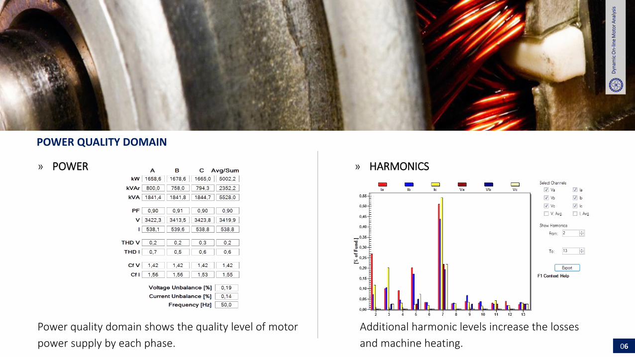
» POWER
POWER QUALITY DOMAIN
» HARMONICS
Power quality domain shows the quality level of motor
power supply by each phase.
Additional harmonic levels increase the losses
and machine heating.

Dyn
amic
On
-lin
e M
oto
r A
nal
ysis
Voltage Level TestMACHINE PERFORMANCE DOMAIN
07
Effective Service Factor
Effective service factor graphically displays the estimated percentage of load derated within the NEMA derating factor. This test identifies how closely the motor is operating to its effective service factor. The test predicts heat-based deterioration.
» Effective Service Factor
Motor is operating “in green” area, with NEMA derating factor 1.

Dyn
amic
On
-lin
e M
oto
r A
nal
ysis
Voltage Level TestMACHINE PERFORMANCE DOMAIN
08
Load and Losses
Motor efficiency is calculated from operating load and measured losses (mostly heat). High losses can cause increase of the motor temperature.
Motor is operating at high efficiency.
Motor Load Measured Losses
Dyn
amic
On
-lin
e M
oto
r A
nal
ysis
Voltage Level TestCURRENT DOMAIN
09
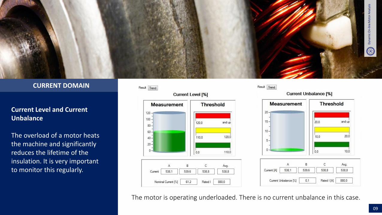
Current Level and Current Unbalance
The overload of a motor heats the machine and significantly reduces the lifetime of the insulation. It is very important to monitor this regularly.
The motor is operating underloaded. There is no current unbalance in this case.

Voltage Level Testd
Dyn
amic
On
-lin
e M
oto
r A
nal
ysis
10
SPECTRUM DOMAIN
Order nLower sideband [Hz] Upper sideband [Hz]
Hz dB Hz dB
1 49,68 -67,68 50,32 -68,5
2 49,35 -64,1 50,65 -64,1
3 49,03 -75,5 50,97 -71,01
» ROTOR BAR
Broken rotor bar sidebands are low (>-60 dB).
The values indicate excellent rotor condition.
The graph shows stator current spectrum with broken rotor bar sidebands marked. In case when there is a rotor bar damage on a certain frequency, new harmonics will appear showing abnormal values.

Voltage Level Testd
Dyn
amic
On
-lin
e M
oto
r A
nal
ysis
11
SPECTRUM DOMAIN
Order nLower sideband [Hz] Upper sideband [Hz]
Hz dB Hz dB
1 33,4 -78,39 66,6 -79,17
2 16,9 -81,29 83,1 -79,86
3 0,3 -83,6 99,7 -78,4
» ECCENTRICITY SIDEBANDS
Eccentricity sidebands are low. There is no
indication of static or dynamic eccentricity.
The graph shows stator current spectrum with eccentricity sidebands marked. Here it is important to watch for frequencies and corresponding harmonics that are present because of the static/dynamic eccentricity.

Voltage Level Testd
Dyn
amic
On
-lin
e M
oto
r A
nal
ysis
12
SPECTRUM DOMAIN
» V/I Spectrum
Stator current spectrum with broken rotor bar
sidebands marked
Stator current spectrum with broken rotor bar sidebands marked.
There are no significant sidebands in current spectrum up
to 500 Hz. Measurement was taken with 1 kHz for 120 sec.

Dyn
amic
On
-lin
e M
oto
r A
nal
ysis
Voltage Level TestTORQUE DOMAIN
13
Torque Ripple Results
Motor torque is slightly rippled. There is no indication of serious motor/load problem. Torque ripple should be trended in future.
Torque Ripple
Dyn
amic
On
-lin
e M
oto
r A
nal
ysis
Voltage Level TestTORQUE DOMAIN
14
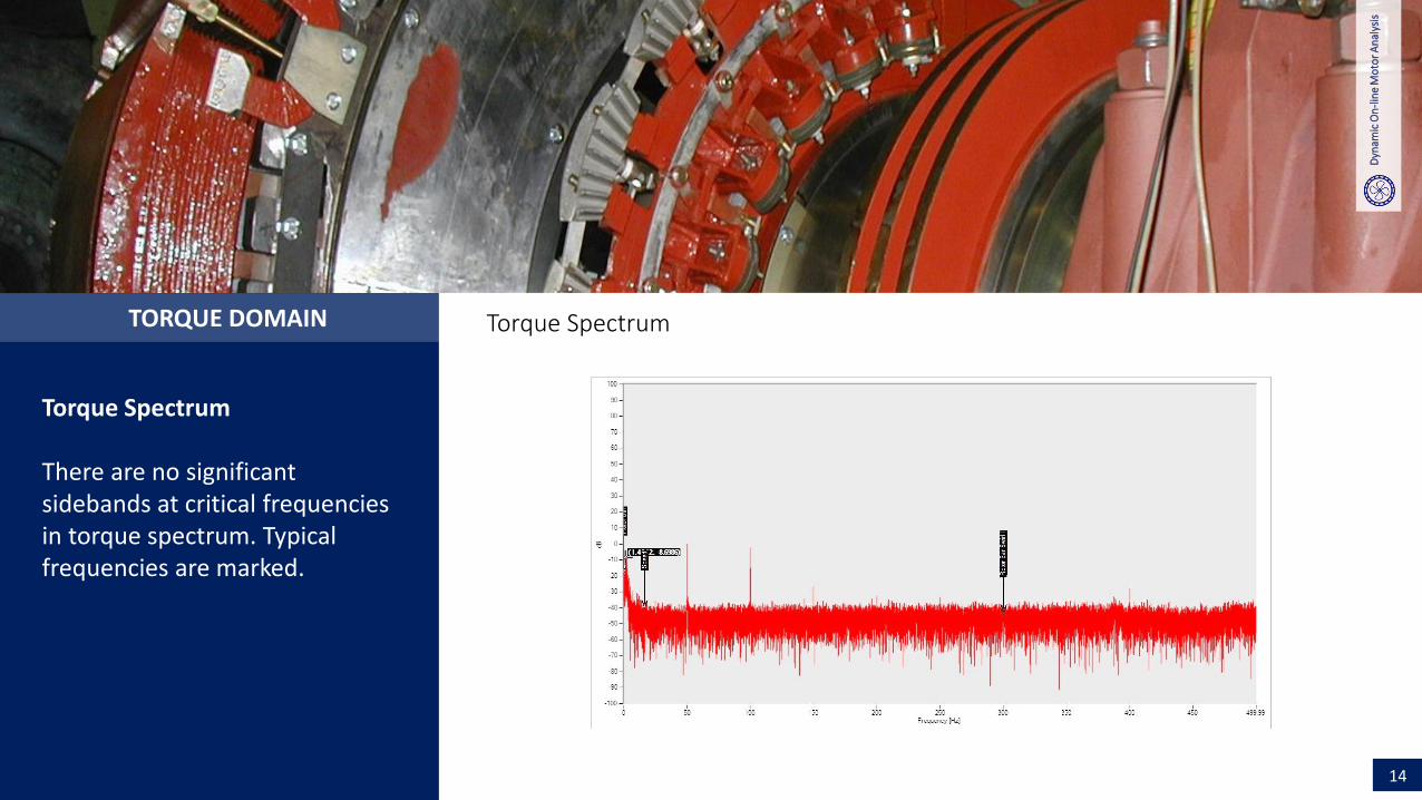
Torque Spectrum
There are no significant sidebands at critical frequencies in torque spectrum. Typical frequencies are marked.
Torque Spectrum

Dyn
amic
On
-lin
e M
oto
r A
nal
ysis
Voltage Level TestCONNECTION DOMAIN
15
Supply voltage is sinusoidal and stator currents are slightly rippled. Situation is normal for induction motor operation.Voltage/current phasors are symmetrical and motor (as well as measurement sensors) is properly connected.
» WAVEFORMS » PHASORS
Voltage – Current waveforms
Dyn
amic
On
-lin
e M
oto
r A
nal
ysis
Voltage Level TestCONCLUSION
16
There is no evidence of any faults. The motor is in good condition. The recommendation is to repeat this test in two years.
» Induction Motor is in good condition. Supply voltage is symmetrical. There is no over/under voltage
» THD and TD values are low. Effective service factor is 1.08 and motor is working with NEMA derating factor 1, with high efficiency
» There are no significant sidebands in stator current spectrum. Sidebands for rotor bar faults are low as well as for eccentricity
» Motor torque is slightly rippled and it is advised to trend it in time.

CONTACT US TO ARRANGE A VISIT TO YOUR FACILITY
Fallerovo šetalište 22, PP 202Zagreb 10002, Croatia
KONČAR Electrical Engineering Institute
@
+3851 3667-315; 3851 3666-351
www.koncar-institut.com
+3851 3667-309
» Hydro plants
» Thermal plants
» Oil refineries
» Cement plants
» Sugar production
» Off-shore platforms
» Paper industry
» Steel factories
REFERENCES
» Fertilizer production
» Glass industry
» Shipyards
» Water management
» Water distribution
» Pharmaceuticals
» Food and beverage
» Nuclear plants