e 01 detail - figure 01 page 70 e 04 e 01 · 750 110 pavement isolation foundation e 04 concrete...
TRANSCRIPT
Detail - Figure 01 PAGE 70
VARIANT-HAUS
All dimensions are given in mm
ANNEX: 24
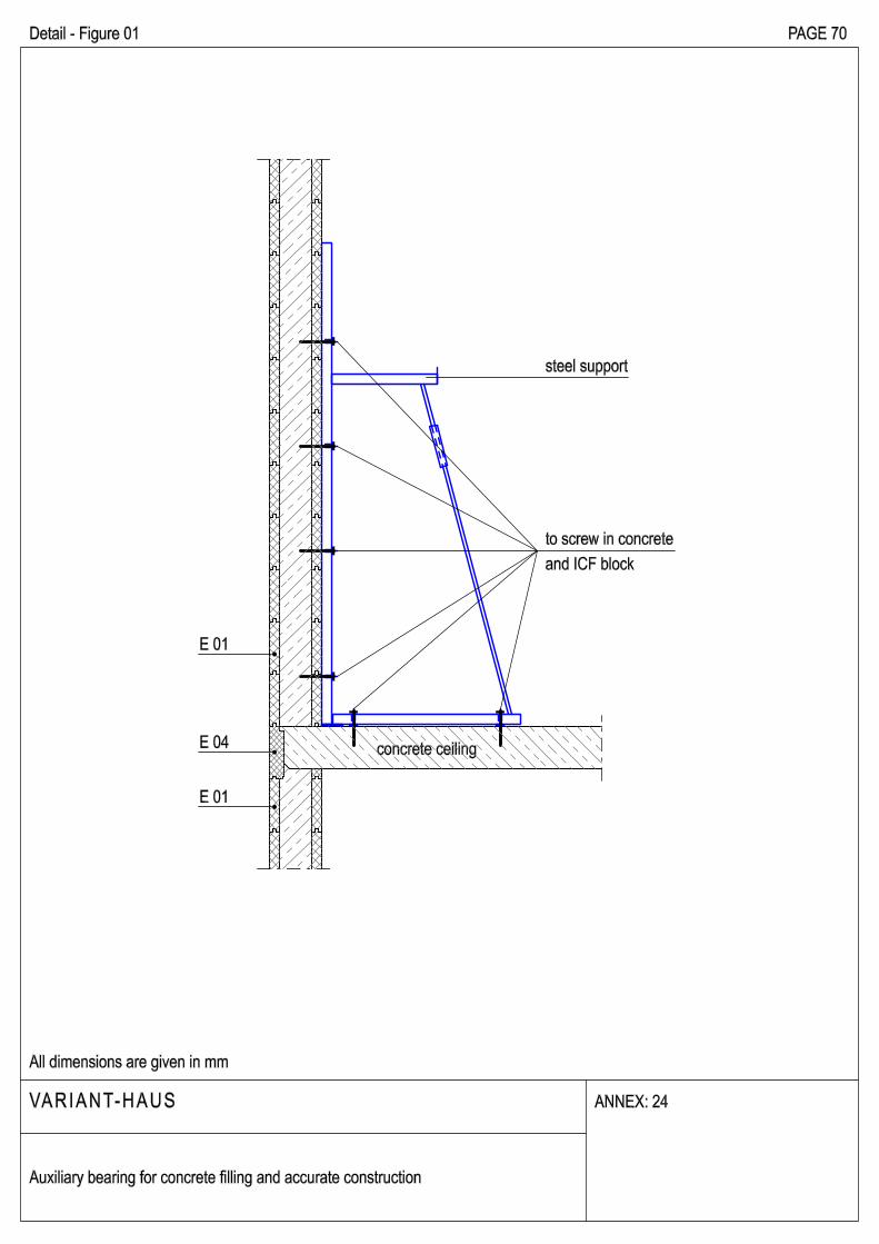
concrete ceiling
Auxiliary bearing for concrete filling and accurate construction
E 01
E 04
E 01
to screw in concrete
and ICF block
steel support
47
05
00
50
06
00
23
02
.5
23
00
10
2.5500
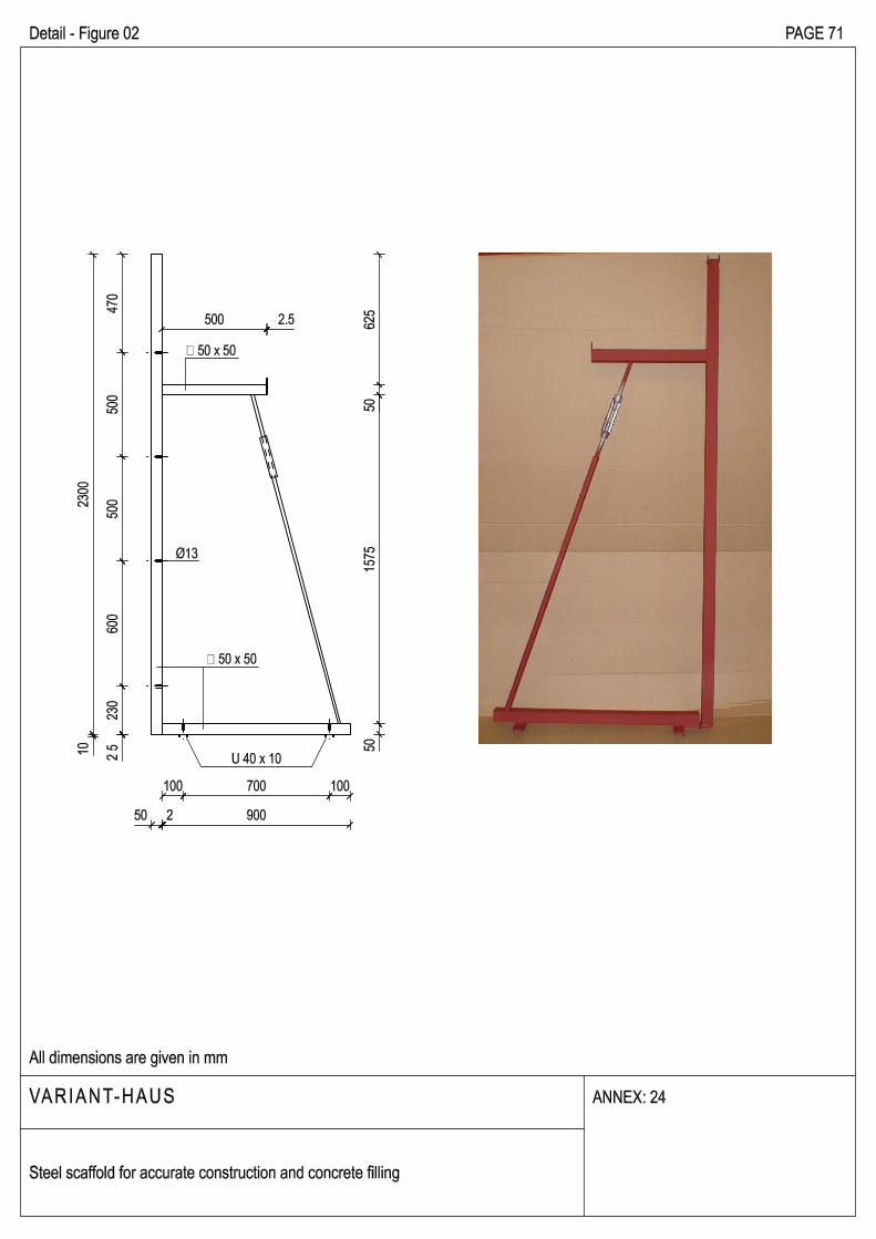
Ø13
50 2 900
100 700 100
62
55
01
57
55
0
U 40 x 10
� 50 x 50
� 50 x 50
Detail - Figure 02 PAGE 71
VARIANT-HAUS
All dimensions are given in mm
ANNEX: 24
Steel scaffold for accurate construction and concrete filling
75
0110
pavement
isolation
foundation
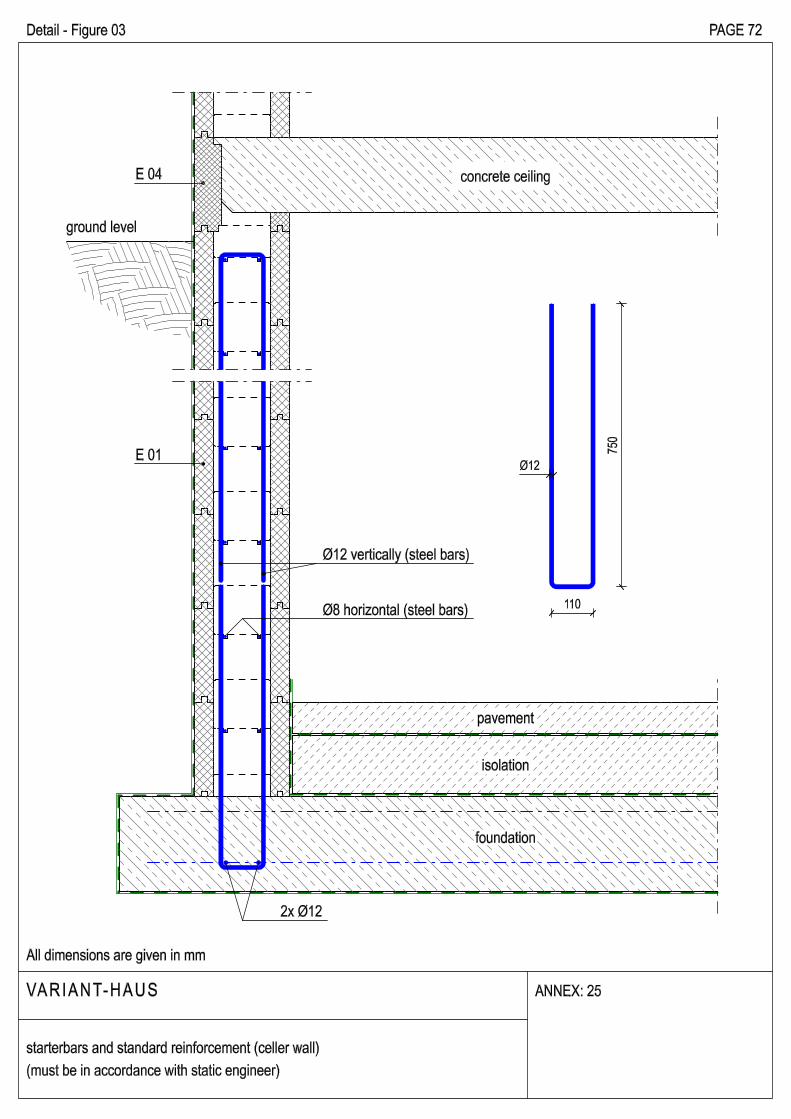
concrete ceilingE 04
E 01
ground level
Ø12
Ø12 vertically (steel bars)
Detail - Figure 03
VARIANT-HAUS
All dimensions are given in mm
ANNEX: 25
starterbars and standard reinforcement (celler wall)
(must be in accordance with static engineer)
PAGE 72
Ø8 horizontal (steel bars)
2x Ø12
E 01
E 01
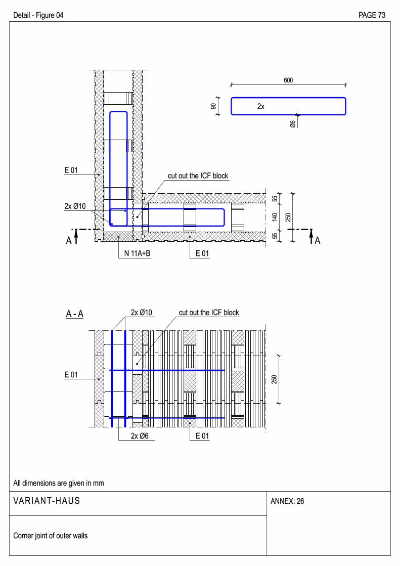
90
600
Ø6
2x
cut out the ICF block
Detail - Figure 04 PAGE 73
VARIANT-HAUS
All dimensions are given in mm
ANNEX: 26
Corner joint of outer walls
AA
55
14
05
5
25
0
25
0
cut out the ICF block
2x Ø6
E 01
E 01
A - A
N 11A+B
2x Ø10
2x Ø10
E 01
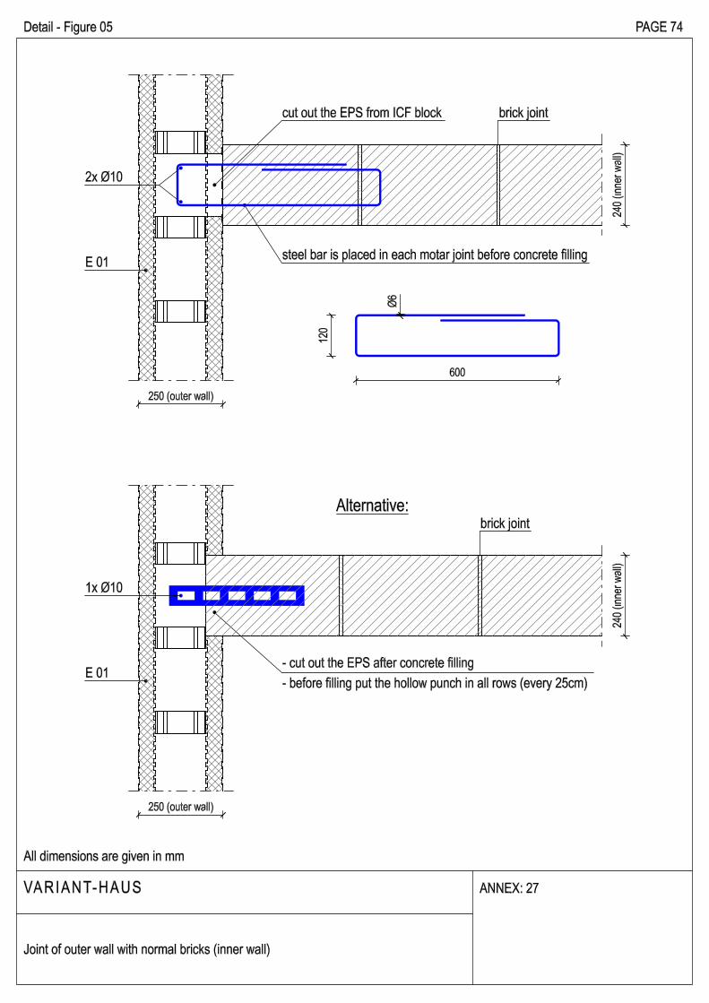
Detail - Figure 05 PAGE 74
VARIANT-HAUS
All dimensions are given in mm
ANNEX: 27
Joint of outer wall with normal bricks (inner wall)
cut out the EPS from ICF block
600
12
0
Ø6
E 01- cut out the EPS after concrete filling
- before filling put the hollow punch in all rows (every 25cm)
Alternative:
steel bar is placed in each motar joint before concrete filling
brick joint
brick joint
250 (outer wall)
250 (outer wall)
24
0 (
inn
er w
all)
24
0 (
inn
er w
all)
2x Ø10
1x Ø10
50
0
Ø 6
2x
500
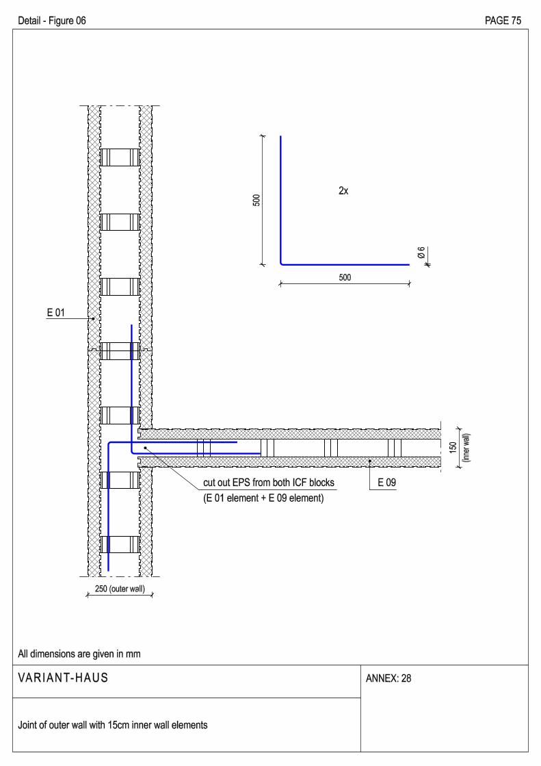
E 09
15
0
cut out EPS from both ICF blocks
(E 01 element + E 09 element)
Detail - Figure 06 PAGE 75
VARIANT-HAUS
All dimensions are given in mm
ANNEX: 28
Joint of outer wall with 15cm inner wall elements
250 (outer wall)
(inn
er w
all)
E 01
E 01
25
0
250 250
A - A
A A
25
0
2x10
0
250
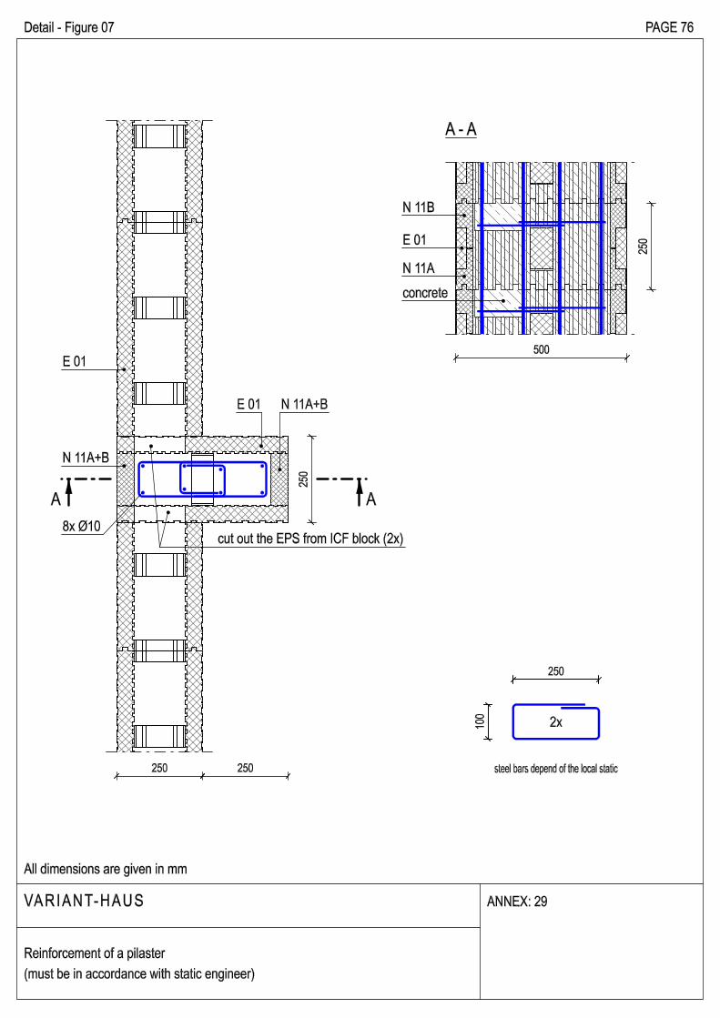
steel bars depend of the local static
E 01
8x Ø10
500
E 01
N 11A
N 11B
N 11A+B
concrete
cut out the EPS from ICF block (2x)
Detail - Figure 07 PAGE 76
VARIANT-HAUS
All dimensions are given in mm
Reinforcement of a pilaster
(must be in accordance with static engineer)
ANNEX: 29
N 11A+B
50
0
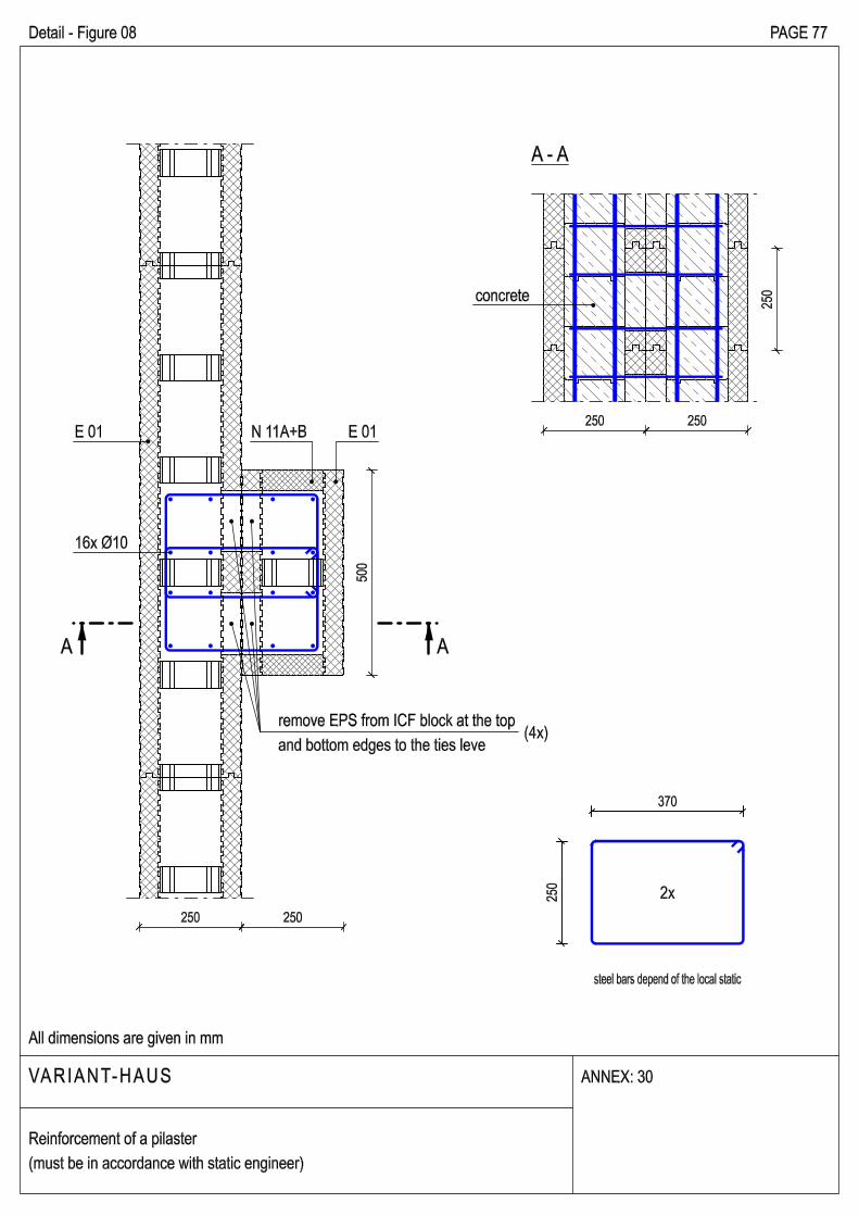
remove EPS from ICF block at the top
and bottom edges to the ties leve
250 250
A - A
A A
250 250
25
0
2x25
0
370
steel bars depend of the local static
concrete
(4x)
Detail - Figure 08 PAGE 77
VARIANT-HAUS
All dimensions are given in mm
ANNEX: 30
Reinforcement of a pilaster
(must be in accordance with static engineer)
16x Ø10
N 11A+B E 01E 01
50
15
05
0
250
25
0
5015050
250 250 250 250
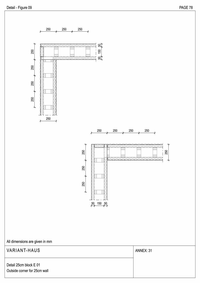
Detail - Figure 09 PAGE 78
VARIANT-HAUS
All dimensions are given in mm
Detail 25cm block E 01
Outside corner for 25cm wall
ANNEX: 31
250 250 2502
50
25
02
50
25
0
25
02
50
25
0
50
15
01
50
350
35
0
50150150
N 20
FIRST LAYER
SECOND LAYER
25
02
50
25
02
50
35
0
100 250 250 250
10
02
50
25
02
50
350 250 250 250
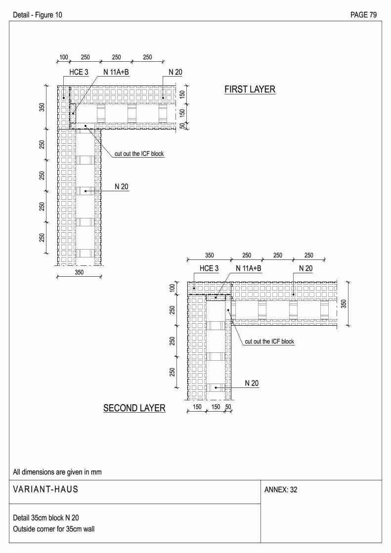
HCE 3 N 20N 11A+B
cut out the ICF block
Detail - Figure 10 PAGE 79
VARIANT-HAUS
All dimensions are given in mm
Detail 35cm block N 20
Outside corner for 35cm wall
ANNEX: 32
N 11A+BHCE 3
cut out the ICF block
N 20
N 20
FIRST LAYER
SECOND LAYER
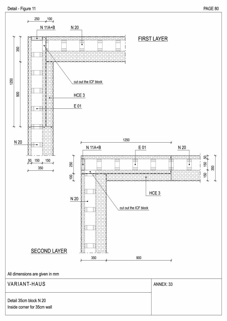
Detail - Figure 11 PAGE 80
VARIANT-HAUS
All dimensions are given in mm
ANNEX: 33
Detail 35cm block N 20
Inside corner for 35cm wall
35
09
00
50 150 150
350
12
50
E 01
50
15
01
50
35
0
1250
350 900
N 20
N 20
25
01
00
250 100
N 11A+B N 20
cut out the ICF block
HCE 3
N 11A+B E 01 N 20
HCE 3
cut out the ICF block
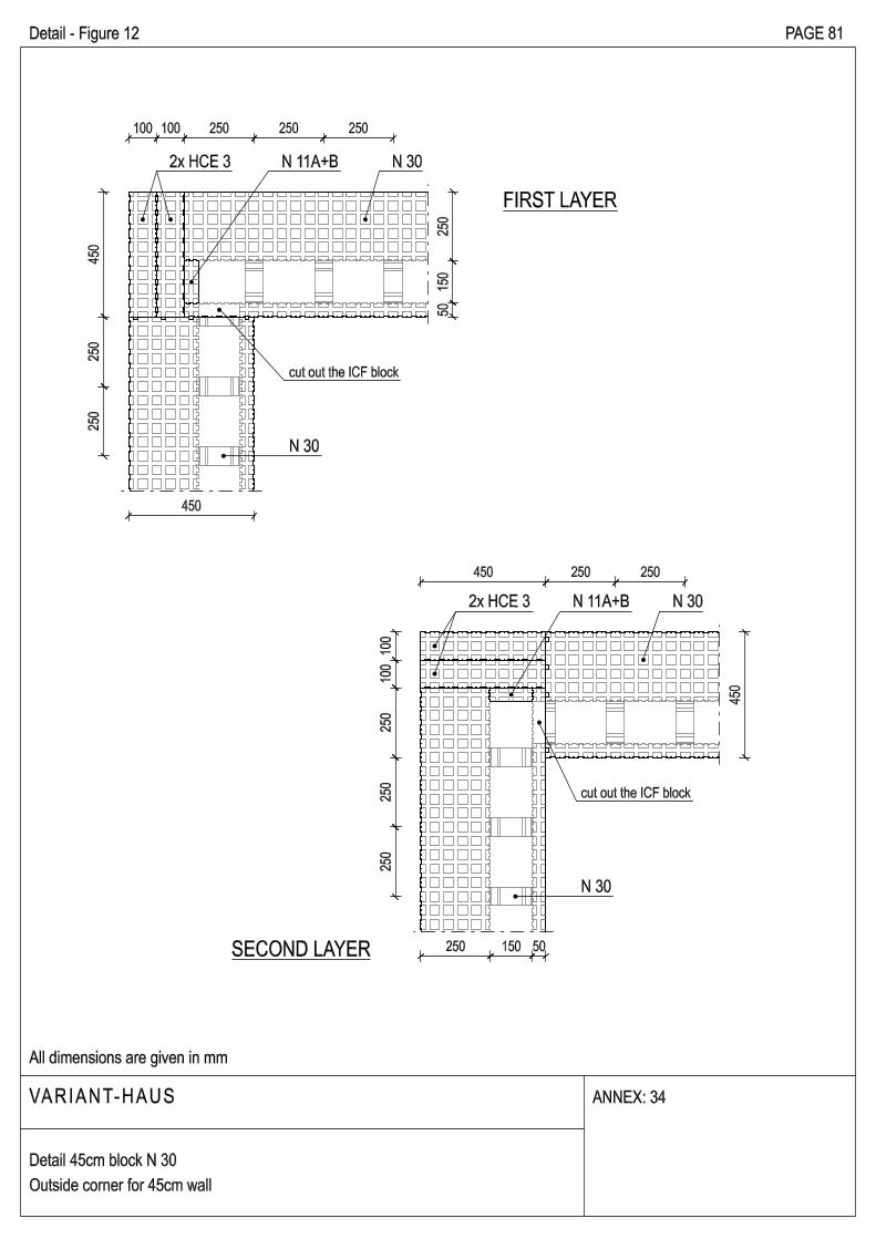
Detail - Figure 12 PAGE 81
VARIANT-HAUS
All dimensions are given in mm
ANNEX: 34
Detail 45cm block N 30
Outside corner for 45cm wall
100 100 250 250 250
25
02
50
45
0
50
15
02
50
450
45
0
50150250
10
01
00
25
02
50
25
0
450 250 250
N 30
FIRST LAYER
SECOND LAYER
2x HCE 3 N 11A+B N 30
cut out the ICF block
N 30
2x HCE 3 N 11A+B N 30
cut out the ICF block
FIRST LAYER
SECOND LAYER
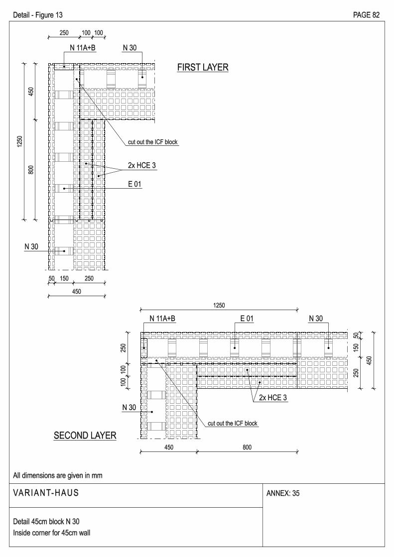
Detail - Figure 13 PAGE 82
VARIANT-HAUS
All dimensions are given in mm
ANNEX: 35
Detail 45cm block N 30
Inside corner for 45cm wall
45
08
00
250 100 100
50 150 250
450
12
50
2x HCE 3
E 01
25
01
00
10
0
50
15
02
50
45
0
1250
N 11A+B
450 800
cut out the ICF block
N 30
N 11A+B N 30
cut out the ICF block
2x HCE 3
E 01 N 30
N 30
15
0
250 (outer wall)
(inn
er w
all)
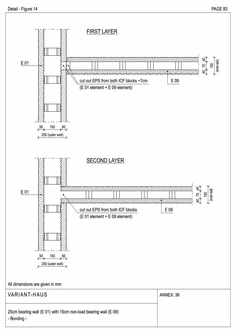
Detail - Figure 14 PAGE 83
VARIANT-HAUS
All dimensions are given in mm
ANNEX: 36
25cm bearing wall (E 01) with 15cm non-load bearing wall (E 09)
- Bonding -
40
70
40
50 150 50
15
0
250 (outer wall)
(inn
er w
all)40
70
40
50 150 50
FIRST LAYER
SECOND LAYER
cut out EPS from both ICF blocks ~7cm
(E 01 element + E 09 element)
E 09
E 01
E 01
cut out EPS from both ICF blocks
(E 01 element + E 09 element)
E 09
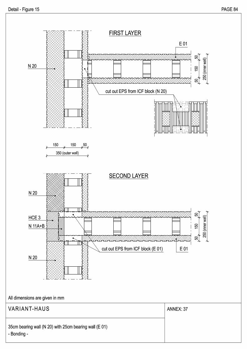
Detail - Figure 15 PAGE 84
VARIANT-HAUS
All dimensions are given in mm
ANNEX: 37
35cm bearing wall (N 20) with 25cm bearing wall (E 01)
- Bonding -
SECOND LAYER
FIRST LAYER
150 150 50
350 (outer wall)
50
15
05
0 25
0 (
inn
er w
all)
50
15
05
0 25
0 (
inn
er w
all)
N 20
cut out EPS from ICF block (N 20)
E 01
N 20
HCE 3
N 11A+B
N 20
cut out EPS from ICF block (E 01) E 01
SECOND LAYER
FIRST LAYER
250 150 50
450 (outer wall)
50
15
05
0 25
0 (
inn
er w
all)
50
15
05
0 25
0 (
inn
er w
all)
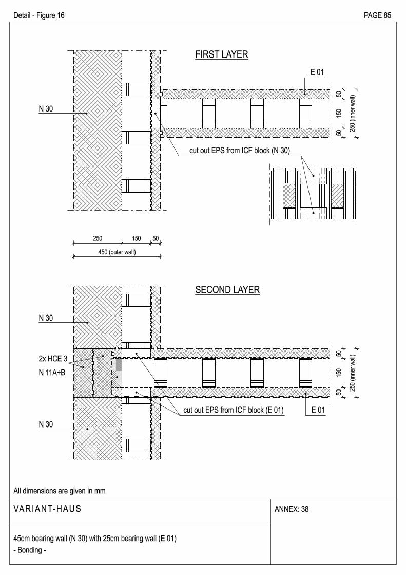
VARIANT-HAUS
All dimensions are given in mm
ANNEX: 38
45cm bearing wall (N 30) with 25cm bearing wall (E 01)
- Bonding -
Detail - Figure 16 PAGE 85
N 30
cut out EPS from ICF block (N 30)
E 01
N 30
2x HCE 3
N 11A+B
N 30
cut out EPS from ICF block (E 01) E 01
VARIANT-HAUS
All dimensions are given in mm
ANNEX: 39
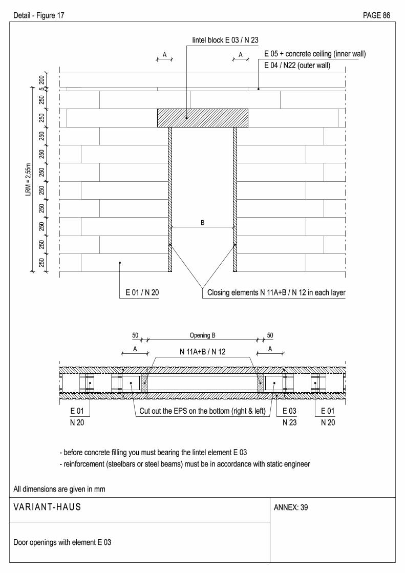
Detail - Figure 17 PAGE 86
Door openings with element E 03
A A
B
Closing elements N 11A+B / N 12 in each layer
50 Opening B 50
A A
Cut out the EPS on the bottom (right & left)
- before concrete filling you must bearing the lintel element E 03
- reinforcement (steelbars or steel beams) must be in accordance with static engineer
N 11A+B / N 12
25
02
50
25
02
50
25
02
50
25
02
50
25
02
50
52
00
LR
M =
2,5
5m
lintel block E 03 / N 23
E 01 / N 20
E 05 + concrete ceiling (inner wall)
E 04 / N22 (outer wall)
E 03
N 23
E 01
N 20
E 01
N 20
A A
B
50 Opening B 50
A AN 11A+B / N 12
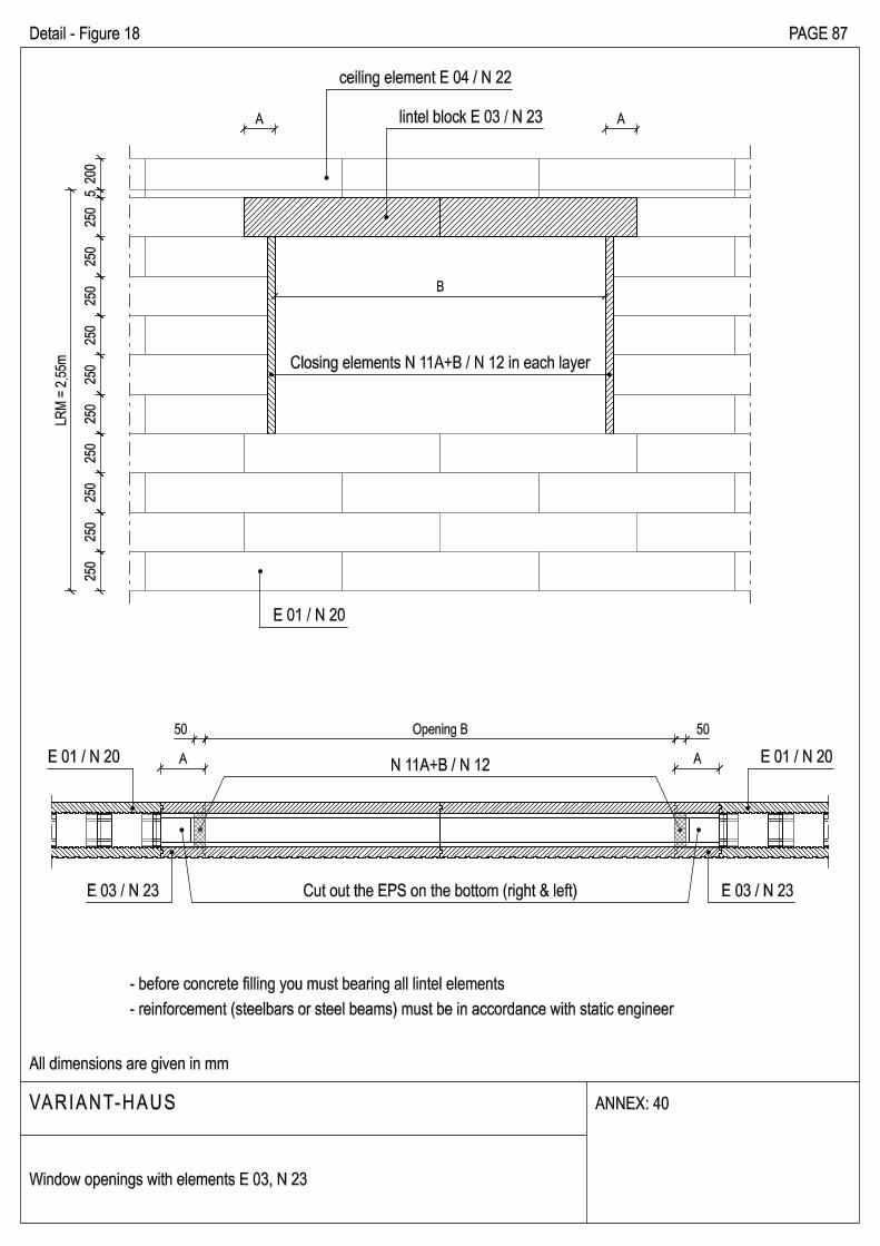
Detail - Figure 18 PAGE 87
VARIANT-HAUS
All dimensions are given in mm
ANNEX: 40
Window openings with elements E 03, N 23
Closing elements N 11A+B / N 12 in each layer
lintel block E 03 / N 23
ceiling element E 04 / N 22
E 01 / N 20
- before concrete filling you must bearing all lintel elements
- reinforcement (steelbars or steel beams) must be in accordance with static engineer
LR
M =
2,5
5m
25
02
50
25
02
50
25
02
50
25
02
50
25
02
50
52
00
E 03 / N 23
E 01 / N 20
Cut out the EPS on the bottom (right & left) E 03 / N 23
E 01 / N 20
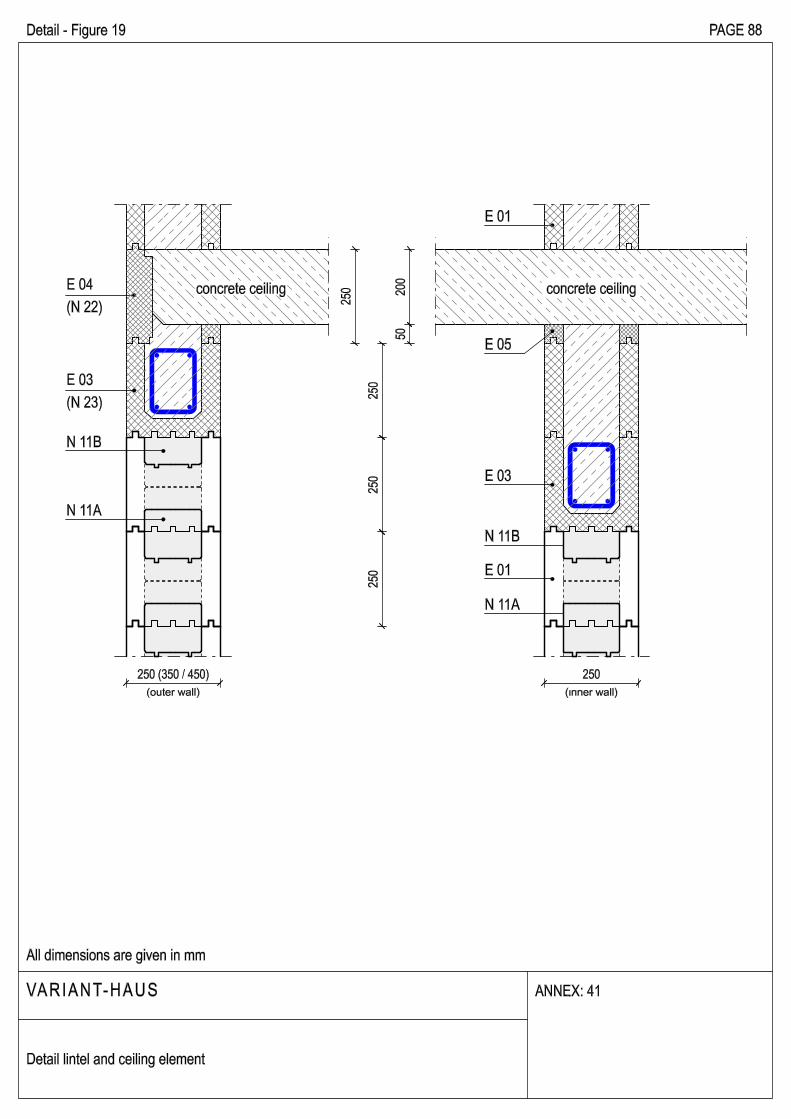
concrete ceiling
E 03
E 01
concrete ceiling
250
E 04
(N 22)
E 03
(N 23)2
00
50
25
02
50
25
0
25
0
250 (350 / 450)
(outer wall) (inner wall)
Detail - Figure 19 PAGE 88
VARIANT-HAUS
All dimensions are given in mm
ANNEX: 41
Detail lintel and ceiling element
E 05
N 11B
N 11A
E 01
N 11A
N 11B
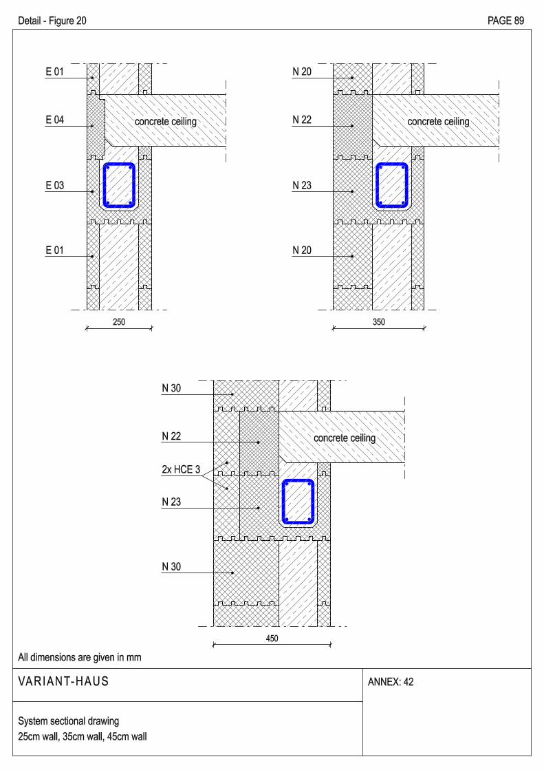
Detail - Figure 20 PAGE 89
VARIANT-HAUS
All dimensions are given in mm
ANNEX: 42
System sectional drawing
25cm wall, 35cm wall, 45cm wall
E 01
E 03
concrete ceiling
N 20
N 23
N 22E 04
E 01 N 20
concrete ceiling
250 350
concrete ceiling
450
N 30
N 30
N 22
2x HCE 3
N 23
250 350 450
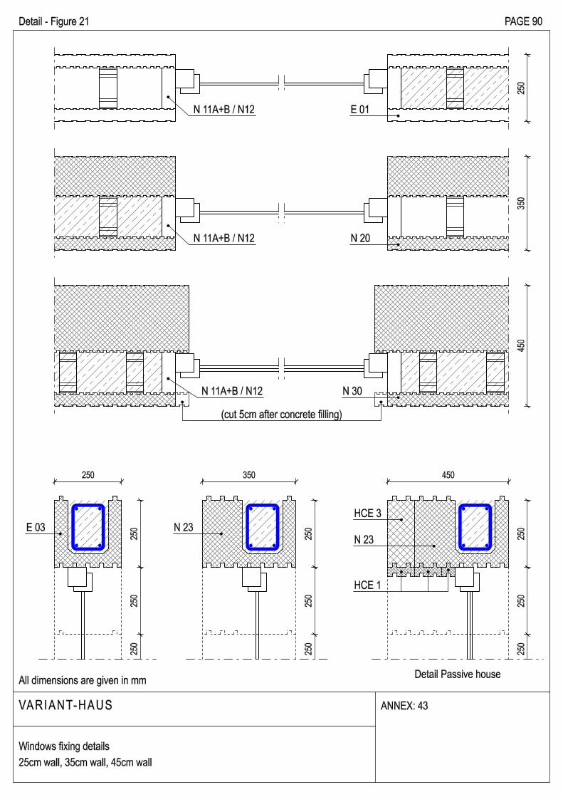
Detail - Figure 21 PAGE 90
VARIANT-HAUS
All dimensions are given in mm
ANNEX: 43
Windows fixing details
25cm wall, 35cm wall, 45cm wall
25
02
50
25
0
25
02
50
25
0
E 03 N 23
HCE 3
N 23 25
02
50
25
04
50
35
02
50
E 01
N 20
N 30
(cut 5cm after concrete filling)
HCE 1
Detail Passive house
N 11A+B / N12
N 11A+B / N12
N 11A+B / N12