e 7 / e 7 d - busse yachtshop · e 7 / e 7 d m u ltifu n c tio n ......
TRANSCRIPT
e 7 / e 7 DMu lt ifu n c t io n d is p la y
Ins ta lla tion ins tructions
ENGLISHDocument number: 87136-2Date : 10-2011
e7 / e7D — User reference
www.busse-yachtshop.de | [email protected]

www.busse-yachtshop.de | [email protected]

Trademark and patents noticeAutohelm, hsb2, RayTech Navigator, Sail Pilot, SeaTalk, SeaTalkNG, SeaTalkHS and Sportpilot are registered trademarks of RaymarineUK Limited. RayTalk, Seahawk, Smartpilot, Pathfinder and Raymarine are registered trademarks of Raymarine Holdings Limited.FLIR is a registered trademark of FLIR Systems, Inc. and/or its subsidiaries.All other trademarks, trade names, or company names referenced herein are used for identification only and are the property oftheir respective owners.This product is protected by patents, design patents, patents pending, or design patents pending.
Fair Use StatementYou may print no more than three copies of this manual for your own use. You may not make any further copies or distribute or use themanual in any other way including without limitation exploiting the manual commercially or giving or selling copies to third parties.Copyright ©2011 Raymarine UK Ltd. All rights reserved.
ENGLISHDocument number: 87136-2Date:10-2011
www.busse-yachtshop.de | [email protected]

www.busse-yachtshop.de | [email protected]
ContentsChapter 1 Important information...............................7TFT Displays....................................................................8Water ingress ...................................................................9Disclaimers ......................................................................9Chart cards and memory cards..........................................9EMC installation guidelines ............................................. 10Suppression ferrites........................................................ 10Connections to other equipment ...................................... 10Declaration of conformity................................................. 10Product disposal ............................................................. 11Warranty registration....................................................... 11IMO and SOLAS............................................................. 11Technical accuracy ......................................................... 11
Chapter 2 Planning the installation ........................132.1 Handbook information ............................................... 142.2 Installation checklist .................................................. 142.3 System integration .................................................... 152.4 System Limits ........................................................... 232.5 Multiple data sources (MDS) overview........................ 232.6 Networking constraints .............................................. 242.7 Typical systems ........................................................ 252.8 System protocols ...................................................... 292.9 Data master.............................................................. 30
2.10 Parts supplied ......................................................... 312.11 Tools required for installation .................................... 32
Chapter 3 Cables and connections.........................333.1 General cabling guidance .......................................... 343.2 Connections overview ............................................... 353.3 Power connection ..................................................... 353.4 Network connections ................................................. 393.5 GPS connection........................................................ 493.6 AIS connection.......................................................... 503.7 Fastheading connection............................................. 513.8 SeaTalkng connections............................................... 513.9 SeaTalk connection ................................................... 553.10 NMEA 0183 connection ........................................... 563.11 NMEA 2000 connection ........................................... 593.12 Video connection..................................................... 603.13 Bluetooth connections ............................................. 613.14 WiFi connections..................................................... 62
Chapter 4 Location and mounting ..........................654.1 Selecting a location ................................................... 664.2 Removing the rear bezel............................................ 684.3 Flush mounting ......................................................... 694.4 Attaching the rear bezel............................................. 70
5www.busse-yachtshop.de | [email protected]
4.5 Bracket (trunnion) mounting....................................... 704.6 Front bezel ............................................................... 72
Chapter 5 System checks........................................755.1 Initial power on test ................................................... 765.2 Designating the data master ...................................... 785.3 GPS check ............................................................... 785.4 Radar check ............................................................. 815.5 Sonar check ............................................................. 835.6 Thermal camera setup and checks............................. 845.7 Enabling autopilot functions ....................................... 865.8 Enabling AIS functions .............................................. 865.9 Language selection ................................................... 87
Chapter 6 Troubleshooting......................................896.1 Troubleshooting ........................................................ 906.2 Power up troubleshooting .......................................... 916.3 Radar troubleshooting ............................................... 926.4 GPS troubleshooting ................................................. 936.5 Sonar troubleshooting ............................................... 946.6 Thermal camera troubleshooting ................................ 966.7 System data troubleshooting...................................... 996.8 Video troubleshooting.............................................. 1006.9 WiFi troubleshooting................................................ 1016.10 Bluetooth troubleshooting ...................................... 1026.11 Touchscreen troubleshooting.................................. 103
6.12 Miscellaneous troubleshooting ............................... 104
Chapter 7 Technical support .................................1057.1 Raymarine customer support ................................... 1067.2 Third-party support.................................................. 107
Chapter 8 Technical specification.........................1098.1 Technical specification............................................. 110
Chapter 9 Options and accessories ..................... 1139.1 Spares and accessories .......................................... 114
Appendix A NMEA 0183 sentences ...................... 115
Appendix B NMEA 2000 sentences ...................... 117
Appendix C Connectors and pinouts ...................120
6 e7 / e7D — Installation instructionswww.busse-yachtshop.de | [email protected]
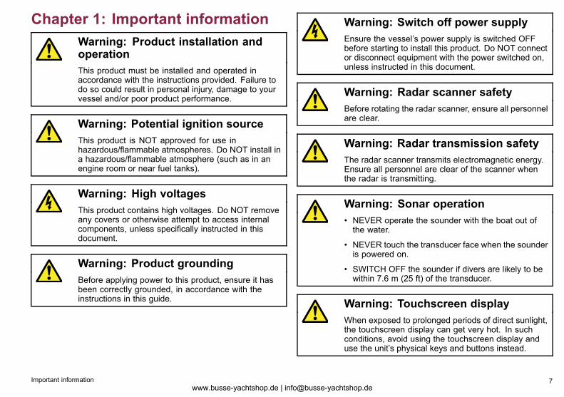
Chapter 1: Important informationWarning: Product installation andoperationThis product must be installed and operated inaccordance with the instructions provided. Failure todo so could result in personal injury, damage to yourvessel and/or poor product performance.
Warning: Potential ignition sourceThis product is NOT approved for use inhazardous/flammable atmospheres. Do NOT install ina hazardous/flammable atmosphere (such as in anengine room or near fuel tanks).
Warning: High voltagesThis product contains high voltages. Do NOT removeany covers or otherwise attempt to access internalcomponents, unless specifically instructed in thisdocument.
Warning: Product groundingBefore applying power to this product, ensure it hasbeen correctly grounded, in accordance with theinstructions in this guide.
Warning: Switch off power supplyEnsure the vessel’s power supply is switched OFFbefore starting to install this product. Do NOT connector disconnect equipment with the power switched on,unless instructed in this document.
Warning: Radar scanner safetyBefore rotating the radar scanner, ensure all personnelare clear.
Warning: Radar transmission safetyThe radar scanner transmits electromagnetic energy.Ensure all personnel are clear of the scanner whenthe radar is transmitting.
Warning: Sonar operation• NEVER operate the sounder with the boat out ofthe water.
• NEVER touch the transducer face when the sounderis powered on.
• SWITCH OFF the sounder if divers are likely to bewithin 7.6 m (25 ft) of the transducer.
Warning: Touchscreen displayWhen exposed to prolonged periods of direct sunlight,the touchscreen display can get very hot. In suchconditions, avoid using the touchscreen display anduse the unit’s physical keys and buttons instead.
Important information 7www.busse-yachtshop.de | [email protected]
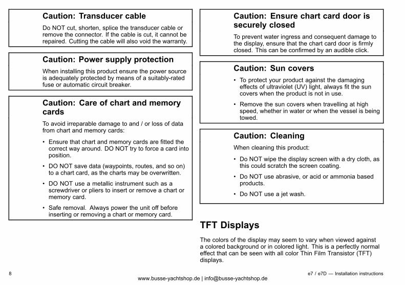
Caution: Transducer cableDo NOT cut, shorten, splice the transducer cable orremove the connector. If the cable is cut, it cannot berepaired. Cutting the cable will also void the warranty.
Caution: Power supply protectionWhen installing this product ensure the power sourceis adequately protected by means of a suitably-ratedfuse or automatic circuit breaker.
Caution: Care of chart and memorycardsTo avoid irreparable damage to and / or loss of datafrom chart and memory cards:
• Ensure that chart and memory cards are fitted thecorrect way around. DO NOT try to force a card intoposition.
• DO NOT save data (waypoints, routes, and so on)to a chart card, as the charts may be overwritten.
• DO NOT use a metallic instrument such as ascrewdriver or pliers to insert or remove a chart ormemory card.
• Safe removal. Always power the unit off beforeinserting or removing a chart or memory card.
Caution: Ensure chart card door issecurely closedTo prevent water ingress and consequent damage tothe display, ensure that the chart card door is firmlyclosed. This can be confirmed by an audible click.
Caution: Sun covers• To protect your product against the damagingeffects of ultraviolet (UV) light, always fit the suncovers when the product is not in use.
• Remove the sun covers when travelling at highspeed, whether in water or when the vessel is beingtowed.
Caution: CleaningWhen cleaning this product:
• Do NOT wipe the display screen with a dry cloth, asthis could scratch the screen coating.
• Do NOT use abrasive, or acid or ammonia basedproducts.
• Do NOT use a jet wash.
TFT DisplaysThe colors of the display may seem to vary when viewed againsta colored background or in colored light. This is a perfectly normaleffect that can be seen with all color Thin Film Transistor (TFT)displays.
8 e7 / e7D — Installation instructionswww.busse-yachtshop.de | [email protected]
In common with all TFT units, the screen may exhibit a few (lessthan 7) wrongly illuminated pixels. These may appear as blackpixels in a light area of the screen or as colored pixels in black areas.
Water ingressWater ingress disclaimerAlthough the waterproof rating capacity of this product meets theIPX6 standard, water intrusion and subsequent equipment failuremay occur if the product is subjected to commercial high-pressurewashing. Raymarine will not warrant products subjected tohigh-pressure washing.
DisclaimersThis product (including the electronic charts) is intended to be usedonly as an aid to navigation. It is designed to facilitate use of officialgovernment charts, not replace them. Only official governmentcharts and notices to mariners contain all the current informationneeded for safe navigation, and the captain is responsible for theirprudent use. It is the user’s responsibility to use official governmentcharts, notices to mariners, caution and proper navigational skillwhen operating this or any other Raymarine product. This productsupports electronic charts provided by third party data supplierswhich may be embedded or stored on memory card. Use of suchcharts is subject to the supplier’s End-User Licence Agreementincluded in the documentation for this product or supplied with thememory card (as applicable).Raymarine does not warrant that this product is error-free or that itis compatible with products manufactured by any person or entityother than Raymarine.This product uses digital chart data, and electronic information fromthe Global Positioning System (GPS) which may contain errors.Raymarine does not warrant the accuracy of such information and
you are advised that errors in such information may cause theproduct to malfunction. Raymarine is not responsible for damagesor injuries caused by your use or inability to use the product, by theinteraction of the product with products manufactured by others, orby errors in chart data or information utilized by the product andsupplied by third parties.
Chart cards and memory cardsMemory cards are used for archiving data and chart cards provideadditional or upgraded charts.
Compatible cardsThe following types of memory or chart card are compatible withyour Raymarine product:
• micro Secure Digital Standard-Capacity (microSDSC)
• micro Secure Digital High-Capacity (microSDHC)
Note: The maximum card capacity supported is 32 GB.
Chart cardsYour product is pre-loaded with electronic charts (worldwide basemap). If you wish to use different chart data, you can insertcompatible chart cards into the unit’s card slot.
Use branded chart cards and memory cardsWhen archiving data, Raymarine recommends the use of qualitybranded memory cards. Some brands of memory card may notwork in your unit. Please contact customer support for a list ofrecommended cards.
Important information 9www.busse-yachtshop.de | [email protected]
EMC installation guidelinesRaymarine equipment and accessories conform to the appropriateElectromagnetic Compatibility (EMC) regulations, to minimizeelectromagnetic interference between equipment and minimize theeffect such interference could have on the performance of yoursystemCorrect installation is required to ensure that EMC performance isnot compromised.For optimum EMC performance we recommend that whereverpossible:
• Raymarine equipment and cables connected to it are:
– At least 1 m (3 ft) from any equipment transmitting or cablescarrying radio signals e.g. VHF radios, cables and antennas.In the case of SSB radios, the distance should be increasedto 7 ft (2 m).
– More than 2 m (7 ft) from the path of a radar beam. A radarbeam can normally be assumed to spread 20 degrees aboveand below the radiating element.
• The product is supplied from a separate battery from that usedfor engine start. This is important to prevent erratic behaviorand data loss which can occur if the engine start does not havea separate battery.
• Raymarine specified cables are used.
• Cables are not cut or extended, unless doing so is detailed inthe installation manual.
Note: Where constraints on the installation prevent any ofthe above recommendations, always ensure the maximumpossible separation between different items of electricalequipment, to provide the best conditions for EMC performancethroughout the installation
Suppression ferritesRaymarine cables may be fitted with suppression ferrites. Theseare important for correct EMC performance. If a ferrite has to beremoved for any purpose (e.g. installation or maintenance), it mustbe replaced in the original position before the product is used.Use only ferrites of the correct type, supplied by Raymarineauthorized dealers.
Connections to other equipmentRequirement for ferrites on non-Raymarine cablesIf your Raymarine equipment is to be connected to other equipmentusing a cable not supplied by Raymarine, a suppression ferriteMUST always be attached to the cable near the Raymarine unit.
Declaration of conformityRaymarine Ltd. declares that this product is in compliance with theessential requirements of EMC directive 2004/108/EC.The original Declaration of Conformity certificate may be viewed onthe relevant product page at www.raymarine.com
10 e7 / e7D — Installation instructionswww.busse-yachtshop.de | [email protected]
Product disposalDispose of this product in accordance with the WEEE Directive.
The Waste Electrical and Electronic Equipment (WEEE)Directive requires the recycling of waste electrical and electronicequipment. Whilst the WEEE Directive does not apply to someRaymarine products, we support its policy and ask you to be awareof how to dispose of this product.
Warranty registrationTo register your Raymarine product ownership, please visitwww.raymarine.com and register online.It is important that you register your product to receive full warrantybenefits. Your unit package includes a bar code label indicating theserial number of the unit. You will need this serial number whenregistering your product online. You should retain the label for futurereference.
IMO and SOLASThe equipment described within this document is intended for useon leisure marine boats and workboats not covered by InternationalMaritime Organization (IMO) and Safety of Life at Sea (SOLAS)Carriage Regulations.
Technical accuracyTo the best of our knowledge, the information in this document wascorrect at the time it was produced. However, Raymarine cannotaccept liability for any inaccuracies or omissions it may contain. Inaddition, our policy of continuous product improvement may changespecifications without notice. As a result, Raymarine cannot acceptliability for any differences between the product and this document.
Important information 11www.busse-yachtshop.de | [email protected]

12 e7 / e7D — Installation instructionswww.busse-yachtshop.de | [email protected]
Chapter 2: Planning the installation
Chapter contents• 2.1 Handbook information on page 14
• 2.2 Installation checklist on page 14
• 2.3 System integration on page 15
• 2.4 System Limits on page 23
• 2.5 Multiple data sources (MDS) overview on page 23
• 2.6 Networking constraints on page 24
• 2.7 Typical systems on page 25
• 2.8 System protocols on page 29
• 2.9 Data master on page 30
• 2.10 Parts supplied on page 31
• 2.11 Tools required for installation on page 32
Planning the installation 13www.busse-yachtshop.de | [email protected]
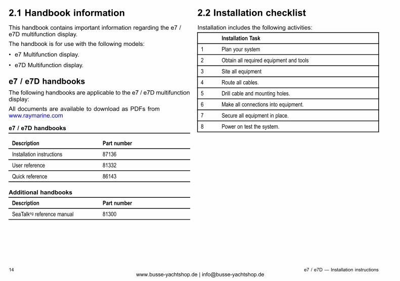
2.1 Handbook informationThis handbook contains important information regarding the e7 /e7D multifunction display.The handbook is for use with the following models:
• e7 Multifunction display.
• e7D Multifunction display.
e7 / e7D handbooksThe following handbooks are applicable to the e7 / e7D multifunctiondisplay:All documents are available to download as PDFs fromwww.raymarine.com
e7 / e7D handbooks
Description Part number
Installation instructions 87136
User reference 81332
Quick reference 86143
Additional handbooks
Description Part number
SeaTalkng reference manual 81300
2.2 Installation checklistInstallation includes the following activities:
Installation Task
1 Plan your system
2 Obtain all required equipment and tools
3 Site all equipment
4 Route all cables.
5 Drill cable and mounting holes.
6 Make all connections into equipment.
7 Secure all equipment in place.
8 Power on test the system.
14 e7 / e7D — Installation instructionswww.busse-yachtshop.de | [email protected]
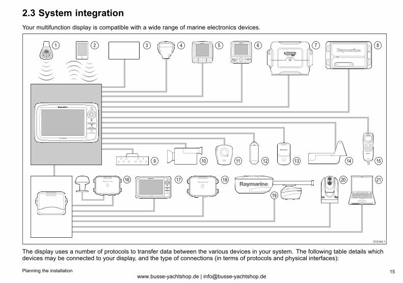
2.3 System integrationYour multifunction display is compatible with a wide range of marine electronics devices.
RAY240
1 2 85 6 73
15109 11 12 13 14
4
1716 18
19
20 21
D12142-1
SMARTPILOT
The display uses a number of protocols to transfer data between the various devices in your system. The following table details whichdevices may be connected to your display, and the type of connections (in terms of protocols and physical interfaces):
Planning the installation 15www.busse-yachtshop.de | [email protected]
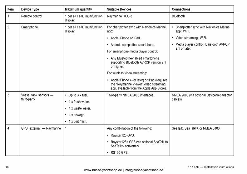
Item Device Type Maximum quantity Suitable Devices Connections
1 Remote control 1 per e7 / e7D multifunctiondisplay.
Raymarine RCU-3 Bluetooth
2 Smartphone 1 per e7 / e7D multifunctiondisplay.
For chartplotter sync with Navionics Marineapp:
• Apple iPhone or iPad.
• Android-compatible smartphone.
For smartphone media player control:
• Any Bluetooth-enabled smartphonesupporting Bluetooth AVRCP version 2.1or higher.
For wireless video streaming:
• Apple iPhone 4 (or later) or iPad (requiresthe “Raymarine Viewer” video streamingapp, available from the Apple App Store).
• Chartplotter sync with Navionics Marineapp: WiFi.
• Video streaming: WiFi.
• Media player control: Bluetooth AVRCP2.1 or later.
3 Vessel tank sensors —third-party
• Up to 3 x fuel.
• 1 x fresh water.
• 1 x waste water.
• 1 x sewage.
• 1 x bait / fish.
Third-party NMEA 2000 interfaces. NMEA 2000 (via optional DeviceNet adaptorcables).
4 GPS (external) — Raymarine 1 Any combination of the following:
• Raystar125 GPS.
• Raystar125+ GPS (via optional SeaTalk toSeaTalkng converter).
• RS130 GPS.
SeaTalk, SeaTalkng, or NMEA 0183.
16 e7 / e7D — Installation instructionswww.busse-yachtshop.de | [email protected]
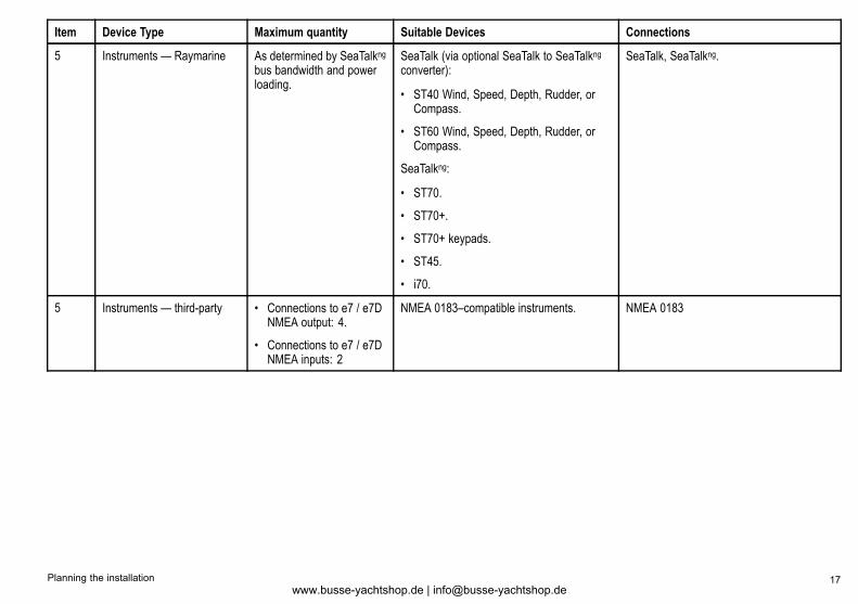
Item Device Type Maximum quantity Suitable Devices Connections
5 Instruments — Raymarine As determined by SeaTalkngbus bandwidth and powerloading.
SeaTalk (via optional SeaTalk to SeaTalkngconverter):
• ST40 Wind, Speed, Depth, Rudder, orCompass.
• ST60 Wind, Speed, Depth, Rudder, orCompass.
SeaTalkng:
• ST70.
• ST70+.
• ST70+ keypads.
• ST45.
• i70.
SeaTalk, SeaTalkng.
5 Instruments — third-party • Connections to e7 / e7DNMEA output: 4.
• Connections to e7 / e7DNMEA inputs: 2
NMEA 0183–compatible instruments. NMEA 0183
Planning the installation 17www.busse-yachtshop.de | [email protected]
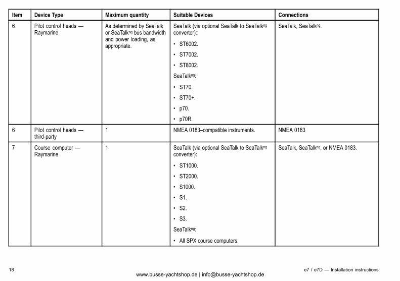
Item Device Type Maximum quantity Suitable Devices Connections
6 Pilot control heads —Raymarine
As determined by SeaTalkor SeaTalkng bus bandwidthand power loading, asappropriate.
SeaTalk (via optional SeaTalk to SeaTalkngconverter)::
• ST6002.
• ST7002.
• ST8002.
SeaTalkng:
• ST70.
• ST70+.
• p70.
• p70R.
SeaTalk, SeaTalkng.
6 Pilot control heads —third-party
1 NMEA 0183–compatible instruments. NMEA 0183
7 Course computer —Raymarine
1 SeaTalk (via optional SeaTalk to SeaTalkngconverter):
• ST1000.
• ST2000.
• S1000.
• S1.
• S2.
• S3.
SeaTalkng:
• All SPX course computers.
SeaTalk, SeaTalkng, or NMEA 0183.
18 e7 / e7D — Installation instructionswww.busse-yachtshop.de | [email protected]
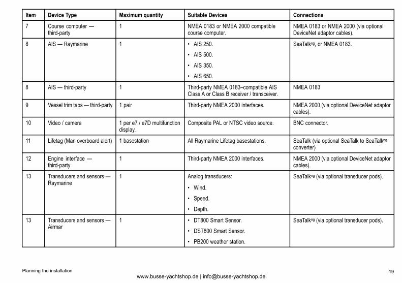
Item Device Type Maximum quantity Suitable Devices Connections
7 Course computer —third-party
1 NMEA 0183 or NMEA 2000 compatiblecourse computer.
NMEA 0183 or NMEA 2000 (via optionalDeviceNet adaptor cables).
8 AIS — Raymarine 1 • AIS 250.
• AIS 500.
• AIS 350.
• AIS 650.
SeaTalkng, or NMEA 0183.
8 AIS — third-party 1 Third-party NMEA 0183–compatible AISClass A or Class B receiver / transceiver.
NMEA 0183
9 Vessel trim tabs — third-party 1 pair Third-party NMEA 2000 interfaces. NMEA 2000 (via optional DeviceNet adaptorcables).
10 Video / camera 1 per e7 / e7D multifunctiondisplay.
Composite PAL or NTSC video source. BNC connector.
11 Lifetag (Man overboard alert) 1 basestation All Raymarine Lifetag basestations. SeaTalk (via optional SeaTalk to SeaTalkngconverter)
12 Engine interface —third-party
1 Third-party NMEA 2000 interfaces. NMEA 2000 (via optional DeviceNet adaptorcables).
13 Transducers and sensors —Raymarine
1 Analog transducers:
• Wind.
• Speed.
• Depth.
SeaTalkng (via optional transducer pods).
13 Transducers and sensors —Airmar
1 • DT800 Smart Sensor.
• DST800 Smart Sensor.
• PB200 weather station.
SeaTalkng (via optional transducer pods).
Planning the installation 19www.busse-yachtshop.de | [email protected]
Item Device Type Maximum quantity Suitable Devices Connections
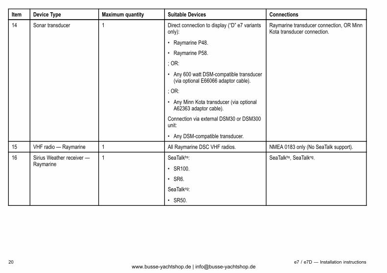
14 Sonar transducer 1 Direct connection to display (“D” e7 variantsonly):
• Raymarine P48.
• Raymarine P58.
; OR:
• Any 600 watt DSM-compatible transducer(via optional E66066 adaptor cable).
; OR:
• Any Minn Kota transducer (via optionalA62363 adaptor cable).
Connection via external DSM30 or DSM300unit:
• Any DSM-compatible transducer.
Raymarine transducer connection, OR MinnKota transducer connection.
15 VHF radio — Raymarine 1 All Raymarine DSC VHF radios. NMEA 0183 only (No SeaTalk support).
16 Sirius Weather receiver —Raymarine
1 SeaTalkhs:
• SR100.
• SR6.
SeaTalkng:
• SR50.
SeaTalkhs, SeaTalkng.
20 e7 / e7D — Installation instructionswww.busse-yachtshop.de | [email protected]
Item Device Type Maximum quantity Suitable Devices Connections
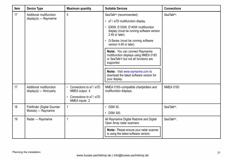
17 Additional multifunctiondisplay(s) — Raymarine
5 SeaTalkhs (recommended):
• e7 / e7D multifunction display.
• E90W, E120W, E140W multifunctiondisplay (must be running software version2.49 or later).
• G-Series (must be running softwareversion 4.49 or later).
Note: You can connect Raymarinemultifunction displays using NMEA 0183or SeaTalkng but not all functions aresupported.
Note: Visit www.raymarine.com todownload the latest software version foryour display.
SeaTalkhs.
17 Additional multifunctiondisplay(s) — third-party
• Connections to e7 / e7DNMEA output: 4.
• Connections to e7 / e7DNMEA inputs: 2
NMEA 0183–compatible chartplotters andmultifunction displays.
NMEA 0183
18 Fishfinder (Digital SounderModule) — Raymarine
1 • DSM 30.
• DSM 300.
SeaTalkhs.
19 Radar — Raymarine 1 All Raymarine Digital Radome and DigitalOpen Array radar scanners.
Note: Please ensure your radar scanneris using the latest software version.
SeaTalkhs.
Planning the installation 21www.busse-yachtshop.de | [email protected]
Item Device Type Maximum quantity Suitable Devices Connections
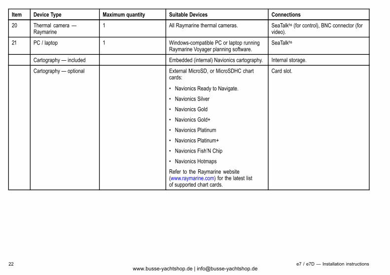
20 Thermal camera —Raymarine
1 All Raymarine thermal cameras. SeaTalkhs (for control), BNC connector (forvideo).
21 PC / laptop 1 Windows-compatible PC or laptop runningRaymarine Voyager planning software.
SeaTalkhs
Cartography — included Embedded (internal) Navionics cartography. Internal storage.
Cartography — optional External MicroSD, or MicroSDHC chartcards:
• Navionics Ready to Navigate.
• Navionics Silver
• Navionics Gold
• Navionics Gold+
• Navionics Platinum
• Navionics Platinum+
• Navionics Fish’N Chip
• Navionics Hotmaps
Refer to the Raymarine website(www.raymarine.com) for the latest listof supported chart cards.
Card slot.
22 e7 / e7D — Installation instructionswww.busse-yachtshop.de | [email protected]
2.4 System LimitsThe following limits apply to the number of system components thatcan be connected in an e7 / e7D system.
Component Maximum
Maximum number of SeaTalkhsdevices
25
Maximum number of SeaTalkngdevices
50
e7 / e7D multifunction displays 6
2.5 Multiple data sources (MDS) overviewInstallations that include multiple instances of data sources cancause data conflicts. An example is an installation featuring morethan one source of GPS data.MDS enables you to manage conflicts involving the following typesof data:
• GPS Position.
• Heading.
• Depth.
• Speed.
• Wind.
Typically this exercise is completed as part of the initial installation,or when new equipment is added.If this exercise is NOT completed the system will automaticallyattempt to resolve data conflicts. However, this may result in thesystem choosing a source of data that you do not want to use.If MDS is available the system can list the available data sourcesand allow you to select your preferred data source. For MDS to beavailable all products in the system that use the data sources listedabove must be MDS-compliant. The system can list any productsthat are NOT compliant. It may be necessary to upgrade thesoftware for these non-compliant products to make them compliant.Visit the Raymarine website (www.raymarine.com) to obtain thelatest software for your products. If MDS-compliant software is notavailable and you do NOT want the system to automatically attemptto resolve data conflicts, any non-compliant product(s) can beremoved or replaced to ensure the entire system is MDS-compliant.
Planning the installation 23www.busse-yachtshop.de | [email protected]
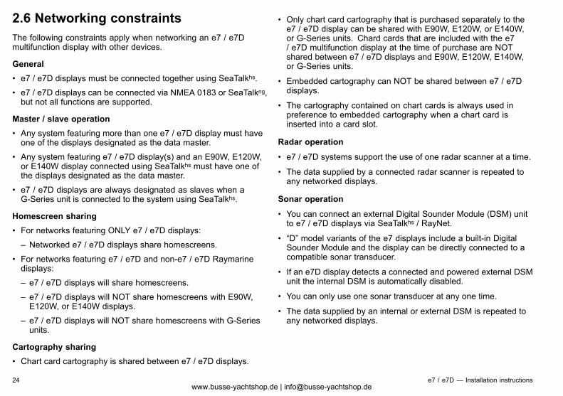
2.6 Networking constraintsThe following constraints apply when networking an e7 / e7Dmultifunction display with other devices.
General• e7 / e7D displays must be connected together using SeaTalkhs.
• e7 / e7D displays can be connected via NMEA 0183 or SeaTalkng,but not all functions are supported.
Master / slave operation• Any system featuring more than one e7 / e7D display must haveone of the displays designated as the data master.
• Any system featuring e7 / e7D display(s) and an E90W, E120W,or E140W display connected using SeaTalkhs must have one ofthe displays designated as the data master.
• e7 / e7D displays are always designated as slaves when aG-Series unit is connected to the system using SeaTalkhs.
Homescreen sharing• For networks featuring ONLY e7 / e7D displays:
– Networked e7 / e7D displays share homescreens.
• For networks featuring e7 / e7D and non-e7 / e7D Raymarinedisplays:
– e7 / e7D displays will share homescreens.
– e7 / e7D displays will NOT share homescreens with E90W,E120W, or E140W displays.
– e7 / e7D displays will NOT share homescreens with G-Seriesunits.
Cartography sharing• Chart card cartography is shared between e7 / e7D displays.
• Only chart card cartography that is purchased separately to thee7 / e7D display can be shared with E90W, E120W, or E140W,or G-Series units. Chard cards that are included with the e7/ e7D multifunction display at the time of purchase are NOTshared between e7 / e7D displays and E90W, E120W, E140W,or G-Series units.
• Embedded cartography can NOT be shared between e7 / e7Ddisplays.
• The cartography contained on chart cards is always used inpreference to embedded cartography when a chart card isinserted into a card slot.
Radar operation
• e7 / e7D systems support the use of one radar scanner at a time.
• The data supplied by a connected radar scanner is repeated toany networked displays.
Sonar operation
• You can connect an external Digital Sounder Module (DSM) unitto e7 / e7D displays via SeaTalkhs / RayNet.
• “D” model variants of the e7 displays include a built-in DigitalSounder Module and the display can be directly connected to acompatible sonar transducer.
• If an e7D display detects a connected and powered external DSMunit the internal DSM is automatically disabled.
• You can only use one sonar transducer at any one time.
• The data supplied by an internal or external DSM is repeated toany networked displays.
24 e7 / e7D — Installation instructionswww.busse-yachtshop.de | [email protected]
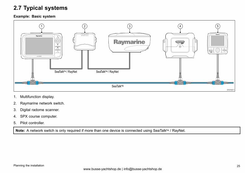
2.7 Typical systemsExample: Basic system
SMARTPILOT
D12143-1
1 2 3 4 5
SeaTalkng
SeaTalkhs / RayNet SeaTalkhs / RayNet
1. Multifunction display.
2. Raymarine network switch.
3. Digital radome scanner.
4. SPX course computer.
5. Pilot controller.
Note: A network switch is only required if more than one device is connected using SeaTalkhs / RayNet.
Planning the installation 25www.busse-yachtshop.de | [email protected]
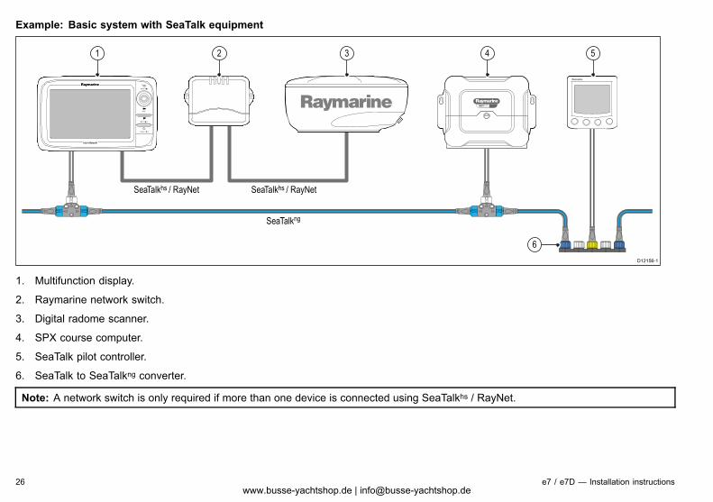
Example: Basic system with SeaTalk equipment
SMARTPILOT
D12156-1
1 2 3 4
SeaTalkng
5
6
SeaTalkhs / RayNet SeaTalkhs / RayNet
1. Multifunction display.
2. Raymarine network switch.
3. Digital radome scanner.
4. SPX course computer.
5. SeaTalk pilot controller.
6. SeaTalk to SeaTalkng converter.
Note: A network switch is only required if more than one device is connected using SeaTalkhs / RayNet.
26 e7 / e7D — Installation instructionswww.busse-yachtshop.de | [email protected]
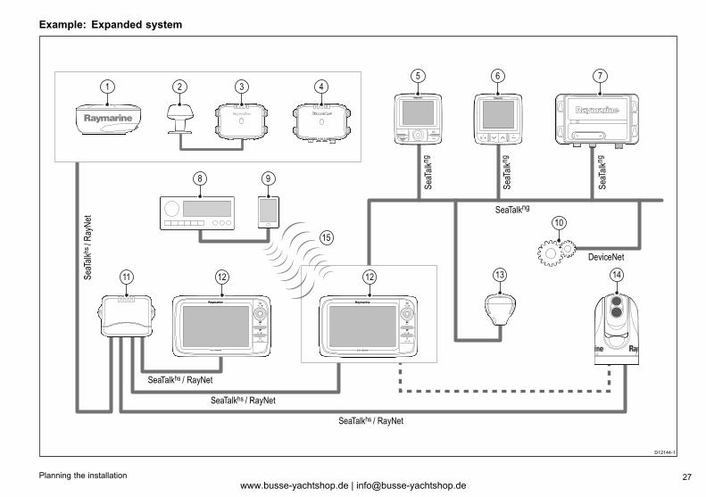
Example: Expanded system
D12144-1
SeaTalkhs / RayNet
SeaTalkhs / RayNet
SeaTalkhs / RayNet
SeaT
alkh
s / R
ayN
et
DeviceNet
SeaTalkng
SeaT
alkn
g
SeaT
alkn
g
SeaT
alkn
g
51
8
11 12 12 14
9
15
2 3 46
13
10
7
Planning the installation 27www.busse-yachtshop.de | [email protected]

1. Digital radome scanner.
2. Weather sensor.
3. Sirius weather receiver.
4. Digital Sounder Module (DSM).
5. Pilot controller.
6. Instrument.
7. AIS receiver / transceiver.
8. Audio system.
9. Smartphone.
10. DeviceNet spur (for NMEA 2000 devices).
11. Raymarine network switch.
12. Multifunction display.
13. GPS receiver.
14. Thermal camera.
15. Wireless connection.
28 e7 / e7D — Installation instructionswww.busse-yachtshop.de | [email protected]
2.8 System protocolsYour Multifunction Display can connect to various instruments anddisplays to share information and so improve the functionality ofthe system. These connections may be made using a number ofdifferent protocols. Fast and accurate data collection and transfer isachieved by using a combination of the following data protocols:
• SeaTalkhs
• SeaTalkng
• NMEA 2000
• SeaTalk
• NMEA 0183
Note: You may find that your system does not use all of theconnection types or instrumentation described in this section.
SeaTalkhsSeaTalkhs is an ethernet based marine network. This high speedprotocol allows compatible equipment to communicate rapidly andshare large amounts of data.Information shared using the SeaTalkhs network includes:
• Shared cartography (between compatible displays).
• Digital radar data.
• Sonar data.
SeatalkngSeaTalkng (Next Generation) is an enhanced protocol for connectionof compatible marine instruments and equipment. It replaces theolder SeaTalk and SeaTalk2 protocols.SeaTalkng utilizes a single backbone to which compatibleinstruments connect using a spur. Data and power are carried withinthe backbone. Devices that have a low draw can be powered fromthe network, although high current equipment will need to have aseparate power connection.SeaTalkng is a proprietary extension to NMEA 2000 and the provenCAN bus technology. Compatible NMEA 2000 and SeaTalk /SeaTalk2 devices can also be connected using the appropriateinterfaces or adaptor cables as required.
NMEA 2000NMEA 2000 offers significant improvements over NMEA 0183, mostnotably in speed and connectivity. Up to 50 units can simultaneouslytransmit and receive on a single physical bus at any one time,with each node being physically addressable. The standardwas specifically intended to allow for a whole network of marineelectronics from any manufacturer to communicate on a commonbus via standardized message types and formats.
SeaTalkSeaTalk is a protocol which enables compatible instruments toconnect to each other and share data.The SeaTalk cable system is used to connect compatibleinstruments and equipment. The cable carries power and data andenables connection without the need for a central processor.Additional instruments and functions can be added to a SeaTalksystem, simply by plugging them into the network. SeaTalkequipment can also communicate with other non-SeaTalk equipmentvia the NMEA 0183 standard, provided a suitable interface is used.
Planning the installation 29www.busse-yachtshop.de | [email protected]
NMEA 0183The NMEA 0183 Data Interface Standard was developed bythe National Marine Electronics Association of America. It is aninternational standard to enable equipment from many differentmanufacturers to be connected together and share information.The NMEA 0183 standard carries similar information to SeaTalk.However it has the important difference that one cable will onlycarry information in one direction. For this reason NMEA 0183 isgenerally used to connect a data receiver and a transmitter together,e.g. a compass sensor transmitting heading to a radar display. Thisinformation is passed in ‘sentences’, each of which has a threeletter sentence identifier. It is therefore important when checkingcompatibility between items that the same sentence identifiers areused some examples of which are:
• VTG - carries Course and Speed Over Ground data.
• GLL - carries latitude and longitude.
• DBT - carries water depth.
• MWV - carries relative wind angle and wind speed data.
NMEA baud ratesThe NMEA 0183 standard operates at a number of differentspeeds, depending upon the particular requirement or equipmentcapabilities. Typical examples are:
• 4800 baud rate. Used for general purpose communications,including FastHeading data.
• 9600 baud rate. Used for Navtex.
• 38400 baud rate. Used for AIS and other high speed applications.
2.9 Data masterAny system containing more than one networked multifunctiondisplay must have a designated data master.The data master is the display which serves as a primary sourceof data for all displays, it also handles all external sources ofinformation. For example the displays may require headinginformation from the autopilot and GPS systems, usually receivedthrough a SeaTalkng or NMEA connection. The data master is thedisplay to which the SeaTalk, NMEA and any other data connectionsare made, it then bridges the data to the SeaTalkhs network andany compatible repeat displays. Information shared by the datamaster includes:
• Cartography
• Routes and waypoints
• Radar
• Sonar
• Data received from the autopilot, instruments, the engine andother external sources.
Your system may be wired for redundancy with data connectionsmade to repeat displays. However these connections will onlybecome active in the event of a fault and/or reassignment of thedata master.
30 e7 / e7D — Installation instructionswww.busse-yachtshop.de | [email protected]
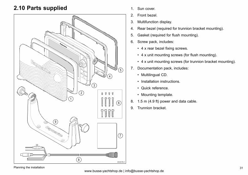
2.10 Parts supplied
D12170-1
1
2
8
3
4
5
7
9
6
1. Sun cover.
2. Front bezel.
3. Multifunction display.
4. Rear bezel (required for trunnion bracket mounting).
5. Gasket (required for flush mounting).
6. Screw pack, includes:
• 4 x rear bezel fixing screws.
• 4 x unit mounting screws (for flush mounting).
• 4 x unit mounting screws (for trunnion bracket mounting).
7. Documentation pack, includes:
• Multilingual CD.
• Installation instructions.
• Quick reference.
• Mounting template.
8. 1.5 m (4.9 ft) power and data cable.
9. Trunnion bracket.
Planning the installation 31www.busse-yachtshop.de | [email protected]
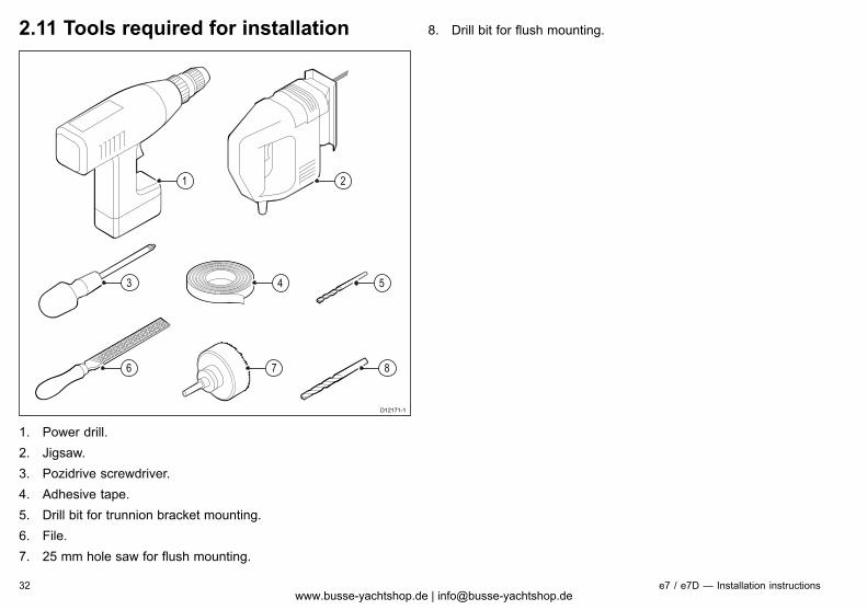
2.11 Tools required for installation
D12171-1
1
4 53
876
2
1. Power drill.2. Jigsaw.3. Pozidrive screwdriver.4. Adhesive tape.5. Drill bit for trunnion bracket mounting.6. File.7. 25 mm hole saw for flush mounting.
8. Drill bit for flush mounting.
32 e7 / e7D — Installation instructionswww.busse-yachtshop.de | [email protected]
Chapter 3: Cables and connections
Chapter contents• 3.1 General cabling guidance on page 34
• 3.2 Connections overview on page 35
• 3.3 Power connection on page 35
• 3.4 Network connections on page 39
• 3.5 GPS connection on page 49
• 3.6 AIS connection on page 50
• 3.7 Fastheading connection on page 51
• 3.8 SeaTalkng connections on page 51
• 3.9 SeaTalk connection on page 55
• 3.10 NMEA 0183 connection on page 56
• 3.11 NMEA 2000 connection on page 59
• 3.12 Video connection on page 60
• 3.13 Bluetooth connections on page 61
• 3.14 WiFi connections on page 62
Cables and connections 33www.busse-yachtshop.de | [email protected]
3.1 General cabling guidance
Cable types and lengthIt is important to use cables of the appropriate type and length
• Unless otherwise stated use only standard cables of the correcttype, supplied by Raymarine.
• Ensure that any non-Raymarine cables are of the correct qualityand gauge. For example, longer power cable runs may requirelarger wire gauges to minimize voltage drop along the run.
Routing cablesCables must be routed correctly, to maximize performance andprolong cable life.
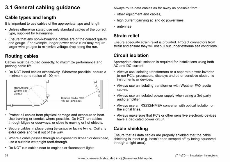
• Do NOT bend cables excessively. Wherever possible, ensure aminimum bend radius of 100 mm.
Minimum bend of cable100 mm (4 in) radius
Minimum bend200 mm (8 in)diameter
• Protect all cables from physical damage and exposure to heat.Use trunking or conduit where possible. Do NOT run cablesthrough bilges or doorways, or close to moving or hot objects.
• Secure cables in place using tie-wraps or lacing twine. Coil anyextra cable and tie it out of the way.
• Where a cable passes through an exposed bulkhead or deckhead,use a suitable watertight feed-through.
• Do NOT run cables near to engines or fluorescent lights.
Always route data cables as far away as possible from:
• other equipment and cables,
• high current carrying ac and dc power lines,
• antennae.
Strain reliefEnsure adequate strain relief is provided. Protect connectors fromstrain and ensure they will not pull out under extreme sea conditions.
Circuit isolationAppropriate circuit isolation is required for installations using bothAC and DC current:
• Always use isolating transformers or a separate power-inverterto run PC’s, processors, displays and other sensitive electronicinstruments or devices.
• Always use an isolating transformer with Weather FAX audiocables.
• Always use an isolated power supply when using a 3rd partyaudio amplifier.
• Always use an RS232/NMEA converter with optical isolation onthe signal lines.
• Always make sure that PC’s or other sensitive electronic deviceshave a dedicated power circuit.
Cable shieldingEnsure that all data cables are properly shielded that the cableshielding is intact (e.g. hasn’t been scraped off by being squeezedthrough a tight area).
34 e7 / e7D — Installation instructionswww.busse-yachtshop.de | [email protected]
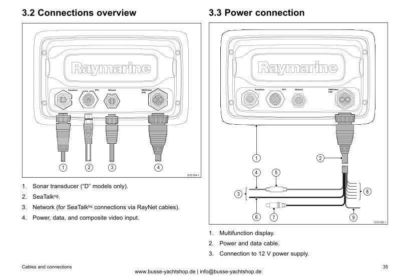
3.2 Connections overview
D12154-1
1 2 3 4
1. Sonar transducer (“D” models only).
2. SeaTalkng.
3. Network (for SeaTalkhs connections via RayNet cables).
4. Power, data, and composite video input.
3.3 Power connection
D12155-1
83
1
6
4 5
2
7 9
1. Multifunction display.
2. Power and data cable.
3. Connection to 12 V power supply.
Cables and connections 35www.busse-yachtshop.de | [email protected]
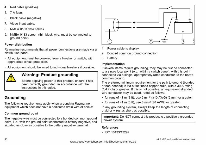
4. Red cable (positive).
5. 7 A fuse.
6. Black cable (negative).
7. Video input cable.
8. NMEA 0183 data cables.
9. NMEA 0183 screen (thin black wire; must be connected toground point).
Power distributionRaymarine recommends that all power connections are made via adistribution panel.
• All equipment must be powered from a breaker or switch, withappropriate circuit protection.
• All equipment should be wired to individual breakers if possible.
Warning: Product groundingBefore applying power to this product, ensure it hasbeen correctly grounded, in accordance with theinstructions in this guide.
GroundingThe following requirements apply when grounding Raymarineequipment which does not have a dedicated drain wire or shield:
Common ground pointThe negative wire must be connected to a bonded common groundpoint, i. e. with the ground point connected to battery negative, andsituated as close as possible to the battery negative terminal.
D11
705-
1
1 32
1. Power cable to display2. Bonded common ground connection3. Battery
ImplementationIf several items require grounding, they may be first be connectedto a single local point (e.g. within a switch panel), with this pointconnected via a single, appropriately-rated conductor, to the boat’scommon ground.The preferred minimum requirement for the path to ground (bondedor non-bonded) is via a flat tinned copper braid, with a 30 A rating(1/4 inch) or greater. If this is not possible, an equivalent strandedwire conductor may be used, rated as follows:• for runs of <1 m (3 ft), use 6 mm2 (#10 AWG) (6 mm) or greater.• for runs of >1 m (3 ft), use 8 mm2 (#8 AWG) or greater.In any grounding system, always keep the length of connectingbraid or wires as short as possible.
Important: Do NOT connect this product to a positively-groundedpower system.
References• ISO 10133/13297
36 e7 / e7D — Installation instructionswww.busse-yachtshop.de | [email protected]
• BMEA code of practice
• NMEA 0400
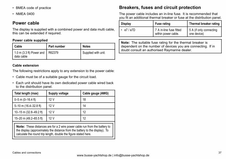
Power cableThe display is supplied with a combined power and data multi cable,this can be extended if required.
Power cable supplied
Cable Part number Notes
1.0 m (3.3 ft) Power anddata cable
R62379 Supplied with unit.
Cable extensionThe following restrictions apply to any extension to the power cable:
• Cable must be of a suitable gauge for the circuit load.
• Each unit should have its own dedicated power cable wired backto the distribution panel.
Total length (max) Supply voltage Cable gauge (AWG)
0–5 m (0–16.4 ft) 12 V 18
5–10 m (16.4–32.8 ft) 12 V 14
10–15 m (32.8–49.2 ft) 12 V 12
15–20 m (49.2–65.5 ft) 12 V 12
Note: These distances are for a 2 wire power cable run from the battery tothe display (approximately the distance from the battery to the display). Tocalculate the round trip length, double the figure stated here.
Breakers, fuses and circuit protectionThe power cable includes an in-line fuse. It is recommended thatyou fit an additional thermal breaker or fuse at the distribution panel.
Display Fuse rating Thermal breaker rating
• e7 / e7D 7 A in-line fuse fittedwithin power cable.
5 A (if only connectingone device)
Note: The suitable fuse rating for the thermal breaker isdependent on the number of devices you are connecting. If indoubt consult an authorised Raymarine dealer.
Cables and connections 37www.busse-yachtshop.de | [email protected]
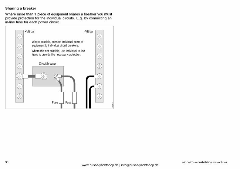
Sharing a breakerWhere more than 1 piece of equipment shares a breaker you mustprovide protection for the individual circuits. E.g. by connecting anin-line fuse for each power circuit.
D11
637-
1
+VE bar
Circuit breaker
FuseFuse
-VE bar
Where possible, connect individual items of equipment to individual circuit breakers.
Where this not possible, use individual in-line fuses to provide the necessary protection.
38 e7 / e7D — Installation instructionswww.busse-yachtshop.de | [email protected]
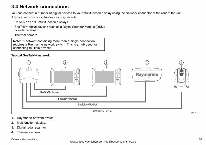
3.4 Network connectionsYou can connect a number of digital devices to your multifunction display using the Network connector at the rear of the unit.A typical network of digital devices may include:• Up to 6 e7 / e7D multifunction displays.• SeaTalkhs digital devices such as a Digital Sounder Module (DSM)or radar scanner.
• Thermal camera.
Note: A network containing more than a single connectionrequires a Raymarine network switch. This is a hub used forconnecting multiple devices.
Typical SeaTalkhs network
D12146-1
21 2 3 4
SeaTalkhs / RayNet
SeaTalkhs / RayNet
SeaTalkhs / RayNet
SeaTalkhs / RayNet
1. Raymarine network switch.2. Multifunction display.3. Digital radar scanner.4. Thermal camera.
Cables and connections 39www.busse-yachtshop.de | [email protected]
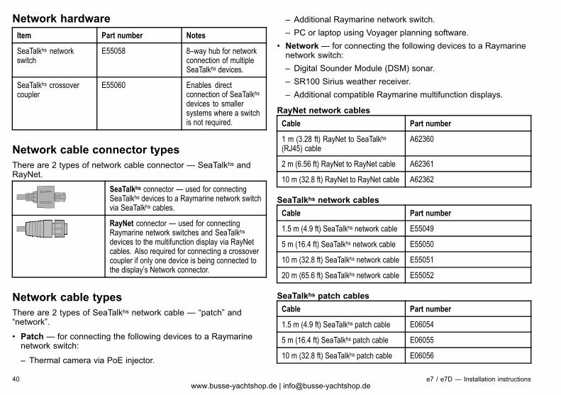
Network hardwareItem Part number Notes
SeaTalkhs networkswitch
E55058 8–way hub for networkconnection of multipleSeaTalkhs devices.
SeaTalkhs crossovercoupler
E55060 Enables directconnection of SeaTalkhsdevices to smallersystems where a switchis not required.
Network cable connector typesThere are 2 types of network cable connector — SeaTalkhs andRayNet.
SeaTalkhs connector — used for connectingSeaTalkhs devices to a Raymarine network switchvia SeaTalkhs cables.
RayNet connector — used for connectingRaymarine network switches and SeaTalkhsdevices to the multifunction display via RayNetcables. Also required for connecting a crossovercoupler if only one device is being connected tothe display’s Network connector.
Network cable typesThere are 2 types of SeaTalkhs network cable — “patch” and“network”.
• Patch — for connecting the following devices to a Raymarinenetwork switch:
– Thermal camera via PoE injector.
– Additional Raymarine network switch.– PC or laptop using Voyager planning software.
• Network— for connecting the following devices to a Raymarinenetwork switch:– Digital Sounder Module (DSM) sonar.– SR100 Sirius weather receiver.– Additional compatible Raymarine multifunction displays.
RayNet network cablesCable Part number
1 m (3.28 ft) RayNet to SeaTalkhs(RJ45) cable
A62360
2 m (6.56 ft) RayNet to RayNet cable A62361
10 m (32.8 ft) RayNet to RayNet cable A62362
SeaTalkhs network cablesCable Part number
1.5 m (4.9 ft) SeaTalkhs network cable E55049
5 m (16.4 ft) SeaTalkhs network cable E55050
10 m (32.8 ft) SeaTalkhs network cable E55051
20 m (65.6 ft) SeaTalkhs network cable E55052
SeaTalkhs patch cablesCable Part number
1.5 m (4.9 ft) SeaTalkhs patch cable E06054
5 m (16.4 ft) SeaTalkhs patch cable E06055
10 m (32.8 ft) SeaTalkhs patch cable E06056
40 e7 / e7D — Installation instructionswww.busse-yachtshop.de | [email protected]
Cable Part number
15 m (49.2 ft) SeaTalkhs patch cable A62136
20 m (65.6 ft) SeaTalkhs patch cable E06057
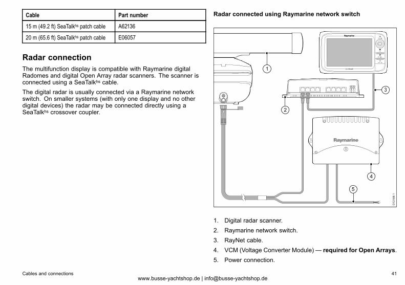
Radar connectionThe multifunction display is compatible with Raymarine digitalRadomes and digital Open Array radar scanners. The scanner isconnected using a SeaTalkhs cable.The digital radar is usually connected via a Raymarine networkswitch. On smaller systems (with only one display and no otherdigital devices) the radar may be connected directly using aSeaTalkhs crossover coupler.
Radar connected using Raymarine network switch
D12
168-
1
1
2
4
5
3
1. Digital radar scanner.2. Raymarine network switch.3. RayNet cable.4. VCM (Voltage Converter Module) — required for Open Arrays.5. Power connection.
Cables and connections 41www.busse-yachtshop.de | [email protected]
Radar connected directly to the display
D12150-1
2
5
4
1
3
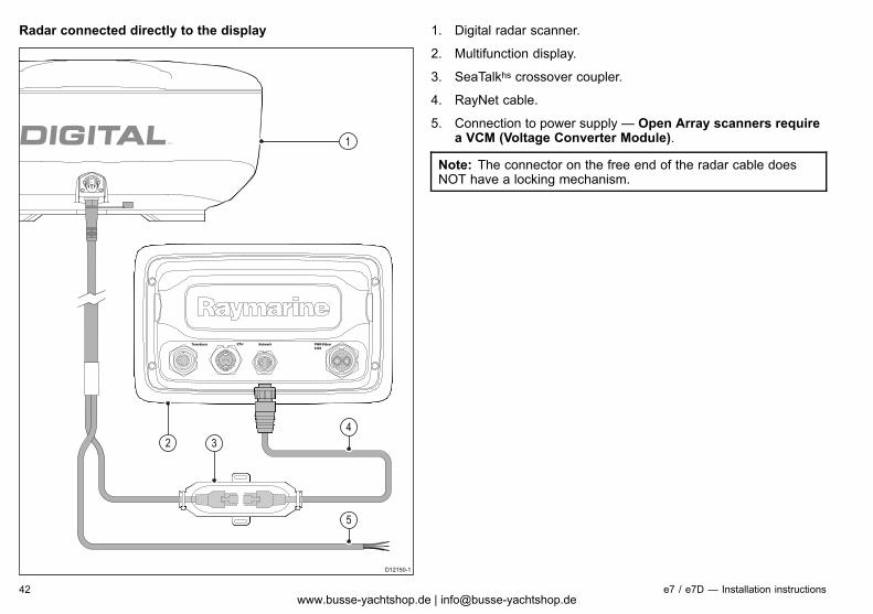
1. Digital radar scanner.
2. Multifunction display.
3. SeaTalkhs crossover coupler.
4. RayNet cable.
5. Connection to power supply — Open Array scanners requirea VCM (Voltage Converter Module).
Note: The connector on the free end of the radar cable doesNOT have a locking mechanism.
42 e7 / e7D — Installation instructionswww.busse-yachtshop.de | [email protected]
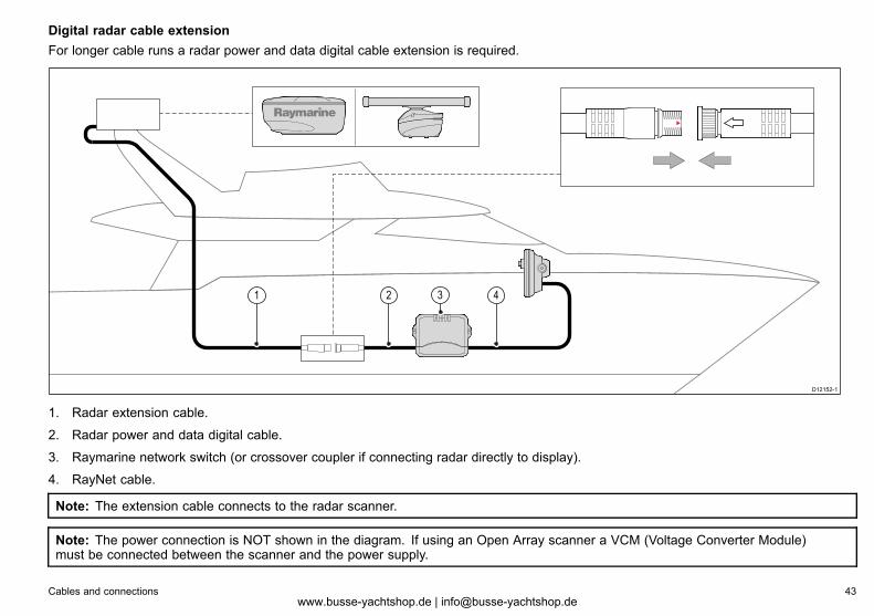
Digital radar cable extensionFor longer cable runs a radar power and data digital cable extension is required.
D12152-1
1 42 3
1. Radar extension cable.
2. Radar power and data digital cable.
3. Raymarine network switch (or crossover coupler if connecting radar directly to display).
4. RayNet cable.
Note: The extension cable connects to the radar scanner.
Note: The power connection is NOT shown in the diagram. If using an Open Array scanner a VCM (Voltage Converter Module)must be connected between the scanner and the power supply.
Cables and connections 43www.busse-yachtshop.de | [email protected]
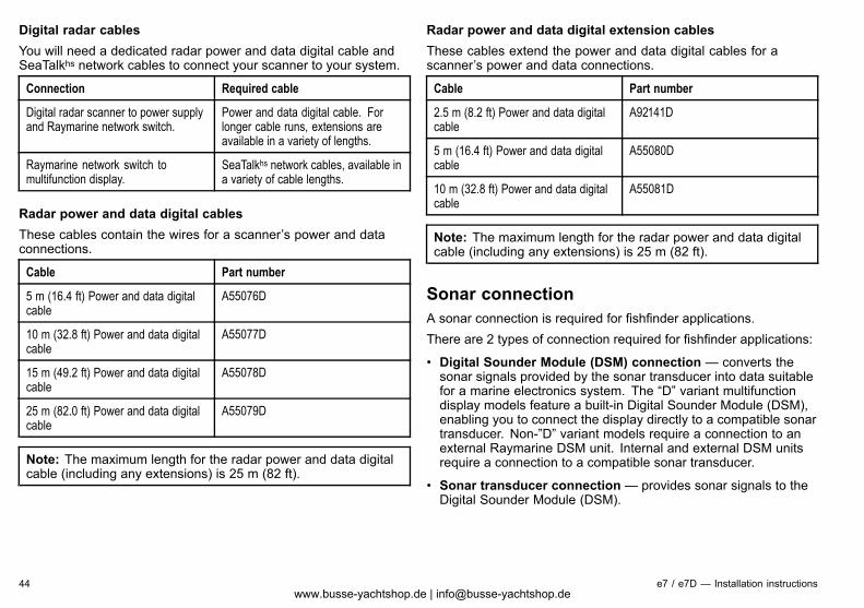
Digital radar cablesYou will need a dedicated radar power and data digital cable andSeaTalkhs network cables to connect your scanner to your system.
Connection Required cable
Digital radar scanner to power supplyand Raymarine network switch.
Power and data digital cable. Forlonger cable runs, extensions areavailable in a variety of lengths.
Raymarine network switch tomultifunction display.
SeaTalkhs network cables, available ina variety of cable lengths.
Radar power and data digital cablesThese cables contain the wires for a scanner’s power and dataconnections.
Cable Part number
5 m (16.4 ft) Power and data digitalcable
A55076D
10 m (32.8 ft) Power and data digitalcable
A55077D
15 m (49.2 ft) Power and data digitalcable
A55078D
25 m (82.0 ft) Power and data digitalcable
A55079D
Note: The maximum length for the radar power and data digitalcable (including any extensions) is 25 m (82 ft).
Radar power and data digital extension cablesThese cables extend the power and data digital cables for ascanner’s power and data connections.
Cable Part number
2.5 m (8.2 ft) Power and data digitalcable
A92141D
5 m (16.4 ft) Power and data digitalcable
A55080D
10 m (32.8 ft) Power and data digitalcable
A55081D
Note: The maximum length for the radar power and data digitalcable (including any extensions) is 25 m (82 ft).
Sonar connectionA sonar connection is required for fishfinder applications.There are 2 types of connection required for fishfinder applications:
• Digital Sounder Module (DSM) connection — converts thesonar signals provided by the sonar transducer into data suitablefor a marine electronics system. The “D” variant multifunctiondisplay models feature a built-in Digital Sounder Module (DSM),enabling you to connect the display directly to a compatible sonartransducer. Non-”D” variant models require a connection to anexternal Raymarine DSM unit. Internal and external DSM unitsrequire a connection to a compatible sonar transducer.
• Sonar transducer connection — provides sonar signals to theDigital Sounder Module (DSM).
44 e7 / e7D — Installation instructionswww.busse-yachtshop.de | [email protected]
Sonar DSM connection
D12157-1
1
2
3
4
SeaTalkhs / RayNet
SeaTalkhs / RayNet
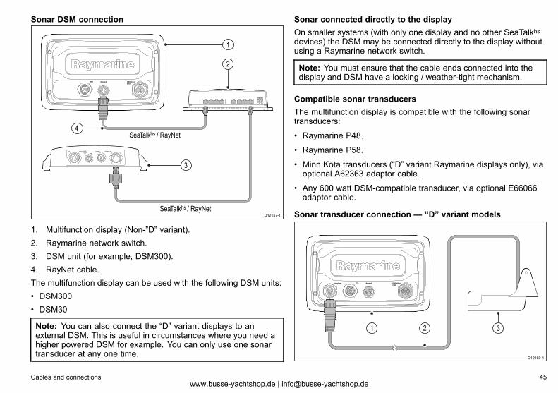
1. Multifunction display (Non-”D” variant).2. Raymarine network switch.3. DSM unit (for example, DSM300).4. RayNet cable.The multifunction display can be used with the following DSM units:• DSM300• DSM30
Note: You can also connect the “D” variant displays to anexternal DSM. This is useful in circumstances where you need ahigher powered DSM for example. You can only use one sonartransducer at any one time.
Sonar connected directly to the displayOn smaller systems (with only one display and no other SeaTalkhsdevices) the DSM may be connected directly to the display withoutusing a Raymarine network switch.
Note: You must ensure that the cable ends connected into thedisplay and DSM have a locking / weather-tight mechanism.
Compatible sonar transducersThe multifunction display is compatible with the following sonartransducers:
• Raymarine P48.
• Raymarine P58.
• Minn Kota transducers (“D” variant Raymarine displays only), viaoptional A62363 adaptor cable.
• Any 600 watt DSM-compatible transducer, via optional E66066adaptor cable.
Sonar transducer connection — “D” variant models
2
D12159-1
1 3
Cables and connections 45www.busse-yachtshop.de | [email protected]
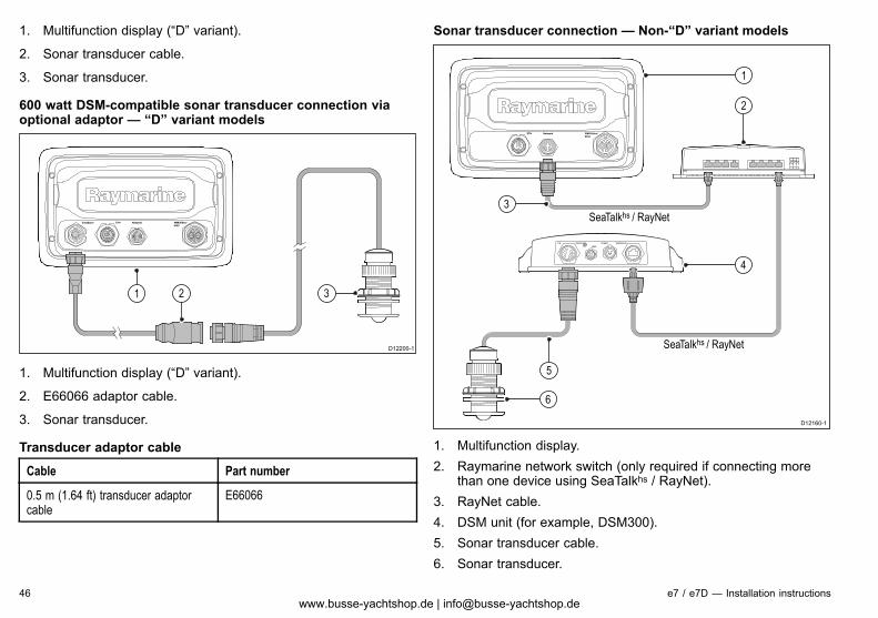
1. Multifunction display (“D” variant).
2. Sonar transducer cable.
3. Sonar transducer.
600 watt DSM-compatible sonar transducer connection viaoptional adaptor — “D” variant models
D12200-1
1 2 3
1. Multifunction display (“D” variant).
2. E66066 adaptor cable.
3. Sonar transducer.
Transducer adaptor cable
Cable Part number
0.5 m (1.64 ft) transducer adaptorcable
E66066
Sonar transducer connection — Non-“D” variant models
D12160-1
1
2
4
5
SeaTalkhs / RayNet
SeaTalkhs / RayNet
6
3
1. Multifunction display.2. Raymarine network switch (only required if connecting more
than one device using SeaTalkhs / RayNet).3. RayNet cable.4. DSM unit (for example, DSM300).5. Sonar transducer cable.6. Sonar transducer.
46 e7 / e7D — Installation instructionswww.busse-yachtshop.de | [email protected]
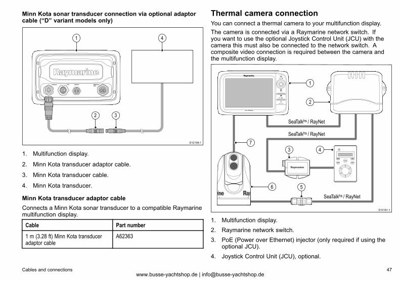
Minn Kota sonar transducer connection via optional adaptorcable (“D” variant models only)
D12158-1
1 4
2 3
1. Multifunction display.
2. Minn Kota transducer adaptor cable.
3. Minn Kota transducer cable.
4. Minn Kota transducer.
Minn Kota transducer adaptor cableConnects a Minn Kota sonar transducer to a compatible Raymarinemultifunction display.
Cable Part number
1 m (3.28 ft) Minn Kota transduceradaptor cable
A62363
Thermal camera connectionYou can connect a thermal camera to your multifunction display.The camera is connected via a Raymarine network switch. Ifyou want to use the optional Joystick Control Unit (JCU) with thecamera this must also be connected to the network switch. Acomposite video connection is required between the camera andthe multifunction display.
2
43
5
D12161-1
1
7
6
SeaTalkhs / RayNet
SeaTalkhs / RayNet
SeaTalkhs / RayNet
1. Multifunction display.2. Raymarine network switch.3. PoE (Power over Ethernet) injector (only required if using the
optional JCU).4. Joystick Control Unit (JCU), optional.
Cables and connections 47www.busse-yachtshop.de | [email protected]
5. Cable coupler.6. Thermal camera.7. Video connection.
Important notes• You can control the thermal camera using your multifunctionaldisplay. The Joystick Control Unit (JCU) is optional, but can beused in conjunction with the multifunctional display to control thethermal camera if required.
• “Dual payload” thermal cameras include 2 independent lenses; 1for thermal (infrared) and visible light, 1 for thermal (infrared) only.If you only have 1 display you should only connect the video cablelabelled “VIS / IR” (visible light / infrared) to the display. If you have2 or more displays you should connect 1 cable to each display.
• You can only view the thermal camera image on the multifunctiondisplay to which the camera is physically connected. If you wantto view the thermal camera image on more than 1 display youmust obtain a suitable third-party video distribution unit.
• For further information regarding the camera’s installation(including connections and mounting), refer to the installationinstructions that accompany the camera.
Thermal camera cablesCabling requirements for thermal cameras.
Camera to network switchA network patch cable is required to connect the camera to thenetwork switch. The connection is made between the cameracable tail and the network switch via the coupler (supplied with thecamera). Network patch cables are available in a variety of lengths.
Joystick Control Unit (JCU)An Ethernet (with power) cable is used to connect the JCU. The JCUis supplied with a 7.62 m (25 ft) Ethernet cable for this connection. Ifyou require a different length contact your dealer for suitable cables.
Power over Ethernet (PoE) injector to network switchA network patch cable is required for connecting the PoE injectorto the network switch. Network patch cables are available in avariety of lengths.
Video cablesContact your dealer for suitable cables and adaptors.
48 e7 / e7D — Installation instructionswww.busse-yachtshop.de | [email protected]
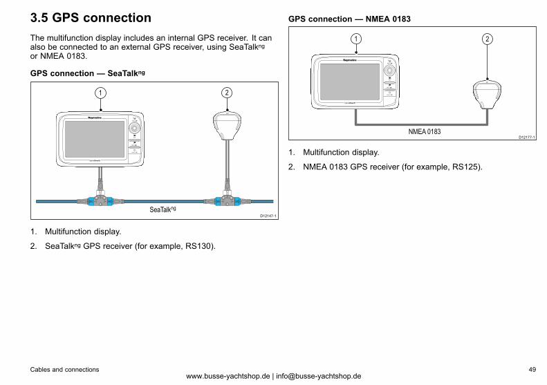
3.5 GPS connectionThe multifunction display includes an internal GPS receiver. It canalso be connected to an external GPS receiver, using SeaTalkngor NMEA 0183.
GPS connection — SeaTalkng
D12147-1SeaTalkng
21
1. Multifunction display.
2. SeaTalkng GPS receiver (for example, RS130).
GPS connection — NMEA 0183
D12177-1NMEA 0183
21
1. Multifunction display.
2. NMEA 0183 GPS receiver (for example, RS125).
Cables and connections 49www.busse-yachtshop.de | [email protected]
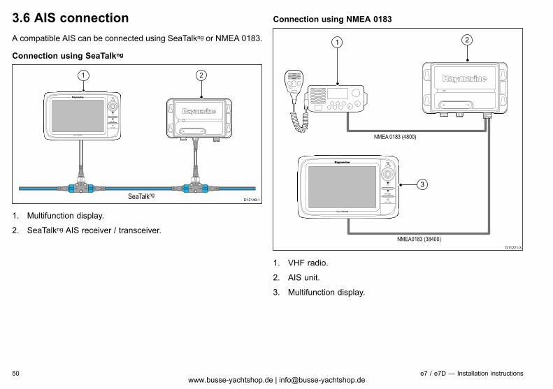
3.6 AIS connectionA compatible AIS can be connected using SeaTalkng or NMEA 0183.
Connection using SeaTalkng
D12149-1SeaTalkng
21
1. Multifunction display.
2. SeaTalkng AIS receiver / transceiver.
Connection using NMEA 0183
D11221-3
NMEA0183 (38400)
NMEA 0183 (4800)
3
1 2
1. VHF radio.
2. AIS unit.
3. Multifunction display.
50 e7 / e7D — Installation instructionswww.busse-yachtshop.de | [email protected]
3.7 Fastheading connectionIf you wish to use MARPA (radar target acquisition) functions onyour multifunction display you need either:
• An autopilot connected to the multifunction display via SeaTalkngor NMEA 0183. The compass is connected to the coursecomputer and calibrated via the pilot control head; or:
• A Raymarine or third-party fastheading sensor connected to themultifunction display via NMEA 0183.
Note: Please contact your dealer or Raymarine technical supportfor more information.
3.8 SeaTalkng connectionsThe display can connect to a SeaTalkng system.The display can use SeaTalkng to communicate with:
• SeaTalkng instruments (for example, i70).
• SeaTalkng autopilots (for example, p70 with SmartPilot SPXcourse computer).
• SeaTalk equipment via the optional SeaTalk to SeaTalkngconverter.
• NMEA 2000 equipment via optional DeviceNet adaptor cables.
Cables and connections 51www.busse-yachtshop.de | [email protected]
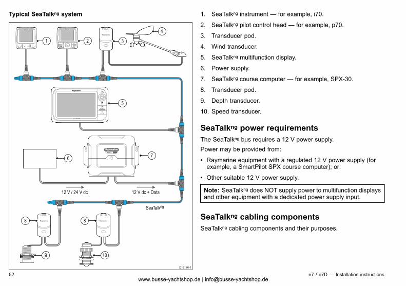
Typical SeaTalkng system
SMARTPILOT
D12176-1
12 V / 24 V dc 12 V dc + Data
SeaTalkng
1 2
6
9 10
8 8
5
7
3
4
1. SeaTalkng instrument — for example, i70.
2. SeaTalkng pilot control head — for example, p70.
3. Transducer pod.
4. Wind transducer.
5. SeaTalkng multifunction display.
6. Power supply.
7. SeaTalkng course computer — for example, SPX-30.
8. Transducer pod.
9. Depth transducer.
10. Speed transducer.
SeaTalkng power requirementsThe SeaTalkng bus requires a 12 V power supply.Power may be provided from:
• Raymarine equipment with a regulated 12 V power supply (forexample, a SmartPilot SPX course computer); or:
• Other suitable 12 V power supply.
Note: SeaTalkng does NOT supply power to multifunction displaysand other equipment with a dedicated power supply input.
SeaTalkng cabling componentsSeaTalkng cabling components and their purposes.
52 e7 / e7D — Installation instructionswww.busse-yachtshop.de | [email protected]
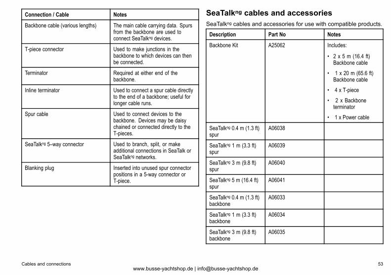
Connection / Cable Notes
Backbone cable (various lengths) The main cable carrying data. Spursfrom the backbone are used toconnect SeaTalkng devices.
T-piece connector Used to make junctions in thebackbone to which devices can thenbe connected.
Terminator Required at either end of thebackbone.
Inline terminator Used to connect a spur cable directlyto the end of a backbone; useful forlonger cable runs.
Spur cable Used to connect devices to thebackbone. Devices may be daisychained or connected directly to theT-pieces.
SeaTalkng 5–way connector Used to branch, split, or makeadditional connections in SeaTalk orSeaTalkng networks.
Blanking plug Inserted into unused spur connectorpositions in a 5-way connector orT-piece.
SeaTalkng cables and accessoriesSeaTalkng cables and accessories for use with compatible products.
Description Part No Notes
Backbone Kit A25062 Includes:
• 2 x 5 m (16.4 ft)Backbone cable
• 1 x 20 m (65.6 ft)Backbone cable
• 4 x T-piece
• 2 x Backboneterminator
• 1 x Power cable
SeaTalkng 0.4 m (1.3 ft)spur
A06038
SeaTalkng 1 m (3.3 ft)spur
A06039
SeaTalkng 3 m (9.8 ft)spur
A06040
SeaTalkng 5 m (16.4 ft)spur
A06041
SeaTalkng 0.4 m (1.3 ft)backbone
A06033
SeaTalkng 1 m (3.3 ft)backbone
A06034
SeaTalkng 3 m (9.8 ft)backbone
A06035
Cables and connections 53www.busse-yachtshop.de | [email protected]

Description Part No Notes
SeaTalkng 5 m (16.4 ft)backbone
A06036
SeaTalkng 9 m (29.5 ft)backbone
A06068
SeaTalkng 20 m (65.6 ft)backbone
A06037
SeaTalkng to bare ends1 m (3.3 ft) spur
A06043
SeaTalkng to bare ends3 m (9.8 ft) spur
A06044
SeaTalkng Power cable A06049
SeaTalkng Terminator A06031
SeaTalkng T-piece A06028 Provides 1 x spurconnection
SeaTalkng 5–wayconnector
A06064 Provides 3 x spurconnections
SeaTalk to SeaTalkngconverter
E22158 Allows the connectionof SeaTalk devices to aSeaTalkng system.
SeaTalkng Inlineterminator
A80001 Provides directconnection of a spurcable to the end of abackbone cable. NoT-piece required.
SeaTalkng Blanking plug A06032
Description Part No Notes
SeaTalk (3 pin) toSeaTalkng adaptor cable0.4 m (1.3 ft)
A06047
SeaTalk2 (5 pin) toSeaTalkng adaptor cable0.4 m (1.3 ft)
A06048
DeviceNet adaptor cable(Female)
A06045 Allows the connection ofNMEA 2000 devices toa SeaTalkng system.
DeviceNet adaptor cable(Male)
A06046 Allows the connection ofNMEA 2000 devices toa SeaTalkng system.
DeviceNet adaptor cable(Female) to bare ends.
E05026 Allows the connection ofNMEA 2000 devices toa SeaTalkng system.
DeviceNet adaptor cable(Male) to bare ends.
E52027 Allows the connection ofNMEA 2000 devices toa SeaTalkng system.
54 e7 / e7D — Installation instructionswww.busse-yachtshop.de | [email protected]
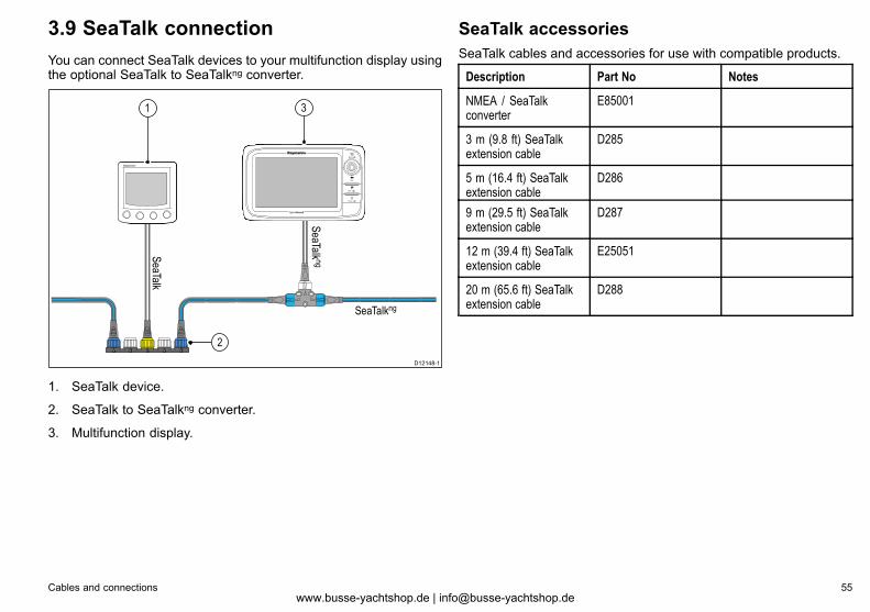
3.9 SeaTalk connectionYou can connect SeaTalk devices to your multifunction display usingthe optional SeaTalk to SeaTalkng converter.
D12148-1
SeaTalkng
SeaTalk
1
2
SeaTalk ng
3
1. SeaTalk device.
2. SeaTalk to SeaTalkng converter.
3. Multifunction display.
SeaTalk accessoriesSeaTalk cables and accessories for use with compatible products.
Description Part No Notes
NMEA / SeaTalkconverter
E85001
3 m (9.8 ft) SeaTalkextension cable
D285
5 m (16.4 ft) SeaTalkextension cable
D286
9 m (29.5 ft) SeaTalkextension cable
D287
12 m (39.4 ft) SeaTalkextension cable
E25051
20 m (65.6 ft) SeaTalkextension cable
D288
Cables and connections 55www.busse-yachtshop.de | [email protected]
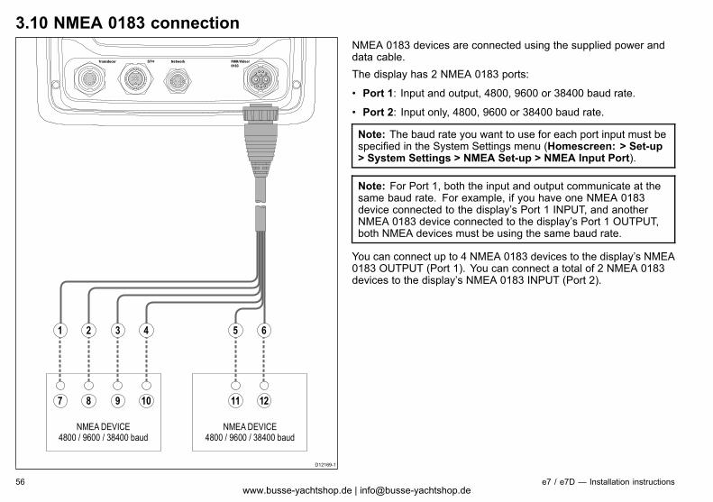
3.10 NMEA 0183 connection
6
D12169-1
1 2 3 4 5
117 8 9 10 12
NMEA DEVICE4800 / 9600 / 38400 baud
NMEA DEVICE4800 / 9600 / 38400 baud
NMEA 0183 devices are connected using the supplied power anddata cable.The display has 2 NMEA 0183 ports:
• Port 1: Input and output, 4800, 9600 or 38400 baud rate.
• Port 2: Input only, 4800, 9600 or 38400 baud rate.
Note: The baud rate you want to use for each port input must bespecified in the System Settings menu (Homescreen: > Set-up> System Settings > NMEA Set-up > NMEA Input Port).
Note: For Port 1, both the input and output communicate at thesame baud rate. For example, if you have one NMEA 0183device connected to the display’s Port 1 INPUT, and anotherNMEA 0183 device connected to the display’s Port 1 OUTPUT,both NMEA devices must be using the same baud rate.
You can connect up to 4 NMEA 0183 devices to the display’s NMEA0183 OUTPUT (Port 1). You can connect a total of 2 NMEA 0183devices to the display’s NMEA 0183 INPUT (Port 2).
56 e7 / e7D — Installation instructionswww.busse-yachtshop.de | [email protected]
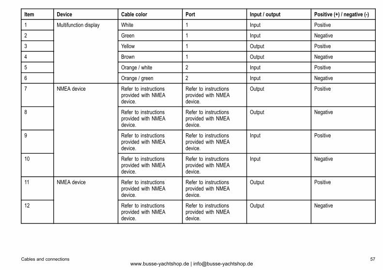
Item Device Cable color Port Input / output Positive (+) / negative (-)
1 White 1 Input Positive
2 Green 1 Input Negative
3 Yellow 1 Output Positive
4 Brown 1 Output Negative
5 Orange / white 2 Input Positive
6
Multifunction display
Orange / green 2 Input Negative
7 Refer to instructionsprovided with NMEAdevice.
Refer to instructionsprovided with NMEAdevice.
Output Positive
8 Refer to instructionsprovided with NMEAdevice.
Refer to instructionsprovided with NMEAdevice.
Output Negative
9 Refer to instructionsprovided with NMEAdevice.
Refer to instructionsprovided with NMEAdevice.
Input Positive
10
NMEA device
Refer to instructionsprovided with NMEAdevice.
Refer to instructionsprovided with NMEAdevice.
Input Negative
11 Refer to instructionsprovided with NMEAdevice.
Refer to instructionsprovided with NMEAdevice.
Output Positive
12
NMEA device
Refer to instructionsprovided with NMEAdevice.
Refer to instructionsprovided with NMEAdevice.
Output Negative
Cables and connections 57www.busse-yachtshop.de | [email protected]
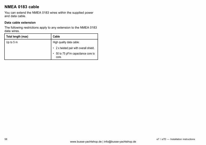
NMEA 0183 cableYou can extend the NMEA 0183 wires within the supplied powerand data cable.
Data cable extensionThe following restrictions apply to any extension to the NMEA 0183data wires.
Total length (max) Cable
Up to 5 m High quality data cable:
• 2 x twisted pair with overall shield.
• 50 to 75 pF/m capacitance core tocore.
58 e7 / e7D — Installation instructionswww.busse-yachtshop.de | [email protected]
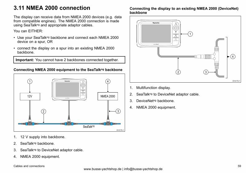
3.11 NMEA 2000 connectionThe display can receive data from NMEA 2000 devices (e.g. datafrom compatible engines). The NMEA 2000 connection is madeusing SeaTalkng and appropriate adaptor cables.You can EITHER:
• Use your SeaTalkng backbone and connect each NMEA 2000device on a spur, OR
• connect the display on a spur into an existing NMEA 2000backbone.
Important: You cannot have 2 backbones connected together.
Connecting NMEA 2000 equipment to the SeaTalkng backbone
NMEA 200012V
D12174-1
1
2
4
3
SeaTalkng
1. 12 V supply into backbone.
2. SeaTalkng backbone.
3. SeaTalkng to DeviceNet adaptor cable.
4. NMEA 2000 equipment.
Connecting the display to an existing NMEA 2000 (DeviceNet)backbone
D12175-1
32
4
1
1. Multifunction display.
2. SeaTalkng to DeviceNet adaptor cable.
3. DeviceNetng backbone.
4. NMEA 2000 equipment.
Cables and connections 59www.busse-yachtshop.de | [email protected]
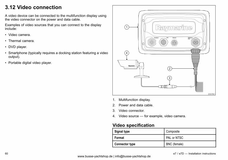
3.12 Video connectionA video device can be connected to the multifunction display usingthe video connector on the power and data cable.Examples of video sources that you can connect to the displayinclude:
• Video camera.
• Thermal camera.
• DVD player.
• Smartphone (typically requires a docking station featuring a videooutput).
• Portable digital video player.
D12178-1
1
2
4
3
1. Multifunction display.2. Power and data cable.3. Video connector.4. Video source — for example, video camera.
Video specificationSignal type Composite
Format PAL or NTSC
Connector type BNC (female)
60 e7 / e7D — Installation instructionswww.busse-yachtshop.de | [email protected]
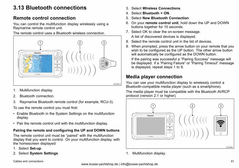
3.13 Bluetooth connections
Remote control connectionYou can control the multifunction display wirelessly using aRaymarine remote control unit.The remote control uses a Bluetooth wireless connection.
D12163-1
1 32
1. Multifunction display.2. Bluetooth connection.3. Raymarine Bluetooth remote control (for example, RCU-3).To use the remote control you must first:• Enable Bluetooth in the System Settings on the multifunctiondisplay.
• Pair the remote control unit with the multifunction display.
Pairing the remote and configuring the UP and DOWN buttonsThe remote control unit must be “paired” with the multifunctiondisplay that you want to control. On your multifunction display, withthe homescreen displayed:1. Select Set-up.2. Select System Settings.
3. Select Wireless Connections.4. Select Bluetooth > ON.5. Select New Bluetooth Connection.6. On your remote control unit, hold down the UP and DOWN
buttons together for 10 seconds.7. Select OK to clear the on-screen message.
A list of discovered devices is displayed.8. Select the remote control unit in the list of devices.9. When prompted, press the arrow button on your remote that you
wish to be configured as the UP button. The other arrow buttonwill automatically be configured as the DOWN button.If the pairing was successful a “Pairing Success” message willbe displayed. If a “Pairing Failure” or “Pairing Timeout” messageis displayed, repeat steps 1 to 9.
Media player connectionYou can use your multifunction display to wirelessly control aBluetooth-compatible media player (such as a smartphone).The media player must be compatible with the Bluetooth AVRCPprotocol (version 2.1 or higher).
D12164-1
1 32
1. Multifunction display.
Cables and connections 61www.busse-yachtshop.de | [email protected]
2. Bluetooth connection.
3. Bluetooth-compatible media player.
To use this feature you must first:
• Enable Bluetooth in the System Settings on the multifunctiondisplay.
• Enable Bluetooth on the media player device.
• Pair the media player device with the multifunction display.
• Enable Audio Control in the System Settings on the multifunctiondisplay.
Note: If your media player does not include built-in speakers itmay be necessary to connect the media player’s audio outputto an external audio system or a pair of headphones. For moreinformation refer to the instructions that accompany the mediaplayer device.
3.14 WiFi connections
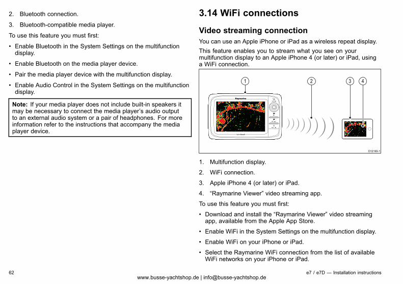
Video streaming connectionYou can use an Apple iPhone or iPad as a wireless repeat display.This feature enables you to stream what you see on yourmultifunction display to an Apple iPhone 4 (or later) or iPad, usinga WiFi connection.
D12165-1
3 421
1. Multifunction display.
2. WiFi connection.
3. Apple iPhone 4 (or later) or iPad.
4. “Raymarine Viewer” video streaming app.
To use this feature you must first:
• Download and install the “Raymarine Viewer” video streamingapp, available from the Apple App Store.
• Enable WiFi in the System Settings on the multifunction display.
• Enable WiFi on your iPhone or iPad.
• Select the Raymarine WiFi connection from the list of availableWiFi networks on your iPhone or iPad.
62 e7 / e7D — Installation instructionswww.busse-yachtshop.de | [email protected]
• Enable Device Streaming in the System Settings on themultifunction display.
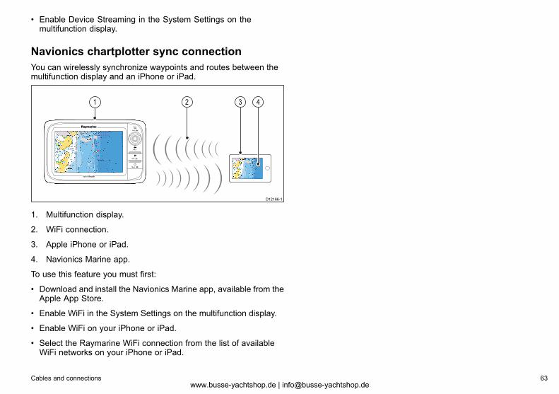
Navionics chartplotter sync connectionYou can wirelessly synchronize waypoints and routes between themultifunction display and an iPhone or iPad.
D12166-1
1 3 42
1. Multifunction display.
2. WiFi connection.
3. Apple iPhone or iPad.
4. Navionics Marine app.
To use this feature you must first:
• Download and install the Navionics Marine app, available from theApple App Store.
• Enable WiFi in the System Settings on the multifunction display.
• Enable WiFi on your iPhone or iPad.
• Select the Raymarine WiFi connection from the list of availableWiFi networks on your iPhone or iPad.
Cables and connections 63www.busse-yachtshop.de | [email protected]

64 e7 / e7D — Installation instructionswww.busse-yachtshop.de | [email protected]
Chapter 4: Location and mounting
Chapter contents• 4.1 Selecting a location on page 66
• 4.2 Removing the rear bezel on page 68
• 4.3 Flush mounting on page 69
• 4.4 Attaching the rear bezel on page 70
• 4.5 Bracket (trunnion) mounting on page 70
• 4.6 Front bezel on page 72
Location and mounting 65www.busse-yachtshop.de | [email protected]
4.1 Selecting a locationWarning: Potential ignition sourceThis product is NOT approved for use inhazardous/flammable atmospheres. Do NOT install ina hazardous/flammable atmosphere (such as in anengine room or near fuel tanks).
General location requirementsWhen selecting a location for your display it is important to considera number of factors.Key factors which can affect product performance are:• VentilationTo ensure adequate airflow:– Ensure that equipment is mounted in a compartment of suitablesize.
– Ensure that ventilation holes are not obstructed. Allowadequate separation of equipment.
Any specific requirements for each system component areprovided later in this chapter.
• Mounting surfaceEnsure equipment is adequately supported on a secure surface.Do not mount units or cut holes in places which may damage thestructure of the vessel.
• Cable entryEnsure the unit is mounted in a location which allows properrouting and connection of cables:– Minimum bend radius of 100 mm (3.94 in) unless otherwisestated.
– Use cable supports to prevent stress on connectors.• Water ingress
The display is suitable for mounting both above and below decks.It is waterproof to IPX6 standard. Although the unit is waterproof,it is good practice to locate it in a protected area away fromprolonged and direct exposure to rain and salt spray.
• Electrical interferenceSelect a location that is far enough away from devices thatmay cause interference, such as motors, generators and radiotransmitters / receivers.
• Power supplySelect a location that is as close as possible to the vessel’s DCpower source. This will help to keep cable runs to a minimum.
Compass safe distanceTo prevent potential interference with the vessel’s magneticcompasses, ensure an adequate distance is maintained from thedisplay.When choosing a suitable location for the multifunction display youshould aim to maintain the maximum possible distance betweenthe display and any compasses. Typically this distance shouldbe at least 1 m (3 ft) in all directions. However for some smallervessels it may not be possible to locate the display this far awayfrom a compass. In this situation, the following figures provide theminimum safe distance that should be maintained between thedisplay and any compasses.
66 e7 / e7D — Installation instructionswww.busse-yachtshop.de | [email protected]
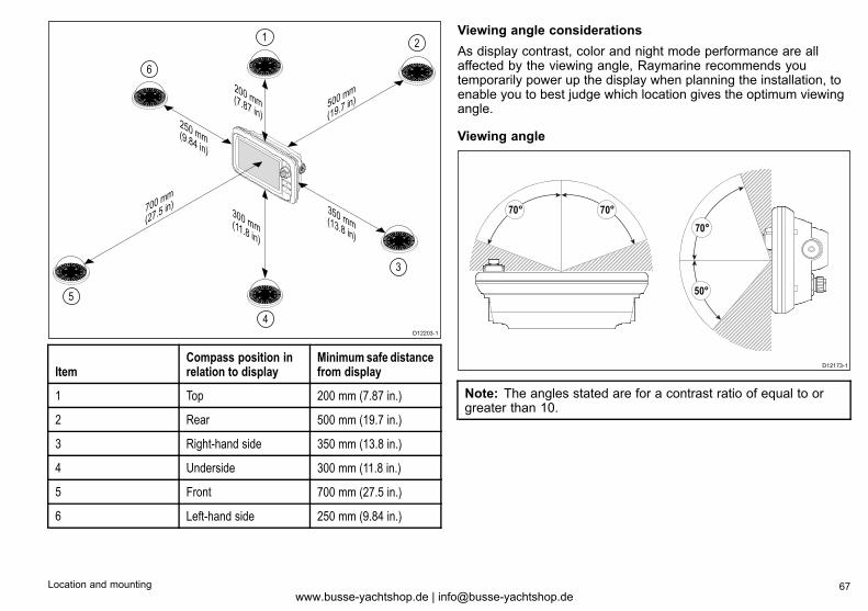
D12203-1
200 mm(7.87 in)
350 mm(13.8 in)
300 mm(11.8 in)
700 mm
(27.5 in)
500 mm
(19.7 in)
250 mm(9.84 in)
1 2
3
4
5
6
ItemCompass position inrelation to display
Minimum safe distancefrom display
1 Top 200 mm (7.87 in.)
2 Rear 500 mm (19.7 in.)
3 Right-hand side 350 mm (13.8 in.)
4 Underside 300 mm (11.8 in.)
5 Front 700 mm (27.5 in.)
6 Left-hand side 250 mm (9.84 in.)
Viewing angle considerationsAs display contrast, color and night mode performance are allaffected by the viewing angle, Raymarine recommends youtemporarily power up the display when planning the installation, toenable you to best judge which location gives the optimum viewingangle.
Viewing angle
������
������
������
����
����
����
����
����
D12173-1
50°
70°70°
70°
Note: The angles stated are for a contrast ratio of equal to orgreater than 10.
Location and mounting 67www.busse-yachtshop.de | [email protected]
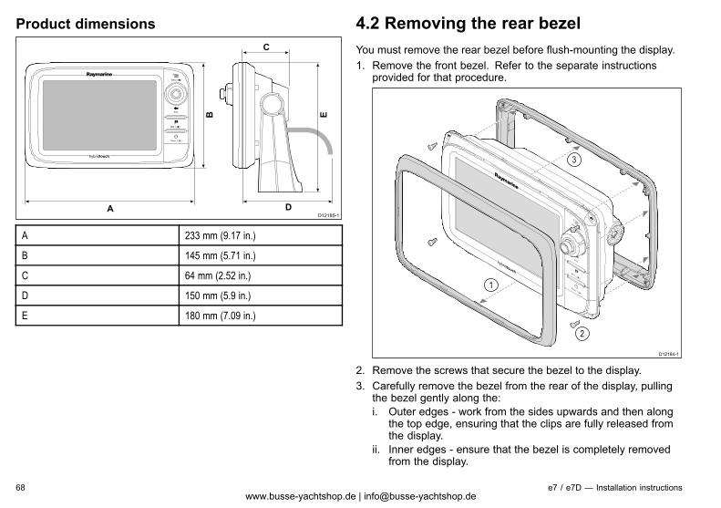
Product dimensions
A
C
DD12185-1
B E
A 233 mm (9.17 in.)
B 145 mm (5.71 in.)
C 64 mm (2.52 in.)
D 150 mm (5.9 in.)
E 180 mm (7.09 in.)
4.2 Removing the rear bezelYou must remove the rear bezel before flush-mounting the display.1. Remove the front bezel. Refer to the separate instructions
provided for that procedure.
D12184-1
2
3
1
2. Remove the screws that secure the bezel to the display.3. Carefully remove the bezel from the rear of the display, pulling
the bezel gently along the:i. Outer edges - work from the sides upwards and then along
the top edge, ensuring that the clips are fully released fromthe display.
ii. Inner edges - ensure that the bezel is completely removedfrom the display.
68 e7 / e7D — Installation instructionswww.busse-yachtshop.de | [email protected]
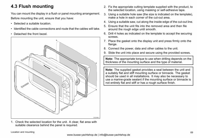
4.3 Flush mountingYou can mount the display in a flush or panel mounting arrangement.Before mounting the unit, ensure that you have:
• Selected a suitable location.
• Identified the cable connections and route that the cables will take.
• Detached the front bezel.
D12168-1
1. Check the selected location for the unit. A clear, flat area withsuitable clearance behind the panel is required.
2. Fix the appropriate cutting template supplied with the product, tothe selected location, using masking or self-adhesive tape.
3. Using a suitable hole saw (the size is indicated on the template),make a hole in each corner of the cut-out area.
4. Using a suitable saw, cut along the inside edge of the cut-out line.5. Ensure that the unit fits into the removed area and then file
around the rough edge until smooth.6. Drill 4 holes as indicated on the template to accept the securing
screws.7. Place the gasket onto the display unit and press firmly onto the
flange.8. Connect the power, data and other cables to the unit.9. Slide the unit into place and secure using the provided screws.
Note: The appropriate torque to use when drilling depends on thethickness of the mounting surface and the type of material.
Note: The supplied gasket provides a seal between the unit anda suitably flat and stiff mounting surface or binnacle. The gasketshould be used in all installations. It may also be necessary touse a marine-grade sealant if the mounting surface or binnacle isnot entirely flat and stiff or has a rough surface finish.
Location and mounting 69www.busse-yachtshop.de | [email protected]
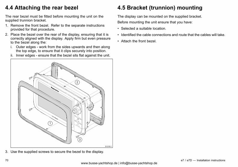
4.4 Attaching the rear bezelThe rear bezel must be fitted before mounting the unit on thesupplied trunnion bracket.1. Remove the front bezel. Refer to the separate instructions
provided for that procedure.2. Place the bezel over the rear of the display, ensuring that it is
correctly aligned with the display. Apply firm but even pressureto the bezel along the:i. Outer edges - work from the sides upwards and then along
the top edge, to ensure that it clips securely into position.ii. Inner edges - ensure that the bezel sits flat against the unit.
D12183-1
3
2
1
3. Use the supplied screws to secure the bezel to the display.
4.5 Bracket (trunnion) mountingThe display can be mounted on the supplied bracket.Before mounting the unit ensure that you have:
• Selected a suitable location.
• Identified the cable connections and route that the cables will take.
• Attach the front bezel.
70 e7 / e7D — Installation instructionswww.busse-yachtshop.de | [email protected]
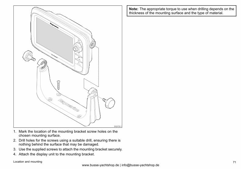
D12172-1
1. Mark the location of the mounting bracket screw holes on thechosen mounting surface.
2. Drill holes for the screws using a suitable drill, ensuring there isnothing behind the surface that may be damaged.
3. Use the supplied screws to attach the mounting bracket securely.4. Attach the display unit to the mounting bracket.
Note: The appropriate torque to use when drilling depends on thethickness of the mounting surface and the type of material.
Location and mounting 71www.busse-yachtshop.de | [email protected]
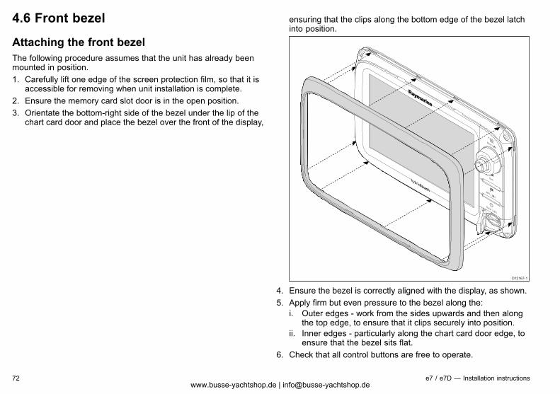
4.6 Front bezel
Attaching the front bezelThe following procedure assumes that the unit has already beenmounted in position.1. Carefully lift one edge of the screen protection film, so that it is
accessible for removing when unit installation is complete.2. Ensure the memory card slot door is in the open position.3. Orientate the bottom-right side of the bezel under the lip of the
chart card door and place the bezel over the front of the display,
ensuring that the clips along the bottom edge of the bezel latchinto position.
D12167-1
4. Ensure the bezel is correctly aligned with the display, as shown.5. Apply firm but even pressure to the bezel along the:
i. Outer edges - work from the sides upwards and then alongthe top edge, to ensure that it clips securely into position.
ii. Inner edges - particularly along the chart card door edge, toensure that the bezel sits flat.
6. Check that all control buttons are free to operate.
72 e7 / e7D — Installation instructionswww.busse-yachtshop.de | [email protected]
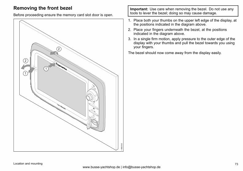
Removing the front bezelBefore proceeding ensure the memory card slot door is open.
1
1
2
2
D12189-1
Important: Use care when removing the bezel. Do not use anytools to lever the bezel; doing so may cause damage.
1. Place both your thumbs on the upper left edge of the display, atthe positions indicated in the diagram above.
2. Place your fingers underneath the bezel, at the positionsindicated in the diagram above.
3. In a single firm motion, apply pressure to the outer edge of thedisplay with your thumbs and pull the bezel towards you usingyour fingers.
The bezel should now come away from the display easily.
Location and mounting 73www.busse-yachtshop.de | [email protected]

74 e7 / e7D — Installation instructionswww.busse-yachtshop.de | [email protected]
Chapter 5: System checks
Chapter contents• 5.1 Initial power on test on page 76
• 5.2 Designating the data master on page 78
• 5.3 GPS check on page 78
• 5.4 Radar check on page 81
• 5.5 Sonar check on page 83
• 5.6 Thermal camera setup and checks on page 84
• 5.7 Enabling autopilot functions on page 86
• 5.8 Enabling AIS functions on page 86
• 5.9 Language selection on page 87
System checks 75www.busse-yachtshop.de | [email protected]
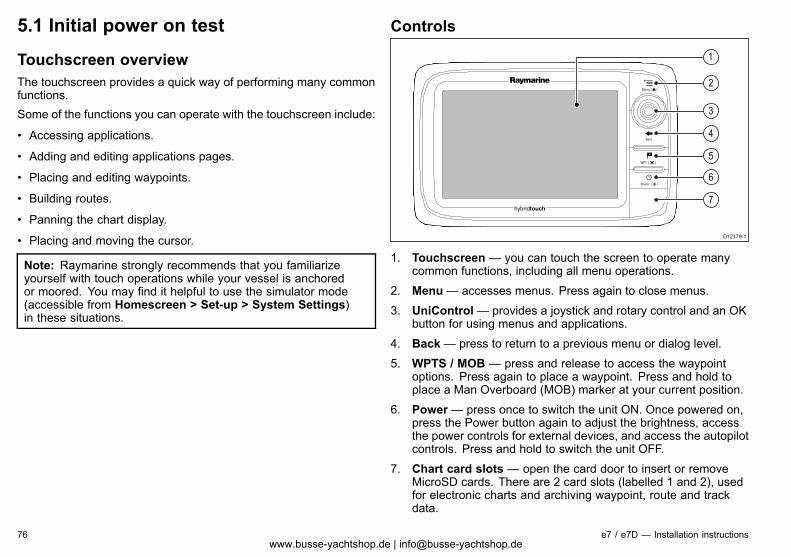
5.1 Initial power on test
Touchscreen overviewThe touchscreen provides a quick way of performing many commonfunctions.Some of the functions you can operate with the touchscreen include:
• Accessing applications.
• Adding and editing applications pages.
• Placing and editing waypoints.
• Building routes.
• Panning the chart display.
• Placing and moving the cursor.
Note: Raymarine strongly recommends that you familiarizeyourself with touch operations while your vessel is anchoredor moored. You may find it helpful to use the simulator mode(accessible from Homescreen > Set-up > System Settings)in these situations.
Controls
D12179-1
2
4
5
6
7
3
1
1. Touchscreen — you can touch the screen to operate manycommon functions, including all menu operations.
2. Menu— accesses menus. Press again to close menus.
3. UniControl— provides a joystick and rotary control and an OKbutton for using menus and applications.
4. Back— press to return to a previous menu or dialog level.
5. WPTS / MOB — press and release to access the waypointoptions. Press again to place a waypoint. Press and hold toplace a Man Overboard (MOB) marker at your current position.
6. Power— press once to switch the unit ON. Once powered on,press the Power button again to adjust the brightness, accessthe power controls for external devices, and access the autopilotcontrols. Press and hold to switch the unit OFF.
7. Chart card slots — open the card door to insert or removeMicroSD cards. There are 2 card slots (labelled 1 and 2), usedfor electronic charts and archiving waypoint, route and trackdata.
76 e7 / e7D — Installation instructionswww.busse-yachtshop.de | [email protected]
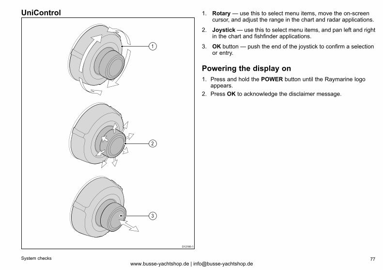
UniControl
D12180-1
1
2
3
1. Rotary — use this to select menu items, move the on-screencursor, and adjust the range in the chart and radar applications.
2. Joystick— use this to select menu items, and pan left and rightin the chart and fishfinder applications.
3. OK button — push the end of the joystick to confirm a selectionor entry.
Powering the display on1. Press and hold the POWER button until the Raymarine logo
appears.2. Press OK to acknowledge the disclaimer message.
System checks 77www.busse-yachtshop.de | [email protected]
5.2 Designating the data masterFor systems with 2 or more displays the following task must beperformed on the multifunction display that you want to designateas the data master.With the homescreen displayed:1. Select Set-up .2. Select Maintenance.3. Select Data Master.4. Select the display that you want to designate as the data master.5. Press the OK button.
5.3 GPS check
GPS selectionYou can use an internal or external GPS receiver.
• The multifunction display features an internal GPS receiver.
• You can also connect an external GPS receiver using SeaTalkngor NMEA 0183.
• Use the System Settings menu to enable or disable the internalGPS receiver.
Enabling or disabling the internal GPSWith the homescreen displayed:1. Select Set-Up.2. Select System Settings.3. Select Internal GPS.4. Select the On or Off option as appropriate.
Checking GPS operationYou can check that the GPS is functioning correctly using the chartapplication.1. Select the Chart page.
78 e7 / e7D — Installation instructionswww.busse-yachtshop.de | [email protected]
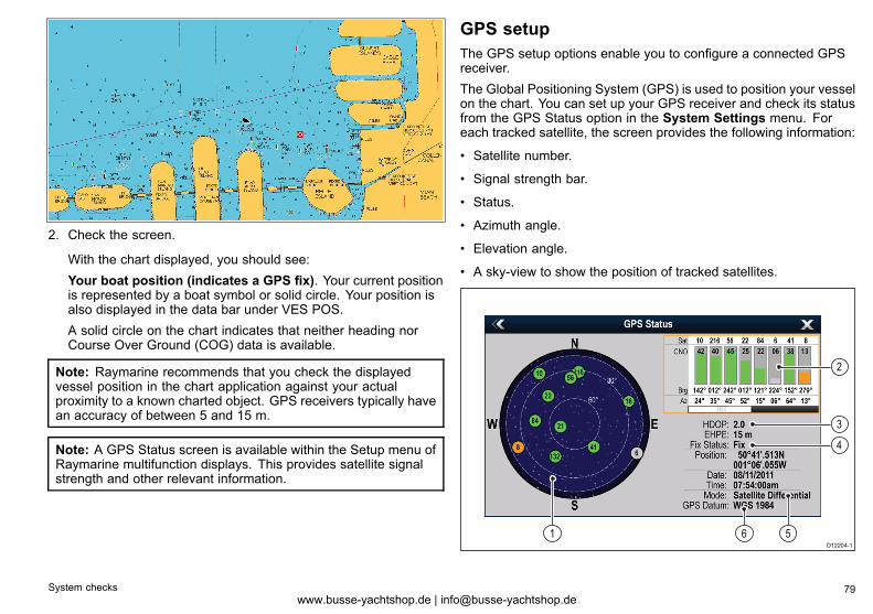
2. Check the screen.
With the chart displayed, you should see:Your boat position (indicates a GPS fix). Your current positionis represented by a boat symbol or solid circle. Your position isalso displayed in the data bar under VES POS.A solid circle on the chart indicates that neither heading norCourse Over Ground (COG) data is available.
Note: Raymarine recommends that you check the displayedvessel position in the chart application against your actualproximity to a known charted object. GPS receivers typically havean accuracy of between 5 and 15 m.
Note: A GPS Status screen is available within the Setup menu ofRaymarine multifunction displays. This provides satellite signalstrength and other relevant information.
GPS setupThe GPS setup options enable you to configure a connected GPSreceiver.The Global Positioning System (GPS) is used to position your vesselon the chart. You can set up your GPS receiver and check its statusfrom the GPS Status option in the System Settings menu. Foreach tracked satellite, the screen provides the following information:
• Satellite number.
• Signal strength bar.
• Status.
• Azimuth angle.
• Elevation angle.
• A sky-view to show the position of tracked satellites.
D12204-1
61
4
2
3
5
System checks 79www.busse-yachtshop.de | [email protected]
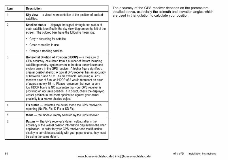
Item Description
1 Sky view — a visual representation of the position of trackedsatellites.
2 Satellite status — displays the signal strength and status ofeach satellite identified in the sky view diagram on the left of thescreen. The colored bars have the following meanings:
• Grey = searching for satellite.
• Green = satellite in use.
• Orange = tracking satellite.
3 Horizontal Dilution of Position (HDOP) — a measure ofGPS accuracy, calculated from a number of factors includingsatellite geometry, system errors in the data transmission andsystem errors in the GPS receiver. A higher figure signifies agreater positional error. A typical GPS receiver has an accuracyof between 5 and 15 m. As an example, assuming a GPSreceiver error of 5 m, an HDOP of 2 would represent an errorof approximately 15 m. Please remember that even a verylow HDOP figure is NO guarantee that your GPS receiver isproviding an accurate position. If in doubt, check the displayedvessel position in the chart application against your actualproximity to a known charted object.
4 Fix status — indicates the actual mode the GPS receiver isreporting (No Fix, Fix, D Fix or SD Fix).
5 Mode— the mode currently selected by the GPS receiver.
6 Datum — The GPS receiver’s datum setting affects theaccuracy of the vessel position information displayed in the chartapplication. In order for your GPS receiver and multifunctiondisplay to correlate accurately with your paper charts, they mustbe using the same datum.
The accuracy of the GPS receiver depends on the parametersdetailed above, especially the azimuth and elevation angles whichare used in triangulation to calculate your position.
80 e7 / e7D — Installation instructionswww.busse-yachtshop.de | [email protected]
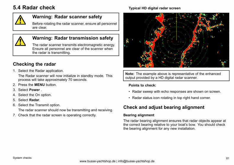
5.4 Radar checkWarning: Radar scanner safetyBefore rotating the radar scanner, ensure all personnelare clear.
Warning: Radar transmission safetyThe radar scanner transmits electromagnetic energy.Ensure all personnel are clear of the scanner whenthe radar is transmitting.
Checking the radar1. Select the Radar application.
The Radar scanner will now initialize in standby mode. Thisprocess will take approximately 70 seconds.
2. Press the MENU button.3. Select Power .4. Select the On option.5. Select Radar.6. Select the Transmit option.
The radar scanner should now be transmitting and receiving.7. Check that the radar screen is operating correctly.
Typical HD digital radar screen
Note: The example above is representative of the enhancedoutput provided by a HD digital radar scanner.
Points to check:
• Radar sweep with echo responses are shown on screen.
• Radar status icon rotating in top right hand corner.
Check and adjust bearing alignmentBearing alignmentThe radar bearing alignment ensures that radar objects appear atthe correct bearing relative to your boat’s bow. You should checkthe bearing alignment for any new installation.
System checks 81www.busse-yachtshop.de | [email protected]
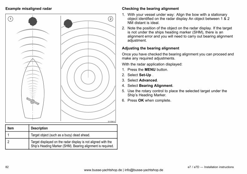
Example misaligned radar
D11590-2
1 2
Item Description
1 Target object (such as a buoy) dead ahead.
2 Target displayed on the radar display is not aligned with theShip’s Heading Marker (SHM). Bearing alignment is required.
Checking the bearing alignment1. With your vessel under way: Align the bow with a stationary
object identified on the radar display An object between 1 & 2NM distant is ideal.
2. Note the position of the object on the radar display. If the targetis not under the ships heading marker (SHM), there is analignment error and you will need to carry out bearing alignmentadjustment.
Adjusting the bearing alignmentOnce you have checked the bearing alignment you can proceed andmake any required adjustments.With the radar application displayed:1. Press the MENU button.2. Select Set-Up .3. Select Advanced.4. Select Bearing Alignment.5. Use the rotary control to place the selected target under the
Ship’s Heading Marker.6. Press OK when complete.
82 e7 / e7D — Installation instructionswww.busse-yachtshop.de | [email protected]
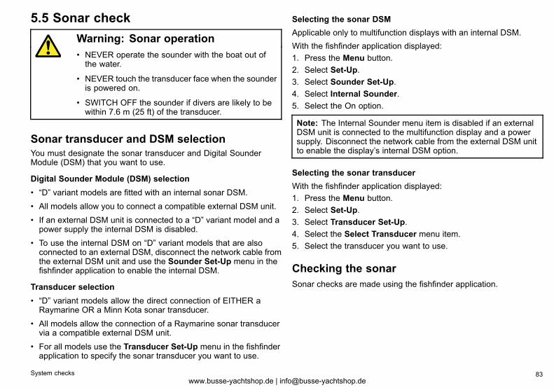
5.5 Sonar checkWarning: Sonar operation• NEVER operate the sounder with the boat out ofthe water.
• NEVER touch the transducer face when the sounderis powered on.
• SWITCH OFF the sounder if divers are likely to bewithin 7.6 m (25 ft) of the transducer.
Sonar transducer and DSM selectionYou must designate the sonar transducer and Digital SounderModule (DSM) that you want to use.
Digital Sounder Module (DSM) selection• “D” variant models are fitted with an internal sonar DSM.• All models allow you to connect a compatible external DSM unit.• If an external DSM unit is connected to a “D” variant model and apower supply the internal DSM is disabled.
• To use the internal DSM on “D” variant models that are alsoconnected to an external DSM, disconnect the network cable fromthe external DSM unit and use the Sounder Set-Up menu in thefishfinder application to enable the internal DSM.
Transducer selection• “D” variant models allow the direct connection of EITHER aRaymarine OR a Minn Kota sonar transducer.
• All models allow the connection of a Raymarine sonar transducervia a compatible external DSM unit.
• For all models use the Transducer Set-Up menu in the fishfinderapplication to specify the sonar transducer you want to use.
Selecting the sonar DSMApplicable only to multifunction displays with an internal DSM.With the fishfinder application displayed:1. Press the Menu button.2. Select Set-Up.3. Select Sounder Set-Up.4. Select Internal Sounder.5. Select the On option.
Note: The Internal Sounder menu item is disabled if an externalDSM unit is connected to the multifunction display and a powersupply. Disconnect the network cable from the external DSM unitto enable the display’s internal DSM option.
Selecting the sonar transducerWith the fishfinder application displayed:1. Press the Menu button.2. Select Set-Up.3. Select Transducer Set-Up.4. Select the Select Transducer menu item.5. Select the transducer you want to use.
Checking the sonarSonar checks are made using the fishfinder application.
System checks 83www.busse-yachtshop.de | [email protected]
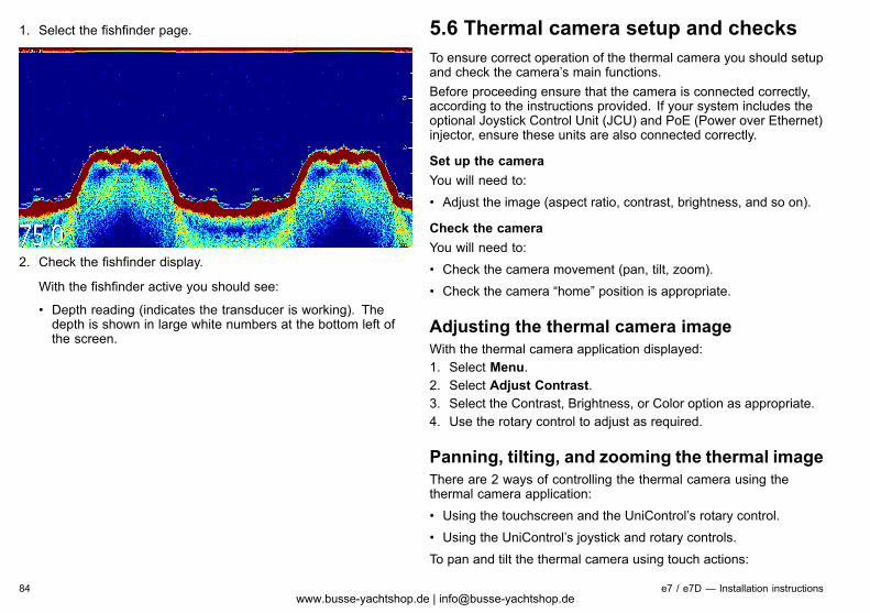
1. Select the fishfinder page.
2. Check the fishfinder display.
With the fishfinder active you should see:
• Depth reading (indicates the transducer is working). Thedepth is shown in large white numbers at the bottom left ofthe screen.
5.6 Thermal camera setup and checksTo ensure correct operation of the thermal camera you should setupand check the camera’s main functions.Before proceeding ensure that the camera is connected correctly,according to the instructions provided. If your system includes theoptional Joystick Control Unit (JCU) and PoE (Power over Ethernet)injector, ensure these units are also connected correctly.
Set up the cameraYou will need to:• Adjust the image (aspect ratio, contrast, brightness, and so on).
Check the cameraYou will need to:• Check the camera movement (pan, tilt, zoom).• Check the camera “home” position is appropriate.
Adjusting the thermal camera imageWith the thermal camera application displayed:1. Select Menu.2. Select Adjust Contrast.3. Select the Contrast, Brightness, or Color option as appropriate.4. Use the rotary control to adjust as required.
Panning, tilting, and zooming the thermal imageThere are 2 ways of controlling the thermal camera using thethermal camera application:• Using the touchscreen and the UniControl’s rotary control.• Using the UniControl’s joystick and rotary controls.To pan and tilt the thermal camera using touch actions:
84 e7 / e7D — Installation instructionswww.busse-yachtshop.de | [email protected]
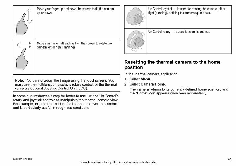
Move your finger up and down the screen to tilt the cameraup or down.
Move your finger left and right on the screen to rotate thecamera left or right (panning).
Note: You cannot zoom the image using the touchscreen. Youmust use the multifunction display’s rotary control, or the thermalcamera’s optional Joystick Control Unit (JCU).
In some circumstances it may be better to use just the UniControl’srotary and joystick controls to manipulate the thermal camera view.For example, this method is ideal for finer control over the cameraand is particularly useful in rough sea conditions.
UniControl joystick — is used for rotating the camera left orright (panning), or tilting the camera up or down.
UniControl rotary — is used to zoom in and out.
Resetting the thermal camera to the homepositionIn the thermal camera application:1. Select Menu.2. Select Camera Home.
The camera returns to its currently defined home position, andthe “Home” icon appears on-screen momentarily.
System checks 85www.busse-yachtshop.de | [email protected]
5.7 Enabling autopilot functionsWith the homescreen displayed:1. Select Set-up.2. Select System Settings.3. Select Autopilot Control.4. Select the On or Off option as appropriate.5. Use the Back button to return to the System Settings menu.6. Select Pilot Controls.
If this menu option is disabled, no autopilot has been found.Check the physical connections, then repeat steps 1 to 6.
7. The Pilot Control dialog is displayed, indicating that pilot controlis enabled and an autopilot is detected.
5.8 Enabling AIS functionsBefore proceeding ensure AIS unit is connected to NMEA Port 1.With the homescreen displayed:1. Select Set-Up.2. Select System Settings.3. Select NMEA Set-Up.4. Select NMEA Input Port 1.5. Select the AIS 38400 option.6. Use the Back button to return to the System Settings menu.7. Select External Devices.8. Select the AIS unit.
The Track Targets menu is displayed.9. Adjust the AIS options as appropriate.
86 e7 / e7D — Installation instructionswww.busse-yachtshop.de | [email protected]
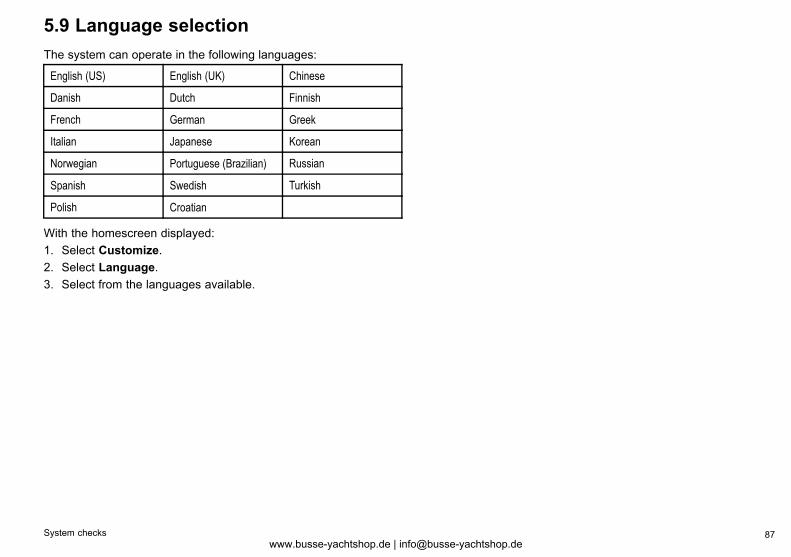
5.9 Language selectionThe system can operate in the following languages:
English (US) English (UK) Chinese
Danish Dutch Finnish
French German Greek
Italian Japanese Korean
Norwegian Portuguese (Brazilian) Russian
Spanish Swedish Turkish
Polish Croatian
With the homescreen displayed:1. Select Customize.2. Select Language.3. Select from the languages available.
System checks 87www.busse-yachtshop.de | [email protected]

88 e7 / e7D — Installation instructionswww.busse-yachtshop.de | [email protected]
Chapter 6: Troubleshooting
Chapter contents• 6.1 Troubleshooting on page 90
• 6.2 Power up troubleshooting on page 91
• 6.3 Radar troubleshooting on page 92
• 6.4 GPS troubleshooting on page 93
• 6.5 Sonar troubleshooting on page 94
• 6.6 Thermal camera troubleshooting on page 96
• 6.7 System data troubleshooting on page 99
• 6.8 Video troubleshooting on page 100
• 6.9 WiFi troubleshooting on page 101
• 6.10 Bluetooth troubleshooting on page 102
• 6.11 Touchscreen troubleshooting on page 103
• 6.12 Miscellaneous troubleshooting on page 104
Troubleshooting 89www.busse-yachtshop.de | [email protected]
6.1 TroubleshootingThe troubleshooting information provides possible causes andcorrective action required for common problems associated withmarine electronics installations.All Raymarine products are, prior to packing and shipping, subjectedto comprehensive test and quality assurance programs. However,if you experience problems with the operation of your product thissection will help you to diagnose and correct problems in order torestore normal operation.If after referring to this section you are still having problems with yourunit, please contact Raymarine Technical Support for further advice.
90 e7 / e7D — Installation instructionswww.busse-yachtshop.de | [email protected]
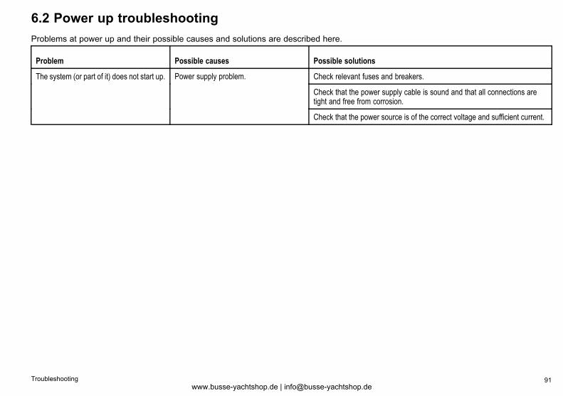
6.2 Power up troubleshootingProblems at power up and their possible causes and solutions are described here.
Problem Possible causes Possible solutions
Check relevant fuses and breakers.
Check that the power supply cable is sound and that all connections aretight and free from corrosion.
The system (or part of it) does not start up. Power supply problem.
Check that the power source is of the correct voltage and sufficient current.
Troubleshooting 91www.busse-yachtshop.de | [email protected]
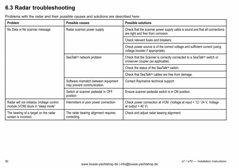
6.3 Radar troubleshootingProblems with the radar and their possible causes and solutions are described here.
Problem Possible causes Possible solutions
Check that the scanner power supply cable is sound and that all connectionsare tight and free from corrosion.
Check relevant fuses and breakers.
Radar scanner power supply
Check power source is of the correct voltage and sufficient current (usingvoltage booster if appropriate).
Check that the Scanner is correctly connected to a SeaTalkhs switch orcrossover coupler (as applicable).
Check the status of the SeaTalkhs switch.
SeaTalkhs network problem
Check that SeaTalkhs cables are free from damage.
Software mismatch between equipmentmay prevent communication.
Contact Raymarine technical support.
No Data or No scanner message
Switch at scanner pedestal in OFFposition
Ensure scanner pedestal switch is in ON position.
Radar will not initialize (Voltage controlmodule (VCM) stuck in “sleep mode”
Intermittent or poor power connection Check power connection at VCM. (Voltage at input = 12 / 24 V, Voltageat output = 40 V)
The bearing of a target on the radarscreen is incorrect.
The radar bearing alignment requirescorrecting.
Check and adjust radar bearing alignment.
92 e7 / e7D — Installation instructionswww.busse-yachtshop.de | [email protected]
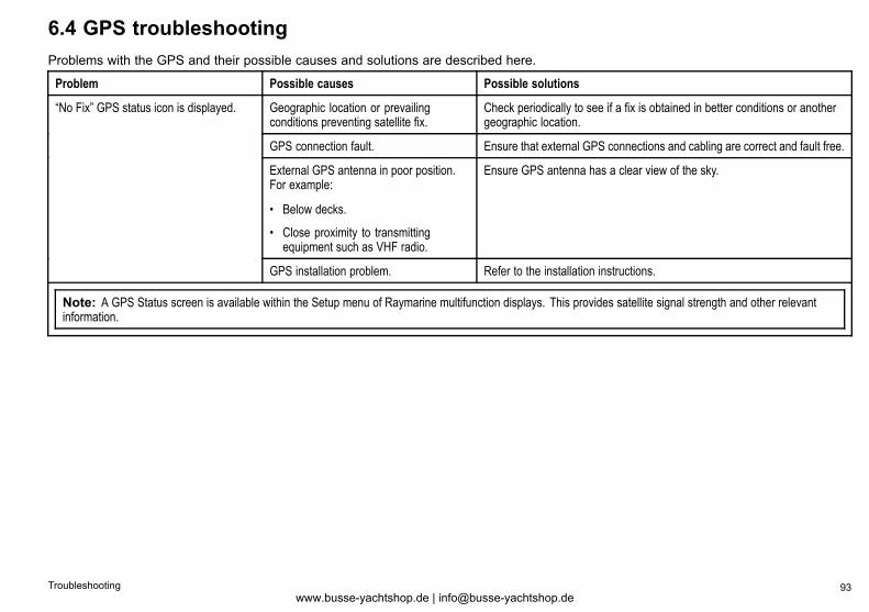
6.4 GPS troubleshootingProblems with the GPS and their possible causes and solutions are described here.
Problem Possible causes Possible solutions
Geographic location or prevailingconditions preventing satellite fix.
Check periodically to see if a fix is obtained in better conditions or anothergeographic location.
GPS connection fault. Ensure that external GPS connections and cabling are correct and fault free.
External GPS antenna in poor position.For example:
• Below decks.
• Close proximity to transmittingequipment such as VHF radio.
Ensure GPS antenna has a clear view of the sky.
“No Fix” GPS status icon is displayed.
GPS installation problem. Refer to the installation instructions.
Note: A GPS Status screen is available within the Setup menu of Raymarine multifunction displays. This provides satellite signal strength and other relevantinformation.
Troubleshooting 93www.busse-yachtshop.de | [email protected]
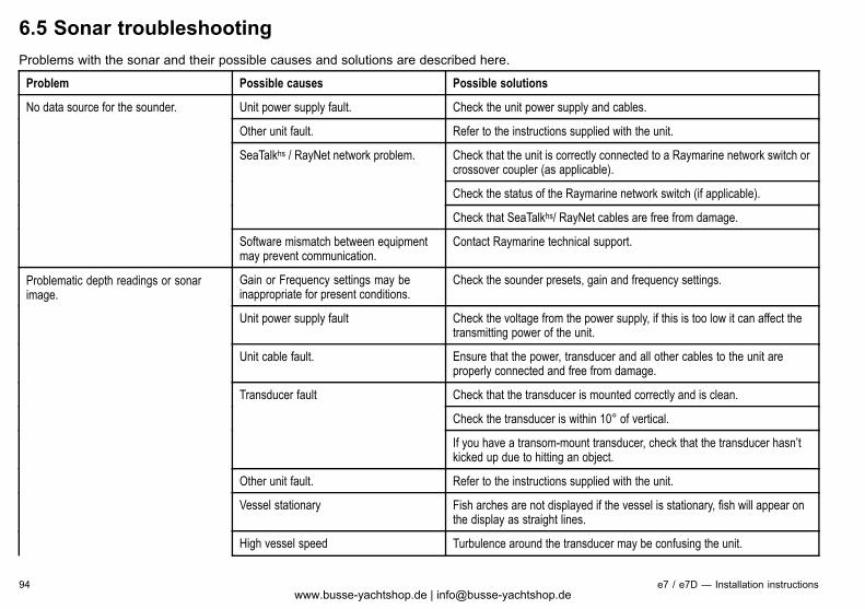
6.5 Sonar troubleshootingProblems with the sonar and their possible causes and solutions are described here.
Problem Possible causes Possible solutions
Unit power supply fault. Check the unit power supply and cables.
Other unit fault. Refer to the instructions supplied with the unit.
Check that the unit is correctly connected to a Raymarine network switch orcrossover coupler (as applicable).
Check the status of the Raymarine network switch (if applicable).
SeaTalkhs / RayNet network problem.
Check that SeaTalkhs/ RayNet cables are free from damage.
No data source for the sounder.
Software mismatch between equipmentmay prevent communication.
Contact Raymarine technical support.
Gain or Frequency settings may beinappropriate for present conditions.
Check the sounder presets, gain and frequency settings.
Unit power supply fault Check the voltage from the power supply, if this is too low it can affect thetransmitting power of the unit.
Unit cable fault. Ensure that the power, transducer and all other cables to the unit areproperly connected and free from damage.
Check that the transducer is mounted correctly and is clean.
Check the transducer is within 10° of vertical.
Transducer fault
If you have a transom-mount transducer, check that the transducer hasn’tkicked up due to hitting an object.
Other unit fault. Refer to the instructions supplied with the unit.
Vessel stationary Fish arches are not displayed if the vessel is stationary, fish will appear onthe display as straight lines.
High vessel speed Turbulence around the transducer may be confusing the unit.
Problematic depth readings or sonarimage.
94 e7 / e7D — Installation instructionswww.busse-yachtshop.de | [email protected]
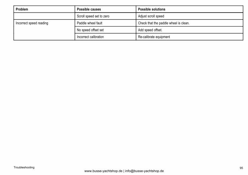
Problem Possible causes Possible solutions
Scroll speed set to zero Adjust scroll speed
Paddle wheel fault Check that the paddle wheel is clean.
No speed offset set Add speed offset.
Incorrect speed reading
Incorrect calibration Re-calibrate equipment
Troubleshooting 95www.busse-yachtshop.de | [email protected]
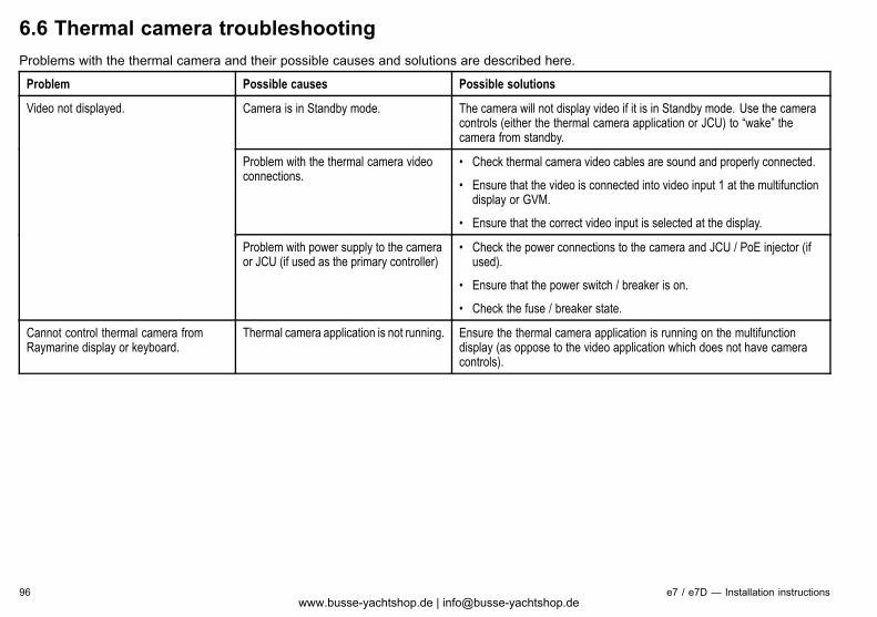
6.6 Thermal camera troubleshootingProblems with the thermal camera and their possible causes and solutions are described here.
Problem Possible causes Possible solutions
Camera is in Standby mode. The camera will not display video if it is in Standby mode. Use the cameracontrols (either the thermal camera application or JCU) to “wake” thecamera from standby.
Problem with the thermal camera videoconnections.
• Check thermal camera video cables are sound and properly connected.
• Ensure that the video is connected into video input 1 at the multifunctiondisplay or GVM.
• Ensure that the correct video input is selected at the display.
Video not displayed.
Problem with power supply to the cameraor JCU (if used as the primary controller)
• Check the power connections to the camera and JCU / PoE injector (ifused).
• Ensure that the power switch / breaker is on.
• Check the fuse / breaker state.
Cannot control thermal camera fromRaymarine display or keyboard.
Thermal camera application is not running. Ensure the thermal camera application is running on the multifunctiondisplay (as oppose to the video application which does not have cameracontrols).
96 e7 / e7D — Installation instructionswww.busse-yachtshop.de | [email protected]
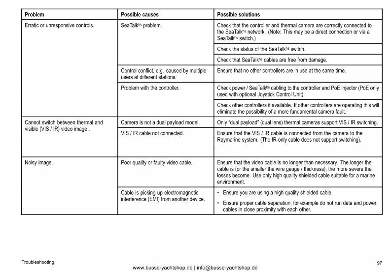
Problem Possible causes Possible solutions
Check that the controller and thermal camera are correctly connected tothe SeaTalkhs network. (Note: This may be a direct connection or via aSeaTalkhs switch.)
Check the status of the SeaTalkhs switch.
SeaTalkhs problem.
Check that SeaTalkhs cables are free from damage.
Control conflict, e.g. caused by multipleusers at different stations.
Ensure that no other controllers are in use at the same time.
Check power / SeaTalkhs cabling to the controller and PoE injector (PoE onlyused with optional Joystick Control Unit).
Erratic or unresponsive controls.
Problem with the controller.
Check other controllers if available. If other controllers are operating this willeliminate the possibility of a more fundamental camera fault.
Camera is not a dual payload model. Only “dual payload” (dual lens) thermal cameras support VIS / IR switching.Cannot switch between thermal andvisible (VIS / IR) video image .
VIS / IR cable not connected. Ensure that the VIS / IR cable is connected from the camera to theRaymarine system. (The IR-only cable does not support switching).
Poor quality or faulty video cable. Ensure that the video cable is no longer than necessary. The longer thecable is (or the smaller the wire gauge / thickness), the more severe thelosses become. Use only high quality shielded cable suitable for a marineenvironment.
Noisy image.
Cable is picking up electromagneticinterference (EMI) from another device.
• Ensure you are using a high quality shielded cable.
• Ensure proper cable separation, for example do not run data and powercables in close proximity with each other.
Troubleshooting 97www.busse-yachtshop.de | [email protected]
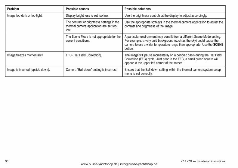
Problem Possible causes Possible solutions
Display brightness is set too low. Use the brightness controls at the display to adjust accordingly.
The contrast or brightness settings in thethermal camera application are set toolow.
Use the appropriate softkeys in the thermal camera application to adjust thecontrast and brightness of the image.
Image too dark or too light.
The Scene Mode is not appropriate for thecurrent conditions.
A particular environment may benefit from a different Scene Mode setting.For example, a very cold background (such as the sky) could cause thecamera to use a wider temperature range than appropriate. Use the SCENEbutton.
Image freezes momentarily. FFC (Flat Field Correction). The image will pause momentarily on a periodic basis during the Flat FieldCorrection (FFC) cycle. Just prior to the FFC, a small green square willappear in the upper left corner of the screen.
Image is inverted (upside down). Camera “Ball down” setting is incorrect. Ensure that the Ball down setting within the thermal camera system setupmenu is set correctly.
98 e7 / e7D — Installation instructionswww.busse-yachtshop.de | [email protected]
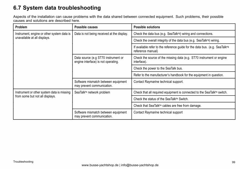
6.7 System data troubleshootingAspects of the installation can cause problems with the data shared between connected equipment. Such problems, their possiblecauses and solutions are described here.
Problem Possible causes Possible solutions
Check the data bus (e.g. SeaTalkng) wiring and connections.
Check the overall integrity of the data bus (e.g. SeaTalkng) wiring.
Data is not being received at the display.
If available refer to the reference guide for the data bus. (e.g. SeaTalkngreference manual)
Check the source of the missing data (e.g. ST70 instrument or engineinterface).
Check the power to the SeaTalk bus.
Data source (e.g ST70 instrument orengine interface) is not operating.
Refer to the manufacturer’s handbook for the equipment in question.
Instrument, engine or other system data isunavailable at all displays.
Software mismatch between equipmentmay prevent communication.
Contact Raymarine technical support.
Check that all required equipment is connected to the SeaTalkhs switch.
Check the status of the SeaTalkhs Switch.
SeaTalkhs network problem
Check that SeaTalkhs cables are free from damage.
Instrument or other system data is missingfrom some but not all displays.
Software mismatch between equipmentmay prevent communication.
Contact Raymarine technical support
Troubleshooting 99www.busse-yachtshop.de | [email protected]
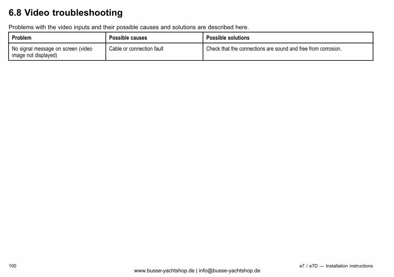
6.8 Video troubleshootingProblems with the video inputs and their possible causes and solutions are described here.
Problem Possible causes Possible solutions
No signal message on screen (videoimage not displayed)
Cable or connection fault Check that the connections are sound and free from corrosion.
100 e7 / e7D — Installation instructionswww.busse-yachtshop.de | [email protected]
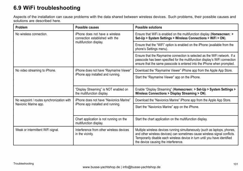
6.9 WiFi troubleshootingAspects of the installation can cause problems with the data shared between wireless devices. Such problems, their possible causes andsolutions are described here.
Problem Possible causes Possible solutions
Ensure that WiFi is enabled on the multifunction display (Homescreen: >Set-Up > System Settings > Wireless Connections > WiFi > ON).
Ensure that the “WiFi” option is enabled on the iPhone (available from thephone’s Settings menu).
No wireless connection. iPhone does not have a wirelessconnection established with themultifunction display.
Ensure that the Raymarine connection is selected as the WiFi network. If apasscode has been specified for the multifunction display’s WiFi connectionensure that the same passcode is entered into the iPhone when prompted.
Download the “Raymarine Viewer” iPhone app from the Apple App Store.iPhone does not have “Raymarine Viewer”iPhone app installed and running.
Start the “Raymarine Viewer” app on the iPhone.
No video streaming to iPhone.
“Display Streaming” is NOT enabled onthe multifunction display.
Enable “Display Streaming” (Homescreen: > Set-Up > System Settings >Wireless Connections > Display Streaming > ON).
Download the “Navionics Marine” iPhone app from the Apple App Store.iPhone does not have “Navionics Marine”iPhone app installed and running.
Start the “Navionics Marine” app on the iPhone.
No waypoint / routes synchronization withNavionic Marine app.
Chart application is not running on themultifunction display.
Start the chart application on the multifunction display.
Weak or intermittent WiFi signal. Interference from other wireless devicesin the vicinity.
Multiple wireless devices running simultaneously (such as laptops, phones,and other wireless devices) can sometimes cause wireless signal conflicts.Temporarily disable each wireless device in turn until you have identifiedthe device causing the interference.
Troubleshooting 101www.busse-yachtshop.de | [email protected]
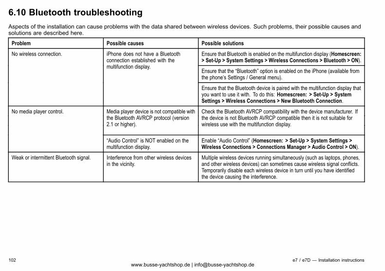
6.10 Bluetooth troubleshootingAspects of the installation can cause problems with the data shared between wireless devices. Such problems, their possible causes andsolutions are described here.
Problem Possible causes Possible solutions
Ensure that Bluetooth is enabled on the multifunction display (Homescreen:> Set-Up > System Settings > Wireless Connections > Bluetooth > ON).
Ensure that the “Bluetooth” option is enabled on the iPhone (available fromthe phone’s Settings / General menu).
No wireless connection. iPhone does not have a Bluetoothconnection established with themultifunction display.
Ensure that the Bluetooth device is paired with the multifunction display thatyou want to use it with. To do this: Homescreen: > Set-Up > SystemSettings > Wireless Connections > New Bluetooth Connection.
Media player device is not compatible withthe Bluetooth AVRCP protocol (version2.1 or higher).
Check the Bluetooth AVRCP compatibility with the device manufacturer. Ifthe device is not Bluetooth AVRCP compatible then it is not suitable forwireless use with the multifunction display.
No media player control.
“Audio Control” is NOT enabled on themultifunction display.
Enable “Audio Control” (Homescreen: > Set-Up > System Settings >Wireless Connections > Connections Manager > Audio Control > ON).
Weak or intermittent Bluetooth signal. Interference from other wireless devicesin the vicinity.
Multiple wireless devices running simultaneously (such as laptops, phones,and other wireless devices) can sometimes cause wireless signal conflicts.Temporarily disable each wireless device in turn until you have identifiedthe device causing the interference.
102 e7 / e7D — Installation instructionswww.busse-yachtshop.de | [email protected]
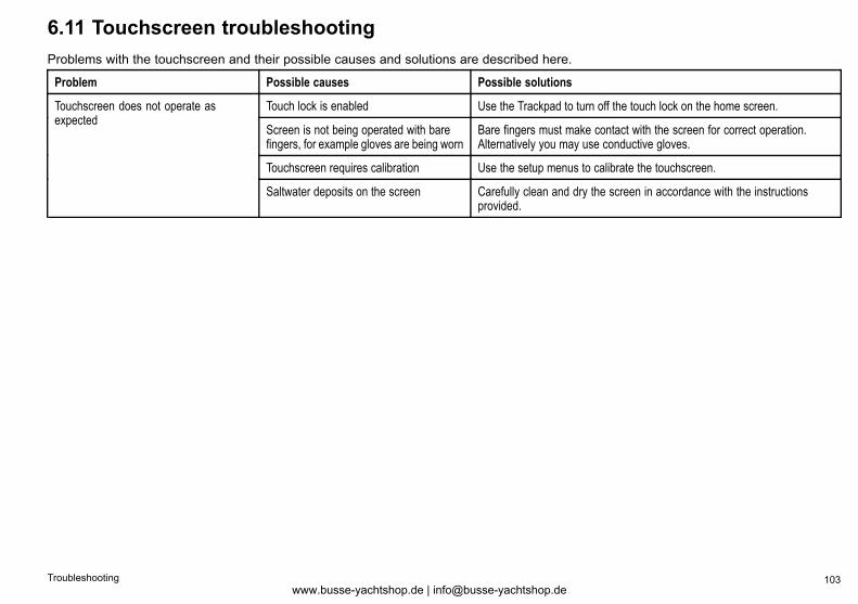
6.11 Touchscreen troubleshootingProblems with the touchscreen and their possible causes and solutions are described here.
Problem Possible causes Possible solutions
Touch lock is enabled Use the Trackpad to turn off the touch lock on the home screen.
Screen is not being operated with barefingers, for example gloves are being worn
Bare fingers must make contact with the screen for correct operation.Alternatively you may use conductive gloves.
Touchscreen requires calibration Use the setup menus to calibrate the touchscreen.
Touchscreen does not operate asexpected
Saltwater deposits on the screen Carefully clean and dry the screen in accordance with the instructionsprovided.
Troubleshooting 103www.busse-yachtshop.de | [email protected]
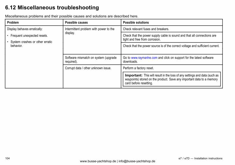
6.12 Miscellaneous troubleshootingMiscellaneous problems and their possible causes and solutions are described here.
Problem Possible causes Possible solutions
Check relevant fuses and breakers.
Check that the power supply cable is sound and that all connections aretight and free from corrosion.
Intermittent problem with power to thedisplay.
Check that the power source is of the correct voltage and sufficient current.
Software mismatch on system (upgraderequired).
Go to www.raymarine.com and click on support for the latest softwaredownloads.
Display behaves erratically:
• Frequent unexpected resets.
• System crashes or other erraticbehavior.
Corrupt data / other unknown issue. Perform a factory reset.
Important: This will result in the loss of any settings and data (such aswaypoints) stored on the product. Save any important data to a memorycard before resetting.
104 e7 / e7D — Installation instructionswww.busse-yachtshop.de | [email protected]

Chapter 7: Technical support
Chapter contents• 7.1 Raymarine customer support on page 106
• 7.2 Third-party support on page 107
Technical support 105www.busse-yachtshop.de | [email protected]
7.1 Raymarine customer supportRaymarine provides a comprehensive customer support service.You can contact customer support through the Raymarine website,telephone and email. If you are unable to resolve a problem, pleaseuse any of these facilities to obtain additional help.
Web supportPlease visit the customer support area of our website at:www.raymarine.comThis contains Frequently Asked Questions, servicing information,e-mail access to the Raymarine Technical Support Department anddetails of worldwide Raymarine agents.
Telephone and email supportIn the USA:• Tel: +1 603 881 5200 extension 2444• Email: [email protected]
In the UK, Europe, the Middle East, or Far East:• Tel: +44 (0)23 9271 4713• Email: [email protected]
Product informationIf you need to request service, please have the following informationto hand:
• Product name.
• Product identity.
• Serial number.
• Software application version.
You can obtain this product information using the menus within yourproduct.
Viewing product informationWith the homescreen displayed:1. Select Set-up.2. Select Maintenance.3. Select Diagnostics.4. Select Select Device.5. Select the relevant product from the list.6. Select Show All Data.
106 e7 / e7D — Installation instructionswww.busse-yachtshop.de | [email protected]
7.2 Third-party supportContact and support details for third-party suppliers can be found onthe appropriate websites.
Navionicswww.navionics.com
Siriuswww.sirius.com
Technical support 107www.busse-yachtshop.de | [email protected]

108 e7 / e7D — Installation instructionswww.busse-yachtshop.de | [email protected]
Chapter 8: Technical specification
Chapter contents• 8.1 Technical specification on page 110
Technical specification 109www.busse-yachtshop.de | [email protected]
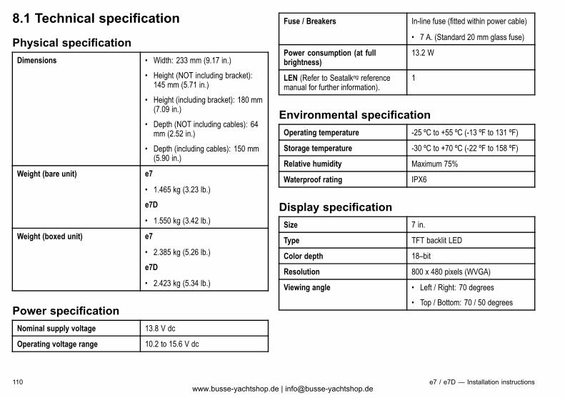
8.1 Technical specification
Physical specificationDimensions • Width: 233 mm (9.17 in.)
• Height (NOT including bracket):145 mm (5.71 in.)
• Height (including bracket): 180 mm(7.09 in.)
• Depth (NOT including cables): 64mm (2.52 in.)
• Depth (including cables): 150 mm(5.90 in.)
Weight (bare unit) e7
• 1.465 kg (3.23 lb.)
e7D
• 1.550 kg (3.42 lb.)
Weight (boxed unit) e7
• 2.385 kg (5.26 lb.)
e7D
• 2.423 kg (5.34 lb.)
Power specificationNominal supply voltage 13.8 V dc
Operating voltage range 10.2 to 15.6 V dc
Fuse / Breakers In-line fuse (fitted within power cable)
• 7 A. (Standard 20 mm glass fuse)
Power consumption (at fullbrightness)
13.2 W
LEN (Refer to Seatalkng referencemanual for further information).
1
Environmental specificationOperating temperature -25 ºC to +55 ºC (-13 ºF to 131 ºF)
Storage temperature -30 ºC to +70 ºC (-22 ºF to 158 ºF)
Relative humidity Maximum 75%
Waterproof rating IPX6
Display specificationSize 7 in.
Type TFT backlit LED
Color depth 18–bit
Resolution 800 x 480 pixels (WVGA)
Viewing angle • Left / Right: 70 degrees
• Top / Bottom: 70 / 50 degrees
110 e7 / e7D — Installation instructionswww.busse-yachtshop.de | [email protected]
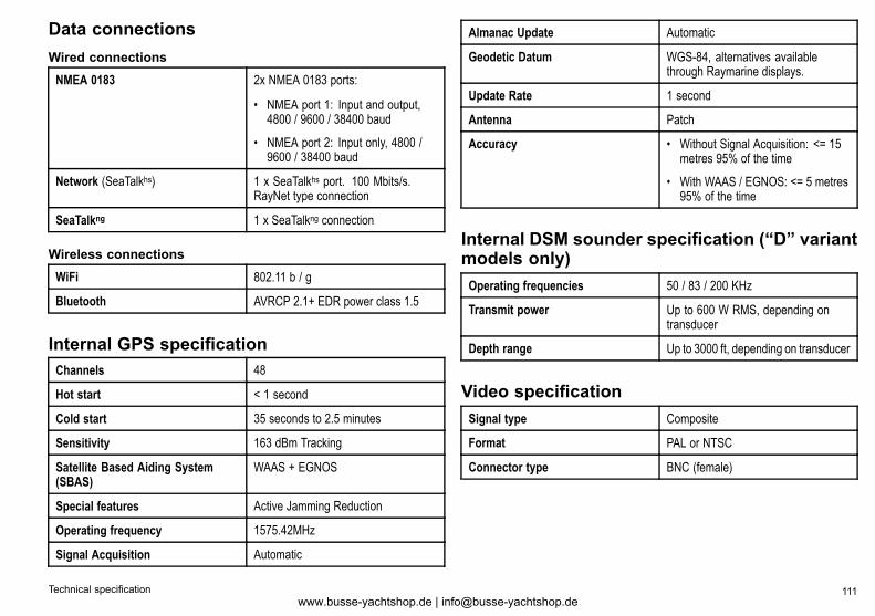
Data connectionsWired connections
NMEA 0183 2x NMEA 0183 ports:
• NMEA port 1: Input and output,4800 / 9600 / 38400 baud
• NMEA port 2: Input only, 4800 /9600 / 38400 baud
Network (SeaTalkhs) 1 x SeaTalkhs port. 100 Mbits/s.RayNet type connection
SeaTalkng 1 x SeaTalkng connection
Wireless connections
WiFi 802.11 b / g
Bluetooth AVRCP 2.1+ EDR power class 1.5
Internal GPS specificationChannels 48
Hot start < 1 second
Cold start 35 seconds to 2.5 minutes
Sensitivity 163 dBm Tracking
Satellite Based Aiding System(SBAS)
WAAS + EGNOS
Special features Active Jamming Reduction
Operating frequency 1575.42MHz
Signal Acquisition Automatic
Almanac Update Automatic
Geodetic Datum WGS-84, alternatives availablethrough Raymarine displays.
Update Rate 1 second
Antenna Patch
Accuracy • Without Signal Acquisition: <= 15metres 95% of the time
• With WAAS / EGNOS: <= 5 metres95% of the time
Internal DSM sounder specification (“D” variantmodels only)Operating frequencies 50 / 83 / 200 KHz
Transmit power Up to 600 W RMS, depending ontransducer
Depth range Up to 3000 ft, depending on transducer
Video specificationSignal type Composite
Format PAL or NTSC
Connector type BNC (female)
Technical specification 111www.busse-yachtshop.de | [email protected]
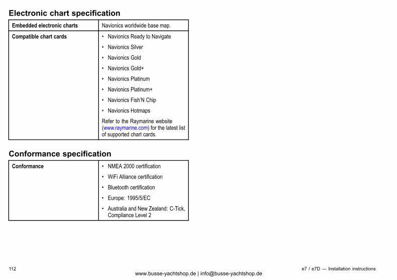
Electronic chart specificationEmbedded electronic charts Navionics worldwide base map.
Compatible chart cards • Navionics Ready to Navigate
• Navionics Silver
• Navionics Gold
• Navionics Gold+
• Navionics Platinum
• Navionics Platinum+
• Navionics Fish’N Chip
• Navionics Hotmaps
Refer to the Raymarine website(www.raymarine.com) for the latest listof supported chart cards.
Conformance specificationConformance • NMEA 2000 certification
• WiFi Alliance certification
• Bluetooth certification
• Europe: 1995/5/EC
• Australia and New Zealand: C-Tick,Compliance Level 2
112 e7 / e7D — Installation instructionswww.busse-yachtshop.de | [email protected]
Chapter 9: Options and accessories
Chapter contents• 9.1 Spares and accessories on page 114
Options and accessories 113www.busse-yachtshop.de | [email protected]
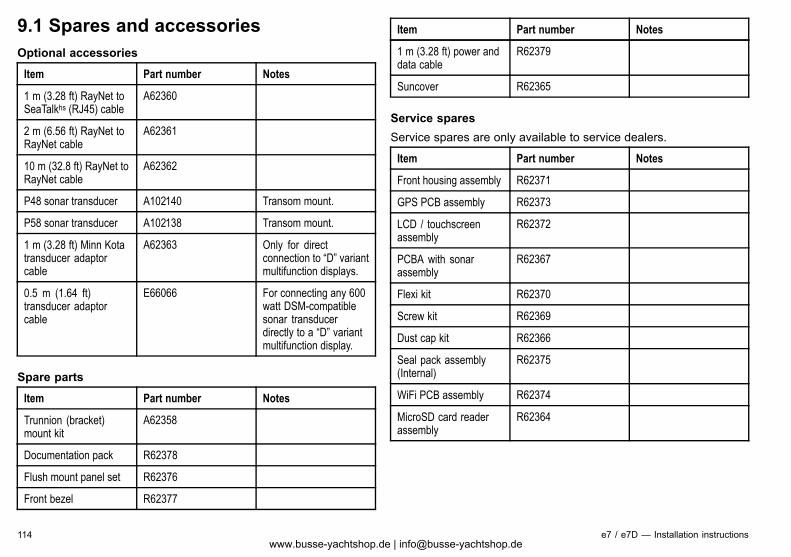
9.1 Spares and accessoriesOptional accessories
Item Part number Notes
1 m (3.28 ft) RayNet toSeaTalkhs (RJ45) cable
A62360
2 m (6.56 ft) RayNet toRayNet cable
A62361
10 m (32.8 ft) RayNet toRayNet cable
A62362
P48 sonar transducer A102140 Transom mount.
P58 sonar transducer A102138 Transom mount.
1 m (3.28 ft) Minn Kotatransducer adaptorcable
A62363 Only for directconnection to “D” variantmultifunction displays.
0.5 m (1.64 ft)transducer adaptorcable
E66066 For connecting any 600watt DSM-compatiblesonar transducerdirectly to a “D” variantmultifunction display.
Spare parts
Item Part number Notes
Trunnion (bracket)mount kit
A62358
Documentation pack R62378
Flush mount panel set R62376
Front bezel R62377
Item Part number Notes
1 m (3.28 ft) power anddata cable
R62379
Suncover R62365
Service sparesService spares are only available to service dealers.
Item Part number Notes
Front housing assembly R62371
GPS PCB assembly R62373
LCD / touchscreenassembly
R62372
PCBA with sonarassembly
R62367
Flexi kit R62370
Screw kit R62369
Dust cap kit R62366
Seal pack assembly(Internal)
R62375
WiFi PCB assembly R62374
MicroSD card readerassembly
R62364
114 e7 / e7D — Installation instructionswww.busse-yachtshop.de | [email protected]
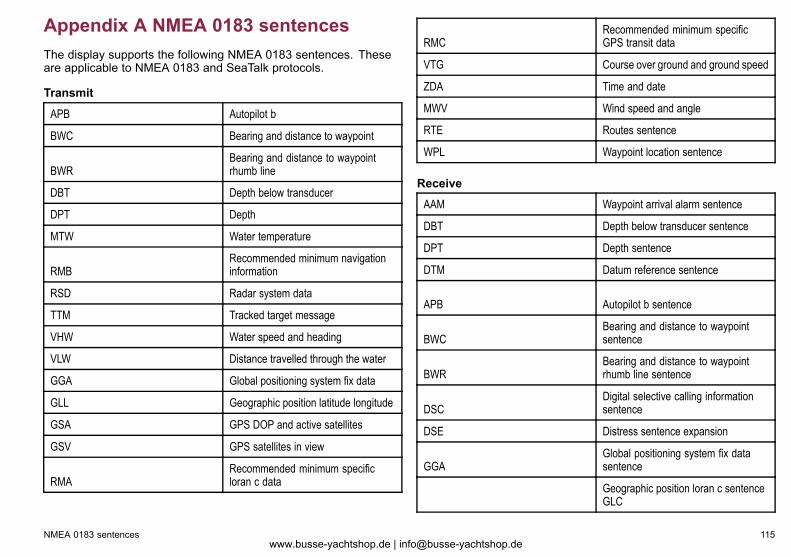
Appendix A NMEA 0183 sentencesThe display supports the following NMEA 0183 sentences. Theseare applicable to NMEA 0183 and SeaTalk protocols.
Transmit
APB Autopilot b
BWC Bearing and distance to waypoint
BWRBearing and distance to waypointrhumb line
DBT Depth below transducer
DPT Depth
MTW Water temperature
RMBRecommended minimum navigationinformation
RSD Radar system data
TTM Tracked target message
VHW Water speed and heading
VLW Distance travelled through the water
GGA Global positioning system fix data
GLL Geographic position latitude longitude
GSA GPS DOP and active satellites
GSV GPS satellites in view
RMARecommended minimum specificloran c data
RMCRecommended minimum specificGPS transit data
VTG Course over ground and ground speed
ZDA Time and date
MWV Wind speed and angle
RTE Routes sentence
WPL Waypoint location sentence
Receive
AAM Waypoint arrival alarm sentence
DBT Depth below transducer sentence
DPT Depth sentence
DTM Datum reference sentence
APB Autopilot b sentence
BWCBearing and distance to waypointsentence
BWRBearing and distance to waypointrhumb line sentence
DSCDigital selective calling informationsentence
DSE Distress sentence expansion
GGAGlobal positioning system fix datasentence
Geographic position loran c sentenceGLC
NMEA 0183 sentences 115www.busse-yachtshop.de | [email protected]
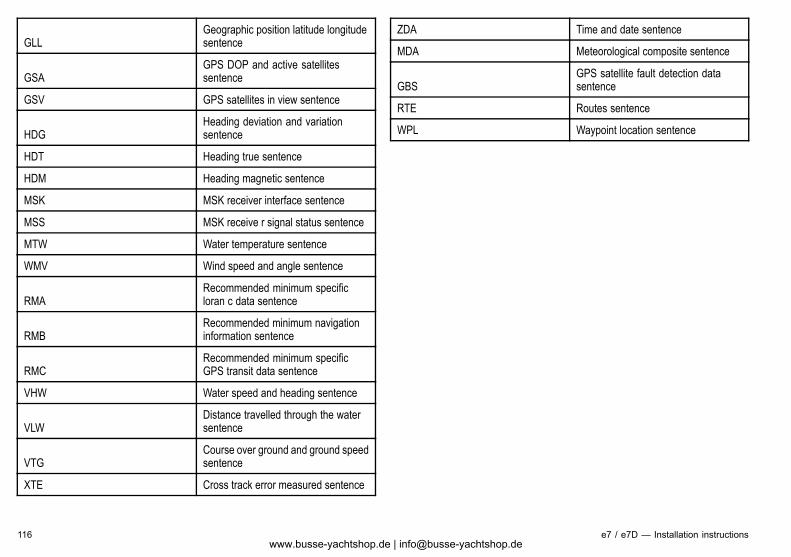
GLLGeographic position latitude longitudesentence
GSAGPS DOP and active satellitessentence
GSV GPS satellites in view sentence
HDGHeading deviation and variationsentence
HDT Heading true sentence
HDM Heading magnetic sentence
MSK MSK receiver interface sentence
MSS MSK receive r signal status sentence
MTW Water temperature sentence
WMV Wind speed and angle sentence
RMARecommended minimum specificloran c data sentence
RMBRecommended minimum navigationinformation sentence
RMCRecommended minimum specificGPS transit data sentence
VHW Water speed and heading sentence
VLWDistance travelled through the watersentence
VTGCourse over ground and ground speedsentence
XTE Cross track error measured sentence
ZDA Time and date sentence
MDA Meteorological composite sentence
GBSGPS satellite fault detection datasentence
RTE Routes sentence
WPL Waypoint location sentence
116 e7 / e7D — Installation instructionswww.busse-yachtshop.de | [email protected]
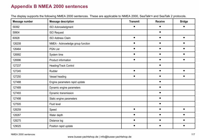
Appendix B NMEA 2000 sentences
The display supports the following NMEA 2000 sentences. These are applicable to NMEA 2000, SeaTalkng and SeaTalk 2 protocols.
Message number Message description Transmit Receive Bridge
59392 ISO Acknowledgment ● ● ●
59904 ISO Request ●
60928 ISO Address Claim ● ● ●
126208 NMEA - Acknowledge group function ● ● ●
126464 PGN List ● ● ●
126992 System time ● ● ●
126996 Product information ● ● ●
127237 Heading/Track Control ●
127245 Rudder ● ● ●
127250 Vessel heading ● ● ●
127488 Engine parameters rapid update ●
127489 Dynamic engine parameters ●
127493 Dynamic transmission ●
127498 Static engine parameters ●
127505 Fluid level ●
128259 Speed ● ● ●
128267 Water depth ● ● ●
128275 Distance log ● ● ●
129025 Position rapid update ● ● ●
NMEA 2000 sentences 117www.busse-yachtshop.de | [email protected]
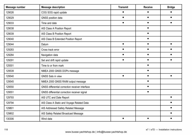
Message number Message description Transmit Receive Bridge
129026 COG SOG rapid update ● ● ●
129029 GNSS position data ● ● ●
129033 Time and date ● ● ●
129038 AIS Class A Position Report ●
129039 AIS Class B Position Report ●
129040 AIS Class B Extended Position Report ●
129044 Datum ● ● ●
129283 Cross track error ● ● ●
129284 Navigation data ● ● ●
129291 Set and drift rapid update ● ● ●
129301 Time to or from mark ●
129539 NMEA 2000 GNSS DOPs message ●
129540 GNSS Sats in view ● ● ●
129545 NMEA 2000 GNSS RAIM output message ●
129550 GNSS differential correction receiver interface ●
129551 GNSS differential correction receiver signal ●
129793 AIS UTC and Date Report ●
129794 AIS Class A Static and Voyage Related Data ●
129801 AIS Addressed Safety Related Message ●
129802 AIS Safety Related Broadcast Message ●
130306 Wind data ● ● ●
118 e7 / e7D — Installation instructionswww.busse-yachtshop.de | [email protected]
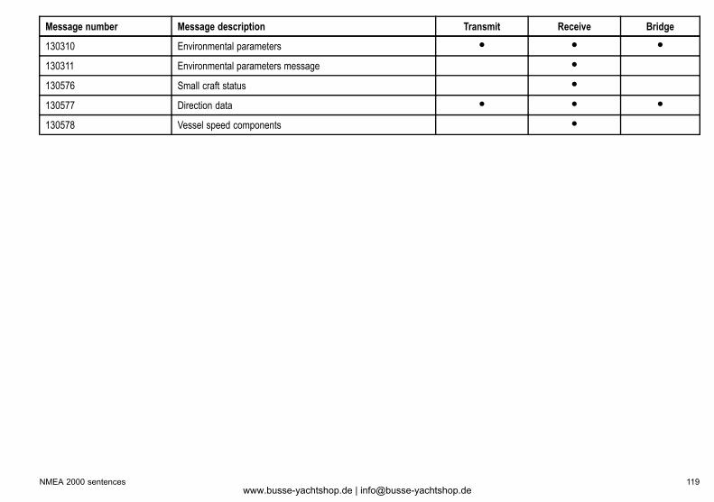
Message number Message description Transmit Receive Bridge
130310 Environmental parameters ● ● ●
130311 Environmental parameters message ●
130576 Small craft status ●
130577 Direction data ● ● ●
130578 Vessel speed components ●
NMEA 2000 sentences 119www.busse-yachtshop.de | [email protected]
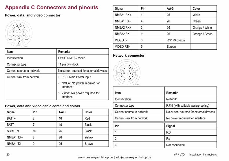
Appendix C Connectors and pinoutsPower, data, and video connector
D12186-1
1 84 9
2 7
3 65
11
10
Item Remarks
Identification PWR / NMEA / Video
Connector type 11 pin twist-lock
Current source to network No current sourced for external devices
Current sink from network • PSU: Main Power input.
• NMEA: No power required forinterface.
• Video: No power required forinterface.
Power, data and video cable cores and colors
Signal Pin AWG Color
BATT+ 2 16 Red
BATT- 7 16 Black
SCREEN 10 26 Black
NMEA1 TX+ 8 26 Yellow
NMEA1 TX- 9 26 Brown
Signal Pin AWG Color
NMEA1 RX+ 1 26 White
NMEA1 RX- 4 26 Green
NMEA2 RX+ 3 26 Orange / White
NMEA2 RX- 11 26 Orange / Green
VIDEO IN 6 RG179 coaxial
VIDEO RTN 5 Screen
Network connector
D12187-1
1
58
9 10
67
4
2 3
Item Remarks
Identification Network
Connector type RJ45 (with suitable waterproofing)
Current source to network No current sourced for external devices
Current sink from network No power required for interface
Pin Signal
1 Rx+
2 Rx-
3 Not connected
120 e7 / e7D — Installation instructionswww.busse-yachtshop.de | [email protected]
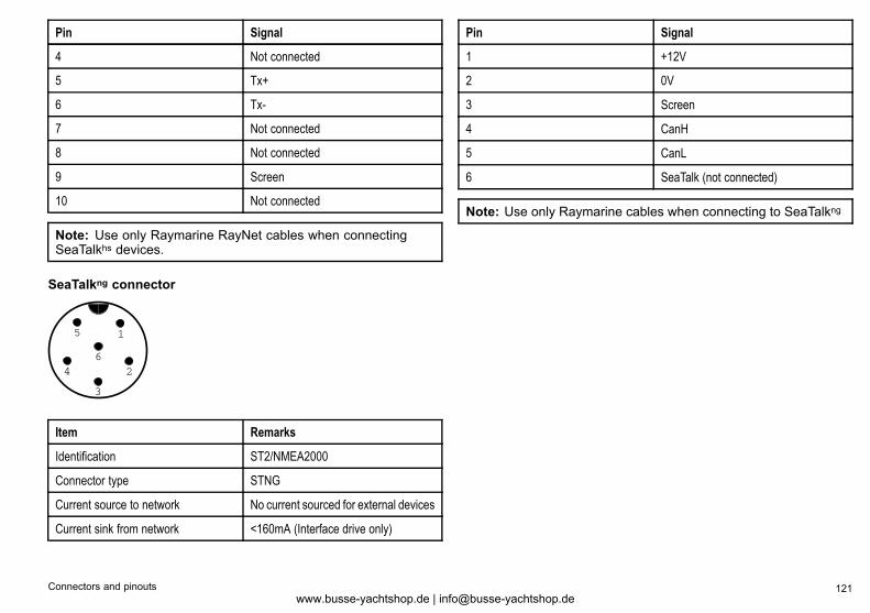
Pin Signal
4 Not connected
5 Tx+
6 Tx-
7 Not connected
8 Not connected
9 Screen
10 Not connected
Note: Use only Raymarine RayNet cables when connectingSeaTalkhs devices.
SeaTalkng connector
1
2
3
4
5
6
Item Remarks
Identification ST2/NMEA2000
Connector type STNG
Current source to network No current sourced for external devices
Current sink from network <160mA (Interface drive only)
Pin Signal
1 +12V
2 0V
3 Screen
4 CanH
5 CanL
6 SeaTalk (not connected)
Note: Use only Raymarine cables when connecting to SeaTalkng
Connectors and pinouts 121www.busse-yachtshop.de | [email protected]

122 e7 / e7D — Installation instructionswww.busse-yachtshop.de | [email protected]

www.busse-yachtshop.de | [email protected]