easy commissioning guide – fronius pv-system …
TRANSCRIPT
02/2017 1/24
EASY COMMISSIONING GUIDE – FRONIUS PV-SYSTEM CONTROLLER
Reading this document does not substitute for user’s reference to CIRCUTOR CDP-DUO user-guide.
1.1 Scope
Using Fronius grid-tie inverters in remote energy distribution systems that are powered by fossil-fuel powered Gensets require an appropriate/optimal control to maintain stable grid. This is achieved by maintaining a minimum load level at the Genset, in order to always have enough spinning reserve in the system, and to also attain good power quality. Typically, such a minimum load level is about 30% of the Gensets nominal power, to avoid an increase in excessive wear-and-tear of the Genset components. The associated control algorithm is implemented in the Fronius PV System Controller. The power analyzer measures the load to calculate the maximum power target values for PV-inverters in order to reduce the load on the Genset to a minimum acceptable level, but not below the desired/pre-defined minimum.
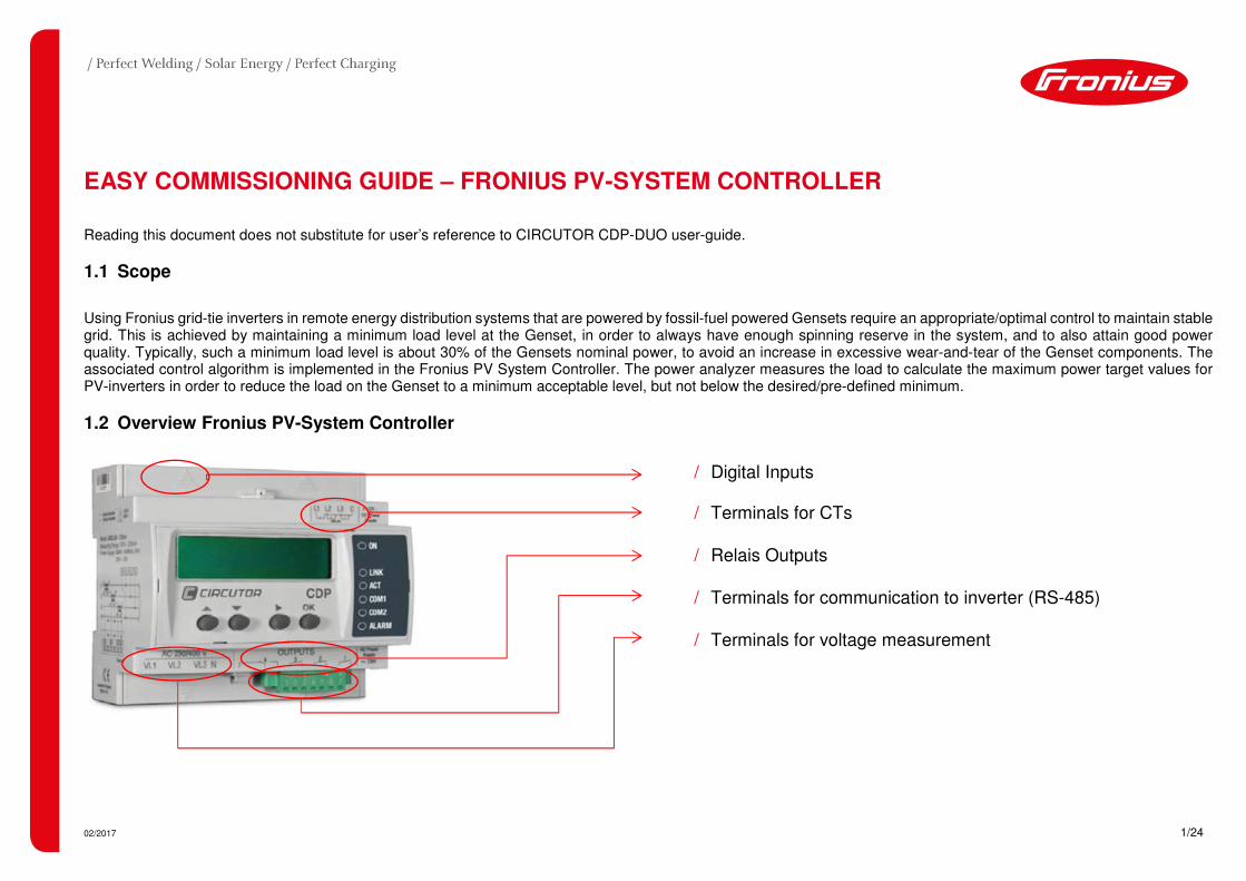
1.2 Overview Fronius PV-System Controller
/ Digital Inputs
/ Terminals for CTs
/ Relais Outputs
/ Terminals for communication to inverter (RS-485)
/ Terminals for voltage measurement

02/2017 2/24
1.2.1 Current Transducers (CTs)
The CTs for Fronius PV System Controllers are customised transducers with a secondary current of 250mA. This customisation is considered to achieve highest accuracy
for measurement purposes.
Standard 5A/1A CTs cannot be used in the standard setup.
CTs are available for the following maximum amperage:
/ MC-3 250A/3-phase (43,0010,0407)
/ MC-1/55 500A/1000A/1500A/1-phase (43,0010,0323)
/ MC-1/80 1000A/1500A/2000A/1-phase (43,0010,0322)
Do note that the amperage of the CT’s must be able to withstand the maximum amperage of the applied diesel generators.

02/2017 3/24
Use of standard CT’s
The use of Standard CT’s is possible by using a special external measurement extension that is not sourced via Fronius. In that case any standard 1A/5A CTs – even split core can be used. Do note that this setup might slightly increase response times for communication signal delay reasons.
/ Alternative measurement extension: CVM MINI-ITF-RS485-C2 (Code: M52021) / Current transducers: Any standard 1A/5A CTs will do

02/2017 4/24
1.2.2 Communication
The following communication channels are provided by the Fronius PV System Controller:
/ R1: Ethernet Modbus TCP (CDP is Server) – optional, see Circutor manual for register specification and details
/ R2 (pins 1-5): RS-422, RS-485, RS-232 Modbus RTU (CDP is Master) – mandatory, to exclusively connect to the Fronius Datamanager 2.0
/ R3 (pins 5-7): RS-485 only Only used for optional Circutor measurement extension (CVM Mini)
Terminals (Channel R2)
RS-485 (FRONIUS MODBUS)
1 D+
2
3 D-
4
5 GND
/ 2-wire MODBUS RTU (twisted pair) for connection to Fronius Datamanager 2.0.

02/2017 5/24
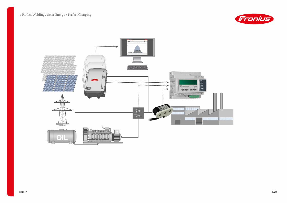
1.3 How can minimum Genset loading be achieved?
/ Place the Fronius PV System Controller along the path of consumption.
/ Link Fronius PV System Controller for MODBUS RTU communication to the Fronius Datamanager 2.0.
/ The feed-in limit can be changed and the range can vary from -999 to 100% of the inverter’s nominal power.
02/2017 6/24

02/2017 7/24
1.3.1 PV-Genset functional description
The control loop of Fronius PV System Controllers is based on the fast measurement of loads with a full scale power analyzer to realize a consumption based dynamic
curtailment of PV inverter power. The point of measurement has to be a pure path of consumption excluding the generation.
Furthermore the Fronius PV inverters can contribute to an improved power factor in the system by providing a part of the required reactive power.
The PV System Controller determines the setpoints within the range of a power factor (PF = ±0.8).
1.3.2 Compatibility with Fronius inverters
The Fronius PV System Controller can principally be used with all Fronius inverters that allow dynamic active power curtailment.
Nevertheless the desired product for three-phase inverters will be Fronius SYMO and ECO inverters.
/ Fronius Symo with Datamanager 2.0 and later
/ Fronius Eco with Datamanager 2.0 and later

02/2017 8/24
1.4 Easy commissioning Fronius PV System Controller and Fronius Datamanager 2.0
Terminals RS-485 (FRONIUS MODBUS)
1 D+
2
3 D-
4
5 GND
Fronius PV System Controller Fronius Datamanager 2.0
Terminals RS-485 Description
D+ Modbus Data + D- Modbus Data - - Signal GND always connect)
02/2017 9/24
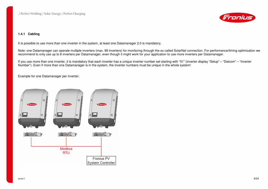
1.4.1 Cabling
It is possible to use more than one inverter in the system, at least one Datamanager 2.0 is mandatory. Note: one Datamanager can operate multiple inverters (max. 99 inverters) for monitoring through the so called SolarNet connection. For performance/timing optimization we recommend to only use up to 6 inverters per Datamanager, even though it might work for your application to use more inverters per Datamanager. If you use more than one inverter, it is mandatory that each inverter has a unique inverter number set starting with “01” (inverter display “Setup” – “Datcom” – “Inverter Number”). Even if more than one Datamanager is in the system, the inverter numbers must be unique in the whole system! Example for one Datamanager per inverter:

02/2017 10/24
Example for multiple inverters per Datamanager via SolarNet (a part system – full color image right); more than one part-system is possible (greyed out left part):

02/2017 11/24
1.4.2 Modbus RTU cabling
The Modbus RTU cabling must be carried out according to RS-485 specifications.
/ Shielded twisted pair cabling, especially D+/D- must be one twisted pair
/ Connect the signal GND between all bus subscribers (CDP and all Datamanagers)
/ Use shielded twisted pair cables and connect the shield only to PE (earth potential, do not mix up with signal-GND!)
/ Electromagnetic compatibility (shielding) must meet local standards; if nothing is inherent we recommend to use one PE-connection to avoid compensating currents
due to possible earth loops
/ Connect the wires in a bus topology, point-to-point (no star topology allowed)
/ Place a 120 Ohm termination resistor at each end of the RS485-busline (last Datamanager: mini DIP switch ON; CDP: separate resistor)
RS-485 wiring example for 2 Datamanagers and one CDP
Note: the Master/Slave switch on each Datamanager must be set to “Master”

02/2017 12/24
1.4.3 Wiring diagram (3-phase)
12 VDC
AUX

02/2017 13/24
1.4.4 Settings for Fronius Datamanager 2.0
Open the Fronius Datamanager 2.0 web interface in your browser and navigate to “Settings” (when prompted for the password, please enter the “service” password). Then select the “Modbus” tab and enter the options as depicted in the picture below. Save the settings by ticking the .
Figure 1: Fronius Datamanager Web UI – Modbus Settings

02/2017 14/24
Switch to the Fronius Datamanager 2.0 tab “DNO-Editor“, the priority of Modbus communication should per default be set to one. This is necessary to ensure that other possible inputs cannot overrule the PV System Controller to ensure appropriate communication, unless the Modbus cable breaks.
Figure 2: Fronius Datamanager Web UI – DNO Editor Settings

02/2017 15/24
1.4.5 Settings for the Fronius PV System Controller
Settings for the Fronius PV System Controller can be carried out either via the display or via the in-built Webserver. First, the unit has to be powered (230VAC at terminals 17 and 18 or 12V at terminals 19 and 20) followed by the voltage (terminals 1, 3, 5 und 6) and current transducers (CTs) at the terminals 21 to 24 as depicted in the schematic under 1.4.3.
The PV System Controller is connected via Ethernet-Port to the Local Network (LAN). Is a DHCP-Server available, the Fronius PV System Controller gets the IP address automatically. Refer to the user-manual for manual configuration of network settings. The web interface for the configuration of Fronius PV System Controllers can only be performed via Google Chrome web browser. Visit the following URL: https://xxx.xxx.xxx.xxx/setup/index.html (xxx.xxx.xxx.xxx stands for the IP address of PV System Controllers which can be accessed via the display as follows: push the buttons in the following order: � ���).
Menu Navigation for/to the IP-Address Figure 3: Connection/Configuration of (pin connections) PV System Controller

02/2017 16/24
/ Inverter type (1): Select “Fronius MB” for Modbus RTU
/ Inverter power (2): total inverter power of all connected units
/ Number of inverters (3): total number of connected inverters
/ Control mode (4): “Three phases” and “Active power III”
/ Injection margin (5) MAIN: Safety margin to limit (0 ... 100%)
/ Default value = 3% of desired setpoint
/ Allowed injection (5) MAIN: Minimum Genset loading: -999 ... 0%
/ To be set in percentile of total inverter power
/ Injection margin (5) SEC: Safety margin to limit (0 ... 100%)
/ Allowed injection (5) SEC: -999 ... +100% for on-grid operation
/ Enable Power Factor (6): Enables PF compensation mode
/ Force secondary mode (7): Main setting will be ignored
/ CT nominal current (8): Enter nominal current of the CTs in the load
analyzer section
�
�
� �
�
�
Figure 4: Web UI PV-System Controller

02/2017 17/24
Following below are the parameters with respect to the settings at/for Fronius PV System Controller:
/ Select “Fronius MB” in the drop-down field Inverter type.
/ The Inverter Power is the total active power of all Fronius inverters controlled by the Fronius PV System Controller.
Enter the number of all inverters controlled by Fronius PV System Controller in the field “Number of Inverters”.
/ Depending whether the system is 1- or 3-phase, in the Controls section the corresponding phase has to be selected.
Using 3-phase systems, in ”Three phase mode“ select active power III. This selection means that the power of phase 1,2 and 3 are summed up and this power is been
taken as a reference.
/ The value Allowed injection should be negative per default and is calculated according to the 30% minimum Genset loading in comparison to the inverter’s power (e.g.
100kW Genset, 30kWp PV-system, the value should be -100%).
−������� � �� �
�����������
= ������� ����� ���
The Injection margin which is basically a safety factor can be set to 3% per default. As an example, a measured consumption of 60 kW is now interpreted as 58.2 kW
and according to the example above, 30kW (minimum Genset loading) + 1.8 kW (injection margin) are drawn from the Genset (or grid) as an additional safety margin to
avoid backfeed.
The setpoint for the PV inverter is always a combination of both, Allowed injection (lead) and Injection margin (safety gap). If Injection margin is set to 0%, only the
Allowed injection applies.
/ Lastly, enter the nominal current of CTs (250A / 500A / 1000A / 1500A / 2000A).

02/2017 18/24
1.4.6 Examples
Note: if your automatic transfer switch (or contactor) uses a normally open (NO) contact between pin 36 and 28 (Input 1), the PV System Controller is only in MAIN mode when the contactor is not energized, that is typically when no grid is present. Be aware, the value for “ALLOWED INJECTION” is in % of the total PV-power and has a negative sign to represent the function of “minimum Genset loading”. Example values for MAIN = Genset operation and SECONDARY = Zero-Feed-In when the system is in grid parallel operation (NO contact): MAIN SECONDARY
INJECTION MARGIN 3% 3% ALLOWED INJECTION -100% 0%
Example values for MAIN = Genset operation and SECONDARY = Full-Feed-In when the system is in grid parallel operation (NO contact): MAIN SECONDARY
INJECTION MARGIN 3% 3% ALLOWED INJECTION -100% 100%

02/2017 19/24
1.5 Fail-Safe mechanism
In case the Modbus connection between the Fronius PV System Controller and the Datamanager is broken, the inverter will fall back to a predefined value. This value can be set either in the “Dynamic power reduction” section of the Datamanager user interface (recommended) or in the “IO control” section, depending on your selected priority. Both sections are found in the “DNO editor” settings. If the connection breaks the Datamanager enters the next configured control mode 10 seconds after the last valid Modbus message from the PV System Controller. We recommend to set the controlling priority as follows:
The fallback values are up to your system requirements, to be safe in terms of minimum Genset loading a limit of 1% can be recommended and set under “Dynamic power reduction” or “IO control” section. If the Modbus connection fails, the inverters are operating with 1% (max. 300 W) in this example.

02/2017 20/24
If you prefer the IO controls a second controlling priority:
In case the communication between inverters in a Fronius Datcom ring topology is interrupted for any reason, the inverters that do not receive a proper communication signal will enter a safe state and will not contribute to the system any longer. This setting has to be activated in the Fronius “professional” menu. To get the access code for that menu please contact Fronius Tech Support. If you receive the access code, tap the second button from right (below the inverter display) five times until “00000” blinks and enter the access code. Confirm with enter. If the professional menu is entered, the display shows the following information:

02/2017 21/24
Scroll up until you select the entry „Fail-Safe”, confirm with enter
Select „DM FailSafe Mode“ and enter this menu
With +/- select „Permanent“ and confirm with enter (default = “OFF”)
Enter the „DM FailSafe Behaviour“ menu
Check that „Disconn.“ is selected
The system is now configured. Please load a country setup (access code 73887) according to your requirements, MG50 (Microgrid 50Hz) or MG60 (Microgrid, 60Hz) is recommended for Genset operation but that must be verified by your grid operator in case the system also operates in grid-parallel mode.

02/2017 22/24
APPENDIX – HOW TO USE THE GENSET MEASUREMENT EXTENSION The Fronius PV-Genset measurement extension is an optional component of the solution which is an additional measure to prevent feeding power back to the Genset. The purpose of the Genset measurement extension is that in case of reverse power to the Genset the PV System Controller triggers a circuit breaker that immediately disconnects the PV system via a circuit breaker. The risk of reverse power to the Genset increases in case of load rejection of large consumers or also in case of a big PV SYSTEM to Genset ratio, assuming that the standard fail-safe mechanism is not responding.
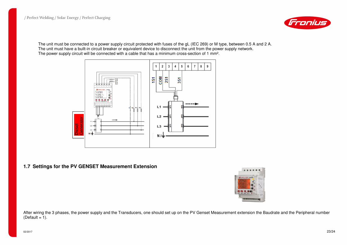
1.6 Wiring diagram Genset measurement extension
All information is collected by the PV System Controller to manage the behavior of the Fronius Inverter using the Modbus communication. The communication between PV System controller and measurement extension is established by using an RS485 cable between the PV System Controller and the Genset measurement extension. The communication between the The Genset measurement extension should be wired on the channel R3 of the PV GENSET Controller (see wiring diagram below).
/ The inputs 14/15 of the Genset measurement extension are used as a power supply (230 VAC). / Inputs for voltage sensing are: terminals 10/11/12 for the 3 phases and 13 for the neutral
/ Input terminals 1/2/3/5 are used for the MC3 (current clamps) connection.
02/2017 23/24
The unit must be connected to a power supply circuit protected with fuses of the gL (IEC 269) or M type, between 0.5 A and 2 A. The unit must have a built-in circuit breaker or equivalent device to disconnect the unit from the power supply network. The power supply circuit will be connected with a cable that has a minimum cross-section of 1 mm².
1.7 Settings for the PV GENSET Measurement Extension
After wiring the 3 phases, the power supply and the Transducers, one should set up on the PV Genset Measurement extension the Baudrate and the Peripheral number (Default = 1).
Die
se
l G
enera
tor

02/2017 24/24
1.7.1 Peripheral number
To access the COMMUNICATION Set-up, first press the Reset key and immediately press the Set-up key for a long time to enter a setting. Choose on the LEC display: SET NPER 001
The peripheral number varies between 0 and 255. To write or change the number of the peripheral, repeatedly press the key increasing the value of the digit which is flashing at the time.
When the required value is on the screen, move on to the following digit by pressing to allow the remaining values to be changed.
When the last digit has been changed, press to move back to the first digit, allowing the previously set values to be changed again. To enter the data and access
the next setting step, press .
1.7.2 Bauderate (Transmission speed)
The transmission speed of RS485 communication bus may be: 1,200 bps, 2,400 bps, 4,800 bps, 9,600 bps or 19,200 bps. For this case, you should use 19200 bps.
To select one of the transmission speeds available, press the max key and the four options will alternate in turn. Once the required option is selected, press the key to enter the data and access the next setting step.
The default
number is “001”